3300 high temperature proximity system · the 3300 high temperature proximity system can be used...
TRANSCRIPT

Specifications and Ordering Information Part Number 141623-01
Rev. C (08/07)
Page 1 of 17
Bently Nevada™ Asset Condition Monitoring
3300 High Temperature Proximity System
Description
Gas and steam turbines can produce temperatures hot enough to damage or destroy conventional proximity probes. The 3300 High Temperature Proximity System (HTPS) is designed to withstand the extreme temperatures found inside gas turbines, steam turbines and other types of rotating machinery. The HTPS measures vibration, thrust position, differential expansion and other parameters inside the hot areas of these machines. High temperature installations include:
• Near a labyrinth seal in steam turbines
• Differential expansion in steam turbines
• When probe cables are routed through struts that support the bearing housing of a gas turbine
• When probe cables are routed out through the exhaust path of a gas turbine
• Monitoring a troublesome bearing in a high temperature area
• Mode shape analysis at the mid-span location on steam and gas turbines for online machinery diagnostics
• Interstage radial and axial seal clearance measurements at the mid-span location of multi-stage steam turbines to minimize seal rubs
• Most hot bearing locations that can destroy conventional proximity probes
High temperature transducer with a rugged design
The 3300 High Temperature Proximity System can be used for proximity measurements at hot locations with excellent results. Customer benefits include:
• Proximity probe with integral hardline cable rated for +350°C (+662°F) continuous service in extreme conditions
• 4 mm (160 mils) of linear range for most measurements in the hot sections of the machine
• Hermetically-sealed ceramic probe tip seals out moisture and contaminants for added durability
• Ceramic tip and stainless steel construction resists heat, moisture and corrosion
• Threaded and smooth case styles for various types of probe mounting
• Hardline cable available in lengths of 1, 2 and 5 metres for routing cable through hot sections of the machine
• 3.94 V/mm (100 mV/mil) signal output compatible with virtually all new and existing Bently Nevada monitors and diagnostic equipment
Specifications and Ordering Information Part Number 141623-01
Rev. C (08/07)
Page 2 of 17
Mode shape analysis
The 3300 High Temperature Proximity System is used to protect and manage critical machines in your facility for increased safety and efficiency. It is also used for mode shape analysis when measurements are taken at the turbine mid-span location. Mode shape analysis is important for research and development of a new steam or gas turbine design or when troubleshooting an existing design. Mode identification probes provide lateral mode shape information which is extremely valuable for balancing rotating machinery and identifying faults such as shaft cracks, bearing failures, rotor-to-stator rubs and other machine problems.
For test and measurement applications, the HTPS will meet or exceed most requirements for making proximity measurements in high temperature environments. It is a viable option for your most challenging test problems.
The Bently Nevada 3300 High Temperature Proximity System is an advanced transducer designed for making proximity measurements at hot bearing locations in your machine. This transducer delivers dependable service in severe environments and is an ideal solution when using proximity probes at elevated temperatures.
Because of its thick hardline cable, the HTPS probe can be difficult to gap using a traditional threaded probe and bracket. Therefore, we recommend using smooth case probes, particularly if ordering a longer (2-metre or 5-metre) probe. The smooth case probes come with a clamp style mounting bracket to allow the probe to be gapped without turning.

Specifications and Ordering Information Part Number 141623-01
Rev. C (08/07)
Page 3 of 17
Specifications
Unless otherwise noted, the following specifications are for a a 3300 16 mm HTPS Proximitor® Sensor, matched extension cable and probe at 22 +4.4°C (72 +8°F), with a -24 Vdc power supply, a 10 kΩ load, a Bently Nevada supplied AISI 4140 steel target that is 31 mm (1.2 in) diameter or larger, and a probe gap of 2.5 mm (100 mils). The system accuracy and interchangeability specifications do not apply when using a transducer system calibrated to any target other than a Bently Nevada AISI 4140 steel target.
Electrical
Proximitor
Sensor Input
Accepts one noncontacting 3300 HTPS 16 mm Proximity Probe with matched Extension Cable.
Power
Requires -19.6 Vdc to -26 Vdc at 12 mA maximum consumption. Operation at a more positive volt-age than -23.5 Vdc can result in reduced linear range.
Supply
Sensitivity
Less than 13 mV change in output voltage per volt change in input voltage.
Output
resistance
50 Ω
Probe dc
resistance:
Probe Length (m) Resistance from the Center Conductor to the Outer
Conductor (RpROBE) (°hms)
1.0 5.06
2.0 5.82
5.0 8.11
Extension cable
dc resistance:
Length of Extension Cable
(m)
Resistance from CenterConductor
to Center Conductor
(RCORE) (ohms)
Resistance from Coaxial
Conductor to Coaxial
Conductor (RJACKET) (ohms)
4.0 0.88 0.26
7.0 1.62 0.49
8.0 1.84 0.55
Extension cable
capacitance:
69.9 pF/m (21.3 pF/ft) typical
Field wiring:
Maximum length of 305 metres (1,000 feet) between the 3300 HTPS Proximitor Sensor and the monitor. See the frequency response graph for signal rolloff at high frequencies when using longer field wiring lengths.
Linear Range:
4.0 mm (160 mils). Linear range begins at approximately 0.5 mm (20 mils) from target and is from 0.5 to 4.5 mm (20 to 180 mils) (approximately -2 to -18 Vdc).
Recommended
Gap Setting:
2.5 mm (100 mils)
Incremental
Scale Factor
(ISF)
3.94 V/mm (100 mV/mil) ±9.65% including interchangeability error when measured in increments of 0.5 mm (20 mils) over the 4.0 mm (160 mil) linear range.
Deviation from
best fit straight
line (DSL)
Less than ±78 |xm (±3.1 mils).

Specifications and Ordering Information Part Number 141623-01
Rev. C (08/07)
Page 4 of 17
System
performance
over extended
temperatures:
Over a probe temperature range of 22oCto+350°C (72oFto+662oF) the ISF remains within ±30% of 3.94 V/mm (100 mV/mil), the DSL remains within ±0.51 mm (±20 mils).
Frequency
Response:
0 to 6 kHz: +0, -3 dB typical, with up to 305 metres (1000 feet) of field wiring.
Recommended
Minimum
Target Size:
30.5 mm (1.2 in) diameter (flat target)
Recommended
Minimum Shaft
Diameter
152 mm (6.0 in)
Note: Measurements on shaft diameters smaller than 76 mm (3.0 in) usually require close spacing of radial vibration or axial position transducers with the potential for their electromagnetic emitted fields to interact with one another (cross talk), resulting in erroneous readings. Care should be taken to maintain minimum separation of transducer tips, generally at least 64 mm (2.5 in) for dual axial position measurements or 54 mm (2.1 in) for radial vibration measurements to prevent cross talk. Radial vibration or position measurements on shaft diameters smaller than 152 mm (6.0 in) will generally result in a change in scale factor due to the curvature of the shaft surface. Consult Performance Specification 159132 for additional information.
Effects of 60 Hz
Magnetic Fields
Up to 300
Gauss:
Output voltage in mil pp/gauss:
Gap Proximitor Sensor
Probe Ext. Cable
0.5 mm (20
mil)
0.0020 0.0030 0.0011
2.5 mm
(100 mil)
0.0042 0.0034 0.0046
4.5 mm
(180 mil)
0.0096 0.0070 0.0157
Electrical
Classification:
Complies with the European CE mark.
Hazardous Area Approvals
Not available.
Mechanical
Probe Tip Material:
Ceramic
Probe Case Material:
AISI 316L stainless steel (SST).
Probe Cable:
1, 2 or 5 metre length of AISI 304L SST hardline cable.
Extension Cable Material:
75 Q triaxial, fluoroethylene propylene (FEP) insulated.
Proximitor Sensor Material:
Aluminum with epoxy powder coat finish.
System Length:
9 metres including extension cable

Specifications and Ordering Information Part Number 141623-01
Rev. C (08/07)
Page 5 of 17
Extension Cable Armor (optional):
Flexible AISI 302 SST with FEP outer jacket.
Tensile Strength (maximum rated):
289 N (65 pounds) probe to extension cable.
Connector material:
Stainless steel
Probe case torque (maximum rated):
81 N.m (720 in.lb)
Connector-to-connector torque
Recommended
torque:
Finger tight + 1/8 turn
Maximum
torque:
0.565 N.m (5 in.lb)
Minimum Bend Radius (with or without sst armor):
25.4 mm (1.0 in)
System Weight (typicaI):
Probe:
117 g/m (1.26 oz/ft) of hardline cable + 12 g/cm (1.07 oz/in) of case
Extension
Cable:
45 g/m (0.5 oz/ft)
Armored
Extension
cable:
140 g/m (1.5 oz/ft)
Proximitor
Sensor:
255 g (9 oz)
Environmental Limit:
Probe
Temperature
Range
Operating and Storage Temperature:
-34oC to+350oC (-30°F to +662°F)
Extension Cable
Temperature
Range
Operating and Storage Temperature:
-5oC to +177°C (-60°F to +351 °F)
Proximitor
Sensor
Temperature
Range
Operating Temperature:
-5oC to +100°C (-60°F to +212°F)
Storage Temperature:
-5oC to +105°C (-60°F to +221 °F)
Probe Relative
Humidity:
100% condensing, submersible when connectors are protected.
Extension Cable
and Proximitor
Sensor Relative
Humidity:
100% condensing, non-submerged when connectors are protected.

Specifications and Ordering Information Part Number 141623-01
Rev. C (08/07)
Page 6 of 17
Probe Pressure:
3300 high temperature probes are designed to seal differential pressure between the probe tip and case. Probes are not pressure tested prior to shipment. Contact our custom design department if you require a test of the pressure seal for your application
Note: It is the responsibility of the customer or user to ensure that all liquids and gases are con-tained and safely controlled should leakage occur from a proximity probe. In addition, solutions with high or low pH values may erode the tip assembly of the probe causing media leakage into surrounding areas. Bently Nevada Corporation will not be held responsible for any damages resulting from leaking 3300 high temperature proximity probes. In addition, 3300 high temperature proximity probes will not be replaced under the service plan due to probe leakage.
Patents:
5,126,664
Components or procedures described in this patent apply to this product.
Ordering Information
3300 High Temperature Probe, 3/4-16 UNF threads:
330301-AXXX-BXXX-CXX-DXX-EXX-FXX
A: Unthreaded Length Option: Note: Unthreaded length must be at least 1.1 inch less than the case length.
Order in increments of 0.1 in Length configurations: Maximum unthreaded length: 5.4 in Minimum unthreaded length: 0.0 in Example: 0 1 2 = 1.2 in
B: Overall Case Length Option: Order in increments of 0.1 in Threaded length configurations: Maximum case length: 6.5 in Minimum case length: 1.1 in Example: 0 6 0 = 6.0 in
C: Hardline Length Option: 1 0 1.0 metre (3.3 feet) 2 0 2.0 metres (6.6 feet) 5 0 5.0 metres (16.4 feet)
D: Total Length Option: Note: Extension cable is included with the proximity probe.
9 0 9.0 metres (30 feet) E: Extension Cable Armor Option:
0 0 Without stainless steel armor 0 1 With stainless steel armor
F: Agency Approval Option: 0 0 Not required
3300 High Temperature Probe, M18 x 1.5 threads:
330302-AXXX-BXXX-CXX-DXX-EXX-FXX
A: Unthreaded Length Option: Note: Unthreaded length must be at least 30 mm less than the case length. Order in increments of 10 mm Length configurations: Maximum unthreaded length: 130mm Minimum unthreaded length: 0.0 mm Example: 0 5 0 = 50 mm
B: Overall Case Length Option: Order in increments of 10 mm Threaded length configurations: Maximum case length: 160 mm Minimum case length: 30 mm Example: 1 30 = 130 mm
C: Hardline Length Option: 1 0 1.0 metre (3.3 feet) 2 0 2.0 metres (6.6 feet) 5 0 5.0 metres (16.4 feet)
D: Total Length Option: Note: Extension cable is included with the proximity probe.
9 0 9.0 metres (30 feet)

Specifications and Ordering Information Part Number 141623-01
Rev. C (08/07)
Page 7 of 17
E: Extension Cable Armor Option: 0 0 Without stainless steel armor 0 1 With stainless steel armor
F: Agency Approval Option: 0 0 Not required
3300 High Temperature Probe, Smooth Case:
330303-AXXX- BXX-CXX-DXX-EXX
A: Overall Case Length Option: Note: Mounting bracket is included with the proximity probe. Order in increments of 0.1 in (2.54 mm) Threaded length configurations: Maximum case length: 9.9 in (251.5 mm) Minimum case length: 0.6 in (15.2 mm) Example: 0 6 0 = 6.0 in (152.4 mm)
B: Hardline Length Option: 1 0 1.0 metre (3.3 feet) 2 0 2.0 metres (6.6 feet) 5 0 5.0 metres (16.4 feet)
C: Total Length Option: Note: Extension cable is included with the proximity probe.
9 0 9.0 metres (30 feet) D: Extension Cable Armor Option:
0 0 Without stainless steel armor 0 1 With stainless steel armor
E: Agency Approval Option: 0 0 Not required
3300 High Temperature Proximitor Sensor
330300-AXX-BXX
A: Total Length Option: Note: Extension cable is included with the proximity probe.
9 0 9.0 metres (29.5 feet) B: Agency Approval Option:
0 0 Not required
Accessories
134867-01
Manual
159132
Performance Specification 134835-01
Mounting bracket for 330303 smooth case probe (spare).
Spare Extension Cable
330330-AXXX-BXX-CXX
A: Cable Length Option: Note: Extension cable is already included with the proximity probe. This is a matched spare cable only.
0 40 4.0 metres (13.1 feet) 0 7 0 7.0 metres (23.0 feet) 0 8 0 8.0 metres (26.3 feet)
B: Armor Option: 0 0 Without stainless steel armor 0 1 With stainless steel armor
C: Agency Approval Option: 0 0 Not required
Table 1. Armor Length
Cable Length Option Armor Length ±0.05 m (0.17 ft)
040 1.9 metres (6.25 ft)
070 5.6 metres (18.4 ft)
080 6.6 metres (21.7 ft)
Field Wiring Cable
132501-AXX
1.0 mm2 (18 AWG), 3 conductor twisted, shielded cable for connections between Proximitor sensor and monitor. Terminal ring lugs are installed at each end, including an extra shield ring lug at the monitor end.
A: Cable Length Option in Feet: Order in increments of 1.0 foot (0.3 metres). Minimum length: 2 feet (0.6 metres) Maximum length: 99 feet (30 metres) Example: 15 = 15 feet (4.6 metres)

Specifications and Ordering Information Part Number 141623-01
Rev. C (08/07)
Page 8 of 17
Graphs and Dimensional Drawings
Figure 1. Typical 3300 HTPS Performance with System at High Temperature

Specifications and Ordering Information Part Number 141623-01
Rev. C (08/07)
Page 9 of 17
Figure 2. Typical 3300 HTPS Performance with System at Low Temperature

Specifications and Ordering Information Part Number 141623-01
Rev. C (08/07)
Page 10 of 17
Figure 3. Typical 3300 HTPS Performance with Probe at High Temperature

Specifications and Ordering Information Part Number 141623-01
Rev. C (08/07)
Page 11 of 17
Figure 4. Typical 3300 HTPS Performance with Proximitor Sensor at High Temperature
Specifications and Ordering Information Part Number 141623-01
Rev. C (08/07)
Page 12 of 17
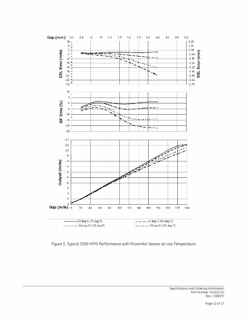
Figure 5. Typical 3300 HTPS Performance with Proximitor Sensor at Low Temperature

Specifications and Ordering Information Part Number 141623-01
Rev. C (08/07)
Page 13 of 17
Figure 6. Typical 3300 HTPS Amplitude Frequency Response with Cable Attached
Figure 7. Typical 3300 HTPS Phase Frequency Response with Cable Attached

Specifications and Ordering Information Part Number 141623-01
Rev. C (08/07)
Page 14 of 17
Figure 8. 330301 and 330302 HTPS Probe, English and Metric Threaded Versions
Figure 9. 330303 HTPS Smooth Case Probe

Specifications and Ordering Information Part Number 141623-01
Rev. C (08/07)
Page 15 of 17
Figure 10. Mounting Clamp for 330303 Smooth Case Probe

Specifications and Ordering Information Part Number 141623-01
Rev. C (08/07)
Page 16 of 17
Figure 11. 330300 HTPS Proximitor Sensor

Specifications and Ordering Information Part Number 141623-01
Rev. C (08/07)
Page 17 of 17
Figure 12. Spare Extension Cable, Part Number 330330
Notes:
1. All dimensions on figures are in millimetres (inches) unless otherwise noted.
2. Letters inside quotation marks on figures refer to probe ordering options.
3. Stainless steel armor is supplied with FEP outer jacket.
Bently Nevada and Proximitor are trademarks of General Electric Company.
Copyright 2000. Bently Nevada LLC. 1631 Bently Parkway South, Minden, Nevada USA 89423
Phone: 775.782.3611 Fax: 775.215.2873 www.ge-energy.com/bently
All rights reserved.