3200 nxt - pentairwaterpurification.pentair.com/.../en/3200nxt-service-manual-current... · 3200...
TRANSCRIPT
3200 NXTService Manual
41693 Rev H AP12
TABLE OF CONTENTSJOB SPECIFICATION SHEET ...............................................1TIMER OPERATION ..............................................................2SYSTEM DEFINITIONS .........................................................3SYSTEM OPERATION IN SERVICE (SYSTEM 14-DEMAND RECALL)..........................................4FLOW IN A FOUR-UNIT SYTEM (SYSTEM 14-DEMAND RECALL)..........................................5TIMER DISPLAY FEATURES.................................................5TIMER DISPLAY - SCREEN EXAMPLES (SYSTEM 4 THROUGH 6) .....................................................6TRANSFORMER AND GROUND CONNECTIONS ...............6NETWORK/COMMUNICATION CABLES AND CONNECTIONS .....................................................................7MASTER PROGRAMMING MODE FLOW CHART ...............7USER PROGRAMMING MODE FLOW CHART ....................10DIAGNOSTIC PROGRAMMING MODE FLOW CHART ........102750/2850/2900S UPPER & 2900S LOWER POWERHEAD ASSEMBLY .....................................123150/3900 UPPER & LOWER POWERHEAD ASSEMBLY ...14METER ASSEMBLY PLASTIC ...............................................161" METER ASSEMBLY BRASS ..............................................171-1/2" METER ASSEMBLY BRASS .......................................182" METER ASSEMBLY BRASS ..............................................193" METER ASSEMBLY BRASS ..............................................20SINGLE PISTON WIRING DIAGRAM ....................................21DUAL PISTON WIRING DIAGRAM ........................................22REMOTE TIMER WIRING DIAGRAM ....................................232750/2850 REMOTE TIMER WIRING DIAGRAM ..................242900 REMOTE TIMER WIRING DIAGRAM ...........................253900 REMOTE TIMER WIRING DIAGRAM ...........................263150 REMOTE METER WIRING DIAGRAM .........................27TROUBLESHOOTING ...........................................................28
JOB SPECIFICATION SHEETPlease Circle and/or Fill in the Appropriate Data for Future Reference:
Programming Mode:Feed Water Hardness: ______________ Grains per Gallon or Liters
Regeneration Time: Delayed _____________ AM/PM or Immediate
Regeneration Day Override: Off or Every ________________ Days
Time of Day: __________________________________________
Master Programming: System Type:
4 - Single Unit 5 - Parallel Unit 6 - Parallel Series Regen 7 - Twin Alternating 9 - Alternating 14 - Demand Recall
Valve Type: 2750 2850 2900s 3150 3900
System Size: 2 Valves 3 Valves 4 Valves
Valve Address: #1 #2 #3 #4
Regenerant Flow: Downflow or Upflow Brine Draw First or Brine Fill First
Display Format: US Gallons or Liters
Unit Capacity: ______________________ Grains or grams CaCO3
Capacity Safety Factor: Zero or __________________________%
Feed Water Hardness: ____________Grains or milligrams CaCO3/L
Trip Points (Gallons or M3):_____ Point 1 _____ Point 2 _____ Point 3
Trip Delays: _______ Delay 1 _______ Delay 2 _______ Delay 3
Regeneration Cycle Step #1: _ _ : _ _ : _ _
Regeneration Cycle Step #2: _ _ : _ _ : _ _
Regeneration Cycle Step #3: _ _ : _ _ : _ _
Regeneration Cycle Step #4: _ _ : _ _ : _ _
Regeneration Cycle Step #5: _ _ : _ _ : _ _
Timed Auxiliary Relay Output Window: Off or Start Time _ _ : _ _ : _ _ End Time _ _ : _ _ : _ _
Chemical Pump Output Auxiliary Relay: Off or Volume (Gallons or Liters) _____________________ Time _ _ : _ _ : _ _
Fleck Flow Meter Size: Paddle: 1" 1.5" 2" 3" Turbine: 1" 1.5"
Generic Flow Meter: Maximum Flow Rate: Add _ _ Gallons every _ _ Pulses
TIMER OPERATIONSetting the Time of DayNOTE: Set Time of Day on the Lead Unit (#1) and the rest
of the units in the system will update the Time of Day within 10 seconds.
1. Press and hold the Up or Down button for 2 seconds.2. Press the Shift button to select the digit you want to modify.3. Press the Up or Down buttons to adjust the valve.4. Press the Extra Cycle button to return to the normal display
screen, or wait for a 5 second timeout.NOTE: The "D" button (Diagnostic) can be pressed to exit
without saving.
Manually Initiating a Regeneration1. When timer is In Service or Stand By, press the Extra Cycle
button for 5 seconds on the main screen.2. The timer advances to Regeneration Cycle Step #1, and
begins programmed time count down.3. Press the Extra Cycle button once to advance valve to
Regeneration Cycle Step #2 (if active).4. Press the Extra Cycle button once to advance valve to
Regeneration Cycle Step #3 (if active).5. Press the Extra Cycle button once to advance valve to
Regeneration Cycle Step #4 (if active).6. Press the Extra Cycle button once to advance valve to
Regeneration Cycle Step #5 (if active).7. Press the Extra Cycle button once more to advance the
valve back to In Service.
NOTE: A manually initiated or queued regeneration can be cleared by pressing the Extra Cycle button for less than 5 seconds. A system queued regeneration can only be cleared by stepping through a manual regeneration. If regeneration occurs for any reason prior to the delayed regeneration time, the manual regeneration request shall be cleared. Pressing the Extra Cycle button while in regeneration will cause the upper drive to advance to the next step immediately.
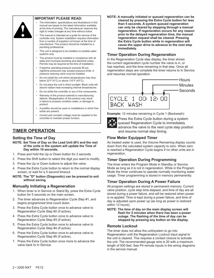
Timer Operation During RegenerationIn the Regeneration Cycle step display, the timer shows the current regeneration cycle number the valve is in, or has reached, and the time remaining in that step. Once all regeneration steps are complete the timer returns to In Service and resumes normal operation.
Example: 12 minutes remaining in Cycle 1 (Backwash)Press the Extra Cycle button during a system queued Regeneration Cycle to immediately advance the valve to the next cycle step position and resume normal step timing.
Flow Meter Equipped TimerAs treated water is used, the Volume Remaining display counts down from the calculated system capacity to zero. When zero is reached a Regeneration Cycle begins if no other units are in regeneration.
Timer Operation During ProgrammingThe timer enters the Program Mode in Standby or Service Mode as long as it is not in regeneration. While in the Program Mode the timer continues to operate normally monitoring water usage. Timer programming is stored in memory permanently.
Timer Operation During A Power FailureAll program settings are stored in permanent memory. Current valve position, cycle step time elapsed, and time of day are all stored during a power failure, and will be restored when power is re-applied. Time is kept during a power failure, and time of day is adjusted upon power up (as long as power is restored within 12 hours).NOTE: The time of day on the main display screen will
flash for 5 minutes when there has been a power outage. The flashing of the time of day can be stopped by pressing any button on the display.
Remote Lockout The timer does not allow the unit/system to go into Regeneration until the Regeneration Lockout Input signal to the unit is cleared. This requires a contact closure to activate the unit. The recommended gauge wire is 20 with a maximum length of 500 feet. See P4 remote inputs in the wiring diagrams in the service manual.
IMPORTANT PLEASE READ: • The information, specifications and illustrations in this
manual are based on the latest information available at the time of printing. The manufacturer reserves the right to make changes at any time without notice.
• This manual is intended as a guide for service of the controller only. System installation requires information from a number of suppliers not known at the time of manufacture. This product should be installed by a plumbing professional.
• This unit is designed to be installed on potable water systems only.
• This product must be installed in compliance with all state and municipal plumbing and electrical codes. Permits may be required at the time of installation.
• If daytime operating pressure exceeds 80 psi, nighttime pressures may exceed pressure limits. A pressure reducing valve must be installed.
• Do not install the unit where temperatures may drop below 32°F (0°C) or above 110°F (43°C).
• Do not place the unit in direct sunlight. Black units will absorb radiant heat increasing internal temperatures.
• Do not strike the controller or any of the components.• Warranty of this product extends to manufacturing
defects. Misapplication of this product may result in failure to properly condition water, or damage to product.
• A prefilter should be used on installations in which free solids are present.
• Correct and constant voltage must be supplied to the controller to maintain proper function.
2 • 3200 NXT FE12
Regeneration Day Override Feature If the Day Override option is turned on and the valve reaches the set Regeneration Day Override value, the Regeneration Cycle starts if no other unit is in Regeneration. If other units are in regeneration, it is added to a regeneration queue. This occurs regardless of the remaining volume available.
WARNING: Transformer must be grounded and ground wire must be terminated to the back plate where grounding label is located before installation.
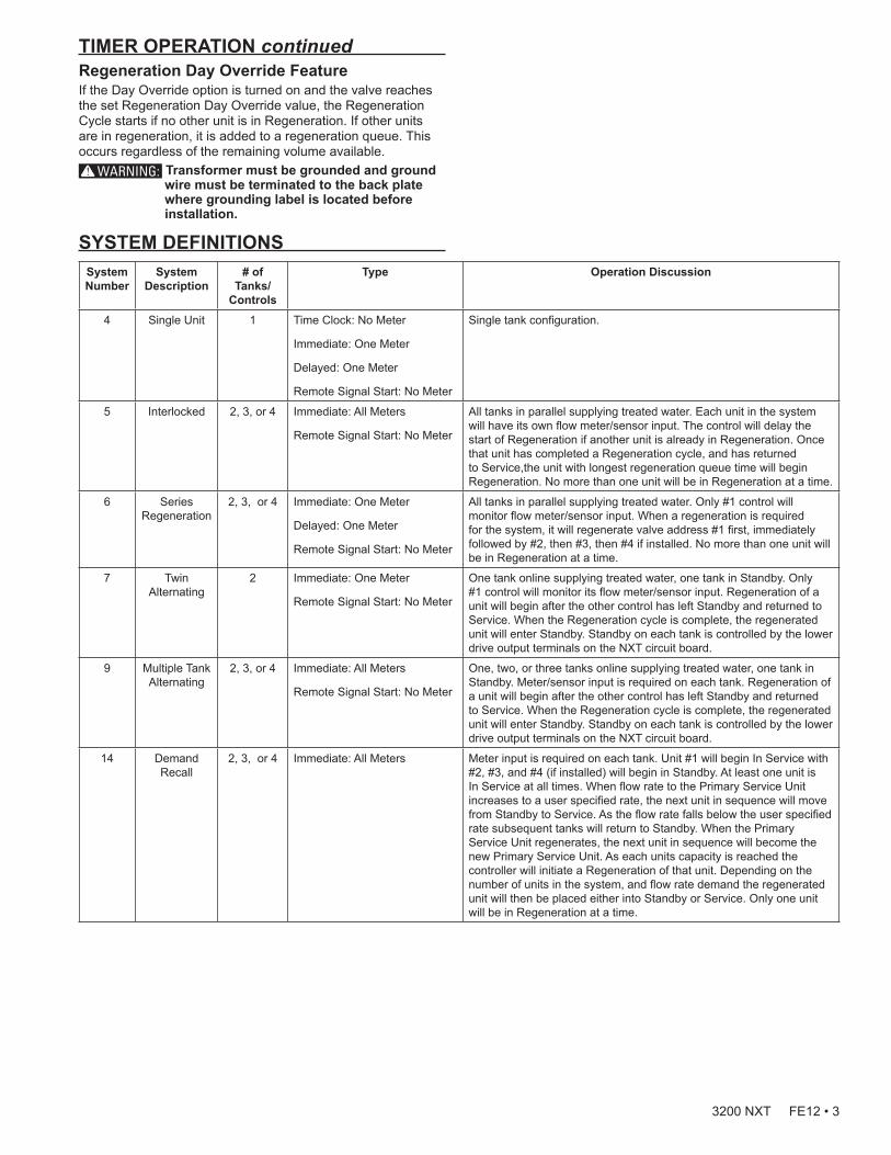
SYSTEM DEFINITIONSSystem Number
System Description
# of Tanks/
Controls
Type Operation Discussion
4 Single Unit 1 Time Clock: No Meter
Immediate: One Meter
Delayed: One Meter
Remote Signal Start: No Meter
Single tank configuration.
5 Interlocked 2, 3, or 4 Immediate: All Meters
Remote Signal Start: No Meter
All tanks in parallel supplying treated water. Each unit in the system will have its own flow meter/sensor input. The control will delay the start of Regeneration if another unit is already in Regeneration. Once that unit has completed a Regeneration cycle, and has returned to Service,the unit with longest regeneration queue time will begin Regeneration. No more than one unit will be in Regeneration at a time.
6 Series Regeneration
2, 3, or 4 Immediate: One Meter
Delayed: One Meter
Remote Signal Start: No Meter
All tanks in parallel supplying treated water. Only #1 control will monitor flow meter/sensor input. When a regeneration is required for the system, it will regenerate valve address #1 first, immediately followed by #2, then #3, then #4 if installed. No more than one unit will be in Regeneration at a time.
7 Twin Alternating
2 Immediate: One Meter
Remote Signal Start: No Meter
One tank online supplying treated water, one tank in Standby. Only #1 control will monitor its flow meter/sensor input. Regeneration of a unit will begin after the other control has left Standby and returned to Service. When the Regeneration cycle is complete, the regenerated unit will enter Standby. Standby on each tank is controlled by the lower drive output terminals on the NXT circuit board.
9 Multiple Tank Alternating
2, 3, or 4 Immediate: All Meters
Remote Signal Start: No Meter
One, two, or three tanks online supplying treated water, one tank in Standby. Meter/sensor input is required on each tank. Regeneration of a unit will begin after the other control has left Standby and returned to Service. When the Regeneration cycle is complete, the regenerated unit will enter Standby. Standby on each tank is controlled by the lower drive output terminals on the NXT circuit board.
14 Demand Recall
2, 3, or 4 Immediate: All Meters Meter input is required on each tank. Unit #1 will begin In Service with #2, #3, and #4 (if installed) will begin in Standby. At least one unit is In Service at all times. When flow rate to the Primary Service Unit increases to a user specified rate, the next unit in sequence will move from Standby to Service. As the flow rate falls below the user specified rate subsequent tanks will return to Standby. When the Primary Service Unit regenerates, the next unit in sequence will become the new Primary Service Unit. As each units capacity is reached the controller will initiate a Regeneration of that unit. Depending on the number of units in the system, and flow rate demand the regenerated unit will then be placed either into Standby or Service. Only one unit will be in Regeneration at a time.
TIMER OPERATION continued
3200 NXT FE12 • 3

SYSTEM OPERATION IN SERVICE (SYSTEM 14-DEMAND RECALL)The system operates as part of a multi-valve regeneration system.Each valve in the system will have an active flow meter input, even in Standby.The number of valves in service depends on the flow rate.
Examples of a Four-Unit System:1. One Valve is in service at all times (the "primary valve").
In Service (Primary Tank) Standby
1 2 3 4
2. The total flow rate to the primary valve increased past the first trip point programmed rate. The flow stayed past the trip point delayed time. The next valve (least volume remaining) changes from Standby to In Service. This valve then splits the total flow between two meters.
In Service
1 2 3 4
StandbyFirst Trip Point (Primary Valve)
Total Flow Split Between Two Meters
3. The flow rate demand decreased below the first trip point. The valve returns to Standby.
Standby
Flow Rate Demand Below First Trip Point
(Primary Valve)
1 2 3 4
4. Total flow rate demand increased past a second trip point programmed rate. The second and third valve (least volume remaining) changes from Standby to In Service. The total flow is split between the three meters.
Standby
Flow Split Between Three Meters
1 2 3 4
5. The third valves returns to stand by as demand decreases past the second trip point.
StandbyFlow Split Between Two Meters
1 2 3 4
6. Valves return to stand by due to decreased total flow rate and trip points programmed. The valve with the most remaining volume will be the first to go into Standby.
Full Capacity 4th in Standby (Primary Valve)
3/4 Capacity 3rd in Standby
1 2 3 4
1/2 Capacity 2nd in Standby
1/4 Capacity 1st in Standby
7. The primary valve regenerates. The next valve with the least remaining volume becomes the new primary valve. The valve with the next least volume remaining will be the first trip point programmed rate. Valves continue operating in this order.
Full Capacity 4th in Standby
3/4 Capacity 3rd in Standby
1 2 3 4
1/2 Capacity First Trip Point
Programmed Rate
1/4 Capacity New Primary Tank
System Operation in Regeneration:
If two valves are In Service and both reach Volume Remaining = 0, the other two valves will shift from Standby to In Service. The lead valve with Volume Remaining = 0 will start regeneration. The second valve with Volume Remaining = 0 will enter Standby. If flow increases past the trip point a third valve needs to enter In Service. The valve in Standby with Volume Remaining = 0 will shift into In Service to maintain a steady flow. Operating for extended periods in this mode may degrade the water quality.
4 • 3200 NXT FE12

FLOW IN A FOUR-UNIT SYTEM (SYSTEM 14-DEMAND RECALL)
In Service In Service
1 2 3 4
Standby Standby
Steady Flow:
Volume Remaining = 0
Volume Remaining = 0
Regeneration (Volume
Remaining = 0)
In Service (Volume
Remaining = 0)
1 2 3 4
In Service In Service
Flow Increases Past the Trip Point:
Regeneration Standby
1 2 3 4
In Service In Service
Flow Stays Steady:
TIMER DISPLAY FEATURES
System Number
Valve Address
Valve State (SBY, SRV, INI, CHG, LCK)
Flow Indicator
Time of Day
Shift ButtonAdjusts Values to the Left
Up Button Adjusts Values Up
Down Button Adjusts Values Down
Volume Remaining
Status LED
Display ScreenTime of Day alternates with Error Screen Example: Valve #, Volume Remaining, Errors
Diagnostic ButtonView Flow Rate, Peak Flow Rate, Totalizer, Hours Between Last Two Regenerations, Hours Since Last Regeneration, Adjustable Volume Remaining, Valve Position, Send & Receive Errors, Software VersionExtra Cycle ButtonCycle Valve in Regeneration/Cycle Programming Steps
Figure 1
Valve StateCHG (Change of State) - CHG will be displayed when the lower drive changes from one state to another in dual piston valves.
INI (Initializing) - INI will display on the screen for 30 to 45 seconds when initializing after a power failure reset or programming.
RGQ (Regeneration Queued) -RGQ indicates that the reserve has been entered in a delayed system and regeneration has been queued. When in the main screen, press the Extra Cycle button to toggle service (SRV) with RGQ.
Service (SRV) - SRV will display when the unit is in service.
LCK (Lock) - Lock will be displayed when the terminal/remote input block P4 on the circuit board is switched to “lock”. See the “Network/Communication Cables & Connections” section of this manual.
LED Status LightsBlue LED - Illuminates while the unit is in service and no errors exist. A blinking blue light indicates the timer is in service, and queued for regeneration.
Green LED - Illuminates when the unit is in Regeneration mode, unless an error condition exists. A blinking green light indicates the timer is in Standby, and not in Regeneration.
Red LED- Illuminates when there is an error.
Flow IndicatorA rotating line (appearing as a rotating star shape) will display on the screen when flow is going through the meter.
TIMER DISPLAY - SCREEN EXAMPLES
3200 NXT FE12 • 5
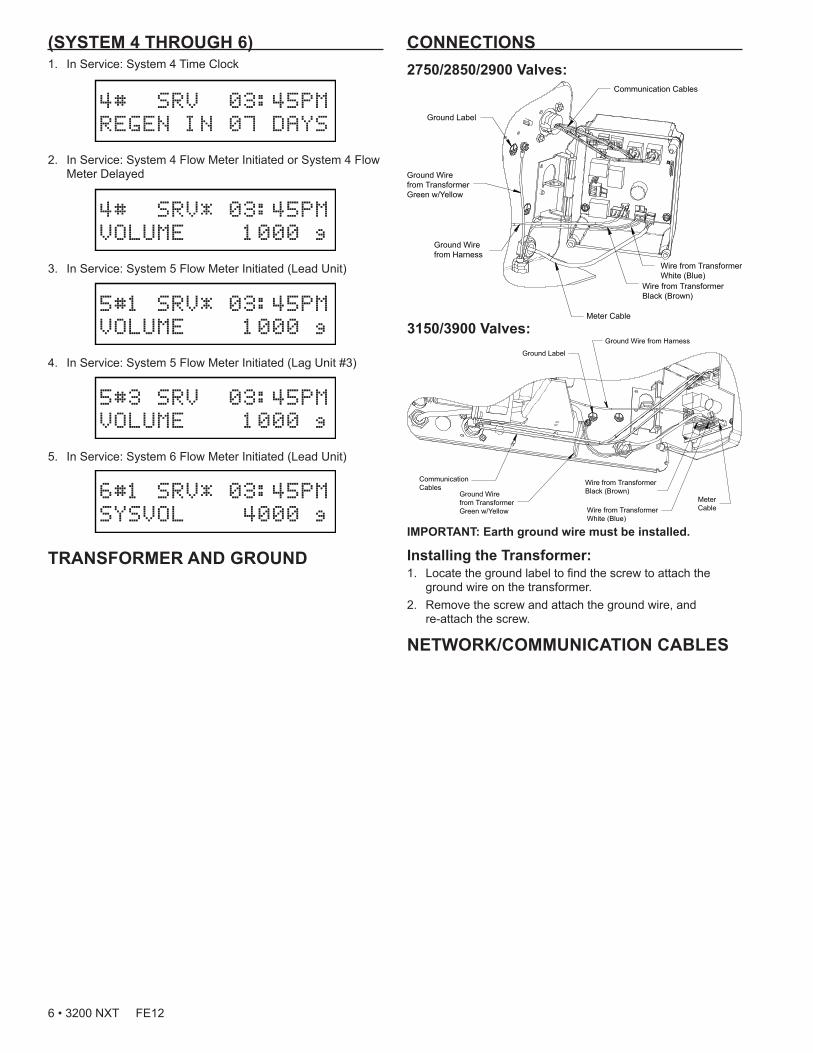
CONNECTIONS2750/2850/2900 Valves:
3150/3900 Valves:
IMPORTANT: Earth ground wire must be installed.
Installing the Transformer:1. Locate the ground label to find the screw to attach the
ground wire on the transformer.2. Remove the screw and attach the ground wire, and
re-attach the screw.
NETWORK/COMMUNICATION CABLES
(SYSTEM 4 THROUGH 6)1. In Service: System 4 Time Clock
4# SRV 03:45PM
REGEN IN 07 DAYS
2. In Service: System 4 Flow Meter Initiated or System 4 Flow Meter Delayed
4# SRV* 03:45PM
VOLUME 1000 g
3. In Service: System 5 Flow Meter Initiated (Lead Unit)
5#1 SRV* 03:45PM
VOLUME 1000 g
4. In Service: System 5 Flow Meter Initiated (Lag Unit #3)
5#3 SRV 03:45PM
VOLUME 1000 g
5. In Service: System 6 Flow Meter Initiated (Lead Unit)
6#1 SRV* 03:45PM
SYSVOL 4000 g
TRANSFORMER AND GROUND
6 • 3200 NXT FE12
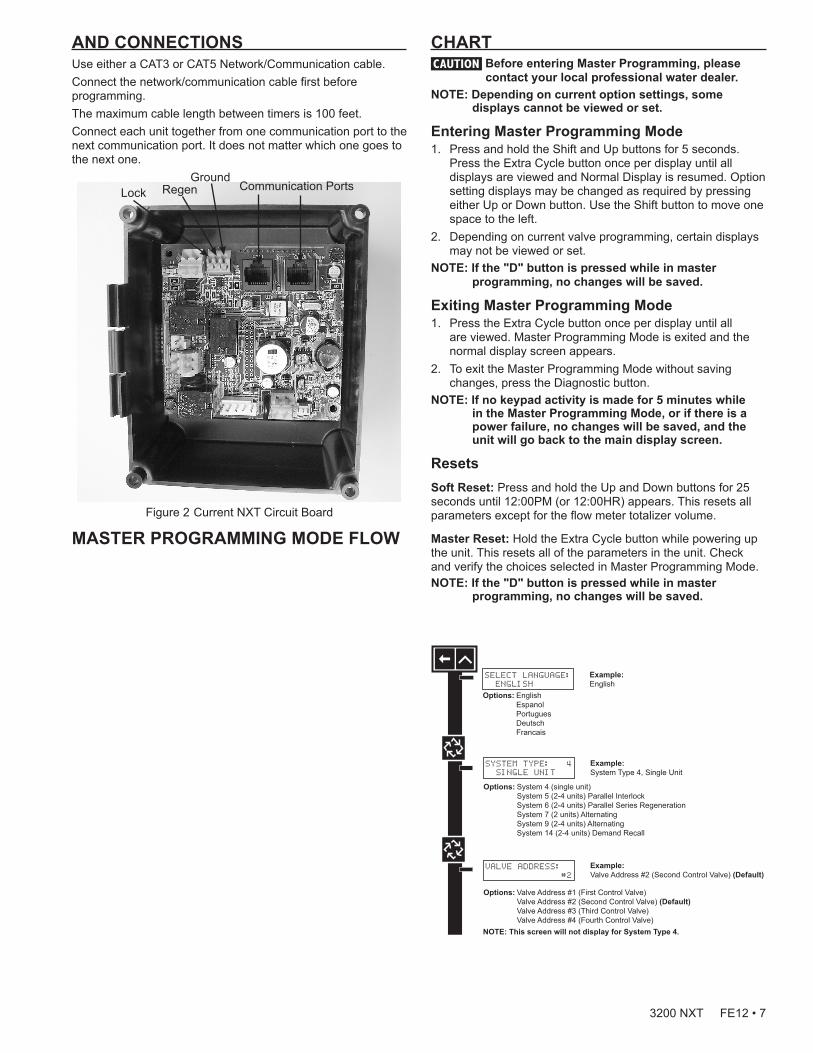
AND CONNECTIONSUse either a CAT3 or CAT5 Network/Communication cable.Connect the network/communication cable first before programming.The maximum cable length between timers is 100 feet.Connect each unit together from one communication port to the next communication port. It does not matter which one goes to the next one.
Communication PortsGround
Lock Regen
Figure 2 Current NXT Circuit Board
MASTER PROGRAMMING MODE FLOW
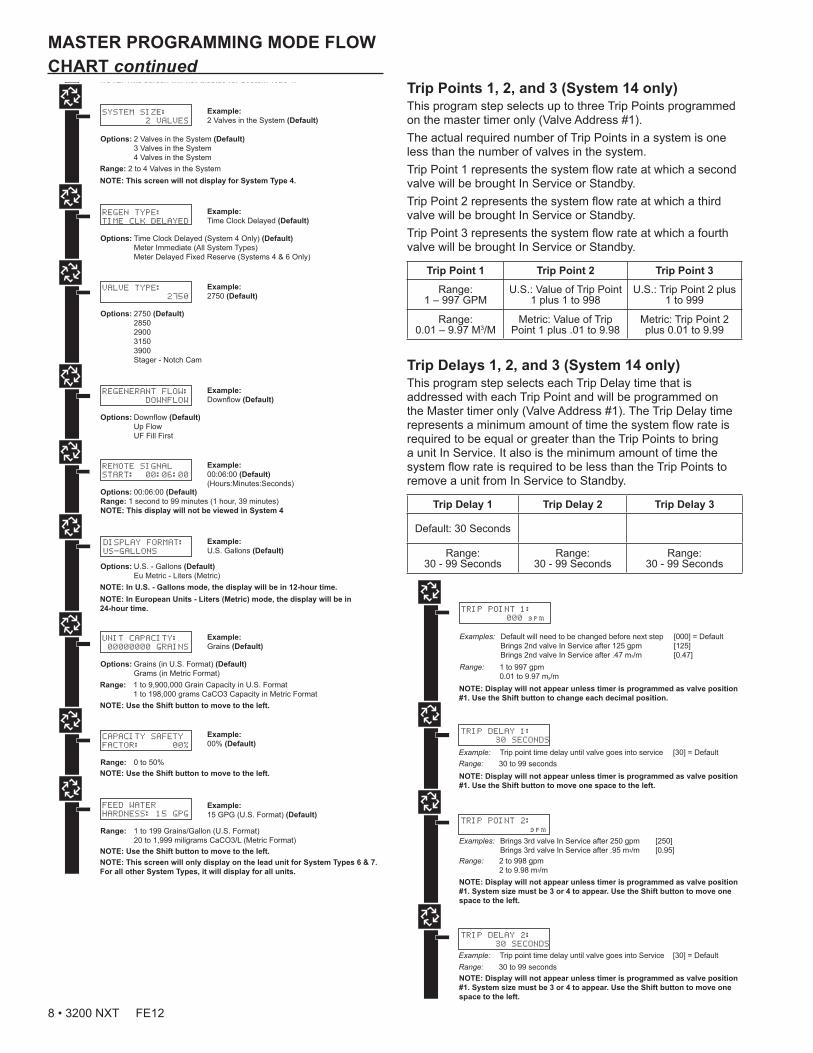
CHARTCAUTION Before entering Master Programming, please
contact your local professional water dealer.NOTE: Depending on current option settings, some
displays cannot be viewed or set.
Entering Master Programming Mode1. Press and hold the Shift and Up buttons for 5 seconds.
Press the Extra Cycle button once per display until all displays are viewed and Normal Display is resumed. Option setting displays may be changed as required by pressing either Up or Down button. Use the Shift button to move one space to the left.
2. Depending on current valve programming, certain displays may not be viewed or set.
NOTE: If the "D" button is pressed while in master programming, no changes will be saved.
Exiting Master Programming Mode1. Press the Extra Cycle button once per display until all
are viewed. Master Programming Mode is exited and the normal display screen appears.
2. To exit the Master Programming Mode without saving changes, press the Diagnostic button.
NOTE: If no keypad activity is made for 5 minutes while in the Master Programming Mode, or if there is a power failure, no changes will be saved, and the unit will go back to the main display screen.
ResetsSoft Reset: Press and hold the Up and Down buttons for 25 seconds until 12:00PM (or 12:00HR) appears. This resets all parameters except for the flow meter totalizer volume.
Master Reset: Hold the Extra Cycle button while powering up the unit. This resets all of the parameters in the unit. Check and verify the choices selected in Master Programming Mode.NOTE: If the "D" button is pressed while in master
programming, no changes will be saved.
VALVE ADDRESS:
#2
Options: Valve Address #1 (First Control Valve) Valve Address #2 (Second Control Valve) (Default) Valve Address #3 (Third Control Valve) Valve Address #4 (Fourth Control Valve)
SYSTEM TYPE: 4
SINGLE UNIT
Options: System 4 (single unit) System 5 (2-4 units) Parallel Interlock System 6 (2-4 units) Parallel Series Regeneration System 7 (2 units) Alternating System 9 (2-4 units) Alternating System 14 (2-4 units) Demand Recall
Example:System Type 4, Single Unit
Example:Valve Address #2 (Second Control Valve) (Default)
Example:U.S. Gallons (Default)
SELECT LANGUAGE:
ENGLISH
Options: English Espanol Portugues Deutsch Francais
Example:English
VALVE TYPE:
2750
Options: 2750 (Default) 2850 2900 3150 3900 Stager - Notch Cam
Example:2750 (Default)
REGEN TYPE:
TIME CLK DELAYED
Options: Time Clock Delayed (System 4 Only) (Default) Meter Immediate (All System Types) Meter Delayed Fixed Reserve (Systems 4 & 6 Only)
Example:Time Clock Delayed (Default)
REGENERANT FLOW:
DOWNFLOW
Options: Downflow (Default) Up Flow UF Fill First
Example:Downflow (Default)
REMOTE SIGNAL
START: 00:06:00
Options: 00:06:00 (Default)Range: 1 second to 99 minutes (1 hour, 39 minutes)NOTE: This display will not be viewed in System 4
Example:00:06:00 (Default)(Hours:Minutes:Seconds)
NOTE: This screen will not display for System Type 4.
SYSTEM SIZE:
2 VALVES
Options: 2 Valves in the System (Default) 3 Valves in the System 4 Valves in the System
Example:2 Valves in the System (Default)
Range: 2 to 4 Valves in the SystemNOTE: This screen will not display for System Type 4.
DISPLAY FORMAT:
US-GALLONS
Options: U.S. - Gallons (Default) Eu Metric - Liters (Metric)
NOTE: In European Units - Liters (Metric) mode, the display will be in 24-hour time.
NOTE: In U.S. - Gallons mode, the display will be in 12-hour time.
UNIT CAPACITY:
00000000 GRAINS
Options: Grains (in U.S. Format) (Default) Grams (in Metric Format)
Example:Grains (Default)
NOTE: Use the Shift button to move to the left.
Range: 1 to 9,900,000 Grain Capacity in U.S. Format 1 to 198,000 grams CaCO3 Capacity in Metric Format
Example:00% (Default)
CAPACITY SAFETY
FACTOR: 00%
Range: 0 to 50%NOTE: Use the Shift button to move to the left.
FEED WATER
HARDNESS: 15 GPG
Range: 1 to 199 Grains/Gallon (U.S. Format) 20 to 1,999 miligrams CaCO3/L (Metric Format)
Example:15 GPG (U.S. Format) (Default)
NOTE: Use the Shift button to move to the left.NOTE: This screen will only display on the lead unit for System Types 6 & 7.For all other System Types, it will display for all units.
TRIP POINT 1:
000 gpm
NOTE: Display will not appear unless timer is programmed as valve position #1. Use the Shift button to change each decimal position.
REGENERATION DAY
OVERRIDE:OFF
Example:Off (Default)On (Default for time clock)
REGENERATION DAY
OVERRIDE:01 DAYS
Options: Off (Default for meter) or On
Example:1 Day
Range: 1 to 99 Days
REGENERATION
TIME: 02:00AM
Example:2:00 A.M. (Default)
Options: A.M. (U.S. Format) HR (Metric Format)NOTE: Regeneration time will not appear unless Regeneration Day Override is on.
CYCLE 1 00:00:00
BACK WASH
Example:Cycle 1 in Back Wash Mode
Options: Regeneration Cycle Step #1 Regeneration Cycle Step #2 Regeneration Cycle Step #3 Regeneration Cycle Step #4 Regeneration Cycle Step #5NOTE: Please refer to the “Regenerant Flow Default Cycle Steps & Times” in the Master Programming Mode section of the manual.NOTE: If Stager is chosen for Valve Type, the Regeneration Cycle Step description will not display.
AUXILIARY RELAY:
DISABLED
Example:Auxiliary Relay is Disabled
Options: Enabled Disabled (Default)
AUX RELAY OUTPUT
START 1 00:00:00
Example:Auxiliary Relay Output in Start 1 at 0 hours, 0 minutes, & 0 seconds
Range: 00:00:00 to 18:00:00NOTE: Only displayed if Auxiliary Relay is enabled in previous screen. Auxiliary Relay will only display if Chemical Pump is OFF for System Types 6 & 7.
AUX RELAY OUTPUT
END 1 00:00:00
Example:Auxiliary Relay Output in End 1 at 0 hours, 0 minutes, & 0 seconds
Range: 00:00:00 to 18:00:00
CHEMICAL PUMP:
DISABLED
Example:Chemical Pump is Disabled
Options: Enabled Disabled (Default)NOTE: This screen will only display on the lead unit for System Types 6 & 7. For all other System Types, it will display for all units.
CPO AUX RELAY
VOLUME: 000 g
Example:Energize Chemical Pump Relay Every 50 GallonsEnergize Chemical Pump Relay Every 200 L
Range: 1 to 999 gallons in U.S. Format 1 to 9.999 L in Metric FormatNOTE: Only displayed on units that physically have a meter (Lead always has a meter). Only shown if Auxiliary Relay is disabled on System Types 6 & 7.
CPO AUX RELAY
TIME: 00:00:00
Example:Each Time the Chemical Pump Relay is on, Run for 30 Seconds (00:00:30)
Range: 00:00:00 to 02:00:00
FLOW METER:
1.0 PADDLE
Example:1.0 Paddle Flow Meter
Options: 1.0 Paddle (Fleck) 1.0 Turbine (Fleck) 1.5 Paddle (Fleck) 1.5 Turbine (Fleck) 2.0 Paddle (Fleck) 3.0 Paddle (Fleck) Generic (Non-Fleck)NOTES: Default flow meter type is based on the valve type. This screen will only display on the lead unit for System Types 6 & 7. All other system types it will display for all units.
MAXIMUM FLOW
RATE: 0000 gpm
Example:Maximum Flow Rate of 0 gpm
Range: 20 - 2,000 gpm (U.S. Format) 20 - 200.0 L (Metric Format) NOTE: Only displayed if “Generic” is chosen for the flow meter.
Range: 1 - 255Gallons (U.S. Format) 0.1 - 09.9 L (Metric Format) Pulses: 1 - 255
Options: Gallons (U.S. Format) Liters (Metric Format)
ADD 01 GALLONS
EVERY 001 PULSES
Example:Add 1 Gallon for Each Pulse in U.S. Format
NOTE: Only displayed if “Generic” is chosen for the flow meter.
PROGRAMMING UNIT
PLEASE WAIT...
Example:Master Programming Mode is Exiting
NOTE: Display will not appear unless timer is programmed as valve position #1. Use the Shift button to move one space to the left.
TRIP DELAY 1:
30 SECONDS
NOTE: Display will not appear unless timer is programmed as valve position #1. System size must be 3 or 4 to appear. Use the Shift button to move one space to the left.
TRIP DELAY 2:
30 SECONDS
NOTE: Display will not appear unless timer is programmed as valve position #1. System size must be 3 or 4 to appear. Use the Shift button to move one space to the left.
TRIP POINT 2:
gpm
NOTE: Display will not appear unless timer is programmed as valve position #1. System size must be 4 to appear. Use the Shift button to move one space to the left.
TRIP POINT 3:
gpm
NOTE: Display will not appear unless timer is programmed as valve position #1. System size must be 4 to appear. Use the Shift button to move one space to the left.
TRIP DELAY 3:
30 SECONDS
3200 NXT FE12 • 7
VALVE ADDRESS:
#2
Options: Valve Address #1 (First Control Valve) Valve Address #2 (Second Control Valve) (Default) Valve Address #3 (Third Control Valve) Valve Address #4 (Fourth Control Valve)
SYSTEM TYPE: 4
SINGLE UNIT
Options: System 4 (single unit) System 5 (2-4 units) Parallel Interlock System 6 (2-4 units) Parallel Series Regeneration System 7 (2 units) Alternating System 9 (2-4 units) Alternating System 14 (2-4 units) Demand Recall
Example:System Type 4, Single Unit
Example:Valve Address #2 (Second Control Valve) (Default)
Example:U.S. Gallons (Default)
SELECT LANGUAGE:
ENGLISH
Options: English Espanol Portugues Deutsch Francais
Example:English
VALVE TYPE:
2750
Options: 2750 (Default) 2850 2900 3150 3900 Stager - Notch Cam
Example:2750 (Default)
REGEN TYPE:
TIME CLK DELAYED
Options: Time Clock Delayed (System 4 Only) (Default) Meter Immediate (All System Types) Meter Delayed Fixed Reserve (Systems 4 & 6 Only)
Example:Time Clock Delayed (Default)
REGENERANT FLOW:
DOWNFLOW
Options: Downflow (Default) Up Flow UF Fill First
Example:Downflow (Default)
REMOTE SIGNAL
START: 00:06:00
Options: 00:06:00 (Default)Range: 1 second to 99 minutes (1 hour, 39 minutes)NOTE: This display will not be viewed in System 4
Example:00:06:00 (Default)(Hours:Minutes:Seconds)
NOTE: This screen will not display for System Type 4.
SYSTEM SIZE:
2 VALVES
Options: 2 Valves in the System (Default) 3 Valves in the System 4 Valves in the System
Example:2 Valves in the System (Default)
Range: 2 to 4 Valves in the SystemNOTE: This screen will not display for System Type 4.
DISPLAY FORMAT:
US-GALLONS
Options: U.S. - Gallons (Default) Eu Metric - Liters (Metric)
NOTE: In European Units - Liters (Metric) mode, the display will be in 24-hour time.
NOTE: In U.S. - Gallons mode, the display will be in 12-hour time.
UNIT CAPACITY:
00000000 GRAINS
Options: Grains (in U.S. Format) (Default) Grams (in Metric Format)
Example:Grains (Default)
NOTE: Use the Shift button to move to the left.
Range: 1 to 9,900,000 Grain Capacity in U.S. Format 1 to 198,000 grams CaCO3 Capacity in Metric Format
Example:00% (Default)
CAPACITY SAFETY
FACTOR: 00%
Range: 0 to 50%NOTE: Use the Shift button to move to the left.
FEED WATER
HARDNESS: 15 GPG
Range: 1 to 199 Grains/Gallon (U.S. Format) 20 to 1,999 miligrams CaCO3/L (Metric Format)
Example:15 GPG (U.S. Format) (Default)
NOTE: Use the Shift button to move to the left.NOTE: This screen will only display on the lead unit for System Types 6 & 7.For all other System Types, it will display for all units.
TRIP POINT 1:
000 gpm
NOTE: Display will not appear unless timer is programmed as valve position #1. Use the Shift button to change each decimal position.
REGENERATION DAY
OVERRIDE:OFF
Example:Off (Default)On (Default for time clock)
REGENERATION DAY
OVERRIDE:01 DAYS
Options: Off (Default for meter) or On
Example:1 Day
Range: 1 to 99 Days
REGENERATION
TIME: 02:00AM
Example:2:00 A.M. (Default)
Options: A.M. (U.S. Format) HR (Metric Format)NOTE: Regeneration time will not appear unless Regeneration Day Override is on.
CYCLE 1 00:00:00
BACK WASH
Example:Cycle 1 in Back Wash Mode
Options: Regeneration Cycle Step #1 Regeneration Cycle Step #2 Regeneration Cycle Step #3 Regeneration Cycle Step #4 Regeneration Cycle Step #5NOTE: Please refer to the “Regenerant Flow Default Cycle Steps & Times” in the Master Programming Mode section of the manual.NOTE: If Stager is chosen for Valve Type, the Regeneration Cycle Step description will not display.
AUXILIARY RELAY:
DISABLED
Example:Auxiliary Relay is Disabled
Options: Enabled Disabled (Default)
AUX RELAY OUTPUT
START 1 00:00:00
Example:Auxiliary Relay Output in Start 1 at 0 hours, 0 minutes, & 0 seconds
Range: 00:00:00 to 18:00:00NOTE: Only displayed if Auxiliary Relay is enabled in previous screen. Auxiliary Relay will only display if Chemical Pump is OFF for System Types 6 & 7.
AUX RELAY OUTPUT
END 1 00:00:00
Example:Auxiliary Relay Output in End 1 at 0 hours, 0 minutes, & 0 seconds
Range: 00:00:00 to 18:00:00
CHEMICAL PUMP:
DISABLED
Example:Chemical Pump is Disabled
Options: Enabled Disabled (Default)NOTE: This screen will only display on the lead unit for System Types 6 & 7. For all other System Types, it will display for all units.
CPO AUX RELAY
VOLUME: 000 g
Example:Energize Chemical Pump Relay Every 50 GallonsEnergize Chemical Pump Relay Every 200 L
Range: 1 to 999 gallons in U.S. Format 1 to 9.999 L in Metric FormatNOTE: Only displayed on units that physically have a meter (Lead always has a meter). Only shown if Auxiliary Relay is disabled on System Types 6 & 7.
CPO AUX RELAY
TIME: 00:00:00
Example:Each Time the Chemical Pump Relay is on, Run for 30 Seconds (00:00:30)
Range: 00:00:00 to 02:00:00
FLOW METER:
1.0 PADDLE
Example:1.0 Paddle Flow Meter
Options: 1.0 Paddle (Fleck) 1.0 Turbine (Fleck) 1.5 Paddle (Fleck) 1.5 Turbine (Fleck) 2.0 Paddle (Fleck) 3.0 Paddle (Fleck) Generic (Non-Fleck)NOTES: Default flow meter type is based on the valve type. This screen will only display on the lead unit for System Types 6 & 7. All other system types it will display for all units.
MAXIMUM FLOW
RATE: 0000 gpm
Example:Maximum Flow Rate of 0 gpm
Range: 20 - 2,000 gpm (U.S. Format) 20 - 200.0 L (Metric Format) NOTE: Only displayed if “Generic” is chosen for the flow meter.
Range: 1 - 255Gallons (U.S. Format) 0.1 - 09.9 L (Metric Format) Pulses: 1 - 255
Options: Gallons (U.S. Format) Liters (Metric Format)
ADD 01 GALLONS
EVERY 001 PULSES
Example:Add 1 Gallon for Each Pulse in U.S. Format
NOTE: Only displayed if “Generic” is chosen for the flow meter.
PROGRAMMING UNIT
PLEASE WAIT...
Example:Master Programming Mode is Exiting
NOTE: Display will not appear unless timer is programmed as valve position #1. Use the Shift button to move one space to the left.
TRIP DELAY 1:
30 SECONDS
NOTE: Display will not appear unless timer is programmed as valve position #1. System size must be 3 or 4 to appear. Use the Shift button to move one space to the left.
TRIP DELAY 2:
30 SECONDS
NOTE: Display will not appear unless timer is programmed as valve position #1. System size must be 3 or 4 to appear. Use the Shift button to move one space to the left.
TRIP POINT 2:
gpm
NOTE: Display will not appear unless timer is programmed as valve position #1. System size must be 4 to appear. Use the Shift button to move one space to the left.
TRIP POINT 3:
gpm
NOTE: Display will not appear unless timer is programmed as valve position #1. System size must be 4 to appear. Use the Shift button to move one space to the left.
TRIP DELAY 3:
30 SECONDS
MASTER PROGRAMMING MODE FLOW CHART continued
VALVE ADDRESS:
#2
Options: Valve Address #1 (First Control Valve) Valve Address #2 (Second Control Valve) (Default) Valve Address #3 (Third Control Valve) Valve Address #4 (Fourth Control Valve)
SYSTEM TYPE: 4
SINGLE UNIT
Options: System 4 (single unit) System 5 (2-4 units) Parallel Interlock System 6 (2-4 units) Parallel Series Regeneration System 7 (2 units) Alternating System 9 (2-4 units) Alternating System 14 (2-4 units) Demand Recall
Example:System Type 4, Single Unit
Example:Valve Address #2 (Second Control Valve) (Default)
Example:U.S. Gallons (Default)
SELECT LANGUAGE:
ENGLISH
Options: English Espanol Portugues Deutsch Francais
Example:English
VALVE TYPE:
2750
Options: 2750 (Default) 2850 2900 3150 3900 Stager - Notch Cam
Example:2750 (Default)
REGEN TYPE:
TIME CLK DELAYED
Options: Time Clock Delayed (System 4 Only) (Default) Meter Immediate (All System Types) Meter Delayed Fixed Reserve (Systems 4 & 6 Only)
Example:Time Clock Delayed (Default)
REGENERANT FLOW:
DOWNFLOW
Options: Downflow (Default) Up Flow UF Fill First
Example:Downflow (Default)
REMOTE SIGNAL
START: 00:06:00
Options: 00:06:00 (Default)Range: 1 second to 99 minutes (1 hour, 39 minutes)NOTE: This display will not be viewed in System 4
Example:00:06:00 (Default)(Hours:Minutes:Seconds)
NOTE: This screen will not display for System Type 4.
SYSTEM SIZE:
2 VALVES
Options: 2 Valves in the System (Default) 3 Valves in the System 4 Valves in the System
Example:2 Valves in the System (Default)
Range: 2 to 4 Valves in the SystemNOTE: This screen will not display for System Type 4.
DISPLAY FORMAT:
US-GALLONS
Options: U.S. - Gallons (Default) Eu Metric - Liters (Metric)
NOTE: In European Units - Liters (Metric) mode, the display will be in 24-hour time.
NOTE: In U.S. - Gallons mode, the display will be in 12-hour time.
UNIT CAPACITY:
00000000 GRAINS
Options: Grains (in U.S. Format) (Default) Grams (in Metric Format)
Example:Grains (Default)
NOTE: Use the Shift button to move to the left.
Range: 1 to 9,900,000 Grain Capacity in U.S. Format 1 to 198,000 grams CaCO3 Capacity in Metric Format
Example:00% (Default)
CAPACITY SAFETY
FACTOR: 00%
Range: 0 to 50%NOTE: Use the Shift button to move to the left.
FEED WATER
HARDNESS: 15 GPG
Range: 1 to 199 Grains/Gallon (U.S. Format) 20 to 1,999 miligrams CaCO3/L (Metric Format)
Example:15 GPG (U.S. Format) (Default)
NOTE: Use the Shift button to move to the left.NOTE: This screen will only display on the lead unit for System Types 6 & 7.For all other System Types, it will display for all units.
TRIP POINT 1:
000 gpm
NOTE: Display will not appear unless timer is programmed as valve position #1. Use the Shift button to change each decimal position.
REGENERATION DAY
OVERRIDE:OFF
Example:Off (Default)On (Default for time clock)
REGENERATION DAY
OVERRIDE:01 DAYS
Options: Off (Default for meter) or On
Example:1 Day
Range: 1 to 99 Days
REGENERATION
TIME: 02:00AM
Example:2:00 A.M. (Default)
Options: A.M. (U.S. Format) HR (Metric Format)NOTE: Regeneration time will not appear unless Regeneration Day Override is on.
CYCLE 1 00:00:00
BACK WASH
Example:Cycle 1 in Back Wash Mode
Options: Regeneration Cycle Step #1 Regeneration Cycle Step #2 Regeneration Cycle Step #3 Regeneration Cycle Step #4 Regeneration Cycle Step #5NOTE: Please refer to the “Regenerant Flow Default Cycle Steps & Times” in the Master Programming Mode section of the manual.NOTE: If Stager is chosen for Valve Type, the Regeneration Cycle Step description will not display.
AUXILIARY RELAY:
DISABLED
Example:Auxiliary Relay is Disabled
Options: Enabled Disabled (Default)
AUX RELAY OUTPUT
START 1 00:00:00
Example:Auxiliary Relay Output in Start 1 at 0 hours, 0 minutes, & 0 seconds
Range: 00:00:00 to 18:00:00NOTE: Only displayed if Auxiliary Relay is enabled in previous screen. Auxiliary Relay will only display if Chemical Pump is OFF for System Types 6 & 7.
AUX RELAY OUTPUT
END 1 00:00:00
Example:Auxiliary Relay Output in End 1 at 0 hours, 0 minutes, & 0 seconds
Range: 00:00:00 to 18:00:00
CHEMICAL PUMP:
DISABLED
Example:Chemical Pump is Disabled
Options: Enabled Disabled (Default)NOTE: This screen will only display on the lead unit for System Types 6 & 7. For all other System Types, it will display for all units.
CPO AUX RELAY
VOLUME: 000 g
Example:Energize Chemical Pump Relay Every 50 GallonsEnergize Chemical Pump Relay Every 200 L
Range: 1 to 999 gallons in U.S. Format 1 to 9.999 L in Metric FormatNOTE: Only displayed on units that physically have a meter (Lead always has a meter). Only shown if Auxiliary Relay is disabled on System Types 6 & 7.
CPO AUX RELAY
TIME: 00:00:00
Example:Each Time the Chemical Pump Relay is on, Run for 30 Seconds (00:00:30)
Range: 00:00:00 to 02:00:00
FLOW METER:
1.0 PADDLE
Example:1.0 Paddle Flow Meter
Options: 1.0 Paddle (Fleck) 1.0 Turbine (Fleck) 1.5 Paddle (Fleck) 1.5 Turbine (Fleck) 2.0 Paddle (Fleck) 3.0 Paddle (Fleck) Generic (Non-Fleck)NOTES: Default flow meter type is based on the valve type. This screen will only display on the lead unit for System Types 6 & 7. All other system types it will display for all units.
MAXIMUM FLOW
RATE: 0000 gpm
Example:Maximum Flow Rate of 0 gpm
Range: 20 - 2,000 gpm (U.S. Format) 20 - 200.0 L (Metric Format) NOTE: Only displayed if “Generic” is chosen for the flow meter.
Range: 1 - 255Gallons (U.S. Format) 0.1 - 09.9 L (Metric Format) Pulses: 1 - 255
Options: Gallons (U.S. Format) Liters (Metric Format)
ADD 01 GALLONS
EVERY 001 PULSES
Example:Add 1 Gallon for Each Pulse in U.S. Format
NOTE: Only displayed if “Generic” is chosen for the flow meter.
PROGRAMMING UNIT
PLEASE WAIT...
Example:Master Programming Mode is Exiting
NOTE: Display will not appear unless timer is programmed as valve position #1. Use the Shift button to move one space to the left.
TRIP DELAY 1:
30 SECONDS
NOTE: Display will not appear unless timer is programmed as valve position #1. System size must be 3 or 4 to appear. Use the Shift button to move one space to the left.
TRIP DELAY 2:
30 SECONDS
NOTE: Display will not appear unless timer is programmed as valve position #1. System size must be 3 or 4 to appear. Use the Shift button to move one space to the left.
TRIP POINT 2:
gpm
NOTE: Display will not appear unless timer is programmed as valve position #1. System size must be 4 to appear. Use the Shift button to move one space to the left.
TRIP POINT 3:
gpm
NOTE: Display will not appear unless timer is programmed as valve position #1. System size must be 4 to appear. Use the Shift button to move one space to the left.
TRIP DELAY 3:
30 SECONDS
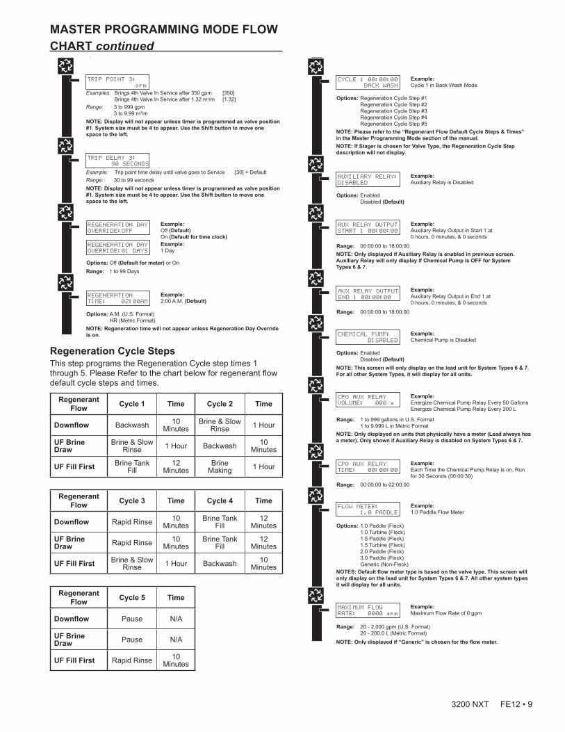
Trip Points 1, 2, and 3 (System 14 only)This program step selects up to three Trip Points programmed on the master timer only (Valve Address #1).The actual required number of Trip Points in a system is one less than the number of valves in the system.Trip Point 1 represents the system flow rate at which a second valve will be brought In Service or Standby.Trip Point 2 represents the system flow rate at which a third valve will be brought In Service or Standby. Trip Point 3 represents the system flow rate at which a fourth valve will be brought In Service or Standby.
Trip Point 1 Trip Point 2 Trip Point 3
Range: 1 – 997 GPM
U.S.: Value of Trip Point 1 plus 1 to 998
U.S.: Trip Point 2 plus 1 to 999
Range: 0.01 – 9.97 M3/M
Metric: Value of Trip Point 1 plus .01 to 9.98
Metric: Trip Point 2 plus 0.01 to 9.99
Trip Delays 1, 2, and 3 (System 14 only)This program step selects each Trip Delay time that is addressed with each Trip Point and will be programmed on the Master timer only (Valve Address #1). The Trip Delay time represents a minimum amount of time the system flow rate is required to be equal or greater than the Trip Points to bring a unit In Service. It also is the minimum amount of time the system flow rate is required to be less than the Trip Points to remove a unit from In Service to Standby.
Trip Delay 1 Trip Delay 2 Trip Delay 3
Default: 30 Seconds
Range: 30 - 99 Seconds
Range: 30 - 99 Seconds
Range: 30 - 99 Seconds
8 • 3200 NXT FE12
VALVE ADDRESS:
#2
Options: Valve Address #1 (First Control Valve) Valve Address #2 (Second Control Valve) (Default) Valve Address #3 (Third Control Valve) Valve Address #4 (Fourth Control Valve)
SYSTEM TYPE: 4
SINGLE UNIT
Options: System 4 (single unit) System 5 (2-4 units) Parallel Interlock System 6 (2-4 units) Parallel Series Regeneration System 7 (2 units) Alternating System 9 (2-4 units) Alternating System 14 (2-4 units) Demand Recall
Example:System Type 4, Single Unit
Example:Valve Address #2 (Second Control Valve) (Default)
Example:U.S. Gallons (Default)
SELECT LANGUAGE:
ENGLISH
Options: English Espanol Portugues Deutsch Francais
Example:English
VALVE TYPE:
2750
Options: 2750 (Default) 2850 2900 3150 3900 Stager - Notch Cam
Example:2750 (Default)
REGEN TYPE:
TIME CLK DELAYED
Options: Time Clock Delayed (System 4 Only) (Default) Meter Immediate (All System Types) Meter Delayed Fixed Reserve (Systems 4 & 6 Only)
Example:Time Clock Delayed (Default)
REGENERANT FLOW:
DOWNFLOW
Options: Downflow (Default) Up Flow UF Fill First
Example:Downflow (Default)
REMOTE SIGNAL
START: 00:06:00
Options: 00:06:00 (Default)Range: 1 second to 99 minutes (1 hour, 39 minutes)NOTE: This display will not be viewed in System 4
Example:00:06:00 (Default)(Hours:Minutes:Seconds)
NOTE: This screen will not display for System Type 4.
SYSTEM SIZE:
2 VALVES
Options: 2 Valves in the System (Default) 3 Valves in the System 4 Valves in the System
Example:2 Valves in the System (Default)
Range: 2 to 4 Valves in the SystemNOTE: This screen will not display for System Type 4.
DISPLAY FORMAT:
US-GALLONS
Options: U.S. - Gallons (Default) Eu Metric - Liters (Metric)
NOTE: In European Units - Liters (Metric) mode, the display will be in 24-hour time.
NOTE: In U.S. - Gallons mode, the display will be in 12-hour time.
UNIT CAPACITY:
00000000 GRAINS
Options: Grains (in U.S. Format) (Default) Grams (in Metric Format)
Example:Grains (Default)
NOTE: Use the Shift button to move to the left.
Range: 1 to 9,900,000 Grain Capacity in U.S. Format 1 to 198,000 grams CaCO3 Capacity in Metric Format
Example:00% (Default)
CAPACITY SAFETY
FACTOR: 00%
Range: 0 to 50%NOTE: Use the Shift button to move to the left.
FEED WATER
HARDNESS: 15 GPG
Range: 1 to 199 Grains/Gallon (U.S. Format) 20 to 1,999 miligrams CaCO3/L (Metric Format)
Example:15 GPG (U.S. Format) (Default)
NOTE: Use the Shift button to move to the left.NOTE: This screen will only display on the lead unit for System Types 6 & 7.For all other System Types, it will display for all units.
TRIP POINT 1:
000 gpm
NOTE: Display will not appear unless timer is programmed as valve position #1. Use the Shift button to change each decimal position.
REGENERATION DAY
OVERRIDE:OFF
Example:Off (Default)On (Default for time clock)
REGENERATION DAY
OVERRIDE:01 DAYS
Options: Off (Default for meter) or On
Example:1 Day
Range: 1 to 99 Days
REGENERATION
TIME: 02:00AM
Example:2:00 A.M. (Default)
Options: A.M. (U.S. Format) HR (Metric Format)NOTE: Regeneration time will not appear unless Regeneration Day Override is on.
CYCLE 1 00:00:00
BACK WASH
Example:Cycle 1 in Back Wash Mode
Options: Regeneration Cycle Step #1 Regeneration Cycle Step #2 Regeneration Cycle Step #3 Regeneration Cycle Step #4 Regeneration Cycle Step #5NOTE: Please refer to the “Regenerant Flow Default Cycle Steps & Times” in the Master Programming Mode section of the manual.NOTE: If Stager is chosen for Valve Type, the Regeneration Cycle Step description will not display.
AUXILIARY RELAY:
DISABLED
Example:Auxiliary Relay is Disabled
Options: Enabled Disabled (Default)
AUX RELAY OUTPUT
START 1 00:00:00
Example:Auxiliary Relay Output in Start 1 at 0 hours, 0 minutes, & 0 seconds
Range: 00:00:00 to 18:00:00NOTE: Only displayed if Auxiliary Relay is enabled in previous screen. Auxiliary Relay will only display if Chemical Pump is OFF for System Types 6 & 7.
AUX RELAY OUTPUT
END 1 00:00:00
Example:Auxiliary Relay Output in End 1 at 0 hours, 0 minutes, & 0 seconds
Range: 00:00:00 to 18:00:00
CHEMICAL PUMP:
DISABLED
Example:Chemical Pump is Disabled
Options: Enabled Disabled (Default)NOTE: This screen will only display on the lead unit for System Types 6 & 7. For all other System Types, it will display for all units.
CPO AUX RELAY
VOLUME: 000 g
Example:Energize Chemical Pump Relay Every 50 GallonsEnergize Chemical Pump Relay Every 200 L
Range: 1 to 999 gallons in U.S. Format 1 to 9.999 L in Metric FormatNOTE: Only displayed on units that physically have a meter (Lead always has a meter). Only shown if Auxiliary Relay is disabled on System Types 6 & 7.
CPO AUX RELAY
TIME: 00:00:00
Example:Each Time the Chemical Pump Relay is on, Run for 30 Seconds (00:00:30)
Range: 00:00:00 to 02:00:00
FLOW METER:
1.0 PADDLE
Example:1.0 Paddle Flow Meter
Options: 1.0 Paddle (Fleck) 1.0 Turbine (Fleck) 1.5 Paddle (Fleck) 1.5 Turbine (Fleck) 2.0 Paddle (Fleck) 3.0 Paddle (Fleck) Generic (Non-Fleck)NOTES: Default flow meter type is based on the valve type. This screen will only display on the lead unit for System Types 6 & 7. All other system types it will display for all units.
MAXIMUM FLOW
RATE: 0000 gpm
Example:Maximum Flow Rate of 0 gpm
Range: 20 - 2,000 gpm (U.S. Format) 20 - 200.0 L (Metric Format) NOTE: Only displayed if “Generic” is chosen for the flow meter.
Range: 1 - 255Gallons (U.S. Format) 0.1 - 09.9 L (Metric Format) Pulses: 1 - 255
Options: Gallons (U.S. Format) Liters (Metric Format)
ADD 01 GALLONS
EVERY 001 PULSES
Example:Add 1 Gallon for Each Pulse in U.S. Format
NOTE: Only displayed if “Generic” is chosen for the flow meter.
PROGRAMMING UNIT
PLEASE WAIT...
Example:Master Programming Mode is Exiting
NOTE: Display will not appear unless timer is programmed as valve position #1. Use the Shift button to move one space to the left.
TRIP DELAY 1:
30 SECONDS
NOTE: Display will not appear unless timer is programmed as valve position #1. System size must be 3 or 4 to appear. Use the Shift button to move one space to the left.
TRIP DELAY 2:
30 SECONDS
NOTE: Display will not appear unless timer is programmed as valve position #1. System size must be 3 or 4 to appear. Use the Shift button to move one space to the left.
TRIP POINT 2:
gpm
NOTE: Display will not appear unless timer is programmed as valve position #1. System size must be 4 to appear. Use the Shift button to move one space to the left.
TRIP POINT 3:
gpm
NOTE: Display will not appear unless timer is programmed as valve position #1. System size must be 4 to appear. Use the Shift button to move one space to the left.
TRIP DELAY 3:
30 SECONDS
Regeneration Cycle StepsThis step programs the Regeneration Cycle step times 1 through 5. Please Refer to the chart below for regenerant flow default cycle steps and times.
Regenerant Flow Cycle 1 Time Cycle 2 Time
Downflow Backwash 10 Minutes
Brine & Slow Rinse 1 Hour
UF Brine Draw
Brine & Slow Rinse 1 Hour Backwash 10
Minutes
UF Fill First Brine Tank Fill
12 Minutes
Brine Making 1 Hour
Regenerant Flow Cycle 3 Time Cycle 4 Time
Downflow Rapid Rinse 10 Minutes
Brine Tank Fill
12 Minutes
UF Brine Draw Rapid Rinse 10
MinutesBrine Tank
Fill12
Minutes
UF Fill First Brine & Slow Rinse 1 Hour Backwash 10
Minutes
Regenerant Flow Cycle 5 Time
Downflow Pause N/A
UF Brine Draw Pause N/A
UF Fill First Rapid Rinse 10 Minutes
MASTER PROGRAMMING MODE FLOW CHART continued
VALVE ADDRESS:
#2
Options: Valve Address #1 (First Control Valve) Valve Address #2 (Second Control Valve) (Default) Valve Address #3 (Third Control Valve) Valve Address #4 (Fourth Control Valve)
SYSTEM TYPE: 4
SINGLE UNIT
Options: System 4 (single unit) System 5 (2-4 units) Parallel Interlock System 6 (2-4 units) Parallel Series Regeneration System 7 (2 units) Alternating System 9 (2-4 units) Alternating System 14 (2-4 units) Demand Recall
Example:System Type 4, Single Unit
Example:Valve Address #2 (Second Control Valve) (Default)
Example:U.S. Gallons (Default)
SELECT LANGUAGE:
ENGLISH
Options: English Espanol Portugues Deutsch Francais
Example:English
VALVE TYPE:
2750
Options: 2750 (Default) 2850 2900 3150 3900 Stager - Notch Cam
Example:2750 (Default)
REGEN TYPE:
TIME CLK DELAYED
Options: Time Clock Delayed (System 4 Only) (Default) Meter Immediate (All System Types) Meter Delayed Fixed Reserve (Systems 4 & 6 Only)
Example:Time Clock Delayed (Default)
REGENERANT FLOW:
DOWNFLOW
Options: Downflow (Default) Up Flow UF Fill First
Example:Downflow (Default)
REMOTE SIGNAL
START: 00:06:00
Options: 00:06:00 (Default)Range: 1 second to 99 minutes (1 hour, 39 minutes)NOTE: This display will not be viewed in System 4
Example:00:06:00 (Default)(Hours:Minutes:Seconds)
NOTE: This screen will not display for System Type 4.
SYSTEM SIZE:
2 VALVES
Options: 2 Valves in the System (Default) 3 Valves in the System 4 Valves in the System
Example:2 Valves in the System (Default)
Range: 2 to 4 Valves in the SystemNOTE: This screen will not display for System Type 4.
DISPLAY FORMAT:
US-GALLONS
Options: U.S. - Gallons (Default) Eu Metric - Liters (Metric)
NOTE: In European Units - Liters (Metric) mode, the display will be in 24-hour time.
NOTE: In U.S. - Gallons mode, the display will be in 12-hour time.
UNIT CAPACITY:
00000000 GRAINS
Options: Grains (in U.S. Format) (Default) Grams (in Metric Format)
Example:Grains (Default)
NOTE: Use the Shift button to move to the left.
Range: 1 to 9,900,000 Grain Capacity in U.S. Format 1 to 198,000 grams CaCO3 Capacity in Metric Format
Example:00% (Default)
CAPACITY SAFETY
FACTOR: 00%
Range: 0 to 50%NOTE: Use the Shift button to move to the left.
FEED WATER
HARDNESS: 15 GPG
Range: 1 to 199 Grains/Gallon (U.S. Format) 20 to 1,999 miligrams CaCO3/L (Metric Format)
Example:15 GPG (U.S. Format) (Default)
NOTE: Use the Shift button to move to the left.NOTE: This screen will only display on the lead unit for System Types 6 & 7.For all other System Types, it will display for all units.
TRIP POINT 1:
000 gpm
NOTE: Display will not appear unless timer is programmed as valve position #1. Use the Shift button to change each decimal position.
REGENERATION DAY
OVERRIDE:OFF
Example:Off (Default)On (Default for time clock)
REGENERATION DAY
OVERRIDE:01 DAYS
Options: Off (Default for meter) or On
Example:1 Day
Range: 1 to 99 Days
REGENERATION
TIME: 02:00AM
Example:2:00 A.M. (Default)
Options: A.M. (U.S. Format) HR (Metric Format)NOTE: Regeneration time will not appear unless Regeneration Day Override is on.
CYCLE 1 00:00:00
BACK WASH
Example:Cycle 1 in Back Wash Mode
Options: Regeneration Cycle Step #1 Regeneration Cycle Step #2 Regeneration Cycle Step #3 Regeneration Cycle Step #4 Regeneration Cycle Step #5NOTE: Please refer to the “Regenerant Flow Default Cycle Steps & Times” in the Master Programming Mode section of the manual.NOTE: If Stager is chosen for Valve Type, the Regeneration Cycle Step description will not display.
AUXILIARY RELAY:
DISABLED
Example:Auxiliary Relay is Disabled
Options: Enabled Disabled (Default)
AUX RELAY OUTPUT
START 1 00:00:00
Example:Auxiliary Relay Output in Start 1 at 0 hours, 0 minutes, & 0 seconds
Range: 00:00:00 to 18:00:00NOTE: Only displayed if Auxiliary Relay is enabled in previous screen. Auxiliary Relay will only display if Chemical Pump is OFF for System Types 6 & 7.
AUX RELAY OUTPUT
END 1 00:00:00
Example:Auxiliary Relay Output in End 1 at 0 hours, 0 minutes, & 0 seconds
Range: 00:00:00 to 18:00:00
CHEMICAL PUMP:
DISABLED
Example:Chemical Pump is Disabled
Options: Enabled Disabled (Default)NOTE: This screen will only display on the lead unit for System Types 6 & 7. For all other System Types, it will display for all units.
CPO AUX RELAY
VOLUME: 000 g
Example:Energize Chemical Pump Relay Every 50 GallonsEnergize Chemical Pump Relay Every 200 L
Range: 1 to 999 gallons in U.S. Format 1 to 9.999 L in Metric FormatNOTE: Only displayed on units that physically have a meter (Lead always has a meter). Only shown if Auxiliary Relay is disabled on System Types 6 & 7.
CPO AUX RELAY
TIME: 00:00:00
Example:Each Time the Chemical Pump Relay is on, Run for 30 Seconds (00:00:30)
Range: 00:00:00 to 02:00:00
FLOW METER:
1.0 PADDLE
Example:1.0 Paddle Flow Meter
Options: 1.0 Paddle (Fleck) 1.0 Turbine (Fleck) 1.5 Paddle (Fleck) 1.5 Turbine (Fleck) 2.0 Paddle (Fleck) 3.0 Paddle (Fleck) Generic (Non-Fleck)NOTES: Default flow meter type is based on the valve type. This screen will only display on the lead unit for System Types 6 & 7. All other system types it will display for all units.
MAXIMUM FLOW
RATE: 0000 gpm
Example:Maximum Flow Rate of 0 gpm
Range: 20 - 2,000 gpm (U.S. Format) 20 - 200.0 L (Metric Format) NOTE: Only displayed if “Generic” is chosen for the flow meter.
Range: 1 - 255Gallons (U.S. Format) 0.1 - 09.9 L (Metric Format) Pulses: 1 - 255
Options: Gallons (U.S. Format) Liters (Metric Format)
ADD 01 GALLONS
EVERY 001 PULSES
Example:Add 1 Gallon for Each Pulse in U.S. Format
NOTE: Only displayed if “Generic” is chosen for the flow meter.
PROGRAMMING UNIT
PLEASE WAIT...
Example:Master Programming Mode is Exiting
NOTE: Display will not appear unless timer is programmed as valve position #1. Use the Shift button to move one space to the left.
TRIP DELAY 1:
30 SECONDS
NOTE: Display will not appear unless timer is programmed as valve position #1. System size must be 3 or 4 to appear. Use the Shift button to move one space to the left.
TRIP DELAY 2:
30 SECONDS
NOTE: Display will not appear unless timer is programmed as valve position #1. System size must be 3 or 4 to appear. Use the Shift button to move one space to the left.
TRIP POINT 2:
gpm
NOTE: Display will not appear unless timer is programmed as valve position #1. System size must be 4 to appear. Use the Shift button to move one space to the left.
TRIP POINT 3:
gpm
NOTE: Display will not appear unless timer is programmed as valve position #1. System size must be 4 to appear. Use the Shift button to move one space to the left.
TRIP DELAY 3:
30 SECONDS
3200 NXT FE12 • 9
MASTER PROGRAMMING MODE FLOW CHART continued
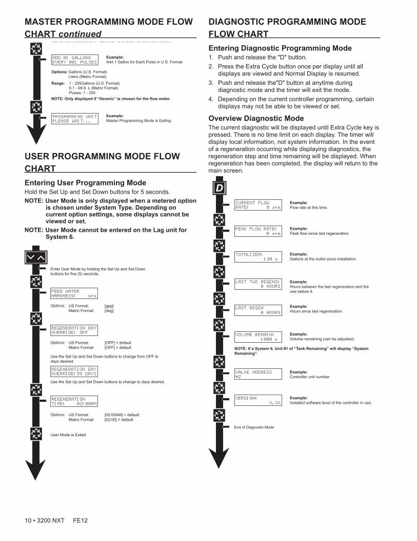
DIAGNOSTIC PROGRAMMING MODE FLOW CHARTEntering Diagnostic Programming Mode1. Push and release the "D" button.2. Press the Extra Cycle button once per display until all
displays are viewed and Normal Display is resumed.3. Push and release the"D" button at anytime during
diagnostic mode and the timer will exit the mode.4. Depending on the current controller programming, certain
displays may not be able to be viewed or set.
Overview Diagnostic ModeThe current diagnostic will be displayed until Extra Cycle key is pressed. There is no time limit on each display. The timer will display local information, not system information. In the event of a regeneration occurring while displaying diagnostics, the regeneration step and time remaining will be displayed. When regeneration has been completed, the display will return to the main screen.
CURRENT FLOW
RATE: 0 gpm
PEAK FLOW RATE:
0 gpm
TOTALIZER:
130 g
LAST TWO REGENS:
0 HOURS
LAST REGEN
0 HOURS
VOLUME REMAIN:
1000 g
VALVE ADDRESS
#2
VERSION:
X.XX
NOTE: If a System 6, Unit #1 of “Tank Remaining” will display “System Remaining”.
Example:Flow rate at this time.
Example:Peak flow since last regeneration.
Example:Gallons at the outlet since installation.
Example:Hours between the last regeneration and the one before it.
Example:Hours since last regeneration.
Example:Volume remaining (can be adjusted).
Example:Controller unit number.
Example:Installed software level of the controller in use.
USER PROGRAMMING MODE FLOW CHARTEntering User Programming ModeHold the Set Up and Set Down buttons for 5 seconds.NOTE: User Mode is only displayed when a metered option
is chosen under System Type. Depending on current option settings, some displays cannot be viewed or set.
NOTE: User Mode cannot be entered on the Lag unit for System 6.
FEED WATER
HARDNESS: gpg
REGENERATION DAY
OVERRIDE: OFF
REGENERATION DAY
OVERRIDE:99 DAYS
REGENERATION
TIME: 02:00AM
VALVE ADDRESS:
#2
Options: Valve Address #1 (First Control Valve) Valve Address #2 (Second Control Valve) (Default) Valve Address #3 (Third Control Valve) Valve Address #4 (Fourth Control Valve)
SYSTEM TYPE: 4
SINGLE UNIT
Options: System 4 (single unit) System 5 (2-4 units) Parallel Interlock System 6 (2-4 units) Parallel Series Regeneration System 7 (2 units) Alternating System 9 (2-4 units) Alternating System 14 (2-4 units) Demand Recall
Example:System Type 4, Single Unit
Example:Valve Address #2 (Second Control Valve) (Default)
Example:U.S. Gallons (Default)
SELECT LANGUAGE:
ENGLISH
Options: English Espanol Portugues Deutsch Francais
Example:English
VALVE TYPE:
2750
Options: 2750 (Default) 2850 2900 3150 3900 Stager - Notch Cam
Example:2750 (Default)
REGEN TYPE:
TIME CLK DELAYED
Options: Time Clock Delayed (System 4 Only) (Default) Meter Immediate (All System Types) Meter Delayed Fixed Reserve (Systems 4 & 6 Only)
Example:Time Clock Delayed (Default)
REGENERANT FLOW:
DOWNFLOW
Options: Downflow (Default) Up Flow UF Fill First
Example:Downflow (Default)
REMOTE SIGNAL
START: 00:06:00
Options: 00:06:00 (Default)Range: 1 second to 99 minutes (1 hour, 39 minutes)NOTE: This display will not be viewed in System 4
Example:00:06:00 (Default)(Hours:Minutes:Seconds)
NOTE: This screen will not display for System Type 4.
SYSTEM SIZE:
2 VALVES
Options: 2 Valves in the System (Default) 3 Valves in the System 4 Valves in the System
Example:2 Valves in the System (Default)
Range: 2 to 4 Valves in the SystemNOTE: This screen will not display for System Type 4.
DISPLAY FORMAT:
US-GALLONS
Options: U.S. - Gallons (Default) Eu Metric - Liters (Metric)
NOTE: In European Units - Liters (Metric) mode, the display will be in 24-hour time.
NOTE: In U.S. - Gallons mode, the display will be in 12-hour time.
UNIT CAPACITY:
00000000 GRAINS
Options: Grains (in U.S. Format) (Default) Grams (in Metric Format)
Example:Grains (Default)
NOTE: Use the Shift button to move to the left.
Range: 1 to 9,900,000 Grain Capacity in U.S. Format 1 to 198,000 grams CaCO3 Capacity in Metric Format
Example:00% (Default)
CAPACITY SAFETY
FACTOR: 00%
Range: 0 to 50%NOTE: Use the Shift button to move to the left.
FEED WATER
HARDNESS: 15 GPG
Range: 1 to 199 Grains/Gallon (U.S. Format) 20 to 1,999 miligrams CaCO3/L (Metric Format)
Example:15 GPG (U.S. Format) (Default)
NOTE: Use the Shift button to move to the left.NOTE: This screen will only display on the lead unit for System Types 6 & 7.For all other System Types, it will display for all units.
TRIP POINT 1:
000 gpm
NOTE: Display will not appear unless timer is programmed as valve position #1. Use the Shift button to change each decimal position.
REGENERATION DAY
OVERRIDE:OFF
Example:Off (Default)On (Default for time clock)
REGENERATION DAY
OVERRIDE:01 DAYS
Options: Off (Default for meter) or On
Example:1 Day
Range: 1 to 99 Days
REGENERATION
TIME: 02:00AM
Example:2:00 A.M. (Default)
Options: A.M. (U.S. Format) HR (Metric Format)NOTE: Regeneration time will not appear unless Regeneration Day Override is on.
CYCLE 1 00:00:00
BACK WASH
Example:Cycle 1 in Back Wash Mode
Options: Regeneration Cycle Step #1 Regeneration Cycle Step #2 Regeneration Cycle Step #3 Regeneration Cycle Step #4 Regeneration Cycle Step #5NOTE: Please refer to the “Regenerant Flow Default Cycle Steps & Times” in the Master Programming Mode section of the manual.NOTE: If Stager is chosen for Valve Type, the Regeneration Cycle Step description will not display.
AUXILIARY RELAY:
DISABLED
Example:Auxiliary Relay is Disabled
Options: Enabled Disabled (Default)
AUX RELAY OUTPUT
START 1 00:00:00
Example:Auxiliary Relay Output in Start 1 at 0 hours, 0 minutes, & 0 seconds
Range: 00:00:00 to 18:00:00NOTE: Only displayed if Auxiliary Relay is enabled in previous screen. Auxiliary Relay will only display if Chemical Pump is OFF for System Types 6 & 7.
AUX RELAY OUTPUT
END 1 00:00:00
Example:Auxiliary Relay Output in End 1 at 0 hours, 0 minutes, & 0 seconds
Range: 00:00:00 to 18:00:00
CHEMICAL PUMP:
DISABLED
Example:Chemical Pump is Disabled
Options: Enabled Disabled (Default)NOTE: This screen will only display on the lead unit for System Types 6 & 7. For all other System Types, it will display for all units.
CPO AUX RELAY
VOLUME: 000 g
Example:Energize Chemical Pump Relay Every 50 GallonsEnergize Chemical Pump Relay Every 200 L
Range: 1 to 999 gallons in U.S. Format 1 to 9.999 L in Metric FormatNOTE: Only displayed on units that physically have a meter (Lead always has a meter). Only shown if Auxiliary Relay is disabled on System Types 6 & 7.
CPO AUX RELAY
TIME: 00:00:00
Example:Each Time the Chemical Pump Relay is on, Run for 30 Seconds (00:00:30)
Range: 00:00:00 to 02:00:00
FLOW METER:
1.0 PADDLE
Example:1.0 Paddle Flow Meter
Options: 1.0 Paddle (Fleck) 1.0 Turbine (Fleck) 1.5 Paddle (Fleck) 1.5 Turbine (Fleck) 2.0 Paddle (Fleck) 3.0 Paddle (Fleck) Generic (Non-Fleck)NOTES: Default flow meter type is based on the valve type. This screen will only display on the lead unit for System Types 6 & 7. All other system types it will display for all units.
MAXIMUM FLOW
RATE: 0000 gpm
Example:Maximum Flow Rate of 0 gpm
Range: 20 - 2,000 gpm (U.S. Format) 20 - 200.0 L (Metric Format) NOTE: Only displayed if “Generic” is chosen for the flow meter.
Range: 1 - 255Gallons (U.S. Format) 0.1 - 09.9 L (Metric Format) Pulses: 1 - 255
Options: Gallons (U.S. Format) Liters (Metric Format)
ADD 01 GALLONS
EVERY 001 PULSES
Example:Add 1 Gallon for Each Pulse in U.S. Format
NOTE: Only displayed if “Generic” is chosen for the flow meter.
PROGRAMMING UNIT
PLEASE WAIT...
Example:Master Programming Mode is Exiting
NOTE: Display will not appear unless timer is programmed as valve position #1. Use the Shift button to move one space to the left.
TRIP DELAY 1:
30 SECONDS
NOTE: Display will not appear unless timer is programmed as valve position #1. System size must be 3 or 4 to appear. Use the Shift button to move one space to the left.
TRIP DELAY 2:
30 SECONDS
NOTE: Display will not appear unless timer is programmed as valve position #1. System size must be 3 or 4 to appear. Use the Shift button to move one space to the left.
TRIP POINT 2:
gpm
NOTE: Display will not appear unless timer is programmed as valve position #1. System size must be 4 to appear. Use the Shift button to move one space to the left.
TRIP POINT 3:
gpm
NOTE: Display will not appear unless timer is programmed as valve position #1. System size must be 4 to appear. Use the Shift button to move one space to the left.
TRIP DELAY 3:
30 SECONDS
10 • 3200 NXT FE12
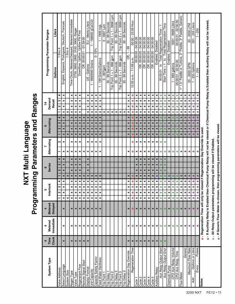
NX
T M
ult
i Lan
gu
age
P
rog
ram
min
g P
aram
eter
s an
d R
ang
es
Gal
lon
s L
iter
sV
alve
Add
ress
12
34
12
34
12
12
34
12
34
Sel
ect L
angu
age
xx
xx
xx
xx
xx
xx
xx
xx
xx
xx
xS
yste
m S
ize
xx
xx
xR
egen
Typ
ex
xx
xx
xx
xx
xx
xx
xx
xx
xx
xx
Val
ve T
ype
xx
xx
xx
xx
xx
xx
xx
xx
xx
xx
xR
egen
eran
t Flo
wx
xx
xx
xx
xx
xx
xx
xx
xx
xx
xx
Rem
ote
Sig
nal S
tart
xx
xx
xx
xx
xx
xx
xD
ispl
ay F
orm
atx
xx
xx
xx
xx
xx
xx
xx
xx
xx
xx
US
- G
allo
nsE
U -
Met
ric-L
iters
Uni
t Cap
acity
xx
xx
xx
xx
xx
xx
xx
xx
x1
- 99
0000
0 G
rain
s1
- 19
8000
gC
aCO
3C
apac
ity S
afet
y F
acto
rx
xx
xx
xx
xx
xx
xx
xx
xx
Fee
d W
ater
Har
dnes
sx
xx
xx
xx
xx
xx
xx
xx
xx
1 -
199
Gra
ins/
Gal
lons
1 -
1999
mgL
Trip
Poi
nt 1
x0
- 99
7gpm
0 -
3997
Lpm
Trip
Del
ay 1
x30
- 9
9 S
econ
ds30
- 9
9 S
econ
dsT
rip P
oint
2x
Trip
Poi
nt 1
+ 1
- 9
98 g
pmT
rip P
oint
1 +
1 -
399
8 Lp
mT
rip D
elay
2x
30 -
99
Sec
onds
30 -
99
Sec
onds
Trip
Poi
nt 3
xT
rip P
oint
2 +
1 -
999
gpm
Trip
Poi
nt 2
+ 1
- 3
999
Lpm
Trip
Del
ay 3
x30
- 9
9 S
econ
ds30
- 9
9 S
econ
dsR
egen
erat
ion
Day
Ove
rrid
ex
xx
xx
xx
xx
x
xx
xx
xx
xR
egen
erat
ion
Tim
ex
oo
oo
oo
oo
oo
oo
oo
oo
o12
:00
a.m
. - 1
1:59
p.m
.00
:00
- 23
:59
Hou
rC
ycle
1
xx
xx
xx
xx
xx
xx
xx
xx
xx
xx
xC
ycle
2x
xx
xx
xx
xx
xx
xx
xx
xx
xx
xx
Cyc
le 3
xx
xx
xx
xx
xx
xx
xx
xx
xx
xx
xC
ycle
4x
xx
xx
xx
xx
xx
xx
xx
xx
xx
xx
Cyc
le 5
xx
xx
xx
xx
xx
xx
xx
xx
xx
xx
xA
uxili
ary
Rel
ayx
xx
xx
xx
ux
xx
ux
xx
xx
xx
xx
Aux
Rel
ay O
utpu
t Sta
rtc
cc
cc
cc
cc
cc
cc
cc
cc
cc
cc
Aux
Rel
ay O
utpu
t End
c
cc
cc
cc
cc
cc
cc
cc
cc
cc
cc
Che
mic
al P
ump
xx
xx
xx
uu
xx
xx
xx
xx
CP
O A
ux R
elay
Vol
ume
cc
cc
cc
cc
cc
cc
cc
cc
1 -
999
gallo
ns00
01 -
999
9 Li
ters
CP
O A
ux R
elay
Tim
e
cc
cc
cc
cc
cc
cc
cc
cc
00:0
0:01
- 0
2:00
:00
00:0
0:01
- 0
2:00
:00
Flo
w M
eter
xx
xx
xx
xx
xx
xx
xx
xx
Gen
eric
xx
xx
xx
xx
xx
xx
xx
xx
Max
imum
Flo
w R
ate
aa
aa
aa
aa
aa
aa
aa
aa
20 -
200
0 G
PM
20 -
200
0 LP
MA
dd _
_ _
Gal
lons
or
Lite
rsa
aa
aa
aa
aa
aa
aa
aa
a1
- 25
5 G
allo
ns00
1 -
255
Lite
rsE
very
_ _
_ P
ulse
sa
aa
aa
aa
aa
aa
aa
aa
a1
- 25
51
- 25
5N
ote
so
-
u - c -
a -
Sys
tem
Typ
e
If G
ener
ic F
low
Met
er is
ch
ose
n, t
hen
pro
gra
mm
ing
par
amet
ers
will
be
view
ed.
Reg
ener
atio
n T
ime
will
on
ly b
e vi
ewed
if R
egen
erat
ion
Day
Ove
rrid
e is
use
d.
If A
uxi
liary
Rel
ay is
En
able
d t
hen
Ch
emic
al P
um
p R
elay
will
no
t b
e vi
ewed
or
if C
hem
ical
Pu
mp
Rel
ay is
En
able
d t
hen
Au
xilia
ry R
elay
will
no
t b
e vi
ewed
.
All
Rel
ay O
utp
ut
par
amet
ers
pro
gra
mm
ing
will
be
view
ed if
En
able
d.
00:0
0:01
to
T
otal
Reg
ener
atio
n T
ime
- 1
Sta
rt T
ime
+ 1
to
T
otal
Reg
ener
atio
n T
ime
Ena
bled
, Dis
able
d
Off,
1 -
99
00:
00:0
0 -
04:0
0:00
Off,
00:
00:0
0 -
04:0
0:00
1" 1
.5"
Pad
dle
or T
urbi
ne, 2
" P
addl
e, 3
" P
addl
e, G
ener
ic
Off,
00:
00:0
0 -
04:0
0:00
Off,
00:
00:0
0 -
04:0
0:00
Off,
00:
00:0
0 -
04:0
0:00
Ena
bled
, Dis
able
d
2750
, 285
0, 2
900,
315
0, 3
900,
Sta
ger
Dow
nflo
w, U
pflo
w, U
pflo
w F
ill F
irst
Off,
00:
00:0
1 -
01:3
9:00
0- 5
0%
6
S
erie
s7
A
lter
nat
ing
9
A
lter
nat
ing
Tim
e C
lock
, Met
ered
Del
ayed
, Met
ered
Imm
edia
te
Pro
gra
mm
ing
Par
amet
er R
ang
es4
Tim
e C
lock
4
Met
ered
Im
med
iate
4
Met
ered
D
elay
ed
5
In
terl
ock
14
D
eman
d
Rec
all
1 th
ru 4
Eng
lish,
Esp
anol
, Por
tugu
es, D
euts
ch, F
ranc
ais
1 th
ru 4
3200 NXT FE12 • 11

2750/2850/2900S UPPER & 2900S LOWER POWERHEAD ASSEMBLY
37 3531
41 39
32
197
6303632
40
20
38
33
22
1221
13
44
16
14
15
14 1716 46
25 16
261
42
23
46
2
114
3 5
67
10
19
32 28 29
186
11 439
8
32
24
61501-3200NXT-2_Page2_REVA
27
4547 48
51
49
50
12 • 3200 NXT FE12

Item No. QTY Part No. Description 1 ................1 ....... 18697-15 ...........Backplate, Hinged 2 ................1 ....... 60219-02 ...........Cover Assy, Environmental,
Black 3 ................1 ....... 60160-15 ...........Drive Cam Assy, Stf, Blue 4 ................1 ....... 10909 ................Pin, Link 5 ................2 ....... 14923 ................Screw, Pan Hd Mach, 4-40 X 1 6 ................5 ....... 10302 ................Insulator, Limit Switch 7 ................3 ....... 10218 ................Switch, Micro 8 ................2 ....... 10231 ................Screw, Slot Hex, 1/4 - 20 X 1/2 9 ................1 ....... 42579 ................Motor, Drive, 24V, 50/60 Hz 10 ..............1 ....... 12777 ................Cam, Shut-Off Valve 11 ..............2 ....... 10338 ................Pin, Roll, 3/32 X 7/8 12 ..............1 ....... 42469 ................Transformer, Us, 120V, 24V,
40Va ........ 41049 ................Transformer, Euro, 230V/24V
108Va ........ 41050 ................Transformer, Aust, 230V/24V,
108Va 13 ..............1 ....... 19691 ................Plug, .750 Dia, Recessed, Black 14 ..............2 ....... 19800 ................Plug, .140 Dia, White 15 ..............1 ....... 15806 ................Plug, Hole, Heyco #2693 16 ..............9 ....... 19801 ................Plug, .190 Dia, White, Heyco
#0307 17 ..............1 ....... 17967 ................Fitting Assy, Liquid Tight, Blk 18 ..............1 ....... 10896 ................Switch, Micro 19 ..............4 ....... 11805 ................Screw, Rd Hd, 4-40 X 5/8 Type 1 20 ..............1 ....... 40943 ................Wire Harness, Lower Drive, W/
Molded Strain Relief 21 ..............1 ....... 13547 ................Strain Relief, Flat Cord, Heyco
#30-1 22 ..............1 ....... 19121 ................Meter Cable Assy, 3200NT ........ 19121-08 ...........Meter Cable Assy, NT, 35” W/
Connector ........ 19121-09 ...........Meter Cable Assy, NT, 99.5” W/
Connector ........ 19121-10 ...........Meter Cable Assy, NT, 303.5” W/
Connector 23 ..............1 ....... 14202-01 ...........Screw, Hex Wsh Mach, 8-32 X
5/16 24 ..............1 ....... 40941 ................Wire Harness, Upper Drive 25 ..............1 ....... 17421 ................Plug, 1.20 Hole, Heyco #2733 26 ..............2 ....... 41581 ................Plug, Hole, .125 Dia, White 27 ..............1 ....... 60217-02 ...........Cover Assy, 2900, Lower, Black,
Environmental 28 ..............1 ....... 18626 ................Spacer, Indicator 29 ..............1 ....... 18746 ................Bearing, Connecting Rod 30 ..............2 ....... 11224 ................Screw, Hex Hd 5/16 - 18 X 5/8,
Ss 31 ..............1 ....... 10250 ................Ring, Retaining 32 ..............7 ....... 10872 ................Screw, Hex Wsh, 8-32 X 17/64 33 ..............1 ....... 18709 ................Backplate, Lower 34 ..............1 ....... 11381 ................Pin, Roll, 2900/3900 35 ..............1 ....... 14759 ................Link, Piston Rod 36 ..............1 ....... 14769 ................Bracket, Motor, 2900 37 ..............1 ....... 14775 ................Cam, Drive, 2900
38 ..............2 ....... 16346 ................Nut, Hex, Jam, 5/16-18, 18-8-Ss 39 ..............1 ....... 18725 ................Indicator, Service/Standby 40 ..............1 ....... 42580 ................Motor, Drive, 24V, 50/6 0Hz, Sp 41 ..............1 ....... 14813 ................Pin, Spring, Connecting Rod 42 ..............1 ....... 41102 ................Label, 3200Nt, Ground 43 ..............1 ....... 10269 ................Nut, Jam, 3/4 - 16 44 ..............1 ....... 10712 ................Fitting, Brine Valve 45 ..............1 ....... 61763 ................Kit, Can Communication Cable 46 ..............1 ....... 42466-11 ...........Timer Assy, Nxt, Right Hand 47 ........................ 60050-23 ...........Drive Assy, 2750, 2850, 2900S
Upper, STF, 24V 50/60 Hz ........ 60050-26 ...........Drive Assy, 2850S, STF, 24V
50/60 Hz 48 ........................ * ........................Powerhead Assy, 2750, 2850,
2900S Upper ........ * ........................Powerhead Assy, 2850S 49 ........................ * ........................Powerhead Assy, Lower 2900S 50 ........................ * ........................Powerhead Assy, Upper and
Lower 2900S 51 ........................ 60055-53 ...........Lower Drive Assy, 2900, 24/60*Call you distributor for a Part Number
NOTE: For all other service part numbers, see the Service Manual that accompanies the control valve.
Item No. QTY Part No. Description
2750/2850/2900S UPPER & 2900S LOWER POWERHEAD ASSEMBLY continued
3200 NXT FE12 • 13

3150/3900 UPPER & LOWER POWERHEAD ASSEMBLY
5
1
432
67
5
9
2726 11
46
7
812
6
47
4042
4
11
4515
25
35
16
432344
1817
20
2122
31
23
27 2611
10 8
13
1211 19 15
25 1716
24
34 9 14
2829
32
2838 30 50
2428
49
32 52
3748
2331
222120
18
33
52
61501-3200NXT-3_Pg2_REVA
39
39
51
41
3114
36
53
55
54
56
57
14 • 3200 NXT FE12
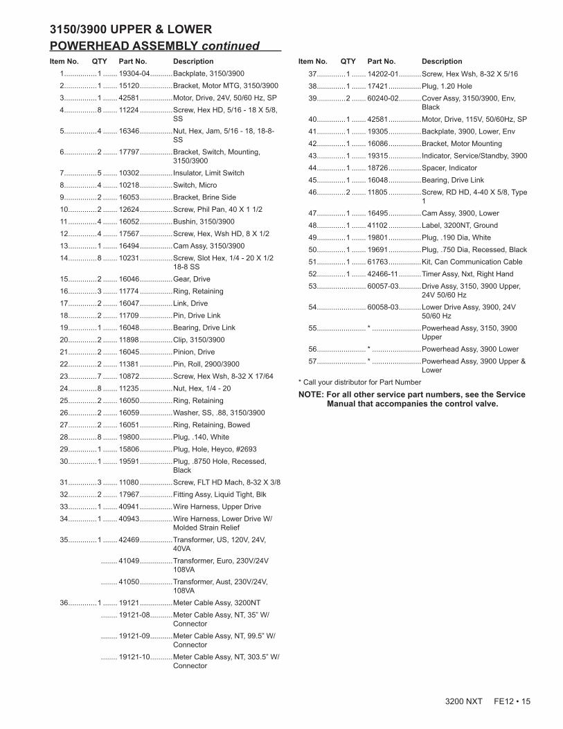
3150/3900 UPPER & LOWER POWERHEAD ASSEMBLY continuedItem No. QTY Part No. Description 1 ................1 ....... 19304-04 ...........Backplate, 3150/3900 2 ................1 ....... 15120 ................Bracket, Motor MTG, 3150/3900 3 ................1 ....... 42581 ................Motor, Drive, 24V, 50/60 Hz, SP 4 ................8 ....... 11224 ................Screw, Hex HD, 5/16 - 18 X 5/8,
SS 5 ................4 ....... 16346 ................Nut, Hex, Jam, 5/16 - 18, 18-8-
SS 6 ................2 ....... 17797 ................Bracket, Switch, Mounting,
3150/3900 7 ................5 ....... 10302 ................Insulator, Limit Switch 8 ................4 ....... 10218 ................Switch, Micro 9 ................2 ....... 16053 ................Bracket, Brine Side 10 ..............2 ....... 12624 ................Screw, Phil Pan, 40 X 1 1/2 11 ..............4 ....... 16052 ................Bushin, 3150/3900 12 ..............4 ....... 17567 ................Screw, Hex, Wsh HD, 8 X 1/2 13 ..............1 ....... 16494 ................Cam Assy, 3150/3900 14 ..............8 ....... 10231 ................Screw, Slot Hex, 1/4 - 20 X 1/2
18-8 SS 15 ..............2 ....... 16046 ................Gear, Drive 16 ..............3 ....... 11774 ................Ring, Retaining 17 ..............2 ....... 16047 ................Link, Drive 18 ..............2 ....... 11709 ................Pin, Drive Link 19 ..............1 ....... 16048 ................Bearing, Drive Link 20 ..............2 ....... 11898 ................Clip, 3150/3900 21 ..............2 ....... 16045 ................Pinion, Drive 22 ..............2 ....... 11381 ................Pin, Roll, 2900/3900 23 ..............7 ....... 10872 ................Screw, Hex Wsh, 8-32 X 17/64 24 ..............8 ....... 11235 ................Nut, Hex, 1/4 - 20 25 ..............2 ....... 16050 ................Ring, Retaining 26 ..............2 ....... 16059 ................Washer, SS, .88, 3150/3900 27 ..............2 ....... 16051 ................Ring, Retaining, Bowed 28 ..............8 ....... 19800 ................Plug, .140, White 29 ..............1 ....... 15806 ................Plug, Hole, Heyco, #2693 30 ..............1 ....... 19591 ................Plug, .8750 Hole, Recessed,
Black 31 ..............3 ....... 11080 ................Screw, FLT HD Mach, 8-32 X 3/8 32 ..............2 ....... 17967 ................Fitting Assy, Liquid Tight, Blk 33 ..............1 ....... 40941 ................Wire Harness, Upper Drive 34 ..............1 ....... 40943 ................Wire Harness, Lower Drive W/
Molded Strain Relief 35 ..............1 ....... 42469 ................Transformer, US, 120V, 24V,
40VA ........ 41049 ................Transformer, Euro, 230V/24V
108VA ........ 41050 ................Transformer, Aust, 230V/24V,
108VA 36 ..............1 ....... 19121 ................Meter Cable Assy, 3200NT ........ 19121-08 ...........Meter Cable Assy, NT, 35” W/
Connector ........ 19121-09 ...........Meter Cable Assy, NT, 99.5” W/
Connector ........ 19121-10 ...........Meter Cable Assy, NT, 303.5” W/
Connector
37 ..............1 ....... 14202-01 ...........Screw, Hex Wsh, 8-32 X 5/16 38 ..............1 ....... 17421 ................Plug, 1.20 Hole 39 ..............2 ....... 60240-02 ...........Cover Assy, 3150/3900, Env,
Black 40 ..............1 ....... 42581 ................Motor, Drive, 115V, 50/60Hz, SP 41 ..............1 ....... 19305 ................Backplate, 3900, Lower, Env 42 ..............1 ....... 16086 ................Bracket, Motor Mounting 43 ..............1 ....... 19315 ................Indicator, Service/Standby, 3900 44 ..............1 ....... 18726 ................Spacer, Indicator 45 ..............1 ....... 16048 ................Bearing, Drive Link 46 ..............2 ....... 11805 ................Screw, RD HD, 4-40 X 5/8, Type
1 47 ..............1 ....... 16495 ................Cam Assy, 3900, Lower 48 ..............1 ....... 41102 ................Label, 3200NT, Ground 49 ..............1 ....... 19801 ................Plug, .190 Dia, White 50 ..............1 ....... 19691 ................Plug, .750 Dia, Recessed, Black 51 ..............1 ....... 61763 ................Kit, Can Communication Cable 52 ..............1 ....... 42466-11 ...........Timer Assy, Nxt, Right Hand 53 ........................ 60057-03 ...........Drive Assy, 3150, 3900 Upper,
24V 50/60 Hz 54 ........................ 60058-03 ...........Lower Drive Assy, 3900, 24V
50/60 Hz 55 ........................ * ........................Powerhead Assy, 3150, 3900
Upper 56 ........................ * ........................Powerhead Assy, 3900 Lower 57 ........................ * ........................Powerhead Assy, 3900 Upper &
Lower* Call your distributor for Part Number
NOTE: For all other service part numbers, see the Service Manual that accompanies the control valve.
Item No. QTY Part No. Description
3200 NXT FE12 • 15
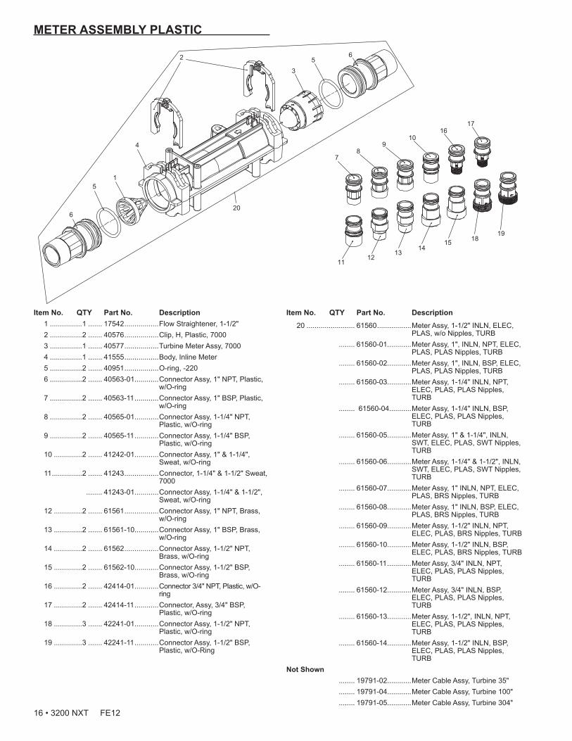
METER ASSEMBLY PLASTIC
65
3
4
2
15
6
78
910
1112
1314
15
1617
1819
20
Item No. QTY Part No. Description 1 ................1 ....... 17542 .................Flow Straightener, 1-1/2" 2 ................2 ....... 40576 .................Clip, H, Plastic, 7000 3 ................1 ....... 40577 .................Turbine Meter Assy, 7000 4 ................1 ....... 41555 .................Body, Inline Meter 5 ................2 ....... 40951 .................O-ring, -220 6 ................2 ....... 40563-01............Connector Assy, 1" NPT, Plastic,
w/O-ring 7 ................2 ....... 40563-11 ............Connector Assy, 1" BSP, Plastic,
w/O-ring 8 ................2 ....... 40565-01............Connector Assy, 1-1/4" NPT,
Plastic, w/O-ring 9 ................2 ....... 40565-11 ............Connector Assy, 1-1/4" BSP,
Plastic, w/O-ring 10 ..............2 ....... 41242-01............Connector Assy, 1" & 1-1/4",
Sweat, w/O-ring 11 ...............2 ....... 41243 .................Connector, 1-1/4" & 1-1/2" Sweat,
7000 ........ 41243-01............Connector Assy, 1-1/4" & 1-1/2",
Sweat, w/O-ring 12 ..............2 ....... 61561 .................Connector Assy, 1" NPT, Brass,
w/O-ring 13 ..............2 ....... 61561-10............Connector Assy, 1" BSP, Brass,
w/O-ring 14 ..............2 ....... 61562 .................Connector Assy, 1-1/2" NPT,
Brass, w/O-ring 15 ..............2 ....... 61562-10............Connector Assy, 1-1/2" BSP,
Brass, w/O-ring 16 ..............2 ....... 42414-01............Connector 3/4" NPT, Plastic, w/O-
ring 17 ..............2 ....... 42414-11 ............Connector, Assy, 3/4" BSP,
Plastic, w/O-ring 18 ..............3 ....... 42241-01............Connector Assy, 1-1/2" NPT,
Plastic, w/O-ring 19 ..............3 ....... 42241-11 ............Connector Assy, 1-1/2" BSP,
Plastic, w/O-Ring
20 ........................ 61560 .................Meter Assy, 1-1/2" INLN, ELEC, PLAS, w/o Nipples, TURB
........ 61560-01............Meter Assy, 1", INLN, NPT, ELEC, PLAS, PLAS Nipples, TURB
........ 61560-02............Meter Assy, 1", INLN, BSP, ELEC, PLAS, PLAS Nipples, TURB
........ 61560-03............Meter Assy, 1-1/4" INLN, NPT, ELEC, PLAS, PLAS Nipples, TURB
........ 61560-04...........Meter Assy, 1-1/4" INLN, BSP, ELEC, PLAS, PLAS Nipples, TURB
........ 61560-05............Meter Assy, 1" & 1-1/4", INLN, SWT, ELEC, PLAS, SWT Nipples, TURB
........ 61560-06............Meter Assy, 1-1/4" & 1-1/2", INLN, SWT, ELEC, PLAS, SWT Nipples, TURB
........ 61560-07............Meter Assy, 1" INLN, NPT, ELEC, PLAS, BRS Nipples, TURB
........ 61560-08............Meter Assy, 1" INLN, BSP, ELEC, PLAS, BRS Nipples, TURB
........ 61560-09............Meter Assy, 1-1/2" INLN, NPT, ELEC, PLAS, BRS Nipples, TURB
........ 61560-10............Meter Assy, 1-1/2" INLN, BSP, ELEC, PLAS, BRS Nipples, TURB
........ 61560-11 ............Meter Assy, 3/4" INLN, NPT, ELEC, PLAS, PLAS Nipples, TURB
........ 61560-12............Meter Assy, 3/4" INLN, BSP, ELEC, PLAS, PLAS Nipples, TURB
........ 61560-13............Meter Assy, 1-1/2", INLN, NPT, ELEC, PLAS, PLAS Nipples, TURB
........ 61560-14............Meter Assy, 1-1/2" INLN, BSP, ELEC, PLAS, PLAS Nipples, TURB
Not Shown ........ 19791-02............Meter Cable Assy, Turbine 35" ........ 19791-04............Meter Cable Assy, Turbine 100" ........ 19791-05............Meter Cable Assy, Turbine 304"
Item No. QTY Part No. Description
16 • 3200 NXT FE12
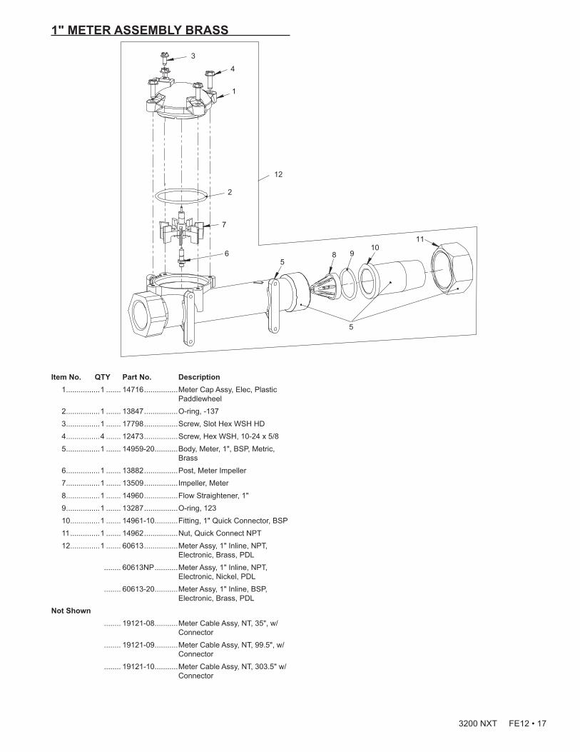
1" METER ASSEMBLY BRASS
Item No. QTY Part No. Description 1 ................1 ....... 14716 ................Meter Cap Assy, Elec, Plastic
Paddlewheel 2 ................1 ....... 13847 ................O-ring, -137 3 ................1 ....... 17798 ................Screw, Slot Hex WSH HD 4 ................4 ....... 12473 ................Screw, Hex WSH, 10-24 x 5/8 5 ................1 ....... 14959-20 ...........Body, Meter, 1", BSP, Metric,
Brass 6 ................1 ....... 13882 ................Post, Meter Impeller 7 ................1 ....... 13509 ................Impeller, Meter 8 ................1 ....... 14960 ................Flow Straightener, 1" 9 ................1 ....... 13287 ................O-ring, 123 10 ..............1 ....... 14961-10 ...........Fitting, 1" Quick Connector, BSP 11 ..............1 ....... 14962 ................Nut, Quick Connect NPT 12 ..............1 ....... 60613 ................Meter Assy, 1" Inline, NPT,
Electronic, Brass, PDL ........ 60613NP ...........Meter Assy, 1" Inline, NPT,
Electronic, Nickel, PDL ........ 60613-20 ...........Meter Assy, 1" Inline, BSP,
Electronic, Brass, PDLNot Shown ........ 19121-08 ...........Meter Cable Assy, NT, 35", w/
Connector ........ 19121-09 ...........Meter Cable Assy, NT, 99.5", w/
Connector ........ 19121-10 ...........Meter Cable Assy, NT, 303.5" w/
Connector
6
7
1
3
4
2
109
11
12
85
5
3200 NXT FE12 • 17
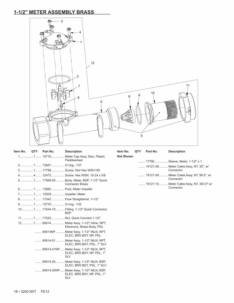
1-1/2" METER ASSEMBLY BRASS
Item No. QTY Part No. Description 1 ................1 ....... 14716 ................Meter Cap Assy, Elec, Plastic
Paddlewheel 2 ................1 ....... 13847 ................O-ring, -137 3 ................1 ....... 17798 ................Screw, Slot Hex WSH HD 4 ................4 ....... 12473 ................Screw, Hex WSH, 10-24 x 5/8 5 ................1 ....... 17569-20 ...........Body, Meter, BSP, 1-1/2" Quick
Connector Brass 6 ................1 ....... 13882 ................Post, Meter Impeller 7 ................1 ....... 13509 ................Impeller, Meter 8 ................1 ....... 17542 ................Flow Straightener, 1-1/2" 9 ................1 ....... 12733 ................O-ring, -132 10 ..............1 ....... 17544-10 ...........Fitting, 1-1/2" Quick Connector,
BSP 11 ..............1 ....... 17543 ................Nut, Quick Connect 1-1/2" 12 ..............1 ....... 60614 ................Meter Assy, 1-1/2" Inline, NPT,
Electronic, Brass Body, PDL ........ 60614NP ...........Meter Assy, 1-1/2" INLN, NPT,
ELEC, BRS BDY, NP, PDL ........ 60614-01 ...........Meter Assy, 1-1/2" INLN, NPT,
ELEC, BRS BDY, PDL, 1" SLV ........ 60614-01NP ......Meter Assy, 1-1/2" INLN, NPT,
ELEC, BRS BDY, NP, PDL, 1" SLV
........ 60614-20 ...........Meter Assy, 1-1/2" INLN, BSP, ELEC, BRS BDY, PDL, 1" SLV
........ 60614-20NP ......Meter Assy, 1-1/2" INLN, BSP, ELEC, BRS BDY, NP, PDL, 1" SLV
5
6
1
12
11
8 910
5
4
3
7
2
Not Shown ........ 17790 ................Sleeve, Meter, 1-1/2" x 1 ........ 19121-08 ...........Meter Cable Assy, NT, 35", w/
Connector ........ 19121-09 ...........Meter Cable Assy, NT, 99.5", w/
Connector ........ 19121-10 ...........Meter Cable Assy, NT, 303.5" w/
Connector
Item No. QTY Part No. Description
18 • 3200 NXT FE12

2" METER ASSEMBLY BRASS
Item No. QTY Part No. Description 1 ................1 ....... 14456 ................Body, Meter 2" 1 ....... 14456-20 ...........Body, Meter, 2", BSP,Metric 1 ....... 14456-20NP ......Body, Meter, 2", BSP,Metric, NP 2 ................1 ....... 15432 ................Shaft, Impeller, SS 3 ................1 ....... 15532 ................Seat, Impeller Shaft, Hex 4 ................1 ....... 15374-01 ...........Impeller, 2" Meter 5 ................1 ....... 15381 ................Plug, Impeller 2" Meter 6 ................1 ....... 17798 ................Screw, Slot Hex WSH HD 7 ................1 ....... 13847 ................O-ring, -137 8 .......................... 14716 ................Meter Cap Assy, ELEC, Plastic,
Paddlewheel 9 ................4 ....... 12473 ................Screw, Hex WSH, 10-24 x 5/8 4 ....... 21716 ................Screw, Hex Head, M5 x 16 10 ........................ 61439 ................Meter Sleeve w/O-ring, MACHD 11 ..............2 ....... 16080 ................O-ring, -032 12 ..............1 ....... 14680 ................Flow Straightener 13 ..............1 ....... 14568 ................Fitting, Nipple, 2" 1 ....... 14568-10 ...........Fitting, Nipple, 2", BSP, Brass 1 ....... 14568-10NP ......Fitting, Nipple, 2", BSP, Brass,
NP 14 ..............1 ....... 14679 ................O-ring, -227 15 ..............1 ....... 14569 ................Nut, Quick Connect 16 ........................ 60615 ................Meter Assy, 2" INLN, NPT,
ELEC, BRS, PDL, 1.5" SLV ........ 60615NP ...........Meter Assy, 2" INLN, NPT,
ELEC, NP, PDL, 1.5" SLV ........ 60615-20 ...........Meter Assy, 2" INLN, BSP/MET,
ELEC, BRS, PDL, 1.5" SLV ........ 60615-20NP ......Meter Assy, 2" INLN, BSP/MET,
ELEC, NP, PDL, 1.5" SLV
1
7
15
16
13
3
2
5
4
6
8
11
12
9
10
14
12 16
13
14
1
3
2
5
4
6
8
9
7 17
17 ........................ 60616 ................Meter Assy, 2" INLN, NPT, ELEC, BRS, PDL
........ 60616NP ...........Meter Assy, 2" INLN, NPT, ELEC, NP, PDL
........ 60616-20 ...........Meter Assy, 2" INLN, BSP/MET, ELEC, BRS, PDL
........ 60616-20NP ......Meter Assy, 2" INLN, BSP/MET, ELEC, NP, PDL
Not Shown ........ 19121-08 ...........Meter Cable Assy, NT, 35", w/
Connector ........ 19121-09 ...........Meter Cable Assy, NT, 99.5", w/
Connector ........ 19121-10 ...........Meter Cable Assy, NT, 303.5" w/
Connector
Item No. QTY Part No. Description
3200 NXT FE12 • 19
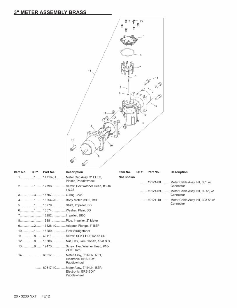
3" METER ASSEMBLY BRASS
Item No. QTY Part No. Description 1 ................1 ....... 14716-01 ...........Meter Cap Assy, 3" ELEC,
Plastic, Paddlewheel 2 ................1 ....... 17798 ................Screw, Hex Washer Head, #8-16
x 0.38 3 ................3 ....... 15707 ................O-ring, -236 4 ................1 ....... 16254-20 ...........Body Meter, 3900, BSP 5 ................1 ....... 16279 ................Shaft, Impeller, SS 6 ................1 ....... 16574 ................Washer, Plain, SS 7 ................1 ....... 16252 ................Impeller, 3900 8 ................1 ....... 15381 ................Plug, Impeller, 2" Meter 9 ................2 ....... 16328-10 ...........Adapter, Flange, 3" BSP 10 ..............1 ....... 16280 ................Flow Straightener 11 ..............8 ....... 40118 ................Screw, SCKT HD, 1/2-13 UN 12 ..............8 ....... 16386 ................Nut, Hex, Jam, 1/2-13, 18-8 S.S. 13 ..............6 ....... 12473 ................Screw, Hex Washer Head, #10-
24 x 0.625 14 ........................ 60617 ................Meter Assy, 3" INLN, NPT,
Electronic, BRS BDY, Paddlewheel
........ 60617-10 ...........Meter Assy, 3" INLN, BSP, Electronic, BRS BDY, Paddlewheel
132
1
7
118
9
5
6
4
10
12
3
3
3
9
11
14
Not Shown ........ 19121-08 ...........Meter Cable Assy, NT, 35", w/
Connector ........ 19121-09 ...........Meter Cable Assy, NT, 99.5", w/
Connector ........ 19121-10 ...........Meter Cable Assy, NT, 303.5" w/
Connector
Item No. QTY Part No. Description
20 • 3200 NXT FE12
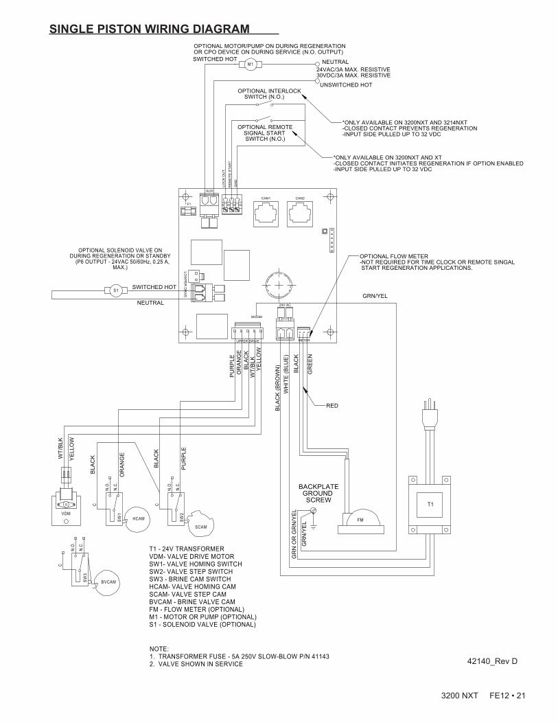
SINGLE PISTON WIRING DIAGRAM
BVCAM
HCAM
SCAM
M1
C
N.O
.
N.C
.SW
1VDMFM
C
N.O
.
N.C
.SW
3
C
N.O
.
N.C
.SW
2
S1
T1 - 24V TRANSFORMERVDM- VALVE DRIVE MOTORSW1- VALVE HOMING SWITCHSW2- VALVE STEP SWITCHSW3 - BRINE CAM SWITCHHCAM- VALVE HOMING CAMSCAM- VALVE STEP CAMBVCAM - BRINE VALVE CAMFM - FLOW METER (OPTIONAL)M1 - MOTOR OR PUMP (OPTIONAL)S1 - SOLENOID VALVE (OPTIONAL)
NOTE: 1. TRANSFORMER FUSE - 5A 250V SLOW-BLOW P/N 411432. VALVE SHOWN IN SERVICE
T1
WT/
BLK
YE
LLO
W
BLA
CK
OR
AN
GE
BLA
CK
PU
RP
LE
PU
RP
LEO
RA
NG
EB
LAC
K
YE
LLO
WW
T/B
LK
BLA
CK
(BR
OW
N)
WH
ITE
(BLU
E)
BLA
CK
GR
EE
N
RED
GR
N O
R G
RN
/YE
L
GR
N/Y
EL
BACKPLATEGROUND SCREW
GRN/YELSWITCHED HOT
NEUTRAL
OPTIONAL SOLENOID VALVE ON DURING REGENERATION OR STANDBY (P6 OUTPUT - 24VAC 50/60Hz, 0.25 A,
MAX.)
OPTIONAL INTERLOCK SWITCH (N.O.)
UNSWITCHED HOT
24VAC/3A MAX. RESISTIVE30VDC/3A MAX. RESISTIVE
NEUTRALSWITCHED HOT
OPTIONAL MOTOR/PUMP ON DURING REGENERATION OR CPO DEVICE ON DURING SERVICE (N.O. OUTPUT)
OPTIONAL REMOTESIGNAL START SWITCH (N.O.)
*ONLY AVAILABLE ON 3200NXT AND 3214NXT-CLOSED CONTACT PREVENTS REGENERATION-INPUT SIDE PULLED UP TO 32 VDC
*ONLY AVAILABLE ON 3200NXT AND XT-CLOSED CONTACT INITIATES REGENERATION IF OPTION ENABLED-INPUT SIDE PULLED UP TO 32 VDC
CAN1 CAN2
METER
24V AC
UPPER DRIVE
LOW
PE
RD
RIV
E
LOC
K O
UT
RE
MO
TE S
TAR
T
GN
D
AUX
F1
OPTIONAL FLOW METER-NOT REQUIRED FOR TIME CLOCK OR REMOTE SINGAL START REGENERATION APPLICATIONS.
42140_Rev D
3200 NXT FE12 • 21

DUAL PISTON WIRING DIAGRAM
BVCAM
SCAM
M1
VDM FM
C
N.O
.
N.C
.SW
3
C
N.O
.
N.C
.SW
2
HCAM
C
N.O
.
N.C
.SW
1
T1 - 24V TRANSFORMERVDM- VALVE DRIVE MOTORSW1- VALVE HOMING SWITCHSW2- VALVE STEP SWITCHSW3 - BRINE CAM SWITCHHCAM- VALVE HOMING CAMSCAM- VALVE STEP CAMBVCAM - BRINE VALVE CAMFM - FLOW METER (OPTIONAL)M1 - MOTOR OR PUMP (OPTIONAL)S1 - SOLENOID VALVE (OPTIONAL)
NOTE: 1. TRANSFORMER FUSE - 5A 250V SLOW-BLOW P/N 411432. VALVE SHOWN IN SERVICE
PUR
PLE
BLAC
K
YELL
OW
BLAC
K (B
RO
WN
)
GR
N/Y
EL
WT/
BLK
UNSWITCHED HOT
BLAC
K
WT/
BLK
OR
ANG
E
WH
ITE
(BLU
E)
NEUTRALYE
LLO
W
PUR
PLE
GR
N O
R G
RN
/YEL
T1
BACKPLATE GROUND SCREW
GRN/YEL
OPTIONAL INTERLOCK SWITCH (N.O.)
24VAC/3A MAX. RESISTIVE30VDC/3A MAX. RESISTIVE
SWITCHED HOT
BLAC
K
OR
ANG
E
RED
WH
ITE
BLAC
K
C
N.O
.
N.C
.SW
4G
REE
N
LDCAMLDM
RED
BLACKWHITE
GREEN
LOWER DRIVE
UPPER DRIVE
BLAC
K
RED
GR
EEN
OPTIONAL MOTOR/PUMP ON DURING REGENERATION OR CPO DEVICE ON DURING SERVICE(N.O.OUTPUT)
*ONLY AVAILABLE ON 3200NXT AND 3214NXT-CLOSED CONTACT PREVENTS REGENERATION-INPUT SIDE PULLED UP TO 32 VDCOPTIONAL REMOTE
SIGNAL START SWITCH (N.O.)
*ONLY AVAILABLE ON 3200NXT AND XT-CLOSED CONTACT INITIATES REGENERATION IF OPTION ENABLED-INPUT SIDE PULLED UP TO 32 VDC
CAN2CAN1
RE
MO
TE S
TAR
T
GN
D
LOC
K O
UT
AUX
LOW
PE
RD
RIV
E
UPPER DRIVE
24V AC
METER
F1
OPTIONAL FLOW METER- NOT REQUIRED FOR TIME CLOCK OR REMOTE SIGNAL START REGENERATION APPLICATIONS
42140_Rev C
22 • 3200 NXT FE12

REMOTE TIMER WIRING DIAGRAM
1.25MIN
31.8
GREEN/YELLOW
BACKPLATE GROUND SCREW
WHITE
GREEN/BLACK STRIPE
RED
��
GR
N O
R G
RN
/YE
LB
LAC
K (B
LUE
)
GR
N/Y
EL
WH
ITE
(BR
OW
N)
BLUE
ORANGE
ORANGE/BLACK STRIPE
BLACK
BLACK/WHITE STRIPE
RED/WHITE STRIPE
GREEN/WHITE STRIPE
WHITE/BLACK STRIPE
RED/BLACK STRIPE
BLUE/BLACK STRIPEBLUE/WHITE STRIPE
GREEN3
19
13
14
28
17
15
12
11
1
18
1645
CONNECTORFRONT VIEW
BELDEN 9458OR EQUIVALENT
CABLE ENTRY SEALAMP P/N 54012-1
CONNECTOR PLUGAMP #211770-2WITH AMP SOCKET #66104-8
CAN2CAN1
AUX
LOW
PE
RD
RIV
EUPPER DRIVE
24V AC
METER
F1
3200 NXT FE12 • 23
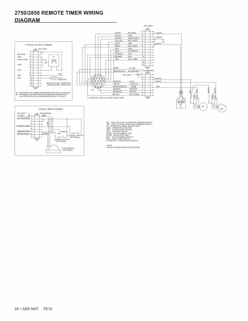
2750/2850 REMOTE TIMER WIRING DIAGRAM
NOTE:VALVE SHOWN IN SERVICE POSITION.
TB1 - HIGH VOLTAGE 14 POSITION TERMINAL BLOCKTB2 - LOW VOLTAGE 9 POSITION TERMINAL BLOCKIC1 - INTERLOCK CABLE RECEPTACLEUDM - UPPER DRIVE MOTORLDM - LOWER DRIVE MOTORAUX - AUXILARY RELAYHCAM - VALVE HOMING CAMSCAM - VALVE STEP CAMSW1 - VALVE HOMING SWITCHSW2 - VALVE STEP SWITCHLD SWITCH - LOWER DRIVE SWITCH
TYPICAL INPUT WIRING
LOCKOUT SWITCH
SENSOR SWITCH
LOCKOUT INPUT
RED
GREENMETER INPUTSENSOR INPUT
(OPTIONAL)
(OPTIONAL)
TB2-ORANGE
SHIELD
(OPTIONAL)
2
5
1
4
87
DC GROUND+5 VDC
FLOW METER
3
6
9
P/N 19781
����
�
����
����
�
����
����
���
�
����
����
���
���
�� �� �� ��
�� �� ��
��������
� � � �
� � �
BLK
TAN
PINK
BLUE
HOME
P/N 19781
NOT USED
UDM
LINE
RED
BLACK
BLACK
IC1
REDGREY
METER
STEP
AUX
LDM
WHITE
GREEN
WHITE
RE
D
BLA
CK
+5 VDC
#BLACK NOT USED 9
#WHITE/BLACK 6
3
DC GROUND#RED/BLACK
11
8
5
2KCALB
#ORANGE 8
#GREEN SENSOR 7
2
#WHITE 4
1
TB2-ORANGE
13
01NWORB
12
AUX 9EGNARO
7
4WOLLEY
NOT USED 6
EARTH GND 3NEERG
WHITE NEUTRAL 11
TB1-GREY
WH
ITE
#BLUE LOCKOUT 5
#RED
# - DENOTES LOW VOLTAGE CABLE WIRE
NOT USED
LD SWITCH
��
1NEUTRAL
7LDM
13
TYPICAL OUTPUT WIRING
1
3EARTH GND
6
4
AUX 9
12
10AUX
S1 - SOLENOID ON DURING REGENERATION 24VAC,0.25A MAXM1 -OPTIONAL MOTOR/PUMP ON DURING REGENERATION OR CPO DEVICE ON DURING SERVICE(N.O. OUTPUT)
2
5UDM
8
11
TB1-GREY
LINE S1
HOT
NEUTRAL
250VAC/3A MAX. RESISTIVE 30VDC/3A MAX. RESISTIVE
24 • 3200 NXT FE12

2900 REMOTE TIMER WIRING DIAGRAM
NOTE:VALVE SHOWN IN SERVICE POSITION.
TB1 - HIGH VOLTAGE 14 POSITION TERMINAL BLOCKTB2 - LOW VOLTAGE 9 POSITION TERMINAL BLOCKIC1 - INTERLOCK CABLE RECEPTACLEUDM - UPPER DRIVE MOTORLDM - LOWER DRIVE MOTORAUX - AUXILARY RELAYHCAM - VALVE HOMING CAMSCAM - VALVE STEP CAMSW1 - VALVE HOMING SWITCHSW2 - VALVE STEP SWITCHSW3 - LOWER DRIVE SWITCH(INSIDE)SW4 - LOWER DRIVE SENSE SWITCH(OUTSIDE)LD SWITCH - LOWER DRIVE SWITCHLDCAM - LOWER DRIVE CAM
��
1NEUTRAL
7LDM
13
TYPICAL OUTPUT WIRING
1
3EARTH GND
6
4
AUX 9
12
10AUX
S1 - SOLENOID ON DURING REGENERATION 24VAC,0.25A MAXM1 -OPTIONAL MOTOR/PUMP ON DURING REGENERATION OR CPO DEVICE ON DURING SERVICE(N.O. OUTPUT)
2
5UDM
8
11
TB1-GREY
LINE
HOT
NEUTRAL
250VAC/3A MAX. RESISTIVE 30VDC/3A MAX. RESISTIVE
����
����
�
����
����
���
�
����
����
���
���
�� �� �� ��
�� �� ��
��������
� � � �
� � �
���
�����
�
����
����
���
BLK
TAN
PINK
BLUE
HOME
P/N 19781
NOT USED
UDM
LINE
RED
GREEN
BLACK
IC1
REDGREY
METER
STEP
AUX
LDM
WHITE
GREEN
WHITE
RE
D
BLA
CK
+5 VDC
#BLACK NOT USED 9
#WHITE/BLACK 6
3
DC GROUND#RED/BLACK
11
8
5
2KCALB
#ORANGE 8
#GREEN SENSOR 7
2
#WHITE 4
1
TB2-ORANGE
13
01NWORB
12
AUX 9EGNARO
7
4WOLLEY
NOT USED 6
EARTH GND 3NEERG
WHITE NEUTRAL 11
TB1-GREY
WH
ITE
#BLUE LOCKOUT 5
#RED
# - DENOTES LOW VOLTAGE CABLE WIRE
NOT USED
LD SWITCH
WHITE
BLACK
UPPER DRIVE
BLA
CK
WH
ITE
RE
D
GR
EE
N
LOWER DRIVE
BLACKRED
����
�
P/N 19781
9
6
3
FLOW METER
+5 VDCDC GROUND
78
4
1
5
2
(OPTIONAL)
SHIELD
TB2-ORANGE
(OPTIONAL)
(OPTIONAL)
SENSOR INPUTMETER INPUT GREEN
RED
LOCKOUT INPUT
SENSOR SWITCH
LOCKOUT SWITCH
TYPICAL INPUT WIRING
3200 NXT FE12 • 25
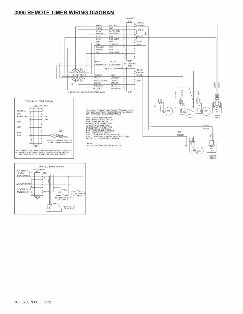
3900 REMOTE TIMER WIRING DIAGRAM
NOTE:VALVE SHOWN IN SERVICE POSITION.
TB1 - HIGH VOLTAGE 14 POSITION TERMINAL BLOCKTB2 - LOW VOLTAGE 9 POSITION TERMINAL BLOCKIC1 - INTERLOCK CABLE RECEPTACLE
UDM - UPPER DRIVE MOTORLDM - LOWER DRIVE MOTORAUX - AUXILARY RELAYHCAM - VALVE HOMING CAMSCAM - VALVE STEP CAMLDCAM - LOWER DRIVE CAMBVCAM - BRINE VALVE CAMSW1 - VALVE HOMING SWITCHSW2 - VALVE STEP SWITCHSW3 - LOWER DRIVE SWITCH(INSIDE)SW4 - LOWER DRIVE SENSE SWITCH(OUTSIDE)LD SWITCH - LOWER DRIVE SWITCH
��
1NEUTRAL
7LDM
13
TYPICAL OUTPUT WIRING
1
3EARTH GND
6
4
AUX 9
12
10AUX
S1 - SOLENOID ON DURING REGENERATION 24VAC,0.25A MAXM1 -OPTIONAL MOTOR/PUMP ON DURING REGENERATION OR CPO DEVICE ON DURING SERVICE(N.O. OUTPUT)
2
5UDM
8
11
TB1-GREY
LINE
HOT
NEUTRAL
250VAC/3A MAX. RESISTIVE 30VDC/3A MAX. RESISTIVE
����
�
P/N 19781
9
6
3
FLOW METER
+5 VDCDC GROUND
78
4
1
5
2
(OPTIONAL)
SHIELD
TB2-ORANGE
(OPTIONAL)
(OPTIONAL)
SENSOR INPUTMETER INPUT GREEN
RED
LOCKOUT INPUT
SENSOR SWITCH
LOCKOUT SWITCH
TYPICAL INPUT WIRING
�� �� �� ��
�� �� ��
��������
� � � �
� � �
�
����
����
���
�
����
����
���
�
����
����
���
�������
����
�����
�
����
����
���
�����
���
TAN
PINK
BLUE
HOME
P/N 19781
NOT USED
UDM
LINE
RED
BLACK
IC1
REDGREY
METER
STEP
AUX
LDM
WHITE
GREEN
WHITE
+5 VDC
#BLACK NOT USED 9
#WHITE/BLACK 6
3
DC GROUND#RED/BLACK
11
8
5
2KCALB
#ORANGE 8
#GREEN SENSOR 7
2
#WHITE 4
1
TB2-ORANGE
13
01NWORB
12
AUX 9EGNARO
7
4WOLLEY
NOT USED 6
EARTH GND 3NEERG
WHITE NEUTRAL 11
TB1-GREY
#BLUE LOCKOUT 5
#RED
# - DENOTES LOW VOLTAGE CABLE WIRE
NOT USED
BLACK
WH
ITE
BLA
CK
RE
D
LD SWITCH
WH
ITE
BLA
CK
LOWER DRIVE
WHITE
UPPER DRIVE
BLACKRED
GREEN
BLACK
WHITE
RED
GREEN
26 • 3200 NXT FE12

3150 REMOTE METER WIRING DIAGRAM
NOTE:VALVE SHOWN IN SERVICE POSITION.
TB1 - HIGH VOLTAGE 14 POSITION TERMINAL BLOCKTB2 - LOW VOLTAGE 9 POSITION TERMINAL BLOCKIC1 - INTERLOCK CABLE RECEPTACLEUDM - UPPER DRIVE MOTORLDM - LOWER DRIVE MOTORAUX - AUXILARY RELAYHCAM - VALVE HOMING CAMSCAM - VALVE STEP CAMBVCAM - BRINE VALVE CAMSW1 - VALVE HOMING SWITCHSW2 - VALVE STEP SWITCH
��
1NEUTRAL
7LDM
13
TYPICAL OUTPUT WIRING
1
3EARTH GND
6
4
AUX 9
12
10AUX
S1 - SOLENOID ON DURING REGENERATION 24VAC,0.25A MAXM1 -OPTIONAL MOTOR/PUMP ON DURING REGENERATION OR CPO DEVICE ON DURING SERVICE(N.O. OUTPUT)
2
5UDM
8
11
TB1-GREY
LINE S1
HOT
NEUTRAL
250VAC/3A MAX. RESISTIVE 30VDC/3A MAX. RESISTIVE
����
�
P/N 19781
9
6
3
FLOW METER
+5 VDCDC GROUND
78
4
1
5
2
(OPTIONAL)
SHIELD
TB2-ORANGE
(OPTIONAL)
(OPTIONAL)
SENSOR INPUTMETER INPUT GREEN
RED
LOCKOUT INPUT
SENSOR SWITCH
LOCKOUT SWITCH
TYPICAL INPUT WIRING
�� �� �� ��
�� �� ��
��������
� � � �
� � �
�
����
����
���
�
����
����
���
�
����
����
���
�������
����
�����
TAN
PINK
BLUE
HOME
P/N 19781
NOT USED
UDM
LINE
RED
BLACK
IC1
REDGREY
METER
STEP
AUX
LDM
WHITE
GREEN
WHITE
+5 VDC
#BLACK NOT USED 9
#WHITE/BLACK 6
3
DC GROUND#RED/BLACK
11
8
5
2KCALB
#ORANGE 8
#GREEN SENSOR 7
2
#WHITE 4
1
TB2-ORANGE
13
01NWORB
12
AUX 9EGNARO
7
4WOLLEY
NOT USED 6
EARTH GND 3NEERG
WHITE NEUTRAL 11
TB1-GREY
#BLUE LOCKOUT 5
#RED
# - DENOTES LOW VOLTAGE CABLE WIRE
NOT USED
BLACK
WH
ITE
BLA
CK
RE
D
NOT USED
WH
ITE
BLA
CK
3200 NXT FE12 • 27
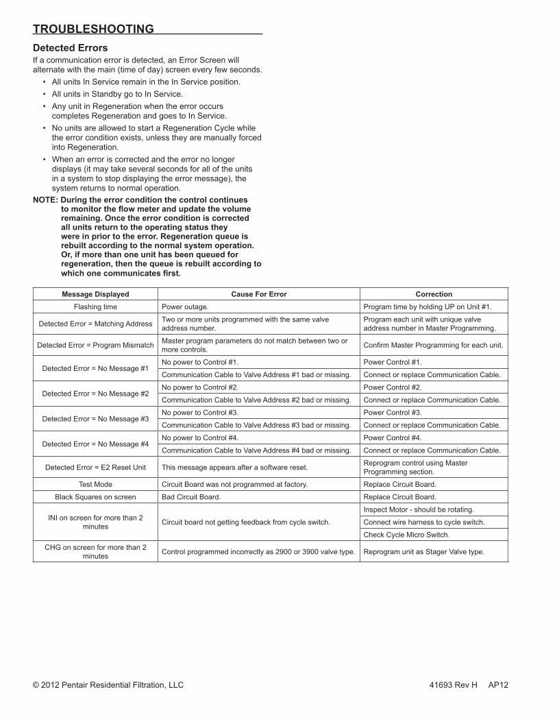
TROUBLESHOOTINGDetected ErrorsIf a communication error is detected, an Error Screen will alternate with the main (time of day) screen every few seconds.
• All units In Service remain in the In Service position.• All units in Standby go to In Service.• Any unit in Regeneration when the error occurs
completes Regeneration and goes to In Service.• No units are allowed to start a Regeneration Cycle while
the error condition exists, unless they are manually forced into Regeneration.
• When an error is corrected and the error no longer displays (it may take several seconds for all of the units in a system to stop displaying the error message), the system returns to normal operation.
NOTE: During the error condition the control continues to monitor the flow meter and update the volume remaining. Once the error condition is corrected all units return to the operating status they were in prior to the error. Regeneration queue is rebuilt according to the normal system operation. Or, if more than one unit has been queued for regeneration, then the queue is rebuilt according to which one communicates first.
Message Displayed Cause For Error CorrectionFlashing time Power outage. Program time by holding UP on Unit #1.
Detected Error = Matching Address Two or more units programmed with the same valve address number.
Program each unit with unique valve address number in Master Programming.
Detected Error = Program Mismatch Master program parameters do not match between two or more controls. Confirm Master Programming for each unit.
Detected Error = No Message #1No power to Control #1. Power Control #1.
Communication Cable to Valve Address #1 bad or missing. Connect or replace Communication Cable.
Detected Error = No Message #2No power to Control #2. Power Control #2.
Communication Cable to Valve Address #2 bad or missing. Connect or replace Communication Cable.
Detected Error = No Message #3No power to Control #3. Power Control #3.
Communication Cable to Valve Address #3 bad or missing. Connect or replace Communication Cable.
Detected Error = No Message #4No power to Control #4. Power Control #4.
Communication Cable to Valve Address #4 bad or missing. Connect or replace Communication Cable.
Detected Error = E2 Reset Unit This message appears after a software reset. Reprogram control using Master Programming section.
Test Mode Circuit Board was not programmed at factory. Replace Circuit Board.
Black Squares on screen Bad Circuit Board. Replace Circuit Board.
INI on screen for more than 2 minutes Circuit board not getting feedback from cycle switch.
Inspect Motor - should be rotating.
Connect wire harness to cycle switch.
Check Cycle Micro Switch.
CHG on screen for more than 2 minutes Control programmed incorrectly as 2900 or 3900 valve type. Reprogram unit as Stager Valve type.
© 2012 Pentair Residential Filtration, LLC 41693 Rev H AP12