32€¦ · · 2017-08-04lect-32 s t 2 4 5. 3 a 7 ideal turbojet cycle (without afterburning) on a...
TRANSCRIPT

1
32

In this lecture ...• Ideal gas turbine cycles• Thrust and efficiency• The thrust equation• Other engine performance parameters• Ideal cycle for jet engines
– Turbojet engine – Turbojet engine with afterburning
Prof. Bhaskar Roy, Prof. A M Pradeep, Department of Aerospace, IIT Bombay2
Lect-32

Gas turbine cycles• Gas turbine engines operate on Brayton
cycles.• Ideal Brayton cycle is a closed cycle,
whereas gas turbines operate in the open cycle mode.
• Ideal cycle assumes that there are no irreversibilities in the processes, air behaves like an ideal gas with constant specific heats, and that there are no frictional losses.
Prof. Bhaskar Roy, Prof. A M Pradeep, Department of Aerospace, IIT Bombay3
Lect-32

Thrust and efficiency
• We will now derive expressions for thrust and efficiency of air-breathing engines from the momentum and energy equations.
• We shall consider a generalized thrust producing device with a single inlet and single exhaust.
• We assume that the thrust and conditions at all points within the control volume do not change with time.
Prof. Bhaskar Roy, Prof. A M Pradeep, Department of Aerospace, IIT Bombay4
Lect-32
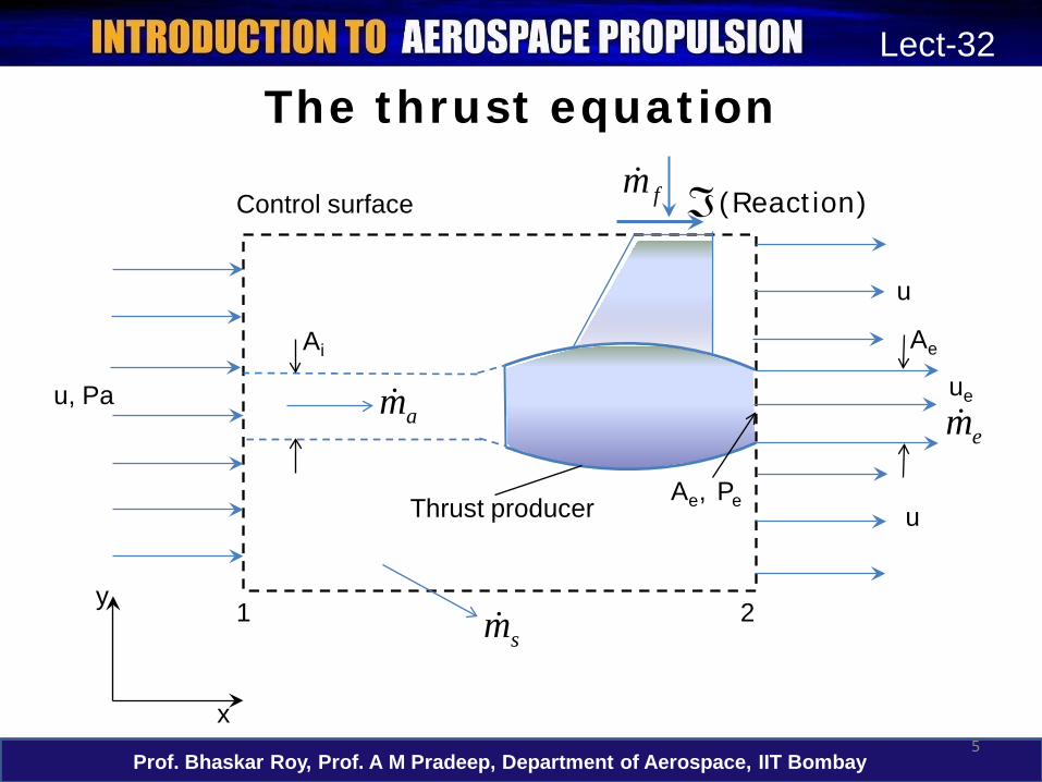
The thrust equation
Prof. Bhaskar Roy, Prof. A M Pradeep, Department of Aerospace, IIT Bombay5
Lect-32
(Reaction)Control surface
Thrust producer
u, Pa
u
u
Ai Ae
ue
21
x
y
Ae, Pe
amem
sm
fm ℑ

The thrust equation• The reaction to the thrust, , is transmitted
to the support. The engine thrust is thus the vector summation of all forces on the internal and external surfaces of the engine.
• Therefore,
• Considering the components of force and the momentum flux in the x-direction only,
Prof. Bhaskar Roy, Prof. A M Pradeep, Department of Aerospace, IIT Bombay6
Lect-32
∫∑ =CS
dAnuuF ).( ρ
∫∑ =CS
xx dAnuuF ).( ρ
ℑ

The thrust equation• The pressure and velocity can be
assumed to be constant over the entire control surface, except over the exhaust area, Ae.
• The net pressure force acting on this control volume is (Pa–Pe)Ae.
• The only other force acting on the control volume is the reaction to the thrust, .
• Adding up the forces in the x-direction,
Prof. Bhaskar Roy, Prof. A M Pradeep, Department of Aerospace, IIT Bombay7
Lect-32
ℑ+−=∑ eeax APPF )(
ℑ

The thrust equation• The mass flow that enters the capture area,
Ai, is • Similarly, the mass flow crossing the exhaust
area Ae, is, • Also,
Or,• Continuity equation for the CV gives,
Prof. Bhaskar Roy, Prof. A M Pradeep, Department of Aerospace, IIT Bombay8
Lect-32
ia uAm ρ=
eeee Aum ρ=
fie mmm +=ieeef uAAum ρρ −=
)( is,Which
g,Rearrangin
0)(
ies
eeeefs
fseeee
AAumAuuAmm
uAmmAAuAu
−=
−+=
=−−+−+
ρ
ρρ
ρρρ

The thrust equation
Prof. Bhaskar Roy, Prof. A M Pradeep, Department of Aerospace, IIT Bombay9
Lect-32
(Reaction)Control surface
Thrust producer
u, Pa
u
u
Ai Ae
ue
21
x
y
Ae, Pe
amem
sm
fm ℑ
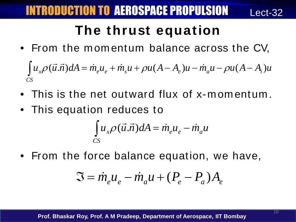
The thrust equation• From the momentum balance across the CV,
• This is the net outward flux of x-momentum.• This equation reduces to
• From the force balance equation, we have,
Prof. Bhaskar Roy, Prof. A M Pradeep, Department of Aerospace, IIT Bombay10
Lect-32
uAAuumuAAuumumdAnuu iaeseeCS
x )()().( −−−−++=∫ ρρρ
umumdAnuu aeeCS
x
−=∫ ).(ρ
eaeaee APPumum )( −+−=ℑ

The thrust equation• If we define fuel-air ratio,
• This is the generalised thrust equation for air-breathing engines.
• The term (Pe–Pa)Ae is not zero only if the exhaust jet is supersonic and the nozzle does not expand the exhaust jet to ambient pressure.
• However if Pa « Pe, it can be substantial contribution.
Prof. Bhaskar Roy, Prof. A M Pradeep, Department of Aerospace, IIT Bombay11
Lect-32
[ ] eaeea APPuufm )()1( −+−+=ℑ
af mmf /=
Engine performance parameters
• The engine performance is described by different efficiency definitions, thrust and the fuel consumption.
• The efficiency definitions that we shall now be discussing are applicable to an engine with a single propellant stream (turbojets or ramjets).
• For other types of jet engines (turbofan, turboprop) the equations need to be appropriately modified.
Prof. Bhaskar Roy, Prof. A M Pradeep, Department of Aerospace, IIT Bombay12
Lect-32

Engine performance parameters
• Propulsion efficiency: The ratio of thrust power to the rate of production of propellant kinetic energy.
• If we assume that f«1 and the pressure thrust term is negligible,
Prof. Bhaskar Roy, Prof. A M Pradeep, Department of Aerospace, IIT Bombay13
Lect-32
[ ]2/)2/)(1( 22 uufmu
eaP −+
ℑ=
η
e
e
e
eP uu
uuuu
uuu/1
/22/2/
)(22 +
=−−
=η

Engine performance parameters
• Thermal efficiency: The ratio of the rate of production of propellant kinetic energy to the total energy consumption rate
• For a turboprop or turboshaft engine, the output is largely shaft power. In this case,
Prof. Bhaskar Roy, Prof. A M Pradeep, Department of Aerospace, IIT Bombay14
Lect-32
[ ] [ ]
fuel. theofreaction ofheat theis , where,
2/)2/)(1(2/)2/)(1( 2222
R
R
e
Rf
eath
QfQ
uufQm
uufm −+=
−+=
η
engine. theofoutput power shaft theis , where, sRf
sth P
QmP
=η

Engine performance parameters
• Overall efficiency: The product of thermal efficiency and propulsion efficiency.
• In the case of aircraft that generate thrust using propellers,
Prof. Bhaskar Roy, Prof. A M Pradeep, Department of Aerospace, IIT Bombay15
Lect-32
thpo ηηη =
.efficiencypropeller theis Where, pr
thpro
η
ηηη =

Engine performance parameters• Thrust specific fuel consumption, TSFC
• For turbine engines that produce shaft power, brake specific fuel consumption, BSFC
• For engine (like turboprop) that produce both, equivalent brake specific fuel consumption,
Prof. Bhaskar Roy, Prof. A M Pradeep, Department of Aerospace, IIT Bombay16
Lect-32
[ ]uufmmm
TSFCea
ff
−+≈
ℑ=
)1(
s
f
Pm
BSFC
=
uPm
Pm
EBSFCs
f
es
f
ℑ+==

Ideal cycle for jet engines• All air-breathing jet engines operate on the
Brayton cycle (open cycle mode).• The most basic form of a jet engine is a
turbojet engine. • Some of the parameters of a jet engine cycle
are usually design parameters and hence often fixed a priori: eg. compressor pressure ratio, turbine inlet temperature etc.
• Cycle analysis involves determining the performance parameters of the cycle with the known design parameters.
Prof. Bhaskar Roy, Prof. A M Pradeep, Department of Aerospace, IIT Bombay17
Lect-32

Ideal cycle for jet engines
Prof. Bhaskar Roy, Prof. A M Pradeep, Department of Aerospace, IIT Bombay18
Lect-32
a 1 2 3 4 5 6 7
CompressorDiffuser
Combustion chamber/burner
Turbine
Afterburner
Nozzle
Schematic of a turbojet engine and station numbering scheme

Ideal cycle for jet engines• The different processes in a turbojet cycle are
the following:• a-1: Air from far upstream is brought to the
air intake (diffuser) with some acceleration/deceleration
• 1-2: Air is decelerated as is passes through the diffuser
• 2-3: Air is compressed in a compressor (axial or centrifugal)
• 3-4 The air is heated using a combustion chamber/burner
Prof. Bhaskar Roy, Prof. A M Pradeep, Department of Aerospace, IIT Bombay19
Lect-32

Ideal cycle for jet engines
• 4-5: The air is expanded in a turbine to obtain power to drive the compressor
• 5-6: The air may or may not be further heated in an afterburner by adding further fuel
• 6-7: The air is accelerated and exhausted through the nozzle.
Prof. Bhaskar Roy, Prof. A M Pradeep, Department of Aerospace, IIT Bombay20
Lect-32
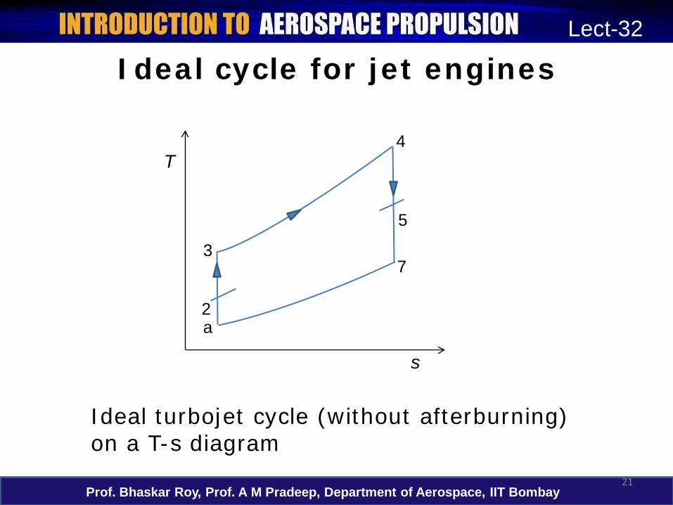
Ideal cycle for jet engines
Prof. Bhaskar Roy, Prof. A M Pradeep, Department of Aerospace, IIT Bombay21
Lect-32
s
T
2
4
5
3
a
7
Ideal turbojet cycle (without afterburning) on a T-s diagram

Ideal cycle for jet engines• For cycle analysis we shall take up each
component and determine the exit conditions based on known inlet parameters.
• Intake: Ambient pressure, temperature and Mach number are known, Pa, Ta and M
• Intake exit stagnation temperature and pressure are determined from the isentropic relations:
Prof. Bhaskar Roy, Prof. A M Pradeep, Department of Aerospace, IIT Bombay22
Lect-32
)1/(
0202
202 2
11
−
=
−+=
γγ
γ
aa
a
TTPP
MTT

Ideal cycle for jet engines• Compressor: Let the known compressor
pressure ratio be denoted as
• Combustion chamber: From energy balance,
• Hence, we can determine the fuel-air ratio.
Prof. Bhaskar Roy, Prof. A M Pradeep, Department of Aerospace, IIT Bombay23
Lect-32
( ) γγπ
π/)1(
0203
0203−=
=
c
c
TT
PPcπ
030403
0304
0304
//1/,
TTTcQTTfor
fQhh
pR
R
−−
=
+=

Ideal cycle for jet engines• Turbine: Since the turbine produces work to
drive the compressor, Wturbine = Wcompressor
Prof. Bhaskar Roy, Prof. A M Pradeep, Department of Aerospace, IIT Bombay24
Lect-32
0304
)1/(
04
050405
02030405
02030504
02030504
chamber, combustion idealan For
Hence,
)1/()()())(1(,
)()(
PPTTPP
fTTTTTTTTforTTcmTTcm papt
=
=
+−−=−=−+
−=−
−γγ

Ideal cycle for jet engines• Nozzle: With no afterburner, T06=T05, P06=P05
• Thrust, TSFC and efficiencies can now be determined using the formulae derived earlier.
Prof. Bhaskar Roy, Prof. A M Pradeep, Department of Aerospace, IIT Bombay25
Lect-32
( )[ ]γγ /)1(0606
0607
707
2
/12
Since,2
energy, kineticexit nozzle theTherefore,
−−=
=
−=
PPTcu
hh
hhu
ape
e

Ideal cycle for jet engines• Thrust,
•
• Propulsion efficiency,
• Thermal efficiency,
Prof. Bhaskar Roy, Prof. A M Pradeep, Department of Aerospace, IIT Bombay26
Lect-32
[ ]
[ ]uufmAPP
APPuufm
ea
eae
eaeea
−+=ℑ−
−+−+=ℑ
)1( ,negligible is )( If
)()1(
[ ]uufmmm
TSFCea
ff
−+≈
ℑ=
)1(
[ ]2/)2/)(1( 22 uufmu
eaP −+
ℑ=
η
[ ]R
eth fQ
uuf 2/)2/)(1( 22 −+=η

Ideal cycle for jet engines
Prof. Bhaskar Roy, Prof. A M Pradeep, Department of Aerospace, IIT Bombay27
Lect-32
s
T
2
4
5, 6
3
a
Ideal turbojet cycle with afterburning on a T-s diagram
6a
7a

Ideal cycle for jet engines• Afterburning: used when the aircraft needs a
substantial increment in thrust. For eg. to accelerate to and cruise at supersonic speeds.
• Since the air-fuel ratio in gas turbine engines are much greater than the stoichiometricvalues, there is sufficient amount of air available for combustion at the turbine exit.
• There are no rotating components like a turbine in the afterburner, the temperatures can be taken to much higher values than that at turbine entry.
Prof. Bhaskar Roy, Prof. A M Pradeep, Department of Aerospace, IIT Bombay28
Lect-32

Ideal cycle for jet engines• For calculating the fuel flow rate required to
achieve a temperature of T6a, we carry out an energy balance,
Prof. Bhaskar Roy, Prof. A M Pradeep, Department of Aerospace, IIT Bombay29
Lect-32
combustor.main in theratio flow fuel theis ratio, flow
fuel total theis, Where,
//1/,
1
21
050605
05062
20506
fffff
TTTcQTTfor
Qfhh
pR
a
Ra
+=
−−
=
+=

In this lecture ...• Ideal gas turbine cycles• Thrust and efficiency• The thrust equation• Other engine performance parameters• Ideal cycle for jet engines
– Turbojet engine – Turbojet engine with afterburning
Prof. Bhaskar Roy, Prof. A M Pradeep, Department of Aerospace, IIT Bombay30
Lect-32

In the next lecture ...
• Ideal cycle for jet engines– Turbofan engine – Different configurations of turbofan
engines– Turboprop engines– Turboshaft engines– Ramjets
Prof. Bhaskar Roy, Prof. A M Pradeep, Department of Aerospace, IIT Bombay31
Lect-32