minentprominent.us/promx/pdf/promus_english.pdf · ss1 316 stainless steel single ball check ......
TRANSCRIPT

Operating Instructions ProMinent® ProMus SeriesMetering Pumps
Two sets of operating instructions are required for the safe and correct operation of ProMinent® ProMus metering pumps:
This product-specifi c ProMus operating instructions manual and the “General operating instructions ProMinent® motor-driven metering pumps and hydraulic accessories”. Each is valid only when used in conjunction with the other.
Please completely read through these operating instructions fi rst! Do not discard! The warranty shall be invalidated by damage caused by operating errors!
ProMinent Fluid Controls, Inc. (USA) 136 Industry Drive, Pittsburgh, PA 15275ProMinent Fluid Controls Ltd. (CANADA) 490 Southgate Drive, Guelph, ON N1G 4P5
ProM
inent®
___ ___ ___ ___ ___ ___ ___ ___ ___ ___ ___ ___ ___
___ ___ ___ ___ ___ ___ ___ ___ ___ ___ ___ ___ ___Please enter identity code of the device here
ProMus: Rev #6 - NA 6/30/06

Publishing details:
Operating Instructions ProMinent® ProMus Series Metering Pumps © ProMinent Fluid Controls, Inc. (USA) © ProMinent Fluid Controls Ltd. (Canada)
ProMinent Fluid Controls, Inc. (USA) 136 Industry Drive, Pittsburgh, PA 15275 Tel: 412.787.2484 Fax: 412.787.0704 eMail: [email protected] www.prominent.us
ProMinent Fluid Controls Ltd. (Canada) 490 Southgate Drive, Guelph, ON N1G 4P5 Tel: 519.836.5692 Fax: 519.836.5226 eMail: [email protected] www.prominent.ca
Subject to technical modifications Printed in USA
Publishing details
ProMinent®Page 2

Table of contents
Page
Product Identification/Identity Code ................................................. 4
General User Instructions ................................................................ 5
1 About This Pump .................................................................. 6
2 Safety ..................................................................................... 6
3 Storage, Transport, Unpacking ............................................ 7
4 Functional Description .......................................................... 8
5 Device Overview / Control Elements .................................. 10
6 Assembly ............................................................................. 13
7 Installation ............................................................................. 13
7.1 Installation, Hydraulic ................................................... 13
7.2 Installation, Electrical .................................................... 14
8 Commissioning .................................................................... 14
9 Operation ............................................................................... 15
10 Maintenance .......................................................................... 16
11 Troubleshooting ................................................................... 18
12 Decommissioning And Disposal ......................................... 19
13 Technical Data ...................................................................... 20
14 Spare Parts And Accessories .............................................. 24
ProMinent® Page 3

Product Identification / Identity Code
Please enter the identity code given on the device label into the grey boxes below.
ProMinent®Page 4
Series: PROMUS1
Pump version:17A Size 17 liquid end with 3/8" Plunger17B Size 17 liquid end with 7/16" Plunger30A Size 30 liquid end with 5/8" Plunger30B Size 30 liquid end with 13/16" Plunger30C Size 30 liquid end with 1-1/8" Plunger40A Size 40 liquid end with 1-3/4" Plunger40B Size 40 liquid end with 2" Plunger40C Size 40 liquid end with 2-1/4" Plunger
Liquid end material:SS1 316 Stainless steel Single ball checkSS2 316 Stainless steel Double ball check (*Needed for applications above 500 psi)SS3 316 St. steel Single inlet, double outlet (Recommended for Flooded suction w/ discharge pressure above 500 psi)HC1 Hastelloy C Single ball checkHC2 Hastelloy C Double ball checkHC3 Hastelloy C Single inlet, double outlet (Recommended for Flooded suction with discharge pressure above 500 psi)A21 Alloy 20 single ball checkA22 Alloy 20 Double ball checkA23 Alloy 20 Single inlet, double outlet (Recommended for Flooded suction with discharge pressure above 500 psi)PVT PVDF/PTFE size 17 double inlet & outlet; sizes 30/40 single inlet & outlet
Connectors:0 Standard (In accordance with technical data)1 BSP taper
Base:0 Standard
Motor:X No motor includedD 1/2 HP TEFC Standard Motor
Stroke adjustment:1 Manual stroke adjustment7 Explosion proof stroke position motor (Nema 7)
Internal relief valve:A 3500 psi/size 17B 2080 psi/size 17C 1230 psi/size 17D 640 psi/size 17E 300 psi/size 17F 2080 psi/size 30G 1230 psi/size 30H 640 psi/size 30I 265 psi/sizes 30 & 40J 200 psi/sizes 30 & 40K 160 psi (30B,C & 40)L 230 psi/size 17M 230 psi/size 30N 230 psi/size 40
Gear ratio:01 12.5:1 56C02 15:1 56C03 30:1 56C04 40:1 56C05 50:1 56C06 12.5:1 IEC (IEC 71 with B5 flange)07 15:1 IEC (IEC 71 with B5 flange)08 30:1 IEC (IEC 71 with B5 flange)09 40:1 IEC (IEC 71 with B5 flange)
Hydraulic oil:0 Standard

General User Instructions
Please read through the following user instructions! They will enable you to gain the maximum benefi t from the operating instructions manual.
The following items are particularly highlighted in the text:
• Enumerated points
• Highlighted points
Operating instructions:
NOTE
Guidelines are intended to make your work easier.
Safety Guidelines:
WARNING
Describes a potentially dangerous situation. If not avoided, could jeopardize life and/or cause serious injury.
CAUTION
Describes a potentially dangerous situation. If not avoided, could result in lesser injuries or damage to property.
IMPORTANT
Describes a potentially damaging situation. If not avoided, could result in damage to property.
Observe also the instructions in the “General operating instructions manual for ProMinent® motor-driven metering pumps and hydraulic accessories”
In the event of complaint or a request for spare parts, quote the identity code and the serial number which you will fi nd on the device label. This will enable clear identifi cation of the pump type and material variant.
Only Explosion-proof Pumps:
The device label attached to the title page is identical to that supplied with the pump in order to facilitate selecting the correct operating instructions manual for the pump.
General User Instructions / Operating Instructions
ProMinent® Page 5
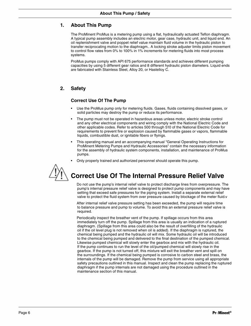
1. About This Pump
The ProMinent ProMus is a metering pump using a fl at, hydraulically actuated Tefl on diaphragm. A typical pump assembly includes an electric motor, gear case, hydraulic unit, and liquid end. An oil replenishment valve and poppet relief value maintain fl uid volume in the hydraulic piston to transfer reciprocating motion to the diaphragm.. A locking stroke adjuster limits piston movement to control fl ow rates from 0% to 100% in 1% increments for metering fl uids into most process systems.
ProMus pumps comply with API 675 performance standards and achieves different pumping capacities by using 5 different gear ratios and 8 different hydraulic piston diameters. Liquid ends are fabricated with Stainless Steel, Alloy 20, or Hastelloy C.
2. Safety
Correct Use Of The Pump
• Use the ProMus pump only for metering fl uids. Gases, fl uids containing dissolved gases, or solid particles may destroy the pump or reduce its performance.
• The pump must not be operated in hazardous areas unless motor, electric stroke control and any other electrical components and wiring comply with the National Electric Code and other applicable codes. Refer to articles 500 through 510 of the National Electric Code for requirements to prevent fi re or explosion caused by fl ammable gases or vapors, fl ammable liquids, combustible dust, or ignitable fi bers or fl yings.
• This operating manual and an accompanying manual "General Operating Instructions for ProMinent Metering Pumps and Hydraulic Accessories" contain the necessary information for the assembly of hydraulic system components, installation, and maintenance of ProMus pumps.
• Only properly trained and authorized personnel should operate this pump.
Correct Use Of The Internal Pressure Relief Valve Do not use the pump’s internal relief valve to protect discharge lines from overpressure. The
pump’s internal pressure relief valve is designed to protect pump components and may have setting that exceed safe pressures for the piping system. Install a separate external relief valve to protect the fl uid system from over pressure caused by blockage of the meter fl uid.v
After internal relief valve pressure setting has been exceeded, the pump will require time to balance pressure and pump to volume. To avoid this an external pressure relief valve is required.
Periodically inspect the breather vent of the pump. If spillage occurs from this area immediately turn off the pump. Spillage from this area is usually an indication of a ruptured diaphragm. (Spillage from this area could also be the result of overfi lling of the hydraulic oil if the oil level plug is not removed when oil is added). If the diaphragm is ruptured, the chemical being pumped and the hydraulic oil will mix. Some hydraulic oil will be introduced to the chemical being pumped and delivered to the fi nal destination of the pumped chemical.Likewise pumped chemical will slowly enter the gearbox and mix with the hydraulic oil. If the pump continues to run the level of the oil/pumped chemical will slowly rise in the gearbox. If the pump is not turned off, this mixture will exit the breather vent and spill on the surroundings. If the chemical being pumped is corrosive to carbon steel and brass, the internals of the pump will be damaged. Remove the pump from service using all appropriate safety precautions outlined in this manual. Inspect and clean the pump replacing the ruptured diaphragm if the pump internals are not damaged using the procedure outlined in the maintenance section of this manual.
About This Pump / Safety
ProMinent®Page 6

Safety/Storage, transport and unpacking
Safety Guidelines
WARNING
• Because the pump operates whenever the motor is energized, always take precautions to avoid personal injury or hazards from unexpected startup of the motor.
• Lock out pump motor before performing any maintenance on pump or pump system.
• Lockout the pump motor following a power failure, if such interuptions in pump function would create a hazard or cause damage to components.
• Periodically inspect for chemical leaks. Because this pump and its discharge operate continually under high pressure, system leaks may develop over time.
• Always de-pressurize the liquid end before performing any maintenance on the pump or system.
• Always empty and rinse pump liquid end before maintenance activities.
• Always wear appropriate protective equipment with performing pump maintenance.
• Keep pump accessible at all times for necessary operating and maintenance activities.
• Do not return pumps to ProMinent that have been used for radioactive chemicals.
CAUTION
• Use only components manufactured by Prominent for assembly, installation, or repair to avoid damage to pump components or personal injury.
• Before metering corrosive liquids, check compatibility in our resistance guide. (See the last catalog or www.prominent.us)
• The installation, operation and maintenance of ProMinent pumps may be subject to regulations set by state and federal agencies depending upon environmental conditions and the fl uid being handled. See the list of regulations agencies at the end of this document or consult your safety professional.
3 Storage, Transport And Unpacking
3.1 Storage• Prepare the pump for storage by fl ushing all chemicals from the liquid end and
replacing the oil breather cap (orange) with the shipping plug (no color specifi ed).
• Store in original shipping container if possible.
• Store pump in upright position in a dry, dust-free environment.
3.2 Transport• Replace oil breather cap (orange) with shipping plug (no color specifi ed) for transit.
• Transport in original container or container that will keep pump upright.
3.3 Unpacking• Inspect package before unpacking. If package is found to be damaged, notify
shipping company immediately
• After unpacking, mount pump on a secure, level surface.
• Save the shipping plug (no color specifi ed) and shipping container for possible future storage or transit.
ProMinent® Page 7

4 Functional description
General Description
The Prominent ProMus is a motor-driven metering pump incorporating a hydraulically balanced diaphragm. Pump energy comes from an electric motor that drives a worm gear in a cast iron drive case to rotate a cam. The cam gives linear motion to plunger hydraulically linked to the Teflon‘ Diaphragm. Movement of the plunger is controlled with a locking stroke adjuster to vary pump capacity from 0% to 100%. Pressures across the flat diaphragm, which separates hydraulic fluid from metered liquids, are balanced by a replenishment valve and a simple internal relief value. The replenishment valve adds fluids when needed, and the relief value continually circulates hydraulic fluid through the pump, removes of gases from hydraulic fluids, and limits hydraulic pressure.
Major Pump Components
The pump has four major components: driver, stroke adjuster, hydraulic system and liquid end
The Driver Component
The drive case includes an electric motor that is coupled to a hardened steel and bronze worm gear assembly to create rotational speeds needed for the cam. The cam is an eccentric needle cage-and-roller assembly that creates reciprocating motion and minimizes wear and heat at the cam-plunger interface. The cast iron case supports the worm gear, cam shaft and cam assembly and doubles as an reservoir for the hydraulic oil, which also serves as a lubricant for bearing and gears. A suction strainer within the drive case removes particulate from the oil before it enters the hydraulic system. The drive case also includes a sight tube for monitoring oil flow from the internal relief valve and an air bleed valve.
The Stroke Adjuster Component
The stroke adjuster controls pump output by altering the length of plunger stroke. The adjuster is a threaded rod that functions as stop to limit plunger movement on return strokes from 0% to 100% of cam movement. Position of the adjuster can be measured in 1% increments using a numerical scales stamped on the pump housing and 10-turn adjuster knob. A thumbscrew locks settings of the stroke adjuster knob.
Electrical stroke adjusters with 4 to 20mA output are available for remote control of flows in NEMA 4 and NEMA 7 environments.
The Hydraulic System Component
The hydraulic system consists of a fluid reservoir, a hydraulic piston and subassemblies that control and condition the fluid. The piston is composed of a plunger, return spring, and Teflon diaphragm, which also isolates hydraulic fluids from process fluids. An internal pressure relief/air bleed valve and oil replenishment check value remove entrained air and balance the pressure in the piston with pressures in the metered fluid. The system continuously cycles fresh oil through an oil replacement value and check valve.
Functional Description
ProMinent®Page 8

Internal Pressure Relief / Air Bleed Valve
The sole purpose for the adjustable pressure relief value is to protect drive components from damage caused by excessive pressures. To protect the system from overpressure an external pressure relief valve must be used. The valve contains a spring whose tension can be adjusted to select the pressure at which the poppet lifts from its seal and allows oil to return to the reservoir. The air bleed valve contains two opposing ball check valves that serve the purposes of removing air entrained in the hydraulic fluid and allowing a small amount of fluid to circulate through the system. The air bleed valve is located at the highest point in the hydraulic system where air would normally accumulate. After internal relief valve pressure setting has been exceeded, the pump will require time to balance pressure and pump to volume. To avoid this an external pressure relief valve is required.
Oil Replenishment Valve
The replenishment valve replaces oil lost through the air bleed value and maintains the consistent volume of fluid needed for metering accuracy. The valve is opened by the diaphragm when the volume of oil is low. .
Replenishment Check Valve
Located on the inlet of the hydraulic system, the replenishment check valve prevents back flow of hydraulic fluid during pumping strokes.
The Liquid End Component
All pump sizes are available in 316 SS, Alloy 20, Hastelloy and PVT in single ball. Size 17 and Size 30 metallic pumps are available with double ball configurations
Functional description
ProMinent® Page 9

5 Device Overview / Control Elements
Dimensional Drawing / ProMus Size 17
MinentP or
ProMinent®Page 10

5 Device Overview / Control Elements
Dimensional Drawing / ProMus Size 30
roP Minent
ProMinent® Page 11

Dimensional Drawing / ProMus Size 30
5 Device Overview / Control Elements
MinentP or
ProMinent®Page 12

Dimensional Drawing / ProMus Size 40
5 Device Overview / Control Elements
roP Minent
ProMinent® Page 13

Dimensional Drawing / ProMus Size 17
5 Device Overview / Control Elements
MinentP or
ProMinent®Page 14

Dimensional Drawing / ProMus Size 30
5 Device Overview / Control Elements
MinentP or
ProMinent® Page 15

5 Device Overview / Control Elements
Dimensional Drawing / ProMus Size 40
roP Minent
ProMinent®Page 16

6 Assembly
The ProMus pump is shipped complete from ProMinent and no assembly is required. A shipping plug must be removed from the oil fi ll/breather vent hole and replaced with the supplied orange breather vent plug.
If the pump was ordered without a liquid end, proceed to Changing the diaphragm located in the Maintenance section of this manual.
The pump must be mounted on a level, even, and stable surface using four 3/8” diameter bolts through holes in the pump base.
7 Installation
WARNING
Observe the guidelines "General operating instructions for ProMinent metering pumps and hydraulic accessories”, found in the operating instructions manual, particularly when pump applications are classifi ed as hazardous.
7.1 Installation, Hydraulic
WARNING
• Hazardous locations: Install an external pressure relief valve downstream from the liquid end to avoid potential hazards caused by blockage in the discharge line. In some environments, heat generated by excessive fl uid passing through the internal relief value may cause temperatures of the cast iron housing to reach dangerous levels.
• If the pump is to be used with chemicals that are reactive with water, be sure to remove any residue that may remain from factory testing. Feed low-pressure compressed air through the suction valve to purge water from the liquid end.
IMPORTANT
For chemicals with a particle size greater than 0.01 in. (0.3 mm), install a strainer in the suction line.
NOTE
If the metering pump discharges to atmospheric pressure, install a backpressure valve to create a minimum backpressure of approximately 22 PSI (1.5 bar).
Maximum admissible priming pressure (suction side): 14.5 PSI (1 bar).
Viscosity limits maximum 200 mPa-s (200 cP).
Assembly / Installation
ProMinent® Page 17

7.2 Installation, Electrical
WARNING
• Articles 500 through 510 of the National Electric Code cover the requirements for electrical equipment and wiring when fl ammable gases or vapors, fl ammable liquids, combustible dust, ignitable fi bers, or fl ying may create fi re or explosion hazards.
• For safe operation in hazardous environments, all electrical components, including motor, electric stroke control and other devices must be rated for hazardous areas as described in the National Electric Code.
IMPORTANT
Motor
• Read the "General Operating Instructions ProMinent Motor-Driven Metering Pumps and Hydraulic Accessories" which accompanies this manual, for placement of accessory items.
• Connect the motor using the information provided on the motor nameplate. Motor rotation should be counter clockwise looking down on motor (fan end). Also, read and follow additional instructions in manuals provided with the motor.
• For pumps with an electric stroke adjuster, follow any supplemental instructions provided for making electrical connections and operating the unit.
8 Commissioning
WARNING
Hazardous locations: when installing the metering pump in areas with potentials for explosion, observe related directives for installation covered the National Electric Code Articles 500 through 510.
IMPORTANT
Before beginning startup procedures:
• Check the breather vent has been installed. The pump is shipped with a plug on the breather vent and the cavity fi lled with oil, which must be removed prior to installation.
• Check that pump capabilities are not exceeded when metering highly viscous or dense chemicals.
• Check that liquid end materials are chemically resistant to the metered fl uid (see the resistance list on line at www.prominent.us or the latest catalog)
Venting The Liquid End To Prime The Pump
Priming the pump may require venting the discharge line to atmospheric pressure to purge air from the liquid end and fi ll cavities with metered fl uid before applying high pressure.
Installation / Commissioning
ProMinent®Page 18

Promus Pump Startup Guide
TO BE USED FOR INITIAL INSTALLATION
WARNING
• Always wear appropriate protective equipment when working with hazardous chemicals.
• Detach the discharge line or use a separate priming valve that discharges to atmospheric pressure.
• Energize the pump and allow it to run until the metered fl uid appears on the discharge side of the liquid end.
• Re-attach the discharge line or close priming valve.
• Pump is now ready for normal operation.
9 Operation
Pump output can be adjusted using a mechanical or electronic stroke adjuster mounted on the pump.
Pump output can also be adjusted by stroke frequency, if the pump is supplied with a variable speed motor. If such is the case, follow manufacturer’s instructions for the motor drive.
10 Maintenance
WARNING
• Always wear appropriate protective equipment when working with hazardous chemicals.
• Always de-pressurize the liquid end before undertaking maintenance on the pump or pump system.
• Only trained and authorized personnel should maintain and repair pumps and accessories.
• Follow lockout procedures to prevent unauthorized personnel from energizing pumps during maintenance.
• Hazardous locations: Additional safety regulations and procedures may apply for pumps in areas classifi ed as hazardous.
NOTE
• Keep a set of spare parts in stock for maintenance work on each liquid end.
Maintenance tasks
Initial Three Months
A shorter maintenance interval may be required for systems under heavy load (e.g. continuous operation, high system pressures, or abrasive media).
• Check torque of the liquid end bolts and re-torque if necessary.
Metallic Liquid end 1/2” Bolts:90-120 ft.lbs (149-163 N m)
Plastic Liquid end 1/2” Bolts:20-30 ft.lbs (27-41 N m)
Metallic Liquid end 5/16” Bolts:35 ft.lbs (47 N m)
Plastic Liquid end 5/16” Bolts:20 ft.lbs (27 N m)
• Check discharge and suction valves for chemical leakage
Startup Guide / Operation
ProMinent® Page 19
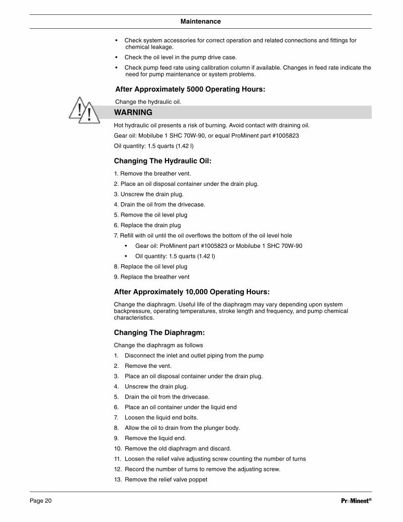
WARNING
Hot hydraulic oil presents a risk of burning. Avoid contact with draining oil.
Gear oil: Mobilube 1 SHC 70W-90, or equal ProMinent part #1005823
Oil quantity: 1.5 quarts (1.42 l)
Changing The Hydraulic Oil:
1. Remove the breather vent.
2. Place an oil disposal container under the drain plug.
3. Unscrew the drain plug.
4. Drain the oil from the drivecase.
5. Remove the oil level plug
6. Replace the drain plug
7. Refi ll with oil until the oil overfl ows the bottom of the oil level hole
• Gear oil: ProMinent part #1005823 or Mobilube 1 SHC 70W-90
• Oil quantity: 1.5 quarts (1.42 l)
8. Replace the oil level plug
9. Replace the breather vent
After Approximately 10,000 Operating Hours:
Change the diaphragm. Useful life of the diaphragm may vary depending upon system backpressure, operating temperatures, stroke length and frequency, and pump chemical characteristics.
Changing The Diaphragm:
Change the diaphragm as follows
1. Disconnect the inlet and outlet piping from the pump
2. Remove the vent.
3. Place an oil disposal container under the drain plug.
4. Unscrew the drain plug.
5. Drain the oil from the drivecase.
6. Place an oil container under the liquid end
7. Loosen the liquid end bolts.
8. Allow the oil to drain from the plunger body.
9. Remove the liquid end.
10. Remove the old diaphragm and discard.
11. Loosen the relief valve adjusting screw counting the number of turns
12. Record the number of turns to remove the adjusting screw.
13. Remove the relief valve poppet
Maintenance
• Check system accessories for correct operation and related connections and fi ttings for chemical leakage.
• Check the oil level in the pump drive case.
• Check pump feed rate using calibration column if available. Changes in feed rate indicate the need for pump maintenance or system problems.
After Approximately 5000 Operating Hours:
Change the hydraulic oil.
ProMinent®Page 20

14. Insert the new diaphragm in the counterbore of the liquid end.
15. Reinstall the liquid end taking care that the diaphragm stays in the counterbore
16. Tighten the liquid end bolts to the specifi ed torque.
17. Replace the oil drain plug
18. Refi ll with oil until the oil just overfl ows the bottom of the oil level hole.
19. Replace the oil level plug
20. Replace the breather vent
Prime the hydraulic system as follows
1. Slowly add oil to the relief valve threaded hole while running the pump to purge the air from the hydraulic system.
2. Turn the pump off
3. Reinstall the spring and poppet.
4. Reinstall the relief valve adjusting screw to it’s original position counting the number of recorded turns above
5. Reconnect the pump to the process piping
6. Check the oil level in the drivecase and add oil if necessary
7. Reprime the pump per the commissioning procedure
8. Check for proper operation by observing the “heartbeat” action of fl uid in the sight tube for the relief/air bleed valve .
IMPORTANT
The diaphragm can never be reused once it is removed from the pump.
ProMus Pump Startup Guide
TO BE USED ONLY AFTER THE DIAPHRAGM HAS BEEN REMOVED OR CHANGED DURING MAINTENANCE. THIS PROCEDURE DOES NOT APPLY FOR NEW OR FACTORY REBUILT PUMPS.
CAUTION:
The pump must be primed before it is returned to service under system pressure. If the liquid end does not contain media when placed under pressure, damage to the diaphragm may occur.
1. Install high pressure piping and hoses on the suction and discharge sides of the pump.
2. Reduce the pressure on the diaphragm to atmospheric pressure by adjusting the poppet relief valve. Remove the plug seal on the adjusting screw tower, and using a fl athead screw drive, turn the poppet adjustment screw counterclockwise until there is no tension on the poppet valve spring.
3. Supply media through the suction line and fl ow media until all the air has been purged from the liquid end and discharge lines
4. Warning: Before proceeding further, check that the clear sight cover is tightly secured to the pump housing before starting the pump. The cover may be loosened by fl uid percolating through the site tube when the system was depressurized.
5. Start the pump and use the following procedure to reset output pressure and pressure balance on the diaphragm:
a. Slowly apply backpressure on the discharge line.
b. Turn the poppet adjusting screw clockwise (tighten) until return fl ow in the sight tube
Maintenance
ProMinent® Page 21

Troubleshooting
slows to a pulse. Advance the screw 1/2 turn
c Increase backpressure on the discharge line until the relief valve lifts.
d. Repeat steps b and c until the desired discharge pressure is achieved. At that pressure set the adjusting screw within ±1/2 turn of stopping the fl ow.
6. Allow the pump to run for an hour to allow the air relief valve and diaphragm to fl ex. If a increased fl ow becomes apparent in the sight tube, tighten the adjustment screw no more than 1/2 additional turn.
7 Insert the plug seal back on the adjusting screw tower.
11 Troubleshooting
WARNING
• Always wear appropriate protective equipment when working with hazardous chemicals
• Always depressurize the suction and discharge lines before working on the pump.
• Always empty and rinse the liquid end before maintenance and repair work!
Pump Fails To Meter Liquid To Pump Specifi cation
or
Pump Does Not Prime Despite Full Stroke Action And Venting
Cause: Valves dirty or worn
Remedy: Overhaul valves (see "Overhaul valves", "Repair" section)
Cause: Internal relief valve open
Remedy: Unscrew knurled screw in bypass valve
Cause: Internal relief valve heavily worn as discharge line blocked or constricted
Remedy: Replace bypass valve and remove blockage from discharge line
Cause: Hydraulic oil low
Remedy: Add hydraulic oil until oil level has reached inspection port on the side of the pump housing (see "Replace Diaphragm":, "Maintenance" section)
Cause: Electrical connections to motor
Remedy: 1. Verify voltage and frequency
2. Check motor connections
Power End Motor Very Hot
Cause: Discharge line greatly constricted
Remedy: 1. Remove blockage from discharge line
2. Check bypass valve
ProMinent®Page 22

Decommissioning And Disposal
12 Decommissioning And Disposal
Decommissioning
WARNING
• Always wear appropriate protective equipment when working with hazardous chemicals
• Before working on any pump, disconnect electrical power sources and lockout or tagout switches that could accidentally energize the motor.
• Always depressurize the suction and discharge lines before working on the pump.
• Risk of burning by hot hydraulic oil. Avoid contact with draining oil until housing is cool.
• When decommissioning pump, clean housing and liquid end thoroughly to remove all dirt and chemicals.
Final Decommissioning
• Disconnect pump from power supply
• Rinse the liquid end with a suitable cleaning agent, and clean thoroughly if the pump has been used with hazardous materials
• Drain hydraulic oil.
Temporary Decommissioning
• Disconnect pump from power supply
• Rinse the liquid end with a suitable cleaning agent, clean thoroughly if the pump has been used with hazardous materials
• Drain hydraulic oil.
• Place valve covers on valves
• Place the pump on a pallet if possible
• Store the pump in a dry enclosed area indoors under ambient conditions
Storage temperature: 15 °F (-10 °C) to 125 °F (52 °C)
Air humidity: max. 95%, non-condensing
Disposal
IMPORTANT
Observe all current local, state/provincial and federal directives that apply to disposal of pumps, pump components, and waste products. Give particular attention to waste oils and electronic materials.
ProMinent® Page 23

13 Technical Data
Priming Lift
The priming lift is 5 feet (1.5 m). (Determined for 68 ºF (20 ºC) water with liquid end and suction line empty and clean moistened valves.)
Suction Lift
The suction lift is 7.5 feet (2.3m) (Determined for 68 ºF (20 ºC) water with liquid end and suction line filled and a suction line with adequate cross section.)
Priming Pressure
The maximum allowable priming pressure is 14.5 psi (1 bar)
Internal Hydraulic Pressure Relief Valve
The internal relief valve is set to 10% over the pressures listed in the following chart.
Pump Accuracy
Steady state flow accuracy is +/- 1% over a turndown ratio of 10:1
The flow repeatability is +/- 3% over the specified turn down ratio.
Deviation from linearity does not exceed +/- 3% of the rated flow over the specified turn down ratio
Viscosity
Viscosity limit without valve 200 mPa-s (200 cP)
Liquid End Materials of Construction
Stainless Steel ASTM A276 Type 316
Hastelloy C
Alloy 20
PVT
Hydraulic Oil
Type Mobilube SHC 75w-90 Prominent Part Number 1005823
Quantity 1.5 Quart (1.42 l)
Technical Data
ProMinent®Page 24

Temperature Range
Storage 15 °F (-10 °C) to 125 °F (52 °C)
Operating 15 °F (-10 °C) to 105 °F (40 °C)
Maximum Pumped Fluid Temperature
Maximum Pumped Fluid Temperature (Metallic Liquid Ends Only)
Continous 195F (90C)
Intermitent 250F (121C)
Maximum Pumped Fluid Temperature (Plastic Liquid Ends)
Continuous 95F (35C)
EnvironmentalPermissible air humidity 95% non- condensing
Chemical Resistance See our latest product catalog or www.prominent.us.
Applicable Standards
API 675 (built in accordance to API 675 standards)
National Fire Protection Association (NFPA)
National Electric Manufactures Association (NEMA)
Occupational Safety and Health Administration (OSHA)
Technical Data
ProMinent® Page 25
At 60 Hz (1750rpm) Max At 50 Hz (1458 rpm) Typical
Capacity at Max. Gear Stroke Capacity at Max. suct./dis.
Backpressure Ratio Rate Backpressure Connection
U.S. Stroke/ U.S. Stroke/ Max
Plunger (in.) psig GPH l/h min. GPH l/h min. bar MNPT
3/8” Plunger 232 0.61 2.3 50 35 * * * *
3/8” Plunger 232 0.76 2.8 40 43 0.63 2.45 36 16 1/4
3/8” Plunger 232 1.02 3.8 30 58 0.85 3.29 48 16 1/4
3/8” Plunger 232 2.03 7.6 15 115 1.69 6.56 96 16 1/4
3/8” Plunger 232 2.44 9.2 12.5 138 2.03 7.88 115 16 1/4
7/16” Plunger 232 0.83 3.1 50 35 * * * *
7/16” Plunger 232 1.04 3.9 40 43 0.87 3.36 36 16 1/4
7/16” Plunger 232 1.38 5.2 30 58 1.15 4.46 48 16 1/4
7/16” Plunger 232 2.77 10.4 15 115 2.31 8.94 96 16 1/4
7/16” Plunger 232 3.32 12.5 12.5 138 2.77 10.72 115 16 1/4
5/8” Plunger 232 1.8 6.8 50 35 * * * *
5/8” Plunger 232 2.25 8.5 40 43 1.87 7.26 36 16 1/2
5/8” Plunger 232 3 11.3 30 58 2.5 9.68 48 16 1/2
5/8” Plunger 232 6 22.7 15 115 5 19.37 96 16 1/2
5/8” Plunger 232 7.2 27.2 12.5 138 6 23.24 115 16 1/2
13/16” Plunger 232 3.04 11.5 50 35 * * * *
13/16” Plunger 232 3.8 14.3 40 43 3.17 12.27 36 16 1/2
13/16” Plunger 232 5.07 19.1 30 58 4.22 16.37 48 16 1/2
13/16” Plunger 232 10.1 38.2 15 115 8.45 32.73 96 16 1/2
13/16” Plunger 232 12.2 46.1 12.5 138 10.14 39.28 115 16 1/2
1-1/8” Plunger 232 6.34 24 50 35 * * * * 1/2
1-1/8” Plunger 232 7.93 30 40 43 6.61 25.61 36 16 1/2
1-1/8” Plunger 232 10.6 40.1 30 58 8.81 34.14 48 16 1/2
1-1/8” Plunger 232 21.1 79.8 15 115 17.62 68.29 96 16 1/2
1-1/8” Plunger 232 25.4 96.1 12.5 138 21.15 81.95 115 16 1/2
1-3/4” Plunger 232 15.4 58.2 50 35 * * * *
1-3/4” Plunger 232 19.2 72.6 40 43 15.99 61.97 36 16 3/4
1-3/4” Plunger 232 25.6 96.9 30 58 21.32 82.62 48 16 3/4
1-3/4” Plunger 232 51.2 193.8 15 115 42.64 165.24 96 16 3/4
1-3/4” Plunger 232 61.4 232.4 12.5 138 51.17 198.29 115 16 3/4
2” Plunger 200 20.1 76 50 35 * * * *
2” Plunger 200 25.1 95 40 43 20.89 80.94 36 14 3/4
2” Plunger 200 33.4 126.4 30 58 27.85 107.91 48 14 3/4
2” Plunger 200 66.8 252.8 15 115 55.7 215.83 96 14 3/4
2” Plunger 200 80.2 303.5 12.5 138 66.84 258.99 115 14 3/4
2-1/4” Plunger 160 25.4 96.1 50 35 * * * *
2-1/4” Plunger 160 31.7 119.9 40 43 26.43 102.43 36 11 3/4
2-1/4” Plunger 160 42.3 160.1 30 58 35.25 136.58 48 11 3/4
2-1/4” Plunger 160 84.6 327.8 15 115 70.49 273.16 96 11 3/4
2-1/4” Plunger 160 101.5 384.2 12.5 138 84.59 327.79 115 11 3/4
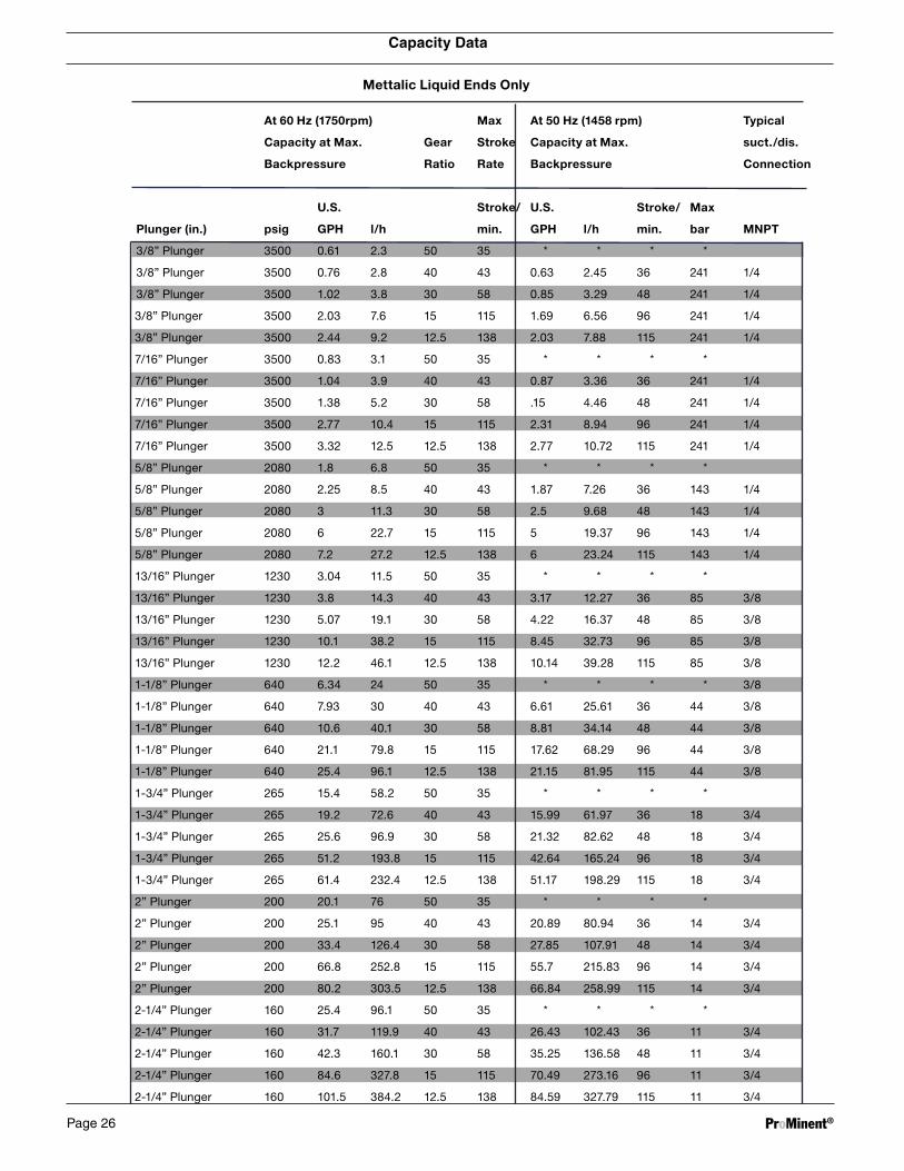
Capacity Data
Mettalic Liquid Ends Only
At 60 Hz (1750rpm) Max At 50 Hz (1458 rpm) Typical
Capacity at Max. Gear Stroke Capacity at Max. suct./dis.
Backpressure Ratio Rate Backpressure Connection
U.S. Stroke/ U.S. Stroke/ Max
Plunger (in.) psig GPH l/h min. GPH l/h min. bar MNPT
3/8” Plunger 3500 0.61 2.3 50 35 * * * *
3/8” Plunger 3500 0.76 2.8 40 43 0.63 2.45 36 241 1/4
3/8” Plunger 3500 1.02 3.8 30 58 0.85 3.29 48 241 1/4
3/8” Plunger 3500 2.03 7.6 15 115 1.69 6.56 96 241 1/4
3/8” Plunger 3500 2.44 9.2 12.5 138 2.03 7.88 115 241 1/4
7/16” Plunger 3500 0.83 3.1 50 35 * * * *
7/16” Plunger 3500 1.04 3.9 40 43 0.87 3.36 36 241 1/4
7/16” Plunger 3500 1.38 5.2 30 58 .15 4.46 48 241 1/4
7/16” Plunger 3500 2.77 10.4 15 115 2.31 8.94 96 241 1/4
7/16” Plunger 3500 3.32 12.5 12.5 138 2.77 10.72 115 241 1/4
5/8” Plunger 2080 1.8 6.8 50 35 * * * *
5/8” Plunger 2080 2.25 8.5 40 43 1.87 7.26 36 143 1/4
5/8” Plunger 2080 3 11.3 30 58 2.5 9.68 48 143 1/4
5/8” Plunger 2080 6 22.7 15 115 5 19.37 96 143 1/4
5/8” Plunger 2080 7.2 27.2 12.5 138 6 23.24 115 143 1/4
13/16” Plunger 1230 3.04 11.5 50 35 * * * *
13/16” Plunger 1230 3.8 14.3 40 43 3.17 12.27 36 85 3/8
13/16” Plunger 1230 5.07 19.1 30 58 4.22 16.37 48 85 3/8
13/16” Plunger 1230 10.1 38.2 15 115 8.45 32.73 96 85 3/8
13/16” Plunger 1230 12.2 46.1 12.5 138 10.14 39.28 115 85 3/8
1-1/8” Plunger 640 6.34 24 50 35 * * * * 3/8
1-1/8” Plunger 640 7.93 30 40 43 6.61 25.61 36 44 3/8
1-1/8” Plunger 640 10.6 40.1 30 58 8.81 34.14 48 44 3/8
1-1/8” Plunger 640 21.1 79.8 15 115 17.62 68.29 96 44 3/8
1-1/8” Plunger 640 25.4 96.1 12.5 138 21.15 81.95 115 44 3/8
1-3/4” Plunger 265 15.4 58.2 50 35 * * * *
1-3/4” Plunger 265 19.2 72.6 40 43 15.99 61.97 36 18 3/4
1-3/4” Plunger 265 25.6 96.9 30 58 21.32 82.62 48 18 3/4
1-3/4” Plunger 265 51.2 193.8 15 115 42.64 165.24 96 18 3/4
1-3/4” Plunger 265 61.4 232.4 12.5 138 51.17 198.29 115 18 3/4
2” Plunger 200 20.1 76 50 35 * * * *
2” Plunger 200 25.1 95 40 43 20.89 80.94 36 14 3/4
2” Plunger 200 33.4 126.4 30 58 27.85 107.91 48 14 3/4
2” Plunger 200 66.8 252.8 15 115 55.7 215.83 96 14 3/4
2” Plunger 200 80.2 303.5 12.5 138 66.84 258.99 115 14 3/4
2-1/4” Plunger 160 25.4 96.1 50 35 * * * *
2-1/4” Plunger 160 31.7 119.9 40 43 26.43 102.43 36 11 3/4
2-1/4” Plunger 160 42.3 160.1 30 58 35.25 136.58 48 11 3/4
2-1/4” Plunger 160 84.6 327.8 15 115 70.49 273.16 96 11 3/4
2-1/4” Plunger 160 101.5 384.2 12.5 138 84.59 327.79 115 11 3/4
ProMinent®Page 26

Capacity Data
Plastic Liquid Ends Only
At 60 Hz (1750rpm) Max At 50 Hz (1458 rpm) Typical
Capacity at Max. Gear Stroke Capacity at Max. suct./dis.
Backpressure Ratio Rate Backpressure Connection
U.S. Stroke/ U.S. Stroke/ Max
Plunger (in.) psig GPH l/h min. GPH l/h min. bar MNPT
3/8” Plunger 232 0.61 2.3 50 35 * * * *
3/8” Plunger 232 0.76 2.8 40 43 0.63 2.45 36 16 1/4
3/8” Plunger 232 1.02 3.8 30 58 0.85 3.29 48 16 1/4
3/8” Plunger 232 2.03 7.6 15 115 1.69 6.56 96 16 1/4
3/8” Plunger 232 2.44 9.2 12.5 138 2.03 7.88 115 16 1/4
7/16” Plunger 232 0.83 3.1 50 35 * * * *
7/16” Plunger 232 1.04 3.9 40 43 0.87 3.36 36 16 1/4
7/16” Plunger 232 1.38 5.2 30 58 1.15 4.46 48 16 1/4
7/16” Plunger 232 2.77 10.4 15 115 2.31 8.94 96 16 1/4
7/16” Plunger 232 3.32 12.5 12.5 138 2.77 10.72 115 16 1/4
5/8” Plunger 232 1.8 6.8 50 35 * * * *
5/8” Plunger 232 2.25 8.5 40 43 1.87 7.26 36 16 1/2
5/8” Plunger 232 3 11.3 30 58 2.5 9.68 48 16 1/2
5/8” Plunger 232 6 22.7 15 115 5 19.37 96 16 1/2
5/8” Plunger 232 7.2 27.2 12.5 138 6 23.24 115 16 1/2
13/16” Plunger 232 3.04 11.5 50 35 * * * *
13/16” Plunger 232 3.8 14.3 40 43 3.17 12.27 36 16 1/2
13/16” Plunger 232 5.07 19.1 30 58 4.22 16.37 48 16 1/2
13/16” Plunger 232 10.1 38.2 15 115 8.45 32.73 96 16 1/2
13/16” Plunger 232 12.2 46.1 12.5 138 10.14 39.28 115 16 1/2
1-1/8” Plunger 232 6.34 24 50 35 * * * * 1/2
1-1/8” Plunger 232 7.93 30 40 43 6.61 25.61 36 16 1/2
1-1/8” Plunger 232 10.6 40.1 30 58 8.81 34.14 48 16 1/2
1-1/8” Plunger 232 21.1 79.8 15 115 17.62 68.29 96 16 1/2
1-1/8” Plunger 232 25.4 96.1 12.5 138 21.15 81.95 115 16 1/2
1-3/4” Plunger 232 15.4 58.2 50 35 * * * *
1-3/4” Plunger 232 19.2 72.6 40 43 15.99 61.97 36 16 3/4
1-3/4” Plunger 232 25.6 96.9 30 58 21.32 82.62 48 16 3/4
1-3/4” Plunger 232 51.2 193.8 15 115 42.64 165.24 96 16 3/4
1-3/4” Plunger 232 61.4 232.4 12.5 138 51.17 198.29 115 16 3/4
2” Plunger 200 20.1 76 50 35 * * * *
2” Plunger 200 25.1 95 40 43 20.89 80.94 36 14 3/4
2” Plunger 200 33.4 126.4 30 58 27.85 107.91 48 14 3/4
2” Plunger 200 66.8 252.8 15 115 55.7 215.83 96 14 3/4
2” Plunger 200 80.2 303.5 12.5 138 66.84 258.99 115 14 3/4
2-1/4” Plunger 160 25.4 96.1 50 35 * * * *
2-1/4” Plunger 160 31.7 119.9 40 43 26.43 102.43 36 11 3/4
2-1/4” Plunger 160 42.3 160.1 30 58 35.25 136.58 48 11 3/4
2-1/4” Plunger 160 84.6 327.8 15 115 70.49 273.16 96 11 3/4
2-1/4” Plunger 160 101.5 384.2 12.5 138 84.59 327.79 115 11 3/4
ProMinent® Page 27

Spare Parts and Accessories
SIZE 17 SINGLE BALL LIQUID END P\N 853500
1
6
7
3
9
5
2
8
4
ProMinent®Page 28

Spare Parts and Accessories
SIZE 17 SINGLE BALL LIQUID END P\N 853500
ItemNumber
Quantity PartNumber
Title
1 1 853200 LIQUID END, SIZE 17, 316SST
2 3 853209 SEAL, CHECK VALVE SIZE17, SKIVE CUT TEFLON
3 1 853203 SEAT, UPPER CHECKVALVE, SIZE 17
4 2 853211 BALL, 1/4 316 SST, SIZE 17
5 2 853208 GUIDE, CHECK VALVE BALL,SIZE 17, 316 SST
6 2 853201 PIN, BALL GUIDE, SIZE 17,1/8 DIA. x 1/2 LONG, 316SST
7 2 853202 CAP, CHECK VALVE, SIZE 17,316 SST
8 1 853210 DIAPHRAGM, SIZE 17, GYLONTYPE 3522
9 1 853204 SEAT, LOWER CHECKVALVE, SIZE 17, 316 SST
LIQUID END SPARE PARTS KIT ORDER P\N 853503
ProMinent® Page 29

1
11
4
3
12
7
13
10
2
9
6
SIZE 17 DOUBLE BALL LIQUID END P\N 853501
Spare Parts and Accessories
ProMinent®Page 30

SIZE 17 DOUBLE BALL LIQUID END P\N 853501
ItemNumber
Quantity PartNumber
Title
1 1 853200 LIQUID END, SIZE 17, 316SST
2 6 853209 SEAL, CHECK VALVE SIZE17, SKIVE CUT TEFLON
3 2 853203 SEAT, UPPER CHECKVALVE, SIZE 17
4 2 853202 CAP, CHECK VALVE, SIZE 17,316 SST
6 4 853211 BALL, 1/4 316 SST, SIZE 17
7 1 853206 CAP, UPPER, DOUBLE BALL,SIZE 17, 316 SST
9 1 853210 DIAPHRAGM, SIZE 17, GYLONTYPE 3522
10 4 853208 GUIDE, CHECK VALVE BALL,SIZE 17, 316 SST
11 4 853201 PIN, BALL GUIDE, SIZE 17,1/8 DIA. x 1/2 LONG, 316SST
12 2 853204 SEAT, LOWER CHECKVALVE, SIZE 17, 316 SST
13 1 853207 CAP, LOWER, DOUBLE BALL,SIZE 17, 316 SST
LIQUID END SPARE PARTS KIT ORDER P\N 853504
Spare Parts and Accessories
ProMinent® Page 31

6 1
4
8
3
7
5
2
SIZE 30 LIQUID END P\N 854500
Spare Parts and Accessories
ProMinent®Page 32

SIZE 30 LIQUID END P\N 854500
ItemNumber
Quantity PartNumber
Title
1 1 854203 LIQUID END, SIZE 30, 316SST
2 3 854210 SEAL, CHECK VALVE SIZE30, TEFLON
3 1 854207 SEAT,UPPER CHECK VALVE,SIZE 30, 316 SST
4 2 854205 GUIDE, CHECK VALVE BALL,SIZE 30
5 2 854209 CAP, CHECK VALVE, SIZE30, 316 SST
6 1 854201 DIAPHRAGM, SIZE 30, GYLONTYPE 3522
7 1 854208 SEAT, LOWER CHECKVALVE, SIZE 30, 316 SST
8 2 854206 BALL, 7/16 316 SST, SIZE30
LIQUID END SPARE PARTS KIT ORDER P\N 854501
Spare Parts and Accessories
ProMinent® Page 33

17
6
4
5
3
2
SIZE 40 LIQUID END P\N 855500
Spare Parts and Accessories
ProMinent®Page 34

SIZE 40 LIQUID END P\N 855500
ItemNumber
Quantity PartNumber
Title
1 1 855200 LIQUID END, SIZE 40, 316SST
2 2 855208 GUIDE, CHECK VALVE BALL,SIZE 40
3 2 855207 SEAL, CHECK VALVE SIZE40, TEFLON
4 2 855205 CAP, CHECK VALVE, SIZE40, 316 SST
5 2 855206 SEAT, CHECK VALVE, SIZE40, 316 SST
6 2 855204 BALL, 3/4 316 SST, SIZE 40
7 1 855201 DIAPHRAGM, SIZE 40, GYLONTYPE 3522
LIQUID END SPARE PARTS KIT ORDER P\N 855501
Spare Parts and Accessories
ProMinent® Page 35

Spare Parts and Accessories
BOM Description Extended Description
851763 Drivecase 56C Rebuild Kit Rebuild Kit Drivecase 56c
851764 Drivecase IEC Rebuild Kit Rebuild Kit Drivecase IEC
852751 Rebuild Kit Manual Stroke Adjuster Rebuild Kit Manual Stroke Adjuster
852753 Nema 7 Electric Stroke Adjuster Reb/Kit Rebuild Kit, Electric Stroke Adjuster Nema 7
853755 Sz 17 Hydraulics 3/8 Plunger Rebuild Kit Sz 17 Hydraulics 3/8 Plunger Rebuild Kit
853756 Sz 17 Hydraulics 7/16 Plunger Rebuild Kit Sz 17 Hydraulics 7/16 Plunger Rebuild Kit
854756 Sz 30 Hydraulics 5/8 Plunger Rebuild Kit Rebuild Kit Size 30 Hydraulics 5/8 Plunger
854757 Sz 30 Hydraulics 13/16 Plunger Rebuild Kit Rebuild Kit Size 30 Hydraulics 13/16 Plunger
854758 Sz 30 Hydraulics 1 1/8 Plunger Rebuild Kit Rebuild Kit Size 30 Hydraulics 1 1/8 Plunger
855754 Sz 40 Hydraulics 1 3/4 Plunger Rebuild Kit Rebuild Kit Size 40 Hydraulics 1 3/4 Plunger
855755 Sz 40 Hydraulics 2 Plunger Rebuild Kit Rebuild Kit Size 40 Hydraulics 2 Plunger
855756 Sz 40 Hydraulics 2 1/4 Plunger Rebuild Kit Rebuild Kit Size 40 Hydraulics 2 1/4 Plunger
853502 SP-Kit LE 17 SS Rebuild Kit Liquid End Size 17 Single Ball 316SS
853503 SP- Kit LE 17 SS Dbl I/O Rebuild Kit Liquid End Size 17 Double Ball 316SS
853505 SP-Kit LE 17 SS Dbl Out Rebuild Kit Liquid End Size 17 Double Ball 316SS Out Only
853582 SP-Kit LE 17 A2 Rebuild Kit Liquid End Size 17 Single Ball Alloy 20
853583 SP-Kit LE 17 A2 Dbl I/O Rebuild Kit, Liquid End, Size 17, Double Ball Alloy 20
853585 SP-Kit LE 17 A2 Dbl Out Rebuild Kit, Liquid End, Size 17, Double Ball, Out Only, Alloy 20
853662 SP-Kit LE 17 HC Rebuild Kit, Liquid End, Size 17, Single Ball, Hastelloy C-276
853663 SP-Kit LE 17 HC Dbl I/O Rebuild Kit, Liquid End, Size 17, Double Ball, Hastelloy C-276
853665 SP-Kit LE 17 HC Dbl Out Rebuild Liquid End Kit Size 17 Double Ball Out Only Hastelloy C-276
854501 SP-Kit LE 30 SS Rebuild Kit Liquid End Size 30 Single Ball 316SS
854503 SP-Kit LE 30 SS Dbl I/O Rebuild Kit, Liquid End, Size 30, Double Ball 30/30 In & Out, 316SS
854505 SP-Kit LE 30 SS Dbl O 30/17 Rebuild Kit, Liquid End, Size 30, Double Ball, 30/17, Out Only, 316SS
854507 SP-Kit LE 30 SS Dbl O 30/30 Rebuild Kit, Liquid End, Size 30, Double Ball, Out Only, 316SS
854509 SP-Kit LE 30 SS Dbl O 30/17 Rebuild Kit, Liq End 30 Dbl Ball In&Out 30/17 316SS
854601 SP-Kit LE 30 A2 Rebuild Kit, Liquid End Size 30, Single Ball Alloy 20
854603 SP-Kit LE 30 A2 Dbl I/O Rebuild Kit, Liq End 30 Dbl Ball In&Out 30/30 Alloy 20
854605 SP-Kit LE 30 A2 Dbl O 30/17 Rebuild Kit, Liq End 30 Dbl Ball Out Only 30/17 Alloy 20
854607 SP-Kit LE 30 A2 Dbl O 30/30 Rebuild Kit, Liq End 30 Dbl Ball Out Only 30/30 Alloy 20
854609 SP-Kit LE 30 A2 Dbl O 30/17 Rebuild Kit, Liq End 30 Dbl Ball In&Out 30/17 Alloy 20
854801 SP-Kit LE 30 HC Rebuild Kit, Liquid End Size 30, Single Ball Hastelloy C-276
854803 SP-Kit LE 30 HC Dbl I/O Rebuild Kit, Liq End 30 Dbl Ball In&Out 30/30 Hastelloy C-276
854805 SP-Kit LE 30 HC Dbl O 30/17 Rebuild Kit, Liq End 30 Dbl Ball Out Only 30/17 Hastelloy C-276
854807 SP-Kit LE 30 HC Dbl O 30/30 Rebuild Kit, Liq End 30 Dbl Ball Out Only 30/30 Hastelloy C-276
854809 SP-Kit LE 30 HC Dbl O 30/17 Rebuild Kit, Liq End 30 Dbl Ball In&Out 30/17 Hastelloy C-276
855501 SP-Kit LE 40 SS Rebuild Kit Size 40 Liquid End Single Ball 316SS
855504 SP-Kit LE 40 A2 Rebuild Kit Size 40 Liquid End Single Ball Alloy 20
855507 SP-Kit LE 40 HC Rebuild Kit Size 40 Liquid End Single Ball Hastelloy C-276
ProMinent®Page 36

BOM Description Extended Description
851763 Drivecase 56C Rebuild Kit Rebuild Kit Drivecase 56c
851764 Drivecase IEC Rebuild Kit Rebuild Kit Drivecase IEC
852751 Rebuild Kit Manual Stroke Adjuster Rebuild Kit Manual Stroke Adjuster
852753 Nema 7 Electric Stroke Adjuster Reb/Kit Rebuild Kit, Electric Stroke Adjuster Nema 7
853755 Sz 17 Hydraulics 3/8 Plunger Rebuild Kit Sz 17 Hydraulics 3/8 Plunger Rebuild Kit
853756 Sz 17 Hydraulics 7/16 Plunger Rebuild Kit Sz 17 Hydraulics 7/16 Plunger Rebuild Kit
854756 Sz 30 Hydraulics 5/8 Plunger Rebuild Kit Rebuild Kit Size 30 Hydraulics 5/8 Plunger
854757 Sz 30 Hydraulics 13/16 Plunger Rebuild Kit Rebuild Kit Size 30 Hydraulics 13/16 Plunger
854758 Sz 30 Hydraulics 1 1/8 Plunger Rebuild Kit Rebuild Kit Size 30 Hydraulics 1 1/8 Plunger
855754 Sz 40 Hydraulics 1 3/4 Plunger Rebuild Kit Rebuild Kit Size 40 Hydraulics 1 3/4 Plunger
855755 Sz 40 Hydraulics 2 Plunger Rebuild Kit Rebuild Kit Size 40 Hydraulics 2 Plunger
855756 Sz 40 Hydraulics 2 1/4 Plunger Rebuild Kit Rebuild Kit Size 40 Hydraulics 2 1/4 Plunger
853502 SP-Kit LE 17 SS Rebuild Kit Liquid End Size 17 Single Ball 316SS
853503 SP- Kit LE 17 SS Dbl I/O Rebuild Kit Liquid End Size 17 Double Ball 316SS
853505 SP-Kit LE 17 SS Dbl Out Rebuild Kit Liquid End Size 17 Double Ball 316SS Out Only
853582 SP-Kit LE 17 A2 Rebuild Kit Liquid End Size 17 Single Ball Alloy 20
853583 SP-Kit LE 17 A2 Dbl I/O Rebuild Kit, Liquid End, Size 17, Double Ball Alloy 20
853585 SP-Kit LE 17 A2 Dbl Out Rebuild Kit, Liquid End, Size 17, Double Ball, Out Only, Alloy 20
853662 SP-Kit LE 17 HC Rebuild Kit, Liquid End, Size 17, Single Ball, Hastelloy C-276
853663 SP-Kit LE 17 HC Dbl I/O Rebuild Kit, Liquid End, Size 17, Double Ball, Hastelloy C-276
853665 SP-Kit LE 17 HC Dbl Out Rebuild Liquid End Kit Size 17 Double Ball Out Only Hastelloy C-276
854501 SP-Kit LE 30 SS Rebuild Kit Liquid End Size 30 Single Ball 316SS
854503 SP-Kit LE 30 SS Dbl I/O Rebuild Kit, Liquid End, Size 30, Double Ball 30/30 In & Out, 316SS
854505 SP-Kit LE 30 SS Dbl O 30/17 Rebuild Kit, Liquid End, Size 30, Double Ball, 30/17, Out Only, 316SS
854507 SP-Kit LE 30 SS Dbl O 30/30 Rebuild Kit, Liquid End, Size 30, Double Ball, Out Only, 316SS
854509 SP-Kit LE 30 SS Dbl O 30/17 Rebuild Kit, Liq End 30 Dbl Ball In&Out 30/17 316SS
854601 SP-Kit LE 30 A2 Rebuild Kit, Liquid End Size 30, Single Ball Alloy 20
854603 SP-Kit LE 30 A2 Dbl I/O Rebuild Kit, Liq End 30 Dbl Ball In&Out 30/30 Alloy 20
854605 SP-Kit LE 30 A2 Dbl O 30/17 Rebuild Kit, Liq End 30 Dbl Ball Out Only 30/17 Alloy 20
854607 SP-Kit LE 30 A2 Dbl O 30/30 Rebuild Kit, Liq End 30 Dbl Ball Out Only 30/30 Alloy 20
854609 SP-Kit LE 30 A2 Dbl O 30/17 Rebuild Kit, Liq End 30 Dbl Ball In&Out 30/17 Alloy 20
854801 SP-Kit LE 30 HC Rebuild Kit, Liquid End Size 30, Single Ball Hastelloy C-276
854803 SP-Kit LE 30 HC Dbl I/O Rebuild Kit, Liq End 30 Dbl Ball In&Out 30/30 Hastelloy C-276
854805 SP-Kit LE 30 HC Dbl O 30/17 Rebuild Kit, Liq End 30 Dbl Ball Out Only 30/17 Hastelloy C-276
854807 SP-Kit LE 30 HC Dbl O 30/30 Rebuild Kit, Liq End 30 Dbl Ball Out Only 30/30 Hastelloy C-276
854809 SP-Kit LE 30 HC Dbl O 30/17 Rebuild Kit, Liq End 30 Dbl Ball In&Out 30/17 Hastelloy C-276
855501 SP-Kit LE 40 SS Rebuild Kit Size 40 Liquid End Single Ball 316SS
855504 SP-Kit LE 40 A2 Rebuild Kit Size 40 Liquid End Single Ball Alloy 20
855507 SP-Kit LE 40 HC Rebuild Kit Size 40 Liquid End Single Ball Hastelloy C-276
Spare Parts and Accessories
ProMinent® Page 37

Operating Instructions ProMinent®
Metering Pumps
ProMinent Fluid Controls, Inc. (USA) 136 Industry Drive, Pittsburgh, PA 15275ProMinent Fluid Controls Ltd. (CANADA) 490 Southgate Drive, Guelph, ON N1G 4P5 Pr
oMin
ent®
ProMus SERIES