31181
TRANSCRIPT
STP-NU-051
CODE COMPARISON REPORT
for Class 1 Nuclear Power Plant
Components
STP-NU-051
CODE COMPARISON REPORT
for
Class 1 Nuclear Power Plant Components
Prepared for:
Multinational Design Evaluation Programme
Codes and Standards Working Group
Date of Issuance: January 27, 2012
This report is the result of a multi-national effort by Standards Development Organizations (SDOs) from the United States of America, France, Japan, Korea and Canada.
Neither ASME, ASME ST-LLC, the contributors, nor others involved in the preparation or review of this report, nor any of their respective employees, members or persons acting on their behalf, makes any warranty, express or implied, or assumes any legal liability or responsibility for the accuracy, completeness or usefulness of any information, apparatus, product or process disclosed, or represents that its use would not infringe upon privately owned rights.
Reference herein to any specific commercial product, process or service by trade name, trademark, manufacturer or otherwise does not necessarily constitute or imply its endorsement, recommendation or favoring by ASME ST-LLC or others involved in the preparation or review of this report, or any agency thereof. The views and opinions of the authors, contributors, and reviewers of the report expressed herein do not necessarily reflect those of ASME ST-LLC or others involved in the preparation or review of this report, or any agency thereof.
ASME ST-LLC does not take any position with respect to the validity of any patent rights asserted in connection with any items mentioned in this document, and does not undertake to insure anyone utilizing a publication against liability for infringement of any applicable Letters Patent, nor assumes any such liability. Users of a publication are expressly advised that determination of the validity of any such patent rights, and the risk of infringement of such rights, is entirely their own responsibility.
Participation by federal agency representative(s) or person(s) affiliated with industry is not to be interpreted as government or industry endorsement of this publication.
ASME is the registered trademark of the American Society of Mechanical Engineers.
No part of this document may be reproduced in any form, in an electronic retrieval system or otherwise,
without the prior written permission of the publisher.
ASME Standards Technology, LLC Three Park Avenue, New York, NY 10016-5990
ISBN No. 978-0-7918-3419-0
Copyright © 2012 by ASME Standards Technology, LLC
All Rights Reserved
Code Comparison Report STP-NU-051
iii
TABLE OF CONTENTS Foreword .............................................................................................................................................. IX
Abstract ................................................................................................................................................. X
1 INTRODUCTION ........................................................................................................................... 1
1.1 Background and Scope ............................................................................................................ 1
1.2 Objectives ................................................................................................................................ 1
1.3 Contents of the Report ............................................................................................................. 1
1.4 Comparison Scale .................................................................................................................... 2
2 GENERAL PRESENTATION OF CODES .................................................................................... 4
2.1 Background Information on ASME ......................................................................................... 4
2.2 Background Information on AFCEN ....................................................................................... 9
2.3 Background Information on JSME ........................................................................................ 15
2.4 Background Information on KEA .......................................................................................... 22
2.5 Background Information on CSA .......................................................................................... 26
3 GENERAL CODE LAYOUT COMPARISONS .......................................................................... 34
3.1 RCC-M versus ASME General Layout Comparison ............................................................. 34
3.2 JSME versus ASME General Layout Comparison ................................................................ 36
3.3 KEPIC versus ASME General Layout Comparison .............................................................. 39
3.4 CSA versus ASME General Layout Comparison .................................................................. 40
4 RCC-M VERSUS ASME BPVC SECTION III COMPARISON ................................................. 42
4.1 Abstract .................................................................................................................................. 42
4.2 Introduction............................................................................................................................ 42
4.3 Preliminary Paragraphs and Scope Presentation.................................................................... 43
4.4 Materials ................................................................................................................................ 45
4.5 Design .................................................................................................................................... 55
4.5.1 Piping, Valves and Pumps .......................................................................................... 58
4.6 Fabrication – Welding ........................................................................................................... 62
4.7 Examination ........................................................................................................................... 71
4.8 Pressure Tests ........................................................................................................................ 76
4.9 Overpressure Protection ......................................................................................................... 77
4.10 Overview on Quality Aspects ................................................................................................ 79
4.11 Conclusion ............................................................................................................................. 80
5 JSME VERSUS ASME BPVC SECTION III COMPARISON .................................................... 83
5.1 Abstract .................................................................................................................................. 83
STP-NU-051 Code Comparison Report
iv
5.2 Introduction ............................................................................................................................ 83
5.3 Preliminary Paragraphs and Scope Presentation .................................................................... 85
5.4 Materials ................................................................................................................................. 85
5.5 Design .................................................................................................................................... 86
5.5.1 Piping, Valves and Pumps .......................................................................................... 89
5.6 Fabrication – Welding ............................................................................................................ 94
5.7 Examination ........................................................................................................................... 96
5.8 Pressure Tests ......................................................................................................................... 98
5.9 Overpressure Protection ......................................................................................................... 98
5.10 Overview on Quality Aspects ................................................................................................ 99
5.11 Conclusion ............................................................................................................................ 100
6 KEPIC VERSUS ASME BPVC SECTION III COMPARISON ................................................. 104
6.1 Abstract ................................................................................................................................ 104
6.2 Introduction .......................................................................................................................... 104
6.3 Preliminary Paragraphs and Scope Presentation .................................................................. 105
6.4 Materials ............................................................................................................................... 106
6.5 Design .................................................................................................................................. 106
6.6 Piping, Valves and Pumps .................................................................................................... 106
6.7 Fabrication – Welding .......................................................................................................... 107
6.8 Examination ......................................................................................................................... 107
6.9 Pressure Tests ....................................................................................................................... 107
6.10 Overpressure Protection ....................................................................................................... 107
6.11 Overview on Quality Aspects .............................................................................................. 108
6.12 Conclusion ............................................................................................................................ 111
7 CSA VERSUS ASME BPVC SECTION III COMPARISON .................................................... 112
7.1 Abstract ................................................................................................................................ 112
7.2 Introduction .......................................................................................................................... 112
7.3 Preliminary Paragraphs and Scope Presentation .................................................................. 113
7.4 Materials ............................................................................................................................... 115
7.5 Design .................................................................................................................................. 116
7.5.1 Piping, Valves and Pumps ........................................................................................ 116
7.6 Fabrication – Welding .......................................................................................................... 117
7.7 Examination ......................................................................................................................... 117
7.8 Pressure Tests ....................................................................................................................... 118
7.9 Overpressure Protection ....................................................................................................... 119
Code Comparison Report STP-NU-051
v
7.10 Overview on Quality Aspects .............................................................................................. 120
7.11 Conclusion ........................................................................................................................... 120
8 REFERENCES ............................................................................................................................ 121
Abbreviations and Acronyms ............................................................................................................. 122
Appendix A: RCC-M Versus AME Section III Detailed Comparison Table .................................... 124
Appendix B: JSME Versus ASME Section III Detailed Comparison Table ...................................... 199
Appendix C: KEPIC Versus ASME Section III Detailed Comparison Table .................................... 235
Appendix D: CSA N285 Versus ASME Section III Detailed Comparison Table.............................. 322
LIST OF TABLES Table 1—Codes General Layout Comparison...................................................................................... 34
Table 2—Nuclear Island Components Section Layout ........................................................................ 35
Table 3—JSME Design Code Organization and Section Titles ........................................................... 37
Table 4—Comparison of ASME NB and JSME Class 1 Rules ........................................................... 38
Table 5—Composition of KEPIC-MN and Reference Standards ........................................................ 39
Table 6—Composition of KEPIC-MNB and ASME NB ..................................................................... 39
Table 7—List of the N285.0 ................................................................................................................. 41
Table 8—Location in RCC-M of Paragraphs Equivalent to ASME Section III Division 1 NB-1000 .................................................................................................................................... 44
Table 9—Location in ASME BPVC of Paragraphs Equivalent to RCC-M Section III B-1000 Paragraphs .......................................................................................................................... 44
Table 10—Location in RCC-M of Paragraphs Equivalent to ASME Section III Division 1 NB-2000 .................................................................................................................................... 48
Table 11—Location in ASME BPVC of Paragraphs Equivalent to RCC-M Paragraphs about Materials from Sections I and II ......................................................................................... 49
Table 12—AFNOR 16MND5 (STR: M2111) as per RCC-M and SA-508 Grade 3 as per ASME – Specification for Quenched and Tempered Vacuum-Treated Carbon and Alloy Steel Forgings for Pressure Vessels ............................................................................................ 51
Table 13—Comparison of Chemical Composition Requirements in M2111 for 16MND5 through the Years, and in SA-508 and in SA-788 for SA-508 Grade 3 Class 1 .............................. 52
Table 14—Charpy Impact Test Values for AFNOR 16MND5 (STR: M2111) as per RCC-M and SA-508 Grade 3 as per ASME ........................................................................................... 52
Table 15—Typical Material Specification Comparison for the RCC-M (left) and ASME (right) ...... 53
Table 16—Location in ASME BPVC of Paragraphs Equivalent to RCC-M Paragraphs About Design ................................................................................................................................. 60
Table 17—Both Codes Loading Category and Applied Criteria.......................................................... 60
Table 18—Factors of Safety for Ferritic Materials .............................................................................. 61
STP-NU-051 Code Comparison Report
vi
Table 19—Location in RCC-M of Paragraphs Equivalent to ASME Section III Division 1 NB-4000..................................................................................................................................... 65
Table 20—Location in ASME BPVC of Paragraphs Equivalent to RCC-M Paragraphs about Welding from Section IV .................................................................................................... 66
Table 21—Location in ASME BPVC of Paragraphs Equivalent to RCC-M Paragraphs about Fabrication from Section V ................................................................................................. 67
Table 22—Location in RCC-M of Paragraphs Equivalent to ASME Section III Division 1 NB-5000..................................................................................................................................... 73
Table 23—Location in ASME BPVC of Paragraphs Equivalent to RCC-M Paragraphs about Fabrication from Section IV ............................................................................................... 74
Table 24—Radiographic Examination Acceptance Criteria for RCC-M and ASME BPVC ............... 75
Table 25—Magnetic Particle Examination Acceptance Criteria for RCC-M and ASME BPVC ........ 75
Table 26—Location in RCC-M of Paragraphs Equivalent to ASME Section III Division 1 NB-6000..................................................................................................................................... 77
Table 27—Location in RCC-M of Paragraphs Equivalent to ASME Section III Division 1 NB-7000..................................................................................................................................... 78
Table 28—Comparison of Plastic Analysis Between JSME Code Case and ASME ........................... 89
Table 29—Comparison of ASME NB and JSME Class 1 Rules .......................................................... 93
Table 30—Comparison Between ASME/JSME Allowable Primary Stress for Class 1 Piping .......... 93
Table 31—Composition of KEPIC-MNB 1000 and ASME NB 1000 ............................................... 105
Table 32—Composition of KEPIC-MNB and ASME NB ................................................................. 106
Table 33—Comparison Between KEPIC-QAR and ASME Sec. III Div. 1 Appendix XXIII ............ 108
Table 34—Comparison for QA and Administrative Requirements .................................................... 109
Table 35—Comparison for QA and Administrative Requirements .................................................... 109
Table 36—Composition of KEPIC-MNB and ASME NB ................................................................. 109
Table 37—Comparison of Code Symbol System Between KEPIC and ASME ................................. 110
Table 38—Terminology Comparison Between KEPIC-MNA and ASME NCA ............................... 110
Table 39—Comparison Between KEPIC-QAP and ASME NQA-1 .................................................. 110
Table 40—Equivalence Between the N285.0 and ASME NB-2000 .................................................. 115
Table 41—Equivalence Between the N285.0 and ASME NB-3000 .................................................. 116
Table 42—Equivalence Between the N285.0 and ASME NB-3400/-3500/-3600 .............................. 116
Table 43—Equivalence Between the N285.0 and ASME NB-4000 .................................................. 117
Table 44—Equivalence Between the N285.0 and ASME NB-5000 .................................................. 117
Table 45—Equivalence Between the N285.0 and ASME NB-6000 .................................................. 118
Table 46—Equivalence Between the N285.0 and ASME NB-7000 .................................................. 119
Table 47— Equivalence Between the N285.0 and ASME NCA-4000 .............................................. 120
Code Comparison Report STP-NU-051
vii
LIST OF FIGURES Figure 1—ASME Section III Organization Chart .................................................................................. 6
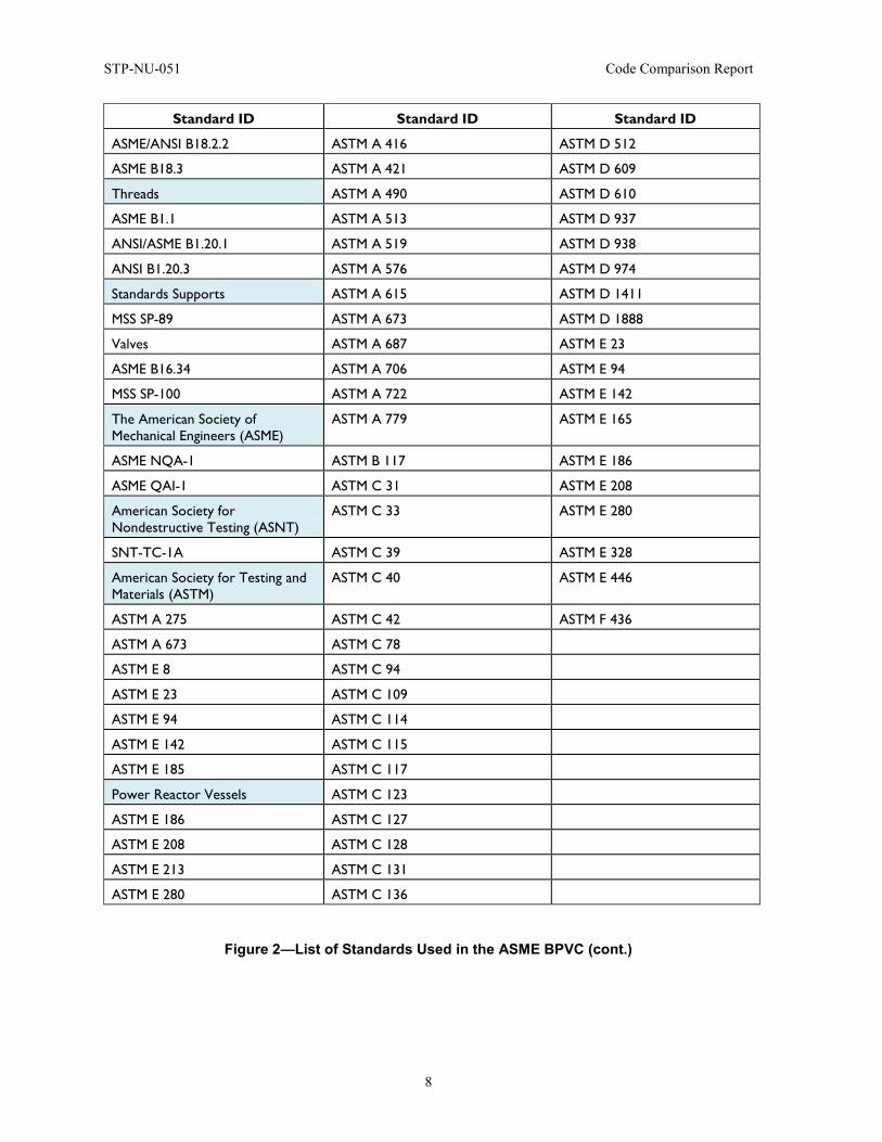
Figure 2—List of Standards Used in the ASME BPVC ......................................................................... 7
Figure 3—AFCEN Organization Chart ................................................................................................ 10
Figure 4—AFCEN Codes..................................................................................................................... 11
Figure 5—List of Standards Used in the RCC-M Code ....................................................................... 12
Figure 6—Organization of JSME Main Committee............................................................................. 16
Figure 7—Organization of JSME Subcommittee on Nuclear Power ................................................... 16
Figure 8—List of Latest JSME Nuclear Codes and Standards............................................................. 17
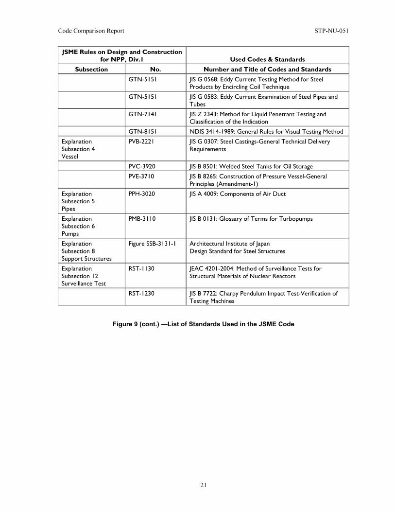
Figure 9—List of Standards Used in the JSME Code .......................................................................... 18
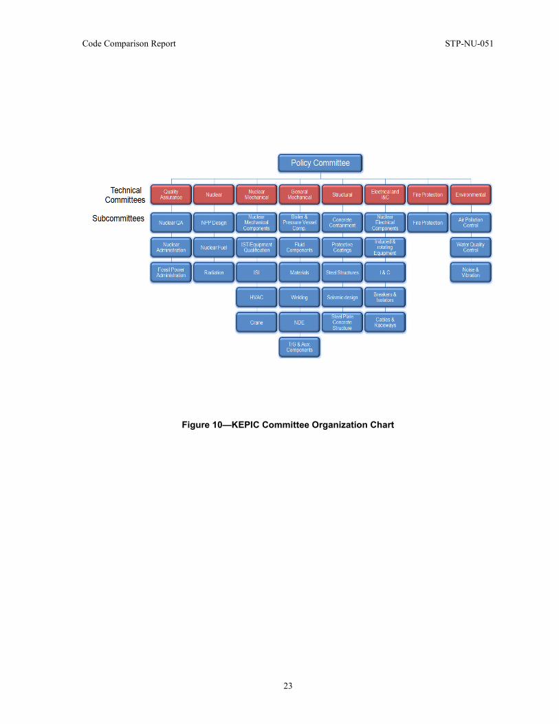
Figure 10—KEPIC Committee Organization Chart ............................................................................. 23
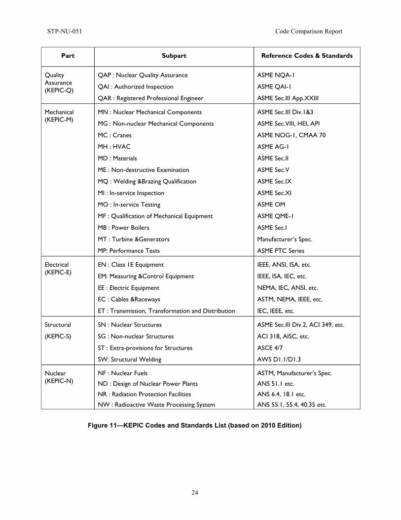
Figure 11—KEPIC Codes and Standards List (based on 2010 Edition) .............................................. 24
Figure 12—KEPIC Endorsement Status by Korea Ministries ............................................................. 25
Figure 13—Governance of the CSA Standards .................................................................................... 29
Figure 14—CSA Standards Development Process .............................................................................. 30
Figure 15—NSSC and TC Organization Chart .................................................................................... 31
Figure 16—List of Standards ............................................................................................................... 32
Figure 17—Comparison ASME and JSME Code Organization .......................................................... 38
Figure 18—Design Stress (Sm), Yield Stength (Sy) and Ultimate Strength (Su) Comparison of Two Carbon Steels, SA-508 Gr 3 Cl2 and 16MND5 (M2111) .......................................... 50
Figure 19—Design Stress (Sm), Yield Stength (Sy), and Ultimate Strength (Su) Comparison of Two Carbon Steels, SA-336 Cl F316LN and Z2CND18-12 (M3301) ............................... 50
Figure 20—Ke vs. Sn/Sm Curves per ASME, RCC-M, JSME and Direct Calculation (Gurdal, PVP 2009) ................................................................................................................................... 61
Figure 21—Filler Material Reference Data Sheet Example for Filler Material Acceptance from RCC-M Section IV S-2800 ................................................................................................ 68
Figure 22—Example of Documentation Sheets to Give for Welding Procedure Specification from ASME Section IX Nonmandatory Appendix B ................................................................. 69
Figure 23—Detailed Section-by-Section Comparison Between ASME BPVC Section III NB Paragraphs and RCC-M Section I B Paragraphs ................................................................ 81
Figure 24—General Comparison Between ASME BPVC Section III NB Paragraphs and RCC-M Section I B Paragraphs ....................................................................................................... 82
Figure 25—General Comparison Between ASME BPVC Section III NB Paragraphs and RCC-M Section I B Paragraphs in Percentages ............................................................................... 82
Figure 26—Comparison of Detailed Requirements for NDE in ASME and JSME Codes .................. 86
Figure 27—Comparison of Ke Factor Used in the Simplified Elastic-Plastic Analysis Between JSME and ASME ............................................................................................................... 88
STP-NU-051 Code Comparison Report
viii
Figure 28—Comparison of ASME NB and JSME Class 1 Rules ........................................................ 93
Figure 29—Comparison of Maximum Allowance Offset in Final Welded Joints Between JSME and ASME ........................................................................................................................... 95
Figure 30—Comparison of Maximum Thickness of Weld Reinforcement Between JSME and ASME ................................................................................................................................. 96
Figure 31—Comparison of Maximum Size of Rounded Indication Between JSME and ASME ....... 97
Figure 32—Detailed Section-by-Section Comparison Between ASME BPVC Section III NB Paragraphs and JSME S-NC1-2008 .................................................................................. 102
Figure 33—General Comparison Between ASME BPVC Section III NB Paragraphs and JSME S-NC1-2008 ........................................................................................................... 103
Figure 34—General Comparison Between ASME BPVC Section III NB Paragraphs and JSME S-NC1-2008 in Percentages ................................................................................... 103
Code Comparison Report STP-NU-051
ix
FOREWORD ASME Standards Technology, LLC (ASME ST-LLC) appreciates the collaborative effort put forth by all those involved in the development of this report. The report is the result of a multi-national effort by Standards Development Organizations (SDOs) from the United States of America, France, Japan, Korea and Canada. We also acknowledge the nuclear regulatory authorities who supported this work, which was initiated with a global vision of codes and standards consistency.
Established in 1880, the American Society of Mechanical Engineers (ASME) is a professional not-for-profit organization with more than 127,000 members promoting the art, science and practice of mechanical and multidisciplinary engineering and allied sciences. ASME develops codes and standards that enhance public safety, and provides lifelong learning and technical exchange opportunities benefiting the engineering and technology community. Visit www.asme.org for more information.
The ASME Standards Technology, LLC (ASME ST-LLC) is a not-for-profit Limited Liability Company, with ASME as the sole member, formed in 2004 to carry out work related to newly commercialized technology. The ASME ST-LLC mission includes meeting the needs of industry and government by providing new standards-related products and services, which advance the application of emerging and newly commercialized science and technology and providing the research and technology development needed to establish and maintain the technical relevance of codes and standards. Visit www.stllc.asme.org for more information.
STP-NU-051 Code Comparison Report
x
ABSTRACT The Multinational Design Evaluation Programme (MDEP) Code Comparison Project was initiated in late 2006 in response to a request by the MDEP Codes and Standards Working Group (CSWG) formerly known as the Working Group on Component Manufacturing Oversight (WGCMO). The CSWG invited the organizations responsible for development of major nuclear component construction codes and standards, Standards Development Organizations (SDOs), to make presentations regarding the requirements of their respective codes and standards pertaining to light water cooled nuclear power plants along with comparisons between those respective codes and standards.
In an effort to facilitate consistent design and manufacturing processes for Nuclear Power Plant Class 1 components among the ten MDEP countries, the CSWG requested the various SDOs to develop a comparison of the requirements of their respective codes and standards and those of the others.
The SDOs from the USA, France, Japan, Korea and Canada (ASME, AFCEN, JSME, KEA, and CSA, respectively) agreed to participate in this code comparison project and develop comparisons of the requirements for Class 1 vessels, piping, pumps and valves.
The objective of this report is to identify and summarize the differences between major international nuclear codes and standards for Class 1 equipment; namely those of AFCEN (RCC-M), ASME (Section III), CSA (N-285), JSME (S NC1) and KEA (KEPIC-MN).
The reader is reminded that each of the codes is a set of consistent rules. The requirements of one area may be, and often are, dependent on the requirements in other sections. Since a line-by-line comparison has been done, it may be tempting to judge the entire code based on the differences between these individual points, but this may not lead to a correct conclusion. This exercise identifies the different requirements of the different codes. It was not within the scope of this report to provide conclusions relative to the full implementation of the various Codes.
Code Comparison Report STP-NU-051
1
1 INTRODUCTION
1.1 Background and Scope The Multinational Design Evaluation Programme (MDEP) Code Comparison Project was initiated in late 2006 in response to a request by the MDEP Codes and Standards Working Group (CSWG) formerly known as the Working Group on Component Manufacturing Oversight (WGCMO). The CSWG invited the organizations responsible for development of major nuclear component construction codes and standards, Standards Development Organizations (SDOs), to make presentations regarding the requirements of their respective codes and standards pertaining to light water cooled nuclear power plants along with comparisons between those respective codes and standards.
In an effort to facilitate consistent design and manufacturing processes among the 10 MDEP countries for Class 1 Nuclear Power Plant components, the CSWG requested the various SDOs to develop a comparison of the requirements of their respective codes and standards and those of the others.
The SDOs from the USA, France, Japan, Korea and Canada (ASME, AFCEN, JSME, KEA, and CSA, respectively) agreed to participate in this code comparison project and develop comparisons of the requirements for Class 1 vessels, piping, pumps and valves. The SDO from Russia (NIKIET) has since also joined in this effort, and is developing comparisons of the NIKIET PNAE-G-7 requirements to those of ASME Section III for Class 1 components.
As the project was initiated, the SDOs determined that development of comparisons between every code and each of the others would be very complicated. Recognizing that the CSA, JSME, KEA and AFCEN Codes were all originally developed based on ASME Section III, the SDOs agreed to define ASME Section III as the baseline for the comparison and compare each of the other Codes to ASME Section III and also to base the comparisons on the 2007 editions of each of the Codes.
1.2 Objectives The objective of this report is to identify and summarize the differences between major international nuclear codes and standards for Class 1 equipment; namely those of AFCEN (RCC-M), ASME (Section III), CSA (N-285), JSME (S NC1) and KEA (KEPIC-MN).
The results of this work are intended for use by regulatory bodies, component designers and component manufacturers.
The reader is reminded that each of the codes is a set of consistent rules. The requirements of one area may be, and often are, dependent on the requirements in other sections. Since a line-by-line comparison has been done, it may be tempting to judge the entire code based on the differences between these individual points; but, this may not lead to a correct conclusion.
This exercise in summarizing the differences between major international nuclear codes and standards for Class 1 equipment identifies the different requirements of the different codes. It was not within the scope of this report to provide conclusions relative to the full implementation of the various Codes.
1.3 Contents of the Report The report is organized into 8 sections. Section 1 provides a general Introduction. The main body of the report begins with Section 2, which provides a general presentation of the background for each code along with a description of the organizations responsible for administering the Codes. A summary list of the standards applied within each respective code is also provided. Section 3 provides a comparison of the general layout for each of the Codes relative to ASME Section III.
STP-NU-051 Code Comparison Report
2
Sections 4 through 7 summarize the individual code comparisons for the AFCEN RCC-M, JSME S NC-1, KEA KEPIC-MN and CSA N-285 Codes, each compared relative to ASME Section III. Section 8 provides the applicable References. The detailed Code Comparisons prepared by each of the respective SDOs are provided in the Appendices.
Sections 4 through 7 are organized in a similar fashion and provide a comparison between the codes consistent with the order of the paragraphs in ASME Section III Division 1. The first subsection after the Introduction compares the NB-1000 preliminary paragraphs from the ASME Boiler & Pressure Vessel Code (BPVC) to their equivalents from the others codes. The second subsection addresses the NB-2000 paragraphs related to materials and the third deals with the NB-3000 paragraphs related to design. The NB-4000 requirements associated with fabrication and installation are discussed in the subsection entitled Fabrication and Welding. Examination requirements from NB-5000 are dealt with in the same subsection. The NB-6000 paragraphs related to testing are partially covered in the Pressure Tests subsection. NB-7000, which deals with overpressure protection, is addressed in the last subsection before a short overview on Quality aspects of the codes and the Conclusion.
The code comparison is organized in three levels. First, in each of the subsections mentioned in the previous paragraph, the structure is very similar: they all start with highlights. These highlights summarize the main warnings that need to be communicated. They represent major differences that exist between the ASME BPVC and the other codes. The second level is the text after these highlights: it develops the ideas given by providing comments and background information but it also lists additional differences between the codes. Finally, the third and more detailed level of comparison can be found in the Appendices: the reader will find detailed tables comparing the ASME Section III Division 1 line by line to the other codes.
Sections 4 thru 7 each include tables that present the general layouts of the codes from the ASME point of view as well as from the perspective of the code being compared to the ASME Code.
1.4 Comparison Scale The following comparison scale is used in this report, specifically in the Appendices:
(a) A1 = Same (b) A2 = Equivalent (c) B1 = Different – Not Specified (d) B2 = Technically Different
These categories of the comparison scale are defined in the following paragraphs.
(a) A1 = Same
Requirements classified as category A1 are considered to be technically identical. Requirements are classified as category A1 and considered to be the same even if there are inconsequential differences in wording, such as might result due to translation from one language to another, as long as the wording does not change the meaning or interpretation of the requirement. Likewise, differences in paragraph numbering are not considered when classifying requirements as long as the same requirement exists in both codes being compared.
(b) A2 = Equivalent
Requirements are considered to be equivalent when applying either code or standard, if compliance with the applied code or standard will also meet the requirements of the other code or standard. Equivalence is not affected by differences in level of precision of unit conversions.
Code Comparison Report STP-NU-051
3
(c) B1 = Different – Not specified
Requirements are considered to be different – not specified, if one code or standard includes requirements that the compared code or standard does not specify. This classification may result because of differences in the scope of equipment covered by a respective code, the scope of industrial practices applied in context of the respective code, differences in regulatory requirements applicable in conjunction with application of a particular code or simply as a result of differences in requirements addressed in one code versus those of another.
(d) B2 = Technically Different
Requirements are considered to be technically different if either code requires something more or less than, or otherwise technically different from, the requirements imposed by the other. These differences might be due to different technical approaches applied by a code or imposition of regulatory requirements within the country from which a code originates.
STP-NU-051 Code Comparison Report
4
2 GENERAL PRESENTATION OF CODES
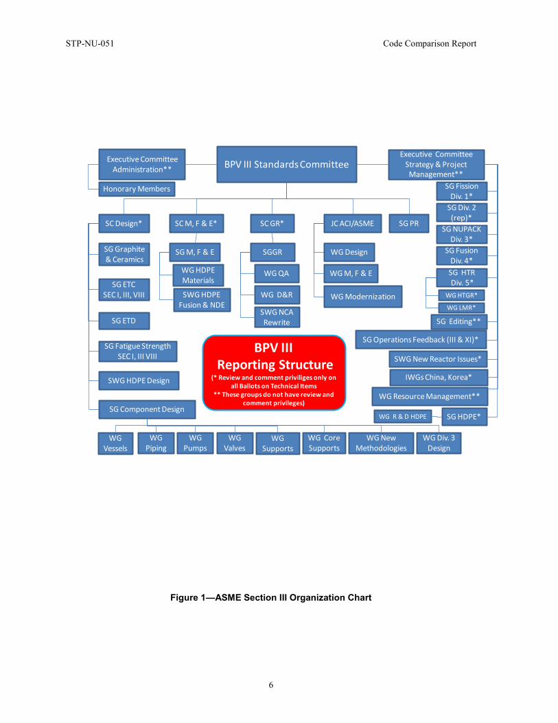
2.1 Background Information on ASME The present ASME Section III organization is provided in Figure 1; a list of the standards used in the ASME BPVC is provided in Figure 2.
In the second half of the 19th century, an important establishment of schools and institutions in engineering was witnessed in the USA. As an example, in 1880 there were no less than 85 engineering colleges throughout the country. At that time, many groups in different fields of engineering were seeking to create organizations of specialized professional standing. The Institution of Chartered Mechanical Engineers had been successfully established in England, 33 years earlier in 1847. In the United States, the American Society of Civil Engineers had been active since 1852, and the American Institute of Mining Engineers had been organized in 1871. But in the USA, for mechanical engineers, none were devoted to machine design, power generation, and industrial processes, to a degree that was capable of projecting a broader national or international role to advance technical knowledge and systematically facilitate a flow of information from research to practical application. Finally, in 1880, the ASME was founded to bridge the gap.
ASME then acted in various domains: it formed its research activities in 1909 and has led in the development of technical standards; for instance, for the screw thread in 1901. But the Society is best known for improving the safety of equipment, especially boilers. From 1870 to 1910, at least 10,000 boiler explosions in North America were recorded. By 1910, the rate jumped to 1300 to 1400 a year. A Boiler Code Committee was formed in 1911 that led to the Boiler Code being published in 1914-15 and was later incorporated in laws of most U.S. states and territories and Canadian provinces.
By 1930, 50 years after ASME was founded, the Society had grown to 20,000 members, though its influence on American workers is far greater. New standards and codes were published in various domains of mechanical engineering to ensure safely designed components. In 1921, the first elevator code was issued; in 1939, standards for turbine generators were laid down.
Today, ASME is a worldwide engineering society with 125,000 members focused on technical, educational and research issues. Its diversity in the mechanical engineering field can be seen in ASME's 36 Technical Divisions (plus one subdivision) and 3 Institutes. Today’s structure of Technical Divisions was established in 1920, when eight were founded: Aerospace, Fuels, Management, Materials, Materials Handling Engineering, Power, Production Engineering and Rail Transportation. Two more were formed the next year: Internal Combustion Engine and Textile Industries. The most recent addition is the Information Storage and Processing Systems Division (June 1996). The organization chart can be seen Figure 1.
Now, focusing more specifically on the nuclear industry, ASME first established in 1956 a committee in charge of writing a new code that would be named the “ASME Boiler and Pressure Vessel Code for Nuclear Age.” A few years later, in 1963, this committee finally proposed to add a new section to the ASME BPVC to cover the rules and good practices to be followed in the newborn civil nuclear industry. This section was Section III and still is the section to refer to in the code for the nuclear industry. Further, the ASME committees that formulate the Sections and Subsections of the Boiler and Pressure Vessel Code are made up of technical experts from many countries and there are no limitations or membership requirements for participation in the committees.
The nuclear sections of the Boiler and Pressure Vessel Code are currently available in English, Korean and Chinese. In addition to the ASME Code for Class 1 components, which is the code discussed in this report and focuses on construction rules for mechanical components of nuclear

Code Comparison Report STP-NU-051
5
reactor pressure boundary, ASME has published multiple other Sections and Subsections for nuclear application:
• Rules for Constructions of Nuclear Facility Components, Subsection NCA – General Requirements for Division 1 and Division 2
• Rules for Construction of Nuclear Facility Components, Division 1 – Class 2 Components
• Rules for Constructions of Nuclear Facility Components, Division 1 – Class 3 Components
• Rules for Construction of Nuclear Facility Components, Division 1 – Class MC Components (Steel Containments)
• Rules for Construction of Nuclear Facility Components, Division 2 – Code for Concrete Containments
• Rules for Construction of Nuclear Facility Components, Division 1 – Supports
• Rules for Construction of Nuclear Facility Components, Division 1 – Core Support Structures
• Rules for Construction of Nuclear Facility Components, Division 1 – Class 1 Components in Elevated Temperature Service
• Rules for In-Service Inspection of Nuclear Power Plant Components.
STP-NU-051 Code Comparison Report
6
Figure 1—ASME Section III Organization Chart
BPV III Standards Committee
SC Design* JC ACI/ASMESC GR*SC M, F & E*
Executive Committee Administration**
Executive Committee Strategy & Project Management**
SG PR
SGGR
WG QA
WG D&R
SG M, F & E
SWG NCA Rewrite
WG Design
WG M, F & E
WG Modernization
SG NUPACK Div. 3*
SG Div. 2 (rep)*
SG Fission Div. 1*
WG Resource Management**
SG HDPE*
SG Operations Feedback (III & XI)*
SG Editing**
SG HTRDiv. 5*
SG Fusion Div. 4*
SG ETD
SG Component Design
SG Fatigue Strength SEC I, III VIII
SG ETC SEC I, III, VIII
SG Graphite & Ceramics
SWG HDPEFusion & NDE
WG HDPEMaterials
SWG HDPE Design
Honorary Members
WG New Methodologies
WG Piping
WG Vessels
WG Pumps
WG Valves
WG Core Supports
WG Supports
WG Div. 3Design
WG LMR*
WG HTGR*
SWG New Reactor Issues*
WG R & D HDPE
BPV IIIReporting Structure
(* Review and comment priviliges only on all Ballots on Technical Items
** These groups do not have review and comment privileges)
IWGs China, Korea*

Code Comparison Report STP-NU-051
7
Standard ID Standard ID Standard ID
Pipes and Tubes Manufacturer’s Standardization Society of the Valve and Fittings Industry (MSS)
American Society for Testing and Materials (ASTM)
ASME B36.10 MSS SP-43 ASTM C 231
ASME B36.19 MSS SP-44 ASTM C 260
Fittings, Flanges and Gaskets MSS SP-87 ASTM C 266
ASME B16.5 U.S. Army Corps of Engineers ASTM C 289
ASME B16.9 CRD-C 36 ASTM C 295
ASME B16.11 CRD-C 39 ASTM C 311
ANSI B16.18 CRD-C 44 ASTM C 342
ASME B16.20 CRD-C 119 ASTM C 441
Wound and Jacketed CRD-C 621 ASTM C 469
ASME B16.21 American Concrete Institute (ACI) ASTM C 494
ASME B16.22 ACI 211.1 ASTM C 496
Fittings ACI 214 ASTM C 512
ASME B16.25 ACI 304R ASTM C 535
ASME B16.28 ACI 305R ASTM C 586
ASME B16.47 ACI 306R ASTM C 595
SAE J513 ACI 309R ASTM C 618
MSS SP-43 ACI 347R ASTM C 637
MSS-SP-44 American Institute of Steel Construction (AISC)
ASTM C 642
MSS SP-87 … ASTM C 937
Piping Applications … ASTM C 939
MSS SP-97 American Public Health Association (APHA)
ASTM C 940
Socket Welding, Threaded and Buttwelding Ends
APHA-4500-5 ASTM C 943
ANSI/AWWA C207 American Society for Nondestructive Testing (ASNT)
ASTM C 953
API 605 SNT-TC-1A & Supplements ASTM C 1017
Bolting American Society for Testing and Materials (ASTM)
ASTM C 1077
ASME B18.2.1 ASTM A 108 ASTM D 92
Figure 2—List of Standards Used in the ASME BPVC
STP-NU-051 Code Comparison Report
8
Standard ID Standard ID Standard ID
ASME/ANSI B18.2.2 ASTM A 416 ASTM D 512
ASME B18.3 ASTM A 421 ASTM D 609
Threads ASTM A 490 ASTM D 610
ASME B1.1 ASTM A 513 ASTM D 937
ANSI/ASME B1.20.1 ASTM A 519 ASTM D 938
ANSI B1.20.3 ASTM A 576 ASTM D 974
Standards Supports ASTM A 615 ASTM D 1411
MSS SP-89 ASTM A 673 ASTM D 1888
Valves ASTM A 687 ASTM E 23
ASME B16.34 ASTM A 706 ASTM E 94
MSS SP-100 ASTM A 722 ASTM E 142
The American Society of Mechanical Engineers (ASME)
ASTM A 779 ASTM E 165
ASME NQA-1 ASTM B 117 ASTM E 186
ASME QAI-1 ASTM C 31 ASTM E 208
American Society for Nondestructive Testing (ASNT)
ASTM C 33 ASTM E 280
SNT-TC-1A ASTM C 39 ASTM E 328
American Society for Testing and Materials (ASTM)
ASTM C 40 ASTM E 446
ASTM A 275 ASTM C 42 ASTM F 436
ASTM A 673 ASTM C 78
ASTM E 8 ASTM C 94
ASTM E 23 ASTM C 109
ASTM E 94 ASTM C 114
ASTM E 142 ASTM C 115
ASTM E 185 ASTM C 117
Power Reactor Vessels ASTM C 123
ASTM E 186 ASTM C 127
ASTM E 208 ASTM C 128
ASTM E 213 ASTM C 131
ASTM E 280 ASTM C 136
Figure 2—List of Standards Used in the ASME BPVC (cont.)
Code Comparison Report STP-NU-051
9
Standard ID Standard ID Standard ID
ASTM E 446 ASTM C 138
ASTM E 606 ASTM C 142
ASTM E 883 ASTM C 143
American Welding Society (AWS) ASTM C 150
AWS A4.2 ASTM C 151
American Welding Society (AWS) ASTM C 157
AWS A4.2 ASTM C 172
AWS A5.1 ASTM C 173
AWS A5.5 ASTM C 183
AWS A5.18 ASTM C 191 Standard Test Method for Time of Setting Hydraulic Cement by Vicat Needle 1999
AWS A5.20 ASTM C 192
AWS A5.28 ASTM C 204
AWS D1.1 ASTM C 227
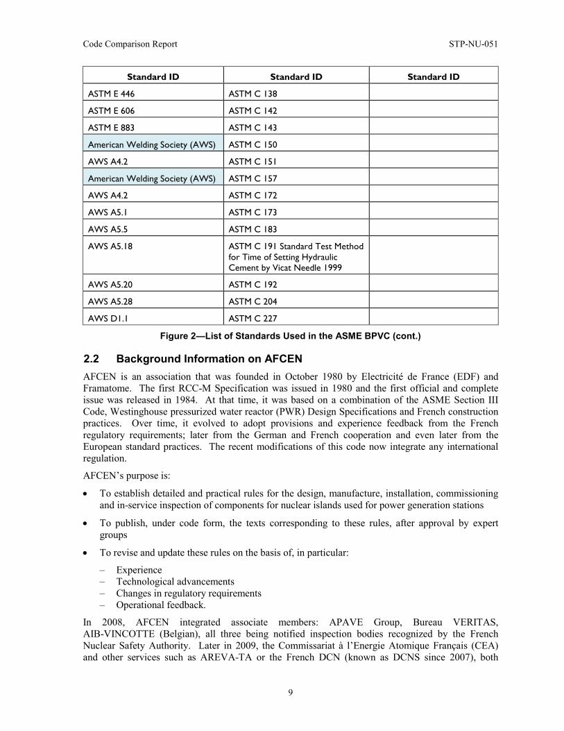
Figure 2—List of Standards Used in the ASME BPVC (cont.)
2.2 Background Information on AFCEN AFCEN is an association that was founded in October 1980 by Electricité de France (EDF) and Framatome. The first RCC-M Specification was issued in 1980 and the first official and complete issue was released in 1984. At that time, it was based on a combination of the ASME Section III Code, Westinghouse pressurized water reactor (PWR) Design Specifications and French construction practices. Over time, it evolved to adopt provisions and experience feedback from the French regulatory requirements; later from the German and French cooperation and even later from the European standard practices. The recent modifications of this code now integrate any international regulation.
AFCEN’s purpose is:
• To establish detailed and practical rules for the design, manufacture, installation, commissioning and in-service inspection of components for nuclear islands used for power generation stations
• To publish, under code form, the texts corresponding to these rules, after approval by expert groups
• To revise and update these rules on the basis of, in particular:
– Experience – Technological advancements – Changes in regulatory requirements – Operational feedback.
In 2008, AFCEN integrated associate members: APAVE Group, Bureau VERITAS, AIB-VINCOTTE (Belgian), all three being notified inspection bodies recognized by the French Nuclear Safety Authority. Later in 2009, the Commissariat à l’Energie Atomique Français (CEA) and other services such as AREVA-TA or the French DCN (known as DCNS since 2007), both

STP-NU-051 Code Comparison Report
10
involved in PWR activities related to nuclear boilers, submarines and ships, were also integrated as associate members of AFCEN.
In 2010, AFCEN expanded membership to allow any nuclear organization to become a member and participate in AFCEN activities.
The AFCEN working methods are similar to ASME Section III working organization, through Board, Committees, Subcommittees, Working Groups, Task Groups, etc., that meet periodically to answer Code Interpretation Sheets and work on Code Modification Sheets in support of modification review/approval and incorporation into addenda or new editions. The AFCEN Organization Chart is provided in Figure 3.
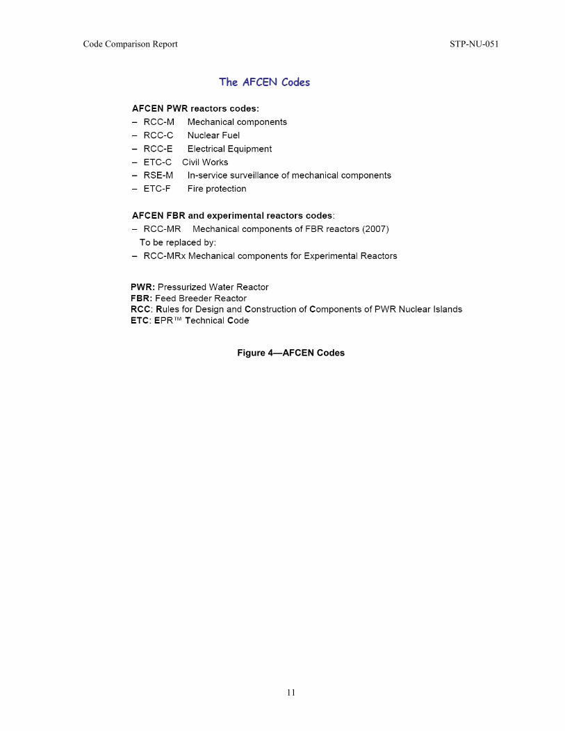
AFCEN publications are currently available in French, English and Chinese. In addition to the RCC-M Code, which is the code discussed here in this report and focuses on Design and Conception Rules for Mechanical Components of PWRs, AFCEN has published multiple other RCC and RSE, which are mentioned in Figure 4.
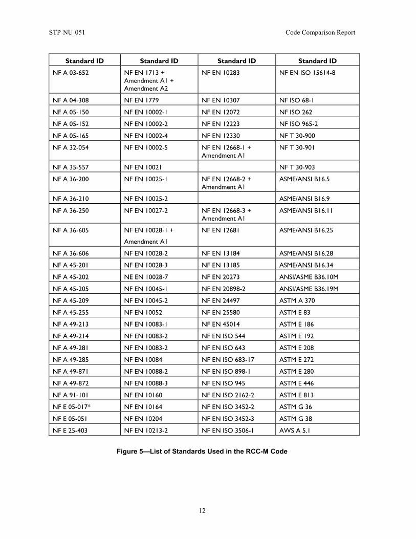
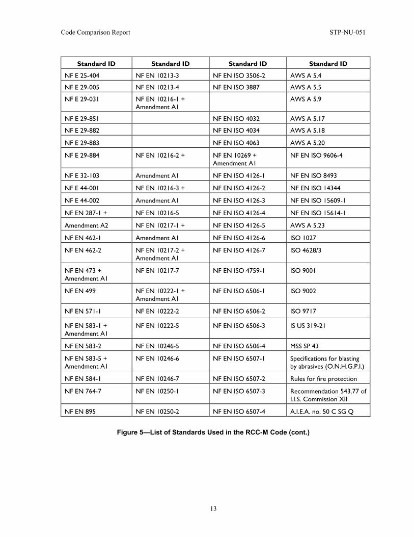
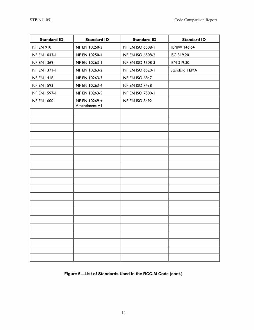
A list of the standards referenced in the RCC-M is provided in Figure 5.
Figure 3—AFCEN Organization Chart
Code Comparison Report STP-NU-051
11
Figure 4—AFCEN Codes
STP-NU-051 Code Comparison Report
12
Standard ID Standard ID Standard ID Standard ID
NF A 03-652 NF EN 1713 + Amendment A1 + Amendment A2
NF EN 10283 NF EN ISO 15614-8
NF A 04-308 NF EN 1779 NF EN 10307 NF ISO 68-1
NF A 05-150 NF EN 10002-1 NF EN 12072 NF ISO 262
NF A 05-152 NF EN 10002-2 NF EN 12223 NF ISO 965-2
NF A 05-165 NF EN 10002-4 NF EN 12330 NF T 30-900
NF A 32-054 NF EN 10002-5 NF EN 12668-1 + Amendment A1
NF T 30-901
NF A 35-557 NF EN 10021 NF T 30-903
NF A 36-200 NF EN 10025-1 NF EN 12668-2 + Amendment A1
ASME/ANSI B16.5
NF A 36-210 NF EN 10025-2 ASME/ANSI B16.9
NF A 36-250 NF EN 10027-2 NF EN 12668-3 + Amendment A1
ASME/ANSI B16.11
NF A 36-605 NF EN 10028-1 +
Amendment A1
NF EN 12681 ASME/ANSI B16.25
NF A 36-606 NF EN 10028-2 NF EN 13184 ASME/ANSI B16.28
NF A 45-201 NF EN 10028-3 NF EN 13185 ASME/ANSI B16.34
NF A 45-202 NE EN 10028-7 NF EN 20273 ANSI/ASME B36.10M
NF A 45-205 NF EN 10045-1 NF EN 20898-2 ANSI/ASME B36.19M
NF A 45-209 NF EN 10045-2 NF EN 24497 ASTM A 370
NF A 45-255 NF EN 10052 NF EN 25580 ASTM E 83
NF A 49-213 NF EN 10083-1 NF EN 45014 ASTM E 186
NF A 49-214 NF EN 10083-2 NF EN ISO 544 ASTM E 192
NF A 49-281 NF EN 10083-2 NF EN ISO 643 ASTM E 208
NF A 49-285 NF EN 10084 NF EN ISO 683-17 ASTM E 272
NF A 49-871 NF EN 10088-2 NF EN ISO 898-1 ASTM E 280
NF A 49-872 NF EN 10088-3 NF EN ISO 945 ASTM E 446
NF A 91-101 NF EN 10160 NF EN ISO 2162-2 ASTM E 813
NF E 05-017* NF EN 10164 NF EN ISO 3452-2 ASTM G 36
NF E 05-051 NF EN 10204 NF EN ISO 3452-3 ASTM G 38
NF E 25-403 NF EN 10213-2 NF EN ISO 3506-1 AWS A 5.1
Figure 5—List of Standards Used in the RCC-M Code
Code Comparison Report STP-NU-051
13
Standard ID Standard ID Standard ID Standard ID
NF E 25-404 NF EN 10213-3 NF EN ISO 3506-2 AWS A 5.4
NF E 29-005 NF EN 10213-4 NF EN ISO 3887 AWS A 5.5
NF E 29-031 NF EN 10216-1 + Amendment A1
AWS A 5.9
NF E 29-851 NF EN ISO 4032 AWS A 5.17
NF E 29-882 NF EN ISO 4034 AWS A 5.18
NF E 29-883 NF EN ISO 4063 AWS A 5.20
NF E 29-884 NF EN 10216-2 + NF EN 10269 + Amendment A1
NF EN ISO 9606-4
NF E 32-103 Amendment A1 NF EN ISO 4126-1 NF EN ISO 8493
NF E 44-001 NF EN 10216-3 + NF EN ISO 4126-2 NF EN ISO 14344
NF E 44-002 Amendment A1 NF EN ISO 4126-3 NF EN ISO 15609-1
NF EN 287-1 + NF EN 10216-5 NF EN ISO 4126-4 NF EN ISO 15614-1
Amendment A2 NF EN 10217-1 + NF EN ISO 4126-5 AWS A 5.23
NF EN 462-1 Amendment A1 NF EN ISO 4126-6 ISO 1027
NF EN 462-2 NF EN 10217-2 + Amendment A1
NF EN ISO 4126-7 ISO 4628/3
NF EN 473 + Amendment A1
NF EN 10217-7 NF EN ISO 4759-1 ISO 9001
NF EN 499 NF EN 10222-1 + Amendment A1
NF EN ISO 6506-1 ISO 9002
NF EN 571-1 NF EN 10222-2 NF EN ISO 6506-2 ISO 9717
NF EN 583-1 + Amendment A1
NF EN 10222-5 NF EN ISO 6506-3 IS US 319-21
NF EN 583-2 NF EN 10246-5 NF EN ISO 6506-4 MSS SP 43
NF EN 583-5 + Amendment A1
NF EN 10246-6 NF EN ISO 6507-1 Specifications for blasting by abrasives (O.N.H.G.P.I.)
NF EN 584-1 NF EN 10246-7 NF EN ISO 6507-2 Rules for fire protection
NF EN 764-7 NF EN 10250-1 NF EN ISO 6507-3 Recommendation 543.77 of I.I.S. Commission XII
NF EN 895 NF EN 10250-2 NF EN ISO 6507-4 A.I.E.A. no. 50 C SG Q
Figure 5—List of Standards Used in the RCC-M Code (cont.)
STP-NU-051 Code Comparison Report
14
Standard ID Standard ID Standard ID Standard ID
NF EN 910 NF EN 10250-3 NF EN ISO 6508-1 IIS/IIW 146.64
NF EN 1043-1 NF EN 10250-4 NF EN ISO 6508-2 ISC 319.20
NF EN 1369 NF EN 10263-1 NF EN ISO 6508-3 ISM 319.30
NF EN 1371-1 NF EN 10263-2 NF EN ISO 6520-1 Standard TEMA
NF EN 1418 NF EN 10263-3 NF EN ISO 6847
NF EN 1593 NF EN 10263-4 NF EN ISO 7438
NF EN 1597-1 NF EN 10263-5 NF EN ISO 7500-1
NF EN 1600 NF EN 10269 + Amendment A1
NF EN ISO 8492
Figure 5—List of Standards Used in the RCC-M Code (cont.)
Code Comparison Report STP-NU-051
15
2.3 Background Information on JSME Historically, detailed technical rules and requirements on the design and construction activities for nuclear power plants in Japan were provided by the government as part of the government regulation system such as MITI Ordinance No. 62 and Notification No. 501. During the period of late 1990s, which was right after the WTO/TBT agreement was in effect in 1994, there evolved discussions that the government regulation should be performance-based and that Standards Development Organization’s (SDO’s) codes and standards should be applied as detailed technical codes (Reference [4]).
The Committee on Power Generation Facility Code was established within the Japan Society of Mechanical Engineers (JSME) in October 1997 to provide technically sound codes and standards to protect people’s safety from industrial hazards and to promote industry development and competitiveness. Behind the scene, a consensus was reached between the regulator and the industry that the regulatory body endorsed and applies SDO codes and standards for their regulation of nuclear power plants in Japan.
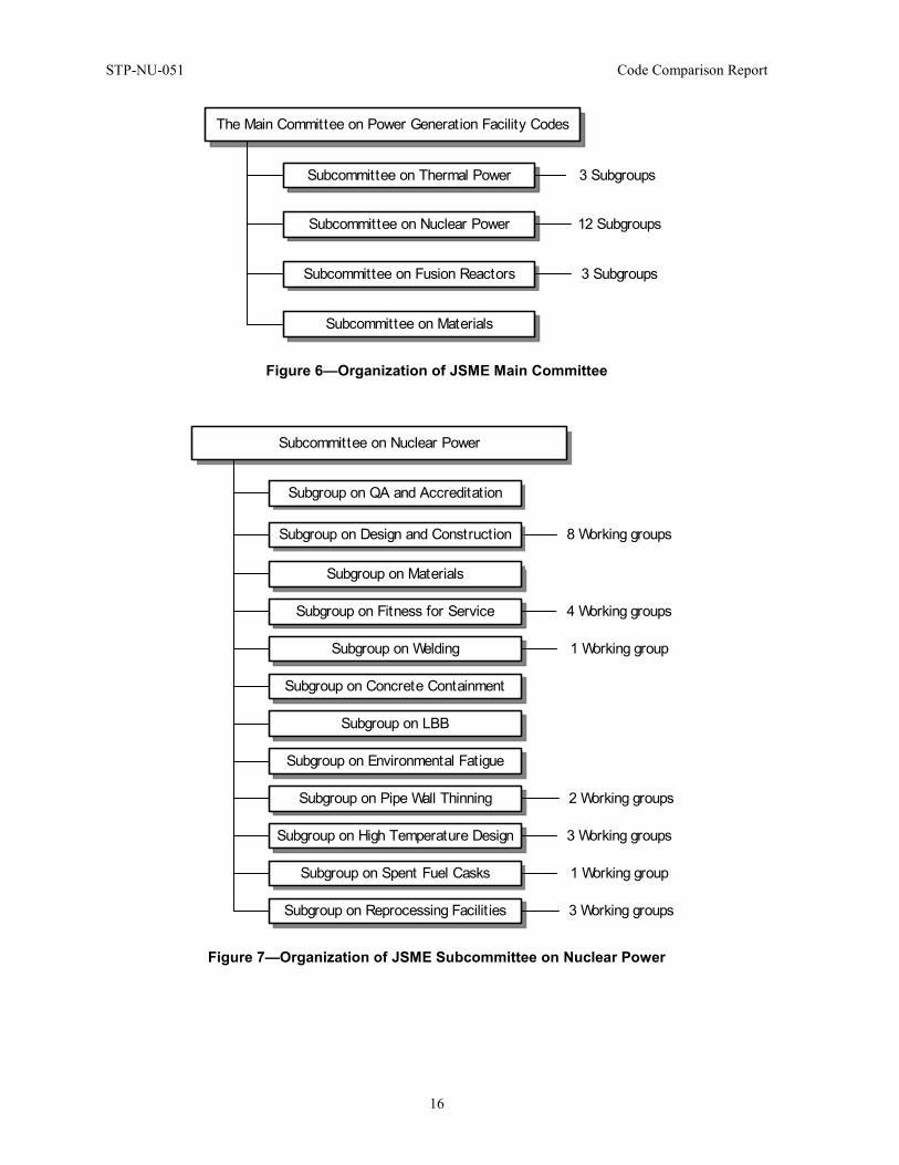
Under the main committee, there are four subcommittees that include thermal power, nuclear power, fusion power and materials, as are shown in Figure 6. The subcommittee on nuclear power is responsible for developing, maintaining and revising JSME nuclear codes and standards, and has in its under-tier 12 subgroups such as design and construction, materials, fitness for service and so on. The organization of the subcommittee on nuclear power is shown in Figure 7. Each of these subgroups is responsible for a code book and many of these subgroups have several working groups.
As of today, total of about 350 volunteers are actively committed to the JSME Codes and standards development and maintenance activities. These volunteers come from various sectors. These include industry (utilities, nuclear systems and component suppliers and steel makers), laboratories and research institutes, university academia, government organizations and regulatory agencies.
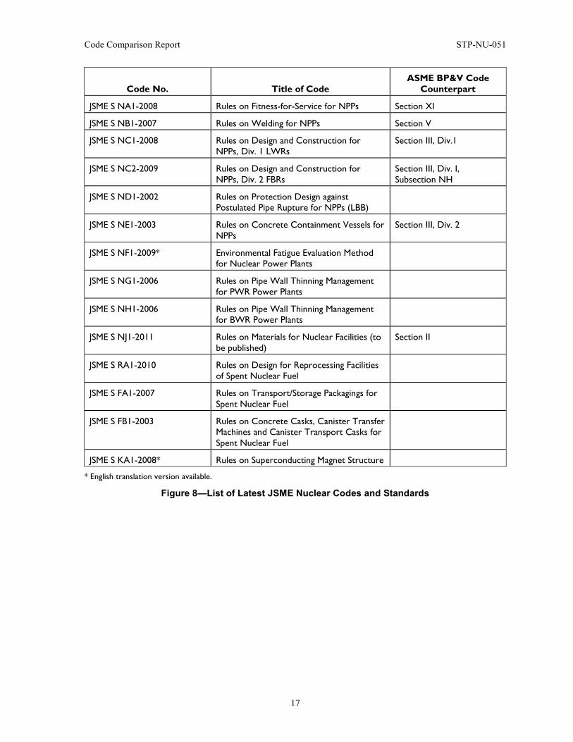
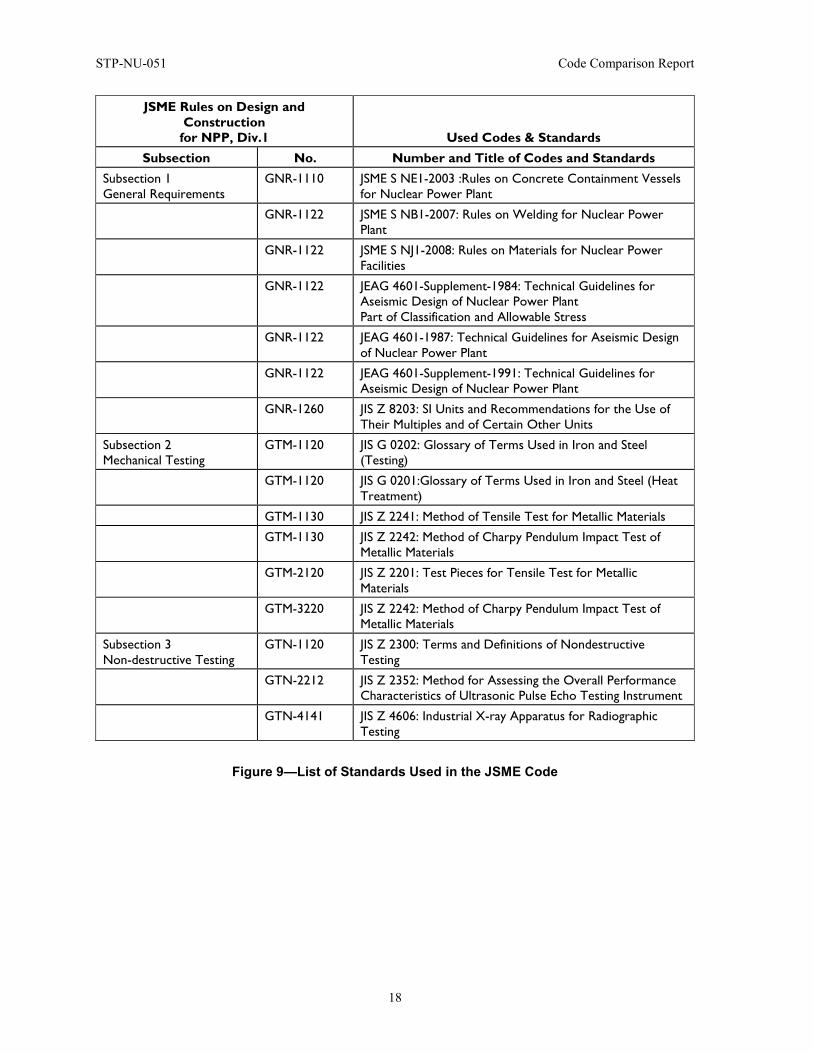
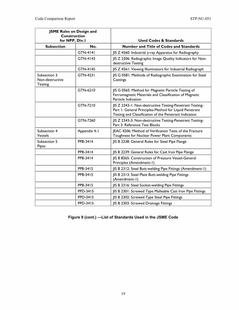
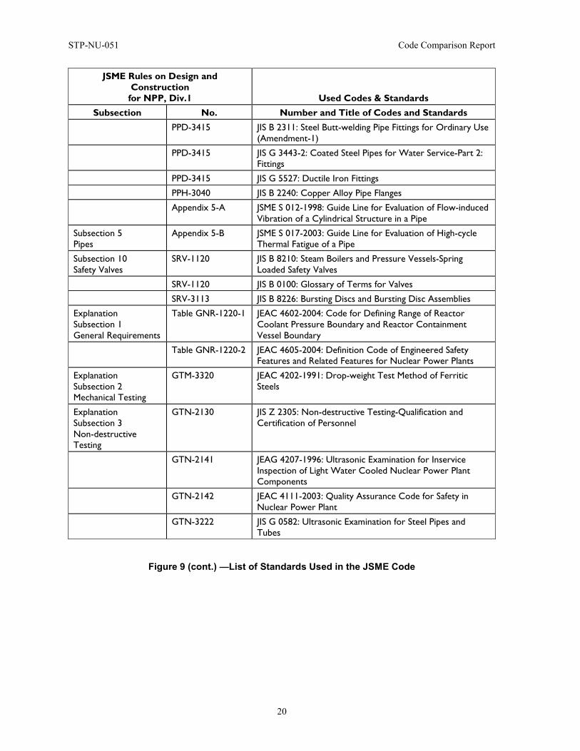
Since its foundation in 1997, the committee has issued a number of codes in the fields of thermal power, nuclear power and fusion power. The latest editions of the JSME nuclear codes are listed in Figure 8 and the standards referenced in the JSME Code are listed in Figure 9. Note that the codes for spent fuel transport/storage casks and for spent fuel reprocessing facilities are included in JSME nuclear codes. Beside these code books, a number of code cases have been issued.
The first nuclear code published by JSME was JSME S NA1-2000, Rules on Fitness-for-Service for NPPs, which was a counterpart of ASME Section XI. The first edition of Rules on Design and Construction for NPPs, which is a counterpart of ASME Section III, was published in 2001. Since then, the JSME nuclear code editions have basically been published in every three to five years. Between these editions addenda have been issued generally on a yearly basis.
As was mentioned earlier, these JSME nuclear codes are subjected to technical evaluation conducted by the Japan Nuclear Energy Organization (JNES)1, and then endorsed by the Nuclear and Industry Safety Agency (NISA).
Among these nuclear codes, JSME S NA1-2008, Rules on Fitness-for-Service for NPPs, JSME S NB1-2007, Rules on Welding for NPPs and JSME S NC1-2007, Rules on Design and Construction for NPPs, Div. 1 LWRs, have been endorsed by NISA, the government regulatory body, and applied to the regulation of LWR nuclear activities of design, construction, maintenance and repair.
1JNES is a Technical Support Organization (TSO) for NISA.
STP-NU-051 Code Comparison Report
16
Figure 6—Organization of JSME Main Committee
Figure 7—Organization of JSME Subcommittee on Nuclear Power
The Main Committee on Power Generation Facility Codes
Subcommittee on Thermal Power
Subcommittee on Nuclear Power
Subcommittee on Fusion Reactors
Subcommittee on Materials
3 Subgroups
3 Subgroups
12 Subgroups
Subcommittee on Nuclear Power
Subgroup on Materials
Subgroup on Fitness for Service
8 Working groups
Subgroup on Welding
Subgroup on Concrete Containment
Subgroup on Design and Construction
Subgroup on LBB
Subgroup on Environmental Fatigue
Subgroup on Pipe Wall Thinning
Subgroup on High Temperature Design
Subgroup on Spent Fuel Casks
Subgroup on Reprocessing Facilit ies
4 Working groups
1 Working group
2 Working groups
3 Working groups
1 Working group
3 Working groups
Subgroup on QA and Accreditation
Code Comparison Report STP-NU-051
17
Code No. Title of Code ASME BP&V Code
Counterpart
JSME S NA1-2008 Rules on Fitness-for-Service for NPPs Section XI
JSME S NB1-2007 Rules on Welding for NPPs Section V
JSME S NC1-2008 Rules on Design and Construction for NPPs, Div. 1 LWRs
Section III, Div.1
JSME S NC2-2009 Rules on Design and Construction for NPPs, Div. 2 FBRs
Section III, Div. I, Subsection NH
JSME S ND1-2002 Rules on Protection Design against Postulated Pipe Rupture for NPPs (LBB)
JSME S NE1-2003 Rules on Concrete Containment Vessels for NPPs
Section III, Div. 2
JSME S NF1-2009* Environmental Fatigue Evaluation Method for Nuclear Power Plants
JSME S NG1-2006 Rules on Pipe Wall Thinning Management for PWR Power Plants
JSME S NH1-2006 Rules on Pipe Wall Thinning Management for BWR Power Plants
JSME S NJ1-2011 Rules on Materials for Nuclear Facilities (to be published)
Section II
JSME S RA1-2010 Rules on Design for Reprocessing Facilities of Spent Nuclear Fuel
JSME S FA1-2007 Rules on Transport/Storage Packagings for Spent Nuclear Fuel
JSME S FB1-2003 Rules on Concrete Casks, Canister Transfer Machines and Canister Transport Casks for Spent Nuclear Fuel
JSME S KA1-2008* Rules on Superconducting Magnet Structure
* English translation version available.
Figure 8—List of Latest JSME Nuclear Codes and Standards
STP-NU-051 Code Comparison Report
18
JSME Rules on Design and Construction
for NPP, Div.1 Used Codes & Standards Subsection No. Number and Title of Codes and Standards
Subsection 1 General Requirements
GNR-1110 JSME S NE1-2003 :Rules on Concrete Containment Vessels for Nuclear Power Plant
GNR-1122 JSME S NB1-2007: Rules on Welding for Nuclear Power Plant
GNR-1122 JSME S NJ1-2008: Rules on Materials for Nuclear Power Facilities
GNR-1122 JEAG 4601-Supplement-1984: Technical Guidelines for Aseismic Design of Nuclear Power Plant Part of Classification and Allowable Stress
GNR-1122 JEAG 4601-1987: Technical Guidelines for Aseismic Design of Nuclear Power Plant
GNR-1122 JEAG 4601-Supplement-1991: Technical Guidelines for Aseismic Design of Nuclear Power Plant
GNR-1260 JIS Z 8203: SI Units and Recommendations for the Use of Their Multiples and of Certain Other Units
Subsection 2 Mechanical Testing
GTM-1120 JIS G 0202: Glossary of Terms Used in Iron and Steel (Testing)
GTM-1120 JIS G 0201:Glossary of Terms Used in Iron and Steel (Heat Treatment)
GTM-1130 JIS Z 2241: Method of Tensile Test for Metallic Materials
GTM-1130 JIS Z 2242: Method of Charpy Pendulum Impact Test of Metallic Materials
GTM-2120 JIS Z 2201: Test Pieces for Tensile Test for Metallic Materials
GTM-3220 JIS Z 2242: Method of Charpy Pendulum Impact Test of Metallic Materials
Subsection 3 Non-destructive Testing
GTN-1120 JIS Z 2300: Terms and Definitions of Nondestructive Testing
GTN-2212 JIS Z 2352: Method for Assessing the Overall Performance Characteristics of Ultrasonic Pulse Echo Testing Instrument
GTN-4141 JIS Z 4606: Industrial X-ray Apparatus for Radiographic Testing
Figure 9—List of Standards Used in the JSME Code
Code Comparison Report STP-NU-051
19
JSME Rules on Design and Construction
for NPP, Div.1 Used Codes & Standards Subsection No. Number and Title of Codes and Standards
GTN-4141 JIS Z 4560: Industrial γ-ray Apparatus for Radiography
GTN-4143 JIS Z 2306: Radiographic Image Quality Indicators for Non-destructive Testing
GTN-4145 JIS Z 4561: Viewing Illuminators for Industrial Radiograph
Subsection 3 Non-destructive Testing
GTN-4231 JIS G 0581: Methods of Radiographic Examination for Steel Castings
GTN-6210 JIS G 0565: Method for Magnetic Particle Testing of Ferromagnetic Materials and Classification of Magnetic Particle Indication
GTN-7210 JIS Z 2343-1: Non-destructive Testing-Penetrant Testing-Part 1: General Principles-Method for Liquid Penetrant Testing and Classification of the Penetrant Indication
GTN-7260 JIS Z 2343-3: Non-destructive Testing-Penetrant Testing-Part 3: Reference Test Blocks
Subsection 4 Vessels
Appendix 4-1 JEAC 4206: Method of Verification Tests of the Fracture Toughness for Nuclear Power Plant Components
Subsection 5 Pipes
PPB-3414 JIS B 2238: General Rules for Steel Pipe Flange
PPB-3414 JIS B 2239: General Rules for Cast Iron Pipe Flange
PPB-3414 JIS B 8265: Construction of Pressure Vessel-General Principles (Amendment-1)
PPB-3415 JIS B 2312: Steel Butt-welding Pipe Fittings (Amendment-1)
PPB-3415 JIS B 2313: Steel Plate Butt-welding Pipe Fittings (Amendment-1)
PPB-3415 JIS B 2316: Steel Socket-welding Pipe Fittings
PPD-3415 JIS B 2301: Screwed Type Malleable Cast Iron Pipe Fittings
PPD-3415 JIS B 2302: Screwed Type Steel Pipe Fittings
PPD-3415 JIS B 2303: Screwed Drainage Fittings
Figure 9 (cont.) —List of Standards Used in the JSME Code
STP-NU-051 Code Comparison Report
20
JSME Rules on Design and Construction
for NPP, Div.1 Used Codes & Standards Subsection No. Number and Title of Codes and Standards
PPD-3415 JIS B 2311: Steel Butt-welding Pipe Fittings for Ordinary Use (Amendment-1)
PPD-3415 JIS G 3443-2: Coated Steel Pipes for Water Service-Part 2: Fittings
PPD-3415 JIS G 5527: Ductile Iron Fittings
PPH-3040 JIS B 2240: Copper Alloy Pipe Flanges
Appendix 5-A JSME S 012-1998: Guide Line for Evaluation of Flow-induced Vibration of a Cylindrical Structure in a Pipe
Subsection 5 Pipes
Appendix 5-B JSME S 017-2003: Guide Line for Evaluation of High-cycle Thermal Fatigue of a Pipe
Subsection 10 Safety Valves
SRV-1120 JIS B 8210: Steam Boilers and Pressure Vessels-Spring Loaded Safety Valves
SRV-1120 JIS B 0100: Glossary of Terms for Valves
SRV-3113 JIS B 8226: Bursting Discs and Bursting Disc Assemblies
Explanation Subsection 1 General Requirements
Table GNR-1220-1 JEAC 4602-2004: Code for Defining Range of Reactor Coolant Pressure Boundary and Reactor Containment Vessel Boundary
Table GNR-1220-2 JEAC 4605-2004: Definition Code of Engineered Safety Features and Related Features for Nuclear Power Plants
Explanation Subsection 2 Mechanical Testing
GTM-3320 JEAC 4202-1991: Drop-weight Test Method of Ferritic Steels
Explanation Subsection 3 Non-destructive Testing
GTN-2130 JIS Z 2305: Non-destructive Testing-Qualification and Certification of Personnel
GTN-2141 JEAG 4207-1996: Ultrasonic Examination for Inservice Inspection of Light Water Cooled Nuclear Power Plant Components
GTN-2142 JEAC 4111-2003: Quality Assurance Code for Safety in Nuclear Power Plant
GTN-3222 JIS G 0582: Ultrasonic Examination for Steel Pipes and Tubes
Figure 9 (cont.) —List of Standards Used in the JSME Code
Code Comparison Report STP-NU-051
21
JSME Rules on Design and Construction for NPP, Div.1 Used Codes & Standards
Subsection No. Number and Title of Codes and Standards GTN-5151 JIS G 0568: Eddy Current Testing Method for Steel
Products by Encircling Coil Technique
GTN-5151 JIS G 0583: Eddy Current Examination of Steel Pipes and Tubes
GTN-7141 JIS Z 2343: Method for Liquid Penetrant Testing and Classification of the Indication
GTN-8151 NDIS 3414-1989: General Rules for Visual Testing Method
Explanation Subsection 4 Vessel
PVB-2221 JIS G 0307: Steel Castings-General Technical Delivery Requirements
PVC-3920 JIS B 8501: Welded Steel Tanks for Oil Storage
PVE-3710 JIS B 8265: Construction of Pressure Vessel-General Principles (Amendment-1)
Explanation Subsection 5 Pipes
PPH-3020 JIS A 4009: Components of Air Duct
Explanation Subsection 6 Pumps
PMB-3110 JIS B 0131: Glossary of Terms for Turbopumps
Explanation Subsection 8 Support Structures
Figure SSB-3131-1 Architectural Institute of Japan Design Standard for Steel Structures
Explanation Subsection 12 Surveillance Test
RST-1130 JEAC 4201-2004: Method of Surveillance Tests for Structural Materials of Nuclear Reactors
RST-1230 JIS B 7722: Charpy Pendulum Impact Test-Verification of Testing Machines
Figure 9 (cont.) —List of Standards Used in the JSME Code
STP-NU-051 Code Comparison Report
22
2.4 Background Information on KEA The Korea Electric Association is the sole organization in Korea that maintains and develops the technical standards in the power industry field. In 2001, KEA was registered as a private collective standards development organization at the ISO/IEC information center. The association pursues improved domestic technical power in Korea’s power industry, continuously reflects power plant construction and operation experience and advances the standardization technology by continuously maintaining and managing KEPIC.
KEPIC is an organization standard that was developed by industry bodies with the support of the government to secure the stability/reliability and quality of electric power industry facilities and equipment. It is the industry technology standard that comprehensively provides the technological guidelines for the overall stages from design, fabrication and installation to construction, testing, inspections, operation, etc.
KEPIC was developed by the KEPCO since 1992, after the feasibility study of 1987 as part of the government’s policy of self-reliant nuclear power technology, and the related works have been transferred to the nonprofit organization, the Korea Electric Association, in accordance with government policy of 1995. KEPIC committees were formed and KEPIC 1995 edition was issued in the same year.
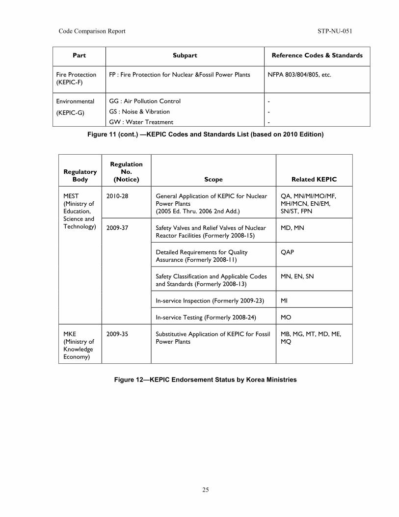
The KEPIC Technical Committee has been expanded and reorganized many times to form the current organization (Figure 10) with one Policy Committee, 8 Technical committees and 33 subcommittees, and approximately 400 specialists in related fields are now working, including the Regulatory Agency, Utilities, Industries, Academies, Research Institutes, Authorized Inspection Agencies, etc. Originally, KEPIC was developed with a focus on the standards of nuclear power safety as related with pressurized light water reactors. However, it has been expanded through the 2000 edition, 2005 edition and 2010 edition (338 types). Currently, as shown in Figure 11, standards related with nuclear and thermal power generation have been maintained and developed by each technical field.
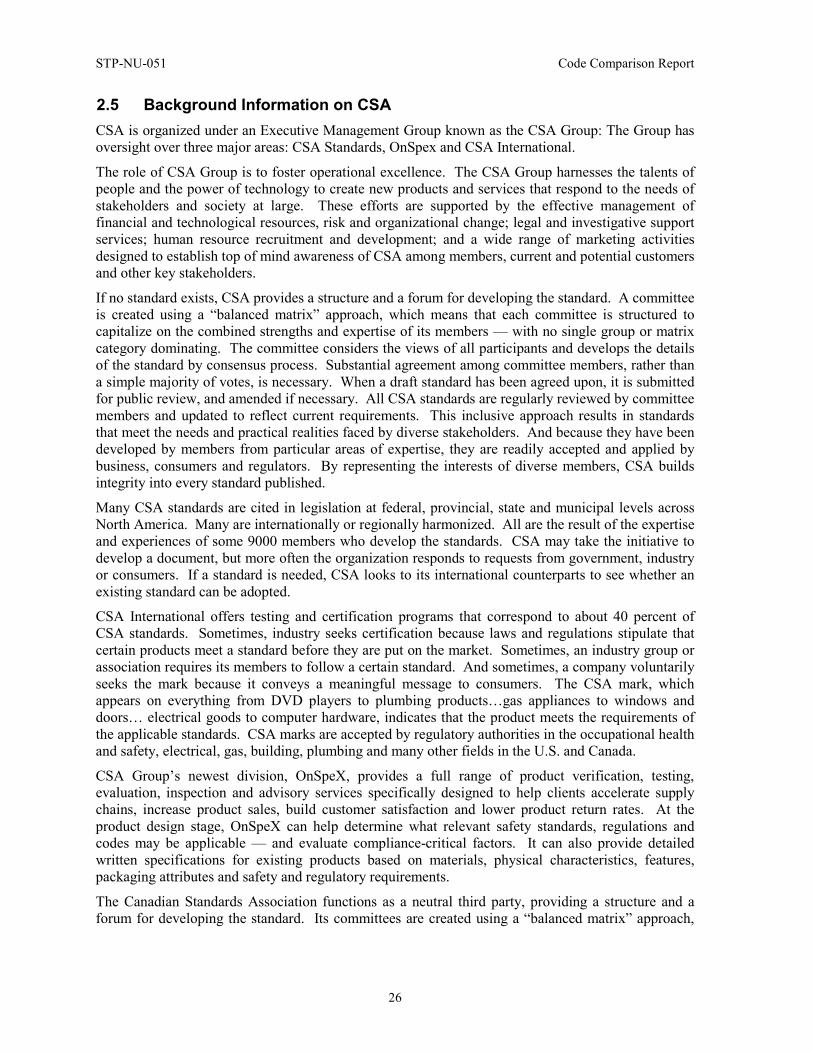
KEPIC has been endorsed with the application of nuclear power plants in Korea through the government’s public announcement, as shown in Figure 12, since the 1995 edition. To note, in July 2010, KEPIC was endorsed by the UAE regulatory organization (FANR), for the application codes for nuclear power plants constructed in the UAE.
Code Comparison Report STP-NU-051
23
Figure 10—KEPIC Committee Organization Chart
STP-NU-051 Code Comparison Report
24
Part Subpart Reference Codes & Standards
Quality Assurance (KEPIC-Q)
QAP : Nuclear Quality Assurance
QAI : Authorized Inspection
QAR : Registered Professional Engineer
ASME NQA-1
ASME QAI-1
ASME Sec.III App.XXIII
Mechanical (KEPIC-M)
MN : Nuclear Mechanical Components
MG : Non-nuclear Mechanical Components
MC : Cranes
MH : HVAC
MD : Materials
ME : Non-destructive Examination
MQ : Welding &Brazing Qualification
MI : In-service Inspection
MO : In-service Testing
MF : Qualification of Mechanical Equipment
MB : Power Boilers
MT : Turbine &Generators
MP: Performance Tests
ASME Sec.III Div.1&3
ASME Sec.VIII, HEI, API
ASME NOG-1, CMAA 70
ASME AG-1
ASME Sec.II
ASME Sec.V
ASME Sec.IX
ASME Sec.XI
ASME OM
ASME QME-1
ASME Sec.I
Manufacturer’s Spec.
ASME PTC Series
Electrical (KEPIC-E)
EN : Class 1E Equipment
EM: Measuring &Control Equipment
EE : Electric Equipment
EC : Cables &Raceways
ET : Transmission, Transformation and Distribution
IEEE, ANSI, ISA, etc.
IEEE, ISA, IEC, etc.
NEMA, IEC, ANSI, etc.
ASTM, NEMA, IEEE, etc.
IEC, IEEE, etc.
Structural
(KEPIC-S)
SN : Nuclear Structures
SG : Non-nuclear Structures
ST : Extra-provisions for Structures
SW: Structural Welding
ASME Sec.III Div.2, ACI 349, etc.
ACI 318, AISC, etc.
ASCE 4/7
AWS D1.1/D1.3
Nuclear (KEPIC-N)
NF : Nuclear Fuels
ND : Design of Nuclear Power Plants
NR : Radiation Protection Facilities
NW : Radioactive Waste Processing System
ASTM, Manufacturer’s Spec.
ANS 51.1 etc.
ANS 6.4, 18.1 etc.
ANS 55.1, 55.4, 40.35 etc.
Figure 11—KEPIC Codes and Standards List (based on 2010 Edition)
Code Comparison Report STP-NU-051
25
Part Subpart Reference Codes & Standards
Fire Protection (KEPIC-F)
FP : Fire Protection for Nuclear &Fossil Power Plants NFPA 803/804/805, etc.
Environmental
(KEPIC-G)
GG : Air Pollution Control
GS : Noise & Vibration
GW : Water Treatment
-
-
-
Figure 11 (cont.) —KEPIC Codes and Standards List (based on 2010 Edition)
Regulatory Body
Regulation No.
(Notice) Scope Related KEPIC
MEST (Ministry of Education, Science and Technology)
2010-28 General Application of KEPIC for Nuclear Power Plants (2005 Ed. Thru. 2006 2nd Add.)
QA, MN/MI/MO/MF, MH/MCN, EN/EM, SN/ST, FPN
2009-37 Safety Valves and Relief Valves of Nuclear Reactor Facilities (Formerly 2008-15)
MD, MN
Detailed Requirements for Quality Assurance (Formerly 2008-11)
QAP
Safety Classification and Applicable Codes and Standards (Formerly 2008-13)
MN, EN, SN
In-service Inspection (Formerly 2009-23) MI
In-service Testing (Formerly 2008-24) MO
MKE (Ministry of Knowledge Economy)
2009-35 Substitutive Application of KEPIC for Fossil Power Plants
MB, MG, MT, MD, ME, MQ
Figure 12—KEPIC Endorsement Status by Korea Ministries
STP-NU-051 Code Comparison Report
26
2.5 Background Information on CSA CSA is organized under an Executive Management Group known as the CSA Group: The Group has oversight over three major areas: CSA Standards, OnSpex and CSA International.
The role of CSA Group is to foster operational excellence. The CSA Group harnesses the talents of people and the power of technology to create new products and services that respond to the needs of stakeholders and society at large. These efforts are supported by the effective management of financial and technological resources, risk and organizational change; legal and investigative support services; human resource recruitment and development; and a wide range of marketing activities designed to establish top of mind awareness of CSA among members, current and potential customers and other key stakeholders.
If no standard exists, CSA provides a structure and a forum for developing the standard. A committee is created using a “balanced matrix” approach, which means that each committee is structured to capitalize on the combined strengths and expertise of its members — with no single group or matrix category dominating. The committee considers the views of all participants and develops the details of the standard by consensus process. Substantial agreement among committee members, rather than a simple majority of votes, is necessary. When a draft standard has been agreed upon, it is submitted for public review, and amended if necessary. All CSA standards are regularly reviewed by committee members and updated to reflect current requirements. This inclusive approach results in standards that meet the needs and practical realities faced by diverse stakeholders. And because they have been developed by members from particular areas of expertise, they are readily accepted and applied by business, consumers and regulators. By representing the interests of diverse members, CSA builds integrity into every standard published.
Many CSA standards are cited in legislation at federal, provincial, state and municipal levels across North America. Many are internationally or regionally harmonized. All are the result of the expertise and experiences of some 9000 members who develop the standards. CSA may take the initiative to develop a document, but more often the organization responds to requests from government, industry or consumers. If a standard is needed, CSA looks to its international counterparts to see whether an existing standard can be adopted.
CSA International offers testing and certification programs that correspond to about 40 percent of CSA standards. Sometimes, industry seeks certification because laws and regulations stipulate that certain products meet a standard before they are put on the market. Sometimes, an industry group or association requires its members to follow a certain standard. And sometimes, a company voluntarily seeks the mark because it conveys a meaningful message to consumers. The CSA mark, which appears on everything from DVD players to plumbing products…gas appliances to windows and doors… electrical goods to computer hardware, indicates that the product meets the requirements of the applicable standards. CSA marks are accepted by regulatory authorities in the occupational health and safety, electrical, gas, building, plumbing and many other fields in the U.S. and Canada.
CSA Group’s newest division, OnSpeX, provides a full range of product verification, testing, evaluation, inspection and advisory services specifically designed to help clients accelerate supply chains, increase product sales, build customer satisfaction and lower product return rates. At the product design stage, OnSpeX can help determine what relevant safety standards, regulations and codes may be applicable — and evaluate compliance-critical factors. It can also provide detailed written specifications for existing products based on materials, physical characteristics, features, packaging attributes and safety and regulatory requirements.
The Canadian Standards Association functions as a neutral third party, providing a structure and a forum for developing the standard. Its committees are created using a “balanced matrix” approach,
Code Comparison Report STP-NU-051
27
which means that each committee is structured to capitalize on the combined strengths and expertise of its members — with no single group dominating.
The committee considers the views of all participants and develops the details of the standard by a consensus process, which includes the principles of inclusive participation, and respect for diverse interest and transparency. Substantial agreement among committee members, rather than a simple majority of votes, is necessary. When a draft standard has been agreed upon, it is submitted for public review, and amended if necessary.
The committee’s standards are living documents, continually revised and refreshed to address changing requirements and emerging technologies. Each standard is reviewed at least every five years as part of the process of continual improvement.
The governance of the CSA Standards development process is depicted Figure 13.
The standards development process under which CSA and other Standards Development Organizations operate is well developed and formally documented and controlled. This process includes eight distinct stages:
• Preliminary Stage: On receipt of a request for the development of a standard, an evaluation is conducted and the project is submitted for authorization.
• Proposal Stage: Public notice of intent to proceed is published and a Technical Committee is formed — or the project is assigned to an existing Technical Committee.
• Preparatory Stage: A working draft is prepared and a project schedule is established.
• Committee Stage: The Technical Committee or Technical Subcommittee — facilitated by CSA staff — develops the draft through an iterative process that typically involves a number of committee meetings.
• Enquiry Stage: The draft is offered to the public for review and comment, the Technical Committee reaches consensus, CSA staff conduct a quality review and a pre-approval edit is completed.
• Approval Stage: The Technical Committee approves the technical content by letter ballot or recorded vote. A second-level review verifies that standards development procedures were followed.
• Publication Stage: CSA staff conducts a final edit to verify conformity with the applicable editorial and procedural requirements and then publishes and disseminates the standard.
• Maintenance Stage: The standard is maintained with the objective of keeping it up to date and technically valid. This may include the publication of amendments, the interpretation of a standard or clause and the systematic (five-year) review of all standards.
Figure 14 delineates the Standards development flow from the initial request to final publication and its ongoing maintenance.
The CSA Nuclear Standards Program promotes safe and reliable nuclear power industry in Canada and has a positive influence on the international nuclear power industry. While focusing on nuclear power plants, the program area provides guidance for other types of nuclear facilities for selected topics, such as radioactive waste management and environmental releases.
Specifically, the program is designed to:
• Address industry knowledge management challenges by embedding key historical knowledge in documents and exposing young technical personnel to seasoned experts.
STP-NU-051 Code Comparison Report
28
• Provide an alternative to Regulatory Documents with consistent guidance to the industry.
• Provide a structure for interpretations of Standards by an “expert panel.”
• Meet identified stakeholder needs for Standards on which to base future work.
• Provide standards and forums to support licensing and regulation.
Users of the Nuclear Standard are reminded that the design, fabrication, installation, commissioning and operation of nuclear facilities in Canada are subject to the provisions of the Act and its Regulations. The Canadian Nuclear Safety Commission (CNSC) specifies regulatory and administrative requirements for pressure-retaining systems in their Regulations and regulatory documents. Where CNSC documents conflict with the requirements of this Standard, the CNSC documents take precedence. In this Standard, the CNSC is referred to as the regulatory authority.
The CSA Nuclear Strategic Steering Committee (NSSC) consists largely of senior executives and managers from the industry and regulators; it operates under the auspices of the CSA and its Board of Directors and Standards Policy Board. The NSSC’s primary role is to set the long-term strategic direction for Canadian nuclear standards, and to provide guidance and support to the TC structure.
There are 10 TCs reporting to the NSSC, each covering distinct functional areas. Each TC is headed by a chair and consists of technical experts drawn from across the industry and relevant public interest groups. The TCs generate standards in the areas seen in Figure 15.
The various standards used can be found Figure 16.
The CSA N285 series consists of the following Standards:
• CSA N285.0 – General requirements for pressure-retaining systems and components in CANDU nuclear power plants.
• CAN/CSA-N285.1 – This Standard no longer exists as a separate publication; it was incorporated into CAN/CSA-N285.0-95.
• CAN/CSA-N285.2 – This Standard no longer exists as a separate publication; it is incorporated as Annex I of CSA N285.0-08.
• CAN/CSA-N285.3 – This Standard no longer exists as a separate publication; it is incorporated as Annex J of CSA N285.0-08.
• CSA N285.4 – Periodic inspection of CANDU nuclear power plant components.
• CAN/CSA-N285.5 – Periodic Inspection of CANDU Nuclear Power Plant Containment Components.
• CSA N285.6 Series – Material Standards for reactor components for CANDU nuclear power plants (published with CSA N285.0).
• CSA N285.8 – Technical requirements for in-service evaluation of zirconium alloy pressure tubes in CANDU reactors.
The first edition of CSA Standard CAN3-N285.0, General Requirements for Pressure-Retaining Systems and Components in CANDU Nuclear Power Plants, was issued in March 1981, which superseded the preliminary Standard N285.1 developed in the mid-1970s.
The second edition CSA Standard CAN/CSA-N285.0, General Requirements for Pressure-Retaining Systems and Components in CANDU Nuclear Power Plants, supersedes the edition published in March 1981 and its amendments.
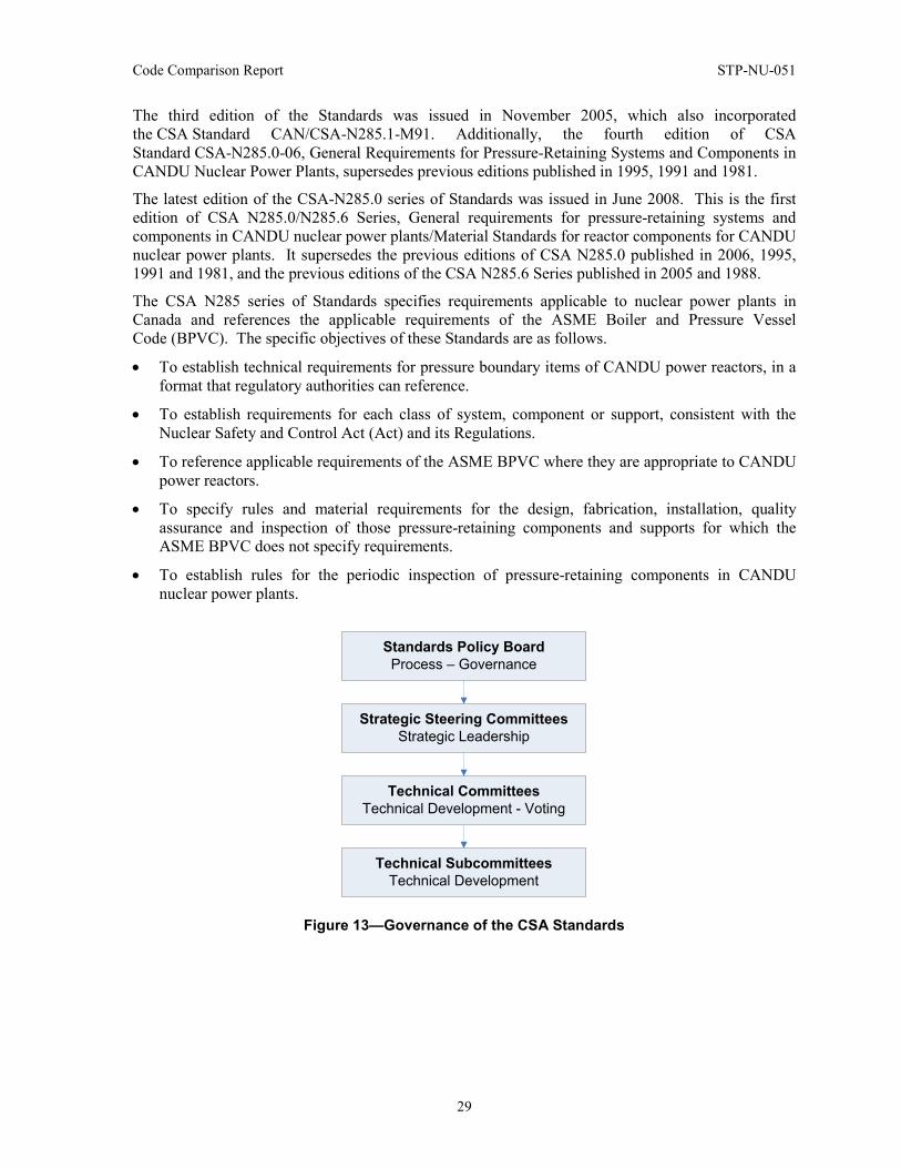
Code Comparison Report STP-NU-051
29
The third edition of the Standards was issued in November 2005, which also incorporated the CSA Standard CAN/CSA-N285.1-M91. Additionally, the fourth edition of CSA Standard CSA-N285.0-06, General Requirements for Pressure-Retaining Systems and Components in CANDU Nuclear Power Plants, supersedes previous editions published in 1995, 1991 and 1981.
The latest edition of the CSA-N285.0 series of Standards was issued in June 2008. This is the first edition of CSA N285.0/N285.6 Series, General requirements for pressure-retaining systems and components in CANDU nuclear power plants/Material Standards for reactor components for CANDU nuclear power plants. It supersedes the previous editions of CSA N285.0 published in 2006, 1995, 1991 and 1981, and the previous editions of the CSA N285.6 Series published in 2005 and 1988.
The CSA N285 series of Standards specifies requirements applicable to nuclear power plants in Canada and references the applicable requirements of the ASME Boiler and Pressure Vessel Code (BPVC). The specific objectives of these Standards are as follows.
• To establish technical requirements for pressure boundary items of CANDU power reactors, in a format that regulatory authorities can reference.
• To establish requirements for each class of system, component or support, consistent with the Nuclear Safety and Control Act (Act) and its Regulations.
• To reference applicable requirements of the ASME BPVC where they are appropriate to CANDU power reactors.
• To specify rules and material requirements for the design, fabrication, installation, quality assurance and inspection of those pressure-retaining components and supports for which the ASME BPVC does not specify requirements.
• To establish rules for the periodic inspection of pressure-retaining components in CANDU nuclear power plants.
Standards Policy BoardProcess – Governance
Strategic Steering CommitteesStrategic Leadership
Technical CommitteesTechnical Development - Voting
Technical SubcommitteesTechnical Development
Figure 13—Governance of the CSA Standards
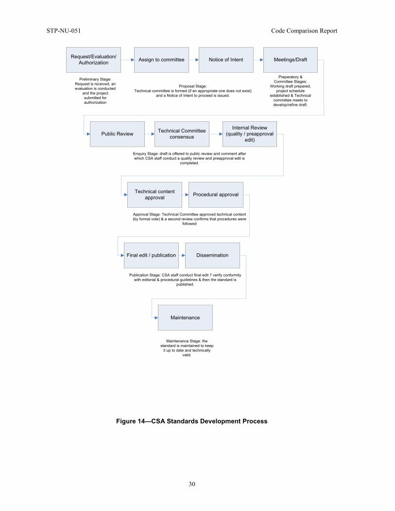
STP-NU-051 Code Comparison Report
30
Request/Evaluation/Authorization Assign to committee Notice of Intent Meetings/Draft
Public Review Technical Committee consensus
Internal Review(quality / preapproval
edit)
Technical content approval Procedural approval
Final edit / publication Dissemination
Maintenance
Preliminary Stage:Request is received, an evaluation is conducted
and the project submitted for authorization
Proposal Stage:Technical committee is formed (if an appropriate one does not exist)
and a Notice of Intent to proceed is issued.
Preparatory & Committee Stages:
Working draft prepared, project schedule
established & Technical committee meets to develop/refine draft.
Enquiry Stage: draft is offered to public review and comment after which CSA staff conduct a quality review and preapproval edit is
completed.
Approval Stage: Technical Committee approved technical content (by formal vote) & a second review confirms that procedures were
followed
Publication Stage: CSA staff conduct final edit 7 verify conformity with editorial & procedural guidelines & then the standard is
published.
Maintenance Stage: the standard is maintained to keep
it up to date and technically valid.
Figure 14—CSA Standards Development Process
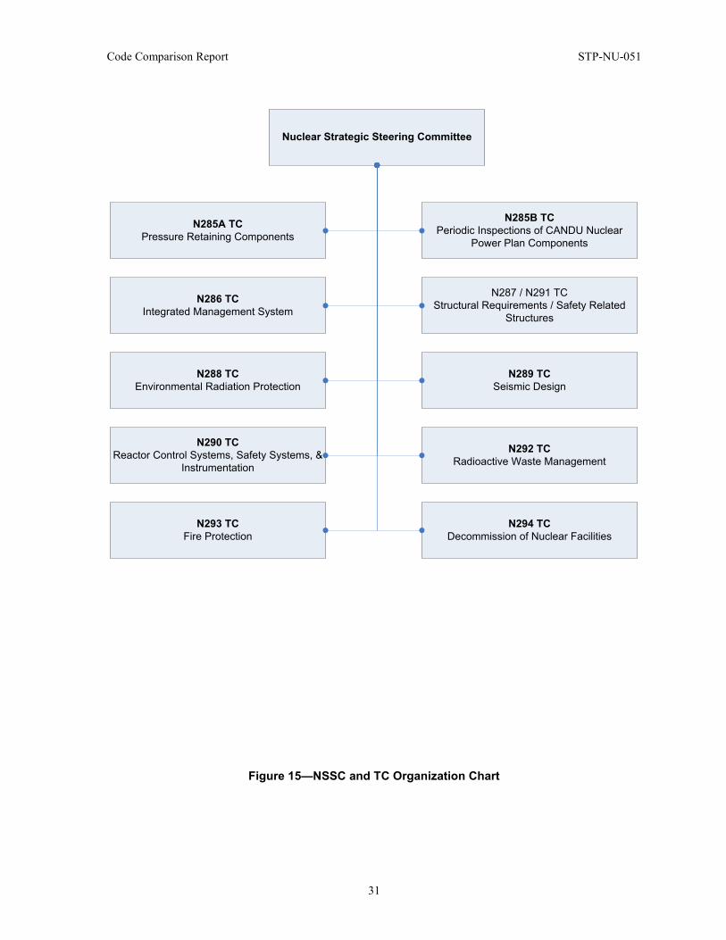
Code Comparison Report STP-NU-051
31
Nuclear Strategic Steering Committee
N285A TCPressure Retaining Components
N286 TCIntegrated Management System
N288 TCEnvironmental Radiation Protection
N290 TCReactor Control Systems, Safety Systems, &
Instrumentation
N293 TCFire Protection
N285B TCPeriodic Inspections of CANDU Nuclear
Power Plan Components
N287 / N291 TCStructural Requirements / Safety Related
Structures
N289 TCSeismic Design
N292 TCRadioactive Waste Management
N294 TCDecommission of Nuclear Facilities
Figure 15—NSSC and TC Organization Chart
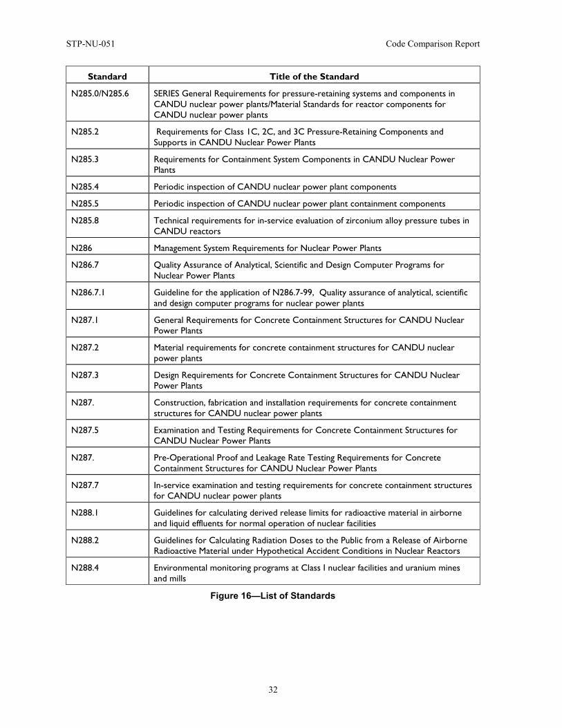
STP-NU-051 Code Comparison Report
32
Standard Title of the Standard
N285.0/N285.6 SERIES General Requirements for pressure-retaining systems and components in CANDU nuclear power plants/Material Standards for reactor components for CANDU nuclear power plants
N285.2 Requirements for Class 1C, 2C, and 3C Pressure-Retaining Components and Supports in CANDU Nuclear Power Plants
N285.3 Requirements for Containment System Components in CANDU Nuclear Power Plants
N285.4 Periodic inspection of CANDU nuclear power plant components
N285.5 Periodic inspection of CANDU nuclear power plant containment components
N285.8 Technical requirements for in-service evaluation of zirconium alloy pressure tubes in CANDU reactors
N286 Management System Requirements for Nuclear Power Plants
N286.7 Quality Assurance of Analytical, Scientific and Design Computer Programs for Nuclear Power Plants
N286.7.1 Guideline for the application of N286.7-99, Quality assurance of analytical, scientific and design computer programs for nuclear power plants
N287.1 General Requirements for Concrete Containment Structures for CANDU Nuclear Power Plants
N287.2 Material requirements for concrete containment structures for CANDU nuclear power plants
N287.3 Design Requirements for Concrete Containment Structures for CANDU Nuclear Power Plants
N287. Construction, fabrication and installation requirements for concrete containment structures for CANDU nuclear power plants
N287.5 Examination and Testing Requirements for Concrete Containment Structures for CANDU Nuclear Power Plants
N287. Pre-Operational Proof and Leakage Rate Testing Requirements for Concrete Containment Structures for CANDU Nuclear Power Plants
N287.7 In-service examination and testing requirements for concrete containment structures for CANDU nuclear power plants
N288.1 Guidelines for calculating derived release limits for radioactive material in airborne and liquid effluents for normal operation of nuclear facilities
N288.2 Guidelines for Calculating Radiation Doses to the Public from a Release of Airborne Radioactive Material under Hypothetical Accident Conditions in Nuclear Reactors
N288.4 Environmental monitoring programs at Class I nuclear facilities and uranium mines and mills
Figure 16—List of Standards
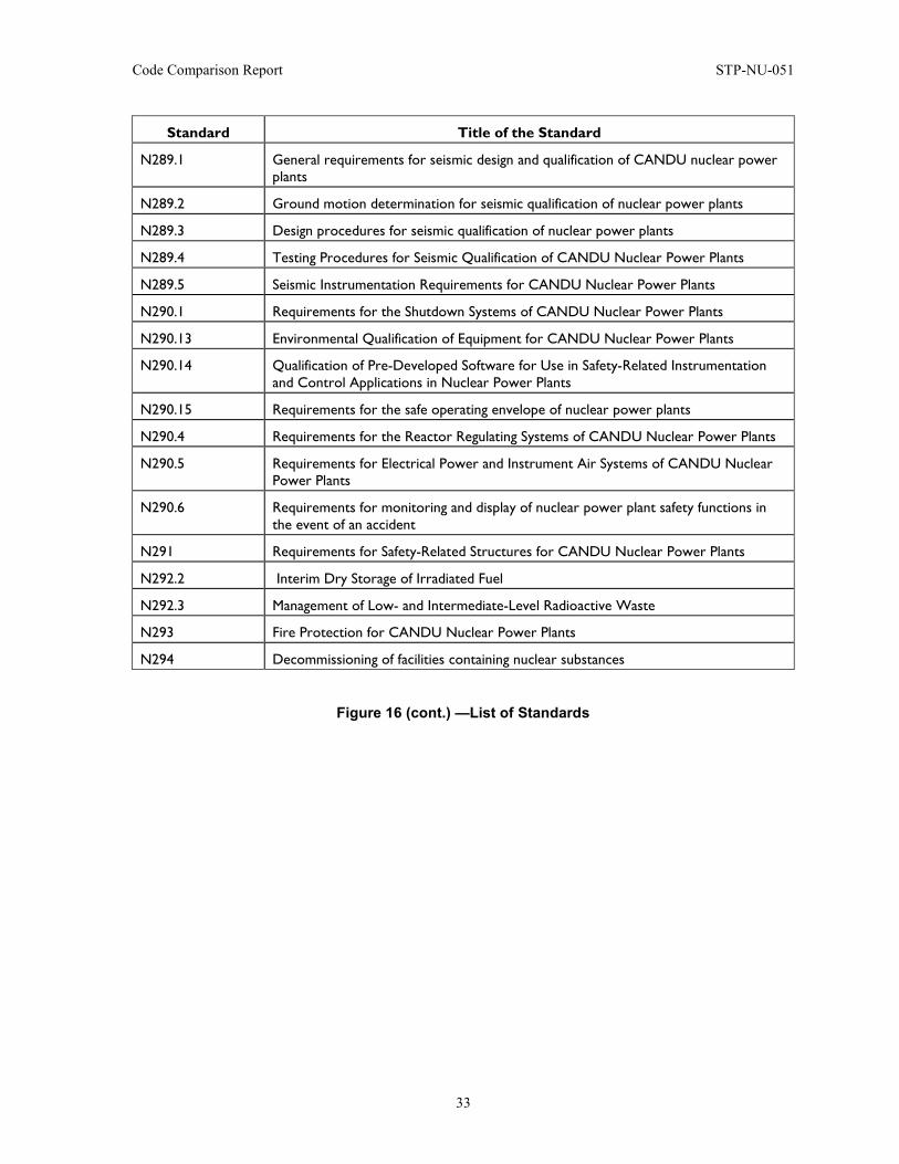
Code Comparison Report STP-NU-051
33
Standard Title of the Standard
N289.1 General requirements for seismic design and qualification of CANDU nuclear power plants
N289.2 Ground motion determination for seismic qualification of nuclear power plants
N289.3 Design procedures for seismic qualification of nuclear power plants
N289.4 Testing Procedures for Seismic Qualification of CANDU Nuclear Power Plants
N289.5 Seismic Instrumentation Requirements for CANDU Nuclear Power Plants
N290.1 Requirements for the Shutdown Systems of CANDU Nuclear Power Plants
N290.13 Environmental Qualification of Equipment for CANDU Nuclear Power Plants
N290.14 Qualification of Pre-Developed Software for Use in Safety-Related Instrumentation and Control Applications in Nuclear Power Plants
N290.15 Requirements for the safe operating envelope of nuclear power plants
N290.4 Requirements for the Reactor Regulating Systems of CANDU Nuclear Power Plants
N290.5 Requirements for Electrical Power and Instrument Air Systems of CANDU Nuclear Power Plants
N290.6 Requirements for monitoring and display of nuclear power plant safety functions in the event of an accident
N291 Requirements for Safety-Related Structures for CANDU Nuclear Power Plants
N292.2 Interim Dry Storage of Irradiated Fuel
N292.3 Management of Low- and Intermediate-Level Radioactive Waste
N293 Fire Protection for CANDU Nuclear Power Plants
N294 Decommissioning of facilities containing nuclear substances
Figure 16 (cont.) —List of Standards
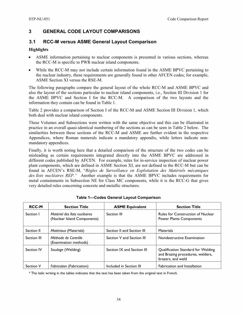
STP-NU-051 Code Comparison Report
34
3 GENERAL CODE LAYOUT COMPARISONS
3.1 RCC-M versus ASME General Layout Comparison Highlights
• ASME information pertaining to nuclear components is presented in various sections, whereas the RCC-M is specific to PWR nuclear island components.
• While the RCC-M may not include certain information found in the ASME BPVC pertaining to the nuclear industry, these requirements are generally found in other AFCEN codes; for example, ASME Section XI versus the RSE-M.
The following paragraphs compare the general layout of the whole RCC-M and ASME BPVC and also the layout of the sections particular to nuclear island components, i.e., Section III Division 1 for the ASME BPVC and Section I for the RCC-M. A comparison of the two layouts and the information they contain can be found in Table 1.
Table 2 provides a comparison of Section I of the RCC-M and ASME Section III Division 1, which both deal with nuclear island components.
These Volumes and Subsections were written with the same objective and this can be illustrated in practice in an overall quasi-identical numbering of the sections as can be seen in Table 2 below. The similarities between these sections of the RCC-M and ASME are further evident in the respective Appendices, where Roman numerals indicate a mandatory appendix, while letters indicate non-mandatory appendices.
Finally, it is worth noting here that a detailed comparison of the structure of the two codes can be misleading as certain requirements integrated directly into the ASME BPVC are addressed in different codes published by AFCEN. For example, rules for in-service inspection of nuclear power plant components, which are defined in ASME Section XI, are not defined in the RCC-M but can be found in AFCEN’s RSE-M, “Règles de Surveillance en Exploitation des Matériels mécaniques des îlots nucléaires REP.” Another example is that the ASME BPVC includes requirements for metal containments in Subsection NE for Class MC components, while it is the RCC-G that gives very detailed rules concerning concrete and metallic structures.
Table 1—Codes General Layout Comparison
RCC-M Section Title ASME Equivalent Section Title
Section I Matériel des îlots nucléaires (Nuclear Island Components)
Section III Rules for Construction of Nuclear Power Plants Components
Section II Matériaux (Materials) Section II and Section III Materials
Section III Méthode de Contrôle (Examination methods)
Section V and Section III Nondestructive Examination
Section IV Soudage (Welding) Section IX and Section III Qualification Standard for Welding and Brazing procedures, welders, brazers, and weld
Section V Fabrication (Fabrication) Included in Section III Fabrication and Installation
* The italic writing in the tables indicates that the text has been taken from the original text in French.
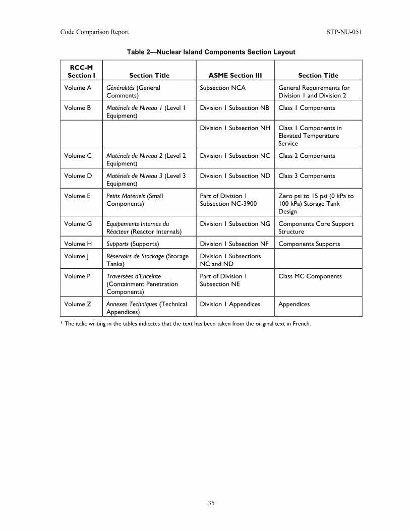
Code Comparison Report STP-NU-051
35
Table 2—Nuclear Island Components Section Layout
RCC-M Section I Section Title ASME Section III Section Title
Volume A Généralités (General Comments)
Subsection NCA General Requirements for Division 1 and Division 2
Volume B Matériels de Niveau 1 (Level 1 Equipment)
Division 1 Subsection NB Class 1 Components
Division 1 Subsection NH Class 1 Components in Elevated Temperature Service
Volume C Matériels de Niveau 2 (Level 2 Equipment)
Division 1 Subsection NC Class 2 Components
Volume D Matériels de Niveau 3 (Level 3 Equipment)
Division 1 Subsection ND Class 3 Components
Volume E Petits Matériels (Small Components)
Part of Division 1 Subsection NC-3900
Zero psi to 15 psi (0 kPa to 100 kPa) Storage Tank Design
Volume G Equipements Internes du Réacteur (Reactor Internals)
Division 1 Subsection NG Components Core Support Structure
Volume H Supports (Supports) Division 1 Subsection NF Components Supports
Volume J Réservoirs de Stockage (Storage Tanks)
Division 1 Subsections NC and ND
Volume P Traversées d’Enceinte (Containment Penetration Components)
Part of Division 1 Subsection NE
Class MC Components
Volume Z Annexes Techniques (Technical Appendices)
Division 1 Appendices Appendices
* The italic writing in the tables indicates that the text has been taken from the original text in French.
STP-NU-051 Code Comparison Report
36
3.2 JSME versus ASME General Layout Comparison Highlights
• ASME Section III information is divided among three JSME Codes.
• ASME BPVC Section III is organized per component class; JSME is organized per component type.
Among the JSME nuclear codes listed in Figure 8, the following three codes are the subject of comparison of Class 1 component rules.
• JSME S-NC1-2008: Rules on Design and Construction for NPPs, Div. 1 LWRs,
• JSME S-NB1-2007: Rules on Welding for NPPs
• JSME S-NJ1-2008: Rules on Materials for Nuclear Facilities.
The first one (NC-1, Design Code) covers the general aspects for the design and construction of nuclear components that include material, design, fabrication, examination, testing and overpressure protection. In this sense, this code is the primary subject of the comparison. The latter two codes give specific requirements on welding and materials, respectively. These two codes are also included in the comparison because some requirements given in ASME Section III Subsection NB are specified in these JSME Codes. For example, some welding-related requirements given in the Article NB-4000 are provided in the Welding Code (S-NB-1) of JSME. Table 3 provides the contents of JSME Design Code.
Observing Table 3, first it is noted that the JSME Sections are structured in a component-oriented manner, while the ASME Sections III Subsections are laid out in a component class-oriented manner (NB for Class 1, NC for class 2 and so on). This comparison of organizational structure of ASME and JSME Codes is schematically illustrated in Figure 17.
Table 4 provides comparison of the structure of Class 1 vessel rules, i.e., Subsection NB of ASME and Subsection PVB of JSME.
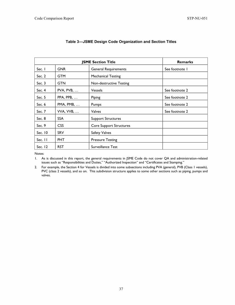
Code Comparison Report STP-NU-051
37
Table 3—JSME Design Code Organization and Section Titles
JSME Section Title Remarks
Sec. 1 GNR General Requirements See footnote 1
Sec. 2 GTM Mechanical Testing
Sec. 3 GTN Non-destructive Testing
Sec. 4 PVA, PVB, … Vessels See footnote 2
Sec. 5 PPA, PPB, … Piping See footnote 2
Sec. 6 PMA, PMB, … Pumps See footnote 2
Sec. 7 VVA, VVB, … Valves See footnote 2
Sec. 8 SSA Support Structures
Sec. 9 CSS Core Support Structures
Sec. 10 SRV Safety Valves
Sec. 11 PHT Pressure Testing
Sec. 12 RST Surveillance Test
Notes: 1. As is discussed in this report, the general requirements in JSME Code do not cover QA and administration-related
issues such as “Responsibilities and Duties,” “Authorized Inspection” and “Certificates and Stamping.” 2. For example, the Section 4 for Vessels is divided into some subsections including PVA (general), PVB (Class 1 vessels),
PVC (class 2 vessels), and so on. This subdivision structure applies to some other sections such as piping, pumps and valves.
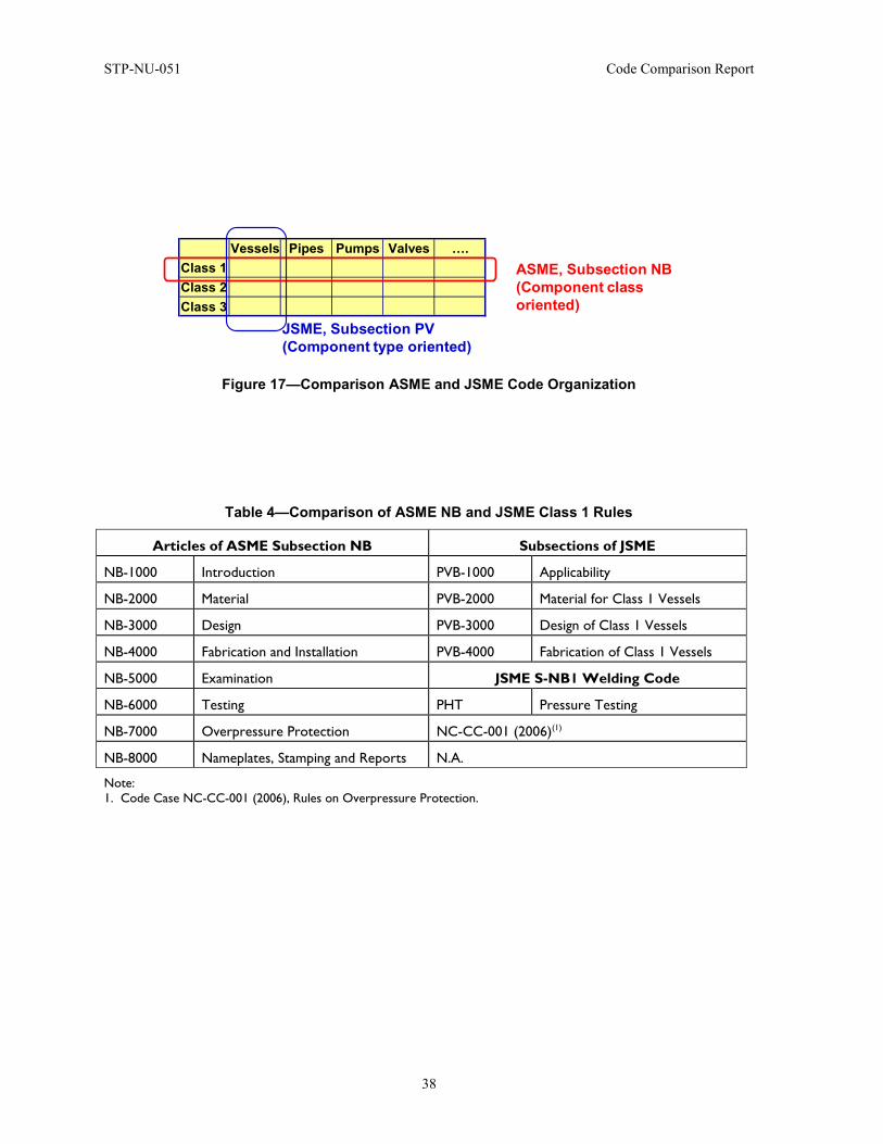
STP-NU-051 Code Comparison Report
38
Figure 17—Comparison ASME and JSME Code Organization
Table 4—Comparison of ASME NB and JSME Class 1 Rules
Articles of ASME Subsection NB Subsections of JSME
NB-1000 Introduction PVB-1000 Applicability
NB-2000 Material PVB-2000 Material for Class 1 Vessels
NB-3000 Design PVB-3000 Design of Class 1 Vessels
NB-4000 Fabrication and Installation PVB-4000 Fabrication of Class 1 Vessels
NB-5000 Examination JSME S-NB1 Welding Code
NB-6000 Testing PHT Pressure Testing
NB-7000 Overpressure Protection NC-CC-001 (2006)(1)
NB-8000 Nameplates, Stamping and Reports N.A.
Note: 1. Code Case NC-CC-001 (2006), Rules on Overpressure Protection.
Vessels Pipes Pumps Valves ….Class 1Class 2Class 3
ASME, Subsection NB(Component class oriented)
JSME, Subsection PV(Component type oriented)
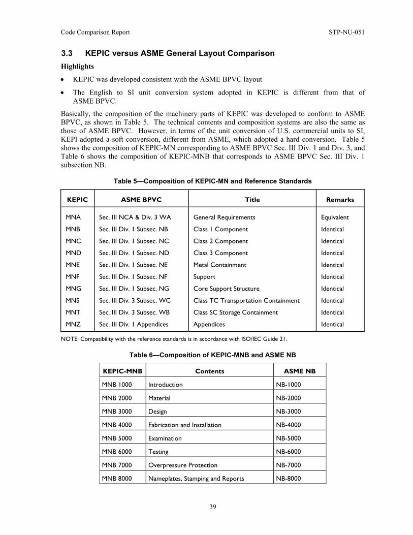
Code Comparison Report STP-NU-051
39
3.3 KEPIC versus ASME General Layout Comparison Highlights
• KEPIC was developed consistent with the ASME BPVC layout
• The English to SI unit conversion system adopted in KEPIC is different from that of ASME BPVC.
Basically, the composition of the machinery parts of KEPIC was developed to conform to ASME BPVC, as shown in Table 5. The technical contents and composition systems are also the same as those of ASME BPVC. However, in terms of the unit conversion of U.S. commercial units to SI, KEPI adopted a soft conversion, different from ASME, which adopted a hard conversion. Table 5 shows the composition of KEPIC-MN corresponding to ASME BPVC Sec. III Div. 1 and Div. 3, and Table 6 shows the composition of KEPIC-MNB that corresponds to ASME BPVC Sec. III Div. 1 subsection NB.
Table 5—Composition of KEPIC-MN and Reference Standards
KEPIC ASME BPVC Title Remarks
MNA
MNB
MNC
MND
MNE
MNF
MNG
MNS
MNT
MNZ
Sec. III NCA & Div. 3 WA
Sec. III Div. 1 Subsec. NB
Sec. III Div. 1 Subsec. NC
Sec. III Div. 1 Subsec. ND
Sec. III Div. 1 Subsec. NE
Sec. III Div. 1 Subsec. NF
Sec. III Div. 1 Subsec. NG
Sec. III Div. 3 Subsec. WC
Sec. III Div. 3 Subsec. WB
Sec. III Div. 1 Appendices
General Requirements
Class 1 Component
Class 2 Component
Class 3 Component
Metal Containment
Support
Core Support Structure
Class TC Transportation Containment
Class SC Storage Containment
Appendices
Equivalent
Identical
Identical
Identical
Identical
Identical
Identical
Identical
Identical
Identical
NOTE: Compatibility with the reference standards is in accordance with ISO/IEC Guide 21.
Table 6—Composition of KEPIC-MNB and ASME NB
KEPIC-MNB Contents ASME NB
MNB 1000 Introduction NB-1000
MNB 2000 Material NB-2000
MNB 3000 Design NB-3000
MNB 4000 Fabrication and Installation NB-4000
MNB 5000 Examination NB-5000
MNB 6000 Testing NB-6000
MNB 7000 Overpressure Protection NB-7000
MNB 8000 Nameplates, Stamping and Reports NB-8000
STP-NU-051 Code Comparison Report
40
3.4 CSA versus ASME General Layout Comparison Highlights
• ASME BPVC is used in various Canadian provinces and N285.0 written to define how ASME BPVC Section III is adopted to fit the Canadian laws.
• N285.0 provides rules for classification of the various components; once classification is done, the relevant ASME BPVC Section III part is used.
The relationship between the ASME Boiler and Pressure Vessel Code and CSA Standards started with non-nuclear areas over 75 years ago. The Canadian Jurisdictions adopted the technical requirements of the ASME Boiler and Pressure Vessel Code as the basis for their acceptance of pressure boundary construction and began participation in their development. This was done mainly through their relationship with the organization known today as the National Board of Boiler and Pressure Vessel Inspectors, of which all Provinces and Territories of Canada participate as members. This not only provided them an entry into the U.S. markets but also mitigated the need to develop a similar document in Canada.
Regulation of safety is a provincial responsibility and each Province has its own laws and processes through which the construction of the pressure boundary is controlled. It was apparent that there was a need to develop interfacing documents that allowed the application of the ASME Boiler and Pressure Vessel Code in the various Provinces and Territories and to provide some consistency in approach throughout Canada. The CSA Standard B51 was the vehicle that was developed to provide this consistency. It defined how the ASME BPVC is adopted in Canada. This approach has proven to be very successful over the years.
With introduction of nuclear power and the development of the CANDU concept as Canada’s contribution to the industry, it became obvious that a document similar to B51 would provide similar benefits. This was particularly true for nuclear power because the CANDU concept introduced materials, components and methods of construction that were not part of the ASME BPVC that was developing. The Section III Code was being written to facilitate the development and use of the U.S. concepts and with the heavy influence of the USA Regulatory Authority, the USNRC, some of the CANDU requirements could not be met at that time. In was in this milieu that the Canadian Standard N285.1 was developed in the mid-1970s. Starting in 1980 a new Standard CSA N285.0 was written and this became the upper tier document in a series of Standards.
N285.0 has evolved over the years but essentially it filled the same purpose as the B51 document; it provided the approach for adopting the ASME BPVC for use in the construction of the CANDU pressure boundary. Besides providing this intermediate document, other members of the Series provided requirements for the use of the materials and components that were unique to the CANDU concept. However, even in these cases, the technical requirements of Section III have been adopted when they are applicable.
N285.0 provides rules for classification of the process and special safety systems and, by default, the classification of the components in those systems or section of systems. Once the classification of a component has been defined, the requirements for the construction of the ASME BPVC can be used to construct the component. Only those items that are unique to the CANDU concept use the other CSA Standards and, even in these cases, they are referenced directly to a section of the Section III Code for technical requirements.
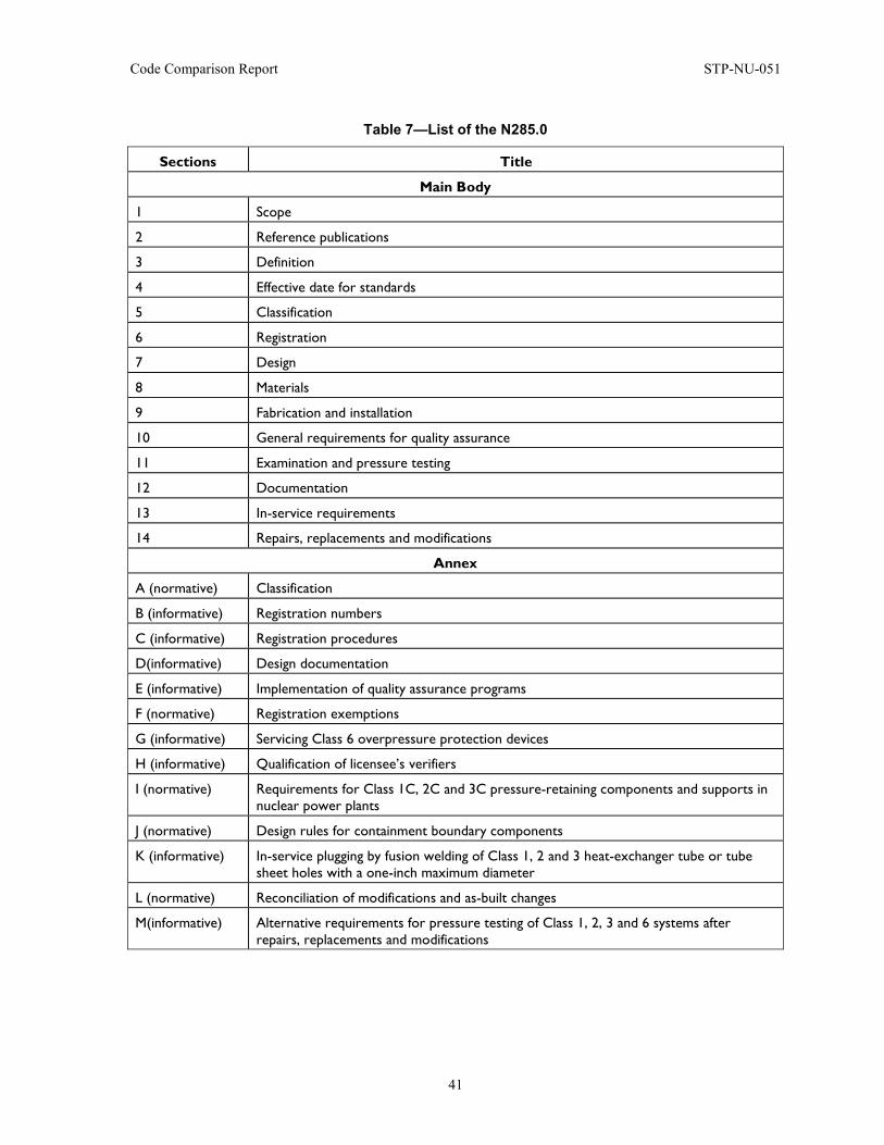
Code Comparison Report STP-NU-051
41
Table 7—List of the N285.0
Sections Title
Main Body
1 Scope
2 Reference publications
3 Definition
4 Effective date for standards
5 Classification
6 Registration
7 Design
8 Materials
9 Fabrication and installation
10 General requirements for quality assurance
11 Examination and pressure testing
12 Documentation
13 In-service requirements
14 Repairs, replacements and modifications
Annex
A (normative) Classification
B (informative) Registration numbers
C (informative) Registration procedures
D(informative) Design documentation
E (informative) Implementation of quality assurance programs
F (normative) Registration exemptions
G (informative) Servicing Class 6 overpressure protection devices
H (informative) Qualification of licensee’s verifiers
I (normative) Requirements for Class 1C, 2C and 3C pressure-retaining components and supports in nuclear power plants
J (normative) Design rules for containment boundary components
K (informative) In-service plugging by fusion welding of Class 1, 2 and 3 heat-exchanger tube or tube sheet holes with a one-inch maximum diameter
L (normative) Reconciliation of modifications and as-built changes
M(informative) Alternative requirements for pressure testing of Class 1, 2, 3 and 6 systems after repairs, replacements and modifications
STP-NU-051 Code Comparison Report
42
4 RCC-M VERSUS ASME BPVC SECTION III COMPARISON
4.1 Abstract The American and French nuclear industries are among the two largest in the world. In these two countries though, the evolution of two different codes has developed, the RCC-M Code in France and the ASME BPVC in the U.S., and although the RCC-M Code has its roots based on Section III of the ASME BPVC, they have diverged over the years. With the globalization of the markets today, the different existing codes can lead to a barrier for manufacturers used to working with one code and then switching to another.
As of today, there exists a set of practical examples as well as various documents that have been drafted to compare the codes, but no report reflecting mutual agreement and effort from French and American parties exists. This part of the report attempts to fill this gap.
The sections compared here are based on Section III from the ASME BPVC versus the RCC-M Code. Starting from a line-by-line comparison of the two codes, each paragraph of the codes was ranked in four categories, varying from “same” to “technically different.” The main body of this section was then built based on the identified main differences from the line-by-line comparison.
The first conclusion is that the two codes are dissimilar in many aspects. However, most differences can be classified in two categories: differences due to technical requirements and differences due to regulatory requirements. A reconciliation of the technical differences is manageable, provided additional work is carried out, while the regulatory differences would require political and regulatory effort.
This part has identified the main differences between the codes, technical and regulatory. For the technical part, this section constitutes a tool for an owner (manufacturer, designer, etc.) wanting to assess the differences between the two codes. It will enable the individual to highlight the areas where in-depth technical knowledge is required to bridge the gap between the codes. Concerning the regulatory requirements, they are dependent on the politics and cultural background of the countries, so would be more resistant to modification.
4.2 Introduction The objective of this section is to summarize the major differences identified in the specific comparison of the two codes, ASME BPVC and RCC-M Code. This specific comparison is presented as an attachment (Appendix 1) of this report. Indications between brackets will be given when a paragraph from this text relates directly to the table in Appendix 1. In the case that certain sections of either of the two codes are not mentioned in this summary, this implies that there are no significant differences between the two codes in this area. While the detailed comparison provided in Appendix 1 may identify some specific differences, these were considered to have no real impact in practice.
For Class 1 vessels, the RCC-M is generally more prescriptive than ASME Section III; ASME has a larger scope than RCC-M while RCC-M focuses specifically on PWR components.
RCC-M and ASME Section III are used with a different QA organization.
Many differences are reported and will lead to non-conformances with existing regulator practices, but many of these differences can be solved by the manufacturer through complementary requirements.
Again, it is necessary to bear in mind that the main idea is to provide a general overview of any significant dissimilarity between the codes and permit an assessment of how these differences might impact various regulatory and licensing requirements.
Code Comparison Report STP-NU-051
43
As a reminder, the two codes that will be compared here are the ASME 2007 Edition and the RCC-M 2007 Edition without any consulting of the additional Addenda published after 2007, generally without appendices or code cases consideration.
The ASME BPVC has today become an international standard to design pressure and mechanical equipment as a whole. On the other hand, the RCC-M has grown to become an internationally recognized code in the nuclear industry, being also used worldwide in countries such as, among others, Korea, China, South Africa and Finland. Nevertheless, when assessing the differences between the RCC-M and ASME BPVC, the original basis for development of these respective codes should be kept in mind.
The ASME BPVC aims at laying down rules for nuclear components as a whole, as its title indicates for multiple types of nuclear power plant designs. On the other hand, the RCC-M Code is focused mainly on the rules for construction of mechanical equipment for PWR reactors. This difference implies having information in the ASME BPVC relating to the nuclear industry scattered in different sections. This last point is particularly important when comparing the codes section to section, as is done in the rest of this Section.
The first subsection compares the NB-1000 preliminary paragraphs from the ASME BPVC to their equivalents from the RCC-M Code. The second subsection addresses the NB-2000 paragraphs about materials and the third one deals with the NB-3000 paragraphs about design. The NB-4000 about fabrication and installation is discussed in the subsection named Fabrication and Welding. Examination from the NB-5000 is dealt with in the subsection with the same name. The NB-6000 paragraphs about testing are partially covered in the subsection named Pressure Tests. NB-7000 about overpressure protection is addressed in the last subsection before a short overview on quality aspects in the codes, and the Conclusion.
4.3 Preliminary Paragraphs and Scope Presentation Highlights
• No stamping and no certificate holder in RCC-M • No boundaries of jurisdiction consideration in RCC-M.
This section aims at describing the differences between the preliminary paragraphs Section III Division 1 NB-1000 of the ASME BPVC and their equivalent in the RCC-M Code.
In the American code, these paragraphs give an introduction to the contents of the Section III Division 1 NB paragraphs and, more importantly, define the scope of the section. Conversely, in the closest section in the RCC-M, which is Section I B-1000, the route taken is different: this paragraph goes over the documents that are required and should be kept at the disposition of the surveillance agents as well as the identification to be used. These differences in the layouts are best summarized in Tables 8 and 9. But beyond these line-by-line comparison discrepancies, more important differences in the two codes should be commented on here.
The rest of this section is organized in three paragraphs. The first provides comments on the differences between the two codes as regards the practices used, such as stamping and certificate holders, as well as the Design Specification. A second part describes deterioration aspects and, finally, a third paragraph deals with the jurisdictional boundary definition and penetration assemblies.
A first comment about the two codes pertains to stamping and certificate holders. In the ASME BPVC, it is specified in Section III Division 1 NB-1110 (a) that the “Subsection NB contains rules for the material, […], stamping, and preparation reports by the Certificate Holder […].” The RCC-M does not have any stamping or certificate holders (Appendix 1 – line NB-1110). This point will be developed more in detail in the paragraph about overview of quality aspects. Moreover, the term
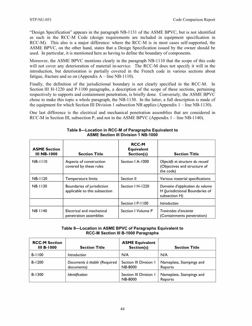
STP-NU-051 Code Comparison Report
44
“Design Specification” appears in the paragraph NB-1131 of the ASME BPVC, but is not identified as such in the RCC-M Code (design requirements are included in equipment specification in RCC-M). This also is a major difference: where the RCC-M is in most cases self-supported, the ASME BPVC, on the other hand, states that a Design Specification issued by the owner should be used. In particular, it is mentioned here as having to define the boundary of components.
Moreover, the ASME BPVC mentions clearly in the paragraph NB-1110 that the scope of this code will not cover any deterioration of material in-service. The RCC-M does not specify it will in the introduction, but deterioration is partially covered in the French code in various sections about fatigue, fracture and so on (Appendix A – line NB-1110).
Finally, the definition of the jurisdictional boundary is not clearly specified in the RCC-M. In Section III H-1220 and P-1100 paragraphs, a description of the scope of these sections, pertaining respectively to supports and containment penetration, is briefly done. Conversely, the ASME BPVC chose to make this topic a whole paragraph, the NB-1130. In the latter, a full description is made of the equipment for which Section III Division 1 subsection NB applies (Appendix 1 – line NB-1130).
One last difference is the electrical and mechanical penetration assemblies that are considered in RCC-M in Section III, subsection P, and not in the ASME BPVC (Appendix 1 – line NB-1140).
Table 8—Location in RCC-M of Paragraphs Equivalent to ASME Section III Division 1 NB-1000
ASME Section III NB-1000 Section Title
RCC-M Equivalent Section(s) Section Title
NB-1110 Aspects of construction covered by these rules
Section I A-1000 Objectifs et structure du recueil (Objectives and structure of the code)
NB-1120 Temperature limits Section II Various material specifications
NB 1130 Boundaries of jurisdiction applicable to this subsection
Section I H-1220 Domaine d’application du volume H (Jurisdictional Boundaries of subsection H)
Section I P-1100 Introduction
NB 1140 Electrical and mechanical penetration assemblies
Section I Volume P Traversées d’enceinte (Containments penetration)
Table 9—Location in ASME BPVC of Paragraphs Equivalent to RCC-M Section III B-1000 Paragraphs
RCC-M Section III B-1000 Section Title
ASME Equivalent Section(s) Section Title
B-1100 Introduction N/A N/A
B-1200 Documents à établir (Required documents)
Section III Division 1 NB-8000
Nameplate, Stampings and Reports
B-1300 Identification Section III Division 1 NB-8000
Nameplate, Stampings and Reports
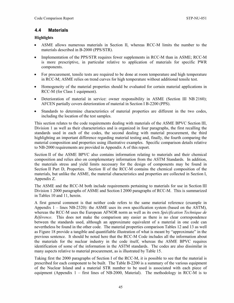
Code Comparison Report STP-NU-051
45
4.4 Materials Highlights
• ASME allows numerous materials in Section II, whereas RCC-M limits the number to the materials described in B-2000 (PPS/STR).
• Implementation of the PPS/STR requires fewer supplements in RCC-M than in ASME; RCC-M is more prescriptive, in particular relative to application of materials for specific PWR components.
• For procurement, tensile tests are required to be done at room temperature and high temperature in RCC-M; ASME relies on trend curves for high temperature without additional tensile test.
• Homogeneity of the material properties should be evaluated for certain material applications in RCC-M (for Class 1 equipment).
• Deterioration of material in service: owner responsibility in ASME (Section III NB 2160); AFCEN partially covers deterioration of material in Section I B-2200 (PPS).
• Standards to determine characteristics of material properties are different in the two codes, including the location of the test samples.
This section relates to the code requirements dealing with materials of the ASME BPVC Section III, Division 1 as well as their characteristics and is organized in four paragraphs, the first recalling the standards used in each of the codes, the second dealing with material procurement, the third highlighting an important difference regarding material testing and, finally, the fourth comparing the material composition and properties using illustrative examples. Specific comparison details relative to NB-2000 requirements are provided in Appendix A of this report.
Section II of the ASME BPVC also contains information relating to materials and their chemical composition and relies also on complementary information from the ASTM Standards. In addition, the materials stress and yield limits necessary for the design of components may be found in Section II Part D, Properties. Section II of the RCC-M contains the chemical composition of the materials, but unlike the ASME, the material characteristics and properties are collected in Section I, Appendix Z.
The ASME and the RCC-M both include requirements pertaining to materials for use in Section III Division 1 2000 paragraphs of ASME and Section I 2000 paragraphs of RCC-M. This is summarized in Tables 10 and 11, herein.
A first general comment is that neither code refers to the same material reference (example in Appendix 1 – lines NB-2320): the ASME uses its own specification system (based on the ASTM), whereas the RCC-M uses the European AFNOR norm as well as its own Spécification Technique de Référence. This does not make the comparison any easier as there is no clear correspondence between the standards used, although an approximate equivalent of a material in one code can nevertheless be found in the other code. The material properties comparison Tables 12 and 13 as well as Figure 18 provide a tangible and quantifiable illustration of what is meant by “approximate” in the previous sentence. It should be noted here that the RCC-M Code includes all the information about the materials for the nuclear industry in the code itself, whereas the ASME BPVC requires identification of some of the information in the ASTM standards. The codes are also dissimilar in many aspects relative to material procurement, as is illustrated by Table 15.
Taking first the 2000 paragraphs of Section I of the RCC-M, it is possible to see that the material is prescribed for each component to be built. The Table B-2200 is a summary of the various equipment of the Nuclear Island and a material STR number to be used is associated with each piece of equipment (Appendix 1 – first lines of NB-2000, Material). The methodology in RCC-M is to
STP-NU-051 Code Comparison Report
46
impose a material (or to select one from a list of materials) according to the level and nature of the product or part. For example, the aforementioned Table B-2200 imposes PPS (STR) M2115 for the material of tube plate of steam generators, to which the ASME BPVC Section II equivalent would be the SA-508/SA-508 M. Note that, in addition, the PPS (STR) in Section II of RCC-M also defines associated tests and NDE, which are not required as mandatory for SA-508/SA-508 M. The scope of RCC-M is therefore not identical to that of ASME Section II for material specification: the ASME BPVC gives a selection of different alternatives, with one to be retained in the purchase order with associated procurement specification.
On the other hand, looking at Section III Division 1 of the ASME and the 2000 paragraphs, these include general requirements on the materials that should be used for each component. An example of such a paragraph is Section III Division 1, Section NB-2120 relating to pressure-retaining material. The paragraph gives general requirements but leaves freedom to the designer to select the material. The idea in ASME Section III is that the owner has not to completely define and choose the material in the design specification. Nevertheless, the design report issued by the designer and certified by a Registered Professional Engineer (RPE) must allow the N-certificate holder to issue the material specification that will be used, within adequately defined conditions, by the material manufacturer. Only with this process, optional parts of ASME Section III like Appendix W, which is never called in the body of the Section III, can become mandatory. This should, in this case, be specified by the owner or the designer. Each actor in the decision process has a responsibility that will, in the end, guarantee a material selection equivalent to the RCC-M (such as the M2115 versus SA-508/SA-508 M mentioned above).
To end this discussion, it should be highlighted that if materials are selected from Section II of the ASME BPVC, used along with Appendix II only, and that in addition the selection is done by a designer without an RPE and/or by a material producer without any quality management certification, it is impossible to guarantee a final material equivalent to the RCC-M one.
Another discrepancy lies in the material testing and more specifically the tensile tests (Appendix 1 – line NB-2340). Considering two materials of very similar chemical composition, the SA-508 Grade 3 in the ASME and the 16MND5 in the RCC-M, which can respectively be found in Section II SA-508/SA-508M and in Section II Section M2111, it can be seen that:
• In Part 6.0 of the section of the ASME mentioned above, there is no need for a high-temperature tensile test and only a room temperature one.
• In the section of the RCC-M specified above, it is mentioned clearly in part 4.3 a requirement for “tension testing at room temperature and at high temperature.”
Similar requirements can be found in different parts of the two codes when assessing the mechanical requirements for other materials. Among other parts of the RCC-M, a high-temperature tensile test is also required for filler material acceptance (Section IV, Section S-2536).
The discussion from the previous paragraph about material procurement explains this difference. These tests are justified in RCC-M to ascertain the characteristics at ambient temperature of the material ordered and/or supplied. ASME, on the other hand, considers that the attentive survey of the Third Party will ascertain that the required characteristics, ordered with the appropriate documentation (see previous paragraph) and with the adequate testing requirements, meet the actual characteristics of the material supplied. The absence of a Third Party in the RCC-M Code is compensated by a series of additional tests.
Moreover, the ASME BPVC relies on other design factors to account for uncertainties in the material properties given in Section II. As an example, looking at Figure 19 and at the ultimate strength of the SA-336 Cl F316LN and of the Z2CND18-12, it can be seen that the allowable of the former is much lower than that of the latter.
Code Comparison Report STP-NU-051
47
A last set of differences to mention in this subsection is the tests to be performed: RCC-M uses Charpy V-notch test, drop weight test, or calculates RTNDT with ISO standard as a basis, whereas ASME uses U.S. standards, as mentioned in the paragraph NB-2300 of the ASME BPVC (Appendix 1 – line NB-2320). The discrepancies in the values used can be seen in Table 14. The same comments could be made for examination and repair (NB-2500) and material organization quality system programs (NB-2600).
Concerning the material composition and using as an example the SA-508 Grade 3 in the ASME and the 16MND5 in the RCC-M, which can respectively be found in Section II SA-508/SA-508M and in Section II Section M-2111, it can be seen that the prescriptions in chemical compositions are different as regards the contents, as can be seen in Table 12. For example, cobalt content is 0.03% in M-2111 in RCC-M and not mentioned in SA-508. When working with the ASME BPVC, the designer may recall and/or impose these limits in the technical specifications based on the experience gathered through the years. In practice, two materials produced as per ASME requirements and RCC-M requirements will potentially have differences in their chemical composition, but it is of the responsibility of the owner or designer to add extra requirements that ensure adequate quality.
For example, designer will have to address:
• The need to minimize intergranular attack in austenitic stainless steels as in Section I B-2300 of RCC-M
• The need of material cleanliness for long-term service as in B-3176 of RCC-M
• Lamellar tearing as in B-3177 of RCC-M.
Multiple other differences could be found concerning the material composition and selection, but this discussion will be ended here. See Appendix 1 for other differences. All the examples given above lead indeed to one conclusion: the ASME leaves much more responsibility and/or freedom to the owner or designer. It is not self-supporting and relies on additional specifications. The RCC-M gives a very detailed listing of the steps that should be followed and the materials allowed. Finally, regarding the Class 1 material properties, two illustrative examples will be taken with the SA-508 Grade 3 Class 2 in the ASME and the 16MND5 (M2111) in the RCC-M, already selected above, and the SA-336 Cl F316LN and Z2CND18-12 (M3301, diameter bigger than 150 mm). As can be seen in Figures 19 and 20, the compared properties as regards design stress, yield strength and ultimate strength are very similar. As mentioned above, the ultimate strength allowable is sometimes lower for the materials in the ASME to compensate for the fact of not carrying out tensile tests at high temperatures. The comparison between the 16MND5 and the SA-508 Grade 3 Class 2 is more extensive and can be seen in Tables 12 to 14.
An additional requirement found in the RCC-M regarding the properties is the assessment of the latter within the material. Concerning main components (M140) and new material qualification, in RCC-M Section M-143.6, it is stated that when qualifying a component or part, the fabricator should assess the homogeneity of the material (Appendix 1 – lines NB-2221 and NB-2223). No such requirement can be found in the ASME. A dedicated requirement for main parts is the technical qualification M 140 for forged parts and M160 for main castings. This is explained in the section on Fabrication – Welding.
To conclude, the main differences for this section are first, the responsibility that the ASME leaves to the ordering chain (owner, designer, Third Party, and/or supplier), whereas the RCC-M will typically be more prescriptive.
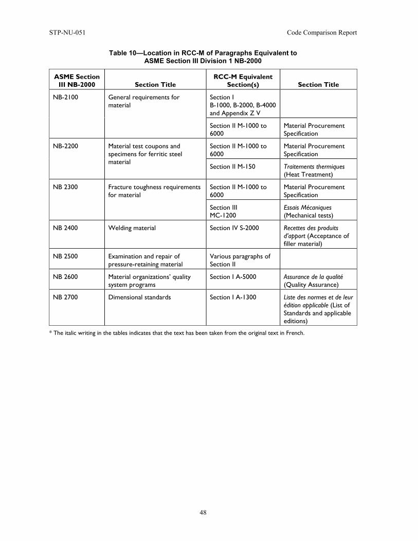
STP-NU-051 Code Comparison Report
48
Table 10—Location in RCC-M of Paragraphs Equivalent to ASME Section III Division 1 NB-2000
ASME Section III NB-2000 Section Title
RCC-M Equivalent Section(s) Section Title
NB-2100 General requirements for material
Section I B-1000, B-2000, B-4000 and Appendix Z V
Section II M-1000 to 6000
Material Procurement Specification
NB-2200 Material test coupons and specimens for ferritic steel material
Section II M-1000 to 6000
Material Procurement Specification
Section II M-150 Traitements thermiques (Heat Treatment)
NB 2300 Fracture toughness requirements for material
Section II M-1000 to 6000
Material Procurement Specification
Section III MC-1200
Essais Mécaniques (Mechanical tests)
NB 2400 Welding material Section IV S-2000 Recettes des produits d’apport (Acceptance of filler material)
NB 2500 Examination and repair of pressure-retaining material
Various paragraphs of Section II
NB 2600 Material organizations’ quality system programs
Section I A-5000 Assurance de la qualité (Quality Assurance)
NB 2700 Dimensional standards Section I A-1300 Liste des normes et de leur édition applicable (List of Standards and applicable editions)
* The italic writing in the tables indicates that the text has been taken from the original text in French.
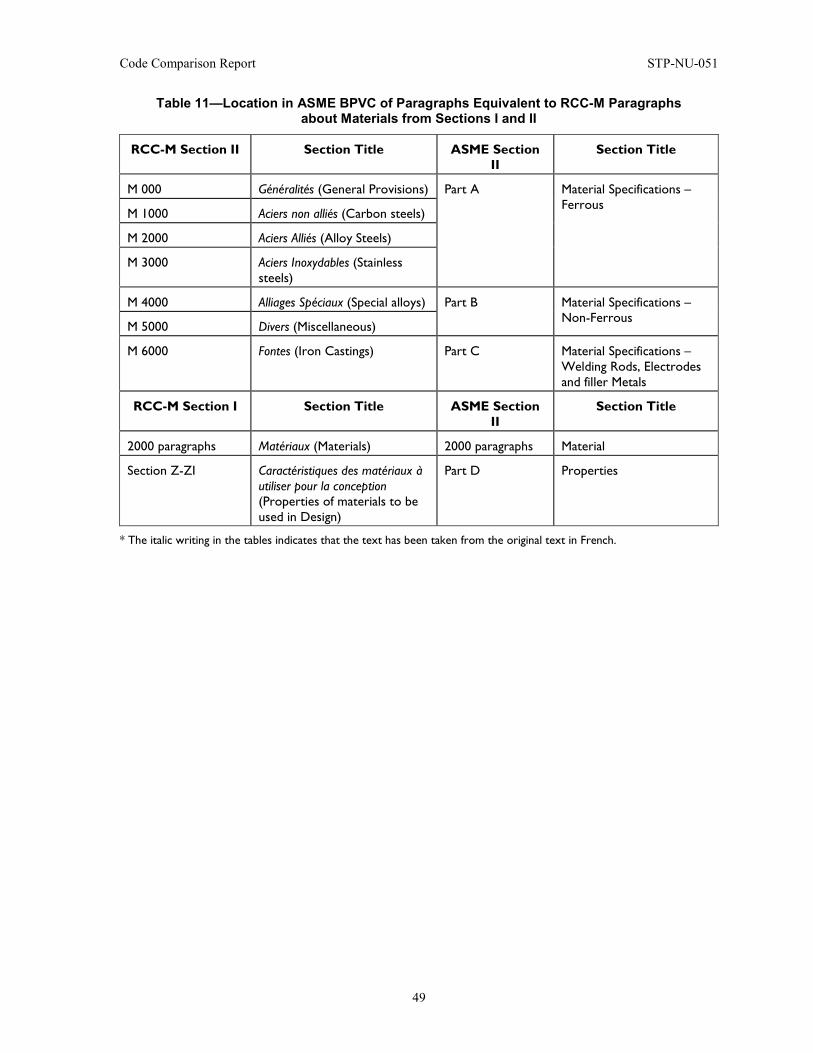
Code Comparison Report STP-NU-051
49
Table 11—Location in ASME BPVC of Paragraphs Equivalent to RCC-M Paragraphs about Materials from Sections I and II
RCC-M Section II Section Title ASME Section II
Section Title
M 000 Généralités (General Provisions) Part A Material Specifications – Ferrous
M 1000 Aciers non alliés (Carbon steels)
M 2000 Aciers Alliés (Alloy Steels)
M 3000 Aciers Inoxydables (Stainless steels)
M 4000 Alliages Spéciaux (Special alloys) Part B Material Specifications – Non-Ferrous
M 5000 Divers (Miscellaneous)
M 6000 Fontes (Iron Castings) Part C Material Specifications – Welding Rods, Electrodes and filler Metals
RCC-M Section I Section Title ASME Section II
Section Title
2000 paragraphs Matériaux (Materials) 2000 paragraphs Material
Section Z-ZI Caractéristiques des matériaux à utiliser pour la conception (Properties of materials to be used in Design)
Part D Properties
* The italic writing in the tables indicates that the text has been taken from the original text in French.
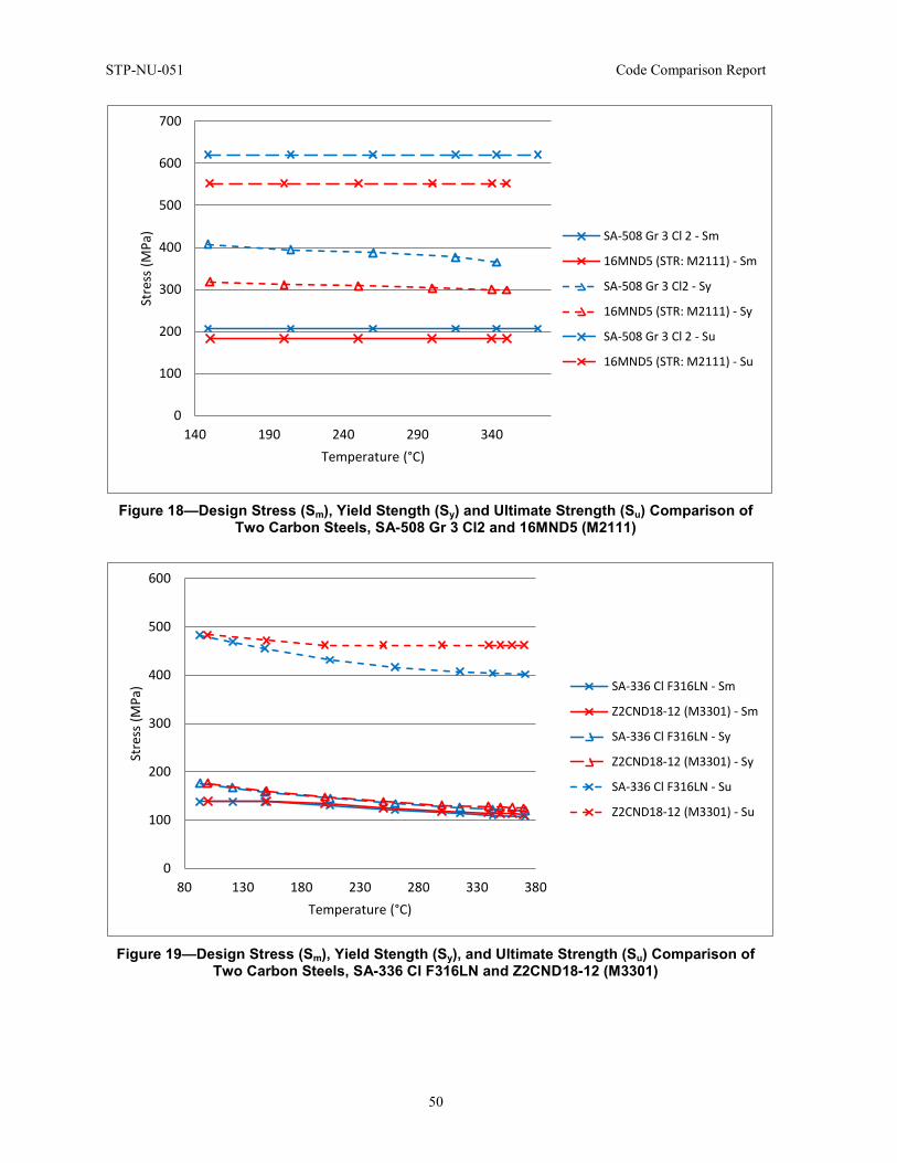
STP-NU-051 Code Comparison Report
50
Figure 18—Design Stress (Sm), Yield Stength (Sy) and Ultimate Strength (Su) Comparison of
Two Carbon Steels, SA-508 Gr 3 Cl2 and 16MND5 (M2111)
Figure 19—Design Stress (Sm), Yield Stength (Sy), and Ultimate Strength (Su) Comparison of
Two Carbon Steels, SA-336 Cl F316LN and Z2CND18-12 (M3301)
0
100
200
300
400
500
600
700
140 190 240 290 340
Stre
ss (M
Pa)
Temperature (°C)
SA-508 Gr 3 Cl 2 - Sm
16MND5 (STR: M2111) - Sm
SA-508 Gr 3 Cl2 - Sy
16MND5 (STR: M2111) - Sy
SA-508 Gr 3 Cl 2 - Su
16MND5 (STR: M2111) - Su
0
100
200
300
400
500
600
80 130 180 230 280 330 380
Stre
ss (M
Pa)
Temperature (°C)
SA-336 Cl F316LN - Sm
Z2CND18-12 (M3301) - Sm
SA-336 Cl F316LN - Sy
Z2CND18-12 (M3301) - Sy
SA-336 Cl F316LN - Su
Z2CND18-12 (M3301) - Su
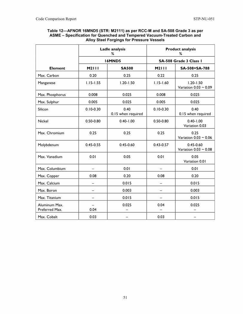
Code Comparison Report STP-NU-051
51
Table 12—AFNOR 16MND5 (STR: M2111) as per RCC-M and SA-508 Grade 3 as per ASME – Specification for Quenched and Tempered Vacuum-Treated Carbon and
Alloy Steel Forgings for Pressure Vessels
Element
Ladle analysis %
Product analysis %
16MND5 SA-508 Grade 3 Class 1
M2111 SA508 M2111 SA-508+SA-788
Max. Carbon 0.20 0.25 0.22 0.25
Manganese 1.15-1.55 1.20-1.50 1.15-1.60 1.20-1.50 Variation 0.03 ~ 0.09
Max. Phosphorus 0.008 0.025 0.008 0.025
Max. Sulphur 0.005 0.025 0.005 0.025
Silicon 0.10-0.30 0.40 0.15 when required
0.10-0.30 0.40 0.15 when required
Nickel 0.50-0.80 0.40-1.00 0.50-0.80 0.40-1.00 Variation 0.03
Max. Chromium 0.25 0.25 0.25 0.25 Variation 0.03 ~ 0.06
Molybdenum 0.45-0.55 0.45-0.60 0.43-0.57 0.45-0.60 Variation 0.03 ~ 0.08
Max. Vanadium 0.01 0.05 0.01 0.05 Variation 0.01
Max. Columbium – 0.01 – 0.01
Max. Copper 0.08 0.20 0.08 0.20
Max. Calcium – 0.015 – 0.015
Max. Boron – 0.003 – 0.003
Max. Titanium – 0.015 – 0.015
Aluminum Max. Preferred Max.
– 0.04
0.025 –
0.04 –
0.025 –
Max. Cobalt 0.03 – 0.03 –
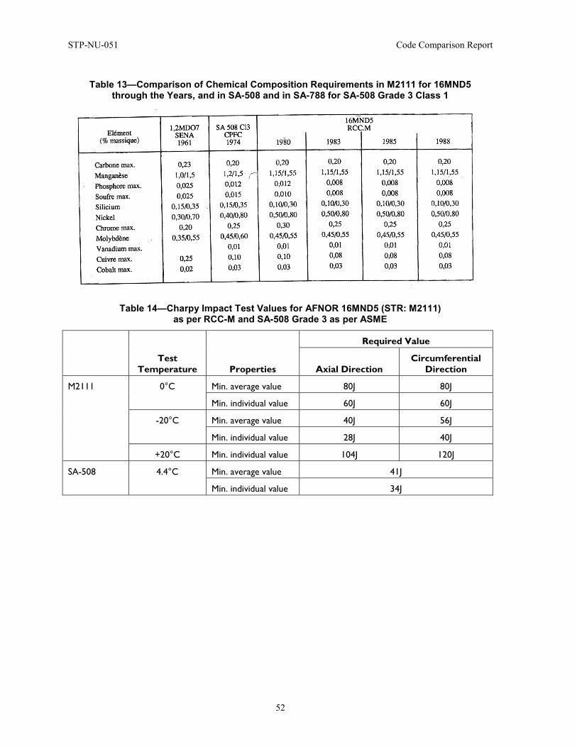
STP-NU-051 Code Comparison Report
52
Table 13—Comparison of Chemical Composition Requirements in M2111 for 16MND5 through the Years, and in SA-508 and in SA-788 for SA-508 Grade 3 Class 1
Table 14—Charpy Impact Test Values for AFNOR 16MND5 (STR: M2111) as per RCC-M and SA-508 Grade 3 as per ASME
Test
Temperature Properties
Required Value
Axial Direction Circumferential
Direction
M2111 0°C Min. average value 80J 80J
Min. individual value 60J 60J
-20°C Min. average value 40J 56J
Min. individual value 28J 40J
+20°C Min. individual value 104J 120J
SA-508 4.4°C Min. average value 41J
Min. individual value 34J
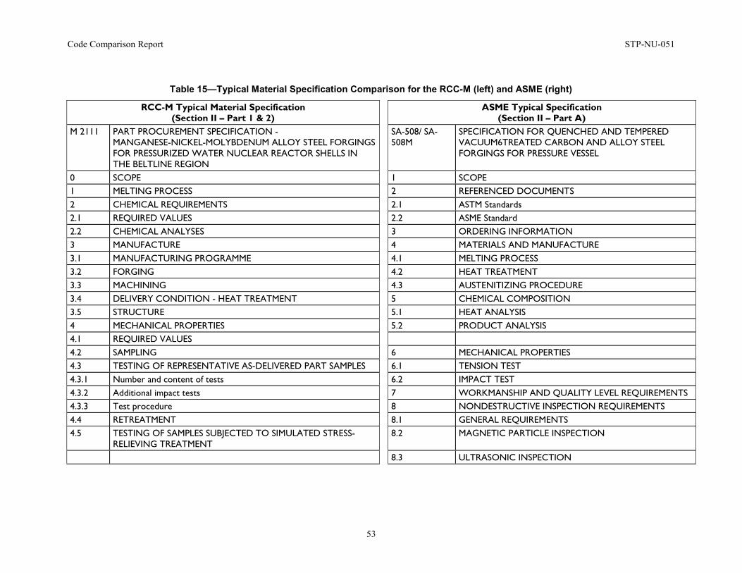
Code Comparison Report STP-NU-051
53
Table 15—Typical Material Specification Comparison for the RCC-M (left) and ASME (right)
RCC-M Typical Material Specification (Section II – Part 1 & 2)
ASME Typical Specification (Section II – Part A)
M 2111 PART PROCUREMENT SPECIFICATION - MANGANESE-NICKEL-MOLYBDENUM ALLOY STEEL FORGINGS FOR PRESSURIZED WATER NUCLEAR REACTOR SHELLS IN THE BELTLINE REGION
SA-508/ SA-508M
SPECIFICATION FOR QUENCHED AND TEMPERED VACUUM6TREATED CARBON AND ALLOY STEEL FORGINGS FOR PRESSURE VESSEL
0 SCOPE 1 SCOPE 1 MELTING PROCESS 2 REFERENCED DOCUMENTS 2 CHEMICAL REQUIREMENTS 2.1 ASTM Standards 2.1 REQUIRED VALUES 2.2 ASME Standard 2.2 CHEMICAL ANALYSES 3 ORDERING INFORMATION 3 MANUFACTURE 4 MATERIALS AND MANUFACTURE 3.1 MANUFACTURING PROGRAMME 4.1 MELTING PROCESS 3.2 FORGING 4.2 HEAT TREATMENT 3.3 MACHINING 4.3 AUSTENITIZING PROCEDURE 3.4 DELIVERY CONDITION - HEAT TREATMENT 5 CHEMICAL COMPOSITION 3.5 STRUCTURE 5.1 HEAT ANALYSIS 4 MECHANICAL PROPERTIES 5.2 PRODUCT ANALYSIS 4.1 REQUIRED VALUES 4.2 SAMPLING 6 MECHANICAL PROPERTIES 4.3 TESTING OF REPRESENTATIVE AS-DELIVERED PART SAMPLES 6.1 TENSION TEST 4.3.1 Number and content of tests 6.2 IMPACT TEST 4.3.2 Additional impact tests 7 WORKMANSHIP AND QUALITY LEVEL REQUIREMENTS 4.3.3 Test procedure 8 NONDESTRUCTIVE INSPECTION REQUIREMENTS 4.4 RETREATMENT 8.1 GENERAL REQUIREMENTS 4.5 TESTING OF SAMPLES SUBJECTED TO SIMULATED STRESS-
RELIEVING TREATMENT 8.2 MAGNETIC PARTICLE INSPECTION
8.3 ULTRASONIC INSPECTION
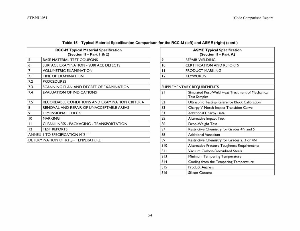
STP-NU-051 Code Comparison Report
54
Table 15—Typical Material Specification Comparison for the RCC-M (left) and ASME (right) (cont.)
RCC-M Typical Material Specification (Section II – Part 1 & 2)
ASME Typical Specification (Section II – Part A)
5 BASE MATERIAL TEST COUPONS 9 REPAIR WELDING 6 SURFACE EXAMINATION - SURFACE DEFECTS 10 CERTIFICATION AND REPORTS 7 VOLUMETRIC EXAMINATION 11 PRODUCT MARKING 7.1 TIME OF EXAMINATION 12 KEYWORDS 7.2 PROCEDURES 7.3 SCANNING PLAN AND DEGREE OF EXAMINATION SUPPLEMENTARY REQUIREMENTS 7.4 EVALUATION OF INDICATIONS S1 Simulated Post-Weld Heat Treatment of Mechanical
Test Samples 7.5 RECORDABLE CONDITIONS AND EXAMINATION CRITERIA S2 Ultrasonic Testing-Reference Block Calibration 8 REMOVAL AND REPAIR OF UNACCEPTABLE AREAS S3 Charpy V-Notch Impact Transition Curve 9 DIMENSIONAL CHECK S4 Additional Charpy Data 10 MARKING S5 Alternative Impact Test 11 CLEANLINESS - PACKAGING - TRANSPORTATION S6 Drop-Weight Test 12 TEST REPORTS S7 Restrictive Chemistry for Grades 4N and 5 ANNEX 1 TO SPECIFICATION M 2111 S8 Additional Vanadium DETERMINATION OF RTNDT TEMPERATURE S9 Restrictive Chemistry for Grades 2, 3 or 4N S10 Alternative Fracture Toughness Requirements S11 Vacuum Carbon-Deoxidized Steels S13 Minimum Tempering Temperature S14 Cooling from the Tempering Temperature S15 Product Analysis S16 Silicon Content
Code Comparison Report STP-NU-051
55
4.5 Design Highlights
• Different limits and rules of reinforcement approach for vessel openings in RCC-M (RCC-M Appendix ZA and through finite element analysis).
• RCC-M requirements for additional justification for Class 1 vessel Stress Classification; generally, RCC-M C 3000 table can be used.
• Some differences in allowable stresses, in particular associated to nonlinear analysis.
• Differences in fatigue analysis, such as differences in strain correction factor Ke or crack-like defect analysis.
• Differences in rupture analysis, larger scope and more detail analysis in RCC-M (in accordance with RCC-M Appendix ZG, more prescriptive than ASME III Appendix G).
This part covers the sections on design of the two codes: these are Section 3000 of the Volume B in Tome I of the RCC-M Code and the Chapter 3000 of Section III Division 1 Subsection NB of the ASME Code.
RCC-M has a specific volume for small components (vessels, piping, pumps and valves under a certain pressure, and certain sizes): Volume E. There is no similar Chapter in ASME III.
These parts covering design are overall quite comparable as far as the restrictions, stress limits and even wording of the paragraphs. Table 16 draws a parallel between the organizations of these two codes and this makes the comparison relatively straightforward.
As far as the contents are concerned, some similarities are obvious. For instance, the general stress analysis philosophy also is the same: both are based on stresses calculated using elastic calculations and the Tresca Stress Intensity as a yield criterion. Both codes also require the write-up of a stress report to demonstrate the compliance of the design to the requirements. But the part of interest for this report, and the rest of this section, is the differences between the codes.
The first difference that will be addressed here is the reinforcement of openings. A second part will then present how the stresses are classified in both codes and a third section will make a comparison between the categories dealt with. Finally, a deeper insight of fatigue analysis will be given in a fourth paragraph.
First, concerning the openings in the vessel wall, the approach between the two codes is quite different. As stated in the ASME Code, there are clear mandatory rules to follow when it comes to design openings in vessels and especially how to reinforce them to facilitate the stress analysis. A reinforced opening as per ASME Section III, Division 1, NB-3334 will typically not require a detailed calculation of the stresses outside a so-called Limit of Reinforcement. This limit defines a zone where a sufficient amount of material that was taken away from the vessel when punching the opening has been compensated for on either side of the opening. In practice, calculations using the classic Continuum Mechanics equations will be sufficient to demonstrate the compliance of the opening to the ASME rules for all or simple nozzle designs. It is not fully adapted for modern nozzle designs that are more “progressive” and “smoother” than previous designs.
Conversely, in the RCC-M Code, these rules are stated in the non-mandatory appendices (Appendix ZA). The reinforcement of openings for design is an indication that may or not be followed. In practice, this will translate in an additional effort in analysis and calculations to obtain a more optimized design.
STP-NU-051 Code Comparison Report
56
It is important to note at this point that with modern types of nozzles, for instance, with the smooth transition profiled nozzles fabricated with an extrusion process versus the former welding of the nozzle on the vessel, it has become more and more difficult to apply the Limit of Reinforcement rules from the ASME. The RCC-M Code, by shifting the Limit of Reinforcement method to the non-mandatory appendix, demonstrates an evolution to incorporate rules for this modern type of nozzle, which offers better design
In addition, although the general design philosophy is comparable, another difference lies in the stress classification. In both codes, the calculated stresses are first organized in various categories depending on the nature of the stress. As an example, a stress due to a pressure inside a recipient will not be of a same nature as a stress due to temperature effects and hence requires a classification system. The ASME BPVC is very instructive about this classification and gives numerous examples and even tables illustrating this classification (Section III Division 1, paragraphs NB-3217-1 and NB-3217-2).
The RCC-M Code is much less explicit and even states that “In case of doubt, the damage mechanisms must be considered when resolving the practical problems presented by these operations.” (RCC-M Tome I, Section B-3231.1). In practical applications, the RCC-M C 3000 table can be used (not mentioned in the 2007 Code Edition). What can seem like a minor discrepancy may have a significant impact in practice: when presenting the stress analysis work, the analyst will be expected to present at least a small explanation of the stress classification methodology used. This will force the analyst to fully master and comprehend the analysis techniques retained (this last point is required by QA; the analyst has to be familiar with the Code background, in particular for Class 1 components).
Concerning the levels of analysis and the criteria to be applied for each service level, see Table 17. The first difference is that the acceptance criterion for Level B is equivalent to that for the Level 0 criterion in the RCC-M 2007, which is more conservative. It should be noted here that Level B has been added in versions of the RCC-M issued from 2007 onwards.
The ASME Code gives slightly more stringent criteria for the Design Limits, especially concerning the membrane plus bending stress limits, as can be read in ASME Section III Division 1 NB-3221.3.
Concerning the Collapse Load analysis found in ASME Section III Division 1, NB-3228.1 and NB-3228.2, and RCC-M Tome I Sections B-3241 and B-324, both codes permit the use of limit (elastic-perfectly plastic) analysis or experimentation to determine the lower-bound collapse load, as an alternate method to satisfying the requirements for some primary stress limits. But the ASME Code, being more restrictive, requires the use of 1.5Sm for the yield strength in an analysis, while the RCC-M permits the use of the yield strength. The ASME Code permits the use of two-thirds collapse load as an alternative for satisfying the Design Condition stress limits for General Primary Membrane Stress, Pm (NB-3221.1), Local Primary Membrane Stress, PL (NB-3221.2) and Primary Membrane (PL or Pm) plus Bending Stress (Pb) (NB-3221.3). The RCC-M allows the use of two-thirds collapse load as determined by alternate analysis or testing in place of satisfying only Level 0 PL (B-3233.2) and PL or Pm + Pb (B-3233.3) stress limits. Both codes allow similar use of collapse load limits for Level C, Level D, and Test, for external pressure.
Both the ASME and RCC-M permit the use of alternative analysis using actual material stress-strain relationships (plastic) analysis or experimentation to determine the plastic analysis collapse load, as an alternate method to satisfying the requirements for some primary stress limits (PL or Pm + Pb). For the Design Condition, ASME Section III Division 1 NB-3228.3 allows use of two-thirds the plastic collapse load, while the RCC-M Tome I Section B-3243 limits the Level 0 loading to 0.4 times the instability load. The Level C limit is 120% (0.5 times the instability load) of Level 0 or the Design Condition, and Level D and Test limits are similar.
Code Comparison Report STP-NU-051
57
Turning to Level A Service Loadings and fatigue analysis, a first significant difference is the definition of the Ke factor (see detailed table in appendix, line NB 3222). When the stress range in fatigue analysis exceeds the given allowable (3Sm, as given in ASME Section III Division 1, NB-3228.5 and RCC-M Tome I Section B-3234.3), both codes permit the calculation of a strain correction factor Ke in consideration of a simplified elastic-plastic analysis (NB-3228.5 and B 3234.6), but the formulae to calculate this factor are different.
For austenitic steels as well as the nickel-chromium-iron alloys, the RCC-M has separate expressions for the calculation of Ke for the mechanical contribution to the stress range and the thermal contribution to the stress range. The ASME, overly conservative, uses the same expression for the combined mechanical and thermal stress range. This implies a noticeable difference in practice for fatigue results for austenitic steels as well as the nickel-chromium-iron alloys. Figure 20 shows the corresponding curves for the Ke values. See Figure 20 for illustration of these differences.
Still concerning Level A criteria, the RCC-M Tome I Section B-3234.7 gives advice about any geometrical discontinuity and indicates special finite element modeling requirements in Appendix ZD. The latter contains a method on how to analyze geometrical singularities.
The ASME, on the other hand, specifies Strength Reduction Factors, defined NB-3213.17, to address fatigue crack initiation: ASME NB-3252.4 (d-5) indicates, for instance, that a Strength Reduction Factor of no less than 4 should be used. If no factor is specified in the Owner Design Specification, the ASME leaves it to the analyst’s discretion to make the decision with the associated justifications. See Table 18 for factor of safety comparison between the two codes.
Turning to fracture analysis, both the ASME Code (NB-3211, Appendix G) and RCC-M (B 3260, Appendix ZG) require an evaluation of the vessel design for protection against fracture. The ASME Code focuses on nonductile failure of ferritic materials, while the RCC-M examines both ductile and nonductile fracture, for austenitic or austenitic-ferritic materials, and ferritic materials, respectively.
Except for Class 1 reactor pressure shells, the RCC-M provides exemptions from evaluation based on material properties.
The second level is based on large reference defects. Postulated flaws applied in the evaluations are similar between the two codes (except for RCC-M, where the maximum flaw depth is 20 mm instead of 1/4 t in ASME, including thick wall). For thick vessels, 1/4 wall thickness with a width to length ratio of 1/6 is used, except near nozzle corners for the RCC-M, where the width to length ratio of 1/2 is prescribed. The RCC-M requires the crack center, as well as the ends, to be evaluated. Examinations for the ASME Code are based on crack tip stress intensity, KI, while the RCC-M requires examination of either crack tip stress intensity, Kcp (elastic KI plus plasticity effect correction factor), or crack extension force, J, for the ductile evaluation. All the detailed formulae for elastic Ke evaluation of all locations are attached to RCC-M through RSE-M Appendix 5; nothing similar is available in ASME III Code. Particular attention is required on dissimilar-metal welds in RCC-M (methods and data are analyst responsibilities); nothing similar is available in ASME III Code.
Both codes allow for a conservative simple calculation method and a more detailed calculation method, when the simple evaluation is too conservative.
The detailed methods are similar to some extent, but more detailed for the RCC-M. RCC-M provides simple conservative rules for consideration of the plastic zone at the crack tip.
If exemption rules and reference large defect criteria cannot exceptionally be fulfilled, RCC-M permits the detailed methods of determining flaw size based on in-service crack monitoring (RSE-M, Appendix 5.4) with an associated pre-service inspection of the location.
STP-NU-051 Code Comparison Report
58
The ASME allows the use of the Welding Research Council Bulletin WRCB-175 for determination of the critical flaw size, which also considers the effect of the plastic zone at the crack tip, but only when WRCB-175 is to be applied.
The critical stress intensity factor, KIC, used as an acceptance criterion for flaw size, is based on static initiation fracture toughness obtained under slow loading conditions for both codes.
Factors of Safety to be applied for Level A-B service levels are nearly the same but the ASME Code does not require any factors for Level C and D. Both codes require the effects of irradiation on the fracture toughness to be considered, but the RCC-M also prescribes methods for consideration, as well as consideration of thermal aging and strain aging (that are mainly used during periodic safety review of existing plants).
Overall, the ASME Code has a limited scope, based on simple assumptions (some are conservative, some are not, some are based on very old data and so on) with respect to design, while the RCC-M is more prescriptive and detailed with respect to analytical requirements and provides an increased understanding of margins.
Both codes use their design methods for Pressure-Temperature limits of PWR in Operation.
RSE-M uses the reference defect analysis and margins to define its In-Service-Inspection program: this justifies the need of “realistic and conservative” methods and data to reach an understanding of the margins. Today, analyses of all Class 1vessel welds and cast materials are systematically required by different regulators or different owner design specifications. RCC-M answers to these latest requirements; ASME BPVC Section III needs more investment of the analyst in terms of methods and material properties. Many important decisions on this “rupture” topic have to be made quite early in the design of new plants to ensure safety and optimum operation.
Finally, both the ASME and RCC-M permit the use of alternative analysis using actual material stress-strain relationships (plastic) analysis to evaluate for progressive deformation under cyclic loading, as an alternate method to satisfying the requirements for thermal stress ratchet (NB-3222.5 or B 3234.8) and progressive distortion of non-integral connections (NB-3227.3 or B 3238.3). Either code allows plastic analysis strain range results to be applied in the fatigue analysis, in determining the alternating stress. The ASME Code is less restrictive as it allows exemptions from shakedown analysis for ductile materials.
To sum up, one main conclusion is that the requirements from the two codes are similar as far as the methods for primary stress evaluation as well as regards allowable limits.
The RCC-M nevertheless includes more experience feedback for the analysis related to two major failure modes: fatigue and fracture, that need more state-of-the-art methods and data, in order to reach a better understanding of margins and take decisions early in the design process of new plants or components. This detailed understanding of margins is also important for the definition of an optimum In-Service Inspection program.
4.5.1 Piping, Valves and Pumps Highlights:
• Major differences for pumps, valves and piping are associated to design rules; the principles for material selection, fabrication-welding and control are extremely similar between vessel and piping, pumps and valves
• Design report is required for DN 100 or over in ASME III, and DI 25mm and over in RCC-M
• RCC-M proposes to use B 3300 and B 3200 to design piping, pumps and valves; ASME III proposes to use only NB 3300
Code Comparison Report STP-NU-051
59
• No fatigue exemption rules in RCC-M, but as for vessels optimized fatigue analysis rules, supplemented by a particular piping fatigue analysis appendix (Appendix ZE)
• For pumps, the RCC-M scope is more limited than ASME III in pump types;
• For valves, a particular body shape rules for internal radius is proposed by RCC-M for fatigue sensitive valves
• For piping, the level A criteria (equation 10), the stress indices and the seismic criteria are different between RCC-M B 3600 and ASME III NB 36000.
4.5.1.1 Pumps
For Pumps, the scope of RCC-M B 3400 and ASME III NB 3400 are very similar.
The small pumps less than 165 KW are covered by a particular sub-section E in RCC-M, no small pumps (DN < 100) are considered in ASME III.
The RCC-M scope is limited to centrifugal/single volute casing pumps and ASME III considers more different types of pumps.
The design requirements are similar for both codes: ASME III NB 3350 or RCC M B 3350, RCC-M accept the use of B 3200 instead of B 3300; more severe requirements in RCC-M to consider external loads (Peb) than ASME III; same differences than vessels for fatigue analysis (Ke optimization and crack like defects) and rupture analysis.
For bolting the rules are similar.
For support ASME III proposes subsection NF and RCC-M subsection H, which are similar.
Design report is required for DN 100 or over in ASME III, and DI 25mm in RCC-M
4.5.1.2 Valves
The scopes are similar (no particular rules for pressure relieve valves in RCC-M), but RCC-M does not cover bellows, springs and diaphragms; the ratings are limited in RCC-M to PWR operating conditions, larger number of ratings in ASME III; same as for pumps: B 3300 is proposed (+ B 3200 for RCC-M), design report is required for DN 100 or over in ASME III, and DI 25mm in RCC-M.
One difference in body shape rules for valves sensitive to thermal fatigue: r3 is limited to 0.05tm (fig. NB 3544.1(c)-1) in ASME III NB 3500 and 0.1 Tr (fig. B 3544.1.b) in RCC-M B 3500.
Same differences than vessels for fatigue analysis (Ke optimization and crack like defects) and rupture analysis.
4.5.1.3 Piping
The scopes are similar and the differences very similar to pumps and valves (no miters and no non- welded piping joints in RCC-M).
The complementary differences are:
• In level C, the ASME III NB 3600 criteria is 2.25Sm instead of 1.9Sm in RCC-M B 3600
• In level A, ∆T1 is included in RCC-M equation (10) not in ASME III 2007 (it was in the past ASME editions); but the Ke is more realistic in RCC-M than in ASME III for fatigue analysis (see figure 4.5.1)
• No fatigue analysis exemption rules for class 1 piping in RCC-M
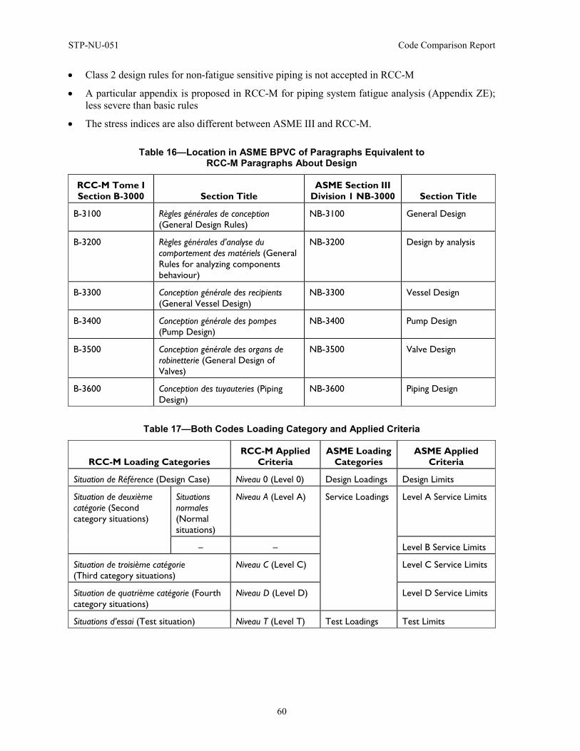
STP-NU-051 Code Comparison Report
60
• Class 2 design rules for non-fatigue sensitive piping is not accepted in RCC-M
• A particular appendix is proposed in RCC-M for piping system fatigue analysis (Appendix ZE); less severe than basic rules
• The stress indices are also different between ASME III and RCC-M.
Table 16—Location in ASME BPVC of Paragraphs Equivalent to RCC-M Paragraphs About Design
RCC-M Tome I Section B-3000 Section Title
ASME Section III Division 1 NB-3000 Section Title
B-3100 Règles générales de conception (General Design Rules)
NB-3100 General Design
B-3200 Règles générales d’analyse du comportement des matériels (General Rules for analyzing components behaviour)
NB-3200 Design by analysis
B-3300 Conception générale des recipients (General Vessel Design)
NB-3300 Vessel Design
B-3400 Conception générale des pompes (Pump Design)
NB-3400 Pump Design
B-3500 Conception générale des organs de robinetterie (General Design of Valves)
NB-3500 Valve Design
B-3600 Conception des tuyauteries (Piping Design)
NB-3600 Piping Design
Table 17—Both Codes Loading Category and Applied Criteria
RCC-M Loading Categories RCC-M Applied
Criteria ASME Loading
Categories ASME Applied
Criteria
Situation de Référence (Design Case) Niveau 0 (Level 0) Design Loadings Design Limits
Situation de deuxième catégorie (Second category situations)
Situations normales (Normal situations)
Niveau A (Level A) Service Loadings Level A Service Limits
– – Level B Service Limits
Situation de troisième catégorie (Third category situations)
Niveau C (Level C) Level C Service Limits
Situation de quatrième catégorie (Fourth category situations)
Niveau D (Level D) Level D Service Limits
Situations d’essai (Test situation) Niveau T (Level T) Test Loadings Test Limits
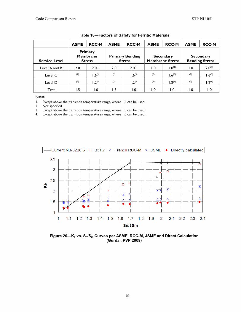
Code Comparison Report STP-NU-051
61
Table 18—Factors of Safety for Ferritic Materials
ASME RCC-M ASME RCC-M ASME RCC-M ASME RCC-M
Service Level
Primary Membrane
Stress Primary Bending
Stress Secondary
Membrane Stress Secondary
Bending Stress
Level A and B 2.0 2.0(1) 2.0 2.0(1) 1.0 2.0(1) 1.0 2.0(1)
Level C (2) 1.6(3) (2) 1.6(3) (2) 1.6(3) (2) 1.6(3)
Level D (2) 1.2(4) (2) 1.2(4) (2) 1.2(4) (2) 1.2(4)
Test 1.5 1.0 1.5 1.0 1.0 1.0 1.0 1.0
Notes: 1. Except above the transition temperature range, where 1.6 can be used. 2. Not specified. 3. Except above the transition temperature range, where 1.3 can be used. 4. Except above the transition temperature range, where 1.0 can be used.
Figure 20—Ke vs. Sn/Sm Curves per ASME, RCC-M, JSME and Direct Calculation (Gurdal, PVP 2009)
STP-NU-051 Code Comparison Report
62
4.6 Fabrication – Welding Highlights
• To qualify a material manufacturer process per RCC-M, a qualification piece is required before fabrication for components listed in M 141 & M 160 in Section II.
• Test coupons required even after welding qualification in the RCC-M.
• Brazing is not covered in RCC-M, nor is capacitor discharge welding.
• Attachments and appurtenances for welding are dealt with in detail in ASME.
• Friction welding is not covered in ASME.
• Hubbed flanges are not covered in RCC-M for Class 1 equipment.
• Cleanliness requirements during fabrication and assembly are covered in RCC-M Section III F-6000 and are under owner responsibility in ASME.
• The differences of format and documentation requirements can lead to deviation in front of each national authority, although the manufacturing processes are similar in the two codes.
This part covers the differences in welding and fabrication. These parts are dealt with separately in the RCC-M but overlap in the ASME. They have been grouped together in one section here but will be addressed in two paragraphs.
Welding is included in Section IV of the RCC-M Code and the equivalent provisions can be found in parts of Section III Division 1 NB paragraphs and parts of Section IX of the ASME BPVC.
This part begins with differences in welding qualifications. A second paragraph will then highlight how different the weld processes are, and finally, a third section will analyze the weld examination methods.
Concerning the weld and welding process qualification, the RCC-M stipulates that the ISO norms should be followed. Turning to Section IV Section S-3200 for instance, a foreword indicates that the rest of the section will be in accordance with the prescriptions from the norm NF EN ISO 15614-1. In the following paragraphs, the numbering is virtually the same as in the norm. It should nevertheless be noted here that additional requirements exist in the RCC-M and that may not be found in the norm. In the ASME, the welds and welding process qualification should be done as per Section IX and additional provisions specific to the nuclear industry in Section III.
ASME and RCC-M have a similar approach of PQR and WP. The manufacturer or contractor, as stated respectively in Section IX QW 200.2 in ASME or in quality assurance management requirements in Section I A-5000 in RCC-M, reviews and certifies Procedure of Qualification Record (PQR) and Welding Procedures (WP). The RCC-M requires in Section I, Sections ZZ-400 and ZY-400 that a Notified Body reviews the WP or PQR (Appendix 1 – line NB-4310).
Finally, to conclude this paragraph, and concerning documentation for welding in general, it has to be noted that the format of documentation is different in ASME and RCC-M for PQR and WPS, even if the process is identical in itself and differs only by a few parameters. As an example, first taking the RCC-M Section IV S-3150, there is a list of reports to provide to approve the welding procedure qualification. One of these relates to the acceptance of filler material. The code then refers to Section IV S-2000 and gives in S-2800 and S-2900 reference data sheets for filler material. This reference is interesting because, although it appears not to be compulsory to strictly follow this layout, it provides an example of a typical data sheet in the RCC-M Code philosophy. An example of this sheet necessary in the Welding Procedure Qualification can be seen in Figure 21.
Code Comparison Report STP-NU-051
63
On the other hand, the Welding Qualification Procedure is provided in detail in the ASME BPVC Section IX QW 200.2. In this part, it refers to a series of reference non-mandatory documents located in Section IX Non-mandatory Appendix B. An example of one sheet is given Figure 22.
Both codes include welding techniques that the other code does not deal with and/or designates as prohibited. The first example is friction welding: it is excluded from use for pipes in the ASME BPVC Section III Division 1 NB-4311.4 but allowed in the RCC-M Code (Appendix 1 – line NB-4311). An interesting account of a practical example of how the gap was bridged to qualify friction welding in the U.S. is given in Reference [3]. This consists of a practical example of a component manufactured in France but destined to the American market.
On the other hand, the ASME BPVC mentions capacitor discharge welding in Section III Division 1 NB-4311.2, whereas this process is not mentioned anywhere in the RCC-M (Appendix 1 – line NB-4311).
Finally, the ASME BPVC has dedicated a whole paragraph to brazing, Section III Division 1 NB-4500. This process can essentially be used, as specified by the ASME BPVC, for attachment of cladding to the base material and of tubes to tubesheets. Appurtenances and piping filling specific criteria may be brazed also (Appendix 1 – line NB-5000). This process is not dealt with in the RCC-M and for the previous example, the manufacturing processes used are described in Section IV S-3600 and S-3700.
Finally, RCC-M can be more conservative when it comes to examination of the weld. A first example is for volumetric examination of ferritic welds in Class 1 components: RCC-M Section IV Section S-7713.2 specifies that such examination requires the use of radiographic and ultrasonic techniques while the ASME Section III Division 1 Section NB 4400 does not include such a requirement (Appendix 1 – line NB-4400).
Furthermore, and comparing the preparation of the test coupons and specimens dealt with in ASME Section III Division 1 Section NB 4334 and in the RCC-M Section IV S-3000, it can be seen that the tests are different. First, the RTNDT is not required for all materials in RCC-M, whereas it is required for all materials in ASME. On the other hand, chemical analysis is required in RCC-M but not in ASME (Appendix 1 – line NB 4334).
In addition, RCC-M permits no undercut as can be seen in RCC-M Section IV, Sections S-7460 and S-7714 for Class 1 and 2 welds. On the other hand, ASME Section III, Section NB-4424.1 permits 1/32 inch. (1 mm). This stems from the fact that the French authorities have identified undercuts as being a potential cause for weld failure (Appendix 1 – line NB-4334).
Moreover, multiple test coupons are to be taken as instructed in RCC-M Section IV, Section S-7800. For the most part of the equipment manufactured, test coupons will be necessary to demonstrate the know-how of welders but also necessary for every Weld Procedure Specification (WPS) and component, even after a welding procedure has been qualified. On the other hand, the ASME does not require so many test coupons after the qualification of the welding procedure. ASME will typically rely in practice on manufacturer work under survey of a third party (either ANI or AIA).
Fabrication is mentioned in Section I of the RCC-M but most of the instructions related to fabrication are included in Section V. It should also be noted that Section II Section M-100 includes some requirements related to pre-qualification of equipment before “mass production.” The Fabrication and Installation paragraphs can all be found in Section III of the ASME. Table 4.3.3.2 below presents the layout comparison between the two codes.
Both codes contain a first section on the pre-fabrication stage. The next paragraph lists in more detail the discrepancies related to the fabrication part itself.
STP-NU-051 Code Comparison Report
64
The RCC-M states in Section II M-140 that a qualification is necessary for material or part supplier of a component in the list M-141, thereby requiring the workshop to forge the first piece to demonstrate its capability to complete the task, monitoring all parameters of forging while doing so. For future pieces, it is not necessary to demonstrate the monitoring of all the same parameters, if the manufacturer has already been qualified as per the RCC-M to produce parts and can demonstrate continuity in competencies. This process philosophy from the RCC-M is based on evidence of monitoring the right production parameters by the part manufacturer. After the successful completion of the qualification piece, the batch of equipment can be produced, but only within the limits defined by the qualification piece. Overall, RCC-M aims at providing evidence on actual material for the qualification piece. It should be noted that, depending of the country of regulation, a third party will be mandatory, in addition to RCC-M requirements. Concerning the so-called qualification piece or “prototype,” it should be highlighted here that it should be treated as a first-of-a-kind type part, does not have to be scrapped, and can be used industrially as long as it shows the adequate level of quality.
On the other hand, the ASME BPVC considers that a qualified supplier has knowledge that allows manufacture of parts, validated through the following approach.
• Qualification program and certification (NCA 3800, for example) of the material producer • Mandatory procurement specification taking into account owner and designer requirements • Acceptance by third party (ANI or AIA) of final forged part for integration in equipment
If the Designer orders a part correctly, a third party (ANI or AIA) will check that the performance specified for the part manufacturing is adequate, with the right implementation of the know-how of the manufacturer.
Concerning the Fabrication itself, the RCC-M is, overall, more prescriptive than the ASME and this can be illustrated by the following examples.
First, the RCC-M lays down very stringent steps to follow concerning the forming, bending and cutting. Documentation is necessary (Section V F-4112), the qualification process and tests follow a very detailed process (Section V F-4120), and the results of the qualification can be subject to examination by Inspectors (Section V F-4126).
The RCC-M has grouped all experience feedback related to cleanliness in a dedicated section of the code, Section V Section F-6000. The ASME BPVC does not have an equivalent section pertaining to cleanliness requirements. Part of basic cleanliness requirements can be found in various sections of the ASME BPVC, such as Section III Division 1 NB-4412, pertaining to Cleanliness and Protection of Welding Surfaces (Appendix 1 – line NB-4412). The RCC-M Code is particularly stringent on this aspect and it forces the workshop to have an irreproachable cleanliness to manufacture components for the nuclear industry. The ASME BPVC tends to consider implicitly this aspect as the responsibility of the owner.
Finally, Section V F-5000 of the RCC-M deals with surface treatment as a whole. It encompasses various domains ranging from cladding to painting. The ASME BPVC has, for instance, information pertaining to cladding in Section III Division 1 NB-4000 and in Section IX. However, no section dedicated specially to surface treatment can be found in the ASME BPVC, leaving the user to juggle between the different sections to identify the mandatory requirements.
While the ASME permits the use of fabricated hubbed flanges as specified in Section III Section NB-2125, they are excluded from use for Class 1 equipment in the RCC-M, as specified in Section I Appendix Z-V (Appendix 1 – line NB-2125).
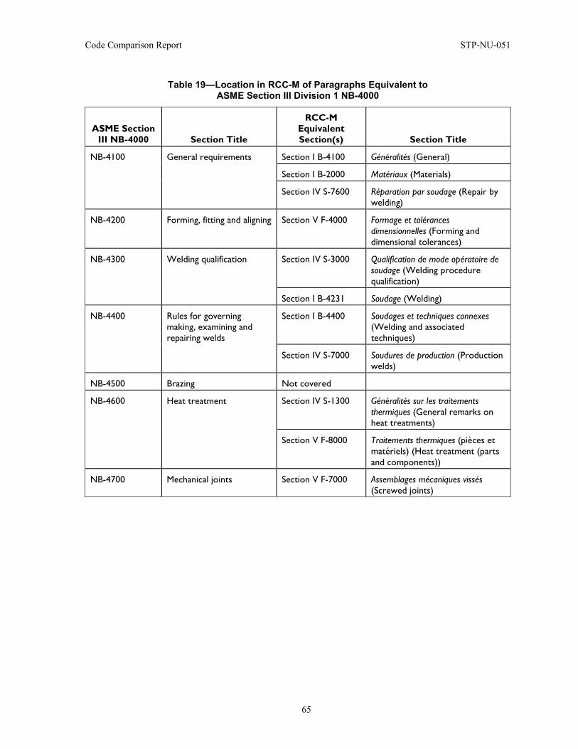
Code Comparison Report STP-NU-051
65
Table 19—Location in RCC-M of Paragraphs Equivalent to ASME Section III Division 1 NB-4000
ASME Section III NB-4000 Section Title
RCC-M Equivalent Section(s) Section Title
NB-4100 General requirements Section I B-4100 Généralités (General)
Section I B-2000 Matériaux (Materials)
Section IV S-7600 Réparation par soudage (Repair by welding)
NB-4200 Forming, fitting and aligning Section V F-4000 Formage et tolérances dimensionnelles (Forming and dimensional tolerances)
NB-4300 Welding qualification Section IV S-3000 Qualification de mode opératoire de soudage (Welding procedure qualification)
Section I B-4231 Soudage (Welding)
NB-4400 Rules for governing making, examining and repairing welds
Section I B-4400 Soudages et techniques connexes (Welding and associated techniques)
Section IV S-7000 Soudures de production (Production welds)
NB-4500 Brazing Not covered
NB-4600 Heat treatment Section IV S-1300 Généralités sur les traitements thermiques (General remarks on heat treatments)
Section V F-8000 Traitements thermiques (pièces et matériels) (Heat treatment (parts and components))
NB-4700 Mechanical joints Section V F-7000 Assemblages mécaniques vissés (Screwed joints)
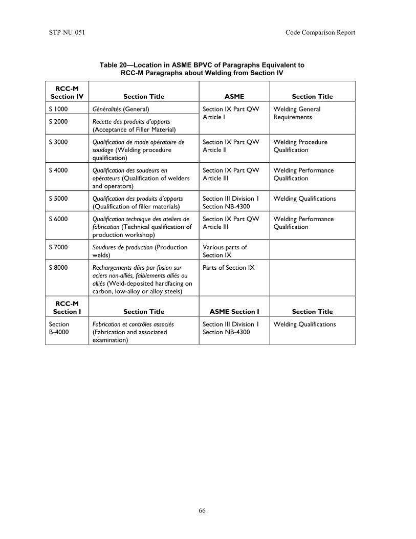
STP-NU-051 Code Comparison Report
66
Table 20—Location in ASME BPVC of Paragraphs Equivalent to RCC-M Paragraphs about Welding from Section IV
RCC-M Section IV Section Title ASME Section Title
S 1000 Généralités (General) Section IX Part QW Article I
Welding General Requirements
S 2000 Recette des produits d’apports (Acceptance of Filler Material)
S 3000 Qualification de mode opératoire de soudage (Welding procedure qualification)
Section IX Part QW Article II
Welding Procedure Qualification
S 4000 Qualification des soudeurs en opérateurs (Qualification of welders and operators)
Section IX Part QW Article III
Welding Performance Qualification
S 5000 Qualification des produits d’apports (Qualification of filler materials)
Section III Division 1 Section NB-4300
Welding Qualifications
S 6000 Qualification technique des ateliers de fabrication (Technical qualification of production workshop)
Section IX Part QW Article III
Welding Performance Qualification
S 7000 Soudures de production (Production welds)
Various parts of Section IX
S 8000 Rechargements dûrs par fusion sur aciers non-alliés, faiblements alliés ou alliés (Weld-deposited hardfacing on carbon, low-alloy or alloy steels)
Parts of Section IX
RCC-M Section I Section Title ASME Section I Section Title
Section B-4000
Fabrication et contrôles associés (Fabrication and associated examination)
Section III Division 1 Section NB-4300
Welding Qualifications
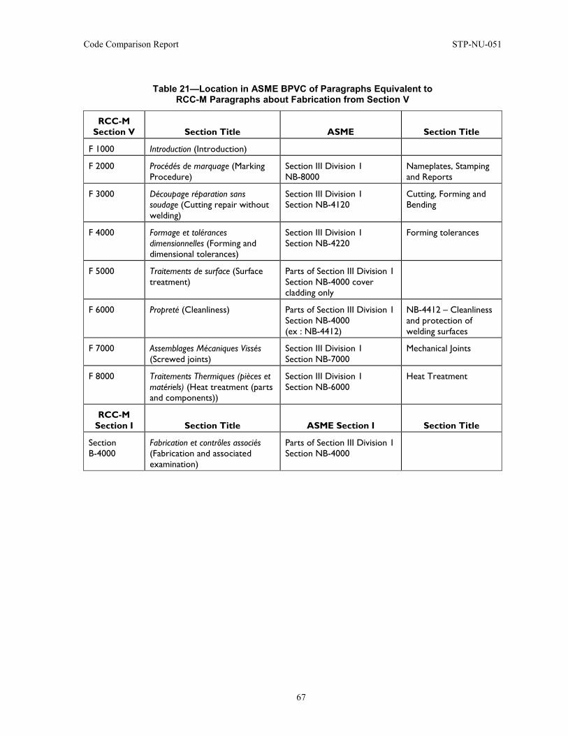
Code Comparison Report STP-NU-051
67
Table 21—Location in ASME BPVC of Paragraphs Equivalent to RCC-M Paragraphs about Fabrication from Section V
RCC-M Section V Section Title ASME Section Title
F 1000 Introduction (Introduction)
F 2000 Procédés de marquage (Marking Procedure)
Section III Division 1 NB-8000
Nameplates, Stamping and Reports
F 3000 Découpage réparation sans soudage (Cutting repair without welding)
Section III Division 1 Section NB-4120
Cutting, Forming and Bending
F 4000 Formage et tolérances dimensionnelles (Forming and dimensional tolerances)
Section III Division 1 Section NB-4220
Forming tolerances
F 5000 Traitements de surface (Surface treatment)
Parts of Section III Division 1 Section NB-4000 cover cladding only
F 6000 Propreté (Cleanliness) Parts of Section III Division 1 Section NB-4000 (ex : NB-4412)
NB-4412 – Cleanliness and protection of welding surfaces
F 7000 Assemblages Mécaniques Vissés (Screwed joints)
Section III Division 1 Section NB-7000
Mechanical Joints
F 8000 Traitements Thermiques (pièces et matériels) (Heat treatment (parts and components))
Section III Division 1 Section NB-6000
Heat Treatment
RCC-M Section I Section Title ASME Section I Section Title
Section B-4000
Fabrication et contrôles associés (Fabrication and associated examination)
Parts of Section III Division 1 Section NB-4000
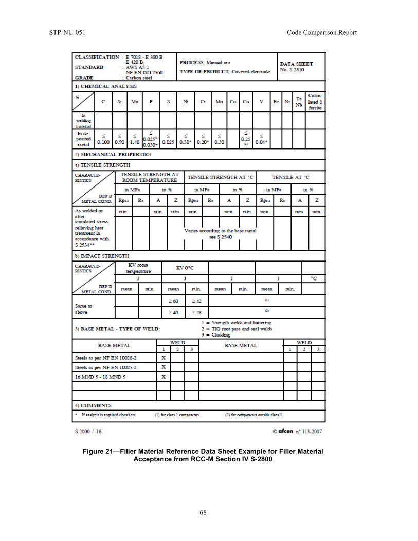
STP-NU-051 Code Comparison Report
68
Figure 21—Filler Material Reference Data Sheet Example for Filler Material Acceptance from RCC-M Section IV S-2800
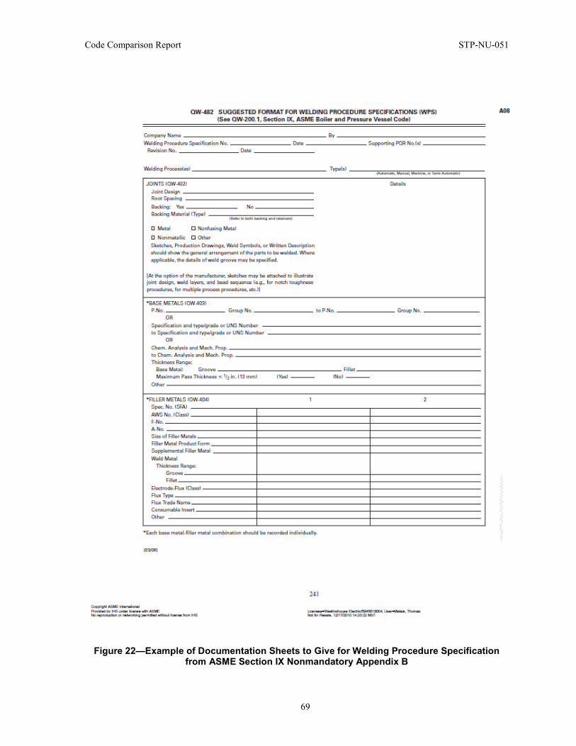
Code Comparison Report STP-NU-051
69
Figure 22—Example of Documentation Sheets to Give for Welding Procedure Specification from ASME Section IX Nonmandatory Appendix B
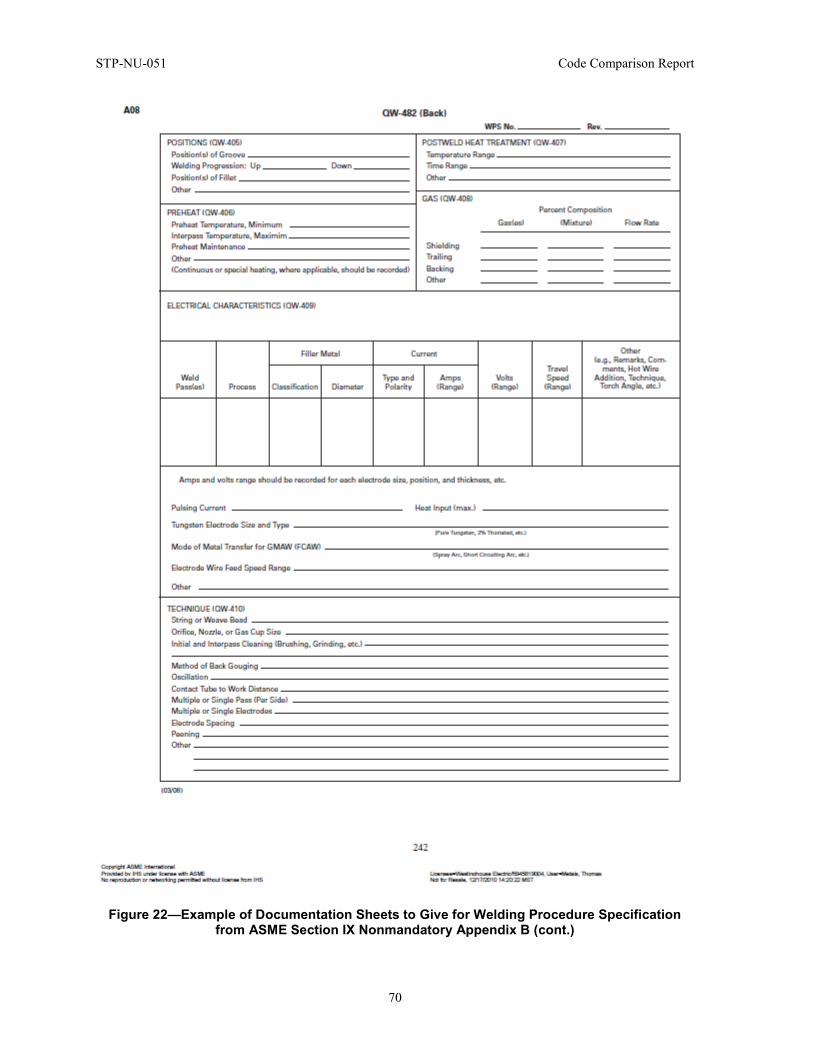
STP-NU-051 Code Comparison Report
70
Figure 22—Example of Documentation Sheets to Give for Welding Procedure Specification from ASME Section IX Nonmandatory Appendix B (cont.)
Code Comparison Report STP-NU-051
71
4.7 Examination Highlights
• RCC-M personnel qualification must preferably follow European Standard but any equivalent specification can be admitted; ASME refers to U.S. standards (SNT-TC-1A).
• Existence of differences in examinations techniques and methods between ASME and RCC-M.
• ASME Section III considers pre-service examinations in accordance with Section XI requirements, while RCC-M allows owners requirements for pre-service examination.
Examination methods are addressed Section III of the RCC-M and Section V of the ASME BPVC. The RCC-M refers to examination in its Section I but, in Subsection A, essentially refers and instructs the user to look into Section III for the documentation relating to examination. The other Subsections of Section I (B, C and D), for the examinations associated to manufacturing, refer to Section IV Welding.
ASME Section III includes in its Division 1 Section NB-5000 requirements that are unique to the nuclear industry, including specification of limits for acceptance after examination. A significant part of the information on nondestructive examination (NDE) is nevertheless concentrated in a different section, as in the RCC-M, and the latter is Section V.
It should be mentioned that both RCC-M and ASME include also provisions for NDE in their Material sections, Section II in both codes, especially about the extent, the time (stage) and acceptance criteria for the examination. Special examination requirements for welding are also included in the Section IV of the RCC-M and the Section IX of the ASME.
This section will first describe the differences in practice for NDE personnel qualification and then, in a second paragraph, focus on the differences between the techniques and methods used.
NDE personnel qualification is done per SNT-TC-1A according to the ASME Section III Division 1 NB-5510. In paragraph Section III Division 1 NB-5522, it is stated that the employer has the responsibility of the adequacy of the qualification program as well as the certification of Level I, II and III NDE personnel. This is sufficient in the U.S. to become certified by the American Society of Nondestructive Testing or ASNT.
RCC-M Section III Section MC-8000 invites the user to comply with the European norm NF EN 473. Numerous common points between the two certifications can be highlighted: three levels of certification, experience and practical examination are required to progress to upper levels, certificate expires every 5 years. The certification in Europe requires the intervention of a third party to qualify the NDE personnel. This third party must be accredited by NF EN ISO/IEC 45012 to deliver certification according to the NF EN 473 performs qualification. Outside Europe, RCC-M accepts a certification granted by an independent organization following an equivalent standard after approval by The Contractor (MC 8000). A qualification from the employer as in the U.S. is not fully equivalent in process, but the technical result is level equivalent provided the employer is fully reliable.
In addition, it should be highlighted here that the qualification from the employer in ASME BPVC is not fully equivalent to certification EN 473 delivered by a third party in Europe in the process itself, despite the fact that the levels of competencies are similar (Appendix 1 – line NB-5520).
To conclude this discussion, in practice, despite the difference highlighted above, this certification issue can be overcome. The detailed comparison work was done in Reference [3] and the conclusion was that the requirements for Inspector Certification per SNT-TC-1A and per EN 473 offer the same guarantees.

STP-NU-051 Code Comparison Report
72
The following discussion focuses on the differences between the techniques and methods presented in each of the codes.
Firstly, in RCC-M Section IV S-7363, it is mentioned that liquid penetrant examination is required for Class 1 and 2 welds before starting any welding. In ASME Section III NB-4400, no such provision can be found. Looking at this method of examination in the two codes, it can be seen that the ASME Code is very descriptive as regards the liquid penetrant examination (ASME BPVC Section V, Article 6). Moreover, the penetrant removing technique is different as well as the drying method. But as analyzed in Reference [3], this gives equivalent results in practice.
The ASME Section III Division 1 NB-5410 requires examination of the weld joints by liquid penetrant or magnetic particle in addition to carrying out all pre-service volumetric examinations (Appendix 1 – line NB-5410). The RCC-M Section I B-5240 does not call for such stringent examination after the hydrotest. The philosophy is different: instead of asking for more stringent check after the test, there exists other testing, as specified Section I B-5300, that will make any problem visible. The RCC-M requires visual examination in the case of tracking gross plasticity distortion, as per RCC-M Section I B-5520. RCC-M Section IV S-7460 requires also visual examination of Class 1 and 2 welded joints.
The RCC-M requires removal and liquid penetrant examination of all arc strikes. This examination is not required by ASME. Arc strikes are generally removed and only visually examined.
For ultrasonic examination of welds, the classification of defects as planar or non-planar is essential as a planar defect is unacceptable. For this classification, the RCC-M refers to a European standard. The ASME leaves this responsibility to the NDE personnel.
The ASME BPVC includes also a paragraph about pre-service examination, Section III Division 1 NB-5332. Conversely, it should be noted here that for the PSI, it is the AFCEN RSE-M Code that covers this and that no paragraph about this topic can be found in the RCC-M (Appendix 1 – lines NB-5280 and NB-5332). At this stage though, it is also interesting to mention that the RCC-M Code allows the use of ASME BPVC Section IX for pre-service and in-service inspection. Using the RCC-M Code does not mean that the RSE-M Code should be used exclusively for these types of inspections. For the ASME BPVC, if the component is manufactured per the ASME BPVC, it is often more challenging to switch to another code for pre-service and in-service inspection.
It should also be noted that all that relates to brazing cannot be found in the RCC-M: this includes ASME BPVC Section III Division 1 NB-5274 and NB-5370 (Appendix 1 – lines NB-5274 and NB-5370).
Finally, a last point of comparison between the codes is the acceptance criteria. Taking first the radiographic examination, it can be seen first in ASME BPVC Section III Division 1 NB-5320 that the term “indication” is used. It can refer to a gas cavity as well as an inclusion. The RCC-M distinguishes the two and provides acceptance criteria depending on the nature of the indication (Appendix 1 – line NB-5320). Table 24 gives an example of the acceptance criteria for the radiographic examination from the two codes.
Turning to the ultrasonic examination, it is possible to see that the criteria given in Section III Division 1 NB- 5330 are more or less identical to the radiographic examination criteria (Appendix 1 – line 5330). On the other hand, the RCC-M is particularly extensive about this examination as can be seen in Section IV S-7714.4.
From the two previous examples, it can be seen that the RCC-M offers a more detailed and prescriptive set of requirements. One final example deals with the magnetic particle examination. In this case, it is not as easy to conclude which of the two codes is really more restrictive. The comparison can be seen in Table 25 (Appendix 1 – line 5340).
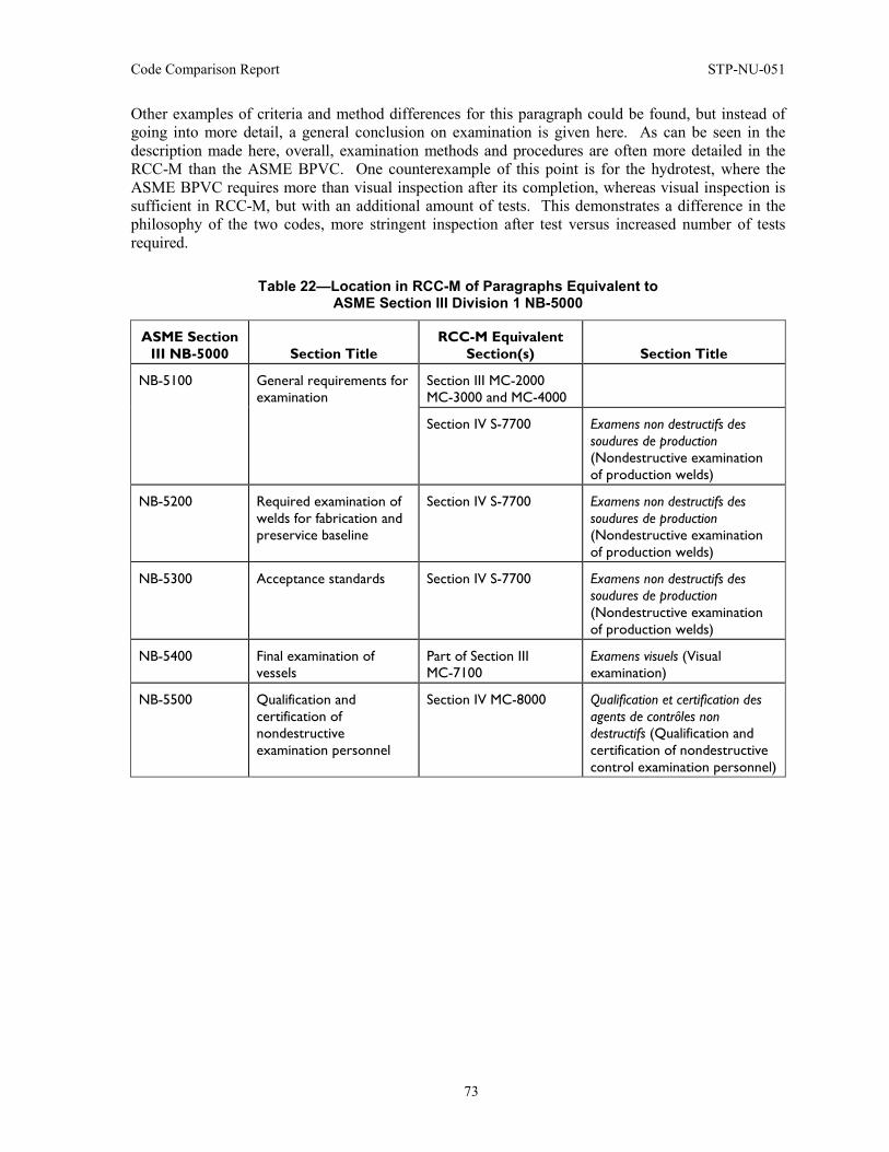
Code Comparison Report STP-NU-051
73
Other examples of criteria and method differences for this paragraph could be found, but instead of going into more detail, a general conclusion on examination is given here. As can be seen in the description made here, overall, examination methods and procedures are often more detailed in the RCC-M than the ASME BPVC. One counterexample of this point is for the hydrotest, where the ASME BPVC requires more than visual inspection after its completion, whereas visual inspection is sufficient in RCC-M, but with an additional amount of tests. This demonstrates a difference in the philosophy of the two codes, more stringent inspection after test versus increased number of tests required.
Table 22—Location in RCC-M of Paragraphs Equivalent to ASME Section III Division 1 NB-5000
ASME Section III NB-5000 Section Title
RCC-M Equivalent Section(s) Section Title
NB-5100 General requirements for examination
Section III MC-2000 MC-3000 and MC-4000
Section IV S-7700 Examens non destructifs des soudures de production (Nondestructive examination of production welds)
NB-5200 Required examination of welds for fabrication and preservice baseline
Section IV S-7700 Examens non destructifs des soudures de production (Nondestructive examination of production welds)
NB-5300 Acceptance standards Section IV S-7700 Examens non destructifs des soudures de production (Nondestructive examination of production welds)
NB-5400 Final examination of vessels
Part of Section III MC-7100
Examens visuels (Visual examination)
NB-5500 Qualification and certification of nondestructive examination personnel
Section IV MC-8000 Qualification et certification des agents de contrôles non destructifs (Qualification and certification of nondestructive control examination personnel)
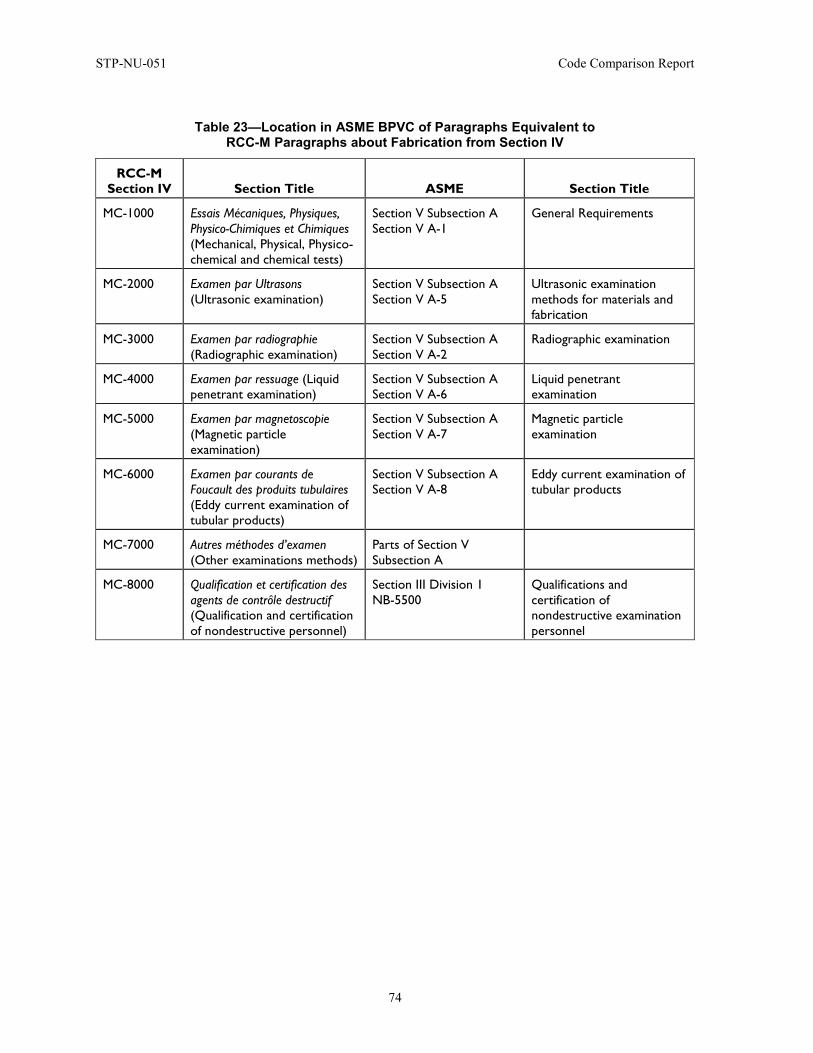
STP-NU-051 Code Comparison Report
74
Table 23—Location in ASME BPVC of Paragraphs Equivalent to RCC-M Paragraphs about Fabrication from Section IV
RCC-M Section IV Section Title ASME Section Title
MC-1000 Essais Mécaniques, Physiques, Physico-Chimiques et Chimiques (Mechanical, Physical, Physico-chemical and chemical tests)
Section V Subsection A Section V A-1
General Requirements
MC-2000 Examen par Ultrasons (Ultrasonic examination)
Section V Subsection A Section V A-5
Ultrasonic examination methods for materials and fabrication
MC-3000 Examen par radiographie (Radiographic examination)
Section V Subsection A Section V A-2
Radiographic examination
MC-4000 Examen par ressuage (Liquid penetrant examination)
Section V Subsection A Section V A-6
Liquid penetrant examination
MC-5000 Examen par magnetoscopie (Magnetic particle examination)
Section V Subsection A Section V A-7
Magnetic particle examination
MC-6000 Examen par courants de Foucault des produits tubulaires (Eddy current examination of tubular products)
Section V Subsection A Section V A-8
Eddy current examination of tubular products
MC-7000 Autres méthodes d’examen (Other examinations methods)
Parts of Section V Subsection A
MC-8000 Qualification et certification des agents de contrôle destructif (Qualification and certification of nondestructive personnel)
Section III Division 1 NB-5500
Qualifications and certification of nondestructive examination personnel
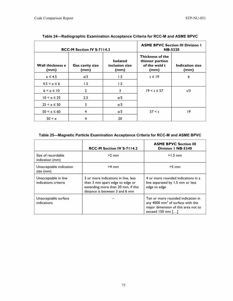
Code Comparison Report STP-NU-051
75
Table 24—Radiographic Examination Acceptance Criteria for RCC-M and ASME BPVC
RCC-M Section IV S-7114.3 ASME BPVC Section III Division 1
NB-5320
Wall thickness e (mm)
Gas cavity size (mm)
Isolated inclusion size
(mm)
Thickness of the thinner portion
of the weld t (mm)
Indication size (mm)
e ≤ 4.5 e/3 1.5 t ≤ 19 6
4.5 < e ≤ 6 1.5 1.5
6 < e ≤ 10 2 3 19 < t ≤ 57 t/3
10 < e ≤ 25 2.5 e/3
25 < e ≤ 50 3 e/3
50 < e ≤ 60 4 e/3 57 < t 19
50 < e 4 20
Table 25—Magnetic Particle Examination Acceptance Criteria for RCC-M and ASME BPVC
RCC-M Section IV S-7114.2 ASME BPVC Section III
Division 1 NB-5340
Size of recordable indication (mm)
>2 mm >1.5 mm
Unacceptable indication size (mm)
>4 mm >5 mm
Unacceptable in line indications criteria
3 or more indications in line, less than 3 mm apart edge to edge or extending more than 20 mm, if this distance is between 3 and 6 mm
4 or more rounded indications in a line separated by 1.5 mm or less edge to edge
Unacceptable surface indications
– Ten or more rounded indication in any 4000 mm2 of surface with the major dimension of this area not to exceed 150 mm […]
STP-NU-051 Code Comparison Report
76
4.8 Pressure Tests Highlights
• Higher hydrotest pressure in the RCC-M (B-5000) than in ASME NB-6200 • No pneumatic testing in the RCC-M.
This paragraph presents the pressure that should be chosen for the tests. These pressures can be found in RCC-M Section I B-5000, while it is Section III Division 1 NB-6220 that includes these provisions. Table 26 presents the layout in ASME BPVC and indicates where the equivalent paragraphs are located in the RCC-M Code. In this paragraph, only one table is proposed because no other section from the RCC-M covers pressure tests than the one specified in the Table 26, so unlike the other sections, there was no need to create a second table.
The ASME states that the hydrostatic test pressure should only be 1.25 times the design pressure.
The RCC-M gives another formula in the RCC-M Section I Z-Z720 to determine the factor to scale up the design pressure by a factor k, which is:
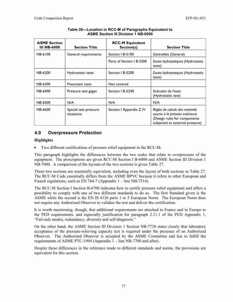
Code Comparison Report STP-NU-051
77
Table 26—Location in RCC-M of Paragraphs Equivalent to ASME Section III Division 1 NB-6000
ASME Section III NB-6000 Section Title
RCC-M Equivalent Section(s) Section Title
NB-6100 General requirements Section I B-5100 Généralités (General)
Parts of Section I B-5200 Essais hydrostatiques (Hydrostatic tests)
NB-6200 Hydrostatic tests Section I B-5200 Essais hydrostatiques (Hydrostatic tests)
NB-6300 Pneumatic tests Not covered
NB-6400 Pressure test gages Section I B-5240 Exécution de l’essai (Hydrostatic test)
NB-6500 N/A N/A N/A
NB-6600 Special test pressure situations
Section I Appendix Z IV Règles de calculs des matériels soumis à la pression extérieure (Design rules for components subjected to external pressure)
4.9 Overpressure Protection Highlights
• Two different certifications of pressure relief equipment in the RCC-M.
This paragraph highlights the differences between the two codes that relate to overpressure of the equipment. The prescriptions are given RCC-M Section I B-6000 and ASME Section III Division 1 NB-7000. A comparison of the layouts of the two sections is given Table 27.
These two sections are essentially equivalent, including even the layout of both sections in Table 27. The RCC-M Code essentially differs from the ASME BPVC because it refers to other European and French regulations, such as EN 764-7 (Appendix 1 – line NB-7314).
The RCC-M Section I Section B-6700 indicates how to certify pressure relief equipment and offers a possibility to comply with one of two different standards to do so. The first Standard given is the ASME while the second is the EN IS 4126 parts 1 to 5 European Norm. The European Norm does not require any Authorized Observer to validate the test and deliver the certification.
It is worth mentioning, though, that additional requirements are attached in France and in Europe to the PED requirements, and especially justification for paragraph 2.11.1 of the PED Appendix 1, “Fail-safe modes, redundancy, diversity and self-diagnosis.”
On the other hand, the ASME Section III Division 1 Section NB-7738 states clearly that laboratory acceptance of the pressure-relieving capacity test is required under the presence of an Authorized Observer. The Authorized Observer is accepted by the ASME Committee and has to fulfill the requirements of ASME PTC-1994 (Appendix 1 – line NB-7700 and after).
Despite these differences in the reference made to different standards and norms, the provisions are equivalent for this section.
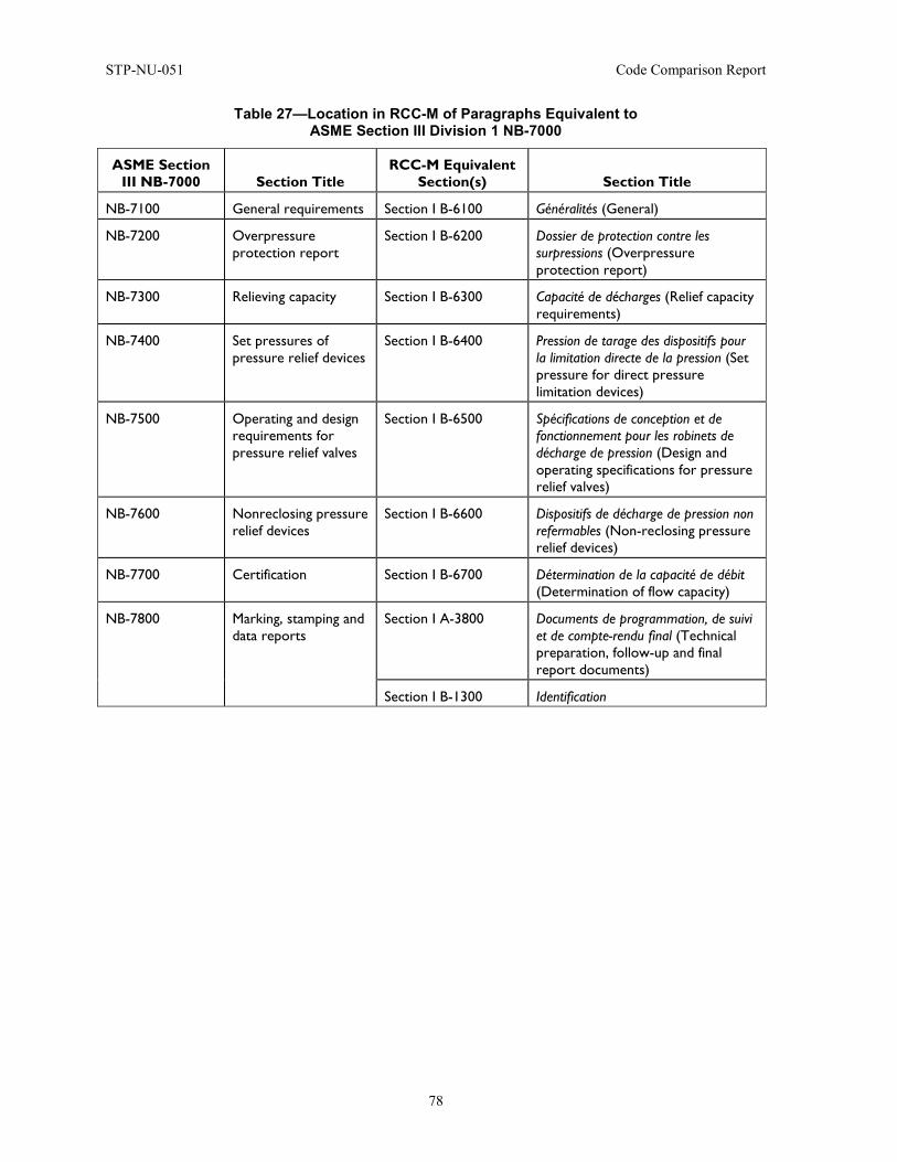
STP-NU-051 Code Comparison Report
78
Table 27—Location in RCC-M of Paragraphs Equivalent to ASME Section III Division 1 NB-7000
ASME Section III NB-7000 Section Title
RCC-M Equivalent Section(s) Section Title
NB-7100 General requirements Section I B-6100 Généralités (General)
NB-7200 Overpressure protection report
Section I B-6200 Dossier de protection contre les surpressions (Overpressure protection report)
NB-7300 Relieving capacity Section I B-6300 Capacité de décharges (Relief capacity requirements)
NB-7400 Set pressures of pressure relief devices
Section I B-6400 Pression de tarage des dispositifs pour la limitation directe de la pression (Set pressure for direct pressure limitation devices)
NB-7500 Operating and design requirements for pressure relief valves
Section I B-6500 Spécifications de conception et de fonctionnement pour les robinets de décharge de pression (Design and operating specifications for pressure relief valves)
NB-7600 Nonreclosing pressure relief devices
Section I B-6600 Dispositifs de décharge de pression non refermables (Non-reclosing pressure relief devices)
NB-7700 Certification Section I B-6700 Détermination de la capacité de débit (Determination of flow capacity)
NB-7800 Marking, stamping and data reports
Section I A-3800 Documents de programmation, de suivi et de compte-rendu final (Technical preparation, follow-up and final report documents)
Section I B-1300 Identification
Code Comparison Report STP-NU-051
79
4.10 Overview on Quality Aspects Highlights
• QA in the RCC-M Code is based on International standards and recommendations. • ASME uses NQA-1 versus RCC-M uses ISO-9001 and IAEA 50 C/SG. • Professional Engineer certification only exists in ASME Code.
While outside the scope of this report, a brief discussion is provided herein to identify some basic differences regarding Quality Assurance and Engineer Certification aspects of the codes.
On the request of the American National Standards Institute (ANSI), the ASME brought together the Committee on Nuclear Quality Assurance, which in 1979 issued the Nuclear Quality Assurance (NQA-1) report. This report provides quality assurance program requirements for Nuclear Type or N-Type Certificate Holders. The ASME refers to this Standard, in its Section III Division 1 NCA-4000.
The RCC-M refers in Section I A-5000 to a combination of the 50 C/SG Quality Standard written by the International Atomic Energy Agency (IAEA) and the ISO-9001/9002 Standard, first implemented in the late 1980s. The first objective of these ISO standards is customer satisfaction while the ASME Code relies on a very technical and nuclear industry oriented Standard.
Moreover, the ASME specifies, in its Section III Division 1 Section NCA-4000, the existence of an Authorized Inspection Agency (AIA) and Authorized Nuclear Inspectors (ANI). The ASME had assembled, in 1973, a Committee on Qualifications for Authorized Inspection (QAI), which issued the QAI-1 standard to qualify Authorities for Inspection. Even before that, the National Board of Boiler and Pressure Vessel Inspectors (NBBPVI) was created in 1919 to make sure that pressure vessels were built according to an acceptable standard and qualify inspectors capable of verifying the implementation of the standard. The NBBPVI nowadays qualifies the inspectors as per the QAI-1 to enable them to perform third-party verification of nuclear pressurized components.
The ASME developed Subsection NCA, which provides the general rules for ASME N-Type certification program for construction of Division 1 and 2 components, including Class 1 pressure vessels. The ASME N-Type certification program provides rules and requirements for designers, component owners, authorized inspection, professional engineers, material suppliers, qualification documents, and the application of the N-stamp, quality assurance, and registration with the ASME.
In contrast, the RCC-M gives more responsibility or freedom to the owners. Owners may here be the contractor, the manufacturer or the supplier, as specified in Section I A-5100. It is the responsibility of the owner to prepare and implement a quality system that is compliant with the code, to notify the various contractors, suppliers and manufacturers that it interfaces with of the quality system used and, finally, verify that they all are compliant with the defined quality system.
These are, in essence, two different ways of achieving the same objective.
There are also differences between the two codes as far as Personnel Qualification is concerned, especially in the area of Engineering Qualification. The ASME requires a Registered Professional Engineer to certify the component, the design specification, the overpressure protection report, design report and/or construction report.
For Engineering Qualification, the requirements of the ASME Code may be found in Section III Division 1, Appendix XXIII. It is described how to qualify a Professional Engineer, i.e., personnel able to certify Designs and Equipment. In practice, a Professional Engineer has to start the process after graduating with a Bachelor’s degree from an accredited university (accreditation by the Accreditation Board of Engineering and Technology [ABET]) by taking the Fundamentals in Engineering (FE) exam.
STP-NU-051 Code Comparison Report
80
After gaining experience in one specialty field as well as in regulation and licensure requirements (4 years), the final step is then to take the final Professional Engineering exam.
In the RCC-M, there is no such equivalent accreditation. The code does not address this certification, but every company has a QA program and internal requirements to assign engineers to particular tasks. The tools that can be used to assess the technical ability of an individual or an engineering organization are numerous. They range from simply looking at the résumés to looking at the scientific publications of an individual. It should also be noted that the IAEA 50 SG/Q, ISO 9001 and also, when applied, the non-mandatory Appendices ZZ and ZY, all require adequate competence of personnel. As for the manufacturer certification above, it is the owner responsibility to ensure this last point.
To conclude, it should not be forgotten that the RCC-M is a set of guidelines that is almost compulsory to follow in practice, but the French ASN does not enforce the use of any code. The AFCEN is, nevertheless, in close contact with the ASN to periodically collect its comments about the code. Moreover, an external document measuring the adequacy of the RCC-M provisions to the directives can be found (RM 09012, “File regarding the assessment of RCC-M Ed.2007 requirements versus ESPN Order of December, 12th 2005”). Nevertheless, on the European and French markets, the European directives and French laws are above the code and should be the first point of entry when manufacturing equipment for these markets.
For a strict consideration of QA, it must be noted that countries such as France, Finland and the United Kingdom have specific regulations that supersede any Code requirements.
4.11 Conclusion A preliminary remark is that this conclusion does not include the results of Section 4.10, “Overview On Quality Aspects,” as this paragraph is clearly out of the scope of the report as defined in the Introduction.
Two charts summarizing the differences based on the Appendix 1 can be seen Figure 23 and Figure 24. These two bar diagrams give a good general picture of the nature and number of differences between the two codes.
To summarize what has been said before, the first point concerns the prescriptive nature of the RCC-M Code compared to the ASME. The RCC-M dictates the specific design of a respective component to a greater degree than ASME Section III, which, due to the broader scope, leaves more responsibility to the owner (designer and/or manufacturer). As defined in the foreword, the ASME BPVC is intended to apply broadly to the mechanical equipment industry, while the RCC-M focuses on PWR components and is derived from the industrial experience in France. The ASME BPVC is intended to apply more generally and does not attempt to represent the specific experience of a single industry, as is the case regarding the RCC-M Code. In practice, the owners (individual utilities, designers and/or manufacturers) define the additional experience-based requirements used in conjunction with the requirements defined in the ASME BPVC to achieve an end result.
The second point concerns the evolutionary nature of the RCC-M, which tends to include more experience feedback, as can be illustrated by the part of the code on cleanliness, stemming directly from practical cases. Since its first edition in 1984, materials have been added, paragraphs have evolved and new results from R&D have been integrated.
These are two different approaches. The RCC-M approach, being more prescriptive, will guide the user to attain the desired end result, whereas, although a similar end will likely result through implementation of the ASME Section III rules by an experienced designer, the ASME does not provide the same level of direction. This difference is particularly apparent with respect to selection of materials. While, except for a few instances particularly based on French experience, the materials
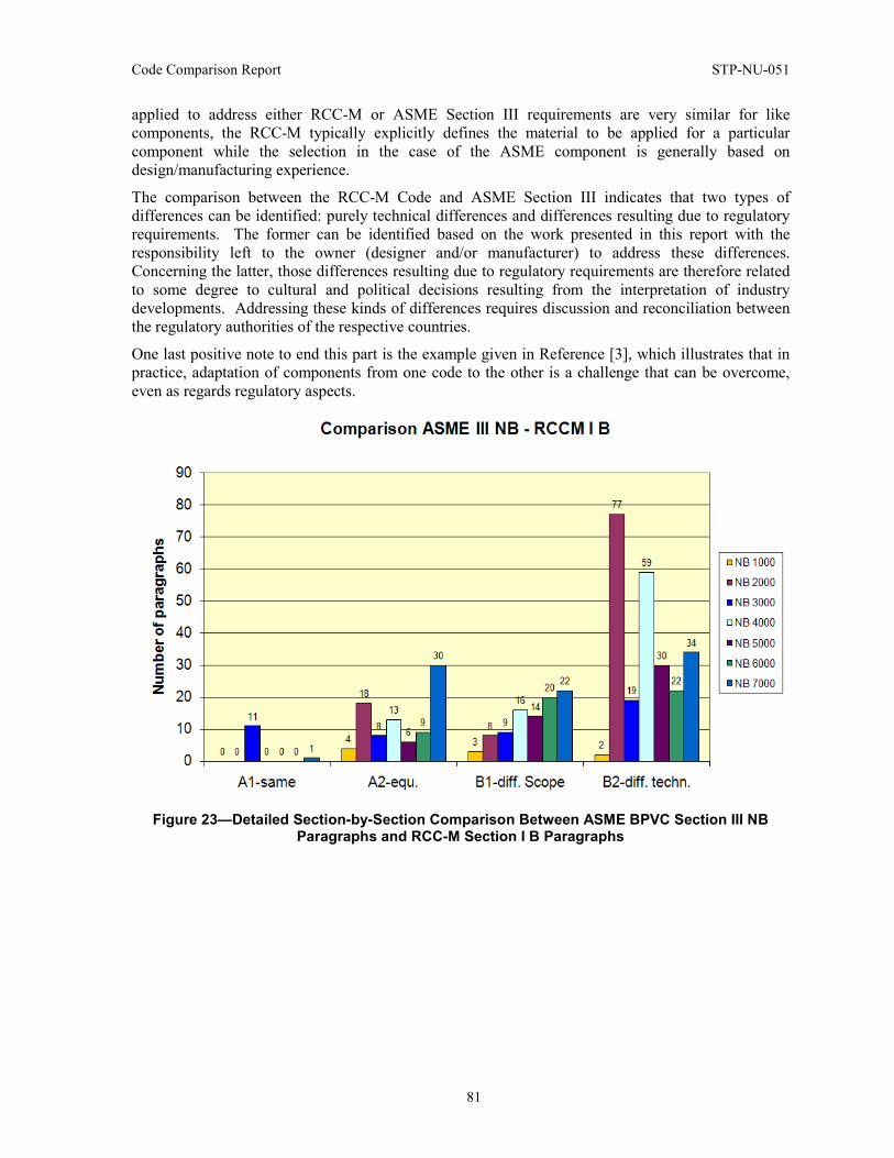
Code Comparison Report STP-NU-051
81
applied to address either RCC-M or ASME Section III requirements are very similar for like components, the RCC-M typically explicitly defines the material to be applied for a particular component while the selection in the case of the ASME component is generally based on design/manufacturing experience.
The comparison between the RCC-M Code and ASME Section III indicates that two types of differences can be identified: purely technical differences and differences resulting due to regulatory requirements. The former can be identified based on the work presented in this report with the responsibility left to the owner (designer and/or manufacturer) to address these differences. Concerning the latter, those differences resulting due to regulatory requirements are therefore related to some degree to cultural and political decisions resulting from the interpretation of industry developments. Addressing these kinds of differences requires discussion and reconciliation between the regulatory authorities of the respective countries.
One last positive note to end this part is the example given in Reference [3], which illustrates that in practice, adaptation of components from one code to the other is a challenge that can be overcome, even as regards regulatory aspects.
Figure 23—Detailed Section-by-Section Comparison Between ASME BPVC Section III NB Paragraphs and RCC-M Section I B Paragraphs
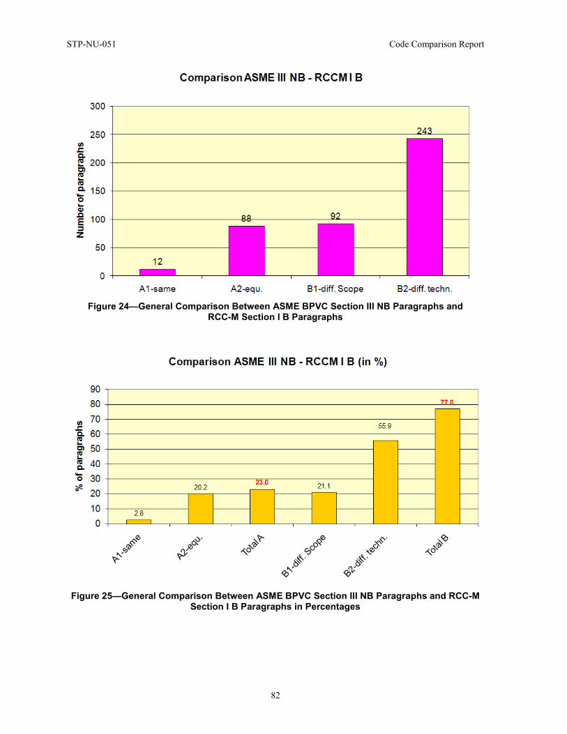
STP-NU-051 Code Comparison Report
82
Figure 24—General Comparison Between ASME BPVC Section III NB Paragraphs and
RCC-M Section I B Paragraphs
Figure 25—General Comparison Between ASME BPVC Section III NB Paragraphs and RCC-M
Section I B Paragraphs in Percentages
Code Comparison Report STP-NU-051
83
5 JSME VERSUS ASME BPVC SECTION III COMPARISON
5.1 Abstract The JSME nuclear code (JSME S-NC-1 2008: Rules on Design and Construction for NPPs, Division 1, LWRs) is currently primarily applied to domestic plants in Japan.
Considering globalization of the nuclear industry, it is considered beneficial for the industry in general that the similarities and differences of the codes and standards of various countries be identified and clarified to support possible future harmonization of these codes and standards. From this perspective, a comprehensive line-by-line comparison was made between JSME S-NC-1 and ASME BPVC Section III for Class 1 component rules. This part of the report describes the main result of the comparison.
As a result of the comparison, it was found that the very basic technical requirements are the same between ASME BPVC Section III and JSME S-NC-1. In particular, the basic design allowable limits for the failure modes that should be considered in design and operating conditions are fundamentally identical. This similarity comes from the fact that the origin of the JSME Code is based on repealed government regulation, METI Notification 501, which essentially relied on ASME BPVC Section III.
There are, of course, a number of minor differences in the requirements of JSME and ASME Codes. A large part of these differences fall into a category of ASME requirements that are not addressed or addressed in less detail in JSME.
It should be also noted that the Quality Assurance (QA) related and administrative requirements are quite different between JSME and ASME, reflecting the difference of regulatory environment and industry practice between Japan and the U.S.
5.2 Introduction The comparison of JSME and ASME Codes on the rules of Class 1 components (vessels, piping, pumps and valves) is described in this section. First, a description of the comparison scope and strategy is provided, and then the comparison results are given, where the major differences are summarized. Appendix 2 provides summary tables that identify the major differences between JSME and ASME Code rules on the Class 1 vessel and Class 1 components (piping, pumps and valves), respectively.
As was agreed upon among the participating SDOs, the first comparison was made on the rules for Class 1 components (vessels, piping, pumps and valves), and JSME made comparison between JSME and ASME Codes. Along with the comparison of the technical requirements, the QA and related administrative requirements were also included in the comparison.
A detailed, line-by-line comparison was made of the JSME Code technical requirements with corresponding ASME requirements, and the comparison results were summarized in a tabular format. Sources or causes of the major differences were identified and classified, which will be discussed in the latter portion of this report.
As for the QA requirements, contrary to the technical requirements, comparison was made on the whole, since the code organization and contents of the QA requirements are significantly different between Japan and the U.S.
STP-NU-051 Code Comparison Report
84
For the technical part of the design and construction rules for Class 1 vessels, the following ASME and JSME Codes were subjected to comparison.
(a) For ASME,
(1) ASME B&PV Code Section III 2007 Edition, Subsection NB, Class 1 Components: Articles NB-1000 through NB-7000
(2) Related Appendices
(b) For JSME Nuclear Power Generation Facility Codes,
(1) JSME Nuclear Power Generation Facility Codes
(2) JSME S-NC1-2008: Rules on Design and Construction for NPPs, Div. 1 LWRs
(3) JSME S-NB1-2007: Rules on Welding for NPPs
(4) JSME S-NJ1-2008: Rules on Materials for Nuclear Facilities.
For the general and QA related requirements, the following ASME and JSME Codes were subjected to comparison.
(a) For ASME,
(1) ASME B&PV Code Section III 2007 Edition, Subsection NCA
(2) ASME NQA-1-1994
(b) For JSME and JEA2,
(1) JSME S-NC1-2008: Rules on Design and Construction for NPPs, Div. 1 LWRs
(2) JEAC 4111-2003: Code of Quality Assurance for Nuclear Power Plant Safety3.
The comparison results were classified into the following four categories.
1. Equivalent Code requirements of ASME and JSME are practically the same.
2. Not Equivalent Requirements in JSME are different from those in ASME.
3. Not Addressed in JSME No rules in JSME corresponding to ASME requirement.
4. JSME Unique Rules unique to JSME and not addressed in ASME.
2JEA: Japan Electric Association, one of three major SDOs for nuclear codes and standards of Japan. 3Unofficial translation of the code title.
Code Comparison Report STP-NU-051
85
5.3 Preliminary Paragraphs and Scope Presentation Highlights
• No stamping and no certificate holder in JSME S-NC1 • No detailed boundaries of jurisdiction consideration in JSME S-NC1.
This section summarizes the major differences between the introductory paragraphs of ASME BPVC Section III Division 1 NB 1000 and JSME S-NC1 section GNR.
One of the most significant differences is that marking, stamping and preparation of reports by the Certificate Holder of items are not required in JSME. The scope of JSME S-NC1 is limited to material, design, fabrication, examination, testing and overpressure relief. This difference is closely related to the significant differences of QA/QC requirements between ASME and JSME, which is overviewed in Section 5.11 of this report. Behind these differences lies the historical background of JSME S-NC1 development. JSME S-NC1 was first developed, by policy, mainly based on MITI Notification No. 501, which contained the detailed technical rules for structural design of nuclear components established by the regulatory authority. In developing MITI Notification No. 501, they sifted through ASME Section III and adopted provisions therein that were judged necessary from the regulator’s point of view. With this background, there are number of provisions that exist in ASME Section III but not in JSME Code.
Differences are also found in the boundary of jurisdiction. The boundaries of components and jurisdiction are described clearly and in detail in ASME NB-1130, while JSME S-NC1 has limited descriptions. First, while ASME NB-1131 mandates the Design Specification to define the boundary of a component to which piping or another component is attached, JSME S-NC1 does not. In JSME S-NC1, descriptions are only given that correspond to NB-1132.2 (a) through (e). In JSME, there are no explicit distinctions between pressure-retaining and non-pressure-retaining attachments, or structural or nonstructural attachments (NB-1132.1) either.
The last major difference in this section is component classification definitions. While, in ASME, the component classification is entrusted to the Design Specification, component classification definitions are given in JSME S-NC1, such as, “Class 1 components are those components that constitute the reactor coolant pressure boundary.” Lists of major systems and components that belong to each class (Classes 1, 2, 3, MC, etc.) are given in the explanatory part of JSME S-NC1 (which is not the code itself). This comes also from the historical background of JSME S-NC1.
5.4 Materials Highlights
• JSME does not specify welding materials.
Generally, the requirements for test coupons, fracture toughness test, nondestructive examinations (NDE) for base material and repair activities (NB-2000 in ASME) are almost the same between JSME and ASME. However, there are some differences between JSME and ASME that are listed below.
First, JSME does not define nomenclatures in detail as ASME NB-2110, e.g., JSME does not define “pressure-retaining material” or “nominal thickness.”
Second, JSME does not specify welding materials, NB-2121. Manufacture qualifies applicable welding material based on the welding procedure qualification test conducted in accordance with the performance requirement of Part 2 of JSME S NB1-2007, “Rules on Welding for Nuclear Power
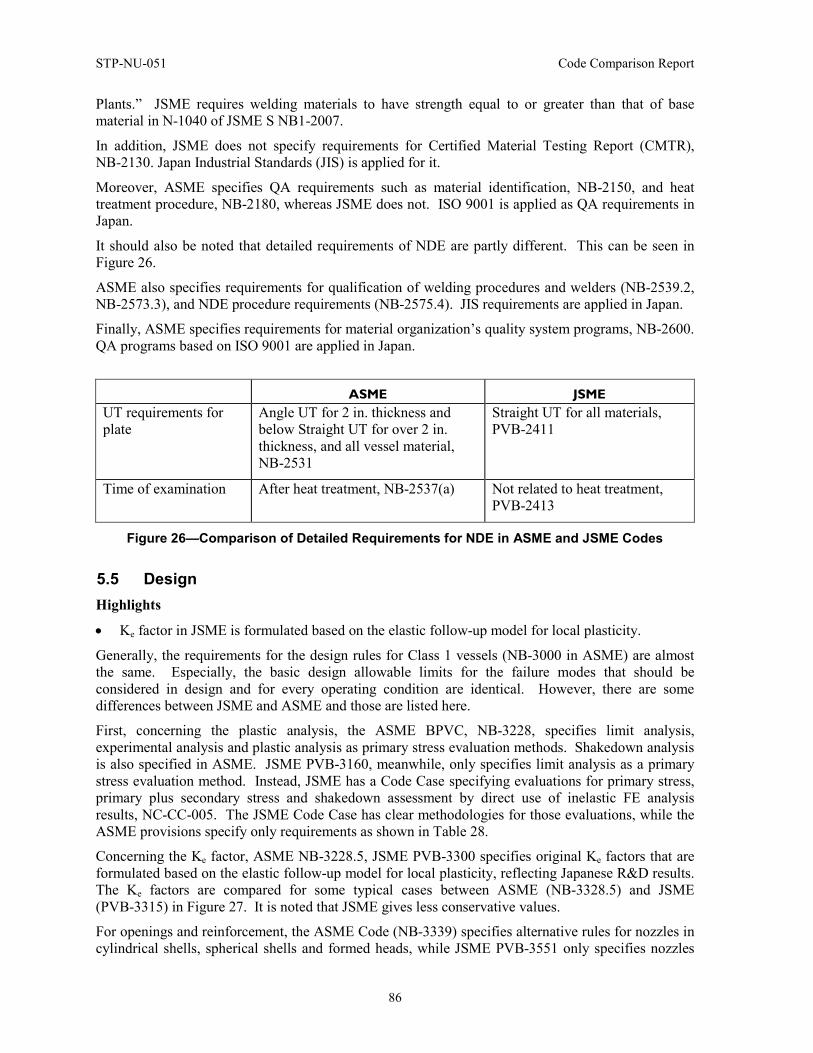
STP-NU-051 Code Comparison Report
86
Plants.” JSME requires welding materials to have strength equal to or greater than that of base material in N-1040 of JSME S NB1-2007.
In addition, JSME does not specify requirements for Certified Material Testing Report (CMTR), NB-2130. Japan Industrial Standards (JIS) is applied for it.
Moreover, ASME specifies QA requirements such as material identification, NB-2150, and heat treatment procedure, NB-2180, whereas JSME does not. ISO 9001 is applied as QA requirements in Japan.
It should also be noted that detailed requirements of NDE are partly different. This can be seen in Figure 26.
ASME also specifies requirements for qualification of welding procedures and welders (NB-2539.2, NB-2573.3), and NDE procedure requirements (NB-2575.4). JIS requirements are applied in Japan.
Finally, ASME specifies requirements for material organization’s quality system programs, NB-2600. QA programs based on ISO 9001 are applied in Japan.
ASME JSME UT requirements for plate
Angle UT for 2 in. thickness and below Straight UT for over 2 in. thickness, and all vessel material, NB-2531
Straight UT for all materials, PVB-2411
Time of examination After heat treatment, NB-2537(a) Not related to heat treatment, PVB-2413
Figure 26—Comparison of Detailed Requirements for NDE in ASME and JSME Codes
5.5 Design Highlights
• Ke factor in JSME is formulated based on the elastic follow-up model for local plasticity.
Generally, the requirements for the design rules for Class 1 vessels (NB-3000 in ASME) are almost the same. Especially, the basic design allowable limits for the failure modes that should be considered in design and for every operating condition are identical. However, there are some differences between JSME and ASME and those are listed here.
First, concerning the plastic analysis, the ASME BPVC, NB-3228, specifies limit analysis, experimental analysis and plastic analysis as primary stress evaluation methods. Shakedown analysis is also specified in ASME. JSME PVB-3160, meanwhile, only specifies limit analysis as a primary stress evaluation method. Instead, JSME has a Code Case specifying evaluations for primary stress, primary plus secondary stress and shakedown assessment by direct use of inelastic FE analysis results, NC-CC-005. The JSME Code Case has clear methodologies for those evaluations, while the ASME provisions specify only requirements as shown in Table 28.
Concerning the Ke factor, ASME NB-3228.5, JSME PVB-3300 specifies original Ke factors that are formulated based on the elastic follow-up model for local plasticity, reflecting Japanese R&D results. The Ke factors are compared for some typical cases between ASME (NB-3328.5) and JSME (PVB-3315) in Figure 27. It is noted that JSME gives less conservative values.
For openings and reinforcement, the ASME Code (NB-3339) specifies alternative rules for nozzles in cylindrical shells, spherical shells and formed heads, while JSME PVB-3551 only specifies nozzles
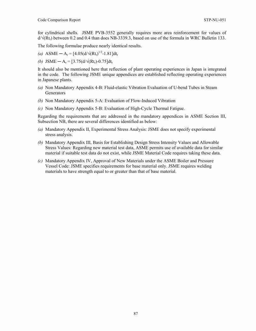
Code Comparison Report STP-NU-051
87
for cylindrical shells. JSME PVB-3552 generally requires more area reinforcement for values of d/√(Rtr) between 0.2 and 0.4 than does NB-3339.3, based on use of the formula in WRC Bulletin 133.
The following formulae produce nearly identical results.
(a) ASME ─ Ar = [4.05(d/√(Rtr)1/2-1.81]dtr
(b) JSME ─ Ar = [3.75(d/√(Rtr)-0.75]dtr
It should also be mentioned here that reflection of plant operating experiences in Japan is integrated in the code. The following JSME unique appendices are established reflecting operating experiences in Japanese plants.
(a) Non Mandatory Appendix 4-B: Fluid-elastic Vibration Evaluation of U-bend Tubes in Steam Generators
(b) Non Mandatory Appendix 5-A: Evaluation of Flow-Induced Vibration
(c) Non Mandatory Appendix 5-B: Evaluation of High-Cycle Thermal Fatigue.
Regarding the requirements that are addressed in the mandatory appendices in ASME Section III, Subsection NB, there are several differences identified as below:
(a) Mandatory Appendix II, Experimental Stress Analysis: JSME does not specify experimental stress analysis.
(b) Mandatory Appendix III, Basis for Establishing Design Stress Intensity Values and Allowable Stress Values: Regarding new material test data, ASME permits use of available data for similar material if suitable test data do not exist, while JSME Material Code requires taking these data.
(c) Mandatory Appendix IV, Approval of New Materials under the ASME Boiler and Pressure Vessel Code: JSME specifies requirements for base material only. JSME requires welding materials to have strength equal to or greater than that of base material.
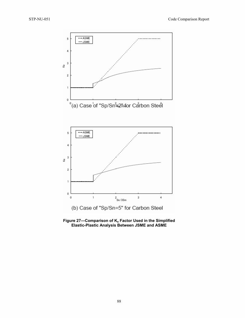
STP-NU-051 Code Comparison Report
88
Figure 27—Comparison of Ke Factor Used in the Simplified Elastic-Plastic Analysis Between JSME and ASME
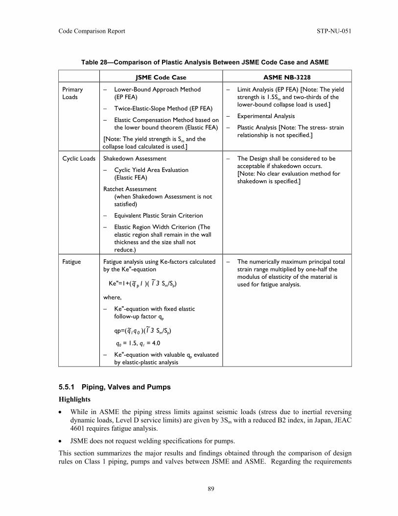
Code Comparison Report STP-NU-051
89
Table 28—Comparison of Plastic Analysis Between JSME Code Case and ASME
JSME Code Case ASME NB-3228
Primary Loads
– Lower-Bound Approach Method (EP FEA)
– Twice-Elastic-Slope Method (EP FEA)
– Elastic Compensation Method based on the lower bound theorem (Elastic FEA)
[Note: The yield strength is Sm and the collapse load calculated is used.]
– Limit Analysis (EP FEA) [Note: The yield strength is 1.5Sm and two-thirds of the lower-bound collapse load is used.]
– Experimental Analysis
– Plastic Analysis [Note: The stress- strain relationship is not specified.]
Cyclic Loads Shakedown Assessment
– Cyclic Yield Area Evaluation (Elastic FEA)
Ratchet Assessment (when Shakedown Assessment is not satisfied)
– Equivalent Plastic Strain Criterion
– Elastic Region Width Criterion (The elastic region shall remain in the wall thickness and the size shall not reduce.)
– The Design shall be considered to be acceptable if shakedown occurs. [Note: No clear evaluation method for shakedown is specified.]
Fatigue Fatigue analysis using Ke-factors calculated by the Ke"-equation
Ke"=1+( 1q~p )( 31~ Sm/Sp)
where,
– Ke"-equation with fixed elastic follow-up factor qp
qp=( 01qq~ )( 31~ Sm/Sp)
q0 = 1.5, q1 = 4.0
– Ke"-equation with valuable qp evaluated by elastic-plastic analysis
– The numerically maximum principal total strain range multiplied by one-half the modulus of elasticity of the material is used for fatigue analysis.
5.5.1 Piping, Valves and Pumps Highlights
• While in ASME the piping stress limits against seismic loads (stress due to inertial reversing dynamic loads, Level D service limits) are given by 3Sm with a reduced B2 index, in Japan, JEAC 4601 requires fatigue analysis.
• JSME does not request welding specifications for pumps.
This section summarizes the major results and findings obtained through the comparison of design rules on Class 1 piping, pumps and valves between JSME and ASME. Regarding the requirements
STP-NU-051 Code Comparison Report
90
other than design, i.e., material, fabrication, examination and testing, the similarities and differences between JSME and ASME are actually the same as in the case of Class 1 vessels; the comparison was rather focused on the design requirements.
The portions JSME and ASME Codes subjected to comparison are summarized in Table 29.
A summary table of the major differences is given in the Appendix 2. This section is divided into three parts: the first one concerning the piping design, the second, the pump design, and the third and final, the valve design.
First, concerning the piping design, the first paragraph addresses considerations for Local Conditions and Transients (NB-3612.4). These ASME requirements on piping systems design aspects are not addressed in JSME. They are covered by the requirements of the applicable ministerial ordinance or manufacturer’s practice.
When it comes to allowance (Corrosion or Erosion, NB-3613.1), ASME requires that when corrosion or erosion is expected, the allowance of wall thickness shall be considered. On the contrary, JSME does not require consideration of corrosion or erosion in the design phase, while in the actual design practices they are considered by the industry designers. In addition, for the operation and maintenance phase, requirements are specified by another standard for the management and control of piping wall thickness by periodical measurement for identified piping portions of potential erosion or corrosion (JSME S CA1-2005, “Rules on Pipe Wall Thinning Management”).
For threading, grooving, miters and extruded outlet piping (NB-3613.2, NB-3643.2, NB-3644), ASME allows the usage of threading, grooving, miters and extruded outlet piping, while JSME stipulates that connections between pipes shall be limited to a welding joint or a flange joint (PPB-3430).
Furthermore, the requirement for miters and extruded outlet piping does not exist in JSME since these items are not used in the actual plants.
Concerning Design and Service Loadings (NB-3621), ASME identifies and classifies the loads to be concerned in design with detail and clear definitions, while JSME leaves them to the design specification (GNR-2220 and PPA-3300).
About the requirements for Class 1 Piping Analysis (NB-3630), ASME states that piping of NPS1 or less may be designed in accordance with the design requirements of NC (Class 2 piping), while JSME does not have such an alternative route. Class1 piping shall be designed in accordance with the design requirements of PPB (Class1 Piping).
For the elbow requirements (NB-3642.2), ASME states that the wall thickness of a short elbow crotch region (the portion of Φ=210~330° defined in Figure 28) shall be 20% greater than the minimum wall thickness required for the straight pipe, but JSME does not have such a requirement.
Another difference relates to the requirement for reinforcement (NB-3643.3). Although two-thirds of the opening reinforcement must be required within the defined region, a part of an equation to calculate the defined region is not stipulated in JSME (PPB-3424).
Although the definite distance between two openings shall be required for two unreinforced openings in order not to have reinforcements, a part of the requirement for openings not requiring reinforcement is not stipulated in ASME (PPB-3422).
In the case of two openings closer to each other, JSME defines the available ranges for reinforcement and the distance between two openings, while these definitions are not stipulated in ASME (NB-3643.3 versus PPB-3424).
Code Comparison Report STP-NU-051
91
Rules for the nozzle type of branch connection in JSME differ from ASME. Although the latter approves partial-penetration welding on branch connections, JSME does not approve it and applies full penetration only.
The next difference is the requirement for closure (NB-3646). ASME states the pressure requirements on closures. JSME requires separate pressure requirements for both paneling and plate, and these requirements are based on the ones for Class 2 components (PPB-3413, PPB-3415.2).
JSME requires the applicable condition of opening on head (panel) (PPB-3423), but ASME does not require it and has the definition for the required thickness of a head depend on the opening location on the head.
Concerning the requirement for permanent blanks (NB-3647.2), ASME approves permanent blanks, while JSME does not approve and they are not used for actual plants.
In addition, ASME approves temporary blanks (NB-3647.3), while JSME does not take it as the item needs to comply with the Codes.
Currently, expansion joints (NB-3649.1) cannot be applied under ASME and JSME. ASME has been working on developing the applicable rule.
There are some differences in the allowable stresses between JSME and ASME that include allowable primary stresses for Level A and B Service limits, allowable stresses for dynamic (seismic) loads. The allowable stresses are compared in Table 30.
ASME defines the allowable primary stress (Min (1.8Sm, 1.5Sy), NB-3653, etc.) for Level B Service Limits. On the contrary, JSME does not define allowable primary stresses for Level A and B Service Limits.
ASME defines allowable stress for the loads including reversing dynamic loads (NB-3656, etc.) that is different from those for (B2' =2/3 B2), where a seismic load is considered to be a typical reversing dynamic load. While JSME does not define allowable stresses for seismic condition, JEAC 4601, which is the seismic design code in Japan, requires fatigue damage evaluation instead of primary stress limit.
Furthermore, JSME PPB-3536 (Simplified Elastic-Plastic Analysis) requires that new Ke Factor (NB-3653.6, etc.) shall be applied to obtain alternating stress intensities (refer to PVB-3315). The Ke Factor is obtained by Japanese R&D results.
In addition, ASME defines the matters that shall be accounted in piping design. Examples are as follows.
(a) Design Limits of Flanged Joints (NB-3658): ASME defines the allowable moments for flanged joints in Level A to D Service Limits. However, JSME defines that flanges shall be designed to use the equivalent pressure that is converted from moments on flanges.
(b) Definitions of Joint Design (NB-3671): ASME defines the requirements for treaded joint, flared joints, compression joints and caulked joints, et al., as connections without welding. However, JSME requires that Class 1 piping shall be used welded joints or flanged joints, so JSME does not define the requirement of a wide variety of joints.
(c) Flexibility of Piping (NB-3672) Design Limits of Flanged Joints (NB-3658): ASME defines the general requirements of flexibilities (NB-3672) that piping shall be designed to have sufficient flexibility and cold springing that the maximum allowable stress due to cold springing is 2.0Sm (NB-3672.8, etc.). In Japan, flexibility is considered as part of general requirements and these requirements are not described in JSME.
STP-NU-051 Code Comparison Report
92
Now turning to the pump design, one of the first differences relates to the scope and applicability (NB-3411). Among the portions and parts defined in ASME, there are some that are not included in JSME, e.g., seal housing and seal glands, and so on. This difference goes back to MITI Notification 501, on which the JSME Code is based.
MITI Notification No. 501 defined a pressure-retaining boundary from the viewpoint that it is important that the pressure-retaining parts not be damaged and pumped fluid not leak outside. Leakage is restricted by the labyrinth, and the bearing, etc. of the pump, even if parts such as mechanical seals were damaged (NB-3411). MITI Notification No. 501 did not define these parts as subject to regulation.
Another difference relates to the requirement against corrosion (NB-3418). Because quantification is difficult, it is not regulated in JSME, though consideration to environmental effects such as corrosion is requested in ASME.
Concerning the requirements for welding (NB-3431), JSME does not request welding specification.
It is the same for reinforcement of openings (NB-3433): JSME does not specify reinforcement of openings. However, when openings are necessary except inlet or outlet, it is acceptable to analyze stress taking into account openings and stress does not exceed the allowable value defined in the regulation.
Piping and supports (NB-3435, NB-3438) are specified in other articles of JSME Code, and are not included in articles of the pump.
Finally, this last part covers valve design. A first notable difference relates to the evaluation of secondary stresses on valve casing by pipe reaction forces (NB-3545.2 (b)). JSME (VVB-3330) evaluates all tensile, bending and torsion forces of pipes as pipe reaction forces on a valve casing, but ASME evaluates only bending forces of pipes.
JSME recognizes only a flange structure as a joint structure of body and bonnet (NB-3546.1) but does not recognize a general pressure-sealing structure for high-pressure valves. Contrarily, ASME recognizes particular joint structures including the pressure-sealing structure.
As for the valve fatigue evaluation (NB-3550), JSME (VVB-3370) does not admit the exceptive stipulation (excluding fatigue evaluation due to temperature change) that is admitted by ASME. In the exceptive stipulation, JSME performs a fatigue evaluation in a narrower temperature difference range (lower than 14°C) for stainless steel, while ASME adopts a temperature difference range of lower than 17°C (30°F) for both carbon and stainless steel.
Furthermore, ASME evaluates quakeproof (NB-3524) values given in a design specification by a static loading test. However, JSME includes no relevant description but JEAG 4601(1984)/ JEAC 4601(2008) includes the relevant description.
JEAG stipulates the soundness of a valve body even if a pipe connected to the valve breaks down, together with a quakeproof performance evaluation by “confirmed acceleration levels” that were obtained by a series of active function tests (vibration tests) and static loading tests.
Finally, ASME stipulates materials and structures of safety valves (NB-3590), while JSME does not. JSME (SRV-3010) stipulates that materials and structures of safety valves should conform to JIS B8210.
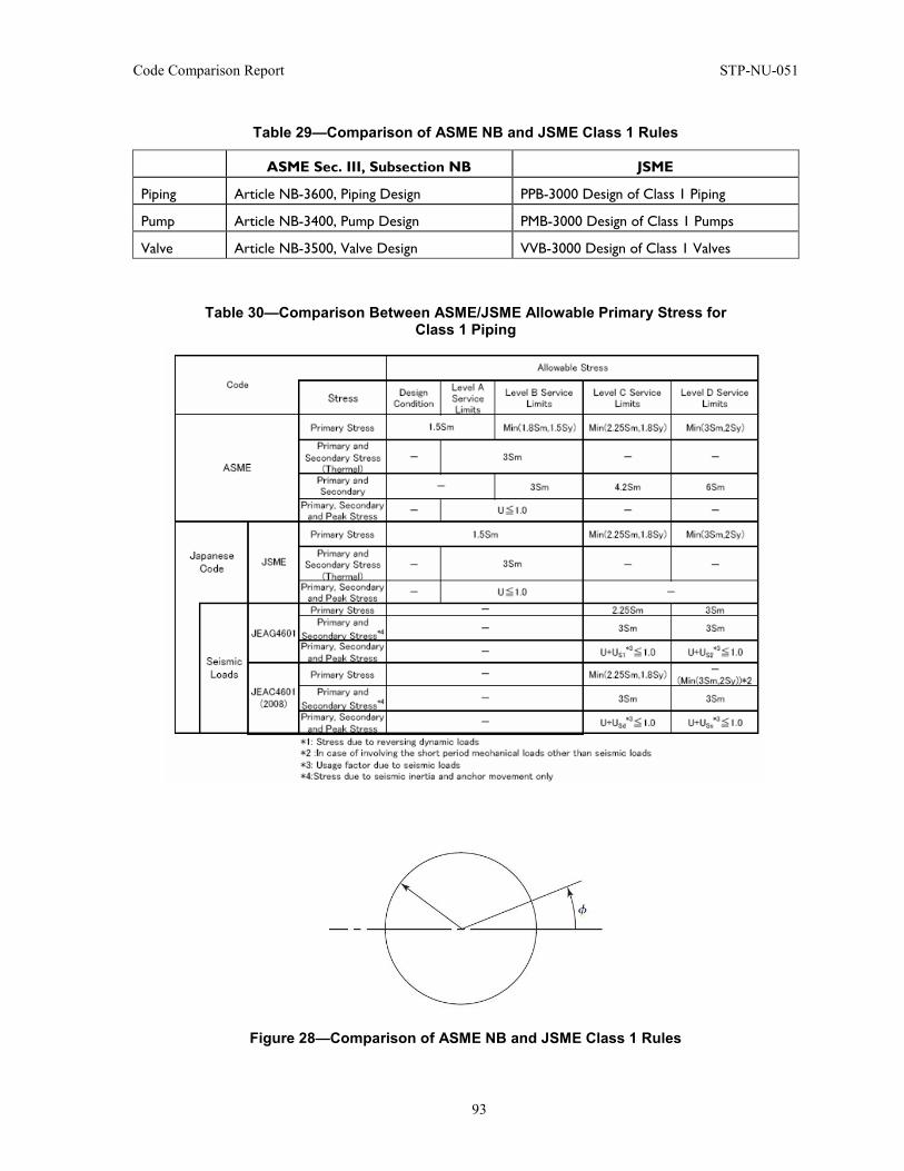
Code Comparison Report STP-NU-051
93
Table 29—Comparison of ASME NB and JSME Class 1 Rules
ASME Sec. III, Subsection NB JSME
Piping Article NB-3600, Piping Design PPB-3000 Design of Class 1 Piping
Pump Article NB-3400, Pump Design PMB-3000 Design of Class 1 Pumps
Valve Article NB-3500, Valve Design VVB-3000 Design of Class 1 Valves
Table 30—Comparison Between ASME/JSME Allowable Primary Stress for Class 1 Piping
Figure 28—Comparison of ASME NB and JSME Class 1 Rules
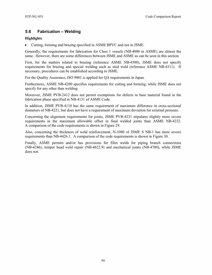
STP-NU-051 Code Comparison Report
94
5.6 Fabrication – Welding Highlights
• Cutting, forming and brazing specified in ASME BPVC and not in JSME.
Generally, the requirements for fabrication for Class 1 vessels (NB-4000 in ASME) are almost the same. However, there are some differences between JSME and ASME as can be seen in this section.
First, for the matters related to brazing (reference ASME NB-4500), JSME does not specify requirements for brazing and special welding such as stud weld (reference ASME NB-4311). If necessary, procedures can be established according to JSME.
For the Quality Assurance, ISO 9001 is applied for QA requirements in Japan.
Furthermore, ASME NB-4200 specifies requirements for cutting and forming, while JSME does not specify for any other than welding.
Moreover, JSME PVB-2412 does not permit exemptions for defects in base material found in the fabrication phase specified in NB-4131 of ASME Code.
In addition, JSME PVB-4110 has the same requirement of maximum difference in cross-sectional diameters of NB-4221, but does not have a requirement of maximum deviation for external pressure.
Concerning the alignment requirements for joints, JSME PVB-4231 stipulates slightly more severe requirements in the maximum allowable offset in final welded joints than ASME NB-4232. A comparison of the code requirements is shown in Figure 29.
Also, concerning the thickness of weld reinforcement, N-1080 of JSME S NB-1 has more severe requirements than NB-4426.1. A comparison of the code requirements is shown in Figure 30.
Finally, ASME permits and/or has provisions for fillet welds for piping branch connections (NB-4246), temper bead weld repair (NB-4622.9) and mechanical joints (NB-4700), while JSME does not.
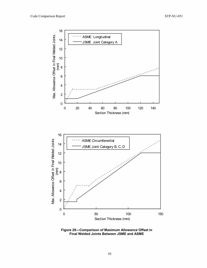
Code Comparison Report STP-NU-051
95
Figure 29—Comparison of Maximum Allowance Offset in Final Welded Joints Between JSME and ASME
0
2
4
6
8
10
12
14
16
0 20 40 60 80 100 120 140Section Thickness (mm)
Max
. Allo
wanc
e O
ffset
in F
inal
Wel
ded
Join
ts(m
m)
ASME LongitudinalJSME Joint Category A
0
2
4
6
8
10
12
14
16
0 50 100 150Section Thickness (mm)
Max
. Allo
wanc
e O
ffset
in F
inal
Wel
ded
Join
ts(m
m)
ASME CircumferentialJSME Joint Category B, C, D
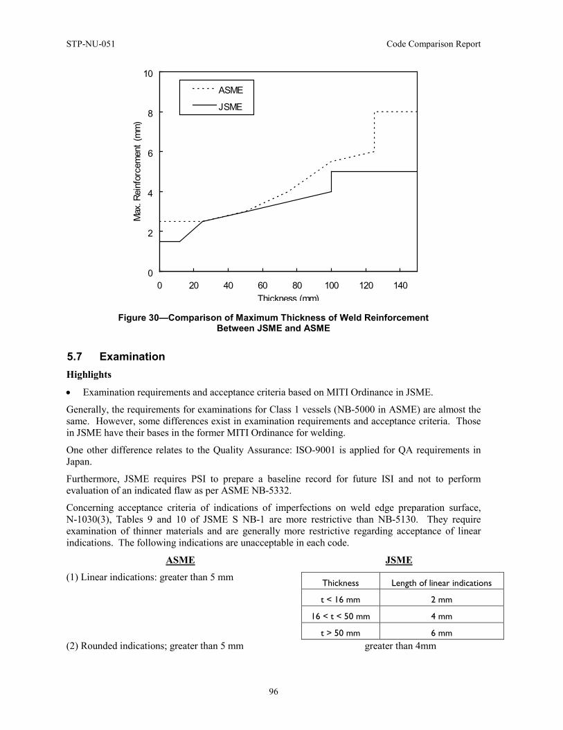
STP-NU-051 Code Comparison Report
96
Figure 30—Comparison of Maximum Thickness of Weld Reinforcement Between JSME and ASME
5.7 Examination Highlights
• Examination requirements and acceptance criteria based on MITI Ordinance in JSME.
Generally, the requirements for examinations for Class 1 vessels (NB-5000 in ASME) are almost the same. However, some differences exist in examination requirements and acceptance criteria. Those in JSME have their bases in the former MITI Ordinance for welding.
One other difference relates to the Quality Assurance: ISO-9001 is applied for QA requirements in Japan.
Furthermore, JSME requires PSI to prepare a baseline record for future ISI and not to perform evaluation of an indicated flaw as per ASME NB-5332.
Concerning acceptance criteria of indications of imperfections on weld edge preparation surface, N-1030(3), Tables 9 and 10 of JSME S NB-1 are more restrictive than NB-5130. They require examination of thinner materials and are generally more restrictive regarding acceptance of linear indications. The following indications are unacceptable in each code.
ASME JSME
(1) Linear indications: greater than 5 mm
(2) Rounded indications; greater than 5 mm greater than 4mm
0
2
4
6
8
10
0 20 40 60 80 100 120 140Thickness (mm)
Max
. Rei
nfor
cem
ent (
mm
)
ASME
JSME
Thickness Length of linear indications
t < 16 mm 2 mm
16 < t < 50 mm 4 mm
t > 50 mm 6 mm
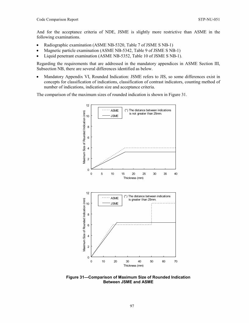
Code Comparison Report STP-NU-051
97
And for the acceptance criteria of NDE, JSME is slightly more restrictive than ASME in the following examinations.
• Radiographic examination (ASME NB-5320, Table 7 of JSME S NB-1) • Magnetic particle examination (ASME NB-5342, Table 9 of JSME S NB-1) • Liquid penetrant examination (ASME NB-5352, Table 10 of JSME S NB-1).
Regarding the requirements that are addressed in the mandatory appendices in ASME Section III, Subsection NB, there are several differences identified as below.
• Mandatory Appendix VI, Rounded Indication: JSME refers to JIS, so some differences exist in concepts for classification of indications, classification of contrast indicators, counting method of number of indications, indication size and acceptance criteria.
The comparison of the maximum sizes of rounded indication is shown in Figure 31.
Figure 31—Comparison of Maximum Size of Rounded Indication Between JSME and ASME
0
2
4
6
8
10
12
0 5 10 15 20 25 30 35 40Thickness (mm)
Max
imum
Size
of R
ound
ed In
dicat
ion
(mm
) ASME
JSME
(*) The distance between indications is not greater than 25mm.
0
2
4
6
8
10
12
0 10 20 30 40 50 60 70Thickness (mm)
Max
imum
Size
of R
ound
ed In
dicat
ion
(mm
) ASME
JSME
(*) The distance between indications is greater than 25mm.
STP-NU-051 Code Comparison Report
98
5.8 Pressure Tests Highlights
• JSME requires pressure testing at 1.1 x PO (operating pressure) if pressure test is conducted between first fuel loading and commercial operation.
Generally, the requirements for testing for Class 1 vessels (NB-6000 in ASME) are almost the same. However, there are some minor differences between JSME and ASME.
First, ASME NB-6114.2 has detailed provisions for substitution of pressure test prior to installation in the system, while JSME PHT-1112.2 does not specify in detail.
Second, JSME requires test pressure as 1.1 x PO (operating pressure) if the pressure test is conducted between first fuel loading and commercial operation (PHT-2111, 2112, 2121 and 2122).
In addition, ASME NB-6222 has different requirements for maximum permissible pressure according to classification of components, while JSME PHT-2130 stipulates the same requirement, 106% of test pressure or stress evaluation for independent classification of components.
JSME PHT-4010 stipulates a different test pressure holding time for valves than ASME NB-6223. (PHT-4010 requires 3 minutes holding time for valves and 10 minutes for other components, while ASME NB-6223 requires 10 minutes for all components.) JSME PHT-3010 stipulates more detailed requirements for components designed for external pressure than ASME NB-6610. (JSME PHT-3010 allows pneumatic test of 1.1 times design pressure besides hydrostatic test of 1.25 times design pressure, while ASME NB-6610 allows hydrostatic test of 1.25 times design pressure only.)
ASME has provisions for machining after pressure test (NB-6115), venting (NB-6211), test medium (NB-6212 and NB-6312), pressure test gauges (NB-6400) and combination units (NB-6620), while JSME does not. ASME NB-6113 has provisions for witnessing of pressure testing, while JSME does not. Again, ISO 9001 is applied for QA requirements in Japan.
5.9 Overpressure Protection Highlights
• JSME only defines design requirements for pressure relief devices, while ASME also defines a set of detailed systems requirements for overpressure protection.
Generally, the requirements for overpressure protection for Class 1 vessels (NB-7000 in ASME) are almost the same. However, there are some minor differences between JSME and ASME.
JSME only specifies design requirements (material, structure, calculation method of relieving capacity, etc.) for pressure relief devices. Many of them refer to JIS. The JSME Code itself does not have equivalent provisions to ASME NB-7000.
JSME has a Code Case for overpressure protection; however, it does not stipulate as many details as ASME.
ASME has provisions for direct spring-loaded valves, pilot operated valves, power-actuated valves as pressure relief valves (NB-7170), while JSME stipulates direct spring-loaded valves only (OPP-2000).
ASME has a provision for an overpressure protection report (NB-7200), while JSME does not.
Both codes specify similar requirements for required number and set pressure of pressure relief devices (NB-7313 and OPP-3000); however, provisions of ASME NB-7313 are more detailed than those of JSME OPP-3000.
Code Comparison Report STP-NU-051
99
ASME NB-7510 stipulates relief valve operating requirements such as set pressure tolerance, while JSME does not. In Japan, JIS is applied for many such requirements.
ASME NB-7700 stipulates several methods for capacity certification, such as flow model test method, coefficient of discharge method, etc., while JSME SRV-3110 stipulates only coefficient of discharge method.
ASME NB-7800 stipulates QA/QC requirements such as stamping and marking, while JSME does not. ISO 9001 is applied for QA requirements in Japan.
5.10 Overview on Quality Aspects Highlights
• No Authorized Inspection and Code Stamping system in JSME like ASME.
In ASME, the QA-related requirements are given in Subsection NCA of Section III and NQA-1. Their counterparts of Japanese Codes are Chapter 1, General Requirements of JSME S-NC1-2008, Rules on Design and Construction for NPPs, Div. 1 LWRs; and JEAC 4111-2003, Code of Quality Assurance for Nuclear Power Plant Safety, which is applicable primarily to plant operation rather than manufacturing.
Generally speaking, the Japanese QA requirements have their basis in ISO 9001-2000 and are performance based, while the ASME requirements are compliance QA. Therefore, there exist significant differences between ASME and JSME (including JEA).
Below is a summary comparison between ASME and JSME on the QA-related requirements.
Starting with the comparison with ASME Subsection NCA, the first difference is related to NCA-1000, SCOPE OF SECTION III. It is not equivalent, but there is no meaningful technical difference between ASME and JSME. For the rest:
(a) NCA-2000, CLASSIFICATION OF COMPONENTS AND SUPPORTS: Not equivalent, but almost no difference for their technical positions.
(b) NCA-3000, RESPONSIBILITIES AND DUTIES: No correspondence in JSME, since Japan has no society's qualification and accreditation system like ASME. Thus, an article corresponding to NCA-3000 is not prepared in JSME Code.
(c) NCA-4000, QUALITY ASSURANCE: In Japan, QA Code applicable to nuclear power plant is established and maintained by JEA (Japan Electric Associated) and endorsed by Regulatory Authority independently from JSME Code. Thus, JSME Code has no article about Quality Assurance corresponding to NCA-4000. Also, the Japanese QA Code, established and maintained by JEA, is based on the “Performance-Base QA” concept of ISO 9001-2000, and has many differences from NCA-4000 and NQA-1-1994, which are based on “Compliance QA” concept.
(d) NCA-5000, AUTHORIZED INSPECTION: Japan has no Authorized Inspection and Code Data Report system like ASME. Thus, the JSME Code has no article about Authorized Inspection corresponding to NCA-5000.
(e) NCA-8000, CERTIFICATES, NAMEPLATES, CODE SYMBOL STAMPING, AND DATA REPORTS: Japan has no Authorized Inspection and Code Stamping system like ASME. Thus, the JSME Code has no article corresponding to NCA-8000.
(f) NCA-9000, GLOSSARY: Not equivalent, but no meaningful technical difference between ASME and JSME.
STP-NU-051 Code Comparison Report
100
Now, turning to the comparison with ASME NQA-1-1994, with regard to the Basic and Supplementary Requirements, there are significant differences. The JEA QA Code, based on the “Performance-Base QA” concept of ISO 9001-2000, is more generic and plain as compared with NQA-1-1994, which is based on the “Compliance QA” concept.
Major differences between NQA-1 and JEA QA Code include:
(a) For 18 Basic Requirements of NQA-1, JEA QA Code is “basically” or “conceptually” equivalent.
(b) For Supplementary Requirements of NQA-1, JEA QA Code has less detailed requirements.
(c) The differences between ASME and JEA Code are especially large in the following three Supplementary Requirements of NQA-1, where NQA-1 gives very detailed procedure requirements.
(1) SUPPLEMENT 3S-1, Supplementary Requirements for Design Control
(2) SUPPLEMENT 7S-1, Supplementary Requirements for Control of Purchased Items and Services
(3) SUPPLEMENT 17S-1, Supplementary Requirements for Quality Assurance Records.
5.11 Conclusion With regard to the rules on materials, design, fabrication, examination, testing and overpressure protection, it was confirmed that the very basic technical requirements are the same between ASME and JSME Codes. Especially, the basic design allowable limits for the failure modes that should be considered in design and for every operating condition are fundamentally identical.
There are, of course, a number of minor differences in the requirements of JSME and ASME Codes. A large part of these differences fall into a category, “ASME requirement that is not addressed or less detailed in JSME,” which reflects the industry’s level of quality activities and technologies in Japan.
Figures 32, 33 and 34 are charts summarizing the similarities and differences based on the comparison results between ASME and JSME Codes given in the Appendix 2. These bar diagrams give a good general picture of the nature and number of similarities and differences between the two codes.
From the similarity and differences of JSME and ASME Codes, it could be concluded that, although there are number of minor differences, JSME Code provides essentially the same level of requirements for Class 1 components as compared to those to ASME Code.
Nevertheless, as described in the previous section, there are differences between ASME and JSME requirements. The sources of these differences are identified and classified as follows.
(a) Utility or manufacturer's own QA program based on ISO 9001 is applied to the QA activities in Japan.
(b) JSME Code (Rules on Design and Construction) was first developed mainly based on MITI Notification No. 501, which contains the detailed technical rules for structural design of nuclear components established by the regulatory authority. In developing MITI Notification No. 501, they sifted through ASME Section III and adopted provisions therein that were judged necessary from the regulator’s point of view. With this background, there are number of provisions that exist in ASME Section III but not in JSME Code.
(c) JSME Code specifies applicable JIS (Japanese Industrial Standards) for base metals, but does not specify those for welding materials. In the JSME Code, specific material specifications are not designated for welding materials. A manufacturer qualifies applicable welding material based on the welding procedure qualification test conducted in accordance with the performance
Code Comparison Report STP-NU-051
101
requirement of Part 2 of JSME S NB1-2007, “Rules on Welding for Nuclear Power Plants.” While MITI Notification No. 501 that is the basis for JSME Code for Design referred to the ASME Code Sec. III, MITI Ordinance No. 81 that is the basis for JSME Code for Welding did not refer to ASME Code Sec. III. The structure of MITI Ordinance No. 81 is different from that of ASME Sec.III. It was developed based on the Japanese industry's experience and includes requirements for thermal power components.
(d) In the Japanese construction activities, inspections by the regulatory authority in the manufacturing stage are limited to welding inspections and shop pressure testing, since, from the standpoint of Japanese regulatory authority, confirmation of Code compliance requirements shall be carried out for completed condition during Japanese style “Stamping” by the regulatory authority and pre-operational testing.
(e) JSME Code SNA-1-2008, “Rules on Fitness-for- Service for Nuclear Power Plants,” which is a JSME counterpart of Section XI, requires performing pre-service examination, but does not have acceptance criteria. This is based on a position that the objective of pre-service examination is to prepare a baseline record for ISI and not to perform evaluation of flaws revealed.
(f) The JSME Code does not have some definitions that are specified in the ASME Code. Definitions are specified according to needs.
(g) The JSME Code may not have provisions for those activities that are ordinarily expected to be performed if not specified.
(h) The JSME Code Committee has made technical judgment to establish the requirements based on available research and development results.
(i) No corresponding (equivalent) provision is made in the JSME Code. Codes and Standards issued by an SDO other than JSME are applied.
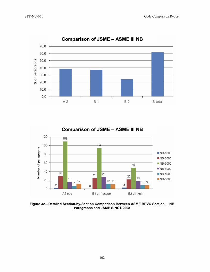
STP-NU-051 Code Comparison Report
102
Figure 32—Detailed Section-by-Section Comparison Between ASME BPVC Section III NB Paragraphs and JSME S-NC1-2008
Comparison of JSME – ASME III NB
Comparison of JSME – ASME III NB
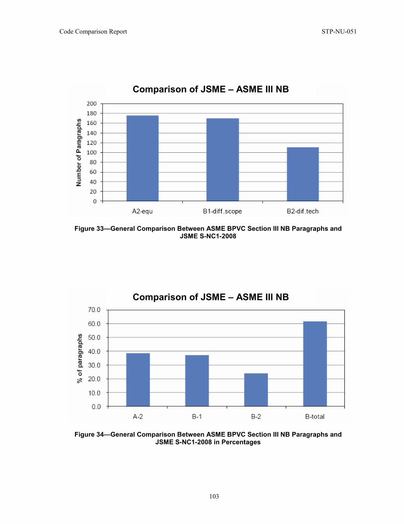
Code Comparison Report STP-NU-051
103
Figure 33—General Comparison Between ASME BPVC Section III NB Paragraphs and JSME S-NC1-2008
Figure 34—General Comparison Between ASME BPVC Section III NB Paragraphs and JSME S-NC1-2008 in Percentages
Comparison of JSME – ASME III NB
Comparison of JSME – ASME III NB
STP-NU-051 Code Comparison Report
104
6 KEPIC VERSUS ASME BPVC SECTION III COMPARISON
6.1 Abstract Nuclear power plants have been continuously constructed in Korea during the three decades since Kori Nuclear Power Plant, the first nuclear power plant built in Korea, started commercial operation in 1978.
Currently, 17 units of PWR types and 4 units of PHWR types are in operation in Korea, and the Shin-Kori, Shin-Wolsung and Shin-Ulchin Nuclear Power Plants are currently being constructed. Nuclear power has become an important energy source in Korea, and is projected to fulfill 34% of total domestic power demand in 2011.
ASME BPVC has been applied to all existing nuclear power plants, with the exception of Ulchin Plants Units 1 and 2, where RCC was applied and Wolsung Units 1 through 4, where CSA was applied. Accordingly, KEPIC has adopted the technical requirements of ASME BPVC without modification, following the spirit of safety of ASME BPVC, and has customized the requirements of system and operation for the local environment.
Thus developed, KEPIC has been applied to all new nuclear power plants under construction, starting with Units 5 and 6 of Ulchin Nuclear Power Plant, and it is also being applied to the construction of the UAE nuclear power plant.
As the global demand for nuclear power increases rapidly during this current nuclear renaissance, a demand for a comparative analysis of major nuclear power plant design codes has been identified, with the focus being the major regulatory institutions of nuclear power countries. A comparison has been conducted on ASME (USA), RCC (France), JSME (Japan), KEPIC (Korea), CSA (Canada), and ENES (Russia), and the differences in codes between each SDO and ASME 2007 edition have been compared and analyzed.
This section contains the results of a comparison of ASME and KEPIC in relation to the safety of nuclear power, Class 1 pressure vessels, piping, pumps, valves, etc. based on a study made over the last several years. As a result, it was found that there was no difference in technical requirements, with the exception of system requirements, and it has been concluded that there are no technical issues in applying equipment manufactured in accordance with KEPIC to nuclear power plants where ASME is applied.
KEA would like that the result provided in this report can be utilized as important data that will enable a better understanding of the differences in the nuclear power plant design codes of the various regulatory institutions of each country, equipment manufacturers, construction companies and certification institutions, and that technical exchanges between SDO of each country can become more active, and that collaboration to promote the safety of nuclear power plants will be increased based on this result.
6.2 Introduction In accordance with the agreement among SDOs participating in TG MDEP, differences of ASME BPVC were noted and closely analyzed with regard to Class 1 components. In the analysis of differences, administrative requirements as well as technical requirements were included. As for the technical requirements, KEPIC-MNB and ASME BPVC Sec. III Div. 1 NB were compared. For administrative requirements, KEPIC-MNA and ASME BPVC Sec. III Div. 1 NCA were compared. With the base of requirements in the ASME BPVC 2007 Edition, corresponding KEPIC 2005 Edition – 2008 2nd Addendum was compared in summary. The requirements of KEPIC-MN deal with piping, pumps and valves, as well as Class 1 pressure vessels, the same as ASME NB, and all the requirements in KEPIC-MNB were compared with the corresponding ASME BPVC. The
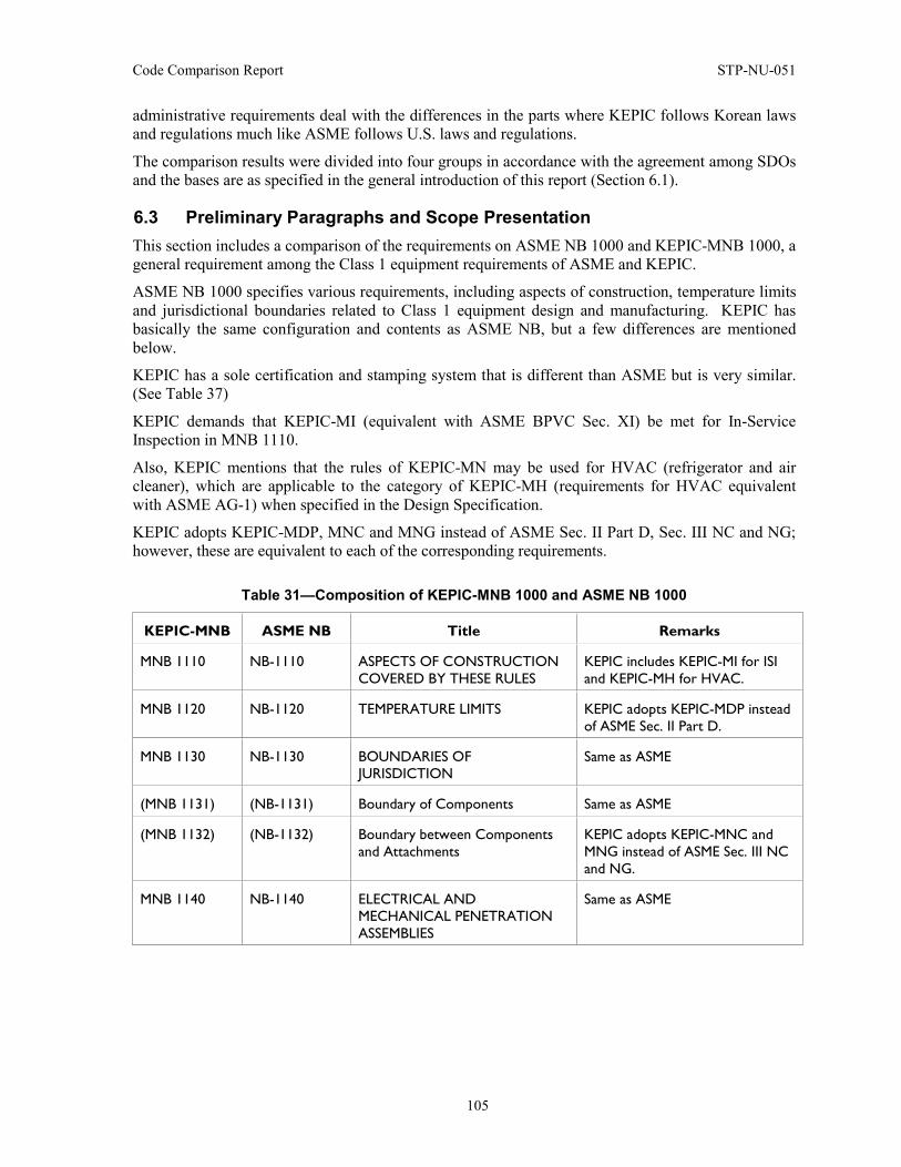
Code Comparison Report STP-NU-051
105
administrative requirements deal with the differences in the parts where KEPIC follows Korean laws and regulations much like ASME follows U.S. laws and regulations.
The comparison results were divided into four groups in accordance with the agreement among SDOs and the bases are as specified in the general introduction of this report (Section 6.1).
6.3 Preliminary Paragraphs and Scope Presentation This section includes a comparison of the requirements on ASME NB 1000 and KEPIC-MNB 1000, a general requirement among the Class 1 equipment requirements of ASME and KEPIC.
ASME NB 1000 specifies various requirements, including aspects of construction, temperature limits and jurisdictional boundaries related to Class 1 equipment design and manufacturing. KEPIC has basically the same configuration and contents as ASME NB, but a few differences are mentioned below.
KEPIC has a sole certification and stamping system that is different than ASME but is very similar. (See Table 37)
KEPIC demands that KEPIC-MI (equivalent with ASME BPVC Sec. XI) be met for In-Service Inspection in MNB 1110.
Also, KEPIC mentions that the rules of KEPIC-MN may be used for HVAC (refrigerator and air cleaner), which are applicable to the category of KEPIC-MH (requirements for HVAC equivalent with ASME AG-1) when specified in the Design Specification.
KEPIC adopts KEPIC-MDP, MNC and MNG instead of ASME Sec. II Part D, Sec. III NC and NG; however, these are equivalent to each of the corresponding requirements.
Table 31—Composition of KEPIC-MNB 1000 and ASME NB 1000
KEPIC-MNB ASME NB Title Remarks
MNB 1110 NB-1110 ASPECTS OF CONSTRUCTION COVERED BY THESE RULES
KEPIC includes KEPIC-MI for ISI and KEPIC-MH for HVAC.
MNB 1120 NB-1120 TEMPERATURE LIMITS KEPIC adopts KEPIC-MDP instead of ASME Sec. II Part D.
MNB 1130 NB-1130 BOUNDARIES OF JURISDICTION
Same as ASME
(MNB 1131) (NB-1131) Boundary of Components Same as ASME
(MNB 1132) (NB-1132) Boundary between Components and Attachments
KEPIC adopts KEPIC-MNC and MNG instead of ASME Sec. III NC and NG.
MNB 1140 NB-1140 ELECTRICAL AND MECHANICAL PENETRATION ASSEMBLIES
Same as ASME
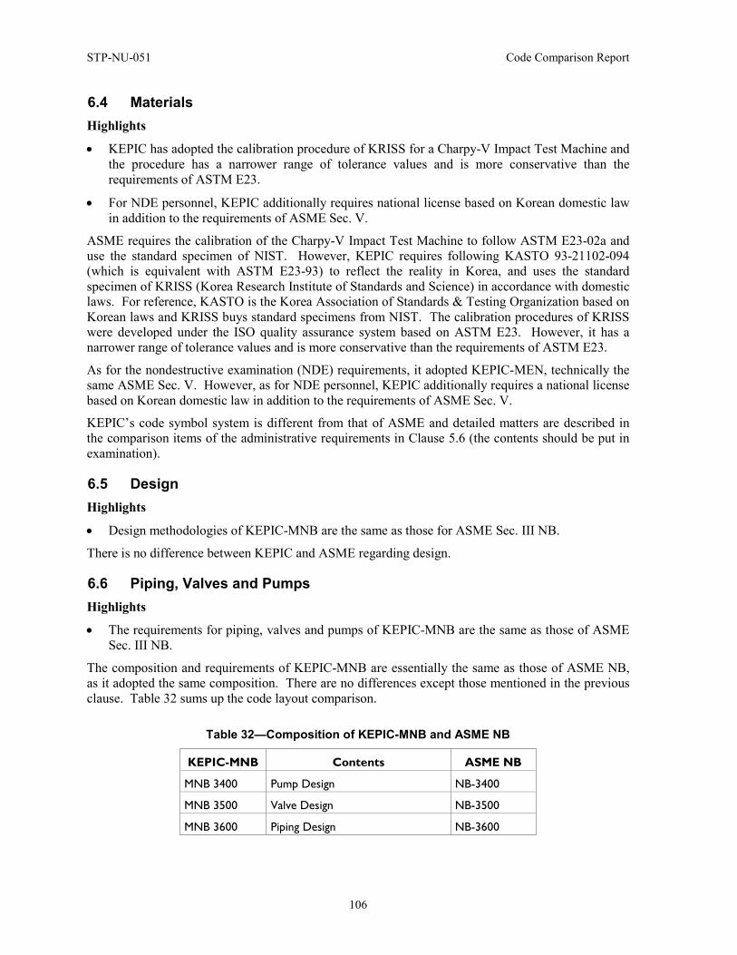
STP-NU-051 Code Comparison Report
106
6.4 Materials Highlights
• KEPIC has adopted the calibration procedure of KRISS for a Charpy-V Impact Test Machine and the procedure has a narrower range of tolerance values and is more conservative than the requirements of ASTM E23.
• For NDE personnel, KEPIC additionally requires national license based on Korean domestic law in addition to the requirements of ASME Sec. V.
ASME requires the calibration of the Charpy-V Impact Test Machine to follow ASTM E23-02a and use the standard specimen of NIST. However, KEPIC requires following KASTO 93-21102-094 (which is equivalent with ASTM E23-93) to reflect the reality in Korea, and uses the standard specimen of KRISS (Korea Research Institute of Standards and Science) in accordance with domestic laws. For reference, KASTO is the Korea Association of Standards & Testing Organization based on Korean laws and KRISS buys standard specimens from NIST. The calibration procedures of KRISS were developed under the ISO quality assurance system based on ASTM E23. However, it has a narrower range of tolerance values and is more conservative than the requirements of ASTM E23.
As for the nondestructive examination (NDE) requirements, it adopted KEPIC-MEN, technically the same ASME Sec. V. However, as for NDE personnel, KEPIC additionally requires a national license based on Korean domestic law in addition to the requirements of ASME Sec. V.
KEPIC’s code symbol system is different from that of ASME and detailed matters are described in the comparison items of the administrative requirements in Clause 5.6 (the contents should be put in examination).
6.5 Design Highlights
• Design methodologies of KEPIC-MNB are the same as those for ASME Sec. III NB.
There is no difference between KEPIC and ASME regarding design.
6.6 Piping, Valves and Pumps Highlights
• The requirements for piping, valves and pumps of KEPIC-MNB are the same as those of ASME Sec. III NB.
The composition and requirements of KEPIC-MNB are essentially the same as those of ASME NB, as it adopted the same composition. There are no differences except those mentioned in the previous clause. Table 32 sums up the code layout comparison.
Table 32—Composition of KEPIC-MNB and ASME NB
KEPIC-MNB Contents ASME NB
MNB 3400 Pump Design NB-3400
MNB 3500 Valve Design NB-3500
MNB 3600 Piping Design NB-3600
Code Comparison Report STP-NU-051
107
6.7 Fabrication – Welding Highlights
• Fabrication requirements of KEPIC-MNB are same with ASME Sec. III NB.
• KEPIC and ASME require t min. for the counterbore length of fittings for pre-service inspection (PSI), but KEPIC allows 0.5-inch counterbore length for fittings in Code Case.
There is no significant difference between KEPIC and ASME regarding fabrication. For reference, ASME requires t min. for the counterbore length of fittings for PSI, which is an additional requirement to acquire more NDE signals during the test conducted during the operation added after ASME BPVC 1995. This does not affect matters related to safety. Before then, the counterbore length of fittings was not separately specified even in ASME BPVC.
In any event, the related requirements of KEPIC are the same as ASME. However, in 2009 (comparing only up to 2007 Edition), the counterbore length of fittings of 0.5 inch was enabled with the Code Case, which shall be applied through an agreement with the regulatory organization. Korea has been building existing power plants by applying 0.5 inch, and has proven that it has not affected safety based on continued construction and operation of the power plants.
6.8 Examination Highlights
• NDE personnel qualification is different as they follow different requirements.
Regarding the PSI, KEPIC-MNA does not adopt the fracture mechanics data required by ASME NCA3252 (a) (6).
Regarding the certification of NDE personnel, ASME requires following ASNT SNT-TC-1A within the requirements of NB. However, as ASNT SNT-TC-1A is adopted in KEPIC-MEN, the NDE requirements, KEPIC-MNB, must follow KEPIC-MEN.
6.9 Pressure Tests There is no difference between KEPIC and ASME with regard to the tests.
6.10 Overpressure Protection Highlights
• Personnel qualification follows KEPIC-QAR.
The terminology “NV Certification Holder,” which is used in ASME requirements, is expressed as “Pressure Relief Valve Manufacturer” in KEPIC, operating a different code symbol system from ASME.
ASME requires following Sec. III Appendix XXIII for Personnel Qualification with regard to the Certification of the Overpressure Protection Report. However, KEPIC requires following KEPIC’s equivalent KEPIC-QAR. KEPIC-QAR has the same basic contents as Sec. III Appendix XXIII. However, in terms of matters regarding national certification, the Korean national education system and qualification system are applied as shown in Table 33.
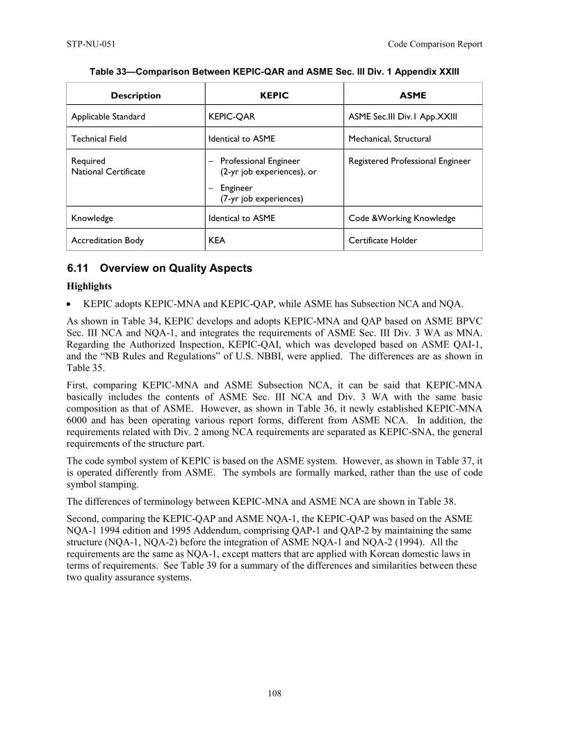
STP-NU-051 Code Comparison Report
108
Table 33—Comparison Between KEPIC-QAR and ASME Sec. III Div. 1 Appendix XXIII
Description KEPIC ASME
Applicable Standard KEPIC-QAR ASME Sec.III Div.1 App.XXIII
Technical Field Identical to ASME Mechanical, Structural
Required National Certificate
– Professional Engineer (2-yr job experiences), or
– Engineer (7-yr job experiences)
Registered Professional Engineer
Knowledge Identical to ASME Code &Working Knowledge
Accreditation Body KEA Certificate Holder
6.11 Overview on Quality Aspects Highlights
• KEPIC adopts KEPIC-MNA and KEPIC-QAP, while ASME has Subsection NCA and NQA.
As shown in Table 34, KEPIC develops and adopts KEPIC-MNA and QAP based on ASME BPVC Sec. III NCA and NQA-1, and integrates the requirements of ASME Sec. III Div. 3 WA as MNA. Regarding the Authorized Inspection, KEPIC-QAI, which was developed based on ASME QAI-1, and the “NB Rules and Regulations” of U.S. NBBI, were applied. The differences are as shown in Table 35.
First, comparing KEPIC-MNA and ASME Subsection NCA, it can be said that KEPIC-MNA basically includes the contents of ASME Sec. III NCA and Div. 3 WA with the same basic composition as that of ASME. However, as shown in Table 36, it newly established KEPIC-MNA 6000 and has been operating various report forms, different from ASME NCA. In addition, the requirements related with Div. 2 among NCA requirements are separated as KEPIC-SNA, the general requirements of the structure part.
The code symbol system of KEPIC is based on the ASME system. However, as shown in Table 37, it is operated differently from ASME. The symbols are formally marked, rather than the use of code symbol stamping.
The differences of terminology between KEPIC-MNA and ASME NCA are shown in Table 38.
Second, comparing the KEPIC-QAP and ASME NQA-1, the KEPIC-QAP was based on the ASME NQA-1 1994 edition and 1995 Addendum, comprising QAP-1 and QAP-2 by maintaining the same structure (NQA-1, NQA-2) before the integration of ASME NQA-1 and NQA-2 (1994). All the requirements are the same as NQA-1, except matters that are applied with Korean domestic laws in terms of requirements. See Table 39 for a summary of the differences and similarities between these two quality assurance systems.
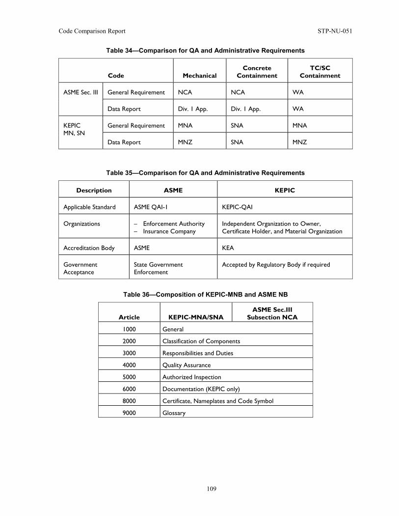
Code Comparison Report STP-NU-051
109
Table 34—Comparison for QA and Administrative Requirements
Code Mechanical Concrete
Containment TC/SC
Containment
ASME Sec. III General Requirement NCA NCA WA
Data Report Div. 1 App. Div. 1 App. WA
KEPIC MN, SN
General Requirement MNA SNA MNA
Data Report MNZ SNA MNZ
Table 35—Comparison for QA and Administrative Requirements
Description ASME KEPIC
Applicable Standard ASME QAI-1 KEPIC-QAI
Organizations – Enforcement Authority – Insurance Company
Independent Organization to Owner, Certificate Holder, and Material Organization
Accreditation Body ASME KEA
Government Acceptance
State Government Enforcement
Accepted by Regulatory Body if required
Table 36—Composition of KEPIC-MNB and ASME NB
Article KEPIC-MNA/SNA ASME Sec.III
Subsection NCA
1000 General
2000 Classification of Components
3000 Responsibilities and Duties
4000 Quality Assurance
5000 Authorized Inspection
6000 Documentation (KEPIC only)
8000 Certificate, Nameplates and Code Symbol
9000 Glossary
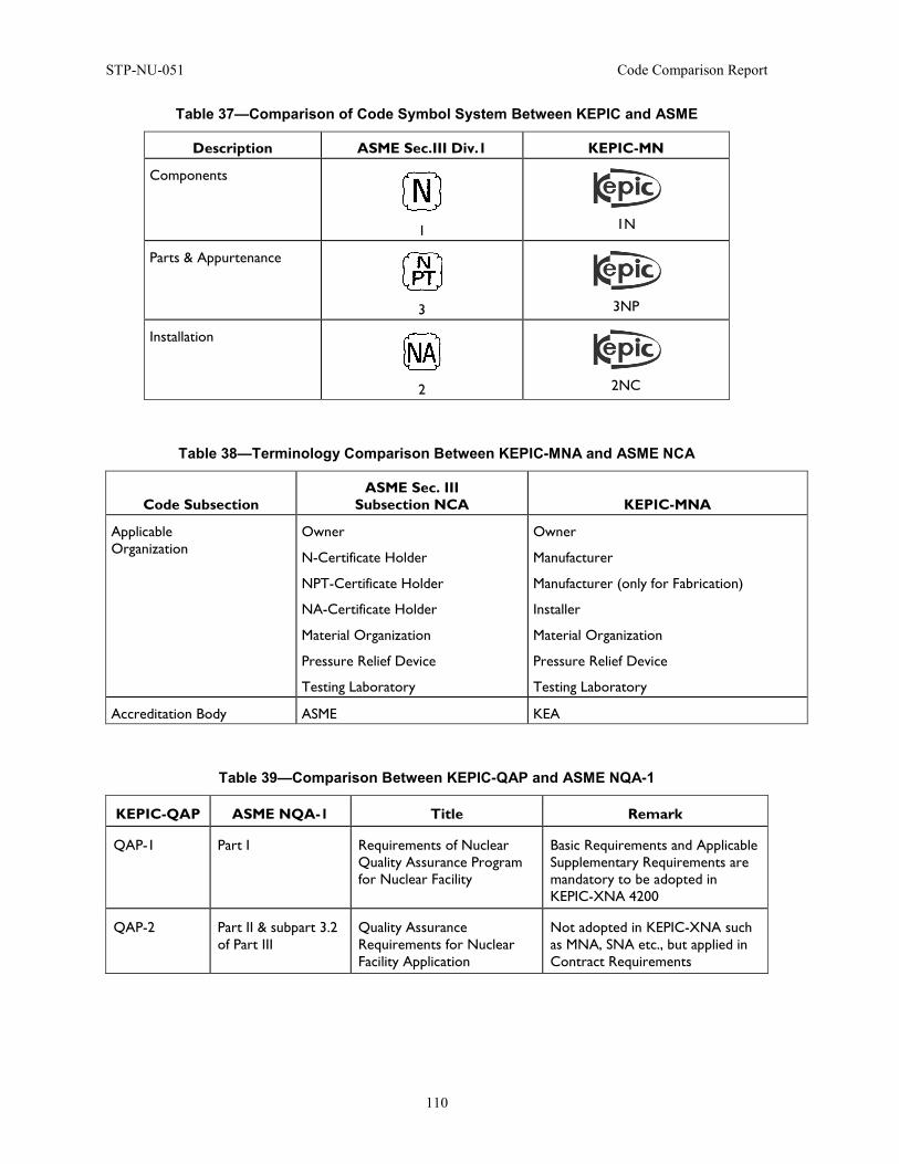
STP-NU-051 Code Comparison Report
110
Table 37—Comparison of Code Symbol System Between KEPIC and ASME
Description ASME Sec.III Div.1 KEPIC-MN
Components
1
1N
Parts & Appurtenance
3
3NP
Installation
2
2NC
Table 38—Terminology Comparison Between KEPIC-MNA and ASME NCA
Code Subsection ASME Sec. III
Subsection NCA KEPIC-MNA
Applicable Organization
Owner
N-Certificate Holder
NPT-Certificate Holder
NA-Certificate Holder
Material Organization
Pressure Relief Device
Testing Laboratory
Owner
Manufacturer
Manufacturer (only for Fabrication)
Installer
Material Organization
Pressure Relief Device
Testing Laboratory
Accreditation Body ASME KEA
Table 39—Comparison Between KEPIC-QAP and ASME NQA-1
KEPIC-QAP ASME NQA-1 Title Remark
QAP-1 Part I Requirements of Nuclear Quality Assurance Program for Nuclear Facility
Basic Requirements and Applicable Supplementary Requirements are mandatory to be adopted in KEPIC-XNA 4200
QAP-2 Part II & subpart 3.2 of Part III
Quality Assurance Requirements for Nuclear Facility Application
Not adopted in KEPIC-XNA such as MNA, SNA etc., but applied in Contract Requirements
Code Comparison Report STP-NU-051
111
6.12 Conclusion So far, KEPIC-MNB, the requirements for Class 1 pressure vessels, pumps, pipes, etc., has followed the spirit of ASME safety in terms of technical matters, and there are no technical differences.
In addition, in terms of QA and the administrative requirements related with nuclear safety, KEPIC-MNB adopted and has operated the requirements of ASME in most of the parts. However, it reflected the differences resulting from different laws and regulations and education systems in Korea from those of the U.S.A. KEPIC introduced ASME’s code symbol system and operates independent code symbol systems through simplification. However, there are no requirements to have been relaxed from ASME levels regarding safety.
Thus far, the differences between KEPIC and ASME BPVC with regard to Class 1 component-related requirements have been analyzed. In addition, the differences in QA and administrative requirements have been noted. As explained above, KEPIC-MN has the same technical matters, as it adopted the same contents of the technical requirements of ASME BPVC NB by adopting them unchanged.
In terms of the systematic parts, both have the same basic contents. However, KEPIC tried to be more subjective relating to the regulations with regard to nuclear power safety, system operation, qualification entitlement, etc. regulations, by naturally applying Korean domestic laws, albeit through the same basic frameworks.
In conclusion, KEPIC and ASME have no noticeable differences as regards nuclear safety. Class 1 components designed and manufactured in accordance with KEPIC-MNB can be applied in the power plant construction projects that are applied with ASME BPVC Sec. III.
KEA aims to establish various cooperative relationships with ASME, such as endorsing both parties of certificate holders under KEPIC or ASME.
STP-NU-051 Code Comparison Report
112
7 CSA VERSUS ASME BPVC SECTION III COMPARISON
7.1 Abstract The Canadian and American nuclear industries are organized around different reactor concepts and have developed construction rules specific to each type. The CSA Standards reference the ASME BPVC and its requirements where applicable. The CSA Standards specify requirements for the materials, design, fabrication, installation, quality assurance and inspection of those pressure-retaining components and supports that are not covered by the ASME BPVC. This section attempts to provide a comprehensive comparison between the Canadian CSA Standard N285.0-08 and the ASME BPVC Section III.
7.2 Introduction In Canada, all nuclear reactors for power production are of the CANDU design at this time. The CANDU reactor is a pressurized heavy water reactor that makes use of multiple horizontal Zircaloy pressure tubes, through which the pressurized heavy water coolant flows over fuel bundles, removing the heat of the fission reaction. In contrast, the fuel in pressurized water reactor (PWR) and boiling water reactor (BWR) reactor designs is located in a single large pressure vessel through which the coolant flows over the fuel. The CSA N285.0 Standard was developed to accommodate those unique features of the CANDU concept not addressed in ASME BPVC Section III, which was developed based on the PWR and BWR concepts.
The requirements of the CSA N285.0 Standard are directed to the licensee. It contains requirements that are wider in Scope than ASME Section III. In many ways, it acts as an intermediate document between the Regulatory requirements and the component. It places the responsibility for adherence to the requirements on the Licensee, even though the actual performance of much of the work is done by others. ASME Section III, on the other hand, is directed to the construction of components only and places the responsibility for adherence to the requirements on the Certificate Holders defined in Section III. However through N285.0, direct reference to the requirements of ASME Section III Div.1, it achieves indirectly many results identical to Section III.
The CSA N285.0 Standard specifies the technical requirements for the design, procurement, fabrication, installation, modification, repair, replacement, testing, examination and inspection of, and other work related to, pressure-retaining and containment systems, components and supports over the service life of a CANDU nuclear power plant.
This Standard applies to all pressure-retaining systems, including their components and supports, in a CANDU nuclear power plant.
This Standard applies to containment components, but does not apply to concrete containment structures.
This Standard does not apply to portable assemblies of pressurized items that are temporarily connected to a system or component to enable testing, venting, draining, calibration or other maintenance activities, provided that they do not reduce the ability of a special safety system or safety-related system to perform its design safety function; are under surveillance when connected and are removed upon completion of their function; and are constructed to Standards deemed by the licensee to be suitable for the application.
Code Comparison Report STP-NU-051
113
7.3 Preliminary Paragraphs and Scope Presentation The requirements of the CSA Standard N285.0 are wider in scope than in ASME BPVC Section III. CSA Standard N285.0 places the responsibility for adherence to the requirements on the Licensee even though the actual performance of the work is done by others. The ASME BPVC Section III is intended for the construction of components only and places the responsibility for adherence to the requirements on the Certificate Holder identified in the Code.
CSA Standard N285.0 is an intermediate document between the Regulatory requirements and the construction of the component. CSA Standard N285.0 specifies the technical requirements for the design, procurement, fabrication, installation, modification, repair, replacement, testing, examination and inspection of, and other work related to, pressure-retaining and containment systems, components and supports over the life-cycle of a CANDU Nuclear Power Plant. This Standard includes metal containment components that are part of the containment system but does not apply to the concrete containment structures. This is covered by the CSA N287 Series.
This Standard does not apply to portable assemblies of pressurized items that are temporarily connected to a system or component to enable testing, venting, draining, calibration or other maintenance activities, provided that they:
(a) do not reduce the ability of a special safety system or safety-related system to perform its design safety function;
(b) are under surveillance when connected and are removed upon completion of their function; and
(c) are constructed to Standards deemed by the licensee to be suitable for the application.
As noted above, some aspects of the CANDU reactor design concepts are different than the light water reactor (LWR) concepts (PWR/BWR) for which the ASME BPVC Section III was developed. The most significant difference is associated with the reactor vessel rather than with the associated equipment such as the vessels, pumps, valves and piping systems. The CANDU concept has resulted in special materials and components not covered by the ASME BPVC Section III requirements.
CSA Standard N285.0-08, Annex I covers the construction requirements for components unique to the CANDU design. The requirements for the special Zirconium material properties used for the components are covered by the specifications in CSA Standard N285.6. This Standard also includes a specification for the material, CSA G40, commonly used for supports in CANDU design. This specification has not been adopted by ASME BPVC Section III; however, this material specification has properties that are similar to SA-56.
Another area not covered directly by the ASME BPVC Section III is the metallic components associated with containment systems. CSA Standard N285.0 has developed Annex J to cover these items.
Classification of Components
In Canada, the rules for classification of systems are provided in the CSA Standard N285.0-08; Clause 5.0 and Annex A. Once the system has been classified, the components adopt the classification of the system. The component is then constructed to the requirements of the ASME BPVC Section III except those items that are unique to the CANDU concept. The construction requirements for these items are covered in Annex I of the CSA Standard N285.0-08. The CANDU components receive a unique classification to identify them as having specific construction requirements outside the scope of ASME BPVC Section III. For example, a CANDU component in a Class 1 system will be classified as Class 1C.
The requirements for the CANDU Containment System are different from the ASME BPVC Section III requirements. The concrete portions of the Containment Systems for CANDU reactors are
STP-NU-051 Code Comparison Report
114
covered by the CSA Standards in the CSA N287 Series. ASME BPVC Section III addresses concrete containment in Division 2. The metallic portions of the Containment System are covered by Annex J of the CSA Standard N285.0-08. The classification of these metallic components is referred to as a Class 4 item.
Annexes I and J often refer back to ASME BPVC Section III with guidance on the application of the requirements in the referenced portion of the ASME BPVC Section III to these CANDU items.
Conformity Assessment
CSA has adopted a conformity assessment approach very similar to the requirements of the ASME BPVC Section III. Construction of components must be controlled under a Quality Assurance Program that satisfies the requirements of ASME BPVC Section III and that the requirements for Authorized Inspection are met including the use of nameplates and the issuance of data reports. The required level of conformance to the ASME BPVC Section III requirements is very high.
There is, however, no requirement for the components used in Canada to be stamped. The qualification of the quality programs is done by organizations acceptable to the Regulatory Authority. This is usually the Provincial authority with responsibility for the non-nuclear boilers and pressure vessels that usually perform the authorized inspection duties for non-nuclear equipment. A Certificate is issued by these organizations to indicate the successful implementation of the quality assurance program required by CSA Standard N285.0-08 for the construction of nuclear components. In Canada, there is no requirement for a Certificate of Authorization for the Owner as required in ASME BPVC Section III.
Requirements for Instrumentation and Instrument Lines
The design of sensing elements of instruments is outside the scope of the Standard, except that when an instrument is included in the design of a system, the system designer shall ensure that the pressure boundary of the sensing element is rated for the design conditions of the system. Instruments are treated as fittings and the registration of their design is required by CSA Standard N285.0-08.
Instruments included in the design of a system and that have an inlet larger than NPS 3/4 and a pressure boundary that is subject to the system flow have to meet the requirements associated with the classification of the system.
The pressure boundary portion of instrument systems or components that have an inlet of NPS 3/4 and smaller may be treated as non-nuclear fittings.
Instrument lines for process systems or safety systems have to meet the requirements for the classification of the system to which they are attached, except instrument lines NPS 3/4 and smaller may be constructed in accordance with the requirements for non-nuclear instrumentation unless they are associated with the control of systems that cool the fuel.
Design Registration
The CSA Standard N285.0-08 requires the pressure boundary design for each item be registered. Welding Procedures are also required to be registered in Canada. This is effectively an approval process and registration numbers are issued for each item registered. This is a process that has carried over from the non-nuclear pressure boundary requirements and is intricately wound into the administrative system associated with the Authorized Inspection. ASME recognizes this process by providing a field on the Date Reports for the insertion of the Canadian Registration Number (CRN), although there are no requirements for Registration of designs in ASME BPVC Section III or any other Sections of the ASME BPVC.
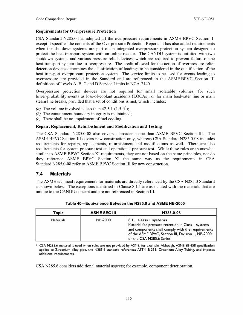
Code Comparison Report STP-NU-051
115
Requirements for Overpressure Protection
CSA Standard N285.0 has adopted all the overpressure requirements in ASME BPVC Section III except it specifies the contents of the Overpressure Protection Report. It has also added requirements when the shutdown systems are part of an integrated overpressure protection system designed to protect the heat transport system with an online reactor. The CANDU system is outfitted with two shutdown systems and various pressure-relief devices, which are required to prevent failure of the heat transport system due to overpressure. The credit allowed for the action of overpressure-relief detection devices determines the classification of loadings to be considered in the qualification of the heat transport overpressure protection system. The service limits to be used for events leading to overpressure are provided in the Standard and are referenced in the ASME BPVC Section III definitions of Levels A, B, C and D Service Limits in NCA-2140.
Overpressure protection devices are not required for small isolatable volumes, for such lower-probability events as loss-of-coolant accidents (LOCAs), or for main feedwater line or main steam line breaks, provided that a set of conditions is met, which includes:
(a) The volume involved is less than 42.5 L (1.5 ft3); (b) The containment boundary integrity is maintained; (c) There shall be no impairment of fuel cooling.
Repair, Replacement, Refurbishment and Modification and Testing
The CSA Standard N285.0-08 also covers a broader scope than ASME BPVC Section III. The ASME BPVC Section III covers new construction only, whereas CSA Standard N285.0-08 includes requirements for repairs, replacements, refurbishment and modifications as well. There are also requirements for system pressure test and operational pressure test. While these rules are somewhat similar to ASME BPVC Section XI requirements, they are not based on the same principles, nor do they reference ASME BPVC Section XI the same way as the requirements in CSA Standard N285.0-08 refer to ASME BPVC Section III for new construction.
7.4 Materials The ASME technical requirements for materials are directly referenced by the CSA N285.0 Standard as shown below. The exceptions identified in Clause 8.1.1 are associated with the materials that are unique to the CANDU concept and are not referenced in Section III.
Table 40—Equivalence Between the N285.0 and ASME NB-2000
Topic ASME SEC III N285.0-08
Materials NB-2000 8.1.1 Class 1 systems Material for pressure retention in Class 1 systems and components shall comply with the requirements of the ASME BPVC, Section III, Division 1, NB-2000, or the CSA N285.6 Series.
* CSA N285.6 material is used when rules are not provided by ASME, for example: Although, ASME SB-658 specification applies to Zirconium alloy pipe, the N285.6 standard references ASTM B-353, Zirconium Alloy Tubing, and imposes additional requirements.
CSA N285.6 considers additional material aspects; for example, component deterioration.
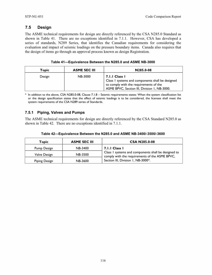
STP-NU-051 Code Comparison Report
116
7.5 Design The ASME technical requirements for design are directly referenced by the CSA N285.0 Standard as shown in Table 41. There are no exceptions identified in 7.1.1. However, CSA has developed a series of standards, N289 Series, that identifies the Canadian requirements for considering the evaluation and impact of seismic loadings on the pressure boundary items. Canada also requires that the design of items go through an approval process known as design Registration.
Table 41—Equivalence Between the N285.0 and ASME NB-3000
Topic ASME SEC III N285.0-08
Design NB-3000 7.1.1 Class 1 Class 1 systems and components shall be designed to comply with the requirements of the ASME BPVC, Section III, Division 1, NB-3000.
* In addition to the above, CSA N285.0-08, Clause 7.1.8 – Seismic requirements states: When the system classification list or the design specification states that the effect of seismic loadings is to be considered, the licensee shall meet the system requirements of the CSA N289 series of Standards.
7.5.1 Piping, Valves and Pumps The ASME technical requirements for design are directly referenced by the CSA Standard N285.0 as shown in Table 42. There are no exceptions identified in 7.1.1.
Table 42—Equivalence Between the N285.0 and ASME NB-3400/-3500/-3600
Topic ASME SEC III CSA N285.0-08
Pump Design NB-3400 7.1.1 Class 1 Class 1 systems and components shall be designed to comply with the requirements of the ASME BPVC, Section III, Division 1, NB-3000*.
Valve Design NB-3500
Piping Design NB-3600
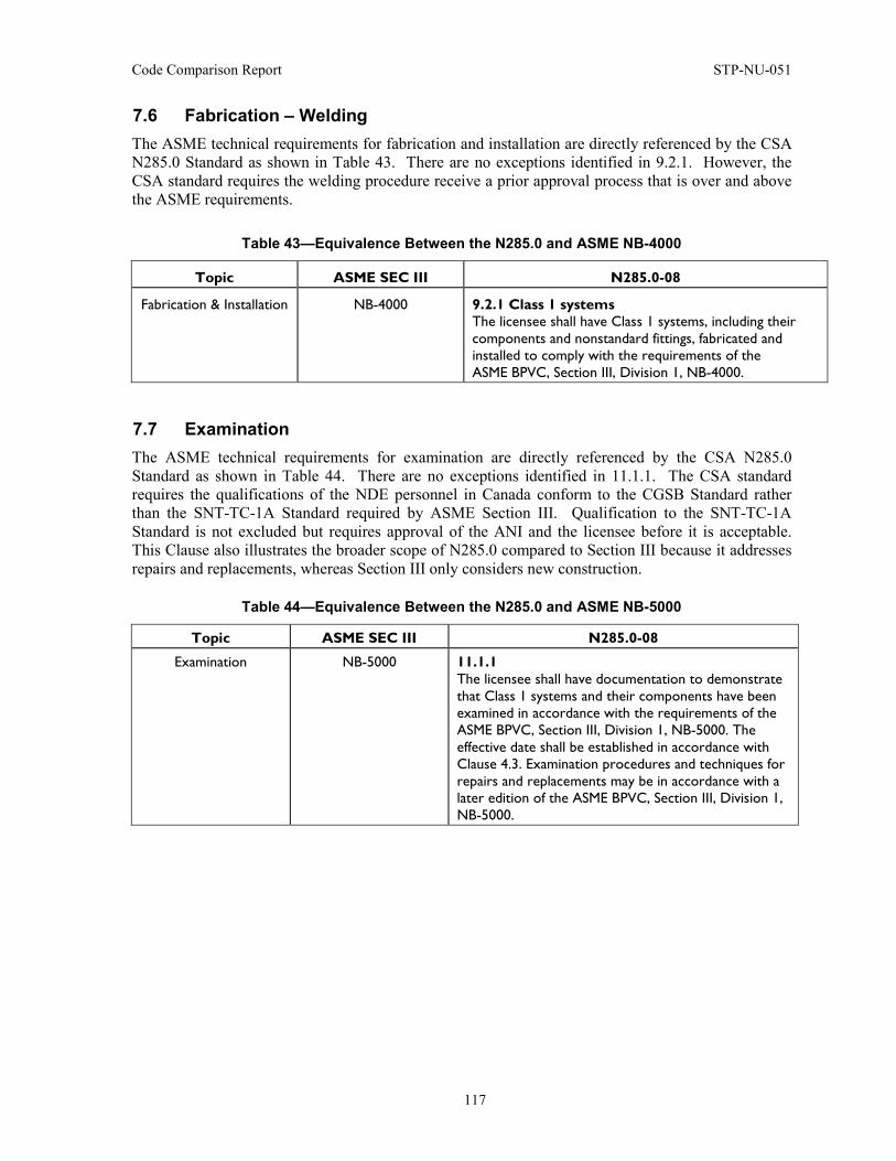
Code Comparison Report STP-NU-051
117
7.6 Fabrication – Welding The ASME technical requirements for fabrication and installation are directly referenced by the CSA N285.0 Standard as shown in Table 43. There are no exceptions identified in 9.2.1. However, the CSA standard requires the welding procedure receive a prior approval process that is over and above the ASME requirements.
Table 43—Equivalence Between the N285.0 and ASME NB-4000
Topic ASME SEC III N285.0-08
Fabrication & Installation NB-4000 9.2.1 Class 1 systems The licensee shall have Class 1 systems, including their components and nonstandard fittings, fabricated and installed to comply with the requirements of the ASME BPVC, Section III, Division 1, NB-4000.
7.7 Examination The ASME technical requirements for examination are directly referenced by the CSA N285.0 Standard as shown in Table 44. There are no exceptions identified in 11.1.1. The CSA standard requires the qualifications of the NDE personnel in Canada conform to the CGSB Standard rather than the SNT-TC-1A Standard required by ASME Section III. Qualification to the SNT-TC-1A Standard is not excluded but requires approval of the ANI and the licensee before it is acceptable. This Clause also illustrates the broader scope of N285.0 compared to Section III because it addresses repairs and replacements, whereas Section III only considers new construction.
Table 44—Equivalence Between the N285.0 and ASME NB-5000
Topic ASME SEC III N285.0-08
Examination NB-5000 11.1.1 The licensee shall have documentation to demonstrate that Class 1 systems and their components have been examined in accordance with the requirements of the ASME BPVC, Section III, Division 1, NB-5000. The effective date shall be established in accordance with Clause 4.3. Examination procedures and techniques for repairs and replacements may be in accordance with a later edition of the ASME BPVC, Section III, Division 1, NB-5000.
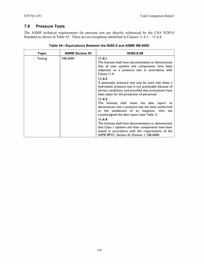
STP-NU-051 Code Comparison Report
118
7.8 Pressure Tests The ASME technical requirements for pressure test are directly referenced by the CSA N285.0 Standard as shown in Table 45. There are no exceptions identified in Clauses 11.4.1 – 11.4.4.
Table 45—Equivalence Between the N285.0 and ASME NB-6000
Topic ASME Section III N285.0-08 Testing NB-6000 11.4.1
The licensee shall have documentation to demonstrate that all new systems and components have been subjected to a pressure test in accordance with Clause 11.4. 11.4.2 A pneumatic pressure test may be used only when a hydrostatic pressure test is not practicable because of service conditions, and provided that precautions have been taken for the protection of personnel. 11.4.3 The licensee shall retain the data report to demonstrate that a pressure test has been performed to the satisfaction of an inspector, who has countersigned the data report (see Table 1). 11.4.4 The licensee shall have documentation to demonstrate that Class 1 systems and their components have been tested in accordance with the requirements of the ASME BPVC, Section III, Division 1, NB-6000.
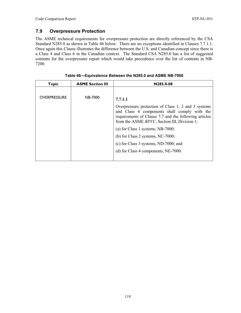
Code Comparison Report STP-NU-051
119
7.9 Overpressure Protection The ASME technical requirements for overpressure protection are directly referenced by the CSA Standard N285.0 as shown in Table 46 below. There are no exceptions identified in Clauses 7.7.1.1. Once again this Clause illustrates the difference between the U.S. and Canadian concept since there is a Class 4 and Class 6 in the Canadian context. The Standard CSA N285.0 has a list of suggested contents for the overpressure report which would take precedence over the list of contents in NB-7200.
Table 46—Equivalence Between the N285.0 and ASME NB-7000
Topic ASME Section III N285.0-08
OVERPRESSURE
NB-7000
7.7.1.1
Overpressure protection of Class 1, 2 and 3 systems and Class 4 components shall comply with the requirements of Clause 7.7 and the following articles from the ASME BPVC, Section III, Division 1:
(a) for Class 1 systems, NB-7000;
(b) for Class 2 systems, NC-7000;
(c) for Class 3 systems, ND-7000; and
(d) for Class 4 components, NE-7000.

STP-NU-051 Code Comparison Report
120
7.10 Overview on Quality Aspects CSA N285.0 calls up the Section III Quality Assurance program for construction of new components. The requirement to meet NCA-3800 for materials does permit the use of other quality assurance programs provided certain added requirements in NCA-3800 are met. These are identified in the detailed Appendix.
Table 47— Equivalence Between the N285.0 and ASME NCA-4000
Topic ASME Section III N285.0-08
Quality Assurance NCA-4000 10.3 Activities undertaken by a contractor Activities performed by a contractor or a licensee acting as a contractor associated with procurement, design, fabrication, installation, modification, replacement, or repair shall meet the following requirements:
(a) For Class 1, 1C, 2, 2C, 3, 3C or 4 systems, components, and supports, activities shall be carried out under a quality assurance program that satisfies the requirements of the ASME BPVC, Section III, Division 1, NCA-4000.
10.4 Activities undertaken by a material organization Activities performed by a material organization or a licensee acting as a material organization associated with the manufacture or supply of materials for use in Class 1, 1C, 2, 2C, 3, 3C or 4 systems or components (including welding consumables) shall meet one of the following requirements:
(a) activities shall be carried out under a quality program that satisfies the requirements of the ASME BPVC, Section III, Division 1, NCA-3800*;
* Although, other quality standards apply to licensed operating CANDU stations and commercial products and service providers, Class 1 pressure boundary activities must comply with ASME requirements shown above.
7.11 Conclusion Although the comparison of the CSA N285.0 Standard with ASME Section III has identified differences, they are relatively few given the significant volume of requirements. From the Canadian perspective, the implementation of the CSA Standard N285.0 is effectively the implementation of Section III.
It is obvious that the differences result from either different regulatory requirements or technical differences that are a result of the different concepts that are not addressed by Section III. This report identifies the technical differences, which are detailed in Appendix D.
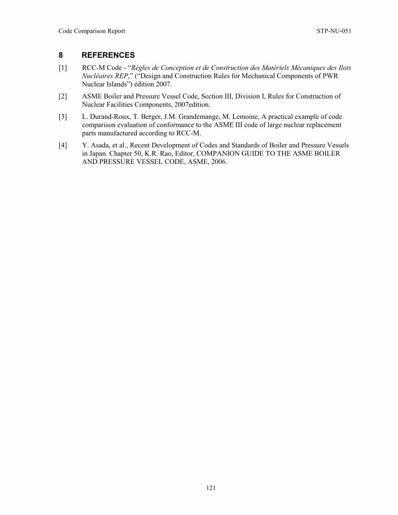
Code Comparison Report STP-NU-051
121
8 REFERENCES [1] RCC-M Code - “Règles de Conception et de Construction des Matériels Mécaniques des Ilots
Nucléaires REP,” (“Design and Construction Rules for Mechanical Components of PWR Nuclear Islands”) édition 2007.
[2] ASME Boiler and Pressure Vessel Code, Section III, Division I, Rules for Construction of Nuclear Facilities Components, 2007edition.
[3] L. Durand-Roux, T. Berger, J.M. Grandemange, M. Lemoine, A practical example of code comparison evaluation of conformance to the ASME III code of large nuclear replacement parts manufactured according to RCC-M.
[4] Y. Asada, et al., Recent Development of Codes and Standards of Boiler and Pressure Vessels in Japan. Chapter 50, K.R. Rao, Editor, COMPANION GUIDE TO THE ASME BOILER AND PRESSURE VESSEL CODE, ASME, 2006.
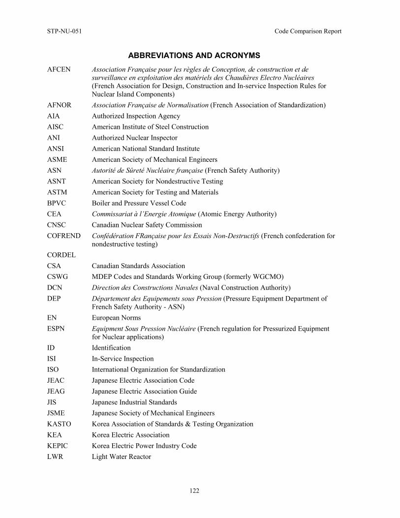
STP-NU-051 Code Comparison Report
122
ABBREVIATIONS AND ACRONYMS AFCEN Association Française pour les règles de Conception, de construction et de
surveillance en exploitation des matériels des Chaudières Electro Nucléaires (French Association for Design, Construction and In-service Inspection Rules for Nuclear Island Components)
AFNOR Association Française de Normalisation (French Association of Standardization) AIA Authorized Inspection Agency AISC American Institute of Steel Construction ANI Authorized Nuclear Inspector ANSI American National Standard Institute ASME American Society of Mechanical Engineers ASN Autorité de Sûreté Nucléaire française (French Safety Authority) ASNT American Society for Nondestructive Testing ASTM American Society for Testing and Materials BPVC Boiler and Pressure Vessel Code CEA Commissariat à l’Energie Atomique (Atomic Energy Authority) CNSC Canadian Nuclear Safety Commission COFREND Confédération FRançaise pour les Essais Non-Destructifs (French confederation for
nondestructive testing) CORDEL CSA Canadian Standards Association CSWG MDEP Codes and Standards Working Group (formerly WGCMO) DCN Direction des Constructions Navales (Naval Construction Authority) DEP Département des Equipements sous Pression (Pressure Equipment Department of
French Safety Authority - ASN) EN European Norms ESPN Equipment Sous Pression Nucléaire (French regulation for Pressurized Equipment
for Nuclear applications) ID Identification ISI In-Service Inspection ISO International Organization for Standardization JEAC Japanese Electric Association Code JEAG Japanese Electric Association Guide JIS Japanese Industrial Standards JSME Japanese Society of Mechanical Engineers KASTO Korea Association of Standards & Testing Organization KEA Korea Electric Association KEPIC Korea Electric Power Industry Code LWR Light Water Reactor
Code Comparison Report STP-NU-051
123
ABBREVIATIONS AND ACRONYMS (cont.) MITI Ministry of International Trade and Industry MDEP Multinational Design Evaluation Programme N/A Not Applicable NDE Non-Destructive Examination NDIS Japanese Society of Non-Destructive Inspection Standards NRC American Nuclear Regulatory Commission NSSC Nuclear Strategic Steering Committee PED European Pressure Equipment Directive PPS Product Procurement Specification, or Part Procurement Specification PQR Procedure of Qualification Record PTC Performance Test Codes PSI Pre-service inspection PWR Pressurized Water Reactor RCC Règles de Conception et de Construction (Design and Construction Rules) RCC-M Règles de Conception et de Construction des Matériels Mécaniques des Ilots
Nucléaires REP (Design and Construction Rules for Mechanical Components of PWR Nuclear Islands)
REP Réacteur à Eau Pressurisée (Pressurized Water Reactor) RPE Registered Professional Engineer RSE Règles de Surveillance en Exploitation (Rules for Safety during Operation) RSE-M Règles de Surveillance en Exploitation des Matériels mécaniques des îlots nucléaires
REP (In-Service Inspection Rules for Mechanical Components of PWR Nuclear Islands)
SDOs Standards Development Organizations SI Système International (International System) STR Spécification Technique de Référence (Technical Reference Specification) TBT Technical Barriers to Trade TC Technical Committee WGCMO MDEP Working Group on Component Manufacturing Oversight WP Welding Procedure WNA World Nuclear Association WPS Weld Procedure Specification WTO World Trade Organization
STP-NU-051 Code Comparison Report
124
APPENDIX A: RCC-M VERSUS ASME SECTION III DETAILED COMPARISON TABLE
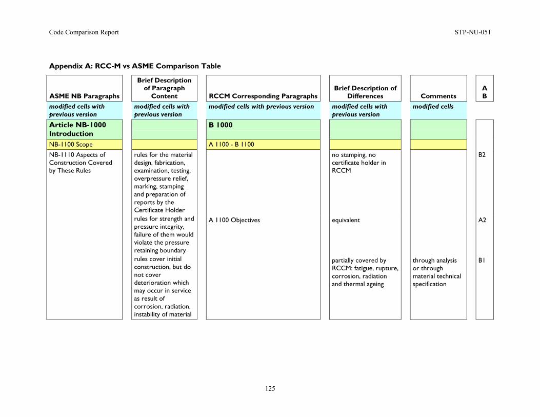
Code Comparison Report STP-NU-051
125
Appendix A: RCC-M vs ASME Comparison Table
ASME NB Paragraphs
Brief Description of Paragraph
Content
RCCM Corresponding Paragraphs
Brief Description of Differences
Comments
A B
modified cells with previous version
modified cells with previous version
modified cells with previous version modified cells with previous version
modified cells
Article NB-1000 Introduction
B 1000
NB-1100 Scope A 1100 - B 1100
NB-1110 Aspects of Construction Covered by These Rules
rules for the material design, fabrication, examination, testing, overpressure relief, marking, stamping and preparation of reports by the Certificate Holder
no stamping, no certificate holder in RCCM
B2
rules for strength and pressure integrity, failure of them would violate the pressure retaining boundary
A 1100 Objectives equivalent A2
rules cover initial construction, but do not cover deterioration which may occur in service as result of corrosion, radiation, instability of material
partially covered by RCCM: fatigue, rupture, corrosion, radiation and thermal ageing
through analysis or through material technical specification
B1
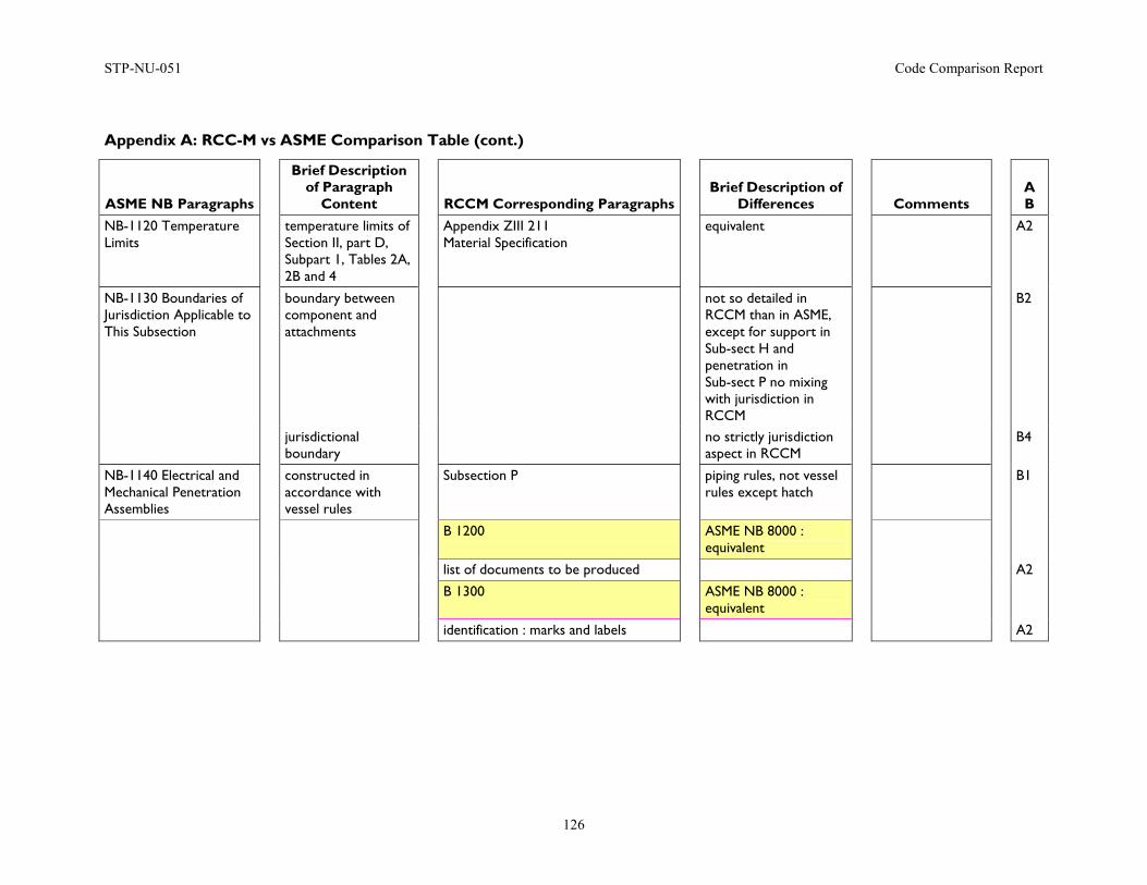
STP-NU-051 Code Comparison Report
126
Appendix A: RCC-M vs ASME Comparison Table (cont.)
ASME NB Paragraphs
Brief Description of Paragraph
Content
RCCM Corresponding Paragraphs
Brief Description of Differences
Comments
A B
NB-1120 Temperature Limits
temperature limits of Section II, part D, Subpart 1, Tables 2A, 2B and 4
Appendix ZIII 211 Material Specification
equivalent A2
NB-1130 Boundaries of Jurisdiction Applicable to This Subsection
boundary between component and attachments
not so detailed in RCCM than in ASME, except for support in Sub-sect H and penetration in Sub-sect P no mixing with jurisdiction in RCCM
B2
jurisdictional boundary
no strictly jurisdiction aspect in RCCM
B4
NB-1140 Electrical and Mechanical Penetration Assemblies
constructed in accordance with vessel rules
Subsection P piping rules, not vessel rules except hatch
B1
B 1200 ASME NB 8000 : equivalent
list of documents to be produced A2
B 1300 ASME NB 8000 : equivalent
identification : marks and labels A2
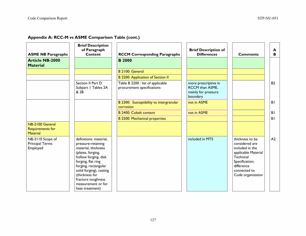
Code Comparison Report STP-NU-051
127
Appendix A: RCC-M vs ASME Comparison Table (cont.)
ASME NB Paragraphs
Brief Description of Paragraph
Content
RCCM Corresponding Paragraphs
Brief Description of Differences
Comments
A B
Article NB-2000 Material
B 2000
B 2100: General
B 2200: Application of Section II
Section II Part D Subpart 1 Tables 2A & 2B
Table B 2200 : list of applicable procurement specifications
more prescriptive in RCCM than ASME, mainly for pressure boundary
B2
B 2300: Susceptibility to intergranular corrosion
not in ASME B1
B 2400: Cobalt content not in ASME B1
B 2500: Mechanical properties B1
NB-2100 General Requirements for Material
NB-2110 Scope of Principal Terms Employed
definitions: material, pressure-retaining material, thickness (plates, forging, hollow forging, disk forging, flat ring forging, rectangular solid forging), casting (thickness for fracture toughness measurement or for heat treatment)
included in MTS thickness to be considered are included in the applicable Material Technical Specification; difference connected to Code organization
A2
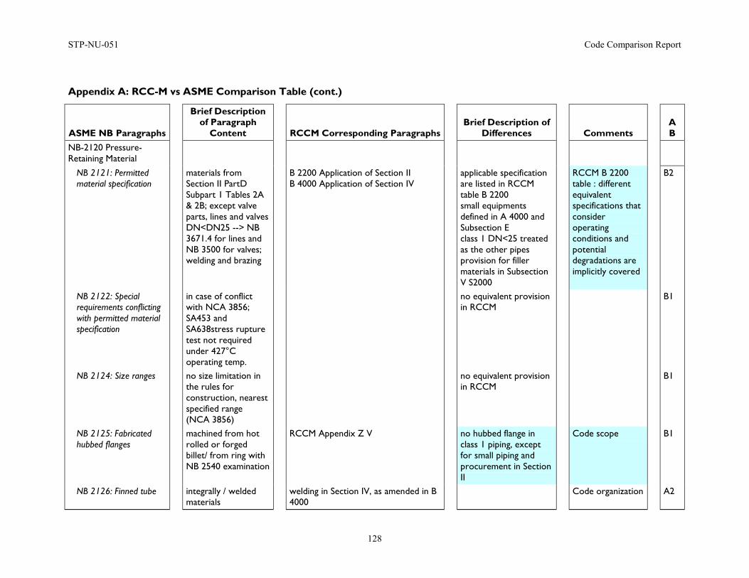
STP-NU-051 Code Comparison Report
128
Appendix A: RCC-M vs ASME Comparison Table (cont.)
ASME NB Paragraphs
Brief Description of Paragraph
Content
RCCM Corresponding Paragraphs
Brief Description of Differences
Comments
A B
NB-2120 Pressure-Retaining Material
NB 2121: Permitted material specification
materials from Section II PartD Subpart 1 Tables 2A & 2B; except valve parts, lines and valves DN<DN25 --> NB 3671.4 for lines and NB 3500 for valves; welding and brazing
B 2200 Application of Section II B 4000 Application of Section IV
applicable specification are listed in RCCM table B 2200 small equipments defined in A 4000 and Subsection E class 1 DN<25 treated as the other pipes provision for filler materials in Subsection V S2000
RCCM B 2200 table : different equivalent specifications that consider operating conditions and potential degradations are implicitly covered
B2
NB 2122: Special requirements conflicting with permitted material specification
in case of conflict with NCA 3856; SA453 and SA638stress rupture test not required under 427°C operating temp.
no equivalent provision in RCCM
B1
NB 2124: Size ranges no size limitation in the rules for construction, nearest specified range (NCA 3856)
no equivalent provision in RCCM
B1
NB 2125: Fabricated hubbed flanges
machined from hot rolled or forged billet/ from ring with NB 2540 examination
RCCM Appendix Z V no hubbed flange in class 1 piping, except for small piping and procurement in Section II
Code scope B1
NB 2126: Finned tube integrally / welded materials
welding in Section IV, as amended in B 4000
Code organization A2
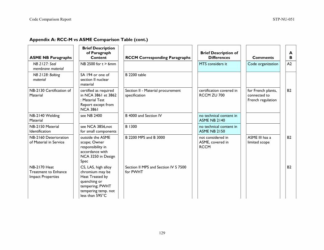
Code Comparison Report STP-NU-051
129
Appendix A: RCC-M vs ASME Comparison Table (cont.)
ASME NB Paragraphs
Brief Description of Paragraph
Content
RCCM Corresponding Paragraphs
Brief Description of Differences
Comments
A B
NB 2127: Seal membrane material
NB 2500 for t > 6mm MTS considers it Code organization A2
NB 2128: Bolting material
SA 194 or one of section II nuclear material
B 2200 table
NB-2130 Certification of Material
certified as required in NCA 3861 et 3862 : Material Test Report except from NCA 3861
Section II - Material procurement specification
certification covered in RCCM ZU 700
for French plants, connected to French regulation
B2
NB-2140 Welding Material
see NB 2400 B 4000 and Section IV no technical content in ASME NB 2140
NB-2150 Material Identification
see NCA 3856,not for small components
B 1300 no technical content in ASME NB 2150
NB-2160 Deterioration of Material in Service
outside the ASME scope; Owner responsibility in accordance with NCA 3250 in Design Spec
B 2200 MPS and B 3000 not considered in ASME, covered in RCCM
ASME III has a limited scope
B2
NB-2170 Heat Treatment to Enhance Impact Properties
CS, LAS, high alloy chromium may be Heat Treated by quenching or tempering; PWHT tempering temp. not less than 595°C
Section II MPS and Section IV S 7500 for PWHT
B2
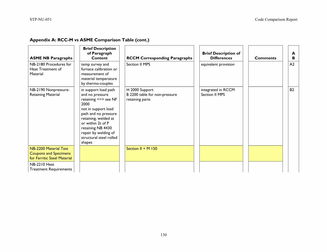
STP-NU-051 Code Comparison Report
130
Appendix A: RCC-M vs ASME Comparison Table (cont.)
ASME NB Paragraphs
Brief Description of Paragraph
Content
RCCM Corresponding Paragraphs
Brief Description of Differences
Comments
A B
NB-2180 Procedures for Heat Treatment of Material
temp survey and furnace calibration or measurement of material temperature by thermo-couples
Section II MPS equivalent provision A2
NB-2190 Nonpressure-Retaining Material
in support load path and no pressure retaining ==> see NF 2000 not in support load path and no pressure retaining, welded at or within 2t of P retaining NB 4430 repair by welding of structural steel rolled shapes
H 2000 Support B 2200 table for non-pressure retaining parts
integrated in RCCM Section II MPS
B2
NB-2200 Material Test Coupons and Specimens for Ferritic Steel Material
Section II + M 150
NB-2210 Heat Treatment Requirements
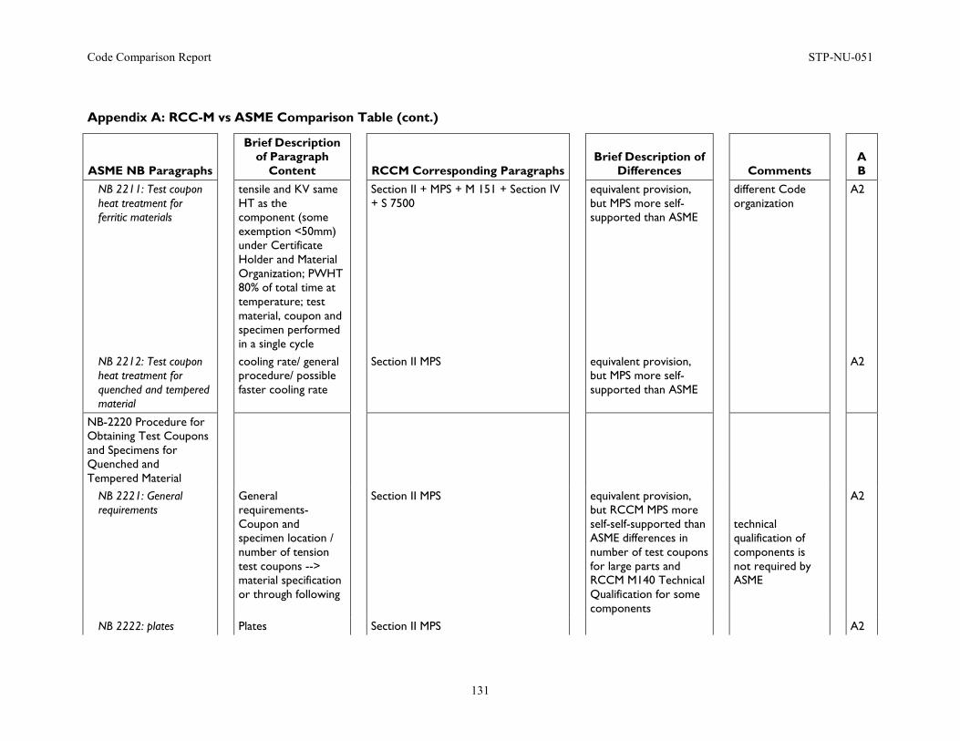
Code Comparison Report STP-NU-051
131
Appendix A: RCC-M vs ASME Comparison Table (cont.)
ASME NB Paragraphs
Brief Description of Paragraph
Content
RCCM Corresponding Paragraphs
Brief Description of Differences
Comments
A B
NB 2211: Test coupon heat treatment for ferritic materials
tensile and KV same HT as the component (some exemption <50mm) under Certificate Holder and Material Organization; PWHT 80% of total time at temperature; test material, coupon and specimen performed in a single cycle
Section II + MPS + M 151 + Section IV + S 7500
equivalent provision, but MPS more self-supported than ASME
different Code organization
A2
NB 2212: Test coupon heat treatment for quenched and tempered material
cooling rate/ general procedure/ possible faster cooling rate
Section II MPS equivalent provision, but MPS more self-supported than ASME
A2
NB-2220 Procedure for Obtaining Test Coupons and Specimens for Quenched and Tempered Material
NB 2221: General requirements
General requirements- Coupon and specimen location / number of tension test coupons --> material specification or through following
Section II MPS equivalent provision, but RCCM MPS more self-self-supported than ASME differences in number of test coupons for large parts and RCCM M140 Technical Qualification for some components
technical qualification of components is not required by ASME
A2
NB 2222: plates Plates Section II MPS A2
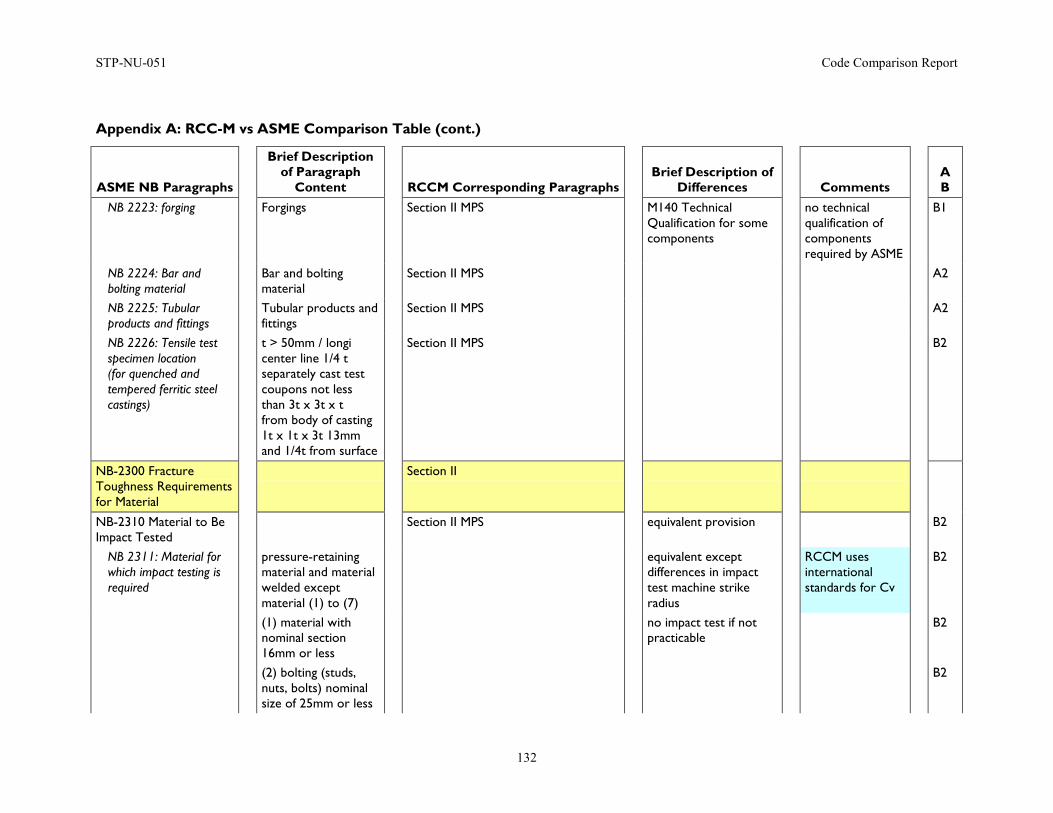
STP-NU-051 Code Comparison Report
132
Appendix A: RCC-M vs ASME Comparison Table (cont.)
ASME NB Paragraphs
Brief Description of Paragraph
Content
RCCM Corresponding Paragraphs
Brief Description of Differences
Comments
A B
NB 2223: forging Forgings Section II MPS M140 Technical Qualification for some components
no technical qualification of components required by ASME
B1
NB 2224: Bar and bolting material
Bar and bolting material
Section II MPS A2
NB 2225: Tubular products and fittings
Tubular products and fittings
Section II MPS A2
NB 2226: Tensile test specimen location (for quenched and tempered ferritic steel castings)
t > 50mm / longi center line 1/4 t separately cast test coupons not less than 3t x 3t x t from body of casting 1t x 1t x 3t 13mm and 1/4t from surface
Section II MPS B2
NB-2300 Fracture Toughness Requirements for Material
Section II
NB-2310 Material to Be Impact Tested
Section II MPS equivalent provision B2
NB 2311: Material for which impact testing is required
pressure-retaining material and material welded except material (1) to (7)
equivalent except differences in impact test machine strike radius
RCCM uses international standards for Cv
B2
(1) material with nominal section 16mm or less
no impact test if not practicable
B2
(2) bolting (studs, nuts, bolts) nominal size of 25mm or less
B2
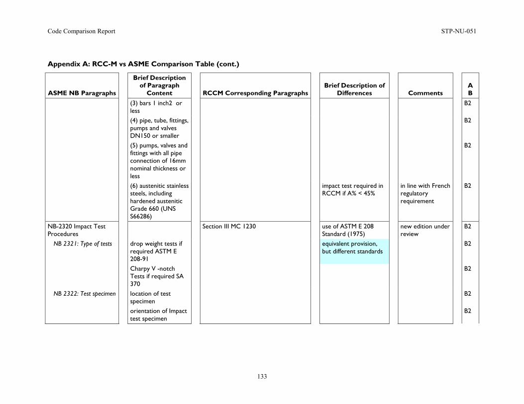
Code Comparison Report STP-NU-051
133
Appendix A: RCC-M vs ASME Comparison Table (cont.)
ASME NB Paragraphs
Brief Description of Paragraph
Content
RCCM Corresponding Paragraphs
Brief Description of Differences
Comments
A B
(3) bars 1 inch2 or less
B2
(4) pipe, tube, fittings, pumps and valves DN150 or smaller
B2
(5) pumps, valves and fittings with all pipe connection of 16mm nominal thickness or less
B2
(6) austenitic stainless steels, including hardened austenitic Grade 660 (UNS S66286)
impact test required in RCCM if A% < 45%
in line with French regulatory requirement
B2
NB-2320 Impact Test Procedures
Section III MC 1230 use of ASTM E 208 Standard (1975)
new edition under review
B2
NB 2321: Type of tests drop weight tests if required ASTM E 208-91
equivalent provision, but different standards
B2
Charpy V -notch Tests if required SA 370
B2
NB 2322: Test specimen location of test specimen
B2
orientation of Impact test specimen
B2
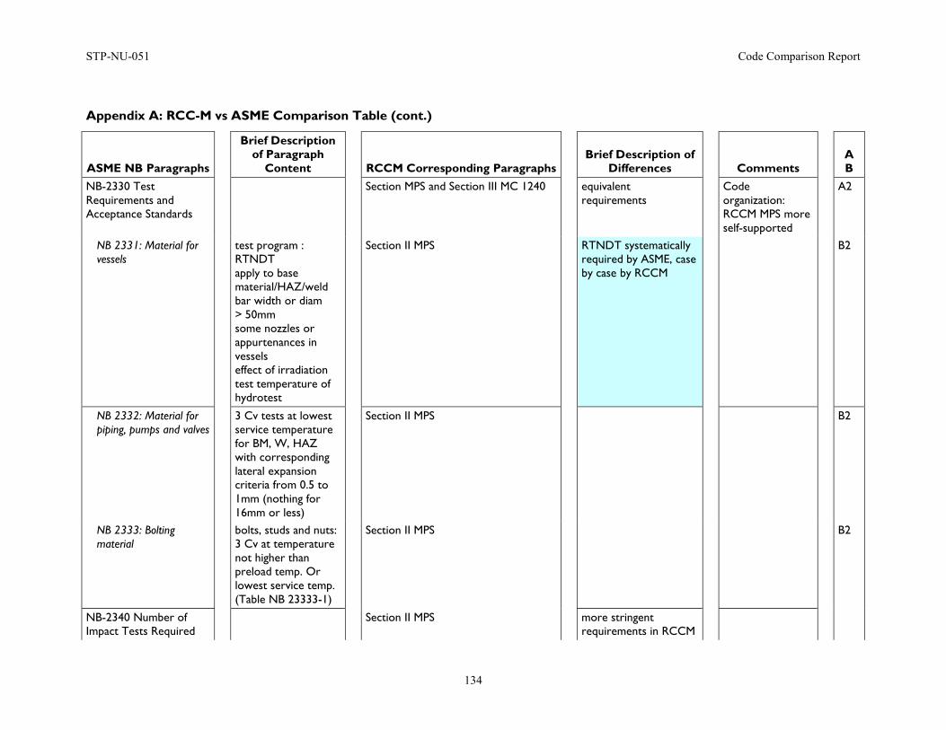
STP-NU-051 Code Comparison Report
134
Appendix A: RCC-M vs ASME Comparison Table (cont.)
ASME NB Paragraphs
Brief Description of Paragraph
Content
RCCM Corresponding Paragraphs
Brief Description of Differences
Comments
A B
NB-2330 Test Requirements and Acceptance Standards
Section MPS and Section III MC 1240 equivalent requirements
Code organization: RCCM MPS more self-supported
A2
NB 2331: Material for vessels
test program : RTNDT apply to base material/HAZ/weld bar width or diam > 50mm some nozzles or appurtenances in vessels effect of irradiation test temperature of hydrotest
Section II MPS RTNDT systematically required by ASME, case by case by RCCM
B2
NB 2332: Material for piping, pumps and valves
3 Cv tests at lowest service temperature for BM, W, HAZ with corresponding lateral expansion criteria from 0.5 to 1mm (nothing for 16mm or less)
Section II MPS B2
NB 2333: Bolting material
bolts, studs and nuts: 3 Cv at temperature not higher than preload temp. Or lowest service temp. (Table NB 23333-1)
Section II MPS B2
NB-2340 Number of Impact Tests Required
Section II MPS more stringent requirements in RCCM
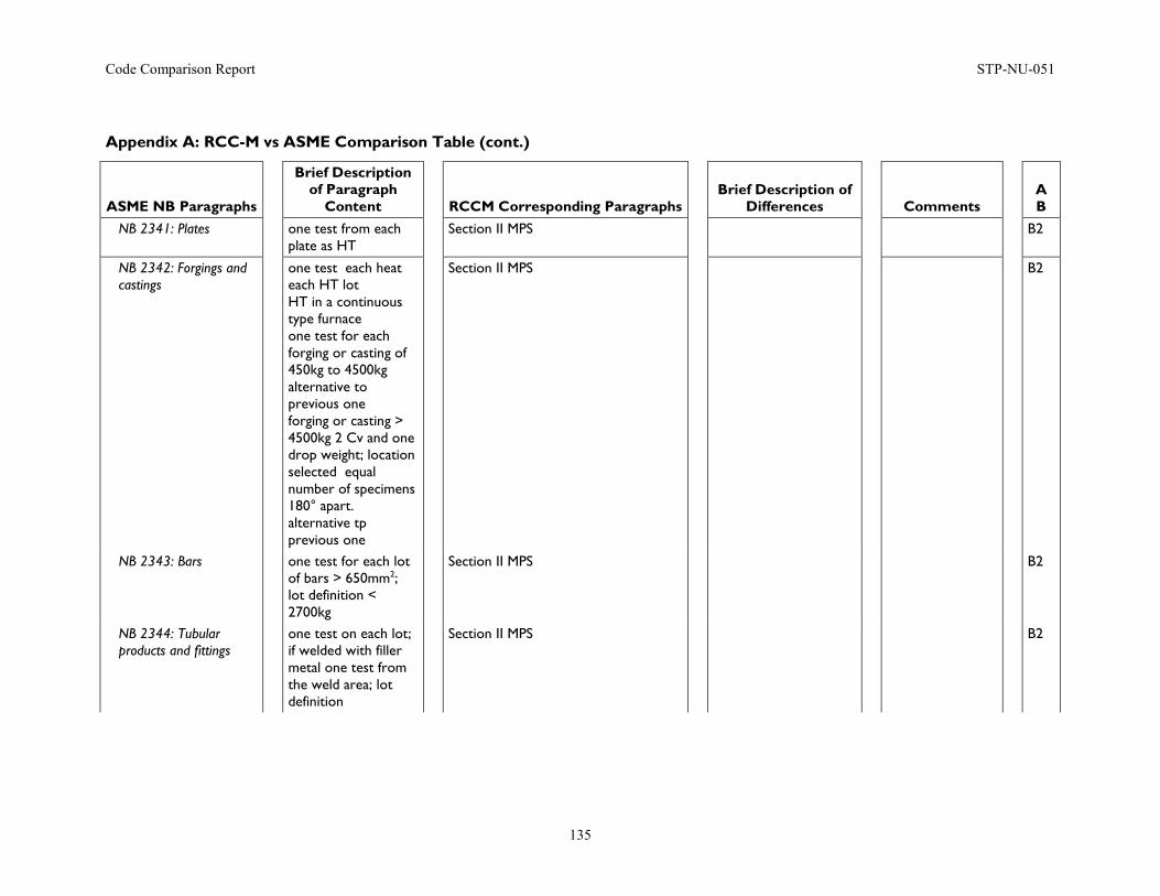
Code Comparison Report STP-NU-051
135
Appendix A: RCC-M vs ASME Comparison Table (cont.)
ASME NB Paragraphs
Brief Description of Paragraph
Content
RCCM Corresponding Paragraphs
Brief Description of Differences
Comments
A B
NB 2341: Plates one test from each plate as HT
Section II MPS B2
NB 2342: Forgings and castings
one test each heat each HT lot HT in a continuous type furnace one test for each forging or casting of 450kg to 4500kg alternative to previous one forging or casting > 4500kg 2 Cv and one drop weight; location selected equal number of specimens 180° apart. alternative tp previous one
Section II MPS B2
NB 2343: Bars one test for each lot of bars > 650mm2; lot definition < 2700kg
Section II MPS B2
NB 2344: Tubular products and fittings
one test on each lot; if welded with filler metal one test from the weld area; lot definition
Section II MPS B2
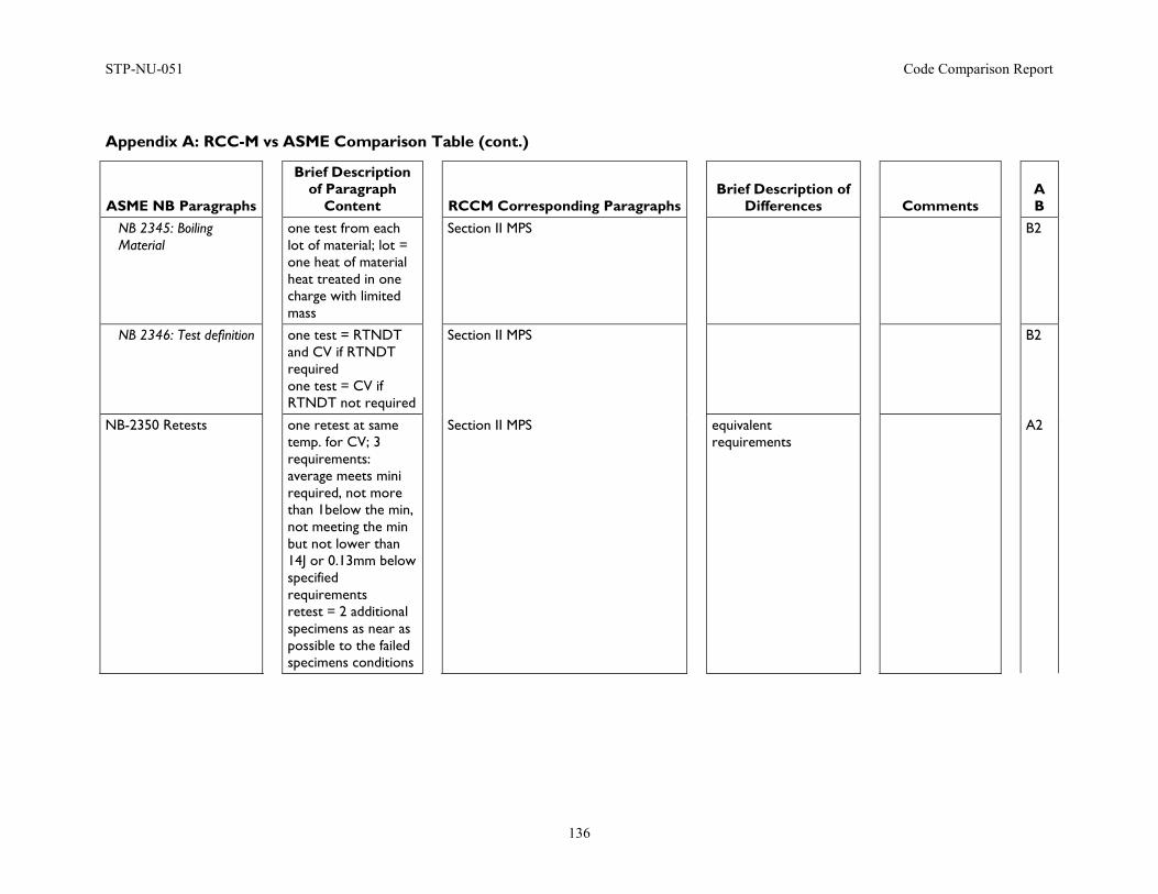
STP-NU-051 Code Comparison Report
136
Appendix A: RCC-M vs ASME Comparison Table (cont.)
ASME NB Paragraphs
Brief Description of Paragraph
Content
RCCM Corresponding Paragraphs
Brief Description of Differences
Comments
A B
NB 2345: Boiling Material
one test from each lot of material; lot = one heat of material heat treated in one charge with limited mass
Section II MPS B2
NB 2346: Test definition one test = RTNDT and CV if RTNDT required one test = CV if RTNDT not required
Section II MPS B2
NB-2350 Retests one retest at same temp. for CV; 3 requirements: average meets mini required, not more than 1below the min, not meeting the min but not lower than 14J or 0.13mm below specified requirements retest = 2 additional specimens as near as possible to the failed specimens conditions
Section II MPS equivalent requirements
A2
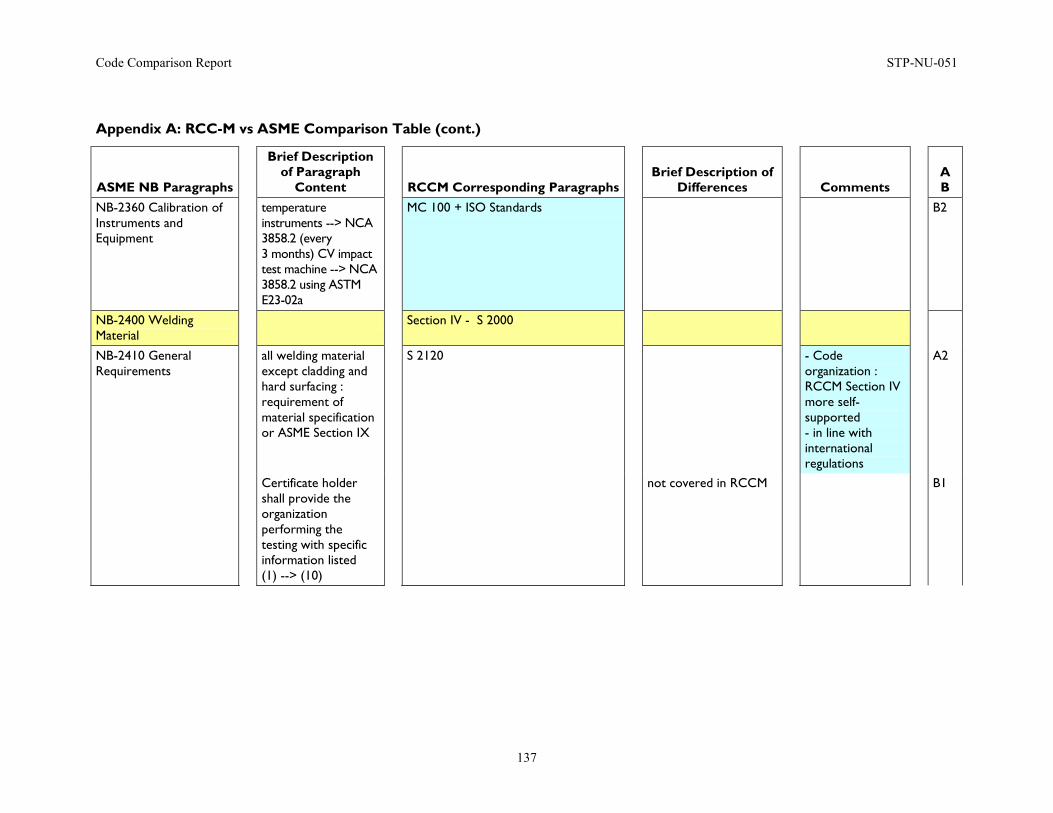
Code Comparison Report STP-NU-051
137
Appendix A: RCC-M vs ASME Comparison Table (cont.)
ASME NB Paragraphs
Brief Description of Paragraph
Content
RCCM Corresponding Paragraphs
Brief Description of Differences
Comments
A B
NB-2360 Calibration of Instruments and Equipment
temperature instruments --> NCA 3858.2 (every 3 months) CV impact test machine --> NCA 3858.2 using ASTM E23-02a
MC 100 + ISO Standards B2
NB-2400 Welding Material
Section IV - S 2000
NB-2410 General Requirements
all welding material except cladding and hard surfacing : requirement of material specification or ASME Section IX
S 2120 - Code organization : RCCM Section IV more self-supported - in line with international regulations
A2
Certificate holder shall provide the organization performing the testing with specific information listed (1) --> (10)
not covered in RCCM B1
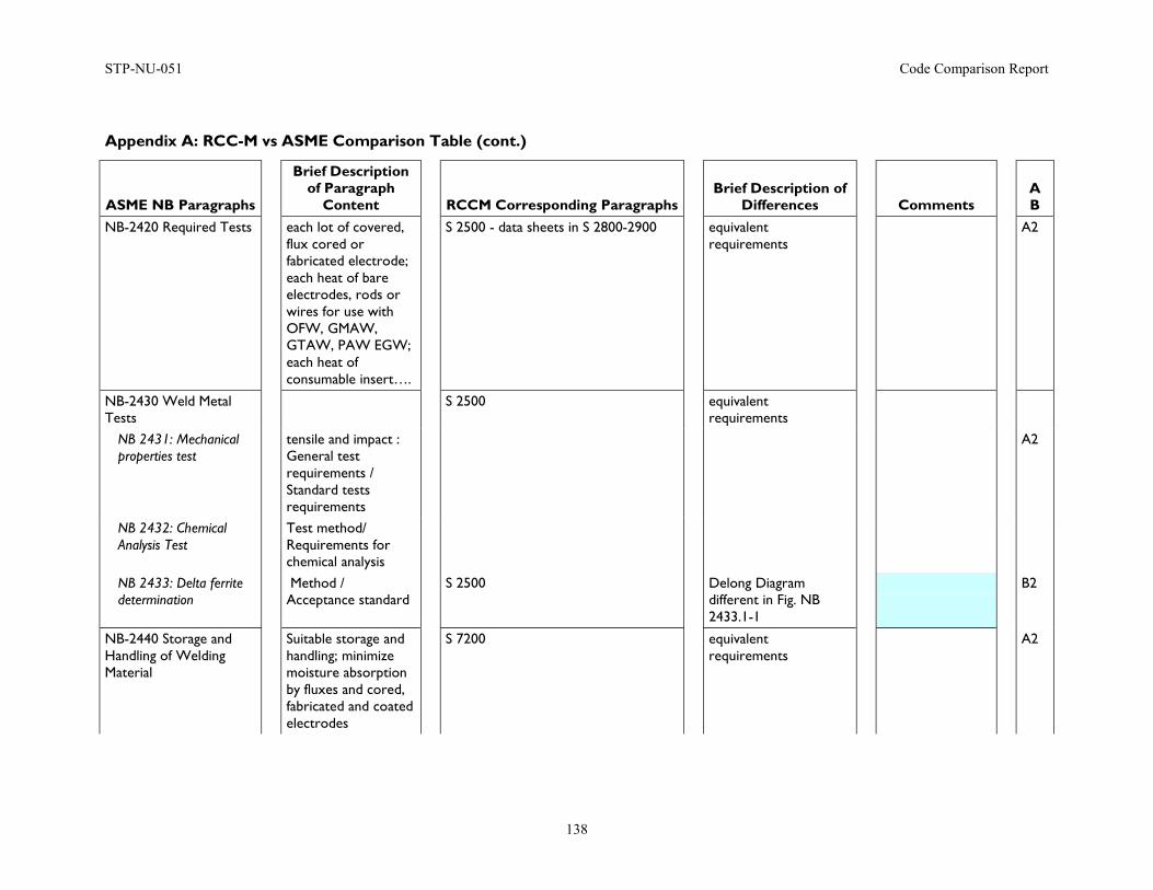
STP-NU-051 Code Comparison Report
138
Appendix A: RCC-M vs ASME Comparison Table (cont.)
ASME NB Paragraphs
Brief Description of Paragraph
Content
RCCM Corresponding Paragraphs
Brief Description of Differences
Comments
A B
NB-2420 Required Tests each lot of covered, flux cored or fabricated electrode; each heat of bare electrodes, rods or wires for use with OFW, GMAW, GTAW, PAW EGW; each heat of consumable insert….
S 2500 - data sheets in S 2800-2900 equivalent requirements
A2
NB-2430 Weld Metal Tests
S 2500 equivalent requirements
NB 2431: Mechanical properties test
tensile and impact : General test requirements / Standard tests requirements
A2
NB 2432: Chemical Analysis Test
Test method/ Requirements for chemical analysis
NB 2433: Delta ferrite determination
Method / Acceptance standard
S 2500 Delong Diagram different in Fig. NB 2433.1-1
B2
NB-2440 Storage and Handling of Welding Material
Suitable storage and handling; minimize moisture absorption by fluxes and cored, fabricated and coated electrodes
S 7200 equivalent requirements
A2
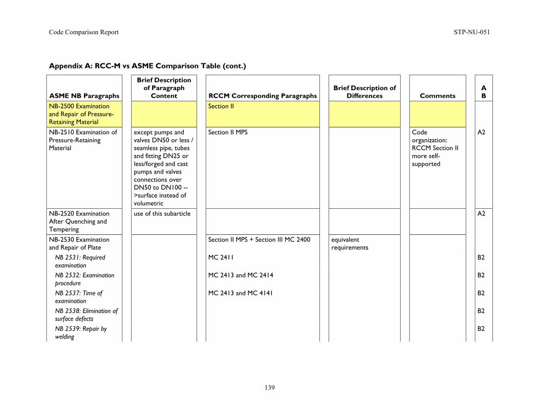
Code Comparison Report STP-NU-051
139
Appendix A: RCC-M vs ASME Comparison Table (cont.)
ASME NB Paragraphs
Brief Description of Paragraph
Content
RCCM Corresponding Paragraphs
Brief Description of Differences
Comments
A B
NB-2500 Examination and Repair of Pressure-Retaining Material
Section II
NB-2510 Examination of Pressure-Retaining Material
except pumps and valves DN50 or less / seamless pipe, tubes and fitting DN25 or less/forged and cast pumps and valves connections over DN50 to DN100 -->surface instead of volumetric
Section II MPS Code organization: RCCM Section II more self-supported
A2
NB-2520 Examination After Quenching and Tempering
use of this subarticle A2
NB-2530 Examination and Repair of Plate
Section II MPS + Section III MC 2400 equivalent requirements
NB 2531: Required examination
MC 2411 B2
NB 2532: Examination procedure
MC 2413 and MC 2414 B2
NB 2537: Time of examination
MC 2413 and MC 4141 B2
NB 2538: Elimination of surface defects
B2
NB 2539: Repair by welding
B2
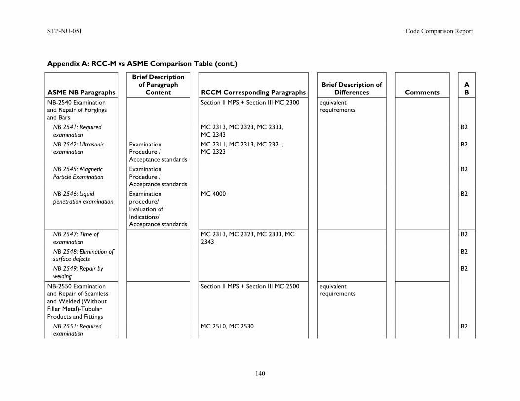
STP-NU-051 Code Comparison Report
140
Appendix A: RCC-M vs ASME Comparison Table (cont.)
ASME NB Paragraphs
Brief Description of Paragraph
Content
RCCM Corresponding Paragraphs
Brief Description of Differences
Comments
A B
NB-2540 Examination and Repair of Forgings and Bars
Section II MPS + Section III MC 2300 equivalent requirements
NB 2541: Required examination
MC 2313, MC 2323, MC 2333, MC 2343
B2
NB 2542: Ultrasonic examination
Examination Procedure / Acceptance standards
MC 2311, MC 2313, MC 2321, MC 2323
B2
NB 2545: Magnetic Particle Examination
Examination Procedure / Acceptance standards
B2
NB 2546: Liquid penetration examination
Examination procedure/ Evaluation of Indications/ Acceptance standards
MC 4000 B2
NB 2547: Time of examination
MC 2313, MC 2323, MC 2333, MC 2343
B2
NB 2548: Elimination of surface defects
B2
NB 2549: Repair by welding
B2
NB-2550 Examination and Repair of Seamless and Welded (Without Filler Metal)-Tubular Products and Fittings
Section II MPS + Section III MC 2500 equivalent requirements
NB 2551: Required examination
MC 2510, MC 2530 B2
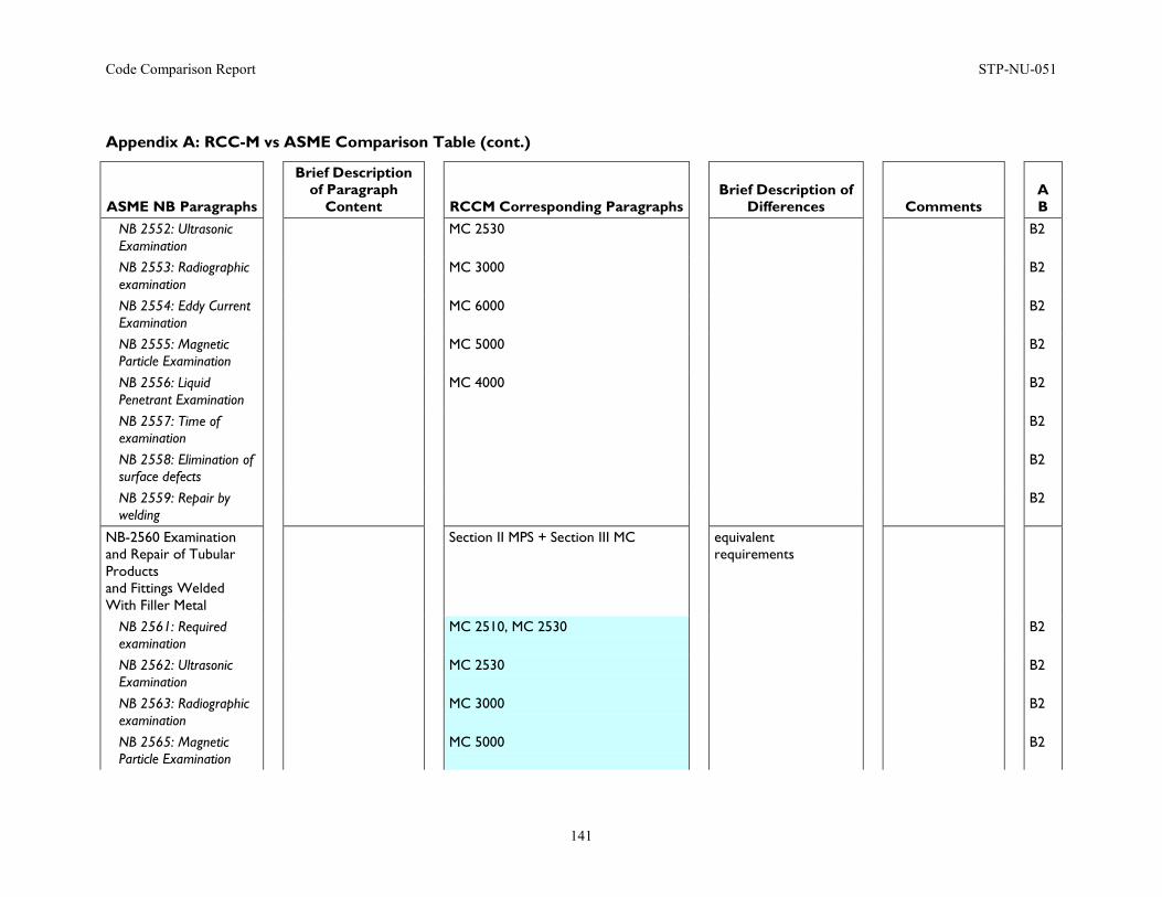
Code Comparison Report STP-NU-051
141
Appendix A: RCC-M vs ASME Comparison Table (cont.)
ASME NB Paragraphs
Brief Description of Paragraph
Content
RCCM Corresponding Paragraphs
Brief Description of Differences
Comments
A B
NB 2552: Ultrasonic Examination
MC 2530 B2
NB 2553: Radiographic examination
MC 3000 B2
NB 2554: Eddy Current Examination
MC 6000 B2
NB 2555: Magnetic Particle Examination
MC 5000 B2
NB 2556: Liquid Penetrant Examination
MC 4000 B2
NB 2557: Time of examination
B2
NB 2558: Elimination of surface defects
B2
NB 2559: Repair by welding
B2
NB-2560 Examination and Repair of Tubular Products and Fittings Welded With Filler Metal
Section II MPS + Section III MC equivalent requirements
NB 2561: Required examination
MC 2510, MC 2530 B2
NB 2562: Ultrasonic Examination
MC 2530 B2
NB 2563: Radiographic examination
MC 3000 B2
NB 2565: Magnetic Particle Examination
MC 5000 B2
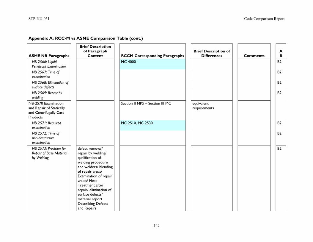
STP-NU-051 Code Comparison Report
142
Appendix A: RCC-M vs ASME Comparison Table (cont.)
ASME NB Paragraphs
Brief Description of Paragraph
Content
RCCM Corresponding Paragraphs
Brief Description of Differences
Comments
A B
NB 2566: Liquid Penetrant Examination
MC 4000 B2
NB 2567: Time of examination
B2
NB 2568: Elimination of surface defects
B2
NB 2569: Repair by welding
B2
NB-2570 Examination and Repair of Statically and Centrifugally Cast Products
Section II MPS + Section III MC equivalent requirements
NB 2571: Required examination
MC 2510, MC 2530 B2
NB 2572: Time of non-destructive examination
B2
NB 2573: Provision for Repair of Base Material by Welding
defect removal/ repair by welding/ qualification of welding procedure and welders/ blending of repair areas/ Examination of repair welds/ Heat Treatment after repair/ elimination of surface defects/ material report Describing Defects and Repairs
B2
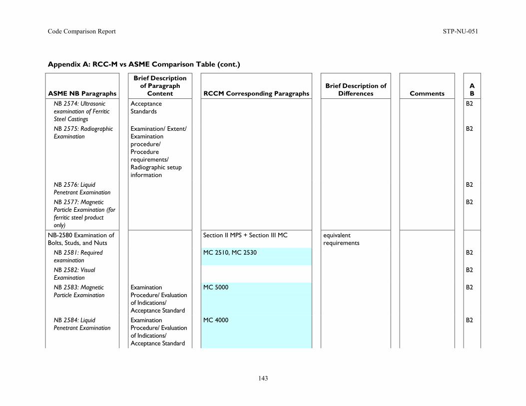
Code Comparison Report STP-NU-051
143
Appendix A: RCC-M vs ASME Comparison Table (cont.)
ASME NB Paragraphs
Brief Description of Paragraph
Content
RCCM Corresponding Paragraphs
Brief Description of Differences
Comments
A B
NB 2574: Ultrasonic examination of Ferritic Steel Castings
Acceptance Standards
B2
NB 2575: Radiographic Examination
Examination/ Extent/ Examination procedure/ Procedure requirements/ Radiographic setup information
B2
NB 2576: Liquid Penetrant Examination
B2
NB 2577: Magnetic Particle Examination (for ferritic steel product only)
B2
NB-2580 Examination of Bolts, Studs, and Nuts
Section II MPS + Section III MC equivalent requirements
NB 2581: Required examination
MC 2510, MC 2530 B2
NB 2582: Visual Examination
B2
NB 2583: Magnetic Particle Examination
Examination Procedure/ Evaluation of Indications/ Acceptance Standard
MC 5000 B2
NB 2584: Liquid Penetrant Examination
Examination Procedure/ Evaluation of Indications/ Acceptance Standard
MC 4000 B2
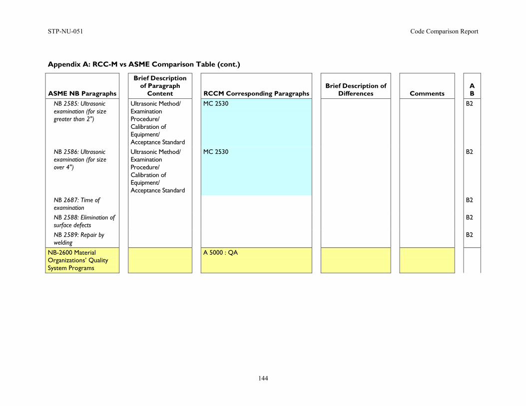
STP-NU-051 Code Comparison Report
144
Appendix A: RCC-M vs ASME Comparison Table (cont.)
ASME NB Paragraphs
Brief Description of Paragraph
Content
RCCM Corresponding Paragraphs
Brief Description of Differences
Comments
A B
NB 2585: Ultrasonic examination (for size greater than 2")
Ultrasonic Method/ Examination Procedure/ Calibration of Equipment/ Acceptance Standard
MC 2530 B2
NB 2586: Ultrasonic examination (for size over 4")
Ultrasonic Method/ Examination Procedure/ Calibration of Equipment/ Acceptance Standard
MC 2530 B2
NB 2687: Time of examination
B2
NB 2588: Elimination of surface defects
B2
NB 2589: Repair by welding
B2
NB-2600 Material Organizations’ Quality System Programs
A 5000 : QA
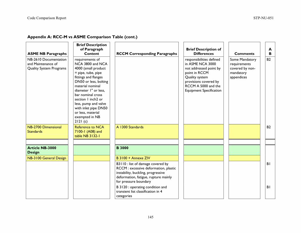
Code Comparison Report STP-NU-051
145
Appendix A: RCC-M vs ASME Comparison Table (cont.)
ASME NB Paragraphs
Brief Description of Paragraph
Content
RCCM Corresponding Paragraphs
Brief Description of Differences
Comments
A B
NB-2610 Documentation and Maintenance of Quality System Programs
requirements of NCA 3800 and NCA 4000 (small product = pipe, tube, pipe fittings and flanges DN50 or less, bolting material nominal diameter 1" or less, bar nominal cross section 1 inch2 or less, pump and valve with inlet pipe DN50 or less, material exempted in NB 2121 (c)
responsibilities defined in ASME NCA 3000 not addressed point by point in RCCM Quality system provisions covered by RCCM A 5000 and the Equipment Specification
Some Mandatory requirements covered by non-mandatory appendices
B2
NB-2700 Dimensional Standards
Reference to NCA 7100-1 (A08) and table NB 3132-1
A 1300 Standards B2
Article NB-3000 Design
B 3000
NB-3100 General Design B 3100 + Annexe ZIV
B3110 : list of damage covered by RCCM : excessive deformation, plastic instability, buckling, progressive deformation, fatigue, rupture mainly for pressure boundary
B1
B 3120 : operating condition and transient list classification in 4 categories
B1
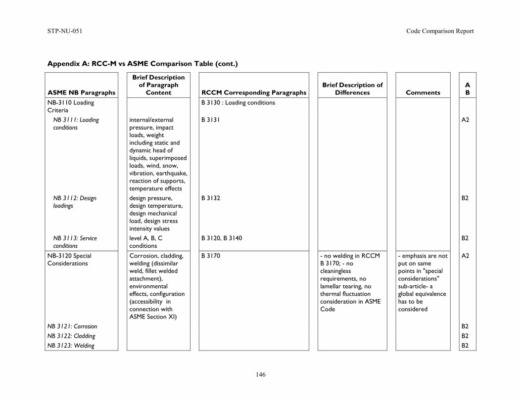
STP-NU-051 Code Comparison Report
146
Appendix A: RCC-M vs ASME Comparison Table (cont.)
ASME NB Paragraphs
Brief Description of Paragraph
Content
RCCM Corresponding Paragraphs
Brief Description of Differences
Comments
A B
NB-3110 Loading Criteria
B 3130 : Loading conditions
NB 3111: Loading conditions
internal/external pressure, impact loads, weight including static and dynamic head of liquids, superimposed loads, wind, snow, vibration, earthquake, reaction of supports, temperature effects
B 3131 A2
NB 3112: Design loadings
design pressure, design temperature, design mechanical load, design stress intensity values
B 3132 B2
NB 3113: Service conditions
level A, B, C conditions
B 3120, B 3140 B2
NB-3120 Special Considerations
Corrosion, cladding, welding (dissimilar weld, fillet welded attachment), environmental effects, configuration (accessibility in connection with ASME Section XI)
B 3170 - no welding in RCCM B 3170; - no cleaningless requirements, no lamellar tearing, no thermal fluctuation consideration in ASME Code
- emphasis are not put on same points in "special considerations" sub-article- a global equivalence has to be considered
A2
NB 3121: Corrosion B2 NB 3122: Cladding B2 NB 3123: Welding B2
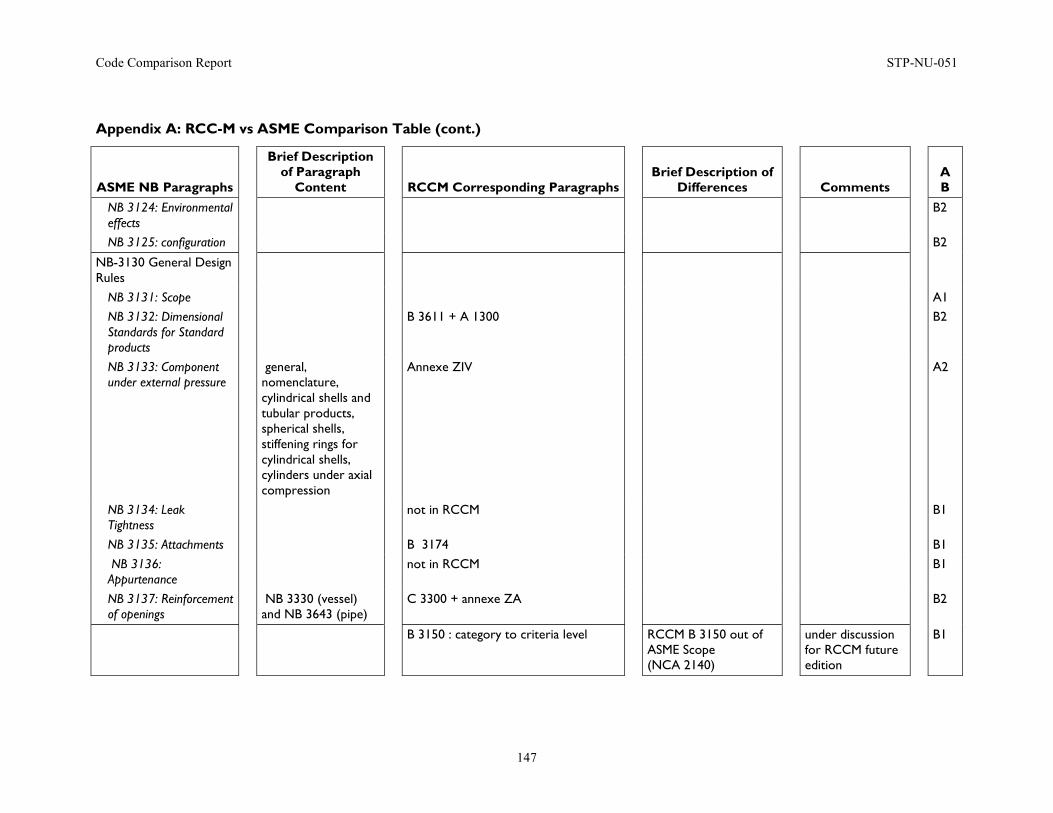
Code Comparison Report STP-NU-051
147
Appendix A: RCC-M vs ASME Comparison Table (cont.)
ASME NB Paragraphs
Brief Description of Paragraph
Content
RCCM Corresponding Paragraphs
Brief Description of Differences
Comments
A B
NB 3124: Environmental effects
B2
NB 3125: configuration B2
NB-3130 General Design Rules
NB 3131: Scope A1 NB 3132: Dimensional Standards for Standard products
B 3611 + A 1300 B2
NB 3133: Component under external pressure
general, nomenclature, cylindrical shells and tubular products, spherical shells, stiffening rings for cylindrical shells, cylinders under axial compression
Annexe ZIV A2
NB 3134: Leak Tightness
not in RCCM B1
NB 3135: Attachments B 3174 B1 NB 3136: Appurtenance
not in RCCM B1
NB 3137: Reinforcement of openings
NB 3330 (vessel) and NB 3643 (pipe)
C 3300 + annexe ZA B2
B 3150 : category to criteria level RCCM B 3150 out of ASME Scope (NCA 2140)
under discussion for RCCM future edition
B1
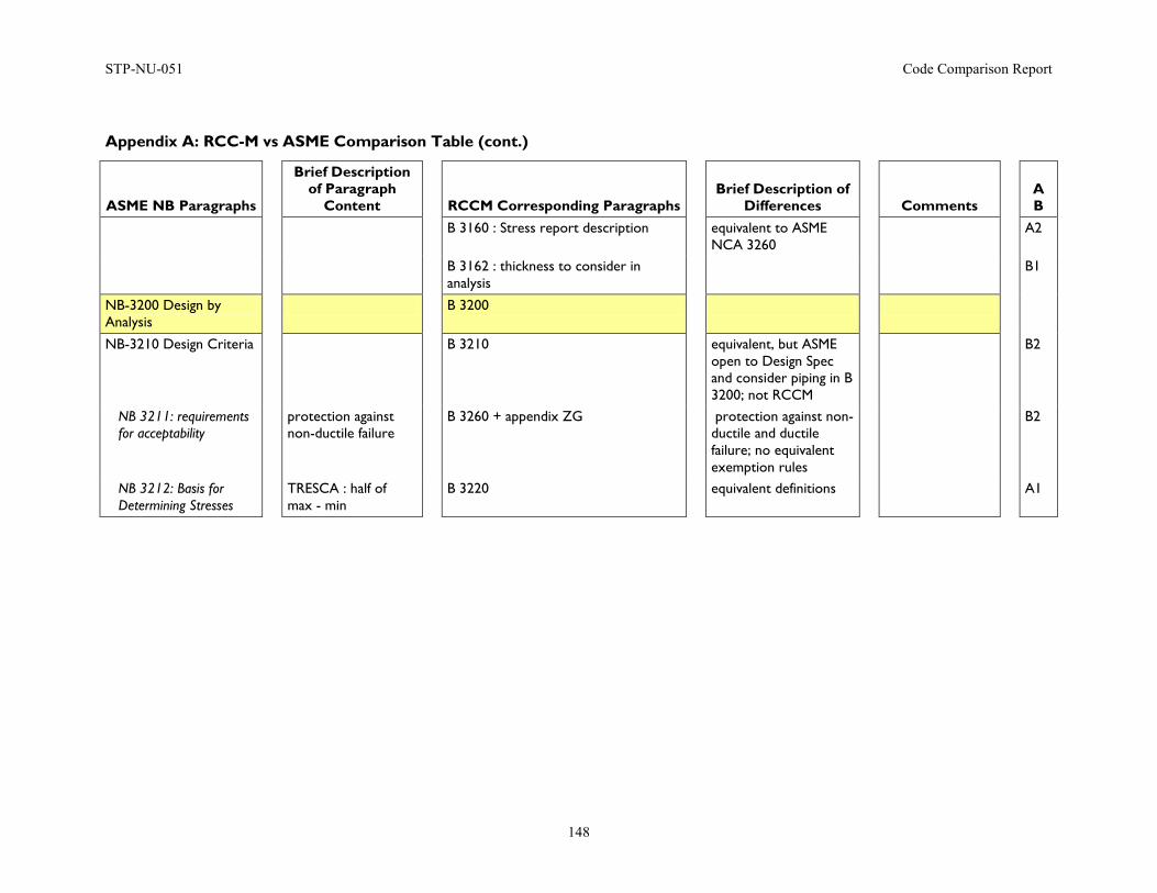
STP-NU-051 Code Comparison Report
148
Appendix A: RCC-M vs ASME Comparison Table (cont.)
ASME NB Paragraphs
Brief Description of Paragraph
Content
RCCM Corresponding Paragraphs
Brief Description of Differences
Comments
A B
B 3160 : Stress report description equivalent to ASME NCA 3260
A2
B 3162 : thickness to consider in analysis
B1
NB-3200 Design by Analysis
B 3200
NB-3210 Design Criteria B 3210 equivalent, but ASME open to Design Spec and consider piping in B 3200; not RCCM
B2
NB 3211: requirements for acceptability
protection against non-ductile failure
B 3260 + appendix ZG protection against non-ductile and ductile failure; no equivalent exemption rules
B2
NB 3212: Basis for Determining Stresses
TRESCA : half of max - min
B 3220 equivalent definitions A1
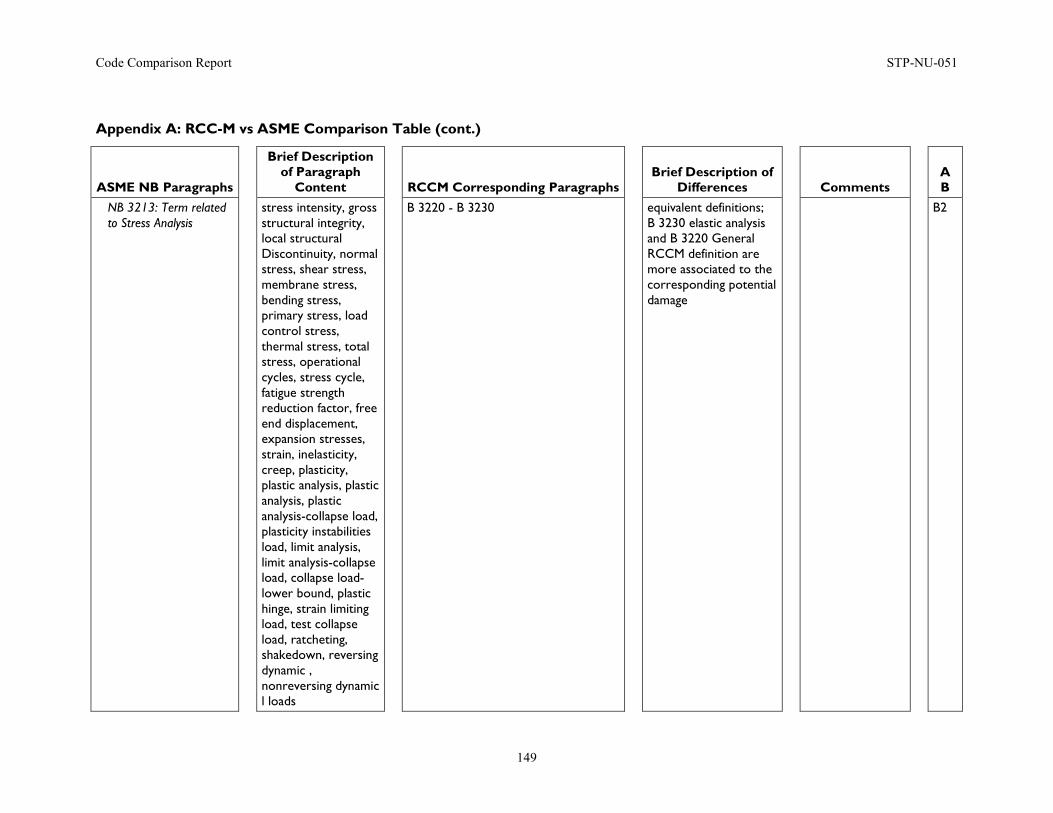
Code Comparison Report STP-NU-051
149
Appendix A: RCC-M vs ASME Comparison Table (cont.)
ASME NB Paragraphs
Brief Description of Paragraph
Content
RCCM Corresponding Paragraphs
Brief Description of Differences
Comments
A B
NB 3213: Term related to Stress Analysis
stress intensity, gross structural integrity, local structural Discontinuity, normal stress, shear stress, membrane stress, bending stress, primary stress, load control stress, thermal stress, total stress, operational cycles, stress cycle, fatigue strength reduction factor, free end displacement, expansion stresses, strain, inelasticity, creep, plasticity, plastic analysis, plastic analysis, plastic analysis-collapse load, plasticity instabilities load, limit analysis, limit analysis-collapse load, collapse load-lower bound, plastic hinge, strain limiting load, test collapse load, ratcheting, shakedown, reversing dynamic , nonreversing dynamic l loads
B 3220 - B 3230 equivalent definitions; B 3230 elastic analysis and B 3220 General RCCM definition are more associated to the corresponding potential damage
B2
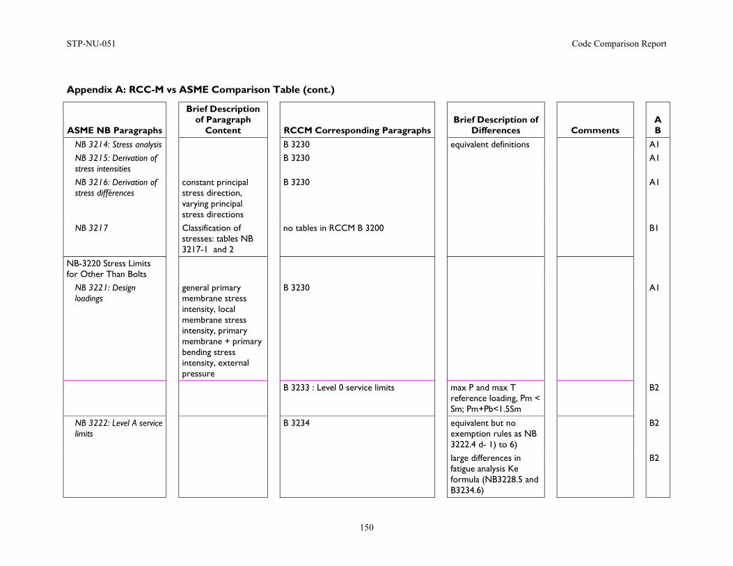
STP-NU-051 Code Comparison Report
150
Appendix A: RCC-M vs ASME Comparison Table (cont.)
ASME NB Paragraphs
Brief Description of Paragraph
Content
RCCM Corresponding Paragraphs
Brief Description of Differences
Comments
A B
NB 3214: Stress analysis B 3230 equivalent definitions A1 NB 3215: Derivation of stress intensities
B 3230 A1
NB 3216: Derivation of stress différences
constant principal stress direction, varying principal stress directions
B 3230 A1
NB 3217 Classification of stresses: tables NB 3217-1 and 2
no tables in RCCM B 3200 B1
NB-3220 Stress Limits for Other Than Bolts
NB 3221: Design loadings
general primary membrane stress intensity, local membrane stress intensity, primary membrane + primary bending stress intensity, external pressure
B 3230 A1
B 3233 : Level 0 service limits max P and max T reference loading, Pm < Sm; Pm+Pb<1.5Sm
B2
NB 3222: Level A service limits
B 3234 equivalent but no exemption rules as NB 3222.4 d- 1) to 6)
B2
large differences in fatigue analysis Ke formula (NB3228.5 and B3234.6)
B2
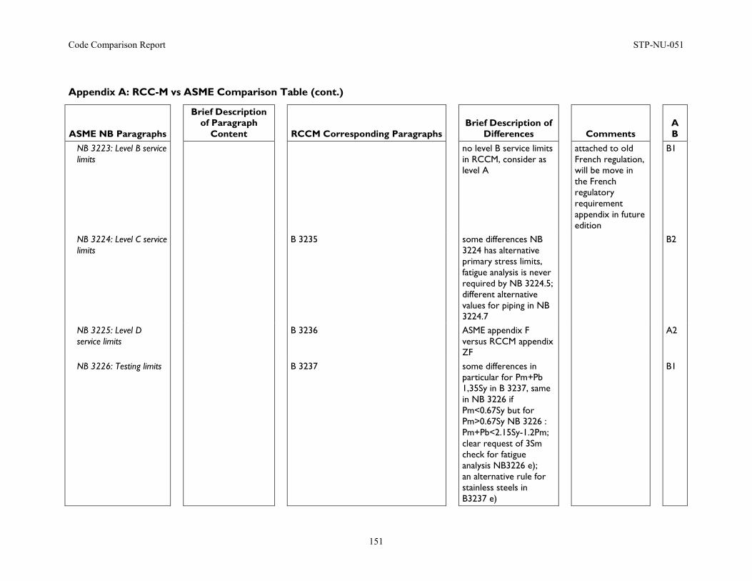
Code Comparison Report STP-NU-051
151
Appendix A: RCC-M vs ASME Comparison Table (cont.)
ASME NB Paragraphs
Brief Description of Paragraph
Content
RCCM Corresponding Paragraphs
Brief Description of Differences
Comments
A B
NB 3223: Level B service limits
no level B service limits in RCCM, consider as level A
attached to old French regulation, will be move in the French regulatory requirement appendix in future edition
B1
NB 3224: Level C service limits
B 3235 some differences NB 3224 has alternative primary stress limits, fatigue analysis is never required by NB 3224.5; different alternative values for piping in NB 3224.7
B2
NB 3225: Level D service limits
B 3236 ASME appendix F versus RCCM appendix ZF
A2
NB 3226: Testing limits B 3237 some differences in particular for Pm+Pb 1,35Sy in B 3237, same in NB 3226 if Pm<0.67Sy but for Pm>0.67Sy NB 3226 : Pm+Pb<2.15Sy-1.2Pm; clear request of 3Sm check for fatigue analysis NB3226 e); an alternative rule for stainless steels in B3237 e)
B1
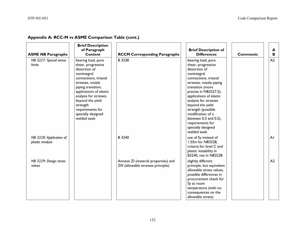
STP-NU-051 Code Comparison Report
152
Appendix A: RCC-M vs ASME Comparison Table (cont.)
ASME NB Paragraphs
Brief Description of Paragraph
Content
RCCM Corresponding Paragraphs
Brief Description of Differences
Comments
A B
NB 3227: Special stress limits
bearing load, pure shear, progressive distortion of nonintegral connections, triaxial stresses, nozzle piping transition, applications of elastic analysis for stresses beyond the yield strength requirements for specially designed welded seals
B 3238 bearing load, pure shear, progressive distortion of nonintegral connections, triaxial stresses, nozzle piping transition (more precise in NB3227.5), applications of elastic analysis for stresses beyond the yield strength (possible modification of n between 0.3 and 0.5), requirements for specially designed welded seals
A2
NB 3228: Application of plastic analysis
B 3240 use of Sy instead of 1.5Sm for NB3228, criteria for level C and plastic instability in B3240, not in NB3228
A1
NB 3229: Design stress values
Annexe ZI (material properties) and ZIII (allowable stresses principle)
slightly different principle, but equivalent allowable stress values; possible differences in procurement check for Sy at room temperature (with no consequences on the allowable stress)
A2
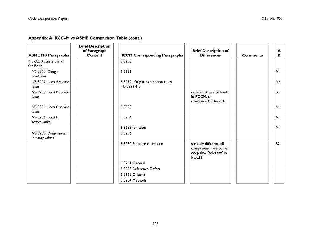
Code Comparison Report STP-NU-051
153
Appendix A: RCC-M vs ASME Comparison Table (cont.)
ASME NB Paragraphs
Brief Description of Paragraph
Content
RCCM Corresponding Paragraphs
Brief Description of Differences
Comments
A B
NB-3230 Stress Limits for Bolts
B 3250
NB 3231: Design conditions
B 3251 A1
NB 3232: Level A service limits
B 3252 : fatigue exemption rules NB 3222.4 d,
A2
NB 3233: Level B service limits
no level B service limits in RCCM, all considered as level A
B2
NB 3234: Level C service limits
B 3253 A1
NB 3235: Level D service limits
B 3254 A1
B 3255 for tests A1 NB 3236: Design stress intensity values
B 3256
B 3260 Fracture resistance strongly different, all component have to be deep flaw "tolerant" in RCCM
B2
B 3261 General B 3262 Reference Defect B 3263 Criteria B 3264 Methods
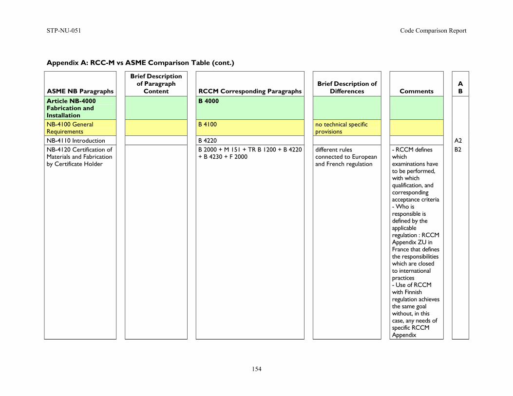
STP-NU-051 Code Comparison Report
154
Appendix A: RCC-M vs ASME Comparison Table (cont.)
ASME NB Paragraphs
Brief Description of Paragraph
Content
RCCM Corresponding Paragraphs
Brief Description of Differences
Comments
A B
Article NB-4000 Fabrication and Installation
B 4000
NB-4100 General Requirements
B 4100 no technical specific provisions
NB-4110 Introduction B 4220 A2 NB-4120 Certification of Materials and Fabrication by Certificate Holder
B 2000 + M 151 + TR B 1200 + B 4220 + B 4230 + F 2000
different rules connected to European and French regulation
- RCCM defines which examinations have to be performed, with which qualification, and corresponding acceptance criteria - Who is responsible is defined by the applicable regulation : RCCM Appendix ZU in France that defines the responsibilities which are closed to international practices - Use of RCCM with Finnish regulation achieves the same goal without, in this case, any needs of specific RCCM Appendix
B2
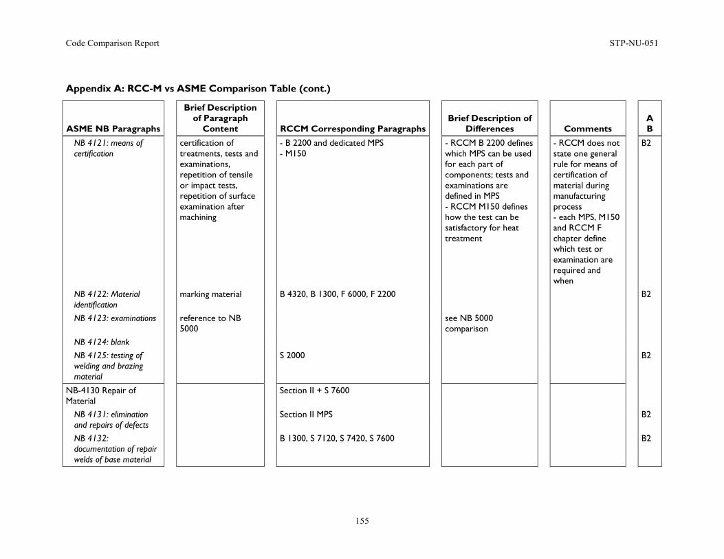
Code Comparison Report STP-NU-051
155
Appendix A: RCC-M vs ASME Comparison Table (cont.)
ASME NB Paragraphs
Brief Description of Paragraph
Content
RCCM Corresponding Paragraphs
Brief Description of Differences
Comments
A B
NB 4121: means of certification
certification of treatments, tests and examinations, repetition of tensile or impact tests, repetition of surface examination after machining
- B 2200 and dedicated MPS - M150
- RCCM B 2200 defines which MPS can be used for each part of components; tests and examinations are defined in MPS - RCCM M150 defines how the test can be satisfactory for heat treatment
- RCCM does not state one general rule for means of certification of material during manufacturing process - each MPS, M150 and RCCM F chapter define which test or examination are required and when
B2
NB 4122: Material identification
marking material B 4320, B 1300, F 6000, F 2200 B2
NB 4123: examinations reference to NB 5000
see NB 5000 comparison
NB 4124: blank NB 4125: testing of welding and brazing material
S 2000 B2
NB-4130 Repair of Material
Section II + S 7600
NB 4131: elimination and repairs of defects
Section II MPS B2
NB 4132: documentation of repair welds of base material
B 1300, S 7120, S 7420, S 7600 B2
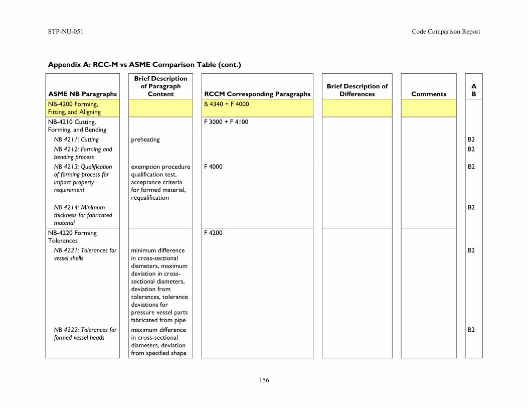
STP-NU-051 Code Comparison Report
156
Appendix A: RCC-M vs ASME Comparison Table (cont.)
ASME NB Paragraphs
Brief Description of Paragraph
Content
RCCM Corresponding Paragraphs
Brief Description of Differences
Comments
A B
NB-4200 Forming, Fitting, and Aligning
B 4340 + F 4000
NB-4210 Cutting, Forming, and Bending
F 3000 + F 4100
NB 4211: Cutting preheating B2 NB 4212: Forming and bending process
B2
NB 4213: Qualification of forming process for impact property requirement
exemption procedure qualification test, acceptance criteria for formed material, requalification
F 4000 B2
NB 4214: Minimum thickness for fabricated material
B2
NB-4220 Forming Tolerances
F 4200
NB 4221: Tolerances for vessel shells
minimum difference in cross-sectional diameters, maximum deviation in cross-sectional diameters, deviation from tolerances, tolerance deviations for pressure vessel parts fabricated from pipe
B2
NB 4222: Tolerances for formed vessel heads
maximum difference in cross-sectional diameters, deviation from specified shape
B2
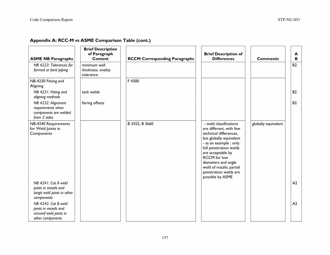
Code Comparison Report STP-NU-051
157
Appendix A: RCC-M vs ASME Comparison Table (cont.)
ASME NB Paragraphs
Brief Description of Paragraph
Content
RCCM Corresponding Paragraphs
Brief Description of Differences
Comments
A B
NB 4223: Tolerances for formed or bent piping
minimum wall thickness, ovality tolerance
B2
NB-4230 Fitting and Aligning
F 4300
NB 4231: Fitting and aligning methods
tack welds B2
NB 4232: Alignment requirements when components are welded from 2 sides
fairing offsets B2
NB-4240 Requirements for Weld Joints in Components
B 3352, B 3660 - weld classifications are different, with few technical differences, but globally equivalent - as an example : only full penetration welds are acceptable by RCCM for low diameters and angle weld of nozzle; partial penetration welds are possible by ASME
globally equivalent
NB 4241: Cat A weld joints in vessels and longit weld joints in other components
A2
NB 4242: Cat B weld joints in vessels and circumf weld joints in other components
A2
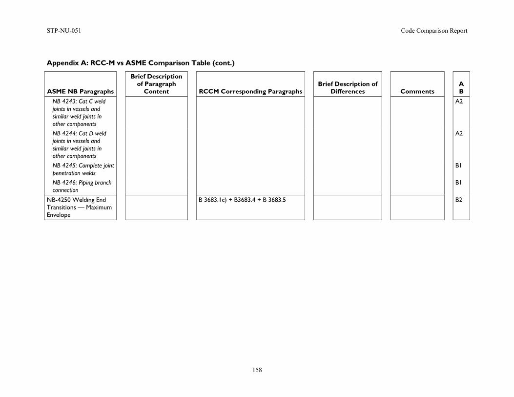
STP-NU-051 Code Comparison Report
158
Appendix A: RCC-M vs ASME Comparison Table (cont.)
ASME NB Paragraphs
Brief Description of Paragraph
Content
RCCM Corresponding Paragraphs
Brief Description of Differences
Comments
A B
NB 4243: Cat C weld joints in vessels and similar weld joints in other components
A2
NB 4244: Cat D weld joints in vessels and similar weld joints in other components
A2
NB 4245: Complete joint penetration welds
B1
NB 4246: Piping branch connection
B1
NB-4250 Welding End Transitions — Maximum Envelope
B 3683.1c) + B3683.4 + B 3683.5 B2
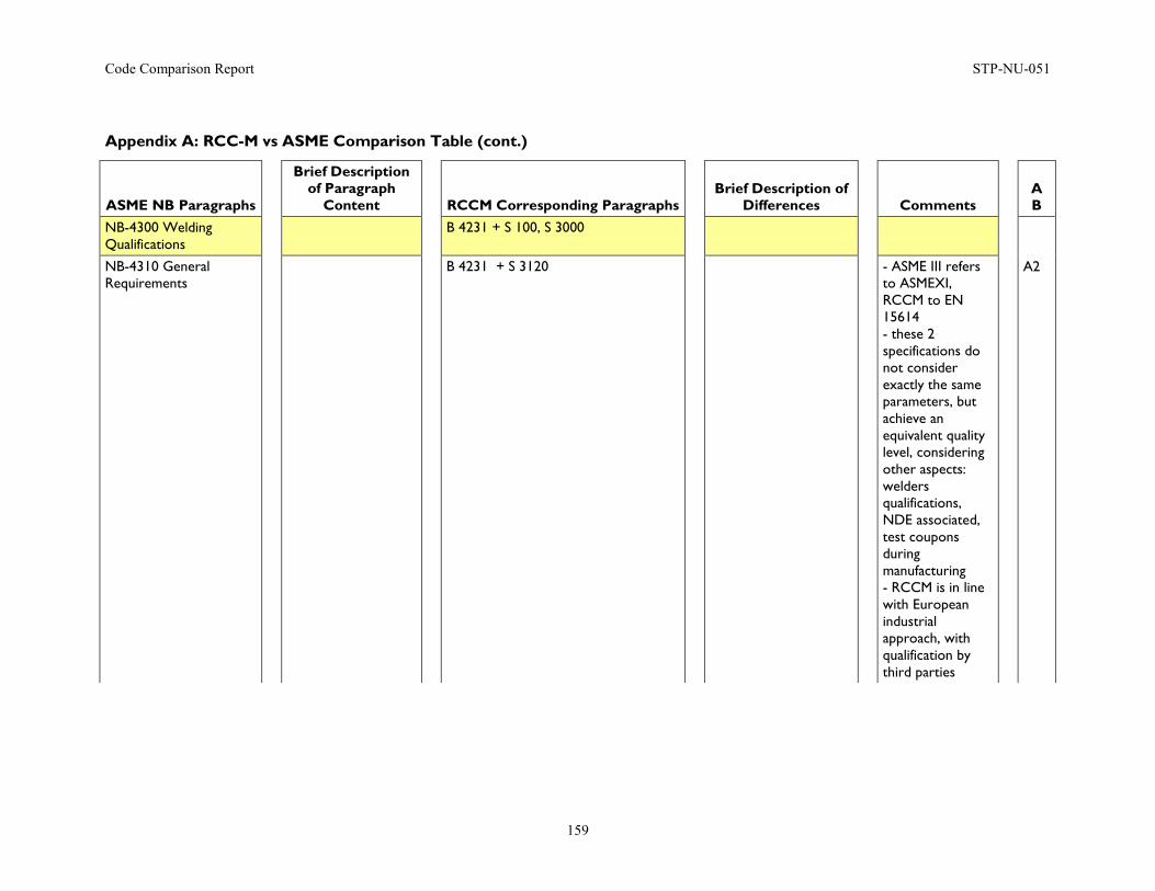
Code Comparison Report STP-NU-051
159
Appendix A: RCC-M vs ASME Comparison Table (cont.)
ASME NB Paragraphs
Brief Description of Paragraph
Content
RCCM Corresponding Paragraphs
Brief Description of Differences
Comments
A B
NB-4300 Welding Qualifications
B 4231 + S 100, S 3000
NB-4310 General Requirements
B 4231 + S 3120 - ASME III refers to ASMEXI, RCCM to EN 15614 - these 2 specifications do not consider exactly the same parameters, but achieve an equivalent quality level, considering other aspects: welders qualifications, NDE associated, test coupons during manufacturing - RCCM is in line with European industrial approach, with qualification by third parties
A2
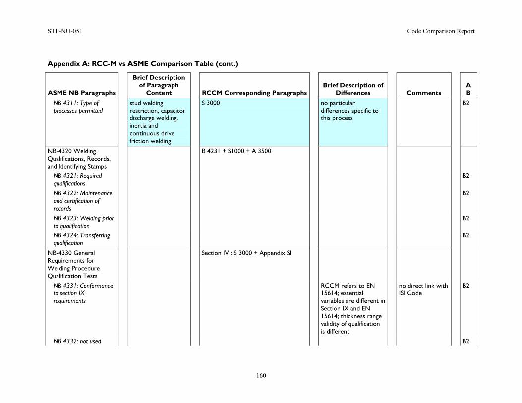
STP-NU-051 Code Comparison Report
160
Appendix A: RCC-M vs ASME Comparison Table (cont.)
ASME NB Paragraphs
Brief Description of Paragraph
Content
RCCM Corresponding Paragraphs
Brief Description of Differences
Comments
A B
NB 4311: Type of processes permitted
stud welding restriction, capacitor discharge welding, inertia and continuous drive friction welding
S 3000 no particular differences specific to this process
B2
NB-4320 Welding Qualifications, Records, and Identifying Stamps
B 4231 + S1000 + A 3500
NB 4321: Required qualifications
B2
NB 4322: Maintenance and certification of records
B2
NB 4323: Welding prior to qualification
B2
NB 4324: Transferring qualification
B2
NB-4330 General Requirements for Welding Procedure Qualification Tests
Section IV : S 3000 + Appendix SI
NB 4331: Conformance to section IX requirements
RCCM refers to EN 15614; essential variables are different in Section IX and EN 15614; thickness range validity of qualification is different
no direct link with ISI Code
B2
NB 4332: not used B2
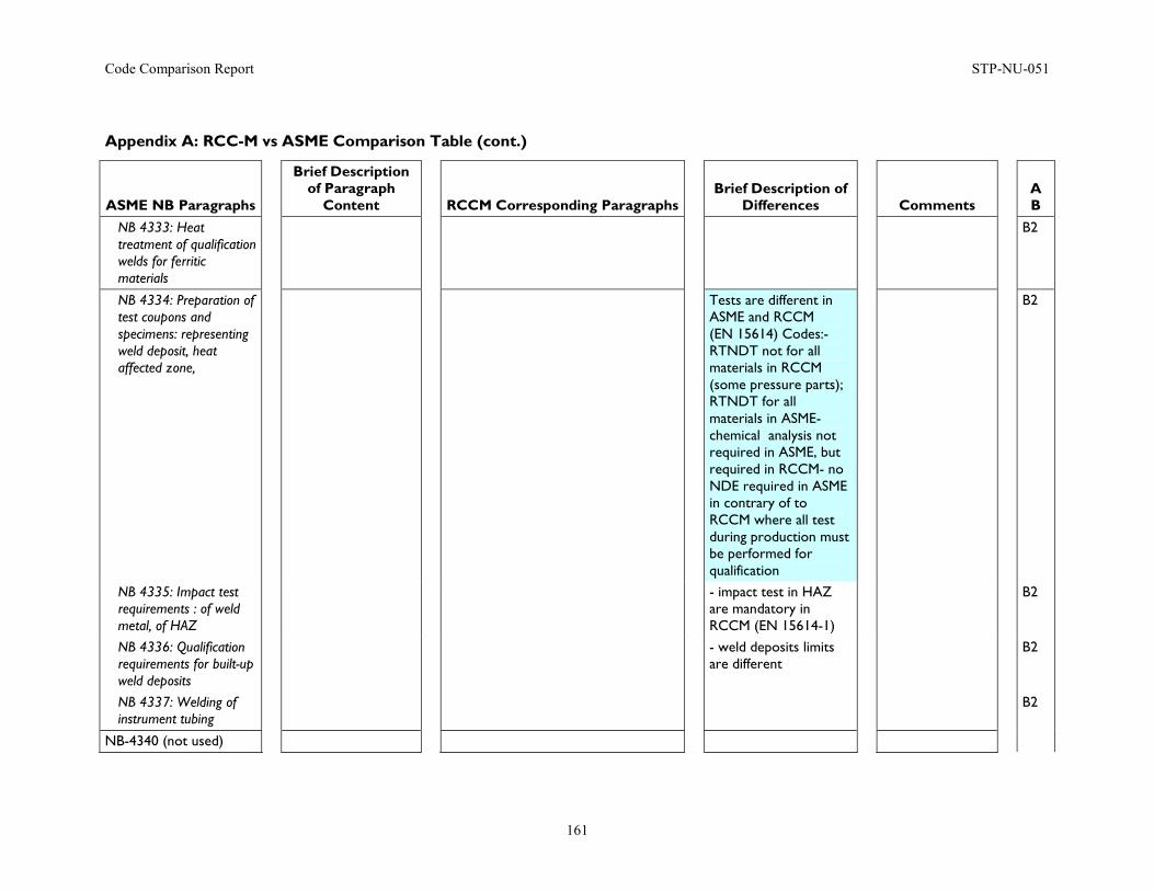
Code Comparison Report STP-NU-051
161
Appendix A: RCC-M vs ASME Comparison Table (cont.)
ASME NB Paragraphs
Brief Description of Paragraph
Content
RCCM Corresponding Paragraphs
Brief Description of Differences
Comments
A B
NB 4333: Heat treatment of qualification welds for ferritic materials
B2
NB 4334: Preparation of test coupons and specimens: representing weld deposit, heat affected zone,
Tests are different in ASME and RCCM (EN 15614) Codes:- RTNDT not for all materials in RCCM (some pressure parts); RTNDT for all materials in ASME- chemical analysis not required in ASME, but required in RCCM- no NDE required in ASME in contrary of to RCCM where all test during production must be performed for qualification
B2
NB 4335: Impact test requirements : of weld metal, of HAZ
- impact test in HAZ are mandatory in RCCM (EN 15614-1)
B2
NB 4336: Qualification requirements for built-up weld deposits
- weld deposits limits are different
B2
NB 4337: Welding of instrument tubing
B2
NB-4340 (not used)
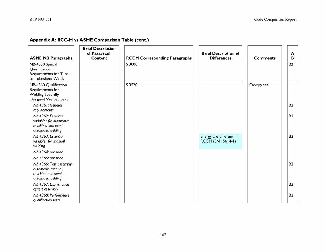
STP-NU-051 Code Comparison Report
162
Appendix A: RCC-M vs ASME Comparison Table (cont.)
ASME NB Paragraphs
Brief Description of Paragraph
Content
RCCM Corresponding Paragraphs
Brief Description of Differences
Comments
A B
NB-4350 Special Qualification Requirements for Tube-to-Tubesheet Welds
S 3800 B2
NB-4360 Qualification Requirements for Welding Specially Designed Welded Seals
S 3520 Canopy seal
NB 4361: General requirements
B2
NB 4362: Essential variables for automatic machine, and semi-automatic welding
B2
NB 4363: Essential variables for manual welding
Energy are different in RCCM (EN 15614-1)
B2
NB 4364: not used NB 4365: not used NB 4366: Test assembly: automatic, manual, machine and semi-automatic welding
B2
NB 4367: Examination of test assembly
B2
NB 4368: Performance qualification tests
B2
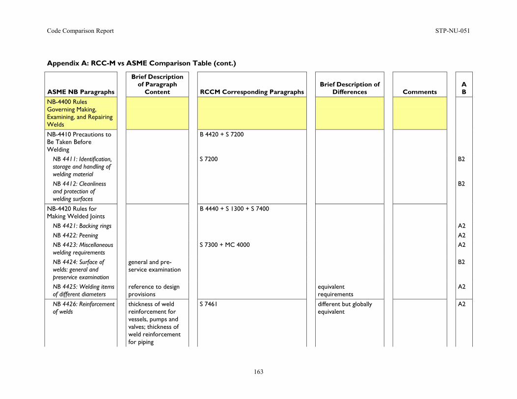
Code Comparison Report STP-NU-051
163
Appendix A: RCC-M vs ASME Comparison Table (cont.)
ASME NB Paragraphs
Brief Description of Paragraph
Content
RCCM Corresponding Paragraphs
Brief Description of Differences
Comments
A B
NB-4400 Rules Governing Making, Examining, and Repairing Welds
NB-4410 Precautions to Be Taken Before Welding
B 4420 + S 7200
NB 4411: Identification, storage and handling of welding material
S 7200 B2
NB 4412: Cleanliness and protection of welding surfaces
B2
NB-4420 Rules for Making Welded Joints
B 4440 + S 1300 + S 7400
NB 4421: Backing rings A2 NB 4422: Peening A2 NB 4423: Miscellaneous welding requirements
S 7300 + MC 4000 A2
NB 4424: Surface of welds: general and preservice examination
general and pre-service examination
B2
NB 4425: Welding items of different diameters
reference to design provisions
equivalent requirements
A2
NB 4426: Reinforcement of welds
thickness of weld reinforcement for vessels, pumps and valves; thickness of weld reinforcement for piping
S 7461 different but globally equivalent
A2
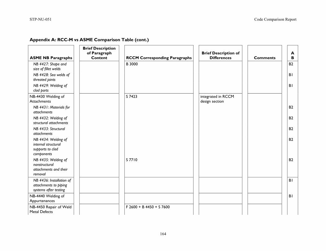
STP-NU-051 Code Comparison Report
164
Appendix A: RCC-M vs ASME Comparison Table (cont.)
ASME NB Paragraphs
Brief Description of Paragraph
Content
RCCM Corresponding Paragraphs
Brief Description of Differences
Comments
A B
NB 4427: Shape and size of fillet welds
B 3000 B2
NB 4428: Sea welds of threated joints
B1
NB 4429: Welding of clad parts
B1
NB-4430 Welding of Attachments
S 7423 integrated in RCCM design section
NB 4431: Materials for attachments
B2
NB 4432: Welding of structural attachments
B2
NB 4433: Structural attachments
B2
NB 4434: Welding of internal structural supports to clad components
B2
NB 4435: Welding of nonstructural attachments and their removal
S 7710 B2
NB 4436: Installation of attachments to piping systems after testing
B1
NB-4440 Welding of Appurtenances
B1
NB-4450 Repair of Weld Metal Defects
F 2600 + B 4450 + S 7600
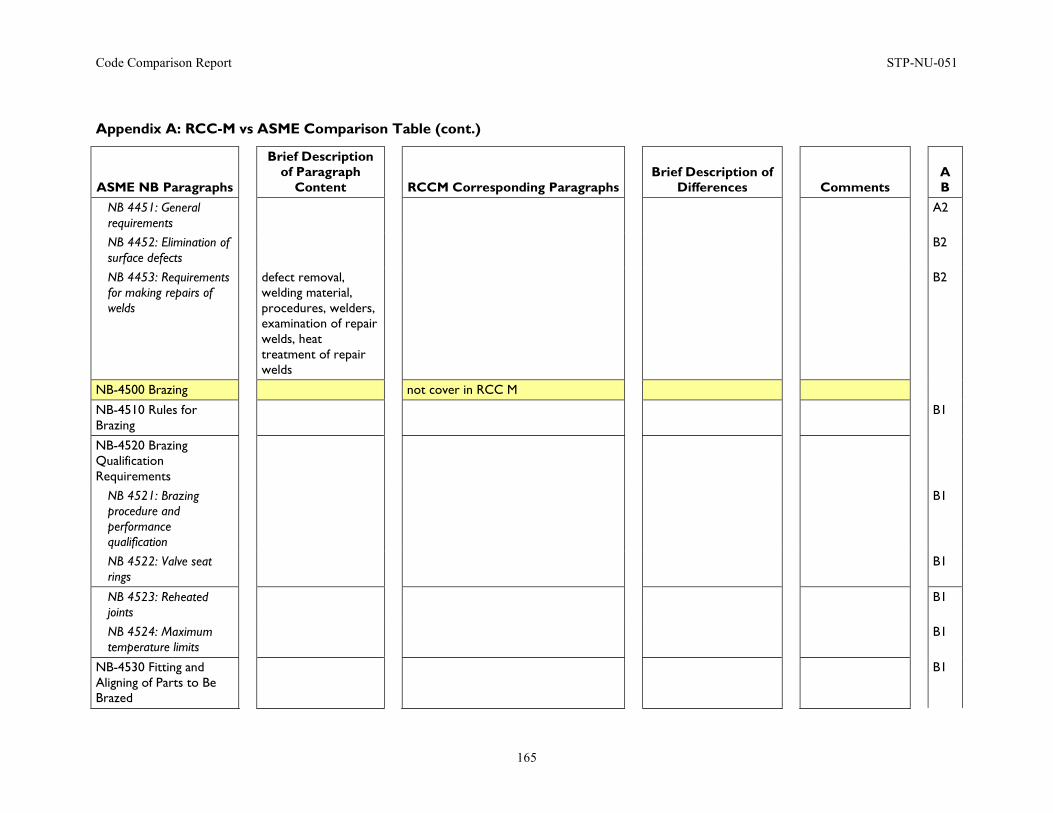
Code Comparison Report STP-NU-051
165
Appendix A: RCC-M vs ASME Comparison Table (cont.)
ASME NB Paragraphs
Brief Description of Paragraph
Content
RCCM Corresponding Paragraphs
Brief Description of Differences
Comments
A B
NB 4451: General requirements
A2
NB 4452: Elimination of surface defects
B2
NB 4453: Requirements for making repairs of welds
defect removal, welding material, procedures, welders, examination of repair welds, heat treatment of repair welds
B2
NB-4500 Brazing not cover in RCC M
NB-4510 Rules for Brazing
B1
NB-4520 Brazing Qualification Requirements
NB 4521: Brazing procedure and performance qualification
B1
NB 4522: Valve seat rings
B1
NB 4523: Reheated joints
B1
NB 4524: Maximum temperature limits
B1
NB-4530 Fitting and Aligning of Parts to Be Brazed
B1
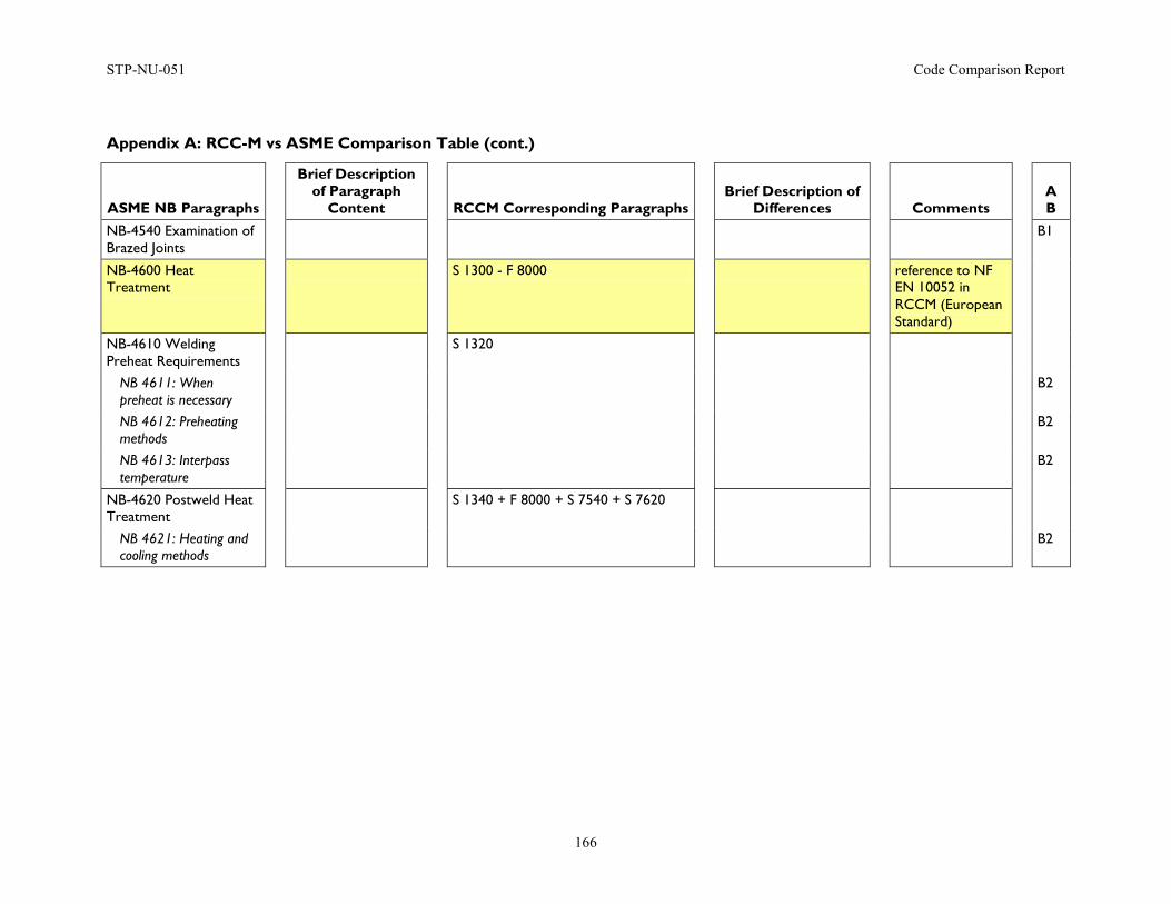
STP-NU-051 Code Comparison Report
166
Appendix A: RCC-M vs ASME Comparison Table (cont.)
ASME NB Paragraphs
Brief Description of Paragraph
Content
RCCM Corresponding Paragraphs
Brief Description of Differences
Comments
A B
NB-4540 Examination of Brazed Joints
B1
NB-4600 Heat Treatment
S 1300 - F 8000 reference to NF EN 10052 in RCCM (European Standard)
NB-4610 Welding Preheat Requirements
S 1320
NB 4611: When preheat is necessary
B2
NB 4612: Preheating methods
B2
NB 4613: Interpass temperature
B2
NB-4620 Postweld Heat Treatment
S 1340 + F 8000 + S 7540 + S 7620
NB 4621: Heating and cooling methods
B2
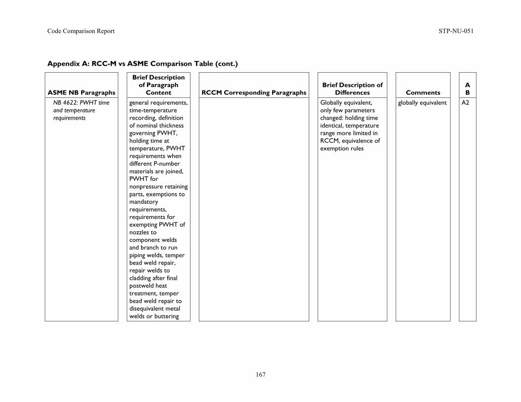
Code Comparison Report STP-NU-051
167
Appendix A: RCC-M vs ASME Comparison Table (cont.)
ASME NB Paragraphs
Brief Description of Paragraph
Content
RCCM Corresponding Paragraphs
Brief Description of Differences
Comments
A B
NB 4622: PWHT time and temperature requirements
general requirements, time-temperature recording, definition of nominal thickness governing PWHT, holding time at temperature, PWHT requirements when different P-number materials are joined, PWHT for nonpressure retaining parts, exemptions to mandatory requirements, requirements for exempting PWHT of nozzles to component welds and branch to run piping welds, temper bead weld repair, repair welds to cladding after final postweld heat treatment, temper bead weld repair to disequivalent metal welds or buttering
Globally equivalent, only few parameters changed: holding time identical, temperature range more limited in RCCM, equivalence of exemption rules
globally equivalent A2
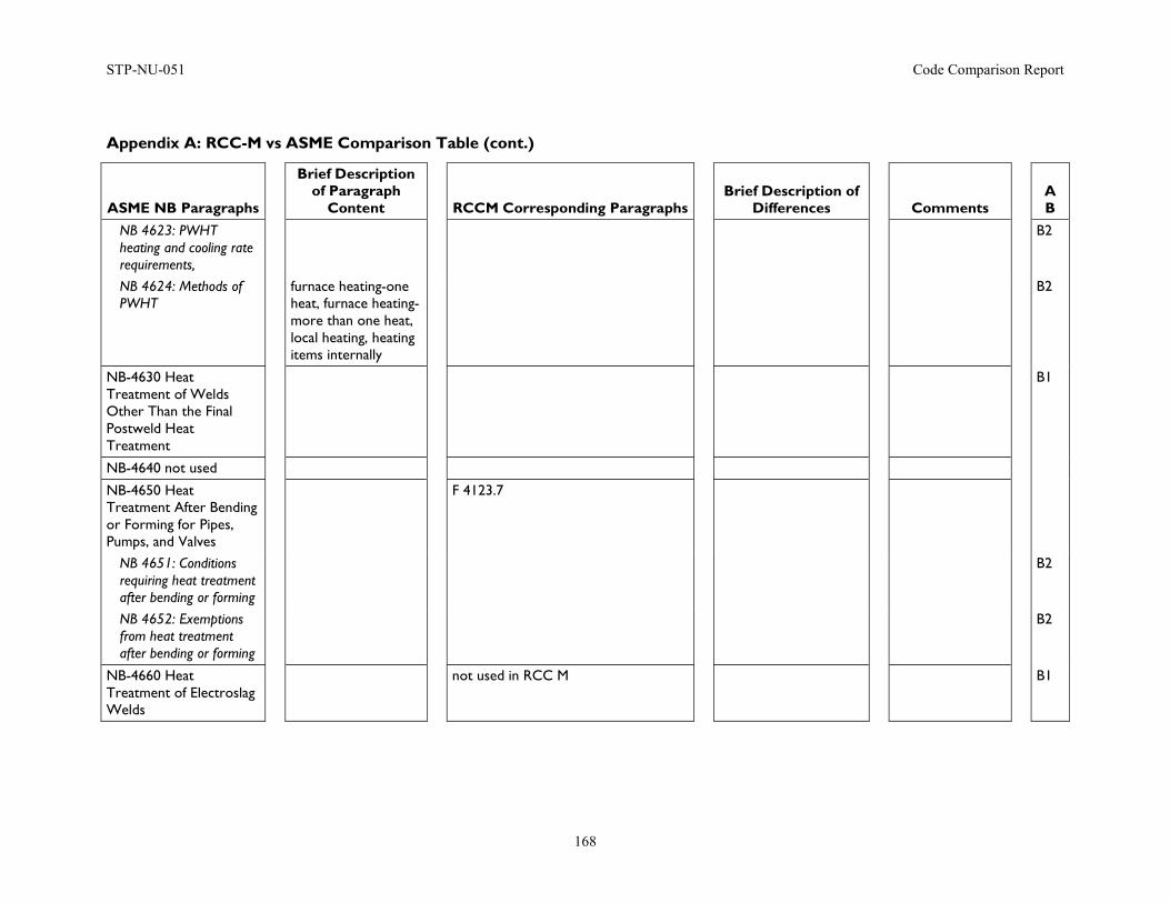
STP-NU-051 Code Comparison Report
168
Appendix A: RCC-M vs ASME Comparison Table (cont.)
ASME NB Paragraphs
Brief Description of Paragraph
Content
RCCM Corresponding Paragraphs
Brief Description of Differences
Comments
A B
NB 4623: PWHT heating and cooling rate requirements,
B2
NB 4624: Methods of PWHT
furnace heating-one heat, furnace heating- more than one heat, local heating, heating items internally
B2
NB-4630 Heat Treatment of Welds Other Than the Final Postweld Heat Treatment
B1
NB-4640 not used
NB-4650 Heat Treatment After Bending or Forming for Pipes, Pumps, and Valves
F 4123.7
NB 4651: Conditions requiring heat treatment after bending or forming
B2
NB 4652: Exemptions from heat treatment after bending or forming
B2
NB-4660 Heat Treatment of Electroslag Welds
not used in RCC M B1
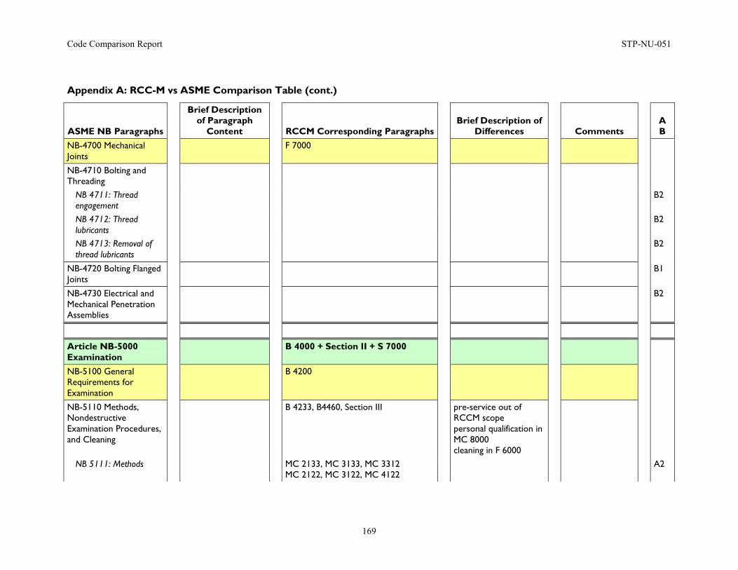
Code Comparison Report STP-NU-051
169
Appendix A: RCC-M vs ASME Comparison Table (cont.)
ASME NB Paragraphs
Brief Description of Paragraph
Content
RCCM Corresponding Paragraphs
Brief Description of Differences
Comments
A B
NB-4700 Mechanical Joints
F 7000
NB-4710 Bolting and Threading
NB 4711: Thread engagement
B2
NB 4712: Thread lubricants
B2
NB 4713: Removal of thread lubricants
B2
NB-4720 Bolting Flanged Joints
B1
NB-4730 Electrical and Mechanical Penetration Assemblies
B2
Article NB-5000 Examination
B 4000 + Section II + S 7000
NB-5100 General Requirements for Examination
B 4200
NB-5110 Methods, Nondestructive Examination Procedures, and Cleaning
B 4233, B4460, Section III pre-service out of RCCM scope personal qualification in MC 8000 cleaning in F 6000
NB 5111: Methods MC 2133, MC 3133, MC 3312 MC 2122, MC 3122, MC 4122
A2
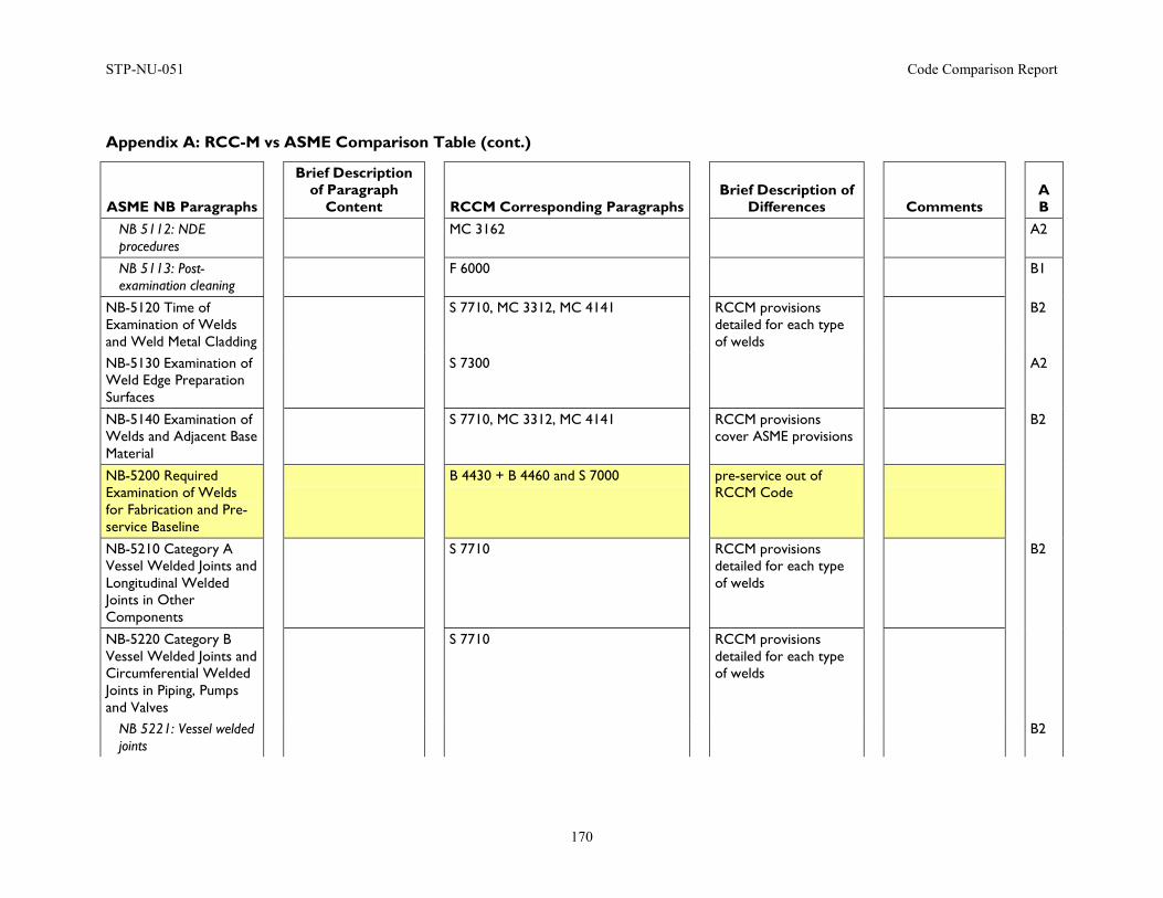
STP-NU-051 Code Comparison Report
170
Appendix A: RCC-M vs ASME Comparison Table (cont.)
ASME NB Paragraphs
Brief Description of Paragraph
Content
RCCM Corresponding Paragraphs
Brief Description of Differences
Comments
A B
NB 5112: NDE procedures
MC 3162 A2
NB 5113: Post-examination cleaning
F 6000 B1
NB-5120 Time of Examination of Welds and Weld Metal Cladding
S 7710, MC 3312, MC 4141 RCCM provisions detailed for each type of welds
B2
NB-5130 Examination of Weld Edge Preparation Surfaces
S 7300 A2
NB-5140 Examination of Welds and Adjacent Base Material
S 7710, MC 3312, MC 4141 RCCM provisions cover ASME provisions
B2
NB-5200 Required Examination of Welds for Fabrication and Pre-service Baseline
B 4430 + B 4460 and S 7000 pre-service out of RCCM Code
NB-5210 Category A Vessel Welded Joints and Longitudinal Welded Joints in Other Components
S 7710 RCCM provisions detailed for each type of welds
B2
NB-5220 Category B Vessel Welded Joints and Circumferential Welded Joints in Piping, Pumps and Valves
S 7710 RCCM provisions detailed for each type of welds
NB 5221: Vessel welded joints
B2
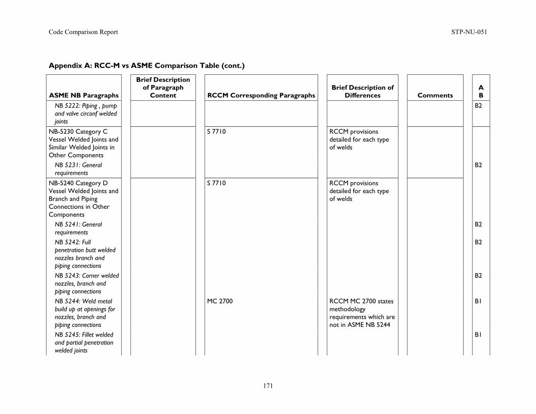
Code Comparison Report STP-NU-051
171
Appendix A: RCC-M vs ASME Comparison Table (cont.)
ASME NB Paragraphs
Brief Description of Paragraph
Content
RCCM Corresponding Paragraphs
Brief Description of Differences
Comments
A B
NB 5222: Piping , pump and valve circonf welded joints
B2
NB-5230 Category C Vessel Welded Joints and Similar Welded Joints in Other Components
S 7710 RCCM provisions detailed for each type of welds
NB 5231: General requirements
B2
NB-5240 Category D Vessel Welded Joints and Branch and Piping Connections in Other Components
S 7710 RCCM provisions detailed for each type of welds
NB 5241: General requirements
B2
NB 5242: Full penetration butt welded nozzles branch and piping connections
B2
NB 5243: Corner welded nozzles, branch and piping connections
B2
NB 5244: Weld metal build up at openings for nozzles, branch and piping connections
MC 2700 RCCM MC 2700 states methodology requirements which are not in ASME NB 5244
B1
NB 5245: Fillet welded and partial penetration welded joints
B1
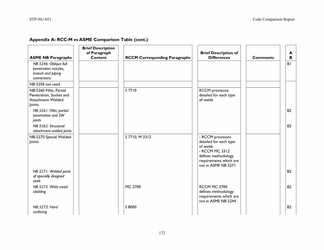
STP-NU-051 Code Comparison Report
172
Appendix A: RCC-M vs ASME Comparison Table (cont.)
ASME NB Paragraphs
Brief Description of Paragraph
Content
RCCM Corresponding Paragraphs
Brief Description of Differences
Comments
A B
NB 5246: Oblique full penetration nozzles, branch and piping connections
B1
NB 5250 not used
NB-5260 Fillet, Partial Penetration, Socket and Attachment Welded Joints
S 7710 RCCM provisions detailed for each type of welds
NB 5261: Fillet, partial penetration and SW joints
B2
NB 5262: Structural attachment welded joints
B2
NB-5270 Special Welded Joints
S 7710, M 3312 - RCCM provisions detailed for each type of welds - RCCM MC 3312 defines methodology requirements which are not in ASME NB 5271
NB 5271: Welded joints of specially designed seals
B2
NB 5272: Weld metal cladding
MC 2700 RCCM MC 2700 defines methodology requirements which are not in ASME NB 5244
B2
NB 5273: Hard surfacing
S 8000 B2
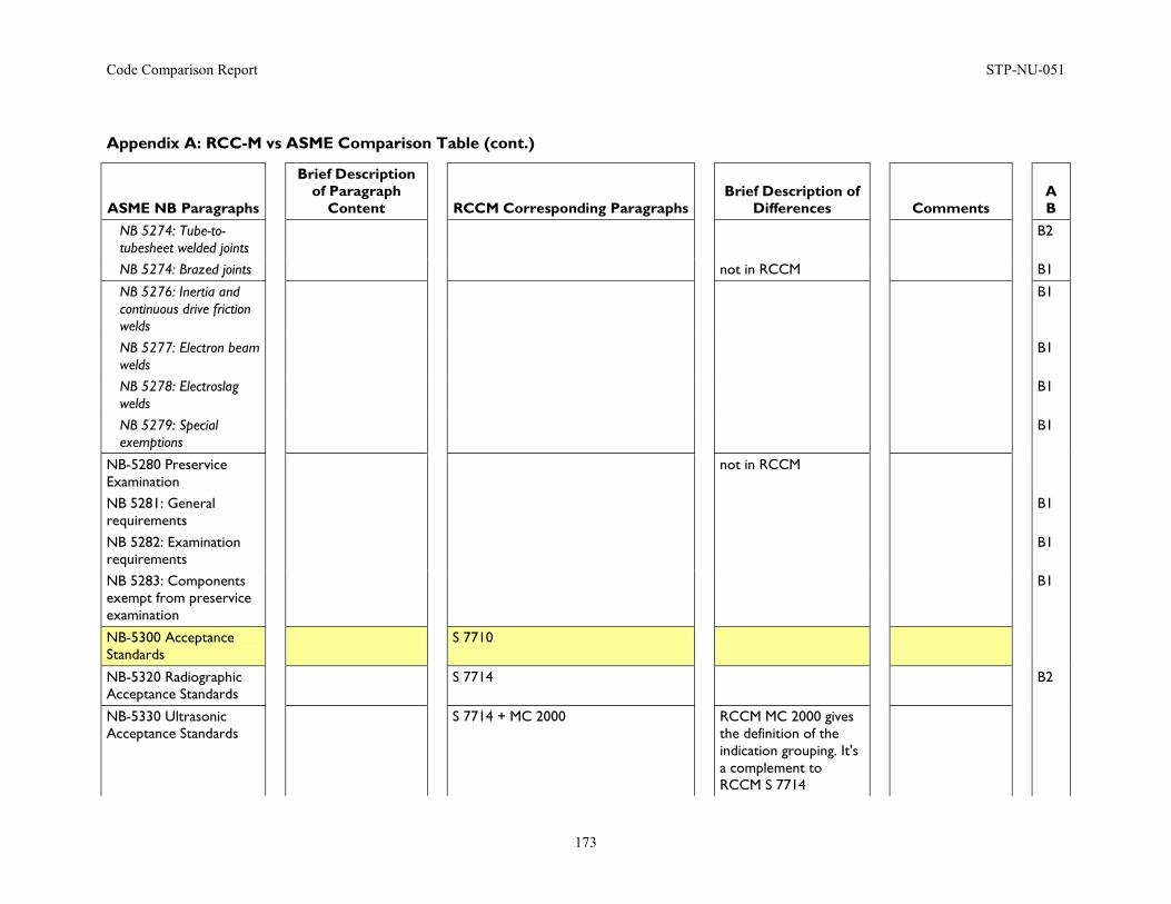
Code Comparison Report STP-NU-051
173
Appendix A: RCC-M vs ASME Comparison Table (cont.)
ASME NB Paragraphs
Brief Description of Paragraph
Content
RCCM Corresponding Paragraphs
Brief Description of Differences
Comments
A B
NB 5274: Tube-to-tubesheet welded joints
B2
NB 5274: Brazed joints not in RCCM B1
NB 5276: Inertia and continuous drive friction welds
B1
NB 5277: Electron beam welds
B1
NB 5278: Electroslag welds
B1
NB 5279: Special exemptions
B1
NB-5280 Preservice Examination
not in RCCM
NB 5281: General requirements
B1
NB 5282: Examination requirements
B1
NB 5283: Components exempt from preservice examination
B1
NB-5300 Acceptance Standards
S 7710
NB-5320 Radiographic Acceptance Standards
S 7714 B2
NB-5330 Ultrasonic Acceptance Standards
S 7714 + MC 2000 RCCM MC 2000 gives the definition of the indication grouping. It's a complement to RCCM S 7714
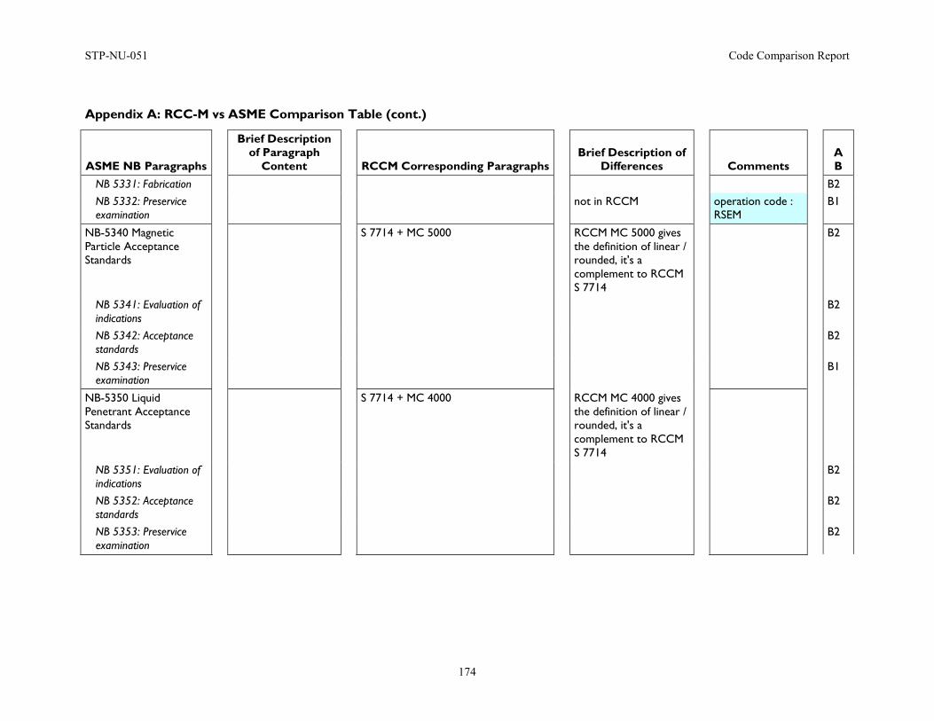
STP-NU-051 Code Comparison Report
174
Appendix A: RCC-M vs ASME Comparison Table (cont.)
ASME NB Paragraphs
Brief Description of Paragraph
Content
RCCM Corresponding Paragraphs
Brief Description of Differences
Comments
A B
NB 5331: Fabrication B2 NB 5332: Preservice examination
not in RCCM operation code : RSEM
B1
NB-5340 Magnetic Particle Acceptance Standards
S 7714 + MC 5000 RCCM MC 5000 gives the definition of linear / rounded, it's a complement to RCCM S 7714
B2
NB 5341: Evaluation of indications
B2
NB 5342: Acceptance standards
B2
NB 5343: Preservice examination
B1
NB-5350 Liquid Penetrant Acceptance Standards
S 7714 + MC 4000 RCCM MC 4000 gives the definition of linear / rounded, it's a complement to RCCM S 7714
NB 5351: Evaluation of indications
B2
NB 5352: Acceptance standards
B2
NB 5353: Preservice examination
B2
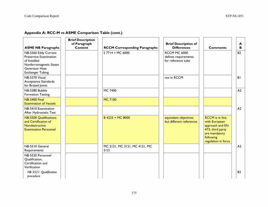
Code Comparison Report STP-NU-051
175
Appendix A: RCC-M vs ASME Comparison Table (cont.)
ASME NB Paragraphs
Brief Description of Paragraph
Content
RCCM Corresponding Paragraphs
Brief Description of Differences
Comments
A B
NB-5360 Eddy Current Preservice Examination of Installed Nonferromagnetic Steam Generator Heat Exchanger Tubing
S 7714 + MC 6000 RCCM MC 6000 defines requirements for reference tube
B2
NB-5370 Visual Acceptance Standards for Brazed Joints
not in RCCM B1
NB-5380 Bubble Formation Testing
MC 7400 A2
NB-5400 Final Examination of Vessels
MC 7100
NB-5410 Examination After Hydrostatic Test
A2
NB-5500 Qualifications and Certification of Nondestructive Examination Personnel
B 4233 + MC 8000 equivalent objectives, but different references
RCCM is in line with European approach and EN 473; third party are mandatory following regulation in force
NB-5510 General Requirements
MC 2121, MC 3121, MC 4121, MC 5121
A2
NB-5520 Personnel Qualification, Certification and Verification
NB 5521: Qualification procedure
B2

STP-NU-051 Code Comparison Report
176
Appendix A: RCC-M vs ASME Comparison Table (cont.)
ASME NB Paragraphs
Brief Description of Paragraph
Content
RCCM Corresponding Paragraphs
Brief Description of Differences
Comments
A B
NB 5522: Certification of personnel
B2
NB 5523: Verification of NDE personnel certification
B2
NB-5530 Records B2
Article NB-6000 Testing
B 5000
NB-6100 General Requirements
B 5100
NB-6110 Pressure Testing of Components, Appurtenances and Systems
NB 6111: Scope of pressure testing
preferred method : hydrostatic test, bolts, nuts, washers and gaskets exempted from pressure test
A2
NB 6112: Pneumatic testing: limitations, precautions
limitations, precautions
not applicable for class 1 components
non-mandatory appendix ZU might be used under cover of interpretation sheet
B2
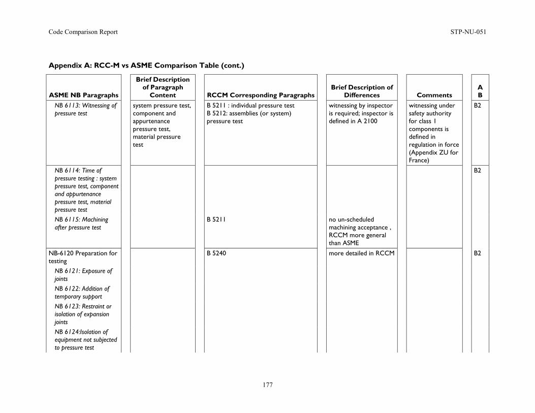
Code Comparison Report STP-NU-051
177
Appendix A: RCC-M vs ASME Comparison Table (cont.)
ASME NB Paragraphs
Brief Description of Paragraph
Content
RCCM Corresponding Paragraphs
Brief Description of Differences
Comments
A B
NB 6113: Witnessing of pressure test
system pressure test, component and appurtenance pressure test, material pressure test
B 5211 : individual pressure test B 5212: assemblies (or system) pressure test
witnessing by inspector is required; inspector is defined in A 2100
witnessing under safety authority for class 1 components is defined in regulation in force (Appendix ZU for France)
B2
NB 6114: Time of pressure testing : system pressure test, component and appurtenance pressure test, material pressure test
B2
NB 6115: Machining after pressure test
B 5211 no un-scheduled machining acceptance , RCCM more general than ASME
NB-6120 Preparation for testing
B 5240 more detailed in RCCM B2
NB 6121: Exposure of joints
NB 6122: Addition of temporary support
NB 6123: Restraint or isolation of expansion joints
NB 6124:Isolation of equipment not subjected to pressure test
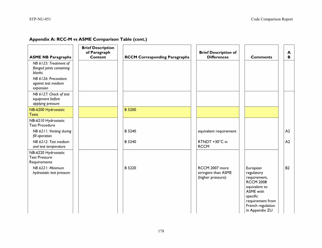
STP-NU-051 Code Comparison Report
178
Appendix A: RCC-M vs ASME Comparison Table (cont.)
ASME NB Paragraphs
Brief Description of Paragraph
Content
RCCM Corresponding Paragraphs
Brief Description of Differences
Comments
A B
NB 6125: Treatment of flanged joints containing blanks
NB 6126: Precautions against test medium expansion
NB 6127: Check of test equipment before applying pressure
NB-6200 Hydrostatic Tests
B 5200
NB-6210 Hydrostatic Test Procedure
NB 6211: Venting during fill operation
B 5240 equivalent requirement A2
NB 6212: Test medium and test temperature
B 5240 RTNDT +30°C in RCCM
A2
NB-6220 Hydrostatic Test Pressure Requirements
NB 6221: Minimum hydrostatic test pressure
B 5220 RCCM 2007 more stringent than ASME (higher pressure)
European regulatory requirement, RCCM 2008 equivalent to ASME with specific requirement from French regulation in Appendix ZU
B2
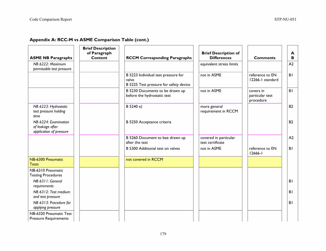
Code Comparison Report STP-NU-051
179
Appendix A: RCC-M vs ASME Comparison Table (cont.)
ASME NB Paragraphs
Brief Description of Paragraph
Content
RCCM Corresponding Paragraphs
Brief Description of Differences
Comments
A B
NB 6222: Maximum permissible test pressure
equivalent stress limits A2
B 5223 Individual test pressure for valve B 5225 Test pressure for safety device
not in ASME reference to EN 12266-1 standard
B1
B 5230 Documents to be drawn up before the hydrostatic test
not in ASME covers in particular test procedure
B1
NB 6223: Hydrostatic test pressure holding time
B 5240 e) more general requirement in RCCM
B2
NB 6224: Examination of leakage after application of pressure
B 5250 Acceptance criteria B2
B 5260 Document to bee drawn up after the test
covered in particular test certificate
A2
B 5300 Additional test on valves not in ASME reference to EN 12666-1
B1
NB-6300 Pneumatic Tests
not covered in RCCM
NB-6310 Pneumatic Testing Procedures
NB 6311: General requirements
B1
NB 6312: Test medium and test pressure
B1
NB 6313: Procedure for applying pressure
B1
NB-6320 Pneumatic Test Pressure Requirements
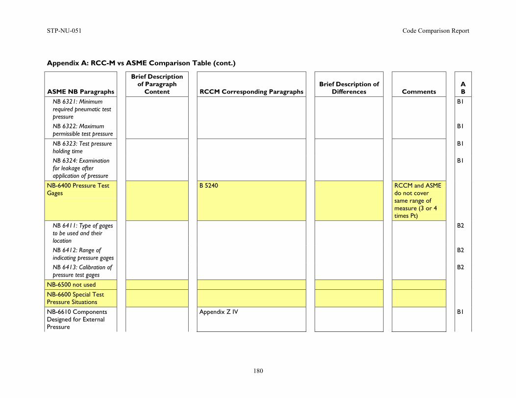
STP-NU-051 Code Comparison Report
180
Appendix A: RCC-M vs ASME Comparison Table (cont.)
ASME NB Paragraphs
Brief Description of Paragraph
Content
RCCM Corresponding Paragraphs
Brief Description of Differences
Comments
A B
NB 6321: Minimum required pneumatic test pressure
B1
NB 6322: Maximum permissible test pressure
B1
NB 6323: Test pressure holding time
B1
NB 6324: Examination for leakage after application of pressure
B1
NB-6400 Pressure Test Gages
B 5240 RCCM and ASME do not cover same range of measure (3 or 4 times Pt)
NB 6411: Type of gages to be used and their location
B2
NB 6412: Range of indicating pressure gages
B2
NB 6413: Calibration of pressure test gages
B2
NB-6500 not used
NB-6600 Special Test Pressure Situations
NB-6610 Components Designed for External Pressure
Appendix Z IV B1
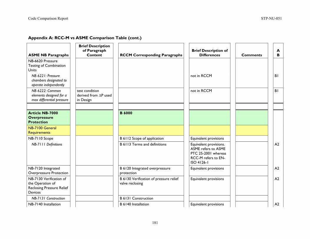
Code Comparison Report STP-NU-051
181
Appendix A: RCC-M vs ASME Comparison Table (cont.)
ASME NB Paragraphs
Brief Description of Paragraph
Content
RCCM Corresponding Paragraphs
Brief Description of Differences
Comments
A B
NB-6620 Pressure Testing of Combination Units
NB 6221: Pressure chambers designated to operate independently
not in RCCM B1
NB 6222: Common elements designed for a max differential pressure
test condition derived from ΔP used in Design
not in RCCM B1
Article NB-7000 Overpressure Protection
B 6000
NB-7100 General Requirements
NB-7110 Scope B 6112 Scope of application Equivalent provisions
NB-7111 Definitions B 6113 Terms and definitions Equivalent provisions. ASME refers to ASME PTC 25-2001 whereas RCC-M refers to EN-ISO 4126-1
A2
NB-7120 Integrated Overpressure Protection
B 6120 Integrated overpressure protection
Equivalent provisions A2
NB-7130 Verification of the Operation of Reclosing Pressure Relief Devices
B 6130 Verification of pressure relief valve reclosing
Equivalent provisions A2
NB-7131 Construction B 6131 Construction
NB-7140 Installation B 6140 Installation Equivalent provisions A2
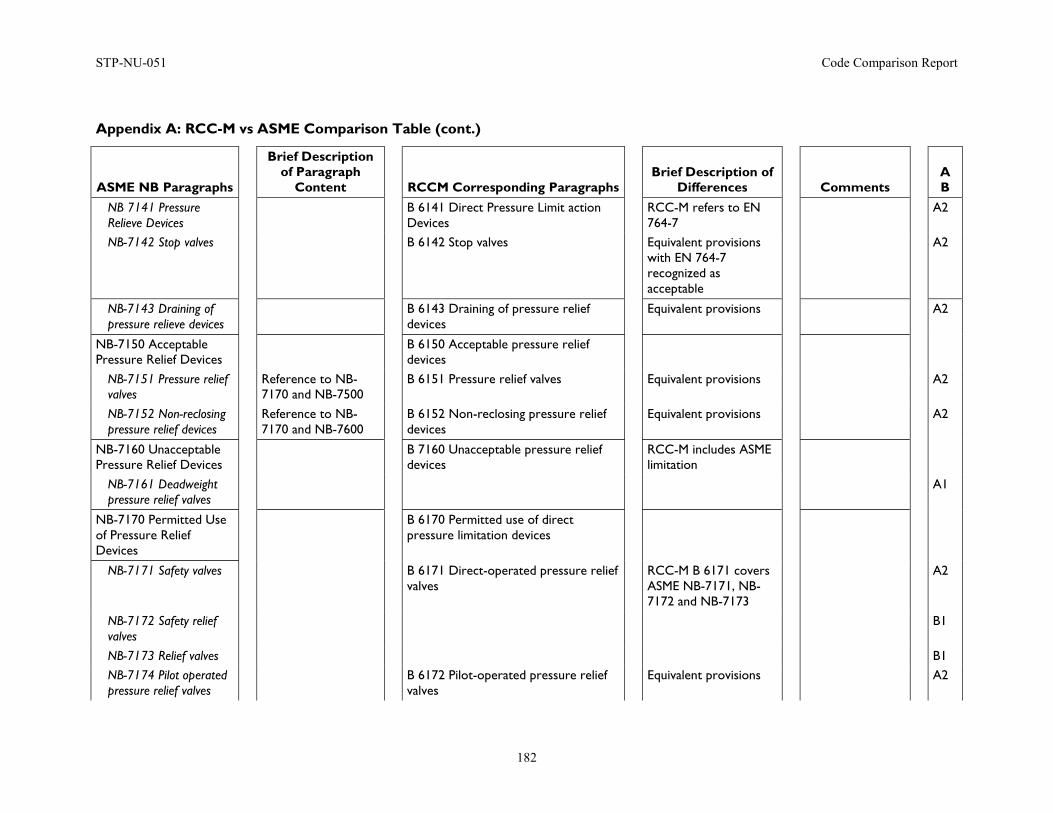
STP-NU-051 Code Comparison Report
182
Appendix A: RCC-M vs ASME Comparison Table (cont.)
ASME NB Paragraphs
Brief Description of Paragraph
Content
RCCM Corresponding Paragraphs
Brief Description of Differences
Comments
A B
NB 7141 Pressure Relieve Devices
B 6141 Direct Pressure Limit action Devices
RCC-M refers to EN 764-7
A2
NB-7142 Stop valves B 6142 Stop valves Equivalent provisions with EN 764-7 recognized as acceptable
A2
NB-7143 Draining of pressure relieve devices
B 6143 Draining of pressure relief devices
Equivalent provisions A2
NB-7150 Acceptable Pressure Relief Devices
B 6150 Acceptable pressure relief devices
NB-7151 Pressure relief valves
Reference to NB-7170 and NB-7500
B 6151 Pressure relief valves Equivalent provisions A2
NB-7152 Non-reclosing pressure relief devices
Reference to NB-7170 and NB-7600
B 6152 Non-reclosing pressure relief devices
Equivalent provisions A2
NB-7160 Unacceptable Pressure Relief Devices
B 7160 Unacceptable pressure relief devices
RCC-M includes ASME limitation
NB-7161 Deadweight pressure relief valves
A1
NB-7170 Permitted Use of Pressure Relief Devices
B 6170 Permitted use of direct pressure limitation devices
NB-7171 Safety valves B 6171 Direct-operated pressure relief valves
RCC-M B 6171 covers ASME NB-7171, NB-7172 and NB-7173
A2
NB-7172 Safety relief valves
B1
NB-7173 Relief valves B1 NB-7174 Pilot operated pressure relief valves
B 6172 Pilot-operated pressure relief valves
Equivalent provisions A2
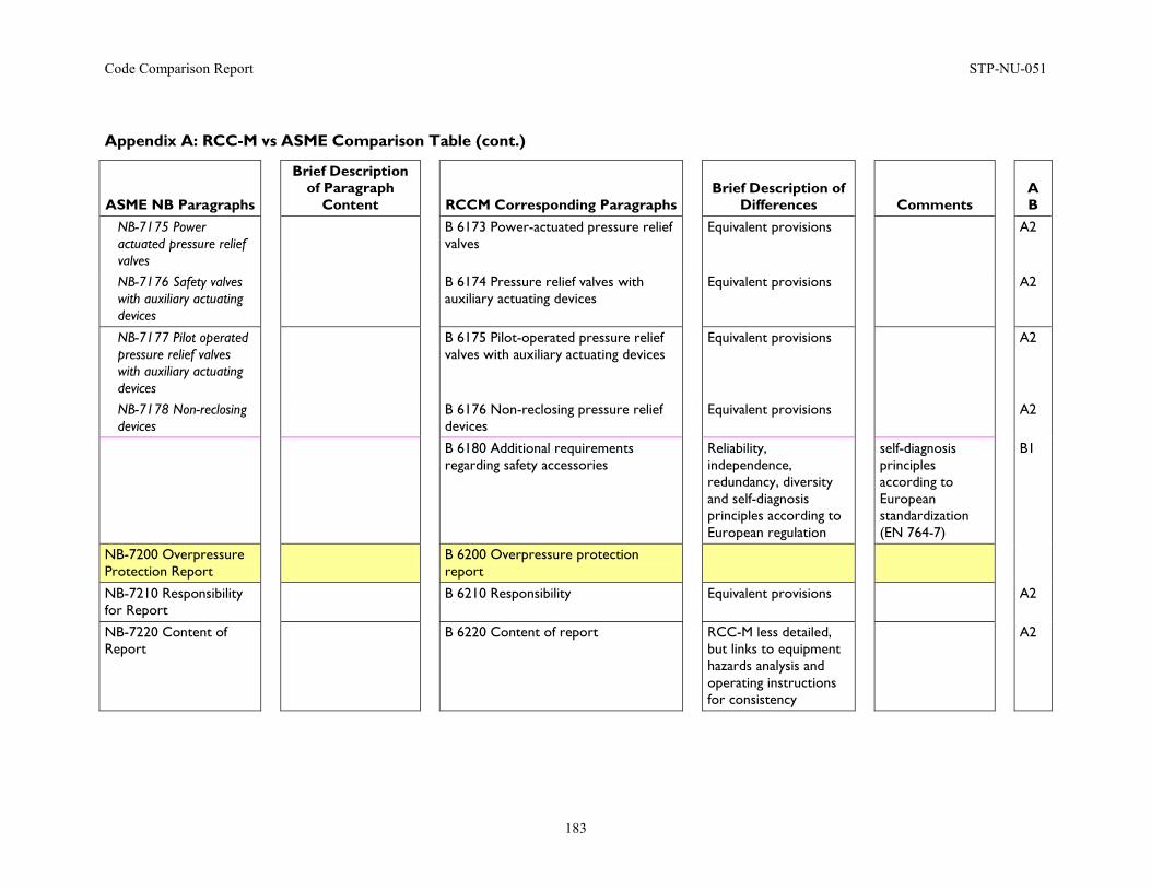
Code Comparison Report STP-NU-051
183
Appendix A: RCC-M vs ASME Comparison Table (cont.)
ASME NB Paragraphs
Brief Description of Paragraph
Content
RCCM Corresponding Paragraphs
Brief Description of Differences
Comments
A B
NB-7175 Power actuated pressure relief valves
B 6173 Power-actuated pressure relief valves
Equivalent provisions A2
NB-7176 Safety valves with auxiliary actuating devices
B 6174 Pressure relief valves with auxiliary actuating devices
Equivalent provisions A2
NB-7177 Pilot operated pressure relief valves with auxiliary actuating devices
B 6175 Pilot-operated pressure relief valves with auxiliary actuating devices
Equivalent provisions A2
NB-7178 Non-reclosing devices
B 6176 Non-reclosing pressure relief devices
Equivalent provisions A2
B 6180 Additional requirements regarding safety accessories
Reliability, independence, redundancy, diversity and self-diagnosis principles according to European regulation
self-diagnosis principles according to European standardization (EN 764-7)
B1
NB-7200 Overpressure Protection Report
B 6200 Overpressure protection report
NB-7210 Responsibility for Report
B 6210 Responsibility Equivalent provisions A2
NB-7220 Content of Report
B 6220 Content of report RCC-M less detailed, but links to equipment hazards analysis and operating instructions for consistency
A2
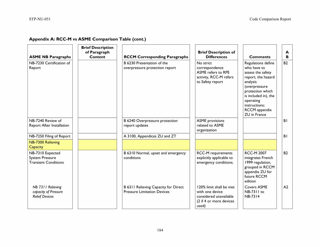
STP-NU-051 Code Comparison Report
184
Appendix A: RCC-M vs ASME Comparison Table (cont.)
ASME NB Paragraphs
Brief Description of Paragraph
Content
RCCM Corresponding Paragraphs
Brief Description of Differences
Comments
A B
NB-7230 Certification of Report
B 6230 Presentation of the overpressure protection report
No strict correspondence ASME refers to RPE activity, RCC-M refers to Safety report
Regulations define who have to assess the safety report, the hazard analysis (overpressure protection which is included in), the operating instructions; RCCM appendix ZU in France
B2
NB-7240 Review of Report After Installation
B 6240 Overpressure protection report updates
ASME provisions related to ASME organization
B1
NB-7250 Filing of Report A 3100, Appendices ZU and ZT B1
NB-7300 Relieving Capacity
NB-7310 Expected System Pressure Transient Conditions
B 6310 Normal, upset and emergency conditions
RCC-M requirements explicitly applicable to emergency conditions.
RCC-M 2007 integrates French 1999 regulation, grouped in RCCM appendix ZU for future RCCM edition
B2
NB 7311 Relieving capacity of Pressure Relief Devices
B 6311 Relieving Capacity for Direct Pressure Limitation Devices
120% limit shall be met with one device considered unavailable (2 if 4 or more devices used)
Covers ASME NB-7311 to NB-7314
A2
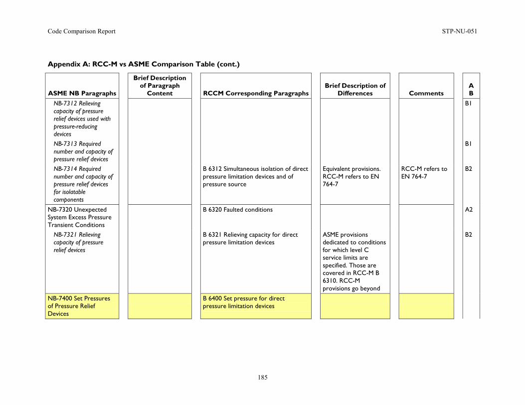
Code Comparison Report STP-NU-051
185
Appendix A: RCC-M vs ASME Comparison Table (cont.)
ASME NB Paragraphs
Brief Description of Paragraph
Content
RCCM Corresponding Paragraphs
Brief Description of Differences
Comments
A B
NB-7312 Relieving capacity of pressure relief devices used with pressure-reducing devices
B1
NB-7313 Required number and capacity of pressure relief devices
B1
NB-7314 Required number and capacity of pressure relief devices for isolatable components
B 6312 Simultaneous isolation of direct pressure limitation devices and of pressure source
Equivalent provisions. RCC-M refers to EN 764-7
RCC-M refers to EN 764-7
B2
NB-7320 Unexpected System Excess Pressure Transient Conditions
B 6320 Faulted conditions A2
NB-7321 Relieving capacity of pressure relief devices
B 6321 Relieving capacity for direct pressure limitation devices
ASME provisions dedicated to conditions for which level C service limits are specified. Those are covered in RCC-M B 6310. RCC-M provisions go beyond
B2
NB-7400 Set Pressures of Pressure Relief Devices
B 6400 Set pressure for direct pressure limitation devices
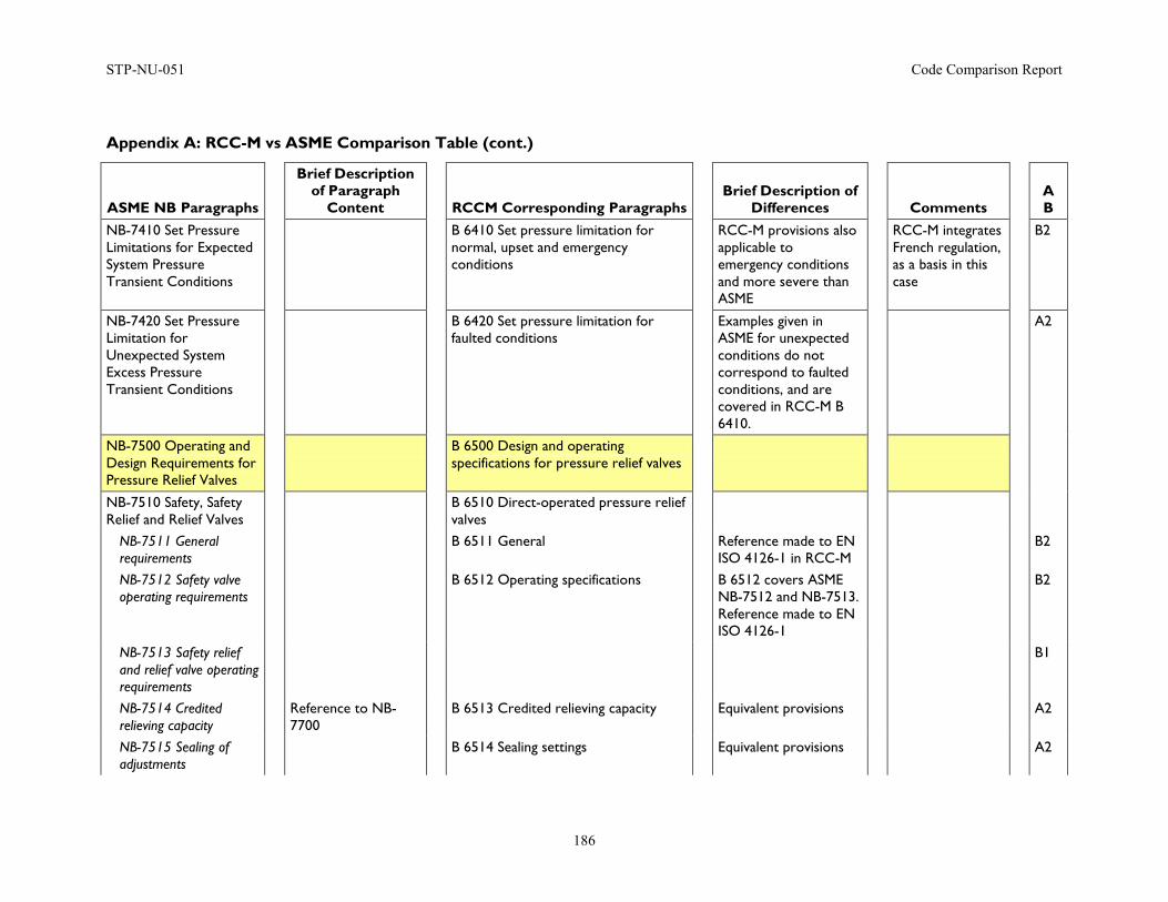
STP-NU-051 Code Comparison Report
186
Appendix A: RCC-M vs ASME Comparison Table (cont.)
ASME NB Paragraphs
Brief Description of Paragraph
Content
RCCM Corresponding Paragraphs
Brief Description of Differences
Comments
A B
NB-7410 Set Pressure Limitations for Expected System Pressure Transient Conditions
B 6410 Set pressure limitation for normal, upset and emergency conditions
RCC-M provisions also applicable to emergency conditions and more severe than ASME
RCC-M integrates French regulation, as a basis in this case
B2
NB-7420 Set Pressure Limitation for Unexpected System Excess Pressure Transient Conditions
B 6420 Set pressure limitation for faulted conditions
Examples given in ASME for unexpected conditions do not correspond to faulted conditions, and are covered in RCC-M B 6410.
A2
NB-7500 Operating and Design Requirements for Pressure Relief Valves
B 6500 Design and operating specifications for pressure relief valves
NB-7510 Safety, Safety Relief and Relief Valves
B 6510 Direct-operated pressure relief valves
NB-7511 General requirements
B 6511 General Reference made to EN ISO 4126-1 in RCC-M
B2
NB-7512 Safety valve operating requirements
B 6512 Operating specifications B 6512 covers ASME NB-7512 and NB-7513. Reference made to EN ISO 4126-1
B2
NB-7513 Safety relief and relief valve operating requirements
B1
NB-7514 Credited relieving capacity
Reference to NB-7700
B 6513 Credited relieving capacity Equivalent provisions A2
NB-7515 Sealing of adjustments
B 6514 Sealing settings Equivalent provisions A2
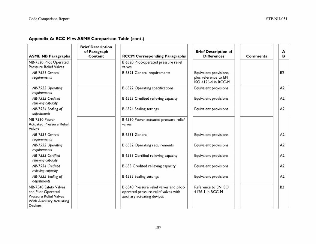
Code Comparison Report STP-NU-051
187
Appendix A: RCC-M vs ASME Comparison Table (cont.)
ASME NB Paragraphs
Brief Description of Paragraph
Content
RCCM Corresponding Paragraphs
Brief Description of Differences
Comments
A B
NB-7520 Pilot Operated Pressure Relief Valves
B 6520 Pilot-operated pressure relief valves
NB-7521 General requirements
B 6521 General requirements Equivalent provisions, plus reference to EN ISO 4126-4 in RCC-M
B2
NB-7522 Operating requirements
B 6522 Operating specifications Equivalent provisions A2
NB-7523 Credited relieving capacity
B 6523 Credited relieving capacity Equivalent provisions A2
NB-7524 Sealing of adjustments
B 6524 Sealing settings Equivalent provisions A2
NB-7530 Power Actuated Pressure Relief Valves
B 6530 Power-actuated pressure relief valves
NB-7531 General requirements
B 6531 General Equivalent provisions A2
NB-7532 Operating requirements
B 6532 Operating requirements Equivalent provisions A2
NB-7533 Certified relieving capacity
B 6533 Certified relieving capacity Equivalent provisions A2
NB-7534 Credited relieving capacity
B 653 Credited relieving capacity Equivalent provisions A2
NB-7535 Sealing of adjustments
B 6535 Sealing settings Equivalent provisions A2
NB-7540 Safety Valves and Pilot Operated Pressure Relief Valves With Auxiliary Actuating Devices
B 6540 Pressure relief valves and pilot-operated pressure-relief valves with auxiliary actuating devices
Reference to EN ISO 4126-1 in RCC-M
B2
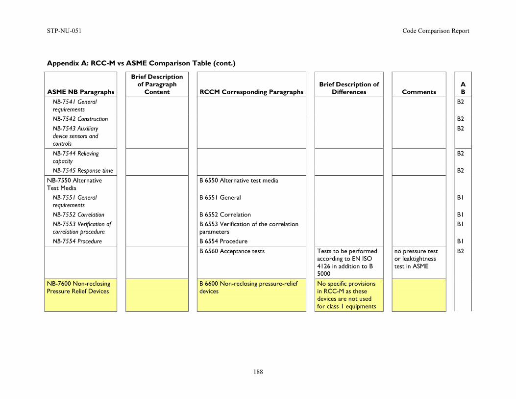
STP-NU-051 Code Comparison Report
188
Appendix A: RCC-M vs ASME Comparison Table (cont.)
ASME NB Paragraphs
Brief Description of Paragraph
Content
RCCM Corresponding Paragraphs
Brief Description of Differences
Comments
A B
NB-7541 General requirements
B2
NB-7542 Construction B2 NB-7543 Auxiliary device sensors and controls
B2
NB-7544 Relieving capacity
B2
NB-7545 Response time B2
NB-7550 Alternative Test Media
B 6550 Alternative test media
NB-7551 General requirements
B 6551 General B1
NB-7552 Correlation B 6552 Correlation B1 NB-7553 Verification of correlation procedure
B 6553 Verification of the correlation parameters
B1
NB-7554 Procedure B 6554 Procedure B1
B 6560 Acceptance tests Tests to be performed according to EN ISO 4126 in addition to B 5000
no pressure test or leaktightness test in ASME
B2
NB-7600 Non-reclosing Pressure Relief Devices
B 6600 Non-reclosing pressure-relief devices
No specific provisions in RCC-M as these devices are not used for class 1 equipments
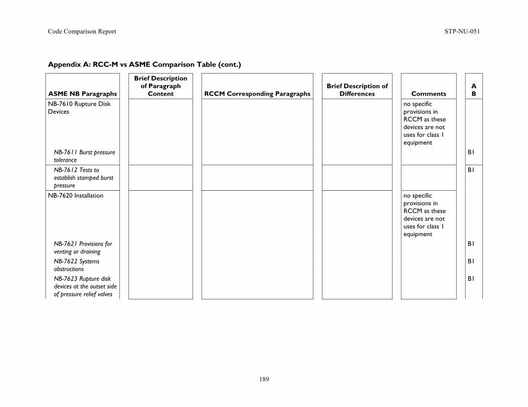
Code Comparison Report STP-NU-051
189
Appendix A: RCC-M vs ASME Comparison Table (cont.)
ASME NB Paragraphs
Brief Description of Paragraph
Content
RCCM Corresponding Paragraphs
Brief Description of Differences
Comments
A B
NB-7610 Rupture Disk Devices
no specific provisions in RCCM as these devices are not uses for class 1 equipment
NB-7611 Burst pressure tolerance
B1
NB-7612 Tests to establish stamped burst pressure
B1
NB-7620 Installation no specific provisions in RCCM as these devices are not uses for class 1 equipment
NB-7621 Provisions for venting or draining
B1
NB-7622 Systems obstructions
B1
NB-7623 Rupture disk devices at the outset side of pressure relief valves
B1
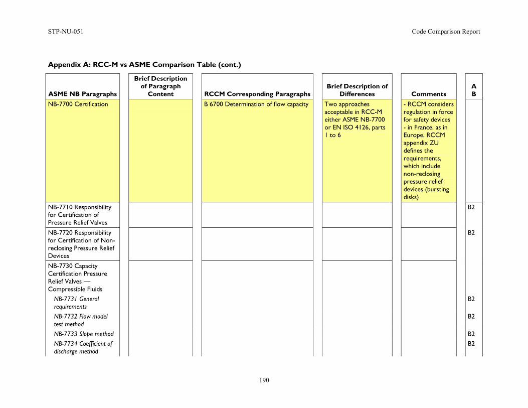
STP-NU-051 Code Comparison Report
190
Appendix A: RCC-M vs ASME Comparison Table (cont.)
ASME NB Paragraphs
Brief Description of Paragraph
Content
RCCM Corresponding Paragraphs
Brief Description of Differences
Comments
A B
NB-7700 Certification B 6700 Determination of flow capacity Two approaches acceptable in RCC-M either ASME NB-7700 or EN ISO 4126, parts 1 to 6
- RCCM considers regulation in force for safety devices - in France, as in Europe, RCCM appendix ZU defines the requirements, which include non-reclosing pressure relief devices (bursting disks)
NB-7710 Responsibility for Certification of Pressure Relief Valves
B2
NB-7720 Responsibility for Certification of Non-reclosing Pressure Relief Devices
B2
NB-7730 Capacity Certification Pressure Relief Valves — Compressible Fluids
NB-7731 General requirements
B2
NB-7732 Flow model test method
B2
NB-7733 Slope method B2 NB-7734 Coefficient of discharge method
B2
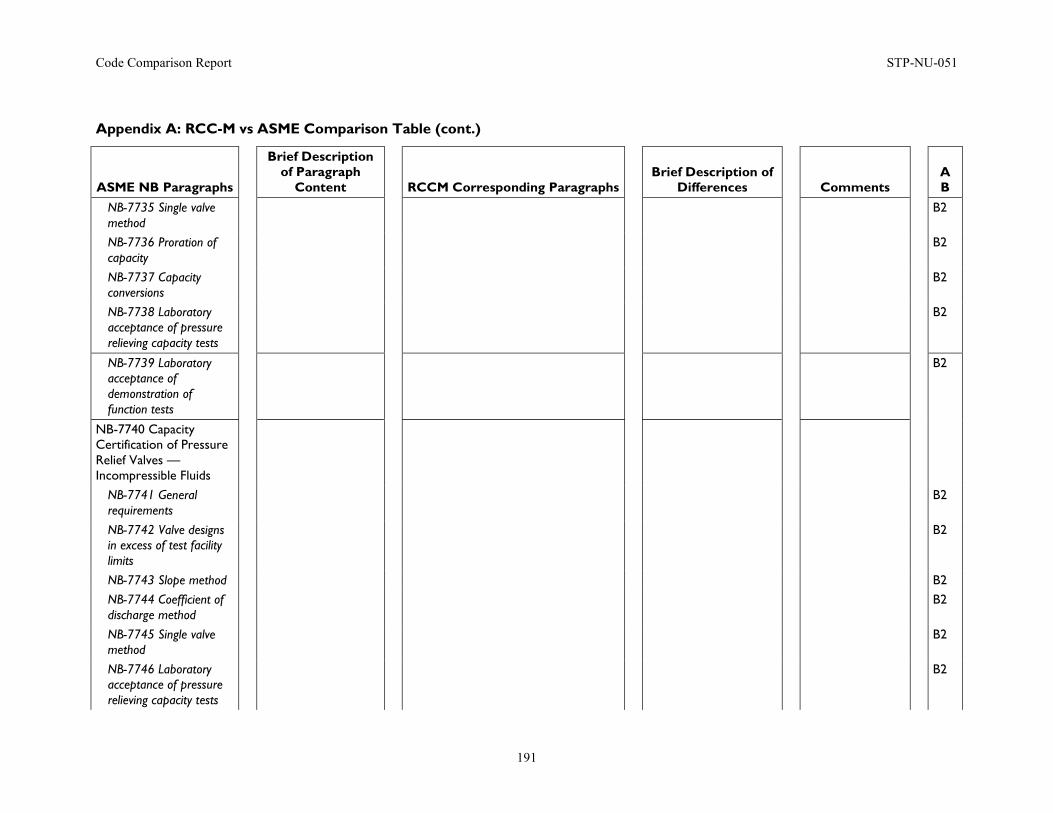
Code Comparison Report STP-NU-051
191
Appendix A: RCC-M vs ASME Comparison Table (cont.)
ASME NB Paragraphs
Brief Description of Paragraph
Content
RCCM Corresponding Paragraphs
Brief Description of Differences
Comments
A B
NB-7735 Single valve method
B2
NB-7736 Proration of capacity
B2
NB-7737 Capacity conversions
B2
NB-7738 Laboratory acceptance of pressure relieving capacity tests
B2
NB-7739 Laboratory acceptance of demonstration of function tests
B2
NB-7740 Capacity Certification of Pressure Relief Valves — Incompressible Fluids
NB-7741 General requirements
B2
NB-7742 Valve designs in excess of test facility limits
B2
NB-7743 Slope method B2 NB-7744 Coefficient of discharge method
B2
NB-7745 Single valve method
B2
NB-7746 Laboratory acceptance of pressure relieving capacity tests
B2
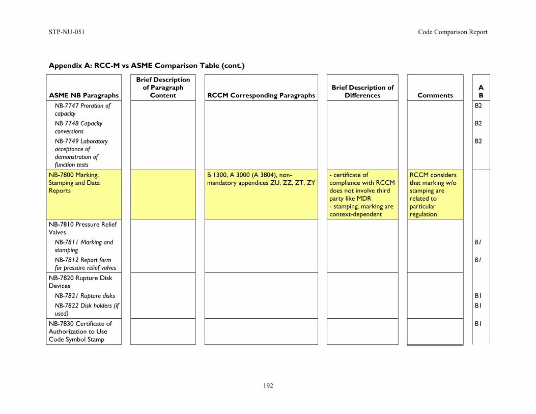
STP-NU-051 Code Comparison Report
192
Appendix A: RCC-M vs ASME Comparison Table (cont.)
ASME NB Paragraphs
Brief Description of Paragraph
Content
RCCM Corresponding Paragraphs
Brief Description of Differences
Comments
A B
NB-7747 Proration of capacity
B2
NB-7748 Capacity conversions
B2
NB-7749 Laboratory acceptance of demonstration of function tests
B2
NB-7800 Marking, Stamping and Data Reports
B 1300, A 3000 (A 3804), non- mandatory appendices ZU, ZZ, ZT, ZY
- certificate of compliance with RCCM does not involve third party like MDR - stamping, marking are context-dependent
RCCM considers that marking w/o stamping are related to particular regulation
NB-7810 Pressure Relief Valves
NB-7811 Marking and stamping
B1
NB-7812 Report form for pressure relief valves
B1
NB-7820 Rupture Disk Devices
NB-7821 Rupture disks B1 NB-7822 Disk holders (if used)
B1
NB-7830 Certificate of Authorization to Use Code Symbol Stamp
B1
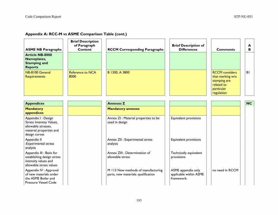
Code Comparison Report STP-NU-051
193
Appendix A: RCC-M vs ASME Comparison Table (cont.)
ASME NB Paragraphs
Brief Description of Paragraph
Content
RCCM Corresponding Paragraphs
Brief Description of Differences
Comments
A B
Article NB-8000 Nameplates, Stamping and Reports
NB-8100 General Requirements
Reference to NCA 8000
B 1300, A 3800 RCCM considers that marking w/o stamping are related to particular regulation
B1
Appendices Annexes Z NC Mandatory appendices
Mandatory annexes
Appendix I : Design Stress Intensity Values, allowable stresses, material properties and design curves
Annex ZI : Material properties to be used in design
Equivalent provisions
Appendix II :Experimental stress analysis
Annex ZII : Experimental stress analysis
Equivalent provisions
Appendix III : Basis for establishing design stress intensity values and allowable stress values
Annex ZIII : Determination of allowable stress
Technically equivalent provisions
Appendix IV : Approval of new materials under the ASME Boiler and Pressure Vessel Code
M 113 New methods of manufacturing parts, new materials: qualification
ASME appendix only applicable within ASME framework
no need in RCCM
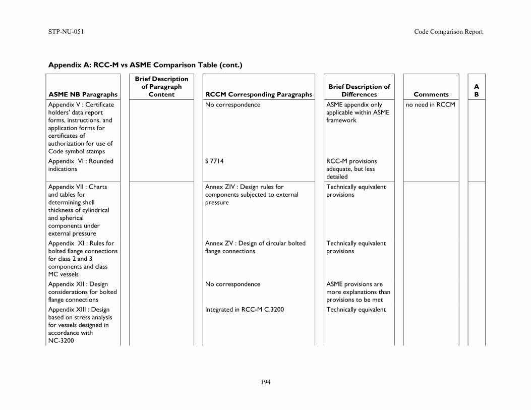
STP-NU-051 Code Comparison Report
194
Appendix A: RCC-M vs ASME Comparison Table (cont.)
ASME NB Paragraphs
Brief Description of Paragraph
Content
RCCM Corresponding Paragraphs
Brief Description of Differences
Comments
A B
Appendix V : Certificate holders' data report forms, instructions, and application forms for certificates of authorization for use of Code symbol stamps
No correspondence ASME appendix only applicable within ASME framework
no need in RCCM
Appendix VI : Rounded indications
S 7714 RCC-M provisions adequate, but less detailed
Appendix VII : Charts and tables for determining shell thickness of cylindrical and spherical components under external pressure
Annex ZIV : Design rules for components subjected to external pressure
Technically equivalent provisions
Appendix XI : Rules for bolted flange connections for class 2 and 3 components and class MC vessels
Annex ZV : Design of circular bolted flange connections
Technically equivalent provisions
Appendix XII : Design considerations for bolted flange connections
No correspondence ASME provisions are more explanations than provisions to be met
Appendix XIII : Design based on stress analysis for vessels designed in accordance with NC-3200
Integrated in RCC-M C.3200 Technically equivalent
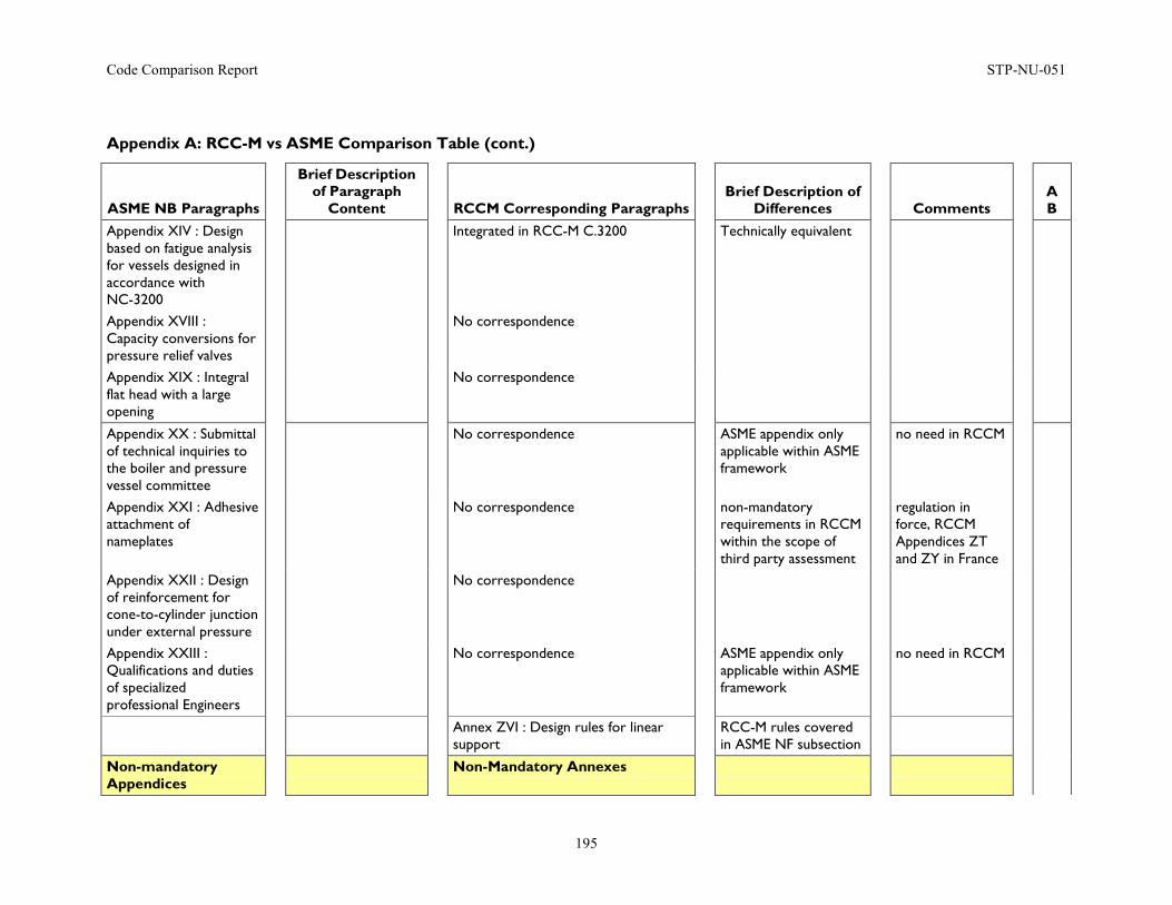
Code Comparison Report STP-NU-051
195
Appendix A: RCC-M vs ASME Comparison Table (cont.)
ASME NB Paragraphs
Brief Description of Paragraph
Content
RCCM Corresponding Paragraphs
Brief Description of Differences
Comments
A B
Appendix XIV : Design based on fatigue analysis for vessels designed in accordance with NC-3200
Integrated in RCC-M C.3200 Technically equivalent
Appendix XVIII : Capacity conversions for pressure relief valves
No correspondence
Appendix XIX : Integral flat head with a large opening
No correspondence
Appendix XX : Submittal of technical inquiries to the boiler and pressure vessel committee
No correspondence ASME appendix only applicable within ASME framework
no need in RCCM
Appendix XXI : Adhesive attachment of nameplates
No correspondence non-mandatory requirements in RCCM within the scope of third party assessment
regulation in force, RCCM Appendices ZT and ZY in France
Appendix XXII : Design of reinforcement for cone-to-cylinder junction under external pressure
No correspondence
Appendix XXIII : Qualifications and duties of specialized professional Engineers
No correspondence ASME appendix only applicable within ASME framework
no need in RCCM
Annex ZVI : Design rules for linear support
RCC-M rules covered in ASME NF subsection
Non-mandatory Appendices
Non-Mandatory Annexes
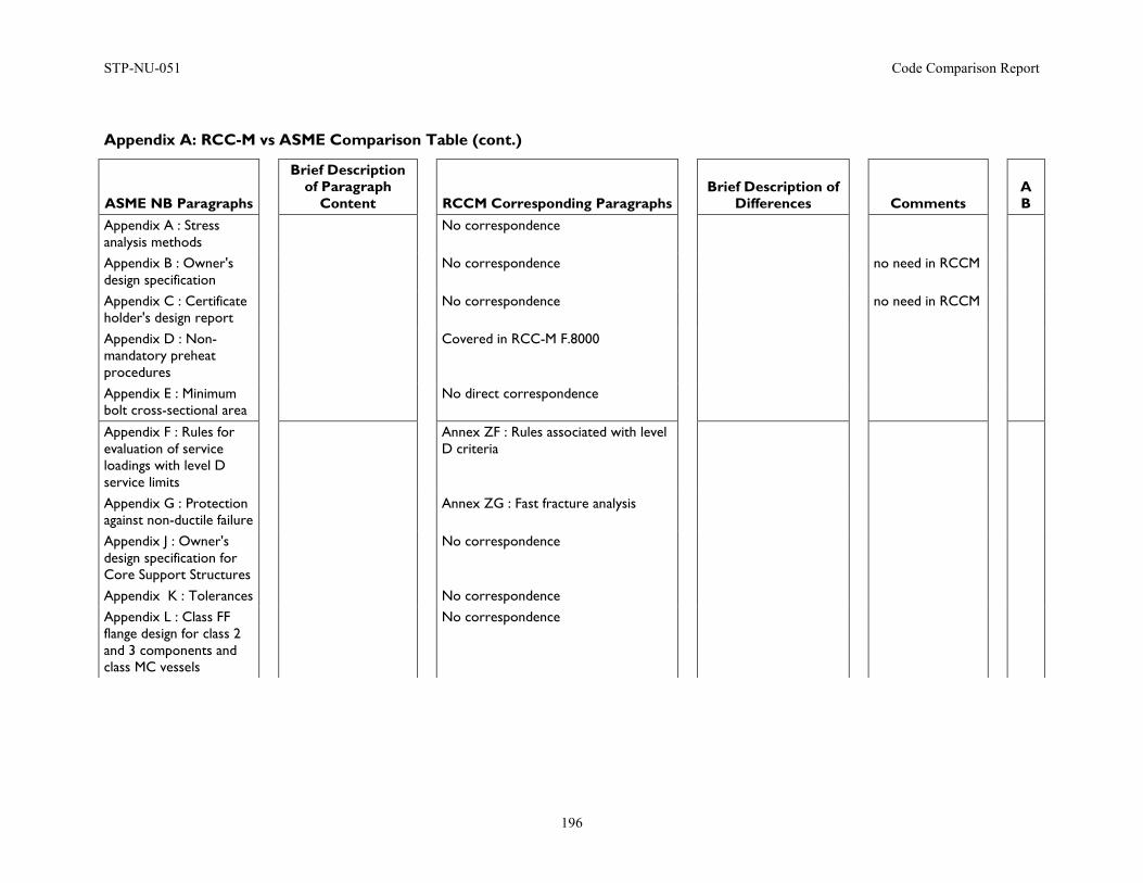
STP-NU-051 Code Comparison Report
196
Appendix A: RCC-M vs ASME Comparison Table (cont.)
ASME NB Paragraphs
Brief Description of Paragraph
Content
RCCM Corresponding Paragraphs
Brief Description of Differences
Comments
A B
Appendix A : Stress analysis methods
No correspondence
Appendix B : Owner's design specification
No correspondence no need in RCCM
Appendix C : Certificate holder's design report
No correspondence no need in RCCM
Appendix D : Non- mandatory preheat procedures
Covered in RCC-M F.8000
Appendix E : Minimum bolt cross-sectional area
No direct correspondence
Appendix F : Rules for evaluation of service loadings with level D service limits
Annex ZF : Rules associated with level D criteria
Appendix G : Protection against non-ductile failure
Annex ZG : Fast fracture analysis
Appendix J : Owner's design specification for Core Support Structures
No correspondence
Appendix K : Tolerances No correspondence
Appendix L : Class FF flange design for class 2 and 3 components and class MC vessels
No correspondence
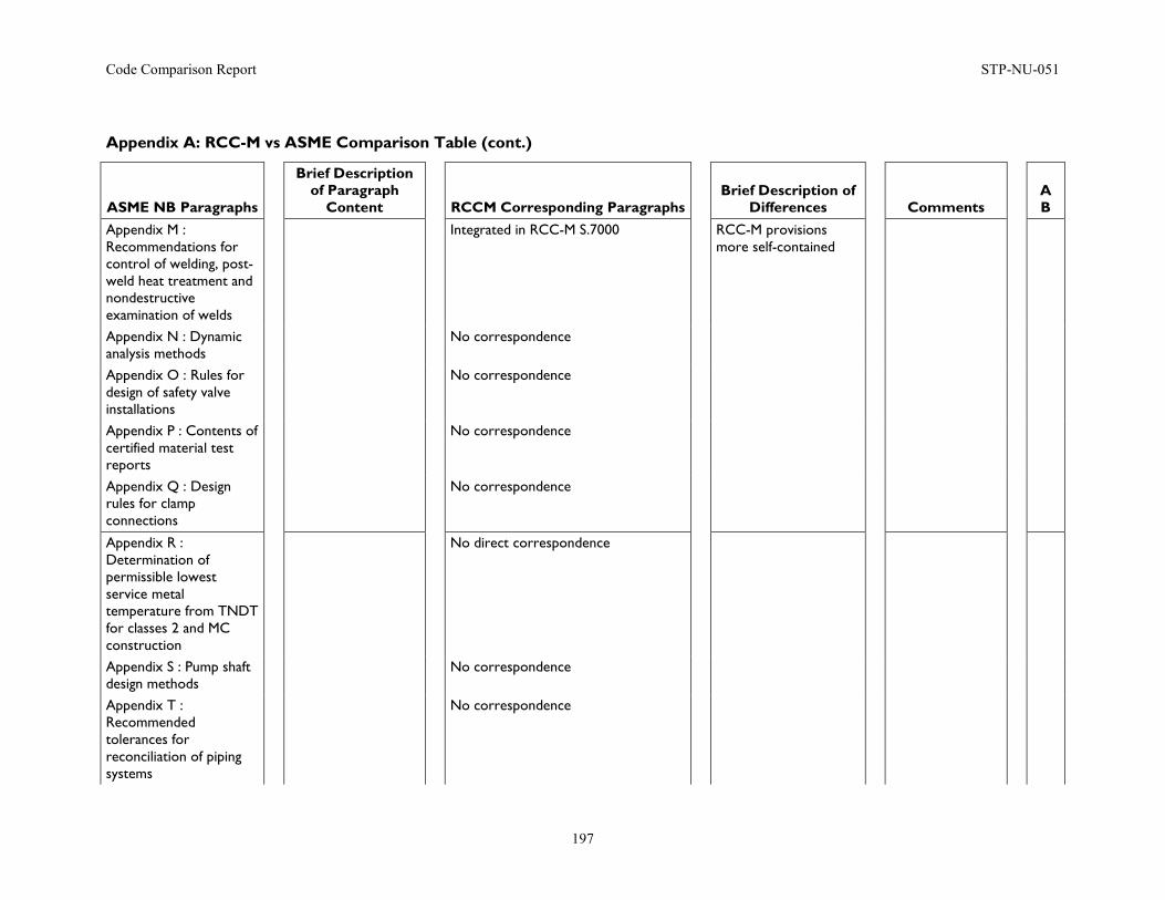
Code Comparison Report STP-NU-051
197
Appendix A: RCC-M vs ASME Comparison Table (cont.)
ASME NB Paragraphs
Brief Description of Paragraph
Content
RCCM Corresponding Paragraphs
Brief Description of Differences
Comments
A B
Appendix M : Recommendations for control of welding, post-weld heat treatment and nondestructive examination of welds
Integrated in RCC-M S.7000 RCC-M provisions more self-contained
Appendix N : Dynamic analysis methods
No correspondence
Appendix O : Rules for design of safety valve installations
No correspondence
Appendix P : Contents of certified material test reports
No correspondence
Appendix Q : Design rules for clamp connections
No correspondence
Appendix R : Determination of permissible lowest service metal temperature from TNDT for classes 2 and MC construction
No direct correspondence
Appendix S : Pump shaft design methods
No correspondence
Appendix T : Recommended tolerances for reconciliation of piping systems
No correspondence
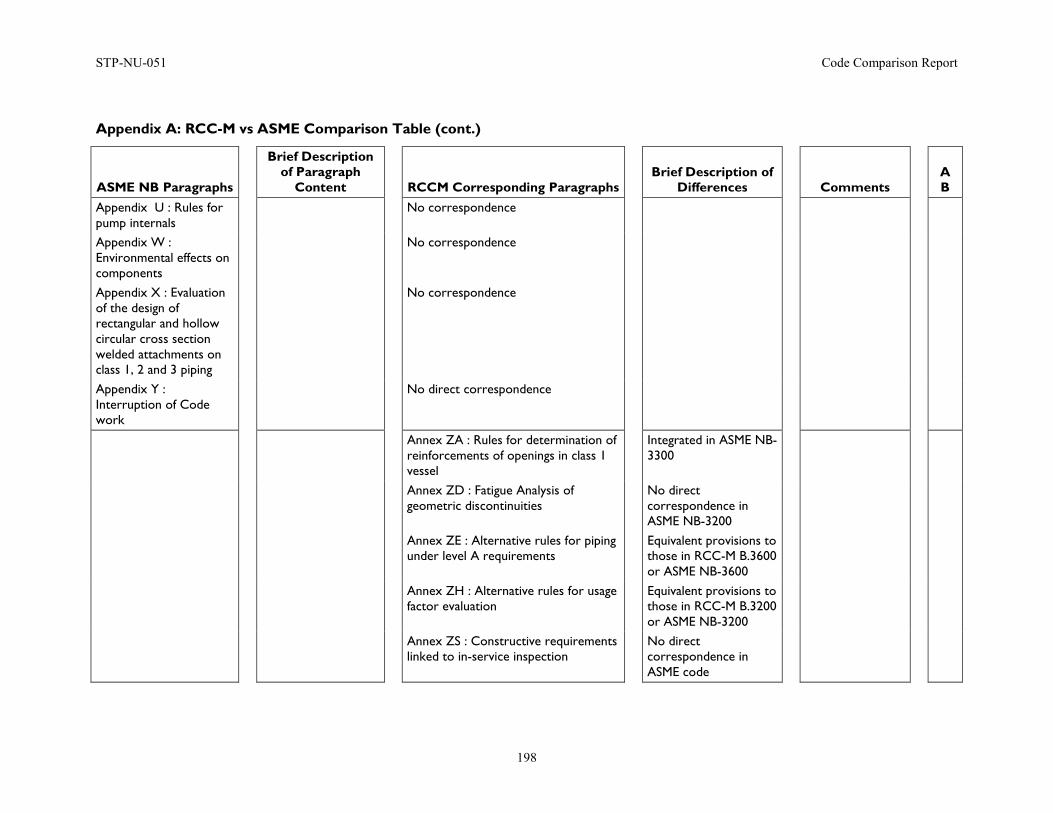
STP-NU-051 Code Comparison Report
198
Appendix A: RCC-M vs ASME Comparison Table (cont.)
ASME NB Paragraphs
Brief Description of Paragraph
Content
RCCM Corresponding Paragraphs
Brief Description of Differences
Comments
A B
Appendix U : Rules for pump internals
No correspondence
Appendix W : Environmental effects on components
No correspondence
Appendix X : Evaluation of the design of rectangular and hollow circular cross section welded attachments on class 1, 2 and 3 piping
No correspondence
Appendix Y : Interruption of Code work
No direct correspondence
Annex ZA : Rules for determination of reinforcements of openings in class 1 vessel
Integrated in ASME NB-3300
Annex ZD : Fatigue Analysis of geometric discontinuities
No direct correspondence in ASME NB-3200
Annex ZE : Alternative rules for piping under level A requirements
Equivalent provisions to those in RCC-M B.3600 or ASME NB-3600
Annex ZH : Alternative rules for usage factor evaluation
Equivalent provisions to those in RCC-M B.3200 or ASME NB-3200
Annex ZS : Constructive requirements linked to in-service inspection
No direct correspondence in ASME code
Code Comparison Report STP-NU-051
199
APPENDIX B: JSME VERSUS ASME SECTION III DETAILED COMPARISON TABLE
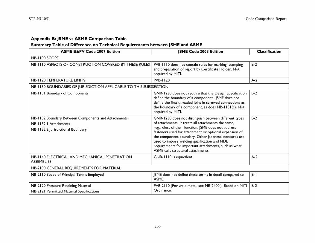
STP-NU-051 Code Comparison Report
200
Appendix B: JSME vs ASME Comparison Table Summary Table of Difference on Technical Requirements between JSME and ASME
ASME B&PV Code 2007 Edition JSME Code 2008 Edition Classification
NB-1100 SCOPE
NB-1110 ASPECTS OF CONSTRUCTION COVERED BY THESE RULES PVB-1110 does not contain rules for marking, stamping and preparation of report by Certificate Holder. Not required by MITI.
B-2
NB-1120 TEMPERATURE LIMITS PVB-1120 A-2
NB-1130 BOUNDARIES OF JURISDICTION APPLICABLE TO THIS SUBSSECTION
NB-1131 Boundary of Components GNR-1230 does not require that the Design Specification define the boundary of a component. JSME does not define the first threaded joint in screwed connections as the boundary of a component, as does NB-1131(c). Not required by MITI.
B-2
NB-1132.Boundary Between Components and Attachments NB-1132.1 Attachments NB-1132.2 Jurisdictional Boundary
GNR-1230 does not distinguish between different types of attachments. It treats all attachments the same, regardless of their function. JSME does not address fasteners used for attachment or optional expansion of the component boundary. Other Japanese standards are used to impose welding qualification and NDE requirements for important attachments, such as what ASME calls structural attachments.
B-2
NB-1140 ELECTRICAL AND MECHANICAL PENETRATION ASSEMBLIES
GNR-1110 is equivalent. A-2
NB-2100 GENERAL REQUIREMENTS FOR MATERIAL
NB-2110 Scope of Principal Terms Employed JSME does not define these terms in detail compared to ASME.
B-1
NB-2120 Pressure-Retaining Material NB-2121 Permitted Material Specifications
PVB-2110 (For weld metal, see NB-2400.) Based on MITI Ordinance.
B-2
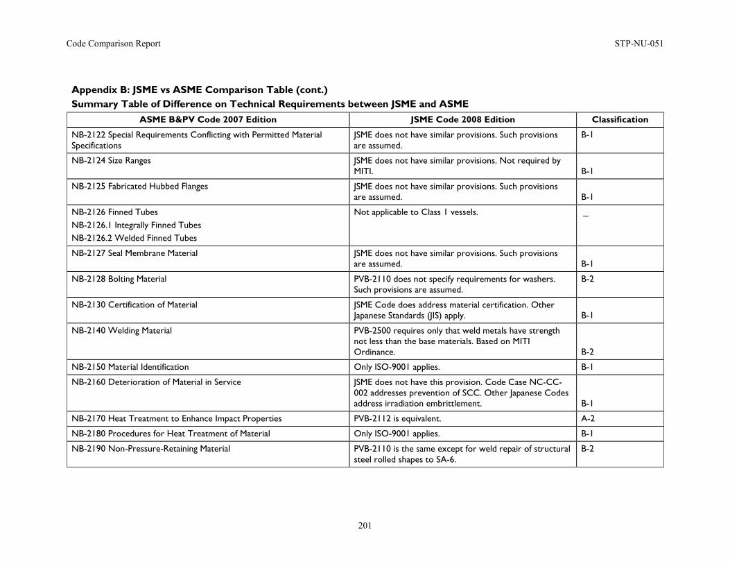
Code Comparison Report STP-NU-051
201
Appendix B: JSME vs ASME Comparison Table (cont.) Summary Table of Difference on Technical Requirements between JSME and ASME
ASME B&PV Code 2007 Edition JSME Code 2008 Edition Classification
NB-2122 Special Requirements Conflicting with Permitted Material Specifications
JSME does not have similar provisions. Such provisions are assumed.
B-1
NB-2124 Size Ranges JSME does not have similar provisions. Not required by MITI. B-1
NB-2125 Fabricated Hubbed Flanges JSME does not have similar provisions. Such provisions are assumed. B-1
NB-2126 Finned Tubes NB-2126.1 Integrally Finned Tubes NB-2126.2 Welded Finned Tubes
Not applicable to Class 1 vessels. -
NB-2127 Seal Membrane Material JSME does not have similar provisions. Such provisions are assumed. B-1
NB-2128 Bolting Material PVB-2110 does not specify requirements for washers. Such provisions are assumed.
B-2
NB-2130 Certification of Material JSME Code does address material certification. Other Japanese Standards (JIS) apply. B-1
NB-2140 Welding Material PVB-2500 requires only that weld metals have strength not less than the base materials. Based on MITI Ordinance. B-2
NB-2150 Material Identification Only ISO-9001 applies. B-1
NB-2160 Deterioration of Material in Service JSME does not have this provision. Code Case NC-CC-002 addresses prevention of SCC. Other Japanese Codes address irradiation embrittlement. B-1
NB-2170 Heat Treatment to Enhance Impact Properties PVB-2112 is equivalent. A-2
NB-2180 Procedures for Heat Treatment of Material Only ISO-9001 applies. B-1
NB-2190 Non-Pressure-Retaining Material PVB-2110 is the same except for weld repair of structural steel rolled shapes to SA-6.
B-2
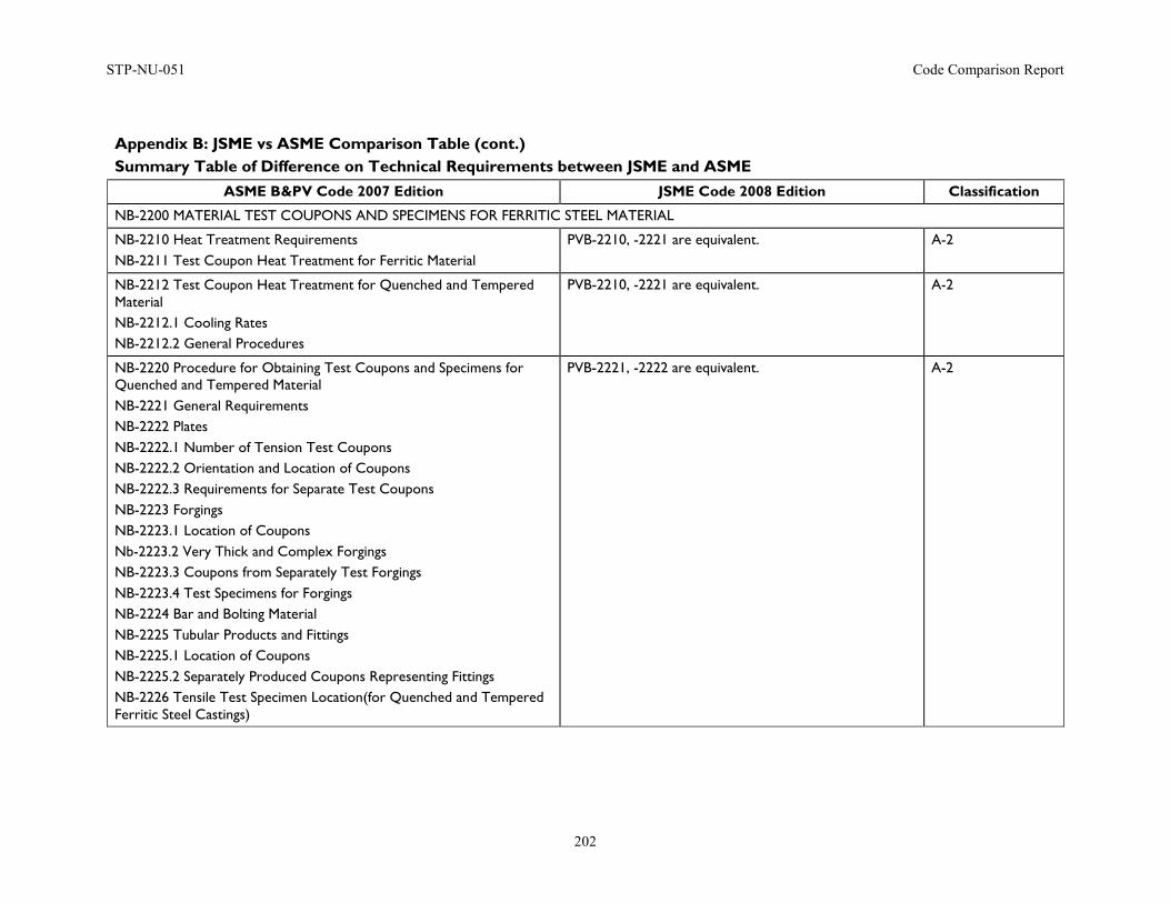
STP-NU-051 Code Comparison Report
202
Appendix B: JSME vs ASME Comparison Table (cont.) Summary Table of Difference on Technical Requirements between JSME and ASME
ASME B&PV Code 2007 Edition JSME Code 2008 Edition Classification
NB-2200 MATERIAL TEST COUPONS AND SPECIMENS FOR FERRITIC STEEL MATERIAL
NB-2210 Heat Treatment Requirements NB-2211 Test Coupon Heat Treatment for Ferritic Material
PVB-2210, -2221 are equivalent. A-2
NB-2212 Test Coupon Heat Treatment for Quenched and Tempered Material NB-2212.1 Cooling Rates NB-2212.2 General Procedures
PVB-2210, -2221 are equivalent. A-2
NB-2220 Procedure for Obtaining Test Coupons and Specimens for Quenched and Tempered Material NB-2221 General Requirements NB-2222 Plates NB-2222.1 Number of Tension Test Coupons NB-2222.2 Orientation and Location of Coupons NB-2222.3 Requirements for Separate Test Coupons NB-2223 Forgings NB-2223.1 Location of Coupons Nb-2223.2 Very Thick and Complex Forgings NB-2223.3 Coupons from Separately Test Forgings NB-2223.4 Test Specimens for Forgings NB-2224 Bar and Bolting Material NB-2225 Tubular Products and Fittings NB-2225.1 Location of Coupons NB-2225.2 Separately Produced Coupons Representing Fittings NB-2226 Tensile Test Specimen Location(for Quenched and Tempered Ferritic Steel Castings)
PVB-2221, -2222 are equivalent. A-2
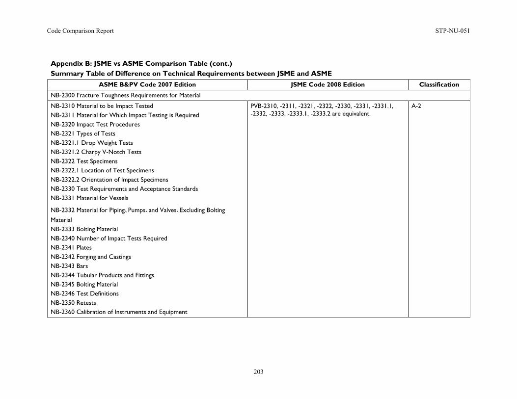
Code Comparison Report STP-NU-051
203
Appendix B: JSME vs ASME Comparison Table (cont.) Summary Table of Difference on Technical Requirements between JSME and ASME
ASME B&PV Code 2007 Edition JSME Code 2008 Edition Classification
NB-2300 Fracture Toughness Requirements for Material
NB-2310 Material to be Impact Tested NB-2311 Material for Which Impact Testing is Required NB-2320 Impact Test Procedures NB-2321 Types of Tests NB-2321.1 Drop Weight Tests NB-2321.2 Charpy V-Notch Tests NB-2322 Test Specimens NB-2322.1 Location of Test Specimens NB-2322.2 Orientation of Impact Specimens NB-2330 Test Requirements and Acceptance Standards NB-2331 Material for Vessels
NB-2332 Material for Piping、Pumps、and Valves、Excluding Bolting
Material NB-2333 Bolting Material NB-2340 Number of Impact Tests Required NB-2341 Plates NB-2342 Forging and Castings NB-2343 Bars NB-2344 Tubular Products and Fittings NB-2345 Bolting Material NB-2346 Test Definitions NB-2350 Retests NB-2360 Calibration of Instruments and Equipment
PVB-2310, -2311, -2321, -2322, -2330, -2331, -2331.1, -2332, -2333, -2333.1, -2333.2 are equivalent.
A-2
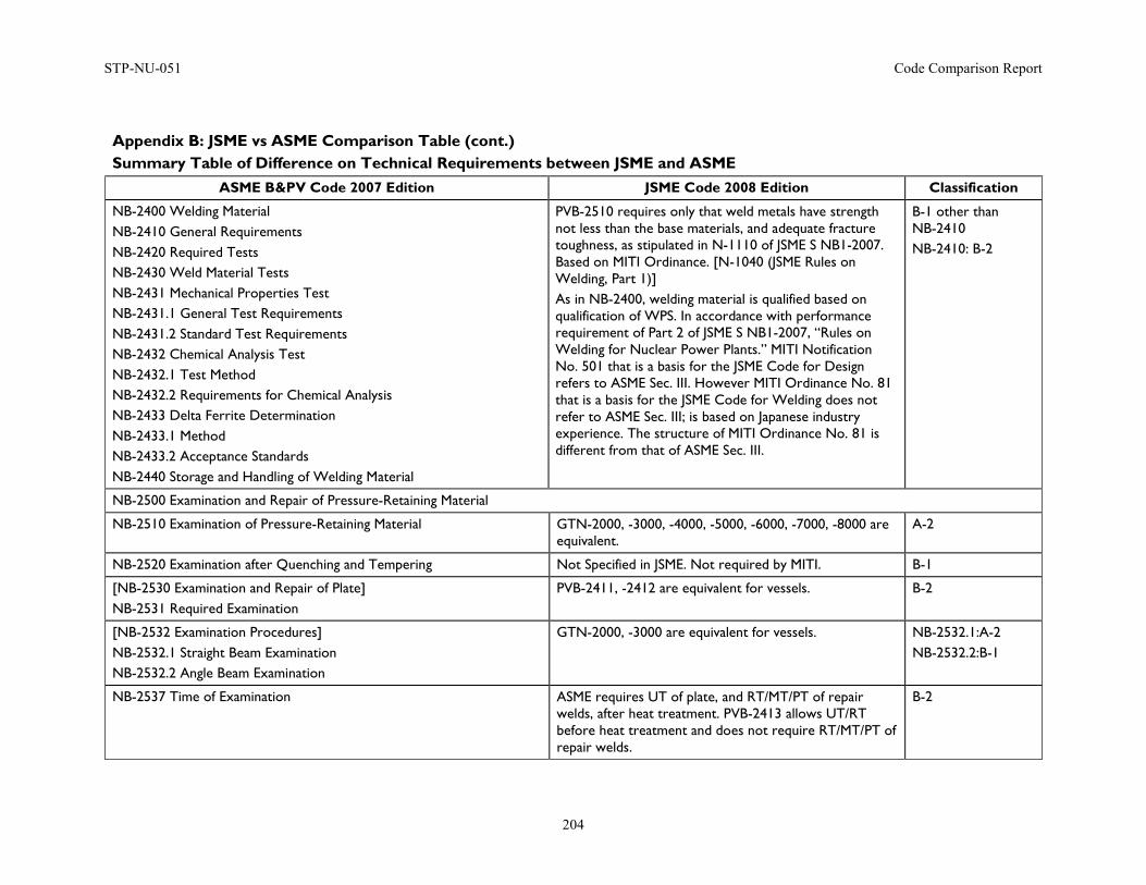
STP-NU-051 Code Comparison Report
204
Appendix B: JSME vs ASME Comparison Table (cont.) Summary Table of Difference on Technical Requirements between JSME and ASME
ASME B&PV Code 2007 Edition JSME Code 2008 Edition Classification
NB-2400 Welding Material NB-2410 General Requirements NB-2420 Required Tests NB-2430 Weld Material Tests NB-2431 Mechanical Properties Test NB-2431.1 General Test Requirements NB-2431.2 Standard Test Requirements NB-2432 Chemical Analysis Test NB-2432.1 Test Method NB-2432.2 Requirements for Chemical Analysis NB-2433 Delta Ferrite Determination NB-2433.1 Method NB-2433.2 Acceptance Standards NB-2440 Storage and Handling of Welding Material
PVB-2510 requires only that weld metals have strength not less than the base materials, and adequate fracture toughness, as stipulated in N-1110 of JSME S NB1-2007. Based on MITI Ordinance. [N-1040 (JSME Rules on Welding, Part 1)] As in NB-2400, welding material is qualified based on qualification of WPS. In accordance with performance requirement of Part 2 of JSME S NB1-2007, “Rules on Welding for Nuclear Power Plants.” MITI Notification No. 501 that is a basis for the JSME Code for Design refers to ASME Sec. III. However MITI Ordinance No. 81 that is a basis for the JSME Code for Welding does not refer to ASME Sec. III; is based on Japanese industry experience. The structure of MITI Ordinance No. 81 is different from that of ASME Sec. III.
B-1 other than NB-2410 NB-2410: B-2
NB-2500 Examination and Repair of Pressure-Retaining Material
NB-2510 Examination of Pressure-Retaining Material GTN-2000, -3000, -4000, -5000, -6000, -7000, -8000 are equivalent.
A-2
NB-2520 Examination after Quenching and Tempering Not Specified in JSME. Not required by MITI. B-1
[NB-2530 Examination and Repair of Plate] NB-2531 Required Examination
PVB-2411, -2412 are equivalent for vessels. B-2
[NB-2532 Examination Procedures] NB-2532.1 Straight Beam Examination NB-2532.2 Angle Beam Examination
GTN-2000, -3000 are equivalent for vessels. NB-2532.1:A-2 NB-2532.2:B-1
NB-2537 Time of Examination ASME requires UT of plate, and RT/MT/PT of repair welds, after heat treatment. PVB-2413 allows UT/RT before heat treatment and does not require RT/MT/PT of repair welds.
B-2
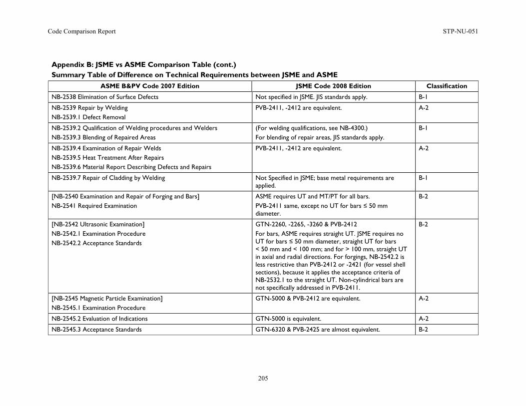
Code Comparison Report STP-NU-051
205
Appendix B: JSME vs ASME Comparison Table (cont.) Summary Table of Difference on Technical Requirements between JSME and ASME
ASME B&PV Code 2007 Edition JSME Code 2008 Edition Classification
NB-2538 Elimination of Surface Defects Not specified in JSME. JIS standards apply. B-1
NB-2539 Repair by Welding NB-2539.1 Defect Removal
PVB-2411, -2412 are equivalent. A-2
NB-2539.2 Qualification of Welding procedures and Welders NB-2539.3 Blending of Repaired Areas
(For welding qualifications, see NB-4300.) For blending of repair areas, JIS standards apply.
B-1
NB-2539.4 Examination of Repair Welds NB-2539.5 Heat Treatment After Repairs NB-2539.6 Material Report Describing Defects and Repairs
PVB-2411, -2412 are equivalent. A-2
NB-2539.7 Repair of Cladding by Welding Not Specified in JSME; base metal requirements are applied.
B-1
[NB-2540 Examination and Repair of Forging and Bars] NB-2541 Required Examination
ASME requires UT and MT/PT for all bars. PVB-2411 same, except no UT for bars ≤ 50 mm diameter.
B-2
[NB-2542 Ultrasonic Examination] NB-2542.1 Examination Procedure NB-2542.2 Acceptance Standards
GTN-2260, -2265, -3260 & PVB-2412 For bars, ASME requires straight UT. JSME requires no UT for bars ≤ 50 mm diameter, straight UT for bars < 50 mm and < 100 mm; and for > 100 mm, straight UT in axial and radial directions. For forgings, NB-2542.2 is less restrictive than PVB-2412 or -2421 (for vessel shell sections), because it applies the acceptance criteria of NB-2532.1 to the straight UT. Non-cylindrical bars are not specifically addressed in PVB-2411.
B-2
[NB-2545 Magnetic Particle Examination] NB-2545.1 Examination Procedure
GTN-5000 & PVB-2412 are equivalent. A-2
NB-2545.2 Evaluation of Indications GTN-5000 is equivalent. A-2
NB-2545.3 Acceptance Standards GTN-6320 & PVB-2425 are almost equivalent. B-2
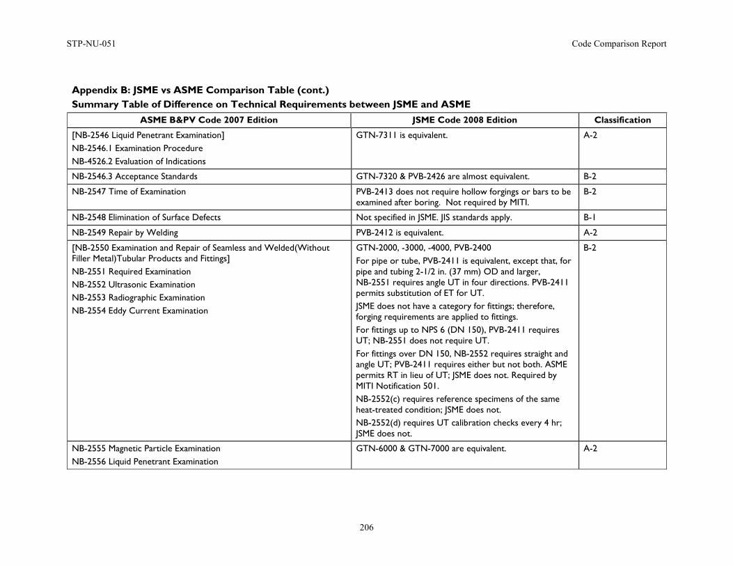
STP-NU-051 Code Comparison Report
206
Appendix B: JSME vs ASME Comparison Table (cont.) Summary Table of Difference on Technical Requirements between JSME and ASME
ASME B&PV Code 2007 Edition JSME Code 2008 Edition Classification
[NB-2546 Liquid Penetrant Examination] NB-2546.1 Examination Procedure NB-4526.2 Evaluation of Indications
GTN-7311 is equivalent. A-2
NB-2546.3 Acceptance Standards GTN-7320 & PVB-2426 are almost equivalent. B-2
NB-2547 Time of Examination PVB-2413 does not require hollow forgings or bars to be examined after boring. Not required by MITI.
B-2
NB-2548 Elimination of Surface Defects Not specified in JSME. JIS standards apply. B-1
NB-2549 Repair by Welding PVB-2412 is equivalent. A-2
[NB-2550 Examination and Repair of Seamless and Welded(Without Filler Metal)Tubular Products and Fittings] NB-2551 Required Examination NB-2552 Ultrasonic Examination NB-2553 Radiographic Examination NB-2554 Eddy Current Examination
GTN-2000, -3000, -4000, PVB-2400 For pipe or tube, PVB-2411 is equivalent, except that, for pipe and tubing 2-1/2 in. (37 mm) OD and larger, NB-2551 requires angle UT in four directions. PVB-2411 permits substitution of ET for UT. JSME does not have a category for fittings; therefore, forging requirements are applied to fittings. For fittings up to NPS 6 (DN 150), PVB-2411 requires UT; NB-2551 does not require UT. For fittings over DN 150, NB-2552 requires straight and angle UT; PVB-2411 requires either but not both. ASME permits RT in lieu of UT; JSME does not. Required by MITI Notification 501. NB-2552(c) requires reference specimens of the same heat-treated condition; JSME does not. NB-2552(d) requires UT calibration checks every 4 hr; JSME does not.
B-2
NB-2555 Magnetic Particle Examination NB-2556 Liquid Penetrant Examination
GTN-6000 & GTN-7000 are equivalent. A-2
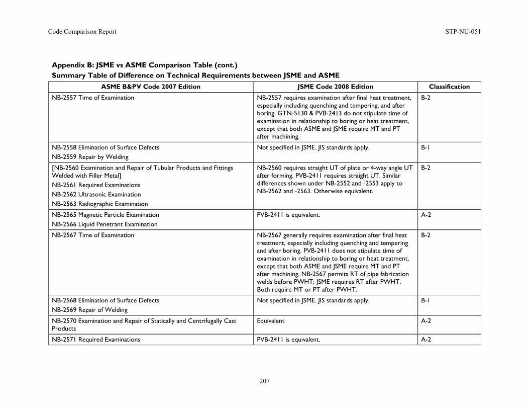
Code Comparison Report STP-NU-051
207
Appendix B: JSME vs ASME Comparison Table (cont.) Summary Table of Difference on Technical Requirements between JSME and ASME
ASME B&PV Code 2007 Edition JSME Code 2008 Edition Classification
NB-2557 Time of Examination NB-2557 requires examination after final heat treatment, especially including quenching and tempering, and after boring. GTN-5130 & PVB-2413 do not stipulate time of examination in relationship to boring or heat treatment, except that both ASME and JSME require MT and PT after machining.
B-2
NB-2558 Elimination of Surface Defects NB-2559 Repair by Welding
Not specified in JSME. JIS standards apply. B-1
[NB-2560 Examination and Repair of Tubular Products and Fittings Welded with Filler Metal] NB-2561 Required Examinations NB-2562 Ultrasonic Examination NB-2563 Radiographic Examination
NB-2560 requires straight UT of plate or 4-way angle UT after forming. PVB-2411 requires straight UT. Similar differences shown under NB-2552 and -2553 apply to NB-2562 and -2563. Otherwise equivalent.
B-2
NB-2565 Magnetic Particle Examination NB-2566 Liquid Penetrant Examination
PVB-2411 is equivalent. A-2
NB-2567 Time of Examination NB-2567 generally requires examination after final heat treatment, especially including quenching and tempering and after boring. PVB-2411 does not stipulate time of examination in relationship to boring or heat treatment, except that both ASME and JSME require MT and PT after machining. NB-2567 permits RT of pipe fabrication welds before PWHT; JSME requires RT after PWHT. Both require MT or PT after PWHT.
B-2
NB-2568 Elimination of Surface Defects NB-2569 Repair of Welding
Not specified in JSME. JIS standards apply. B-1
NB-2570 Examination and Repair of Statically and Centrifugally Cast Products
Equivalent A-2
NB-2571 Required Examinations PVB-2411 is equivalent. A-2
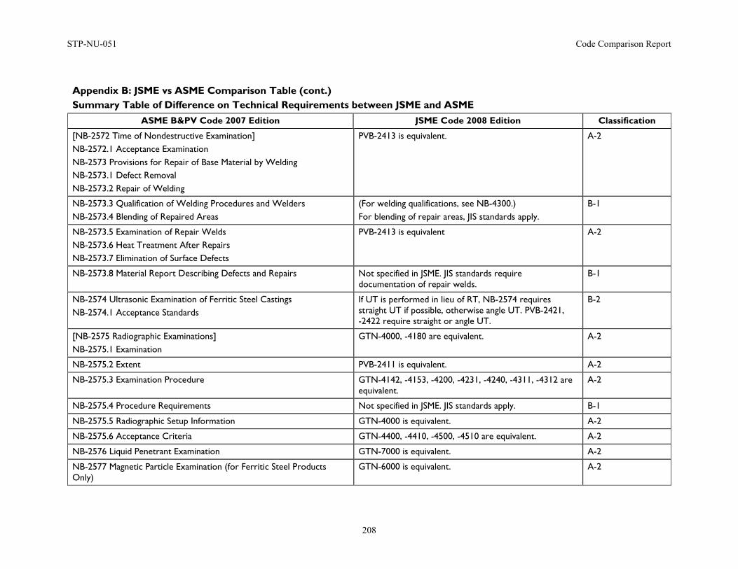
STP-NU-051 Code Comparison Report
208
Appendix B: JSME vs ASME Comparison Table (cont.) Summary Table of Difference on Technical Requirements between JSME and ASME
ASME B&PV Code 2007 Edition JSME Code 2008 Edition Classification
[NB-2572 Time of Nondestructive Examination] NB-2572.1 Acceptance Examination NB-2573 Provisions for Repair of Base Material by Welding NB-2573.1 Defect Removal NB-2573.2 Repair of Welding
PVB-2413 is equivalent. A-2
NB-2573.3 Qualification of Welding Procedures and Welders NB-2573.4 Blending of Repaired Areas
(For welding qualifications, see NB-4300.) For blending of repair areas, JIS standards apply.
B-1
NB-2573.5 Examination of Repair Welds NB-2573.6 Heat Treatment After Repairs NB-2573.7 Elimination of Surface Defects
PVB-2413 is equivalent A-2
NB-2573.8 Material Report Describing Defects and Repairs Not specified in JSME. JIS standards require documentation of repair welds.
B-1
NB-2574 Ultrasonic Examination of Ferritic Steel Castings NB-2574.1 Acceptance Standards
If UT is performed in lieu of RT, NB-2574 requires straight UT if possible, otherwise angle UT. PVB-2421, -2422 require straight or angle UT.
B-2
[NB-2575 Radiographic Examinations] NB-2575.1 Examination
GTN-4000, -4180 are equivalent. A-2
NB-2575.2 Extent PVB-2411 is equivalent. A-2
NB-2575.3 Examination Procedure GTN-4142, -4153, -4200, -4231, -4240, -4311, -4312 are equivalent.
A-2
NB-2575.4 Procedure Requirements Not specified in JSME. JIS standards apply. B-1
NB-2575.5 Radiographic Setup Information GTN-4000 is equivalent. A-2
NB-2575.6 Acceptance Criteria GTN-4400, -4410, -4500, -4510 are equivalent. A-2
NB-2576 Liquid Penetrant Examination GTN-7000 is equivalent. A-2
NB-2577 Magnetic Particle Examination (for Ferritic Steel Products Only)
GTN-6000 is equivalent. A-2
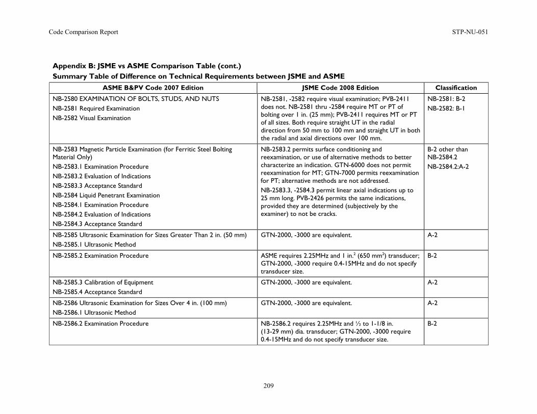
Code Comparison Report STP-NU-051
209
Appendix B: JSME vs ASME Comparison Table (cont.) Summary Table of Difference on Technical Requirements between JSME and ASME
ASME B&PV Code 2007 Edition JSME Code 2008 Edition Classification
NB-2580 EXAMINATION OF BOLTS, STUDS, AND NUTS NB-2581 Required Examination NB-2582 Visual Examination
NB-2581, -2582 require visual examination; PVB-2411 does not. NB-2581 thru -2584 require MT or PT of bolting over 1 in. (25 mm); PVB-2411 requires MT or PT of all sizes. Both require straight UT in the radial direction from 50 mm to 100 mm and straight UT in both the radial and axial directions over 100 mm.
NB-2581: B-2 NB-2582: B-1
NB-2583 Magnetic Particle Examination (for Ferritic Steel Bolting Material Only) NB-2583.1 Examination Procedure NB-2583.2 Evaluation of Indications NB-2583.3 Acceptance Standard NB-2584 Liquid Penetrant Examination NB-2584.1 Examination Procedure NB-2584.2 Evaluation of Indications NB-2584.3 Acceptance Standard
NB-2583.2 permits surface conditioning and reexamination, or use of alternative methods to better characterize an indication. GTN-6000 does not permit reexamination for MT; GTN-7000 permits reexamination for PT; alternative methods are not addressed. NB-2583.3, -2584.3 permit linear axial indications up to 25 mm long. PVB-2426 permits the same indications, provided they are determined (subjectively by the examiner) to not be cracks.
B-2 other than NB-2584.2 NB-2584.2:A-2
NB-2585 Ultrasonic Examination for Sizes Greater Than 2 in. (50 mm) NB-2585.1 Ultrasonic Method
GTN-2000, -3000 are equivalent. A-2
NB-2585.2 Examination Procedure ASME requires 2.25MHz and 1 in.2 (650 mm2) transducer; GTN-2000, -3000 require 0.4-15MHz and do not specify transducer size.
B-2
NB-2585.3 Calibration of Equipment NB-2585.4 Acceptance Standard
GTN-2000, -3000 are equivalent. A-2
NB-2586 Ultrasonic Examination for Sizes Over 4 in. (100 mm) NB-2586.1 Ultrasonic Method
GTN-2000, -3000 are equivalent. A-2
NB-2586.2 Examination Procedure NB-2586.2 requires 2.25MHz and ½ to 1-1/8 in. (13-29 mm) dia. transducer; GTN-2000, -3000 require 0.4-15MHz and do not specify transducer size.
B-2
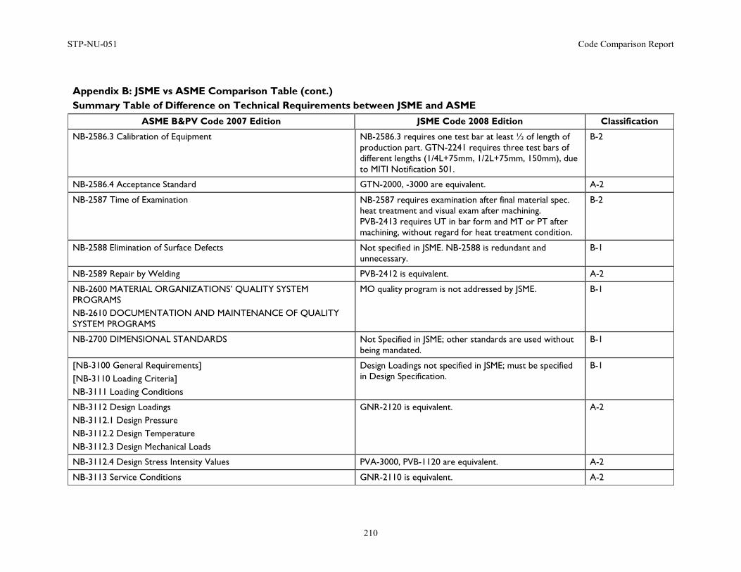
STP-NU-051 Code Comparison Report
210
Appendix B: JSME vs ASME Comparison Table (cont.) Summary Table of Difference on Technical Requirements between JSME and ASME
ASME B&PV Code 2007 Edition JSME Code 2008 Edition Classification
NB-2586.3 Calibration of Equipment NB-2586.3 requires one test bar at least ½ of length of production part. GTN-2241 requires three test bars of different lengths (1/4L+75mm, 1/2L+75mm, 150mm), due to MITI Notification 501.
B-2
NB-2586.4 Acceptance Standard GTN-2000, -3000 are equivalent. A-2
NB-2587 Time of Examination NB-2587 requires examination after final material spec. heat treatment and visual exam after machining. PVB-2413 requires UT in bar form and MT or PT after machining, without regard for heat treatment condition.
B-2
NB-2588 Elimination of Surface Defects Not specified in JSME. NB-2588 is redundant and unnecessary.
B-1
NB-2589 Repair by Welding PVB-2412 is equivalent. A-2
NB-2600 MATERIAL ORGANIZATIONS’ QUALITY SYSTEM PROGRAMS NB-2610 DOCUMENTATION AND MAINTENANCE OF QUALITY SYSTEM PROGRAMS
MO quality program is not addressed by JSME. B-1
NB-2700 DIMENSIONAL STANDARDS Not Specified in JSME; other standards are used without being mandated.
B-1
[NB-3100 General Requirements] [NB-3110 Loading Criteria] NB-3111 Loading Conditions
Design Loadings not specified in JSME; must be specified in Design Specification.
B-1
NB-3112 Design Loadings NB-3112.1 Design Pressure NB-3112.2 Design Temperature NB-3112.3 Design Mechanical Loads
GNR-2120 is equivalent. A-2
NB-3112.4 Design Stress Intensity Values PVA-3000, PVB-1120 are equivalent. A-2
NB-3113 Service Conditions GNR-2110 is equivalent. A-2
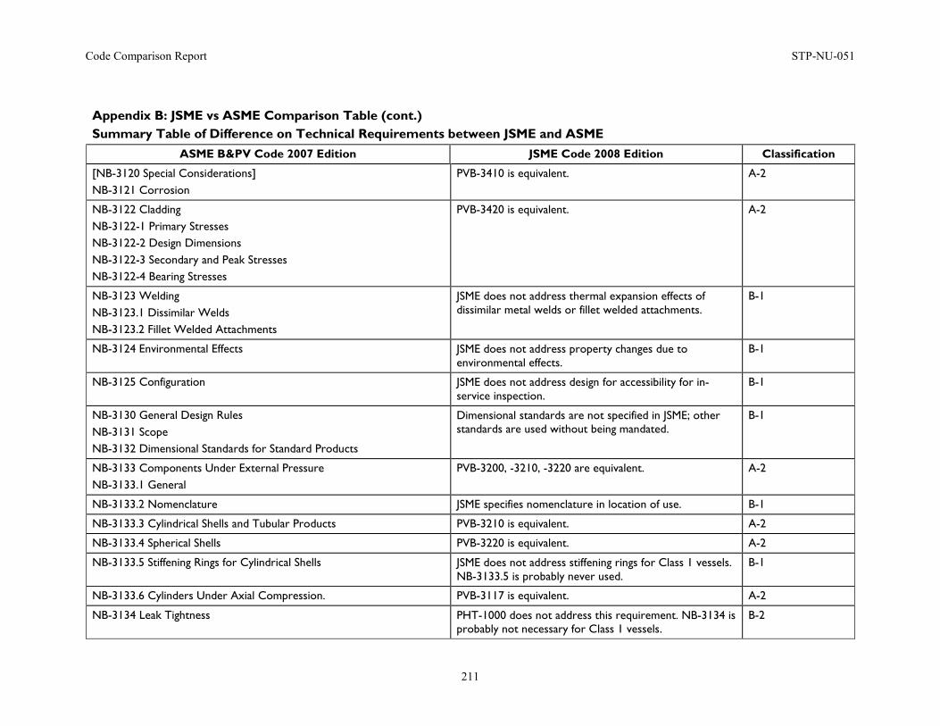
Code Comparison Report STP-NU-051
211
Appendix B: JSME vs ASME Comparison Table (cont.) Summary Table of Difference on Technical Requirements between JSME and ASME
ASME B&PV Code 2007 Edition JSME Code 2008 Edition Classification
[NB-3120 Special Considerations] NB-3121 Corrosion
PVB-3410 is equivalent. A-2
NB-3122 Cladding NB-3122-1 Primary Stresses NB-3122-2 Design Dimensions NB-3122-3 Secondary and Peak Stresses NB-3122-4 Bearing Stresses
PVB-3420 is equivalent. A-2
NB-3123 Welding NB-3123.1 Dissimilar Welds NB-3123.2 Fillet Welded Attachments
JSME does not address thermal expansion effects of dissimilar metal welds or fillet welded attachments.
B-1
NB-3124 Environmental Effects JSME does not address property changes due to environmental effects.
B-1
NB-3125 Configuration JSME does not address design for accessibility for in-service inspection.
B-1
NB-3130 General Design Rules NB-3131 Scope NB-3132 Dimensional Standards for Standard Products
Dimensional standards are not specified in JSME; other standards are used without being mandated.
B-1
NB-3133 Components Under External Pressure NB-3133.1 General
PVB-3200, -3210, -3220 are equivalent. A-2
NB-3133.2 Nomenclature JSME specifies nomenclature in location of use. B-1
NB-3133.3 Cylindrical Shells and Tubular Products PVB-3210 is equivalent. A-2
NB-3133.4 Spherical Shells PVB-3220 is equivalent. A-2
NB-3133.5 Stiffening Rings for Cylindrical Shells JSME does not address stiffening rings for Class 1 vessels. NB-3133.5 is probably never used.
B-1
NB-3133.6 Cylinders Under Axial Compression. PVB-3117 is equivalent. A-2
NB-3134 Leak Tightness PHT-1000 does not address this requirement. NB-3134 is probably not necessary for Class 1 vessels.
B-2
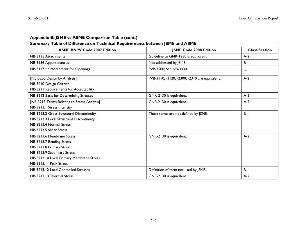
STP-NU-051 Code Comparison Report
212
Appendix B: JSME vs ASME Comparison Table (cont.) Summary Table of Difference on Technical Requirements between JSME and ASME
ASME B&PV Code 2007 Edition JSME Code 2008 Edition Classification
NB-3135 Attachments Guideline to GNR-1230 is equivalent. A-2
NB-3136 Appurtenances Not addressed by JSME. B-1
NB-3137 Reinforcement for Openings PVB-3500; See NB-3330. -
[NB-3200 Design by Analysis] NB-3210 Design Criteria NB-3211 Requirements for Acceptability
PVB-3110, -3120, -2300, -2310 are equivalent. A-2
NB-3212 Basis for Determining Stresses GNR-2130 is equivalent. A-2
[NB-3213 Terms Relating to Stress Analysis] NB-3213.1 Stress Intensity
GNR-2130 is equivalent. A-2
NB-3213.2 Gross Structural Discontinuity NB-3213.3 Local Structural Discontinuity NB-3213.4 Normal Stress NB-3213.5 Shear Stress
These terms are not defined by JSME. B-1
NB-3213.6 Membrane Stress NB-3213.7 Bending Stress NB-3213.8 Primary Stress NB-3213.9 Secondary Stress NB-3213.10 Local Primary Membrane Stress NB-3213.11 Peak Stress
GNR-2130 is equivalent. A-2
NB-3213.12 Load Controlled Stresses Definition of term not used by JSME. B-1
NB-3213.13 Thermal Stress GNR-2130 is equivalent. A-2
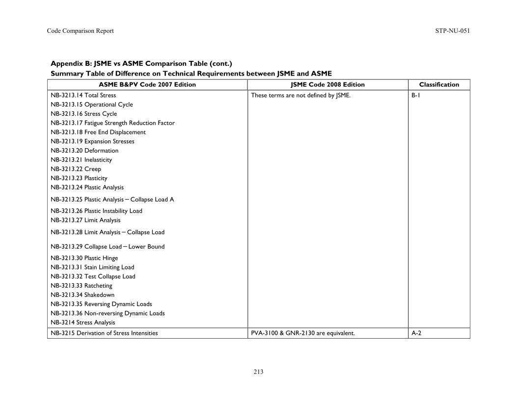
Code Comparison Report STP-NU-051
213
Appendix B: JSME vs ASME Comparison Table (cont.) Summary Table of Difference on Technical Requirements between JSME and ASME
ASME B&PV Code 2007 Edition JSME Code 2008 Edition Classification
NB-3213.14 Total Stress NB-3213.15 Operational Cycle NB-3213.16 Stress Cycle NB-3213.17 Fatigue Strength Reduction Factor NB-3213.18 Free End Displacement NB-3213.19 Expansion Stresses NB-3213.20 Deformation NB-3213.21 Inelasticity NB-3213.22 Creep NB-3213.23 Plasticity NB-3213.24 Plastic Analysis
NB-3213.25 Plastic Analysis-Collapse Load A
NB-3213.26 Plastic Instability Load NB-3213.27 Limit Analysis
NB-3213.28 Limit Analysis-Collapse Load
NB-3213.29 Collapse Load-Lower Bound
NB-3213.30 Plastic Hinge NB-3213.31 Stain Limiting Load NB-3213.32 Test Collapse Load NB-3213.33 Ratcheting NB-3213.34 Shakedown NB-3213.35 Reversing Dynamic Loads NB-3213.36 Non-reversing Dynamic Loads NB-3214 Stress Analysis
These terms are not defined by JSME. B-1
NB-3215 Derivation of Stress Intensities PVA-3100 & GNR-2130 are equivalent. A-2
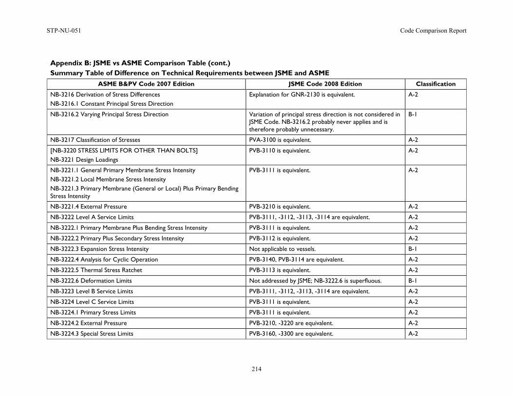
STP-NU-051 Code Comparison Report
214
Appendix B: JSME vs ASME Comparison Table (cont.) Summary Table of Difference on Technical Requirements between JSME and ASME
ASME B&PV Code 2007 Edition JSME Code 2008 Edition Classification
NB-3216 Derivation of Stress Differences NB-3216.1 Constant Principal Stress Direction
Explanation for GNR-2130 is equivalent. A-2
NB-3216.2 Varying Principal Stress Direction Variation of principal stress direction is not considered in JSME Code. NB-3216.2 probably never applies and is therefore probably unnecessary.
B-1
NB-3217 Classification of Stresses PVA-3100 is equivalent. A-2
[NB-3220 STRESS LIMITS FOR OTHER THAN BOLTS] NB-3221 Design Loadings
PVB-3110 is equivalent. A-2
NB-3221.1 General Primary Membrane Stress Intensity NB-3221.2 Local Membrane Stress Intensity NB-3221.3 Primary Membrane (General or Local) Plus Primary Bending Stress Intensity
PVB-3111 is equivalent. A-2
NB-3221.4 External Pressure PVB-3210 is equivalent. A-2
NB-3222 Level A Service Limits PVB-3111, -3112, -3113, -3114 are equivalent. A-2
NB-3222.1 Primary Membrane Plus Bending Stress Intensity PVB-3111 is equivalent. A-2
NB-3222.2 Primary Plus Secondary Stress Intensity PVB-3112 is equivalent. A-2
NB-3222.3 Expansion Stress Intensity Not applicable to vessels. B-1
NB-3222.4 Analysis for Cyclic Operation PVB-3140, PVB-3114 are equivalent. A-2
NB-3222.5 Thermal Stress Ratchet PVB-3113 is equivalent. A-2
NB-3222.6 Deformation Limits Not addressed by JSME; NB-3222.6 is superfluous. B-1
NB-3223 Level B Service Limits PVB-3111, -3112, -3113, -3114 are equivalent. A-2
NB-3224 Level C Service Limits PVB-3111 is equivalent. A-2
NB-3224.1 Primary Stress Limits PVB-3111 is equivalent. A-2
NB-3224.2 External Pressure PVB-3210, -3220 are equivalent. A-2
NB-3224.3 Special Stress Limits PVB-3160, -3300 are equivalent. A-2
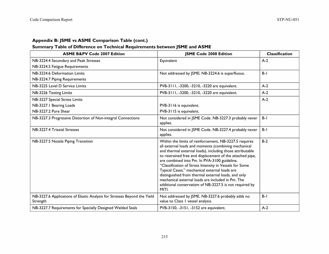
Code Comparison Report STP-NU-051
215
Appendix B: JSME vs ASME Comparison Table (cont.) Summary Table of Difference on Technical Requirements between JSME and ASME
ASME B&PV Code 2007 Edition JSME Code 2008 Edition Classification
NB-3224.4 Secondary and Peak Stresses NB-3224.5 Fatigue Requirements
Equivalent A-2
NB-3224.6 Deformation Limits NB-3224.7 Piping Requirements
Not addressed by JSME; NB-3224.6 is superfluous. B-1
NB-3225 Level D Service Limits PVB-3111, -3200, -3210, -3220 are equivalent. A-2
NB-3226 Testing Limits PVB-3111, -3200, -3210, -3220 are equivalent. A-2
NB-3227 Special Stress Limits NB-3227.1 Bearing Loads NB-3227.2 Pure Shear
PVB-3116 is equivalent. PVB-3115 is equivalent.
A-2
NB-3227.3 Progressive Distortion of Non-integral Connections Not considered in JSME Code. NB-3227.3 probably never applies.
B-1
NB-3227.4 Triaxial Stresses Not considered in JSME Code. NB-3227.4 probably never applies.
B-1
NB-3227.5 Nozzle Piping Transition Within the limits of reinforcement, NB-3227.5 requires all external loads and moments (combining mechanical and thermal external loads), including those attributable to restrained free end displacement of the attached pipe, are combined into Pm. In PVA-3100 guideline, “Classification of Stress Intensity in Vessels for Some Typical Cases,” mechanical external loads are distinguished from thermal external loads, and only mechanical external loads are included in Pm. The additional conservatism of NB-3227.5 is not required by MITI.
B-2
NB-3227.6 Applications of Elastic Analysis for Stresses Beyond the Yield Strength
Not addressed by JSME. NB-3227.6 probably adds no value to Class 1 vessel analysis.
B-1
NB-3227.7 Requirements for Specially Designed Welded Seals PVB-3150, -3151, -3152 are equivalent. A-2
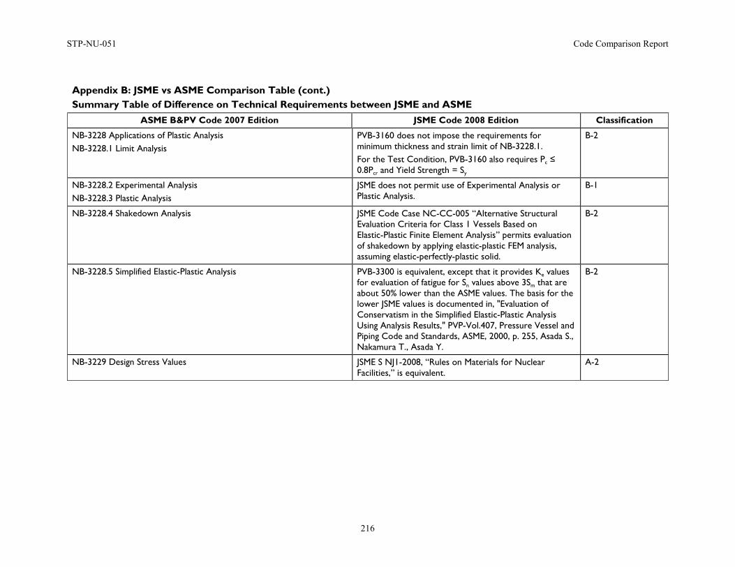
STP-NU-051 Code Comparison Report
216
Appendix B: JSME vs ASME Comparison Table (cont.) Summary Table of Difference on Technical Requirements between JSME and ASME
ASME B&PV Code 2007 Edition JSME Code 2008 Edition Classification
NB-3228 Applications of Plastic Analysis NB-3228.1 Limit Analysis
PVB-3160 does not impose the requirements for minimum thickness and strain limit of NB-3228.1. For the Test Condition, PVB-3160 also requires Pc ≤ 0.8Pcr and Yield Strength = Sy
B-2
NB-3228.2 Experimental Analysis NB-3228.3 Plastic Analysis
JSME does not permit use of Experimental Analysis or Plastic Analysis.
B-1
NB-3228.4 Shakedown Analysis JSME Code Case NC-CC-005 “Alternative Structural Evaluation Criteria for Class 1 Vessels Based on Elastic-Plastic Finite Element Analysis” permits evaluation of shakedown by applying elastic-plastic FEM analysis, assuming elastic-perfectly-plastic solid.
B-2
NB-3228.5 Simplified Elastic-Plastic Analysis PVB-3300 is equivalent, except that it provides Ke values for evaluation of fatigue for Sn values above 3Sm that are about 50% lower than the ASME values. The basis for the lower JSME values is documented in, "Evaluation of Conservatism in the Simplified Elastic-Plastic Analysis Using Analysis Results," PVP-Vol.407, Pressure Vessel and Piping Code and Standards, ASME, 2000, p. 255, Asada S., Nakamura T., Asada Y.
B-2
NB-3229 Design Stress Values JSME S NJ1-2008, “Rules on Materials for Nuclear Facilities,” is equivalent.
A-2
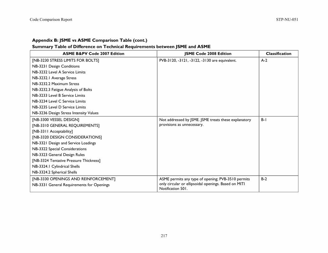
Code Comparison Report STP-NU-051
217
Appendix B: JSME vs ASME Comparison Table (cont.) Summary Table of Difference on Technical Requirements between JSME and ASME
ASME B&PV Code 2007 Edition JSME Code 2008 Edition Classification
[NB-3230 STRESS LIMITS FOR BOLTS] NB-3231 Design Conditions NB-3232 Level A Service Limits NB-3232.1 Average Stress NB-3232.2 Maximum Stress NB-3232.3 Fatigue Analysis of Bolts NB-3233 Level B Service Limits NB-3234 Level C Service Limits NB-3235 Level D Service Limits NB-3236 Design Stress Intensity Values
PVB-3120, -3121, -3122, -3130 are equivalent. A-2
[NB-3300 VESSEL DESIGN] [NB-3310 GENERAL REQUIREMENTS] [NB-3311 Acceptability] [NB-3320 DESIGN CONSIDERATIONS] NB-3321 Design and Service Loadings NB-3322 Special Considerations NB-3323 General Design Rules [NB-3324 Tentative Pressure Thickness] NB-3324.1 Cylindrical Shells NB-3324.2 Spherical Shells
Not addressed by JSME. JSME treats these explanatory provisions as unnecessary.
B-1
[NB-3330 OPENINGS AND REINFORCEMENT] NB-3331 General Requirements for Openings
ASME permits any type of opening; PVB-3510 permits only circular or ellipsoidal openings. Based on MITI Notification 501.
B-2
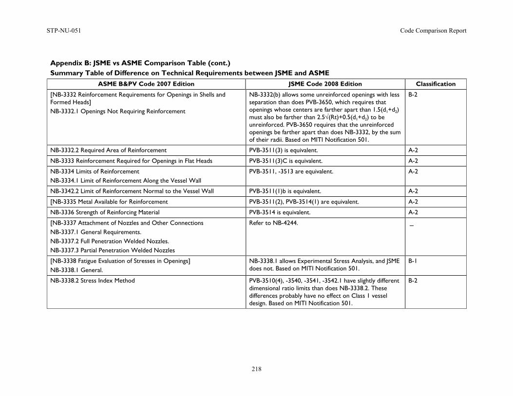
STP-NU-051 Code Comparison Report
218
Appendix B: JSME vs ASME Comparison Table (cont.) Summary Table of Difference on Technical Requirements between JSME and ASME
ASME B&PV Code 2007 Edition JSME Code 2008 Edition Classification
[NB-3332 Reinforcement Requirements for Openings in Shells and Formed Heads] NB-3332.1 Openings Not Requiring Reinforcement
NB-3332(b) allows some unreinforced openings with less separation than does PVB-3650, which requires that openings whose centers are farther apart than 1.5(d1+d2) must also be farther than 2.5√(Rt)+0.5(d1+d2) to be unreinforced. PVB-3650 requires that the unreinforced openings be farther apart than does NB-3332, by the sum of their radii. Based on MITI Notification 501.
B-2
NB-3332.2 Required Area of Reinforcement PVB-3511(3) is equivalent. A-2
NB-3333 Reinforcement Required for Openings in Flat Heads PVB-3511(3)C is equivalent. A-2
NB-3334 Limits of Reinforcement NB-3334.1 Limit of Reinforcement Along the Vessel Wall
PVB-3511, -3513 are equivalent. A-2
NB-3342.2 Limit of Reinforcement Normal to the Vessel Wall PVB-3511(1)b is equivalent. A-2
[NB-3335 Metal Available for Reinforcement PVB-3511(2), PVB-3514(1) are equivalent. A-2
NB-3336 Strength of Reinforcing Material PVB-3514 is equivalent. A-2
[NB-3337 Attachment of Nozzles and Other Connections NB-3337.1 General Requirements. NB-3337.2 Full Penetration Welded Nozzles. NB-3337.3 Partial Penetration Welded Nozzles
Refer to NB-4244. -
[NB-3338 Fatigue Evaluation of Stresses in Openings] NB-3338.1 General.
NB-3338.1 allows Experimental Stress Analysis, and JSME does not. Based on MITI Notification 501.
B-1
NB-3338.2 Stress Index Method PVB-3510(4), -3540, -3541, -3542.1 have slightly different dimensional ratio limits than does NB-3338.2. These differences probably have no effect on Class 1 vessel design. Based on MITI Notification 501.
B-2
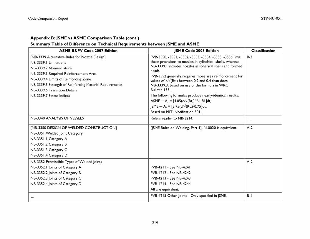
Code Comparison Report STP-NU-051
219
Appendix B: JSME vs ASME Comparison Table (cont.) Summary Table of Difference on Technical Requirements between JSME and ASME
ASME B&PV Code 2007 Edition JSME Code 2008 Edition Classification
[NB-3339 Alternative Rules for Nozzle Design] NB-3339.1 Limitations NB-3339.2 Nomenclature NB-3339.3 Required Reinforcement Area NB-3339.4 Limits of Reinforcing Zone NB-3339.5 Strength of Reinforcing Material Requirements NB-3339.6 Transition Details NB-3339.7 Stress Indices
PVB-3550, -3551, -3352, -3553, -3554, -3555, -3556 limit these provisions to nozzles in cylindrical shells, whereas NB-3339.1 includes nozzles in spherical shells and formed heads. PVB-3552 generally requires more area reinforcement for values of d/√(Rtr) between 0.2 and 0.4 than does NB-3339.3, based on use of the formula in WRC Bulletin 133. The following formulas produce nearly-identical results. ASME ─ Ar = [4.05(d/√(Rtr)
1/2-1.81]dtr JSME ─ Ar = [3.75(d/√(Rtr)-0.75]dtr Based on MITI Notification 501.
B-2
NB-3340 ANALYSIS OF VESSELS Refers reader to NB-3214. -
[NB-3350 DESIGN OF WELDED CONSTRUCTION] NB-3351 Welded Joint Category NB-3351.1 Category A NB-3351.2 Category B NB-3351.3 Category C NB-3351.4 Category D
[JSME Rules on Welding, Part 1], N-0020 is equivalent. A-2
NB-3352 Permissible Types of Welded Joints NB-3352.1 Joints of Category A NB-3352.2 Joints of Category B NB-3352.3 Joints of Category C NB-3352.4 Joints of Category D
PVB-4211 - See NB-4241 PVB-4212 - See NB-4242 PVB-4213 - See NB-4243 PVB-4214 - See NB-4244 All are equivalent.
A-2
- PVB-4215 Other Joints - Only specified in JSME. B-1
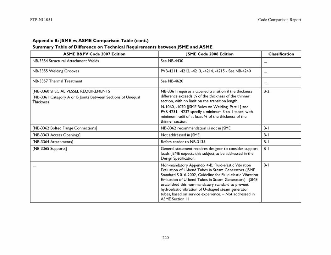
STP-NU-051 Code Comparison Report
220
Appendix B: JSME vs ASME Comparison Table (cont.) Summary Table of Difference on Technical Requirements between JSME and ASME
ASME B&PV Code 2007 Edition JSME Code 2008 Edition Classification
NB-3354 Structural Attachment Welds See NB-4430 -
NB-3355 Welding Grooves PVB-4211, -4212, -4213, -4214, -4215 - See NB-4240 -
NB-3357 Thermal Treatment See NB-4620 -
[NB-3360 SPECIAL VESSEL REQUIREMENTS [NB-3361 Category A or B Joints Between Sections of Unequal Thickness
NB-3361 requires a tapered transition if the thickness difference exceeds ¼ of the thickness of the thinner section, with no limit on the transition length. N-1060, -1070 [JSME Rules on Welding, Part 1] and PVB-4231, -4232 specify a minimum 3-to-1 taper, with minimum radii of at least ½ of the thickness of the thinner section.
B-2
[NB-3362 Bolted Flange Connections] NB-3362 recommendation is not in JSME. B-1
[NB-3363 Access Openings] Not addressed in JSME. B-1
[NB-3364 Attachments] Refers reader to NB-3135. B-1
[NB-3365 Supports] General statement requires designer to consider support loads. JSME expects this subject to be addressed in the Design Specification.
B-1
- Non-mandatory Appendix 4-B, Fluid-elastic Vibration Evaluation of U-bend Tubes in Steam Generators (JSME Standard S 016-2002, Guideline for Fluid-elastic Vibration Evaluation of U-bend Tubes in Steam Generators) - JSME established this non-mandatory standard to prevent hydroelastic vibration of U-shaped steam generator tubes, based on service experience. – Not addressed in ASME Section III
B-1
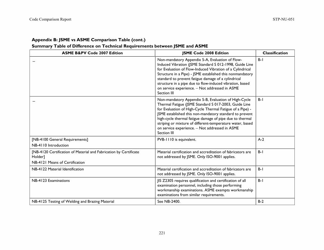
Code Comparison Report STP-NU-051
221
Appendix B: JSME vs ASME Comparison Table (cont.) Summary Table of Difference on Technical Requirements between JSME and ASME
ASME B&PV Code 2007 Edition JSME Code 2008 Edition Classification
- Non-mandatory Appendix 5-A, Evaluation of Flow-Induced Vibration (JSME Standard S 012-1998, Guide Line for Evaluation of Flow-Induced Vibration of a Cylindrical Structure in a Pipe) - JSME established this nonmandatory standard to prevent fatigue damage of a cylindrical structure in a pipe due to flow-induced vibration, based on service experience. – Not addressed in ASME Section III
B-1
- Non-mandatory Appendix 5-B, Evaluation of High-Cycle Thermal Fatigue (JSME Standard S 017-2003, Guide Line for Evaluation of High-Cycle Thermal Fatigue of a Pipe) - JSME established this non-mandatory standard to prevent high-cycle thermal fatigue damage of pipe due to thermal striping or mixture of different-temperature water, based on service experience. – Not addressed in ASME Section III
B-1
[NB-4100 General Requirements] NB-4110 Introduction
PVB-1110 is equivalent. A-2
[NB-4120 Certification of Material and Fabrication by Certificate Holder] NB-4121 Means of Certification
Material certification and accreditation of fabricators are not addressed by JSME. Only ISO-9001 applies.
B-1
NB-4122 Material Identification Material certification and accreditation of fabricators are not addressed by JSME. Only ISO-9001 applies.
B-1
NB-4123 Examinations JIS Z2305 requires qualification and certification of all examination personnel, including those performing workmanship examinations. ASME exempts workmanship examinations from similar requirements.
B-1
NB-4125 Testing of Welding and Brazing Material See NB-2400. B-2
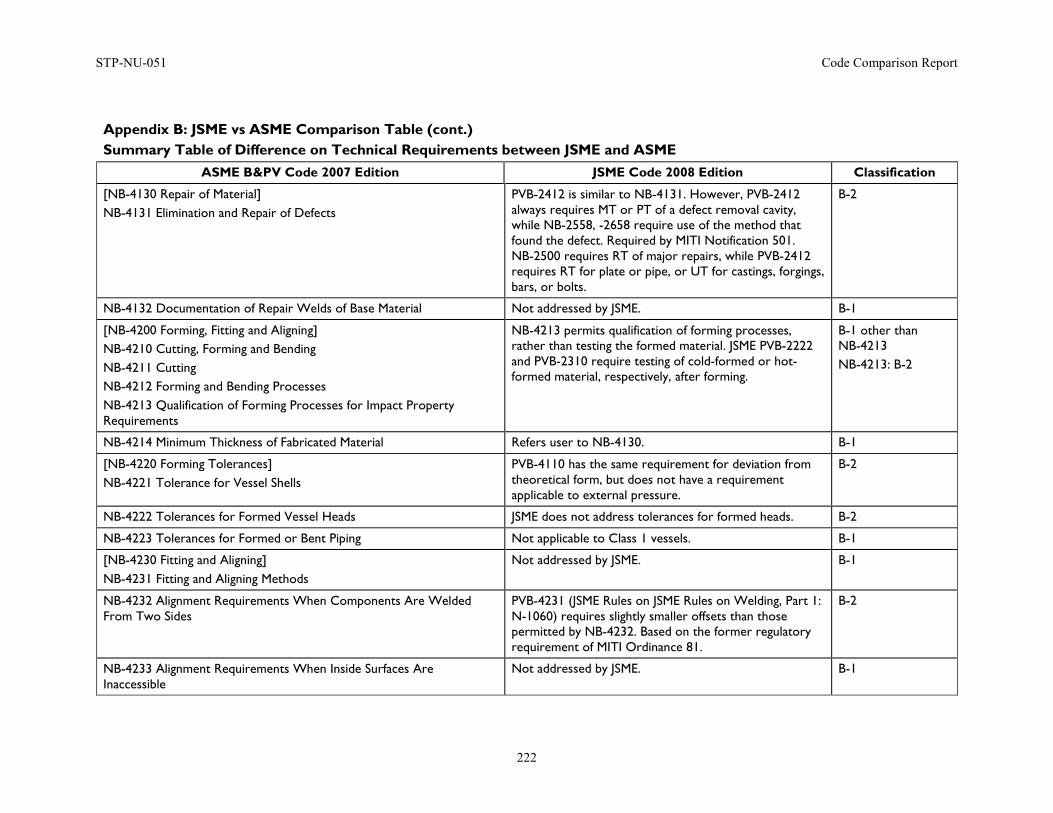
STP-NU-051 Code Comparison Report
222
Appendix B: JSME vs ASME Comparison Table (cont.) Summary Table of Difference on Technical Requirements between JSME and ASME
ASME B&PV Code 2007 Edition JSME Code 2008 Edition Classification
[NB-4130 Repair of Material] NB-4131 Elimination and Repair of Defects
PVB-2412 is similar to NB-4131. However, PVB-2412 always requires MT or PT of a defect removal cavity, while NB-2558, -2658 require use of the method that found the defect. Required by MITI Notification 501. NB-2500 requires RT of major repairs, while PVB-2412 requires RT for plate or pipe, or UT for castings, forgings, bars, or bolts.
B-2
NB-4132 Documentation of Repair Welds of Base Material Not addressed by JSME. B-1
[NB-4200 Forming, Fitting and Aligning] NB-4210 Cutting, Forming and Bending NB-4211 Cutting NB-4212 Forming and Bending Processes NB-4213 Qualification of Forming Processes for Impact Property Requirements
NB-4213 permits qualification of forming processes, rather than testing the formed material. JSME PVB-2222 and PVB-2310 require testing of cold-formed or hot-formed material, respectively, after forming.
B-1 other than NB-4213 NB-4213: B-2
NB-4214 Minimum Thickness of Fabricated Material Refers user to NB-4130. B-1
[NB-4220 Forming Tolerances] NB-4221 Tolerance for Vessel Shells
PVB-4110 has the same requirement for deviation from theoretical form, but does not have a requirement applicable to external pressure.
B-2
NB-4222 Tolerances for Formed Vessel Heads JSME does not address tolerances for formed heads. B-2
NB-4223 Tolerances for Formed or Bent Piping Not applicable to Class 1 vessels. B-1
[NB-4230 Fitting and Aligning] NB-4231 Fitting and Aligning Methods
Not addressed by JSME. B-1
NB-4232 Alignment Requirements When Components Are Welded From Two Sides
PVB-4231 (JSME Rules on JSME Rules on Welding, Part 1: N-1060) requires slightly smaller offsets than those permitted by NB-4232. Based on the former regulatory requirement of MITI Ordinance 81.
B-2
NB-4233 Alignment Requirements When Inside Surfaces Are Inaccessible
Not addressed by JSME. B-1
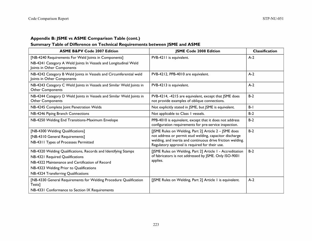
Code Comparison Report STP-NU-051
223
Appendix B: JSME vs ASME Comparison Table (cont.) Summary Table of Difference on Technical Requirements between JSME and ASME
ASME B&PV Code 2007 Edition JSME Code 2008 Edition Classification
[NB-4240 Requirements For Weld Joints in Components] NB-4241 Category A Weld Joints In Vessels and Longitudinal Weld Joints in Other Components
PVB-4211 is equivalent. A-2
NB-4242 Category B Weld Joints in Vessels and Circumferential weld Joints in Other Components
PVB-4212, PPB-4010 are equivalent. A-2
NB-4243 Category C Weld Joints in Vessels and Similar Weld Joints in Other Components
PVB-4213 is equivalent. A-2
NB-4244 Category D Weld Joints in Vessels and Similar Weld Joints in Other Components
PVB-4214, -4215 are equivalent, except that JSME does not provide examples of oblique connections.
B-2
NB-4245 Complete Joint Penetration Welds Not explicitly stated in JSME, but JSME is equivalent. B-1
NB-4246 Piping Branch Connections Not applicable to Class 1 vessels. B-2
NB-4250 Welding End Transitions-Maximum Envelope PPB-4010 is equivalent, except that it does not address configuration requirements for pre-service inspection.
B-2
[NB-4300 Welding Qualifications] [NB-4310 General Requirements] NB-4311 Types of Processes Permitted
[JSME Rules on Welding, Part 2] Article 2 – JSME does not address or permit stud welding, capacitor discharge welding, and inertia and continuous drive friction welding. Regulatory approval is required for their use.
B-2
NB-4320 Welding Qualifications, Records and Identifying Stamps NB-4321 Required Qualifications NB-4322 Maintenance and Certification of Record NB-4323 Welding Prior to Qualifications NB-4324 Transferring Qualifications
[JSME Rules on Welding, Part 2] Article 1 - Accreditation of fabricators is not addressed by JSME. Only ISO-9001 applies.
B-2
[NB-4330 General Requirements for Welding Procedure Qualification Tests] NB-4331 Conformance to Section IX Requirements
[JSME Rules on Welding, Part 2] Article 1 is equivalent. A-2
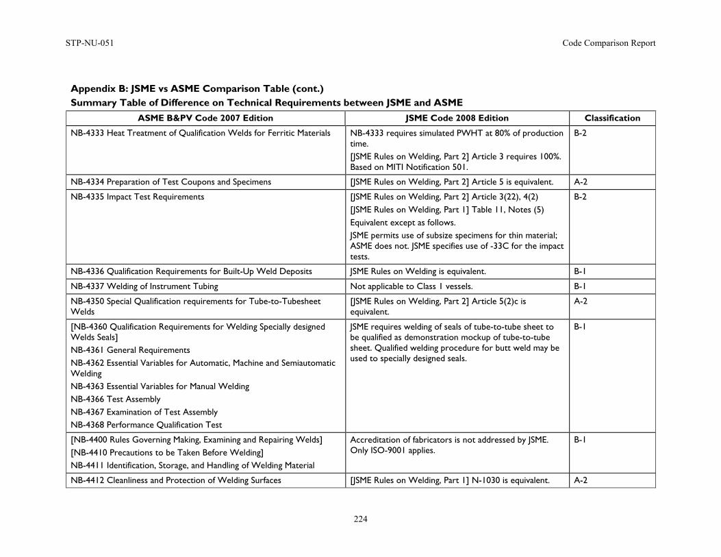
STP-NU-051 Code Comparison Report
224
Appendix B: JSME vs ASME Comparison Table (cont.) Summary Table of Difference on Technical Requirements between JSME and ASME
ASME B&PV Code 2007 Edition JSME Code 2008 Edition Classification
NB-4333 Heat Treatment of Qualification Welds for Ferritic Materials NB-4333 requires simulated PWHT at 80% of production time. [JSME Rules on Welding, Part 2] Article 3 requires 100%. Based on MITI Notification 501.
B-2
NB-4334 Preparation of Test Coupons and Specimens [JSME Rules on Welding, Part 2] Article 5 is equivalent. A-2
NB-4335 Impact Test Requirements [JSME Rules on Welding, Part 2] Article 3(22), 4(2) [JSME Rules on Welding, Part 1] Table 11, Notes (5) Equivalent except as follows. JSME permits use of subsize specimens for thin material; ASME does not. JSME specifies use of -33C for the impact tests.
B-2
NB-4336 Qualification Requirements for Built-Up Weld Deposits JSME Rules on Welding is equivalent. B-1
NB-4337 Welding of Instrument Tubing Not applicable to Class 1 vessels. B-1
NB-4350 Special Qualification requirements for Tube-to-Tubesheet Welds
[JSME Rules on Welding, Part 2] Article 5(2)c is equivalent.
A-2
[NB-4360 Qualification Requirements for Welding Specially designed Welds Seals] NB-4361 General Requirements NB-4362 Essential Variables for Automatic, Machine and Semiautomatic Welding NB-4363 Essential Variables for Manual Welding NB-4366 Test Assembly NB-4367 Examination of Test Assembly NB-4368 Performance Qualification Test
JSME requires welding of seals of tube-to-tube sheet to be qualified as demonstration mockup of tube-to-tube sheet. Qualified welding procedure for butt weld may be used to specially designed seals.
B-1
[NB-4400 Rules Governing Making, Examining and Repairing Welds] [NB-4410 Precautions to be Taken Before Welding] NB-4411 Identification, Storage, and Handling of Welding Material
Accreditation of fabricators is not addressed by JSME. Only ISO-9001 applies.
B-1
NB-4412 Cleanliness and Protection of Welding Surfaces [JSME Rules on Welding, Part 1] N-1030 is equivalent. A-2
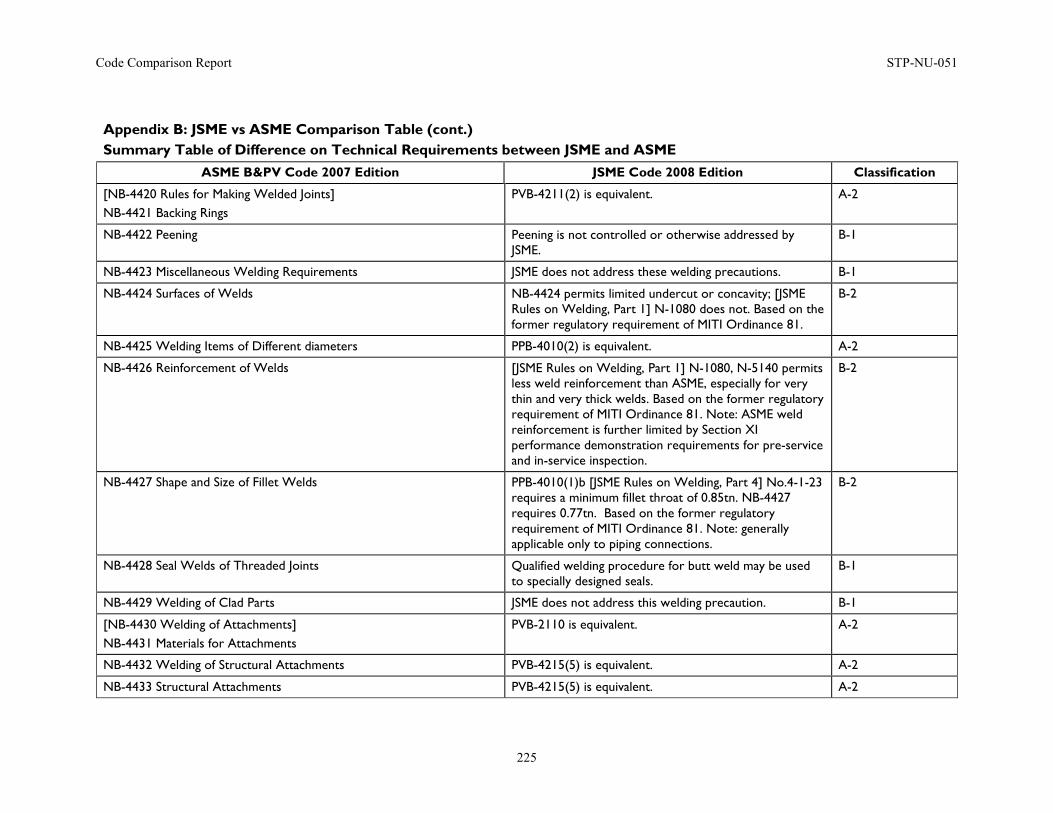
Code Comparison Report STP-NU-051
225
Appendix B: JSME vs ASME Comparison Table (cont.) Summary Table of Difference on Technical Requirements between JSME and ASME
ASME B&PV Code 2007 Edition JSME Code 2008 Edition Classification
[NB-4420 Rules for Making Welded Joints] NB-4421 Backing Rings
PVB-4211(2) is equivalent. A-2
NB-4422 Peening Peening is not controlled or otherwise addressed by JSME.
B-1
NB-4423 Miscellaneous Welding Requirements JSME does not address these welding precautions. B-1
NB-4424 Surfaces of Welds NB-4424 permits limited undercut or concavity; [JSME Rules on Welding, Part 1] N-1080 does not. Based on the former regulatory requirement of MITI Ordinance 81.
B-2
NB-4425 Welding Items of Different diameters PPB-4010(2) is equivalent. A-2
NB-4426 Reinforcement of Welds [JSME Rules on Welding, Part 1] N-1080, N-5140 permits less weld reinforcement than ASME, especially for very thin and very thick welds. Based on the former regulatory requirement of MITI Ordinance 81. Note: ASME weld reinforcement is further limited by Section XI performance demonstration requirements for pre-service and in-service inspection.
B-2
NB-4427 Shape and Size of Fillet Welds PPB-4010(1)b [JSME Rules on Welding, Part 4] No.4-1-23 requires a minimum fillet throat of 0.85tn. NB-4427 requires 0.77tn. Based on the former regulatory requirement of MITI Ordinance 81. Note: generally applicable only to piping connections.
B-2
NB-4428 Seal Welds of Threaded Joints Qualified welding procedure for butt weld may be used to specially designed seals.
B-1
NB-4429 Welding of Clad Parts JSME does not address this welding precaution. B-1
[NB-4430 Welding of Attachments] NB-4431 Materials for Attachments
PVB-2110 is equivalent. A-2
NB-4432 Welding of Structural Attachments PVB-4215(5) is equivalent. A-2
NB-4433 Structural Attachments PVB-4215(5) is equivalent. A-2
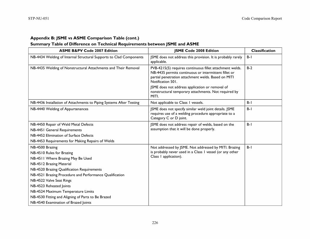
STP-NU-051 Code Comparison Report
226
Appendix B: JSME vs ASME Comparison Table (cont.) Summary Table of Difference on Technical Requirements between JSME and ASME
ASME B&PV Code 2007 Edition JSME Code 2008 Edition Classification
NB-4434 Welding of Internal Structural Supports to Clad Components JSME does not address this provision. It is probably rarely applicable.
B-1
NB-4435 Welding of Nonstructural Attachments and Their Removal PVB-4215(5) requires continuous fillet attachment welds. NB-4435 permits continuous or intermittent fillet or partial penetration attachment welds. Based on MITI Notification 501. JSME does not address application or removal of nonstructural temporary attachments. Not required by MITI.
B-2
NB-4436 Installation of Attachments to Piping Systems After Testing Not applicable to Class 1 vessels. B-1
NB-4440 Welding of Appurtenances JSME does not specify similar weld joint details. JSME requires use of a welding procedure appropriate to a Category C or D joint.
B-1
NB-4450 Repair of Weld Metal Defects NB-4451 General Requirements NB-4452 Elimination of Surface Defects NB-4453 Requirements for Making Repairs of Welds
JSME does not address repair of welds, based on the assumption that it will be done properly.
B-1
NB-4500 Brazing NB-4510 Rules for Brazing NB-4511 Where Brazing May Be Used NB-4512 Brazing Material NB-4520 Brazing Qualification Requirements NB-4521 Brazing Procedure and Performance Qualification NB-4522 Valve Seat Rings NB-4523 Reheated Joints NB-4524 Maximum Temperature Limits NB-4530 Fitting and Aligning of Parts to Be Brazed NB-4540 Examination of Brazed Joints
Not addressed by JSME. Not addressed by MITI. Brazing is probably never used in a Class 1 vessel (or any other Class 1 application).
B-1
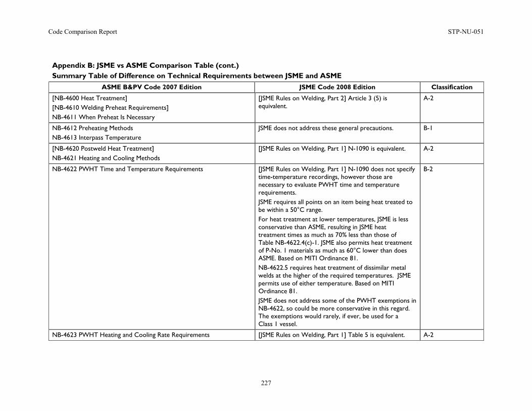
Code Comparison Report STP-NU-051
227
Appendix B: JSME vs ASME Comparison Table (cont.) Summary Table of Difference on Technical Requirements between JSME and ASME
ASME B&PV Code 2007 Edition JSME Code 2008 Edition Classification
[NB-4600 Heat Treatment] [NB-4610 Welding Preheat Requirements] NB-4611 When Preheat Is Necessary
[JSME Rules on Welding, Part 2] Article 3 (5) is equivalent.
A-2
NB-4612 Preheating Methods NB-4613 Interpass Temperature
JSME does not address these general precautions. B-1
[NB-4620 Postweld Heat Treatment] NB-4621 Heating and Cooling Methods
[JSME Rules on Welding, Part 1] N-1090 is equivalent. A-2
NB-4622 PWHT Time and Temperature Requirements [JSME Rules on Welding, Part 1] N-1090 does not specify time-temperature recordings, however those are necessary to evaluate PWHT time and temperature requirements. JSME requires all points on an item being heat treated to be within a 50°C range. For heat treatment at lower temperatures, JSME is less conservative than ASME, resulting in JSME heat treatment times as much as 70% less than those of Table NB-4622.4(c)-1. JSME also permits heat treatment of P-No. 1 materials as much as 60°C lower than does ASME. Based on MITI Ordinance 81. NB-4622.5 requires heat treatment of dissimilar metal welds at the higher of the required temperatures. JSME permits use of either temperature. Based on MITI Ordinance 81. JSME does not address some of the PWHT exemptions in NB-4622, so could be more conservative in this regard. The exemptions would rarely, if ever, be used for a Class 1 vessel.
B-2
NB-4623 PWHT Heating and Cooling Rate Requirements [JSME Rules on Welding, Part 1] Table 5 is equivalent. A-2
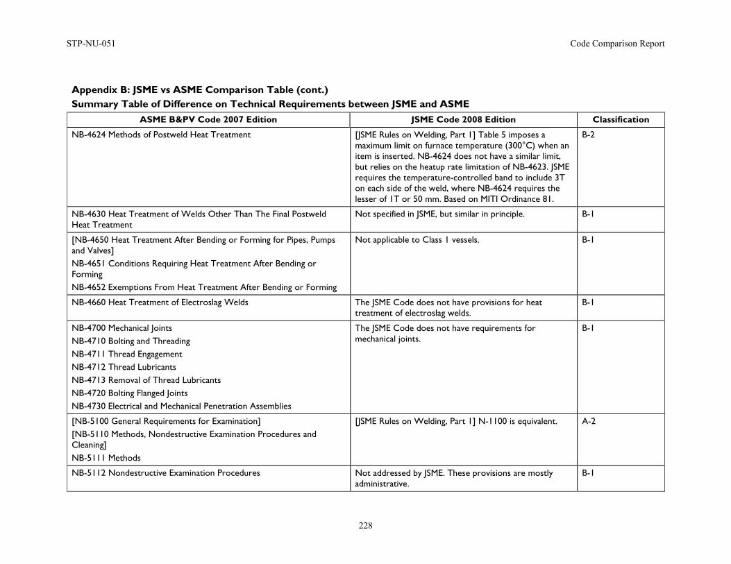
STP-NU-051 Code Comparison Report
228
Appendix B: JSME vs ASME Comparison Table (cont.) Summary Table of Difference on Technical Requirements between JSME and ASME
ASME B&PV Code 2007 Edition JSME Code 2008 Edition Classification
NB-4624 Methods of Postweld Heat Treatment [JSME Rules on Welding, Part 1] Table 5 imposes a maximum limit on furnace temperature (300°C) when an item is inserted. NB-4624 does not have a similar limit, but relies on the heatup rate limitation of NB-4623. JSME requires the temperature-controlled band to include 3T on each side of the weld, where NB-4624 requires the lesser of 1T or 50 mm. Based on MITI Ordinance 81.
B-2
NB-4630 Heat Treatment of Welds Other Than The Final Postweld Heat Treatment
Not specified in JSME, but similar in principle. B-1
[NB-4650 Heat Treatment After Bending or Forming for Pipes, Pumps and Valves] NB-4651 Conditions Requiring Heat Treatment After Bending or Forming NB-4652 Exemptions From Heat Treatment After Bending or Forming
Not applicable to Class 1 vessels. B-1
NB-4660 Heat Treatment of Electroslag Welds The JSME Code does not have provisions for heat treatment of electroslag welds.
B-1
NB-4700 Mechanical Joints NB-4710 Bolting and Threading NB-4711 Thread Engagement NB-4712 Thread Lubricants NB-4713 Removal of Thread Lubricants NB-4720 Bolting Flanged Joints NB-4730 Electrical and Mechanical Penetration Assemblies
The JSME Code does not have requirements for mechanical joints.
B-1
[NB-5100 General Requirements for Examination] [NB-5110 Methods, Nondestructive Examination Procedures and Cleaning] NB-5111 Methods
[JSME Rules on Welding, Part 1] N-1100 is equivalent. A-2
NB-5112 Nondestructive Examination Procedures Not addressed by JSME. These provisions are mostly administrative.
B-1
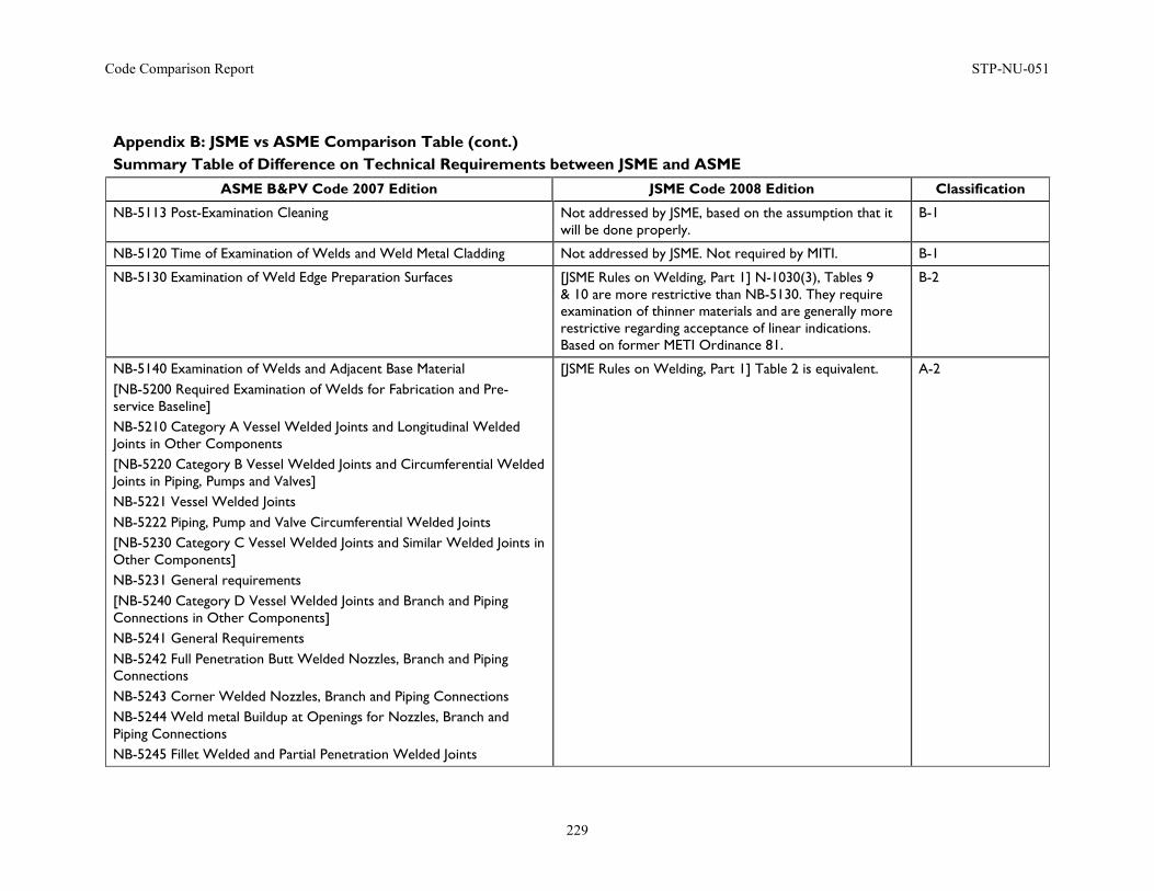
Code Comparison Report STP-NU-051
229
Appendix B: JSME vs ASME Comparison Table (cont.) Summary Table of Difference on Technical Requirements between JSME and ASME
ASME B&PV Code 2007 Edition JSME Code 2008 Edition Classification
NB-5113 Post-Examination Cleaning Not addressed by JSME, based on the assumption that it will be done properly.
B-1
NB-5120 Time of Examination of Welds and Weld Metal Cladding Not addressed by JSME. Not required by MITI. B-1
NB-5130 Examination of Weld Edge Preparation Surfaces [JSME Rules on Welding, Part 1] N-1030(3), Tables 9 & 10 are more restrictive than NB-5130. They require examination of thinner materials and are generally more restrictive regarding acceptance of linear indications. Based on former METI Ordinance 81.
B-2
NB-5140 Examination of Welds and Adjacent Base Material [NB-5200 Required Examination of Welds for Fabrication and Pre-service Baseline] NB-5210 Category A Vessel Welded Joints and Longitudinal Welded Joints in Other Components [NB-5220 Category B Vessel Welded Joints and Circumferential Welded Joints in Piping, Pumps and Valves] NB-5221 Vessel Welded Joints NB-5222 Piping, Pump and Valve Circumferential Welded Joints [NB-5230 Category C Vessel Welded Joints and Similar Welded Joints in Other Components] NB-5231 General requirements [NB-5240 Category D Vessel Welded Joints and Branch and Piping Connections in Other Components] NB-5241 General Requirements NB-5242 Full Penetration Butt Welded Nozzles, Branch and Piping Connections NB-5243 Corner Welded Nozzles, Branch and Piping Connections NB-5244 Weld metal Buildup at Openings for Nozzles, Branch and Piping Connections NB-5245 Fillet Welded and Partial Penetration Welded Joints
[JSME Rules on Welding, Part 1] Table 2 is equivalent. A-2
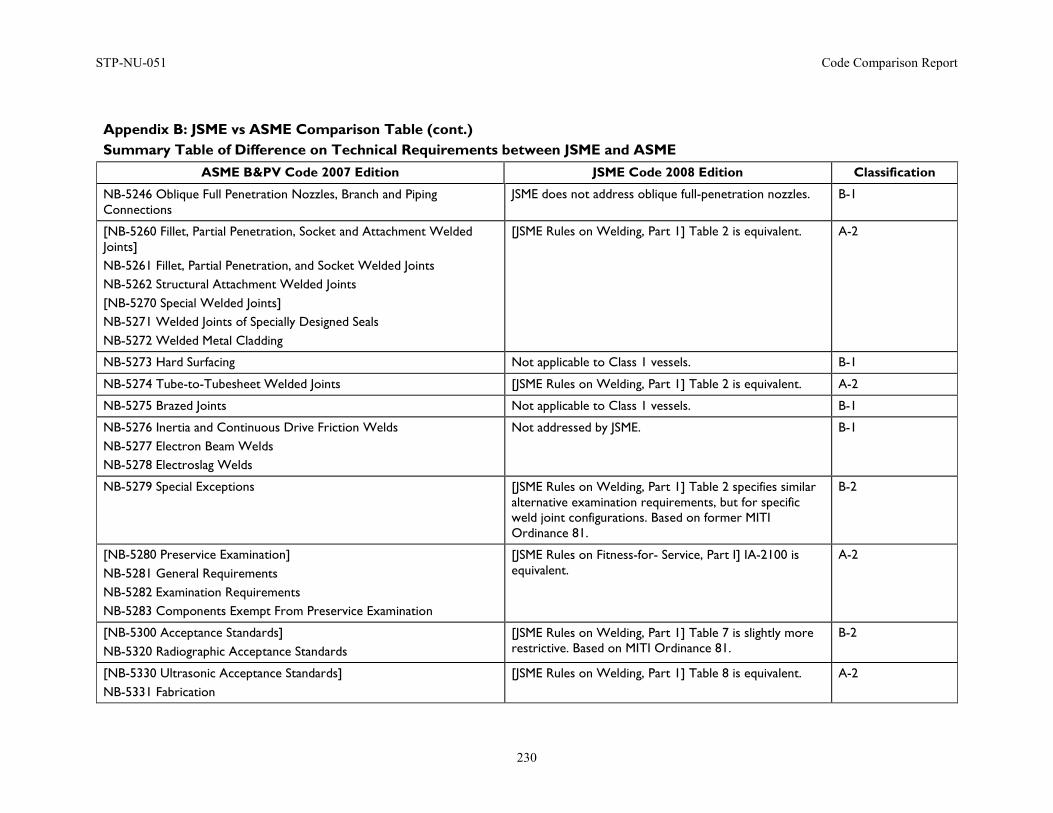
STP-NU-051 Code Comparison Report
230
Appendix B: JSME vs ASME Comparison Table (cont.) Summary Table of Difference on Technical Requirements between JSME and ASME
ASME B&PV Code 2007 Edition JSME Code 2008 Edition Classification
NB-5246 Oblique Full Penetration Nozzles, Branch and Piping Connections
JSME does not address oblique full-penetration nozzles. B-1
[NB-5260 Fillet, Partial Penetration, Socket and Attachment Welded Joints] NB-5261 Fillet, Partial Penetration, and Socket Welded Joints NB-5262 Structural Attachment Welded Joints [NB-5270 Special Welded Joints] NB-5271 Welded Joints of Specially Designed Seals NB-5272 Welded Metal Cladding
[JSME Rules on Welding, Part 1] Table 2 is equivalent. A-2
NB-5273 Hard Surfacing Not applicable to Class 1 vessels. B-1
NB-5274 Tube-to-Tubesheet Welded Joints [JSME Rules on Welding, Part 1] Table 2 is equivalent. A-2
NB-5275 Brazed Joints Not applicable to Class 1 vessels. B-1
NB-5276 Inertia and Continuous Drive Friction Welds NB-5277 Electron Beam Welds NB-5278 Electroslag Welds
Not addressed by JSME. B-1
NB-5279 Special Exceptions [JSME Rules on Welding, Part 1] Table 2 specifies similar alternative examination requirements, but for specific weld joint configurations. Based on former MITI Ordinance 81.
B-2
[NB-5280 Preservice Examination] NB-5281 General Requirements NB-5282 Examination Requirements NB-5283 Components Exempt From Preservice Examination
[JSME Rules on Fitness-for- Service, Part I] IA-2100 is equivalent.
A-2
[NB-5300 Acceptance Standards] NB-5320 Radiographic Acceptance Standards
[JSME Rules on Welding, Part 1] Table 7 is slightly more restrictive. Based on MITI Ordinance 81.
B-2
[NB-5330 Ultrasonic Acceptance Standards] NB-5331 Fabrication
[JSME Rules on Welding, Part 1] Table 8 is equivalent. A-2
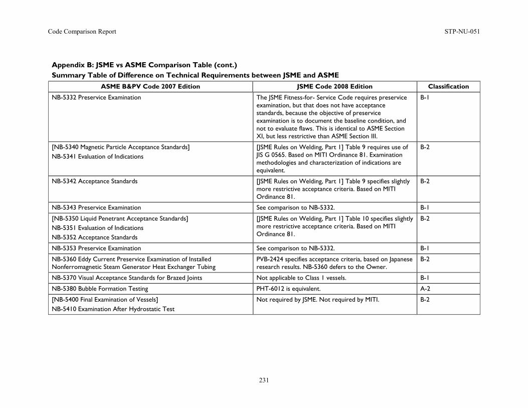
Code Comparison Report STP-NU-051
231
Appendix B: JSME vs ASME Comparison Table (cont.) Summary Table of Difference on Technical Requirements between JSME and ASME
ASME B&PV Code 2007 Edition JSME Code 2008 Edition Classification
NB-5332 Preservice Examination The JSME Fitness-for- Service Code requires preservice examination, but that does not have acceptance standards, because the objective of preservice examination is to document the baseline condition, and not to evaluate flaws. This is identical to ASME Section XI, but less restrictive than ASME Section III.
B-1
[NB-5340 Magnetic Particle Acceptance Standards] NB-5341 Evaluation of Indications
[JSME Rules on Welding, Part 1] Table 9 requires use of JIS G 0565. Based on MITI Ordinance 81. Examination methodologies and characterization of indications are equivalent.
B-2
NB-5342 Acceptance Standards [JSME Rules on Welding, Part 1] Table 9 specifies slightly more restrictive acceptance criteria. Based on MITI Ordinance 81.
B-2
NB-5343 Preservice Examination See comparison to NB-5332. B-1
[NB-5350 Liquid Penetrant Acceptance Standards] NB-5351 Evaluation of Indications NB-5352 Acceptance Standards
[JSME Rules on Welding, Part 1] Table 10 specifies slightly more restrictive acceptance criteria. Based on MITI Ordinance 81.
B-2
NB-5353 Preservice Examination See comparison to NB-5332. B-1
NB-5360 Eddy Current Preservice Examination of Installed Nonferromagnetic Steam Generator Heat Exchanger Tubing
PVB-2424 specifies acceptance criteria, based on Japanese research results. NB-5360 defers to the Owner.
B-2
NB-5370 Visual Acceptance Standards for Brazed Joints Not applicable to Class 1 vessels. B-1
NB-5380 Bubble Formation Testing PHT-6012 is equivalent. A-2
[NB-5400 Final Examination of Vessels] NB-5410 Examination After Hydrostatic Test
Not required by JSME. Not required by MITI. B-2
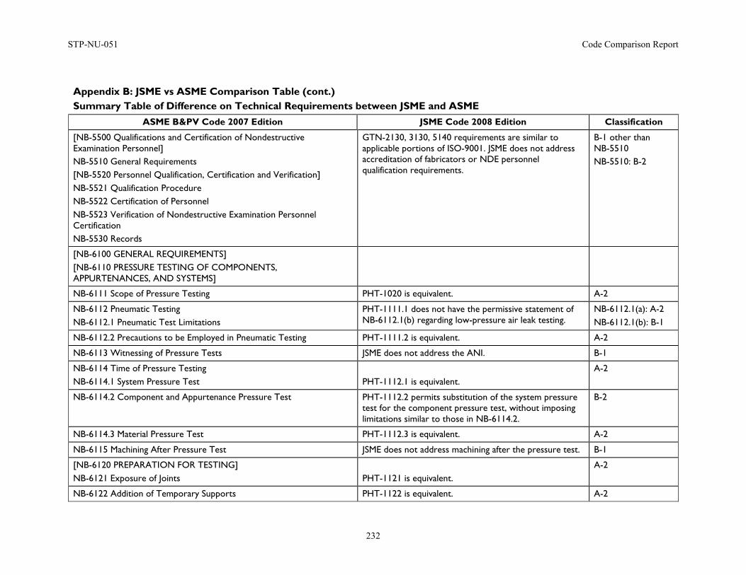
STP-NU-051 Code Comparison Report
232
Appendix B: JSME vs ASME Comparison Table (cont.) Summary Table of Difference on Technical Requirements between JSME and ASME
ASME B&PV Code 2007 Edition JSME Code 2008 Edition Classification
[NB-5500 Qualifications and Certification of Nondestructive Examination Personnel] NB-5510 General Requirements [NB-5520 Personnel Qualification, Certification and Verification] NB-5521 Qualification Procedure NB-5522 Certification of Personnel NB-5523 Verification of Nondestructive Examination Personnel Certification NB-5530 Records
GTN-2130, 3130, 5140 requirements are similar to applicable portions of ISO-9001. JSME does not address accreditation of fabricators or NDE personnel qualification requirements.
B-1 other than NB-5510 NB-5510: B-2
[NB-6100 GENERAL REQUIREMENTS] [NB-6110 PRESSURE TESTING OF COMPONENTS, APPURTENANCES, AND SYSTEMS]
NB-6111 Scope of Pressure Testing PHT-1020 is equivalent. A-2
NB-6112 Pneumatic Testing NB-6112.1 Pneumatic Test Limitations
PHT-1111.1 does not have the permissive statement of NB-6112.1(b) regarding low-pressure air leak testing.
NB-6112.1(a): A-2 NB-6112.1(b): B-1
NB-6112.2 Precautions to be Employed in Pneumatic Testing PHT-1111.2 is equivalent. A-2
NB-6113 Witnessing of Pressure Tests JSME does not address the ANI. B-1
NB-6114 Time of Pressure Testing NB-6114.1 System Pressure Test
PHT-1112.1 is equivalent.
A-2
NB-6114.2 Component and Appurtenance Pressure Test PHT-1112.2 permits substitution of the system pressure test for the component pressure test, without imposing limitations similar to those in NB-6114.2.
B-2
NB-6114.3 Material Pressure Test PHT-1112.3 is equivalent. A-2
NB-6115 Machining After Pressure Test JSME does not address machining after the pressure test. B-1
[NB-6120 PREPARATION FOR TESTING] NB-6121 Exposure of Joints
PHT-1121 is equivalent.
A-2
NB-6122 Addition of Temporary Supports PHT-1122 is equivalent. A-2
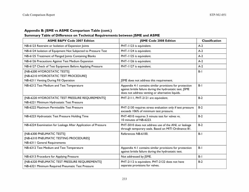
Code Comparison Report STP-NU-051
233
Appendix B: JSME vs ASME Comparison Table (cont.) Summary Table of Difference on Technical Requirements between JSME and ASME
ASME B&PV Code 2007 Edition JSME Code 2008 Edition Classification
NB-6123 Restraint or Isolation of Expansion Joints PHT-1123 is equivalent. A-2
NB-6124 Isolation of Equipment Not Subjected to Pressure Test PHT-1124 is equivalent. A-2
NB-6125 Treatment of Flanged Joints Containing Blanks PHT-1125 is equivalent. A-2
NB-6126 Precautions Against Test Medium Expansion PHT-1126 is equivalent. A-2
NB-6127 Check of Test Equipment Before Applying Pressure PHT-1127 is equivalent. A-2
[NB-6200 HYDROSTATIC TESTS] [NB-6210 HYDROSTATIC TEST PROCEDURE] NB-6211 Venting During Fill Operation
JSME does not address this requirement.
B-1
NB-6212 Test Medium and Test Temperature Appendix 4-1 contains similar provisions for protection against brittle failure during the hydrostatic test. JSME does not address venting or alternative liquids.
B-1
[NB-6220 HYDROSTATIC TEST PRESSURE REQUIREMENTS] NB-6221 Minimum Hydrostatic Test Pressure
PHT-2111, PHT-2121 are equivalent. B-2
NB-6222 Maximum Permissible Test Pressure PHT-2130 requires stress evaluation only if test pressure exceeds 106% of minimum test pressure.
B-2
NB-6223 Hydrostatic Test Pressure Holding Time PHT-4010 requires 3 minute test for valves vs. 10 minutes of NB-6223.
B-2
NB-6224 Examination for Leakage After Application of Pressure PHT-5010 does not address use of the ANI, or leakage through temporary seals. Based on MITI Ordinance 81.
B-2
[NB-6300 PNEUMATIC TESTS] [NB-6310 PNEUMATIC TESTING PROCEDURES] NB-6311 General Requirements
References NB-6100. B-1
NB-6312 Test Medium and Test Temperature Appendix 4-1 contains similar provisions for protection against brittle failure during the hydrostatic test.
B-1
NB-6313 Procedure for Applying Pressure Not addressed by JSME. B-1
[NB-6320 PNEUMATIC TEST PRESSURE REQUIREMENTS] NB-6321 Minimum Required Pneumatic Test Pressure
PHT-2112 is equivalent. PHT-2122 does not have separate provisions for valves.
B-2
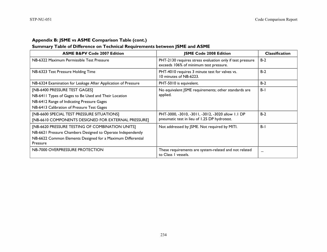
STP-NU-051 Code Comparison Report
234
Appendix B: JSME vs ASME Comparison Table (cont.) Summary Table of Difference on Technical Requirements between JSME and ASME
ASME B&PV Code 2007 Edition JSME Code 2008 Edition Classification
NB-6322 Maximum Permissible Test Pressure PHT-2130 requires stress evaluation only if test pressure exceeds 106% of minimum test pressure.
B-2
NB-6323 Test Pressure Holding Time PHT-4010 requires 3 minute test for valves vs. 10 minutes of NB-6223.
B-2
NB-6324 Examination for Leakage After Application of Pressure PHT-5010 is equivalent. B-2
[NB-6400 PRESSURE TEST GAGES] NB-6411 Types of Gages to Be Used and Their Location NB-6412 Range of Indicating Pressure Gages NB-6413 Calibration of Pressure Test Gages
No equivalent JSME requirements; other standards are applied.
B-1
[NB-6600 SPECIAL TEST PRESSURE SITUATIONS] [NB-6610 COMPONENTS DESIGNED FOR EXTERNAL PRESSURE]
PHT-3000, -3010, -3011, -3012, -3020 allow 1.1 DP pneumatic test in lieu of 1.25 DP hydrotest.
B-2
[NB-6620 PRESSURE TESTING OF COMBINATION UNITS] NB-6621 Pressure Chambers Designed to Operate Independently NB-6622 Common Elements Designed for a Maximum Differential Pressure
Not addressed by JSME. Not required by MITI. B-1
NB-7000 OVERPRESSURE PROTECTION These requirements are system-related and not related to Class 1 vessels.
-
Code Comparison Report STP-NU-051
235
APPENDIX C: KEPIC VERSUS ASME SECTION III DETAILED COMPARISON TABLE
Appendix C1: KEPIC MNB Versus ASME Section III NB Appendix C2: KEPIC MNA Versus ASME Section III NCA
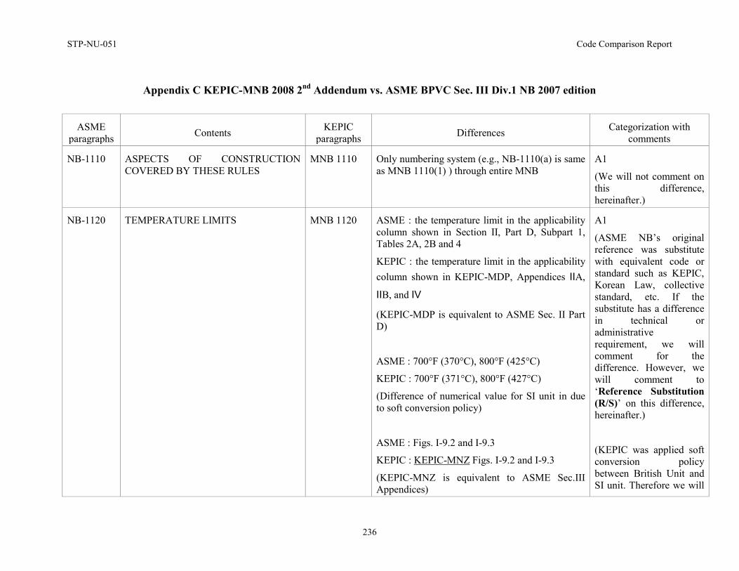
STP-NU-051 Code Comparison Report
236
Appendix C KEPIC-MNB 2008 2nd Addendum vs. ASME BPVC Sec. III Div.1 NB 2007 edition
ASME paragraphs Contents KEPIC
paragraphs Differences Categorization with comments
NB-1110 ASPECTS OF CONSTRUCTION COVERED BY THESE RULES
MNB 1110 Only numbering system (e.g., NB-1110(a) is same as MNB 1110(1) ) through entire MNB
A1
(We will not comment on this difference, hereinafter.)
NB-1120 TEMPERATURE LIMITS
MNB 1120 ASME : the temperature limit in the applicability column shown in Section II, Part D, Subpart 1, Tables 2A, 2B and 4
KEPIC : the temperature limit in the applicability column shown in KEPIC-MDP, Appendices ⅡA,
ⅡB, and Ⅳ
(KEPIC-MDP is equivalent to ASME Sec. II Part D)
ASME : 700°F (370°C), 800°F (425°C)
KEPIC : 700°F (371°C), 800°F (427°C)
(Difference of numerical value for SI unit in due to soft conversion policy)
ASME : Figs. I-9.2 and I-9.3
KEPIC : KEPIC-MNZ Figs. I-9.2 and I-9.3
(KEPIC-MNZ is equivalent to ASME Sec.III Appendices)
A1
(ASME NB’s original reference was substitute with equivalent code or standard such as KEPIC, Korean Law, collective standard, etc. If the substitute has a difference in technical or administrative requirement, we will comment for the difference. However, we will comment to ‘Reference Substitution (R/S)’ on this difference, hereinafter.)
(KEPIC was applied soft conversion policy between British Unit and SI unit. Therefore we will
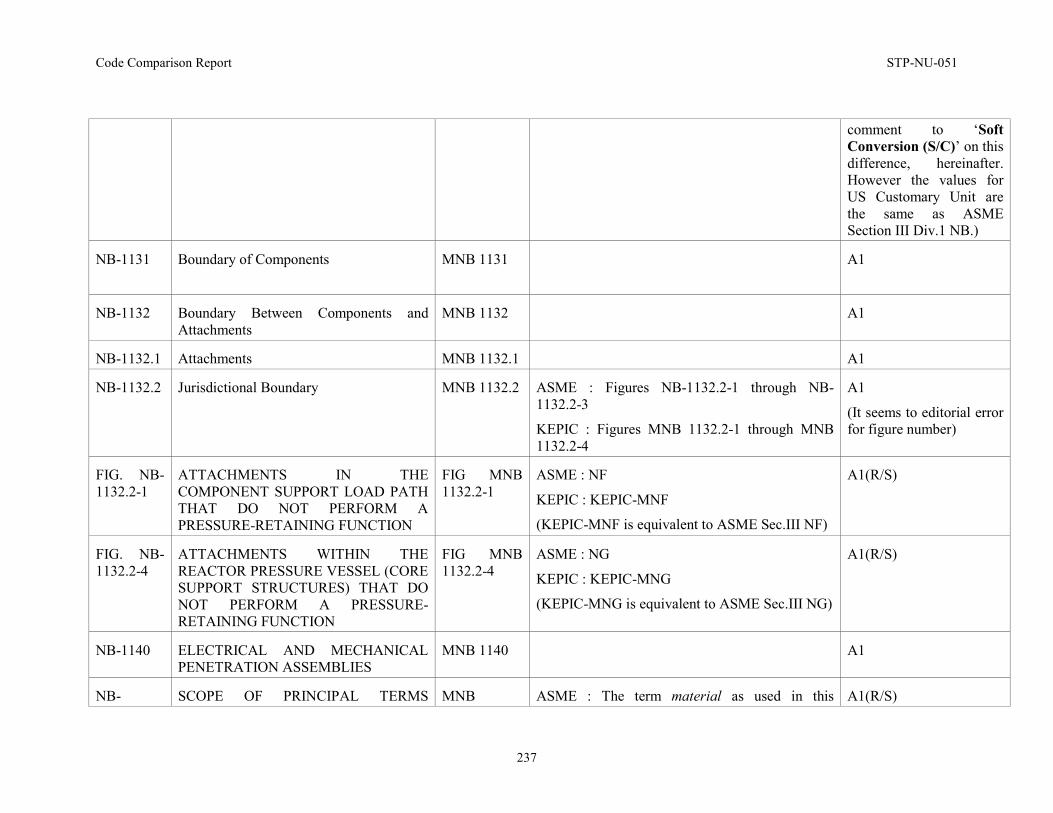
Code Comparison Report STP-NU-051
237
comment to ‘Soft Conversion (S/C)’ on this difference, hereinafter. However the values for US Customary Unit are the same as ASME Section III Div.1 NB.)
NB-1131 Boundary of Components
MNB 1131 A1
NB-1132 Boundary Between Components and Attachments
MNB 1132 A1
NB-1132.1 Attachments MNB 1132.1 A1
NB-1132.2 Jurisdictional Boundary MNB 1132.2 ASME : Figures NB-1132.2-1 through NB-1132.2-3
KEPIC : Figures MNB 1132.2-1 through MNB 1132.2-4
A1
(It seems to editorial error for figure number)
FIG. NB-1132.2-1
ATTACHMENTS IN THE COMPONENT SUPPORT LOAD PATH THAT DO NOT PERFORM A PRESSURE-RETAINING FUNCTION
FIG MNB 1132.2-1
ASME : NF
KEPIC : KEPIC-MNF
(KEPIC-MNF is equivalent to ASME Sec.III NF)
A1(R/S)
FIG. NB-1132.2-4
ATTACHMENTS WITHIN THE REACTOR PRESSURE VESSEL (CORE SUPPORT STRUCTURES) THAT DO NOT PERFORM A PRESSURE-RETAINING FUNCTION
FIG MNB 1132.2-4
ASME : NG
KEPIC : KEPIC-MNG
(KEPIC-MNG is equivalent to ASME Sec.III NG)
A1(R/S)
NB-1140 ELECTRICAL AND MECHANICAL PENETRATION ASSEMBLIES
MNB 1140 A1
NB- SCOPE OF PRINCIPAL TERMS MNB ASME : The term material as used in this A1(R/S)
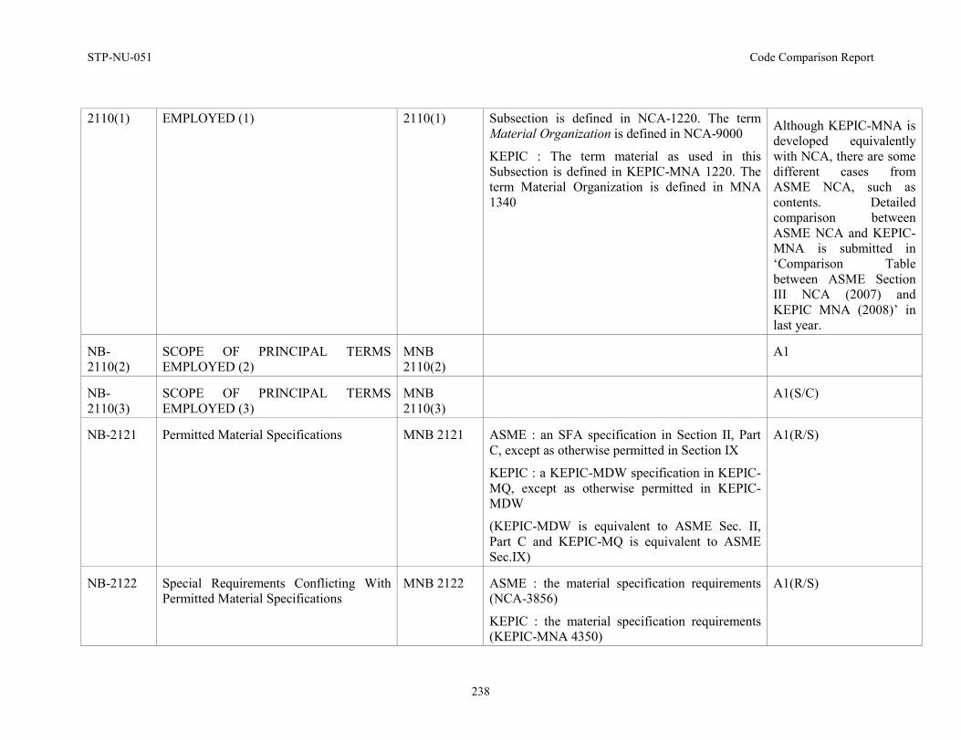
STP-NU-051 Code Comparison Report
238
2110(1) EMPLOYED (1) 2110(1) Subsection is defined in NCA-1220. The term Material Organization is defined in NCA-9000
KEPIC : The term material as used in this Subsection is defined in KEPIC-MNA 1220. The term Material Organization is defined in MNA 1340
Although KEPIC-MNA is developed equivalently with NCA, there are some different cases from ASME NCA, such as contents. Detailed comparison between ASME NCA and KEPIC-MNA is submitted in ‘Comparison Table between ASME Section III NCA (2007) and KEPIC MNA (2008)’ in last year.
NB-2110(2)
SCOPE OF PRINCIPAL TERMS EMPLOYED (2)
MNB 2110(2)
A1
NB-2110(3)
SCOPE OF PRINCIPAL TERMS EMPLOYED (3)
MNB 2110(3)
A1(S/C)
NB-2121 Permitted Material Specifications MNB 2121 ASME : an SFA specification in Section II, Part C, except as otherwise permitted in Section IX
KEPIC : a KEPIC-MDW specification in KEPIC-MQ, except as otherwise permitted in KEPIC-MDW
(KEPIC-MDW is equivalent to ASME Sec. II, Part C and KEPIC-MQ is equivalent to ASME Sec.IX)
A1(R/S)
NB-2122 Special Requirements Conflicting With Permitted Material Specifications
MNB 2122 ASME : the material specification requirements (NCA-3856)
KEPIC : the material specification requirements (KEPIC-MNA 4350)
A1(R/S)
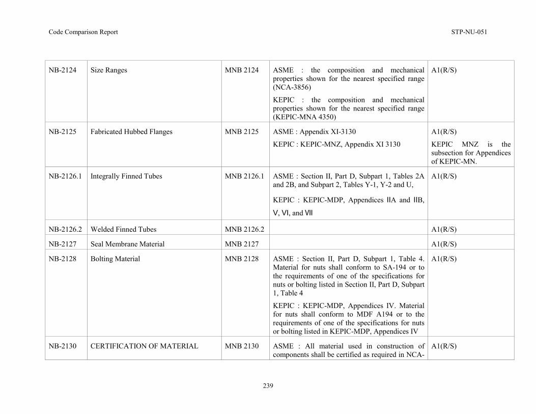
Code Comparison Report STP-NU-051
239
NB-2124 Size Ranges MNB 2124 ASME : the composition and mechanical properties shown for the nearest specified range (NCA-3856)
KEPIC : the composition and mechanical properties shown for the nearest specified range (KEPIC-MNA 4350)
A1(R/S)
NB-2125 Fabricated Hubbed Flanges MNB 2125 ASME : Appendix XI-3130
KEPIC : KEPIC-MNZ, Appendix XI 3130
A1(R/S)
KEPIC MNZ is the subsection for Appendices of KEPIC-MN.
NB-2126.1 Integrally Finned Tubes MNB 2126.1 ASME : Section II, Part D, Subpart 1, Tables 2A and 2B, and Subpart 2, Tables Y-1, Y-2 and U,
KEPIC : KEPIC-MDP, Appendices ⅡA and ⅡB,
Ⅴ, Ⅵ, and Ⅶ
A1(R/S)
NB-2126.2 Welded Finned Tubes MNB 2126.2 A1(R/S)
NB-2127 Seal Membrane Material MNB 2127 A1(R/S)
NB-2128 Bolting Material MNB 2128 ASME : Section II, Part D, Subpart 1, Table 4. Material for nuts shall conform to SA-194 or to the requirements of one of the specifications for nuts or bolting listed in Section II, Part D, Subpart 1, Table 4
KEPIC : KEPIC-MDP, Appendices IV. Material for nuts shall conform to MDF A194 or to the requirements of one of the specifications for nuts or bolting listed in KEPIC-MDP, Appendices IV
A1(R/S)
NB-2130 CERTIFICATION OF MATERIAL MNB 2130 ASME : All material used in construction of components shall be certified as required in NCA-
A1(R/S)
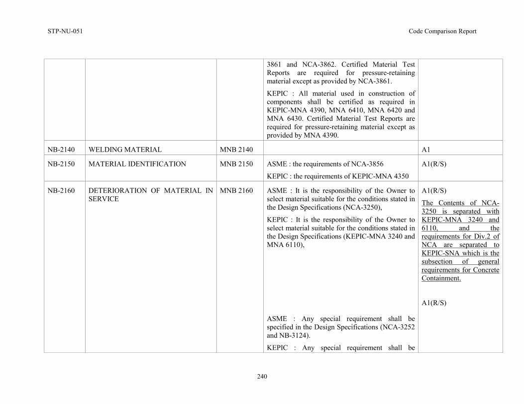
STP-NU-051 Code Comparison Report
240
3861 and NCA-3862. Certified Material Test Reports are required for pressure-retaining material except as provided by NCA-3861.
KEPIC : All material used in construction of components shall be certified as required in KEPIC-MNA 4390, MNA 6410, MNA 6420 and MNA 6430. Certified Material Test Reports are required for pressure-retaining material except as provided by MNA 4390.
NB-2140 WELDING MATERIAL MNB 2140 A1
NB-2150 MATERIAL IDENTIFICATION MNB 2150 ASME : the requirements of NCA-3856
KEPIC : the requirements of KEPIC-MNA 4350
A1(R/S)
NB-2160 DETERIORATION OF MATERIAL IN SERVICE
MNB 2160 ASME : It is the responsibility of the Owner to select material suitable for the conditions stated in the Design Specifications (NCA-3250),
KEPIC : It is the responsibility of the Owner to select material suitable for the conditions stated in the Design Specifications (KEPIC-MNA 3240 and MNA 6110),
ASME : Any special requirement shall be specified in the Design Specifications (NCA-3252 and NB-3124).
KEPIC : Any special requirement shall be
A1(R/S)
The Contents of NCA-3250 is separated with KEPIC-MNA 3240 and 6110, and the requirements for Div.2 of NCA are separated to KEPIC-SNA which is the subsection of general requirements for Concrete Containment.
A1(R/S)
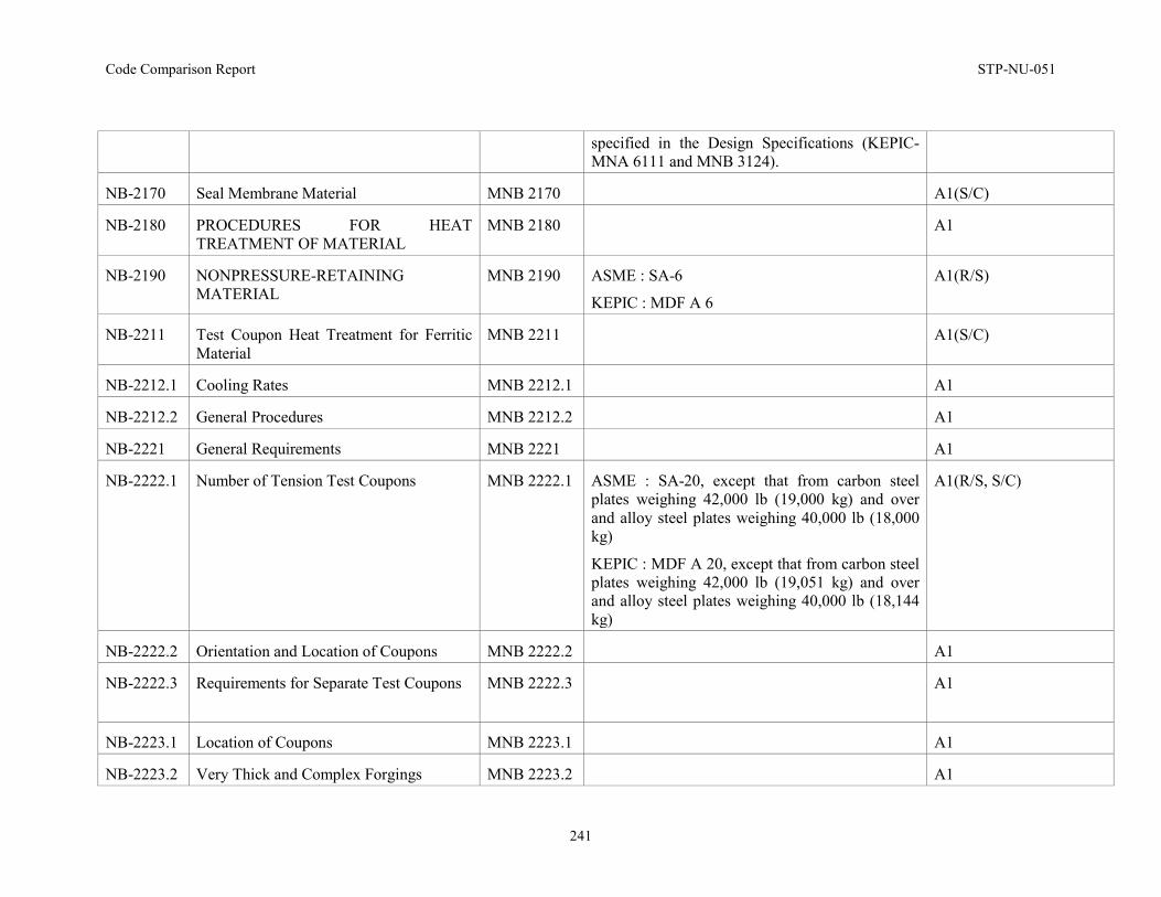
Code Comparison Report STP-NU-051
241
specified in the Design Specifications (KEPIC-MNA 6111 and MNB 3124).
NB-2170 Seal Membrane Material MNB 2170 A1(S/C)
NB-2180 PROCEDURES FOR HEAT TREATMENT OF MATERIAL
MNB 2180 A1
NB-2190 NONPRESSURE-RETAINING MATERIAL
MNB 2190 ASME : SA-6
KEPIC : MDF A 6
A1(R/S)
NB-2211 Test Coupon Heat Treatment for Ferritic Material
MNB 2211 A1(S/C)
NB-2212.1 Cooling Rates MNB 2212.1 A1
NB-2212.2 General Procedures MNB 2212.2 A1
NB-2221 General Requirements MNB 2221 A1
NB-2222.1 Number of Tension Test Coupons MNB 2222.1 ASME : SA-20, except that from carbon steel plates weighing 42,000 lb (19,000 kg) and over and alloy steel plates weighing 40,000 lb (18,000 kg)
KEPIC : MDF A 20, except that from carbon steel plates weighing 42,000 lb (19,051 kg) and over and alloy steel plates weighing 40,000 lb (18,144 kg)
A1(R/S, S/C)
NB-2222.2 Orientation and Location of Coupons MNB 2222.2 A1
NB-2222.3 Requirements for Separate Test Coupons MNB 2222.3 A1
NB-2223.1 Location of Coupons MNB 2223.1 A1
NB-2223.2 Very Thick and Complex Forgings MNB 2223.2 A1
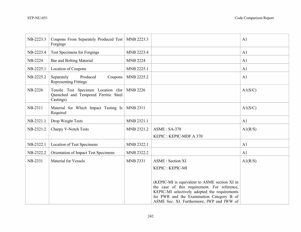
STP-NU-051 Code Comparison Report
242
NB-2223.3 Coupons From Separately Produced Test Forgings
MNB 2223.3 A1
NB-2223.4 Test Specimens for Forgings MNB 2223.4 A1
NB-2224 Bar and Bolting Material MNB 2224 A1
NB-2225.1 Location of Coupons MNB 2225.1 A1
NB-2225.2 Separately Produced Coupons Representing Fittings
MNB 2225.2 A1
NB-2226 Tensile Test Specimen Location (for Quenched and Tempered Ferritic Steel Castings)
MNB 2226 A1(S/C)
NB-2311 Material for Which Impact Testing Is Required
MNB 2311 A1(S/C)
NB-2321.1 Drop Weight Tests MNB 2321.1 A1
NB-2321.2 Charpy V-Notch Tests MNB 2321.2 ASME : SA-370
KEPIC : KEPIC-MDF A 370
A1(R/S)
NB-2322.1 Location of Test Specimens MNB 2322.1 A1
NB-2322.2 Orientation of Impact Test Specimens MNB 2322.2 A1
NB-2331 Material for Vessels MNB 2331 ASME : Section XI
KEPIC : KEPIC-MI
(KEPIC-MI is equivalent to ASME section XI in the case of this requirement. For reference, KEPIC-MI selectively adopted the requirements for PWR and the Examination Category B of ASME Sec. XI. Furthermore, IWP and IWW of
A1(R/S)
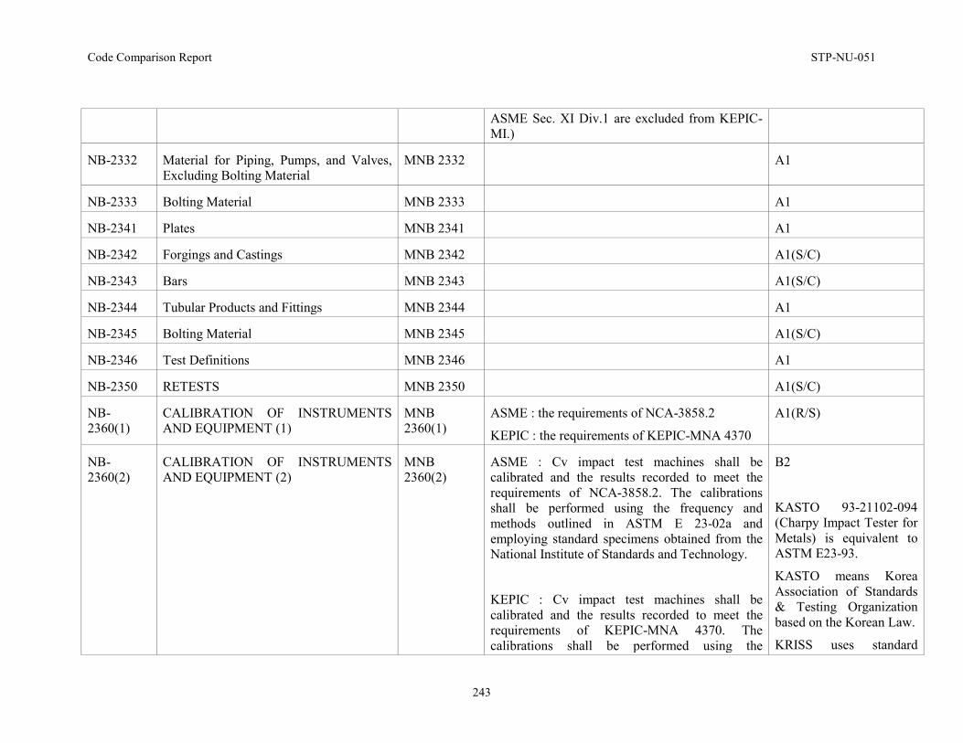
Code Comparison Report STP-NU-051
243
ASME Sec. XI Div.1 are excluded from KEPIC-MI.)
NB-2332 Material for Piping, Pumps, and Valves, Excluding Bolting Material
MNB 2332 A1
NB-2333 Bolting Material MNB 2333 A1
NB-2341 Plates MNB 2341 A1
NB-2342 Forgings and Castings MNB 2342 A1(S/C)
NB-2343 Bars MNB 2343 A1(S/C)
NB-2344 Tubular Products and Fittings MNB 2344 A1
NB-2345 Bolting Material MNB 2345 A1(S/C)
NB-2346 Test Definitions MNB 2346 A1
NB-2350 RETESTS MNB 2350 A1(S/C)
NB-2360(1)
CALIBRATION OF INSTRUMENTS AND EQUIPMENT (1)
MNB 2360(1)
ASME : the requirements of NCA-3858.2
KEPIC : the requirements of KEPIC-MNA 4370
A1(R/S)
NB-2360(2)
CALIBRATION OF INSTRUMENTS AND EQUIPMENT (2)
MNB 2360(2)
ASME : Cv impact test machines shall be calibrated and the results recorded to meet the requirements of NCA-3858.2. The calibrations shall be performed using the frequency and methods outlined in ASTM E 23-02a and employing standard specimens obtained from the National Institute of Standards and Technology.
KEPIC : Cv impact test machines shall be calibrated and the results recorded to meet the requirements of KEPIC-MNA 4370. The calibrations shall be performed using the
B2
KASTO 93-21102-094 (Charpy Impact Tester for Metals) is equivalent to ASTM E23-93.
KASTO means Korea Association of Standards & Testing Organization based on the Korean Law.
KRISS uses standard
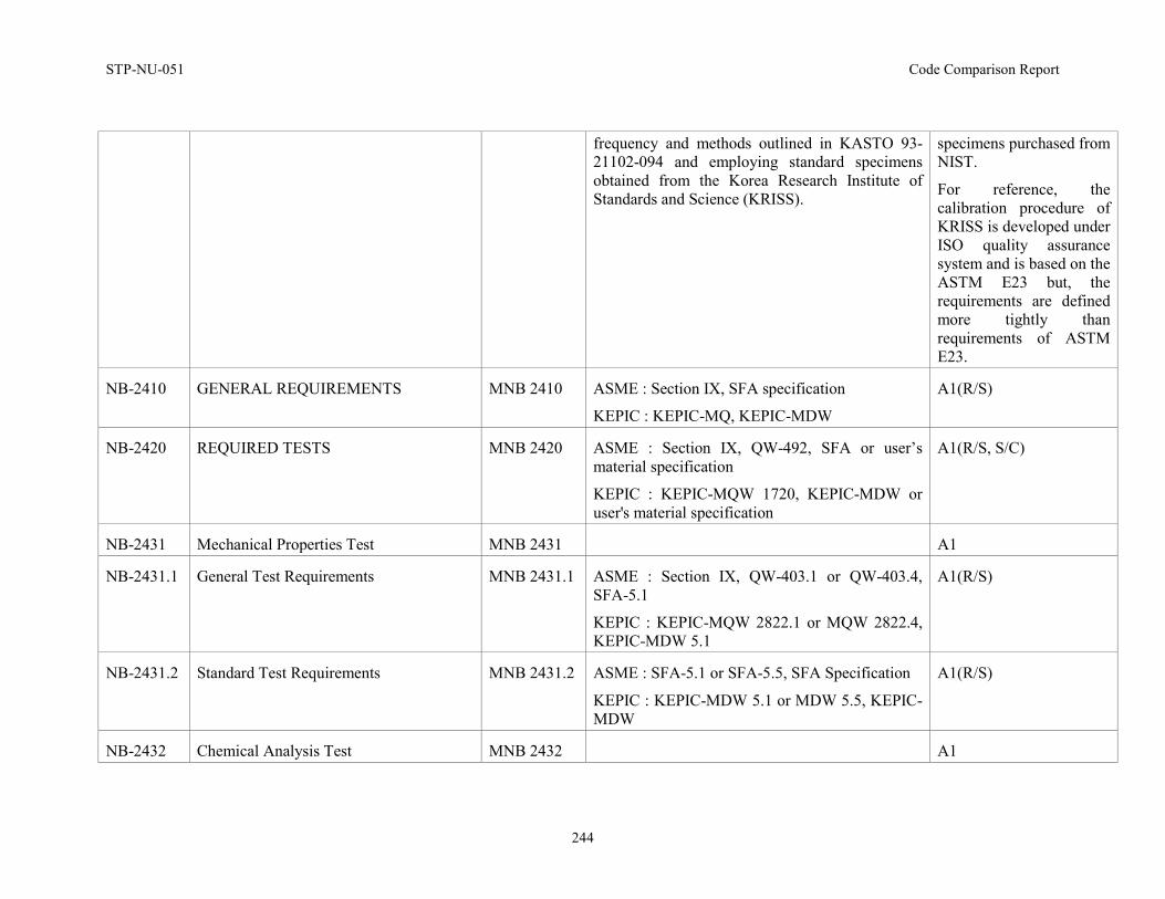
STP-NU-051 Code Comparison Report
244
frequency and methods outlined in KASTO 93-21102-094 and employing standard specimens obtained from the Korea Research Institute of Standards and Science (KRISS).
specimens purchased from NIST.
For reference, the calibration procedure of KRISS is developed under ISO quality assurance system and is based on the ASTM E23 but, the requirements are defined more tightly than requirements of ASTM E23.
NB-2410 GENERAL REQUIREMENTS
MNB 2410 ASME : Section IX, SFA specification
KEPIC : KEPIC-MQ, KEPIC-MDW
A1(R/S)
NB-2420 REQUIRED TESTS
MNB 2420 ASME : Section IX, QW-492, SFA or user’s material specification
KEPIC : KEPIC-MQW 1720, KEPIC-MDW or user's material specification
A1(R/S, S/C)
NB-2431 Mechanical Properties Test MNB 2431 A1
NB-2431.1 General Test Requirements
MNB 2431.1 ASME : Section IX, QW-403.1 or QW-403.4, SFA-5.1
KEPIC : KEPIC-MQW 2822.1 or MQW 2822.4, KEPIC-MDW 5.1
A1(R/S)
NB-2431.2 Standard Test Requirements
MNB 2431.2 ASME : SFA-5.1 or SFA-5.5, SFA Specification
KEPIC : KEPIC-MDW 5.1 or MDW 5.5, KEPIC-MDW
A1(R/S)
NB-2432 Chemical Analysis Test MNB 2432 A1
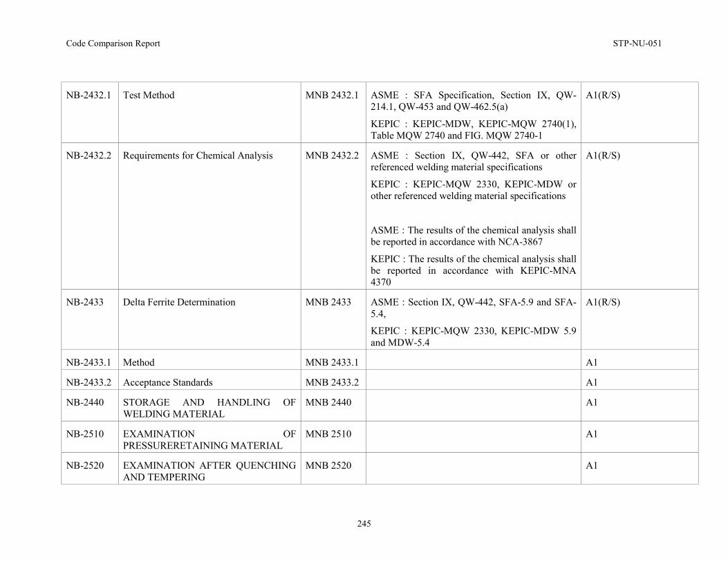
Code Comparison Report STP-NU-051
245
NB-2432.1 Test Method
MNB 2432.1 ASME : SFA Specification, Section IX, QW-214.1, QW-453 and QW-462.5(a)
KEPIC : KEPIC-MDW, KEPIC-MQW 2740(1), Table MQW 2740 and FIG. MQW 2740-1
A1(R/S)
NB-2432.2 Requirements for Chemical Analysis
MNB 2432.2 ASME : Section IX, QW-442, SFA or other referenced welding material specifications
KEPIC : KEPIC-MQW 2330, KEPIC-MDW or other referenced welding material specifications
ASME : The results of the chemical analysis shall be reported in accordance with NCA-3867
KEPIC : The results of the chemical analysis shall be reported in accordance with KEPIC-MNA 4370
A1(R/S)
NB-2433 Delta Ferrite Determination
MNB 2433 ASME : Section IX, QW-442, SFA-5.9 and SFA-5.4,
KEPIC : KEPIC-MQW 2330, KEPIC-MDW 5.9 and MDW-5.4
A1(R/S)
NB-2433.1 Method MNB 2433.1 A1
NB-2433.2 Acceptance Standards MNB 2433.2 A1
NB-2440 STORAGE AND HANDLING OF WELDING MATERIAL
MNB 2440 A1
NB-2510 EXAMINATION OF PRESSURERETAINING MATERIAL
MNB 2510 A1
NB-2520 EXAMINATION AFTER QUENCHING AND TEMPERING
MNB 2520 A1
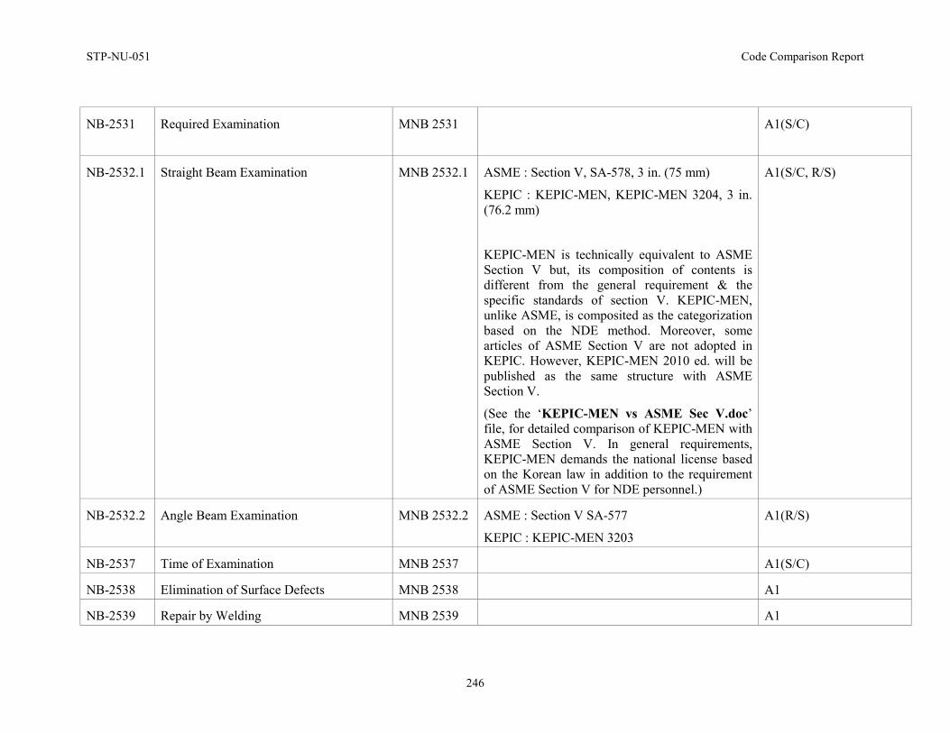
STP-NU-051 Code Comparison Report
246
NB-2531 Required Examination
MNB 2531 A1(S/C)
NB-2532.1 Straight Beam Examination MNB 2532.1 ASME : Section V, SA-578, 3 in. (75 mm)
KEPIC : KEPIC-MEN, KEPIC-MEN 3204, 3 in. (76.2 mm)
KEPIC-MEN is technically equivalent to ASME Section V but, its composition of contents is different from the general requirement & the specific standards of section V. KEPIC-MEN, unlike ASME, is composited as the categorization based on the NDE method. Moreover, some articles of ASME Section V are not adopted in KEPIC. However, KEPIC-MEN 2010 ed. will be published as the same structure with ASME Section V.
(See the ‘KEPIC-MEN vs ASME Sec V.doc’ file, for detailed comparison of KEPIC-MEN with ASME Section V. In general requirements, KEPIC-MEN demands the national license based on the Korean law in addition to the requirement of ASME Section V for NDE personnel.)
A1(S/C, R/S)
NB-2532.2 Angle Beam Examination MNB 2532.2 ASME : Section V SA-577
KEPIC : KEPIC-MEN 3203
A1(R/S)
NB-2537 Time of Examination MNB 2537 A1(S/C)
NB-2538 Elimination of Surface Defects MNB 2538 A1
NB-2539 Repair by Welding MNB 2539 A1
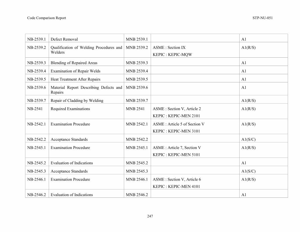
Code Comparison Report STP-NU-051
247
NB-2539.1 Defect Removal MNB 2539.1 A1
NB-2539.2 Qualification of Welding Procedures and Welders
MNB 2539.2 ASME : Section IX
KEPIC : KEPIC-MQW
A1(R/S)
NB-2539.3 Blending of Repaired Areas MNB 2539.3 A1
NB-2539.4 Examination of Repair Welds MNB 2539.4 A1
NB-2539.5 Heat Treatment After Repairs MNB 2539.5 A1
NB-2539.6 Material Report Describing Defects and Repairs
MNB 2539.6 A1
NB-2539.7 Repair of Cladding by Welding MNB 2539.7 A1(R/S)
NB-2541 Required Examinations MNB 2541 ASME : Section V, Article 2
KEPIC : KEPIC-MEN 2101
A1(R/S)
NB-2542.1 Examination Procedure MNB 2542.1 ASME : Article 5 of Section V
KEPIC : KEPIC-MEN 3101
A1(R/S)
NB-2542.2 Acceptance Standards MNB 2542.2 A1(S/C)
NB-2545.1 Examination Procedure MNB 2545.1 ASME : Article 7, Section V
KEPIC : KEPIC-MEN 5101
A1(R/S)
NB-2545.2 Evaluation of Indications MNB 2545.2 A1
NB-2545.3 Acceptance Standards MNB 2545.3 A1(S/C)
NB-2546.1 Examination Procedure MNB 2546.1 ASME : Section V, Article 6
KEPIC : KEPIC-MEN 4101
A1(R/S)
NB-2546.2 Evaluation of Indications MNB 2546.2 A1
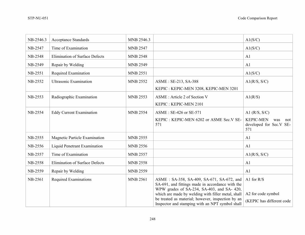
STP-NU-051 Code Comparison Report
248
NB-2546.3 Acceptance Standards MNB 2546.3 A1(S/C)
NB-2547 Time of Examination MNB 2547 A1(S/C)
NB-2548 Elimination of Surface Defects MNB 2548 A1
NB-2549 Repair by Welding MNB 2549 A1
NB-2551 Required Examination MNB 2551 A1(S/C)
NB-2552 Ultrasonic Examination MNB 2552 ASME : SE-213, SA-388
KEPIC : KEPIC-MEN 3208, KEPIC-MEN 3201
A1(R/S, S/C)
NB-2553 Radiographic Examination MNB 2553 ASME : Article 2 of Section V
KEPIC : KEPIC-MEN 2101
A1(R/S)
NB-2554 Eddy Current Examination MNB 2554 ASME : SE-426 or SE-571
KEPIC : KEPIC-MEN 6202 or ASME Sec.V SE-571
A1 (R/S, S/C)
KEPIC-MEN was not developed for Sec.V SE-571
NB-2555 Magnetic Particle Examination MNB 2555 A1
NB-2556 Liquid Penetrant Examination MNB 2556 A1
NB-2557 Time of Examination MNB 2557 A1(R/S, S/C)
NB-2558 Elimination of Surface Defects MNB 2558 A1
NB-2559 Repair by Welding MNB 2559 A1
NB-2561 Required Examinations
MNB 2561 ASME : SA-358, SA-409, SA-671, SA-672, and SA-691, and fittings made in accordance with the WPW grades of SA-234, SA-403, and SA- 420, which are made by welding with filler metal, shall be treated as material; however, inspection by an Inspector and stamping with an NPT symbol shall
A1 for R/S
A2 for code symbol
(KEPIC has different code
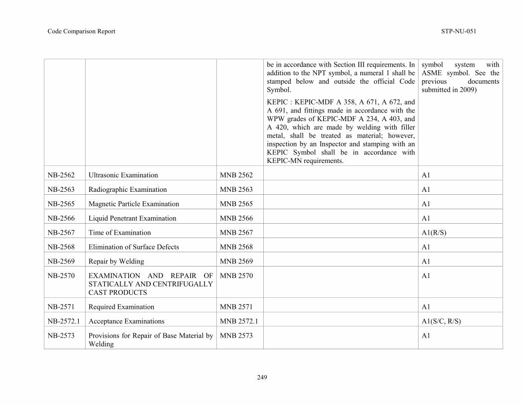
Code Comparison Report STP-NU-051
249
be in accordance with Section III requirements. In addition to the NPT symbol, a numeral 1 shall be stamped below and outside the official Code Symbol.
KEPIC : KEPIC-MDF A 358, A 671, A 672, and A 691, and fittings made in accordance with the WPW grades of KEPIC-MDF A 234, A 403, and A 420, which are made by welding with filler metal, shall be treated as material; however, inspection by an Inspector and stamping with an KEPIC Symbol shall be in accordance with KEPIC-MN requirements.
symbol system with ASME symbol. See the previous documents submitted in 2009)
NB-2562 Ultrasonic Examination MNB 2562 A1
NB-2563 Radiographic Examination MNB 2563 A1
NB-2565 Magnetic Particle Examination MNB 2565 A1
NB-2566 Liquid Penetrant Examination MNB 2566 A1
NB-2567 Time of Examination MNB 2567 A1(R/S)
NB-2568 Elimination of Surface Defects MNB 2568 A1
NB-2569 Repair by Welding MNB 2569 A1
NB-2570 EXAMINATION AND REPAIR OF STATICALLY AND CENTRIFUGALLY CAST PRODUCTS
MNB 2570 A1
NB-2571 Required Examination MNB 2571 A1
NB-2572.1 Acceptance Examinations MNB 2572.1 A1(S/C, R/S)
NB-2573 Provisions for Repair of Base Material by Welding
MNB 2573 A1
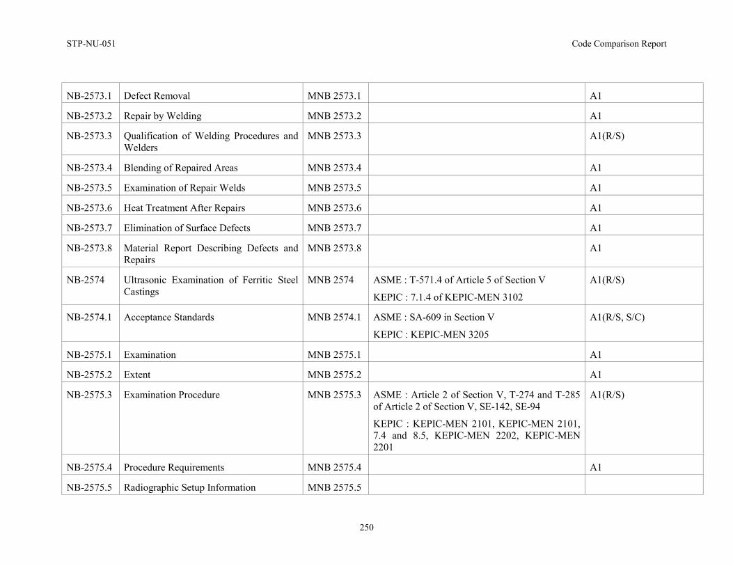
STP-NU-051 Code Comparison Report
250
NB-2573.1 Defect Removal MNB 2573.1 A1
NB-2573.2 Repair by Welding MNB 2573.2 A1
NB-2573.3 Qualification of Welding Procedures and Welders
MNB 2573.3 A1(R/S)
NB-2573.4 Blending of Repaired Areas MNB 2573.4 A1
NB-2573.5 Examination of Repair Welds MNB 2573.5 A1
NB-2573.6 Heat Treatment After Repairs MNB 2573.6 A1
NB-2573.7 Elimination of Surface Defects MNB 2573.7 A1
NB-2573.8 Material Report Describing Defects and Repairs
MNB 2573.8 A1
NB-2574 Ultrasonic Examination of Ferritic Steel Castings
MNB 2574 ASME : T-571.4 of Article 5 of Section V
KEPIC : 7.1.4 of KEPIC-MEN 3102
A1(R/S)
NB-2574.1 Acceptance Standards MNB 2574.1 ASME : SA-609 in Section V
KEPIC : KEPIC-MEN 3205
A1(R/S, S/C)
NB-2575.1 Examination MNB 2575.1 A1
NB-2575.2 Extent MNB 2575.2 A1
NB-2575.3 Examination Procedure
MNB 2575.3 ASME : Article 2 of Section V, T-274 and T-285 of Article 2 of Section V, SE-142, SE-94
KEPIC : KEPIC-MEN 2101, KEPIC-MEN 2101, 7.4 and 8.5, KEPIC-MEN 2202, KEPIC-MEN 2201
A1(R/S)
NB-2575.4 Procedure Requirements MNB 2575.4 A1
NB-2575.5 Radiographic Setup Information MNB 2575.5
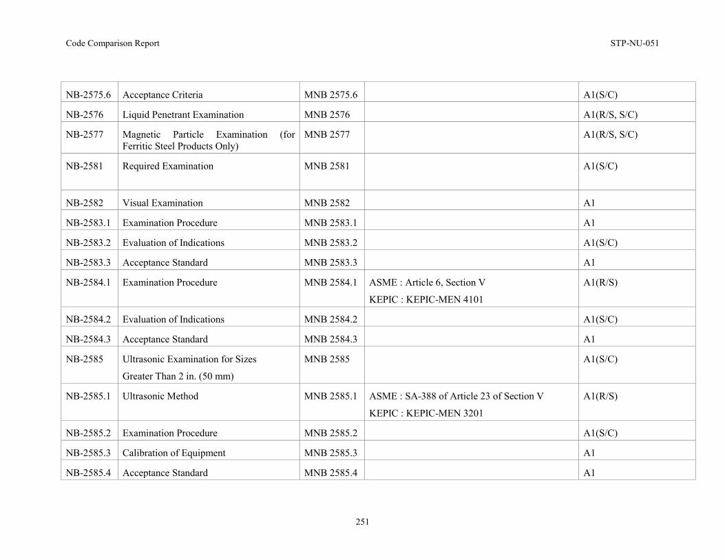
Code Comparison Report STP-NU-051
251
NB-2575.6 Acceptance Criteria MNB 2575.6 A1(S/C)
NB-2576 Liquid Penetrant Examination MNB 2576 A1(R/S, S/C)
NB-2577 Magnetic Particle Examination (for Ferritic Steel Products Only)
MNB 2577 A1(R/S, S/C)
NB-2581 Required Examination
MNB 2581 A1(S/C)
NB-2582 Visual Examination MNB 2582 A1
NB-2583.1 Examination Procedure MNB 2583.1 A1
NB-2583.2 Evaluation of Indications MNB 2583.2 A1(S/C)
NB-2583.3 Acceptance Standard MNB 2583.3 A1
NB-2584.1 Examination Procedure MNB 2584.1 ASME : Article 6, Section V
KEPIC : KEPIC-MEN 4101
A1(R/S)
NB-2584.2 Evaluation of Indications MNB 2584.2 A1(S/C)
NB-2584.3 Acceptance Standard MNB 2584.3 A1
NB-2585 Ultrasonic Examination for Sizes
Greater Than 2 in. (50 mm)
MNB 2585 A1(S/C)
NB-2585.1 Ultrasonic Method MNB 2585.1 ASME : SA-388 of Article 23 of Section V
KEPIC : KEPIC-MEN 3201
A1(R/S)
NB-2585.2 Examination Procedure MNB 2585.2 A1(S/C)
NB-2585.3 Calibration of Equipment MNB 2585.3 A1
NB-2585.4 Acceptance Standard MNB 2585.4 A1
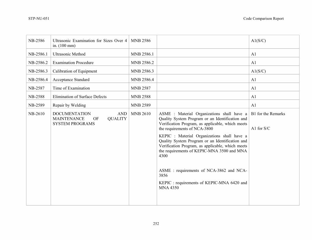
STP-NU-051 Code Comparison Report
252
NB-2586 Ultrasonic Examination for Sizes Over 4 in. (100 mm)
MNB 2586 A1(S/C)
NB-2586.1 Ultrasonic Method MNB 2586.1 A1
NB-2586.2 Examination Procedure MNB 2586.2 A1
NB-2586.3 Calibration of Equipment MNB 2586.3 A1(S/C)
NB-2586.4 Acceptance Standard MNB 2586.4 A1
NB-2587 Time of Examination MNB 2587 A1
NB-2588 Elimination of Surface Defects MNB 2588 A1
NB-2589 Repair by Welding MNB 2589 A1
NB-2610 DOCUMENTATION AND MAINTENANCE OF QUALITY SYSTEM PROGRAMS
MNB 2610 ASME : Material Organizations shall have a Quality System Program or an Identification and Verification Program, as applicable, which meets the requirements of NCA-3800
KEPIC : Material Organizations shall have a Quality System Program or an Identification and Verification Program, as applicable, which meets the requirements of KEPIC-MNA 3500 and MNA 4300
ASME : requirements of NCA-3862 and NCA-3856
KEPIC : requirements of KEPIC-MNA 6420 and MNA 4350
B1 for the Remarks
A1 for S/C
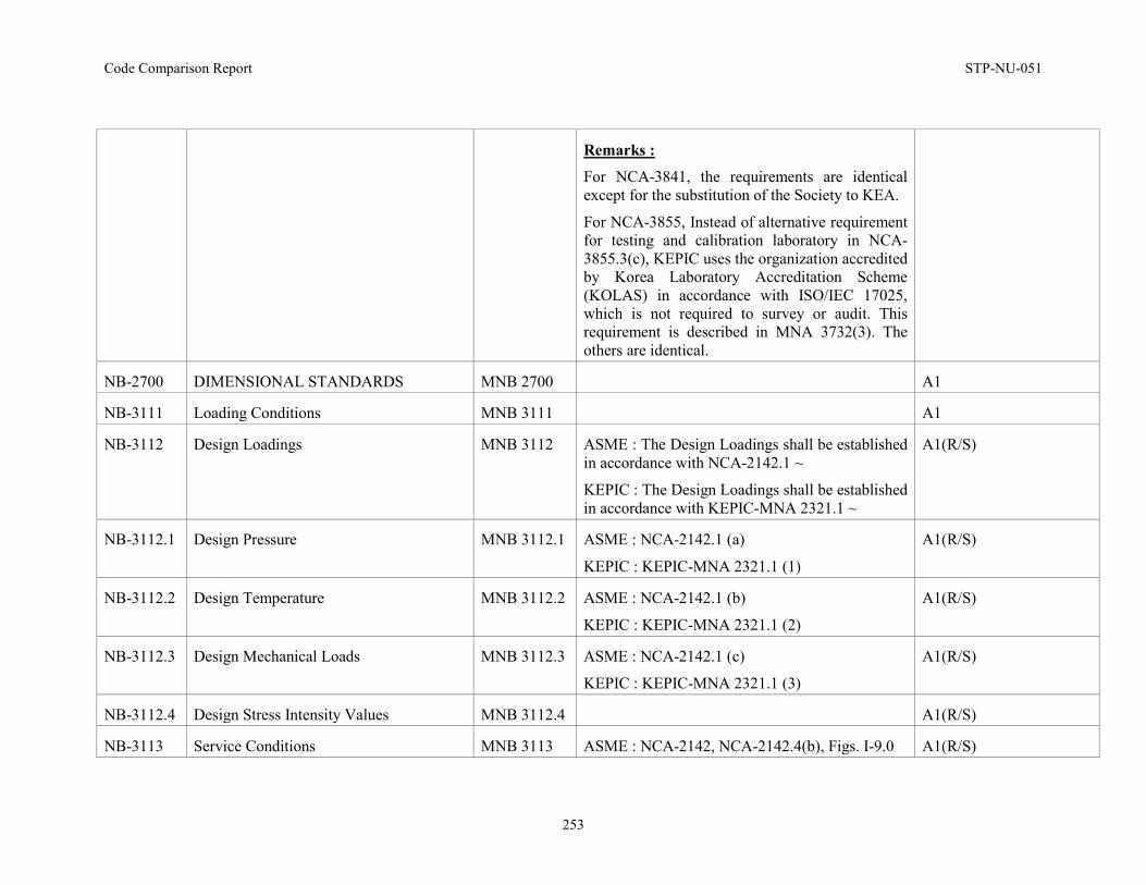
Code Comparison Report STP-NU-051
253
Remarks :
For NCA-3841, the requirements are identical except for the substitution of the Society to KEA.
For NCA-3855, Instead of alternative requirement for testing and calibration laboratory in NCA-3855.3(c), KEPIC uses the organization accredited by Korea Laboratory Accreditation Scheme (KOLAS) in accordance with ISO/IEC 17025, which is not required to survey or audit. This requirement is described in MNA 3732(3). The others are identical.
NB-2700 DIMENSIONAL STANDARDS MNB 2700 A1
NB-3111 Loading Conditions MNB 3111 A1
NB-3112 Design Loadings MNB 3112 ASME : The Design Loadings shall be established in accordance with NCA-2142.1 ~
KEPIC : The Design Loadings shall be established in accordance with KEPIC-MNA 2321.1 ~
A1(R/S)
NB-3112.1 Design Pressure MNB 3112.1 ASME : NCA-2142.1 (a)
KEPIC : KEPIC-MNA 2321.1 (1)
A1(R/S)
NB-3112.2 Design Temperature MNB 3112.2 ASME : NCA-2142.1 (b)
KEPIC : KEPIC-MNA 2321.1 (2)
A1(R/S)
NB-3112.3 Design Mechanical Loads MNB 3112.3 ASME : NCA-2142.1 (c)
KEPIC : KEPIC-MNA 2321.1 (3)
A1(R/S)
NB-3112.4 Design Stress Intensity Values MNB 3112.4 A1(R/S)
NB-3113 Service Conditions MNB 3113 ASME : NCA-2142, NCA-2142.4(b), Figs. I-9.0 A1(R/S)
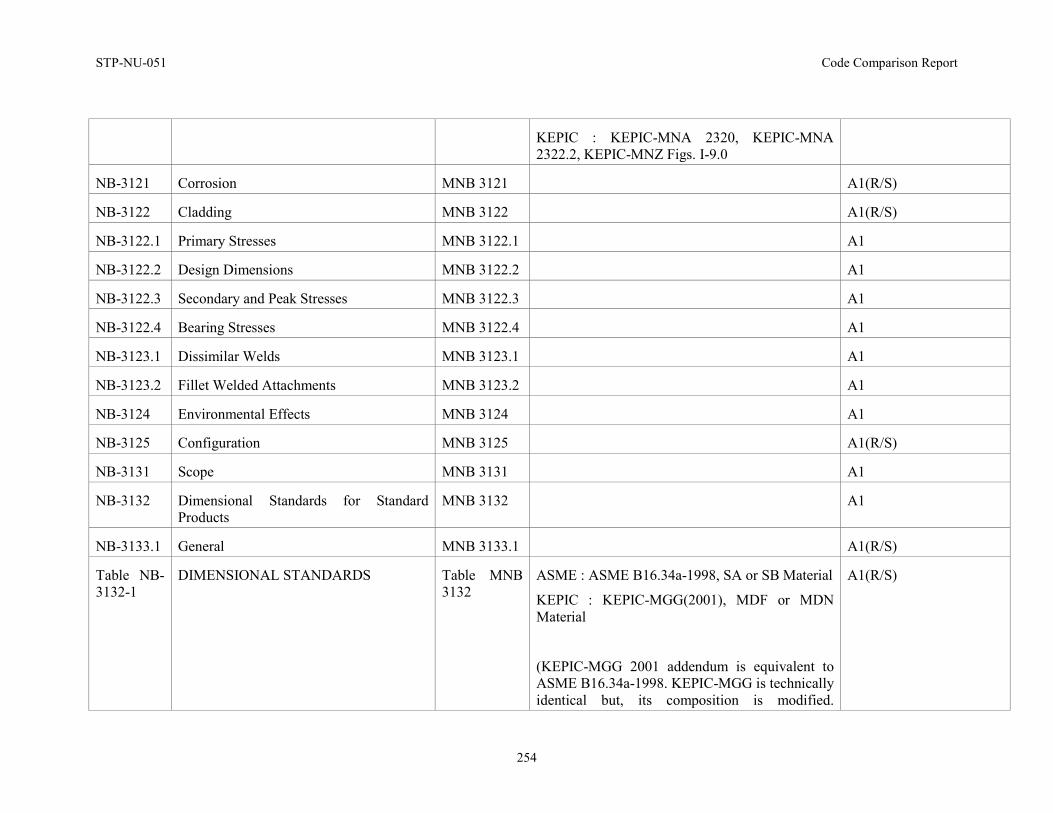
STP-NU-051 Code Comparison Report
254
KEPIC : KEPIC-MNA 2320, KEPIC-MNA 2322.2, KEPIC-MNZ Figs. I-9.0
NB-3121 Corrosion MNB 3121 A1(R/S)
NB-3122 Cladding MNB 3122 A1(R/S)
NB-3122.1 Primary Stresses MNB 3122.1 A1
NB-3122.2 Design Dimensions MNB 3122.2 A1
NB-3122.3 Secondary and Peak Stresses MNB 3122.3 A1
NB-3122.4 Bearing Stresses MNB 3122.4 A1
NB-3123.1 Dissimilar Welds MNB 3123.1 A1
NB-3123.2 Fillet Welded Attachments MNB 3123.2 A1
NB-3124 Environmental Effects MNB 3124 A1
NB-3125 Configuration MNB 3125 A1(R/S)
NB-3131 Scope MNB 3131 A1
NB-3132 Dimensional Standards for Standard Products
MNB 3132 A1
NB-3133.1 General MNB 3133.1 A1(R/S)
Table NB-3132-1
DIMENSIONAL STANDARDS
Table MNB 3132
ASME : ASME B16.34a-1998, SA or SB Material
KEPIC : KEPIC-MGG(2001), MDF or MDN Material
(KEPIC-MGG 2001 addendum is equivalent to ASME B16.34a-1998. KEPIC-MGG is technically identical but, its composition is modified.
A1(R/S)
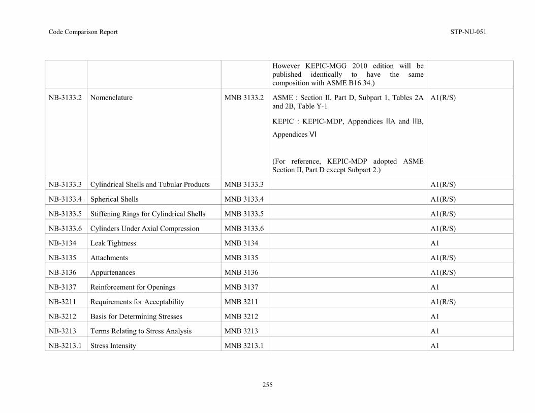
Code Comparison Report STP-NU-051
255
However KEPIC-MGG 2010 edition will be published identically to have the same composition with ASME B16.34.)
NB-3133.2 Nomenclature
MNB 3133.2 ASME : Section II, Part D, Subpart 1, Tables 2A and 2B, Table Y-1
KEPIC : KEPIC-MDP, Appendices ⅡA and ⅡB,
Appendices Ⅵ
(For reference, KEPIC-MDP adopted ASME Section II, Part D except Subpart 2.)
A1(R/S)
NB-3133.3 Cylindrical Shells and Tubular Products MNB 3133.3 A1(R/S)
NB-3133.4 Spherical Shells MNB 3133.4 A1(R/S)
NB-3133.5 Stiffening Rings for Cylindrical Shells MNB 3133.5 A1(R/S)
NB-3133.6 Cylinders Under Axial Compression MNB 3133.6 A1(R/S)
NB-3134 Leak Tightness MNB 3134 A1
NB-3135 Attachments MNB 3135 A1(R/S)
NB-3136 Appurtenances MNB 3136 A1(R/S)
NB-3137 Reinforcement for Openings MNB 3137 A1
NB-3211 Requirements for Acceptability MNB 3211 A1(R/S)
NB-3212 Basis for Determining Stresses MNB 3212 A1
NB-3213 Terms Relating to Stress Analysis MNB 3213 A1
NB-3213.1 Stress Intensity MNB 3213.1 A1
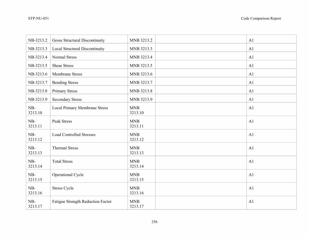
STP-NU-051 Code Comparison Report
256
NB-3213.2 Gross Structural Discontinuity MNB 3213.2 A1
NB-3213.3 Local Structural Discontinuity MNB 3213.3 A1
NB-3213.4 Normal Stress MNB 3213.4 A1
NB-3213.5 Shear Stress MNB 3213.5 A1
NB-3213.6 Membrane Stress MNB 3213.6 A1
NB-3213.7 Bending Stress MNB 3213.7 A1
NB-3213.8 Primary Stress MNB 3213.8 A1
NB-3213.9 Secondary Stress MNB 3213.9 A1
NB-3213.10
Local Primary Membrane Stress MNB 3213.10
A1
NB-3213.11
Peak Stress MNB 3213.11
A1
NB-3213.12
Load Controlled Stresses MNB 3213.12
A1
NB-3213.13
Thermal Stress MNB 3213.13
A1
NB-3213.14
Total Stress MNB 3213.14
A1
NB-3213.15
Operational Cycle MNB 3213.15
A1
NB-3213.16
Stress Cycle MNB 3213.16
A1
NB-3213.17
Fatigue Strength Reduction Factor MNB 3213.17
A1
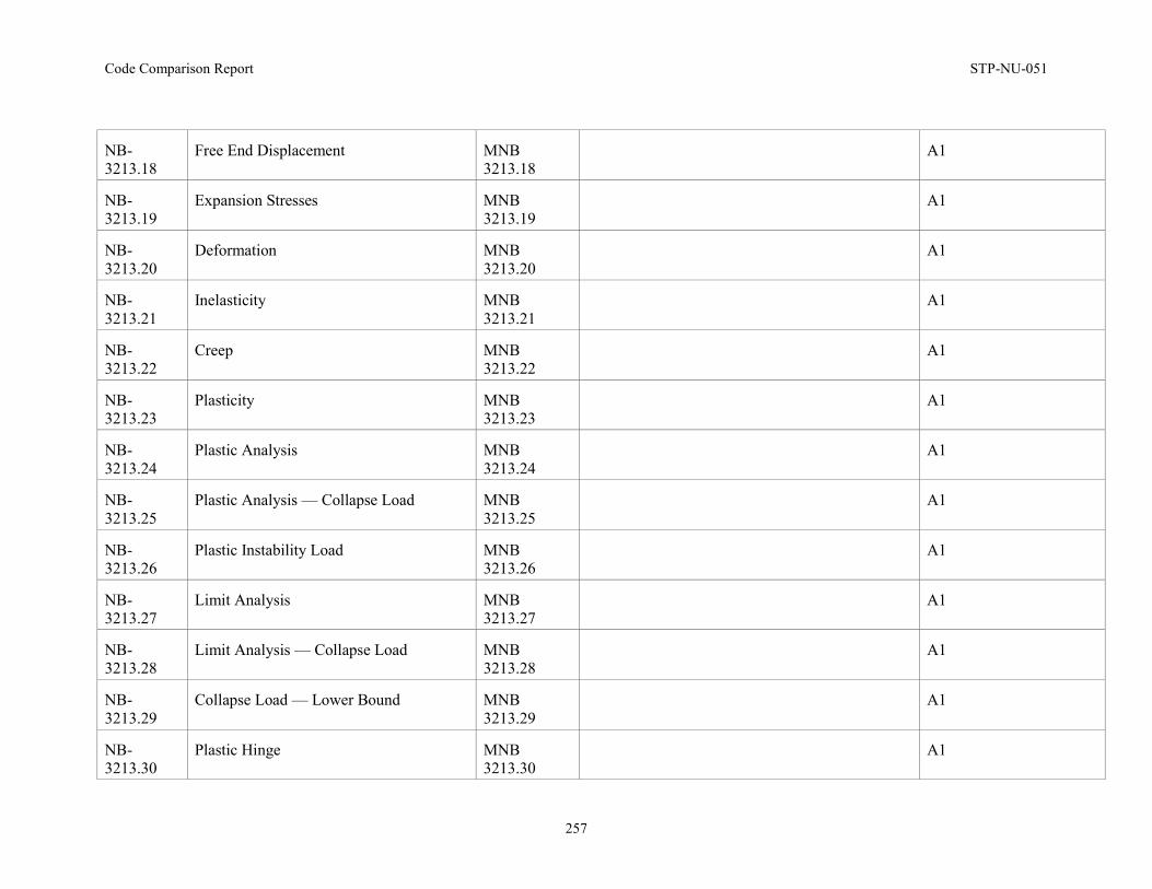
Code Comparison Report STP-NU-051
257
NB-3213.18
Free End Displacement MNB 3213.18
A1
NB-3213.19
Expansion Stresses MNB 3213.19
A1
NB-3213.20
Deformation MNB 3213.20
A1
NB-3213.21
Inelasticity MNB 3213.21
A1
NB-3213.22
Creep MNB 3213.22
A1
NB-3213.23
Plasticity MNB 3213.23
A1
NB-3213.24
Plastic Analysis MNB 3213.24
A1
NB-3213.25
Plastic Analysis — Collapse Load MNB 3213.25
A1
NB-3213.26
Plastic Instability Load MNB 3213.26
A1
NB-3213.27
Limit Analysis MNB 3213.27
A1
NB-3213.28
Limit Analysis — Collapse Load MNB 3213.28
A1
NB-3213.29
Collapse Load — Lower Bound MNB 3213.29
A1
NB-3213.30
Plastic Hinge MNB 3213.30
A1
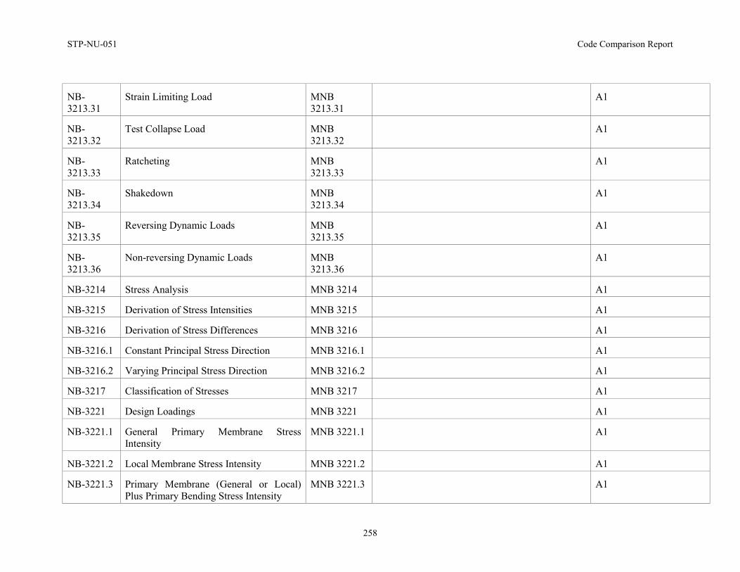
STP-NU-051 Code Comparison Report
258
NB-3213.31
Strain Limiting Load MNB 3213.31
A1
NB-3213.32
Test Collapse Load MNB 3213.32
A1
NB-3213.33
Ratcheting MNB 3213.33
A1
NB-3213.34
Shakedown MNB 3213.34
A1
NB-3213.35
Reversing Dynamic Loads MNB 3213.35
A1
NB-3213.36
Non-reversing Dynamic Loads MNB 3213.36
A1
NB-3214 Stress Analysis MNB 3214 A1
NB-3215 Derivation of Stress Intensities MNB 3215 A1
NB-3216 Derivation of Stress Differences MNB 3216 A1
NB-3216.1 Constant Principal Stress Direction MNB 3216.1 A1
NB-3216.2 Varying Principal Stress Direction MNB 3216.2 A1
NB-3217 Classification of Stresses MNB 3217 A1
NB-3221 Design Loadings MNB 3221 A1
NB-3221.1 General Primary Membrane Stress Intensity
MNB 3221.1 A1
NB-3221.2 Local Membrane Stress Intensity MNB 3221.2 A1
NB-3221.3 Primary Membrane (General or Local) Plus Primary Bending Stress Intensity
MNB 3221.3 A1
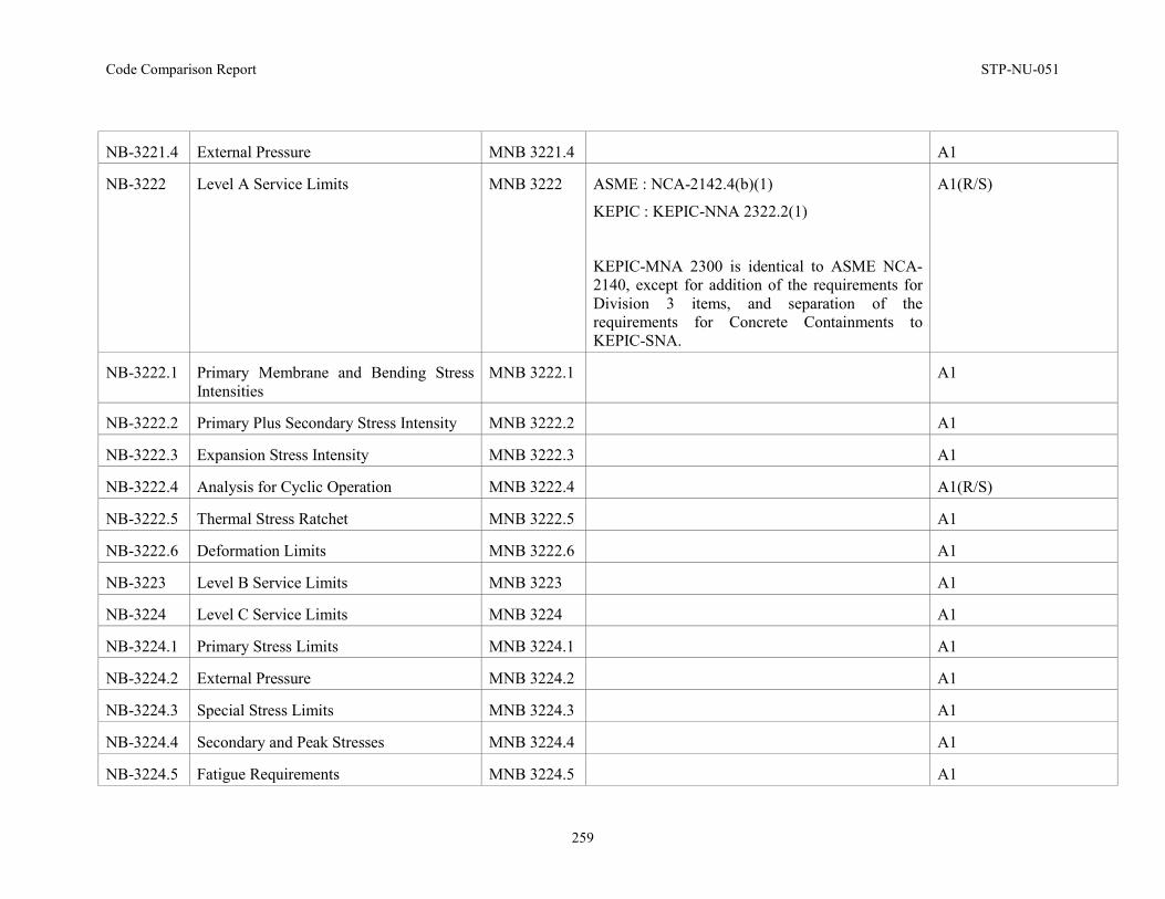
Code Comparison Report STP-NU-051
259
NB-3221.4 External Pressure MNB 3221.4 A1
NB-3222 Level A Service Limits MNB 3222 ASME : NCA-2142.4(b)(1)
KEPIC : KEPIC-NNA 2322.2(1)
KEPIC-MNA 2300 is identical to ASME NCA-2140, except for addition of the requirements for Division 3 items, and separation of the requirements for Concrete Containments to KEPIC-SNA.
A1(R/S)
NB-3222.1 Primary Membrane and Bending Stress Intensities
MNB 3222.1 A1
NB-3222.2 Primary Plus Secondary Stress Intensity MNB 3222.2 A1
NB-3222.3 Expansion Stress Intensity MNB 3222.3 A1
NB-3222.4 Analysis for Cyclic Operation MNB 3222.4 A1(R/S)
NB-3222.5 Thermal Stress Ratchet MNB 3222.5 A1
NB-3222.6 Deformation Limits MNB 3222.6 A1
NB-3223 Level B Service Limits MNB 3223 A1
NB-3224 Level C Service Limits MNB 3224 A1
NB-3224.1 Primary Stress Limits MNB 3224.1 A1
NB-3224.2 External Pressure MNB 3224.2 A1
NB-3224.3 Special Stress Limits MNB 3224.3 A1
NB-3224.4 Secondary and Peak Stresses MNB 3224.4 A1
NB-3224.5 Fatigue Requirements MNB 3224.5 A1
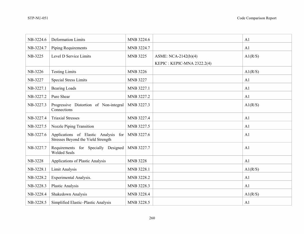
STP-NU-051 Code Comparison Report
260
NB-3224.6 Deformation Limits MNB 3224.6 A1
NB-3224.7 Piping Requirements MNB 3224.7 A1
NB-3225 Level D Service Limits MNB 3225 ASME: NCA-2142(b)(4)
KEPIC : KEPIC-MNA 2322.2(4)
A1(R/S)
NB-3226 Testing Limits MNB 3226 A1(R/S)
NB-3227 Special Stress Limits MNB 3227 A1
NB-3227.1 Bearing Loads MNB 3227.1 A1
NB-3227.2 Pure Shear MNB 3227.2 A1
NB-3227.3 Progressive Distortion of Non-integral Connections
MNB 3227.3 A1(R/S)
NB-3227.4 Triaxial Stresses MNB 3227.4 A1
NB-3227.5 Nozzle Piping Transition MNB 3227.5 A1
NB-3227.6 Applications of Elastic Analysis for Stresses Beyond the Yield Strength
MNB 3227.6 A1
NB-3227.7 Requirements for Specially Designed Welded Seals
MNB 3227.7 A1
NB-3228 Applications of Plastic Analysis MNB 3228 A1
NB-3228.1 Limit Analysis MNB 3228.1 A1(R/S)
NB-3228.2 Experimental Analysis. MNB 3228.2 A1
NB-3228.3 Plastic Analysis MNB 3228.3 A1
NB-3228.4 Shakedown Analysis MNB 3228.4 A1(R/S)
NB-3228.5 Simplified Elastic–Plastic Analysis MNB 3228.5 A1
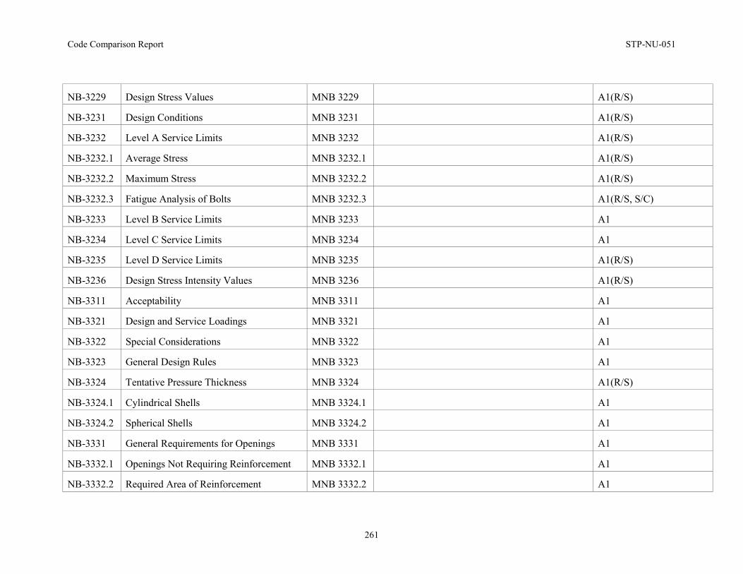
Code Comparison Report STP-NU-051
261
NB-3229 Design Stress Values MNB 3229 A1(R/S)
NB-3231 Design Conditions MNB 3231 A1(R/S)
NB-3232 Level A Service Limits MNB 3232 A1(R/S)
NB-3232.1 Average Stress MNB 3232.1 A1(R/S)
NB-3232.2 Maximum Stress MNB 3232.2 A1(R/S)
NB-3232.3 Fatigue Analysis of Bolts MNB 3232.3 A1(R/S, S/C)
NB-3233 Level B Service Limits MNB 3233 A1
NB-3234 Level C Service Limits MNB 3234 A1
NB-3235 Level D Service Limits MNB 3235 A1(R/S)
NB-3236 Design Stress Intensity Values MNB 3236 A1(R/S)
NB-3311 Acceptability MNB 3311 A1
NB-3321 Design and Service Loadings MNB 3321 A1
NB-3322 Special Considerations MNB 3322 A1
NB-3323 General Design Rules MNB 3323 A1
NB-3324 Tentative Pressure Thickness MNB 3324 A1(R/S)
NB-3324.1 Cylindrical Shells MNB 3324.1 A1
NB-3324.2 Spherical Shells MNB 3324.2 A1
NB-3331 General Requirements for Openings MNB 3331 A1
NB-3332.1 Openings Not Requiring Reinforcement MNB 3332.1 A1
NB-3332.2 Required Area of Reinforcement MNB 3332.2 A1
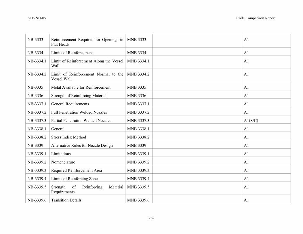
STP-NU-051 Code Comparison Report
262
NB-3333 Reinforcement Required for Openings in Flat Heads
MNB 3333 A1
NB-3334 Limits of Reinforcement MNB 3334 A1
NB-3334.1 Limit of Reinforcement Along the Vessel Wall
MNB 3334.1 A1
NB-3334.2 Limit of Reinforcement Normal to the Vessel Wall
MNB 3334.2 A1
NB-3335 Metal Available for Reinforcement MNB 3335 A1
NB-3336 Strength of Reinforcing Material MNB 3336 A1
NB-3337.1 General Requirements MNB 3337.1 A1
NB-3337.2 Full Penetration Welded Nozzles MNB 3337.2 A1
NB-3337.3 Partial Penetration Welded Nozzles MNB 3337.3 A1(S/C)
NB-3338.1 General MNB 3338.1 A1
NB-3338.2 Stress Index Method MNB 3338.2 A1
NB-3339 Alternative Rules for Nozzle Design MNB 3339 A1
NB-3339.1 Limitations MNB 3339.1 A1
NB-3339.2 Nomenclature MNB 3339.2 A1
NB-3339.3 Required Reinforcement Area MNB 3339.3 A1
NB-3339.4 Limits of Reinforcing Zone MNB 3339.4 A1
NB-3339.5 Strength of Reinforcing Material Requirements
MNB 3339.5 A1
NB-3339.6 Transition Details MNB 3339.6 A1
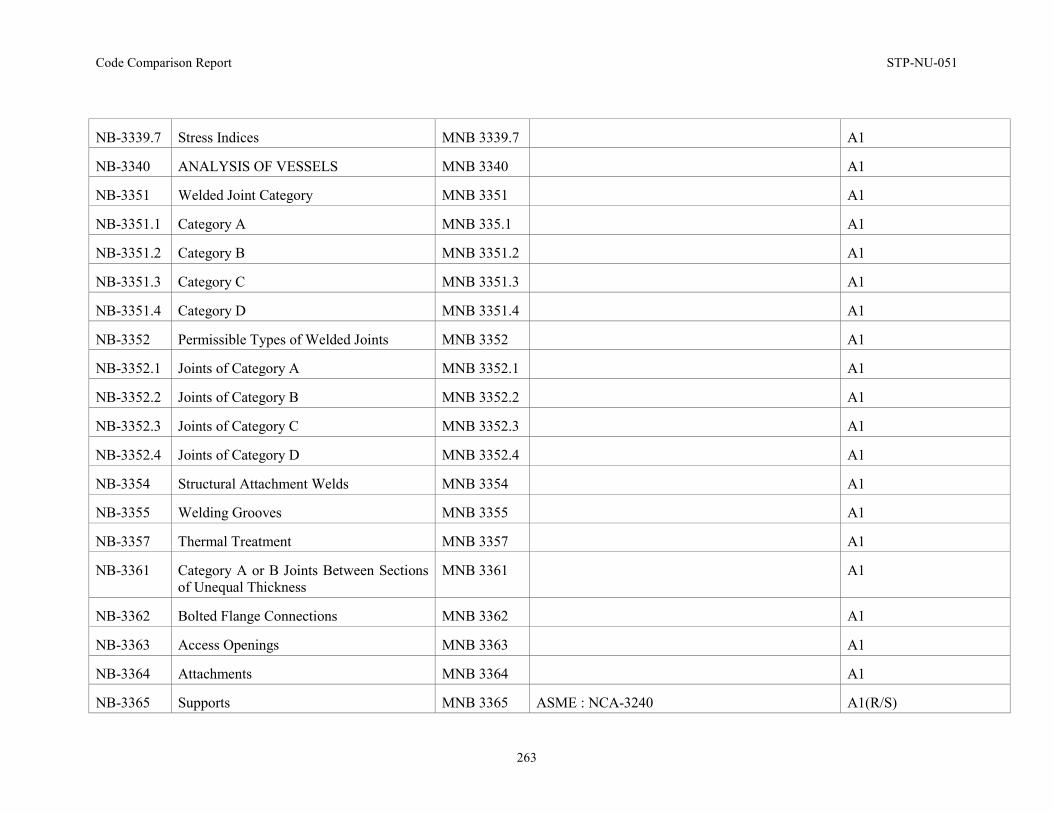
Code Comparison Report STP-NU-051
263
NB-3339.7 Stress Indices MNB 3339.7 A1
NB-3340 ANALYSIS OF VESSELS MNB 3340 A1
NB-3351 Welded Joint Category MNB 3351 A1
NB-3351.1 Category A MNB 335.1 A1
NB-3351.2 Category B MNB 3351.2 A1
NB-3351.3 Category C MNB 3351.3 A1
NB-3351.4 Category D MNB 3351.4 A1
NB-3352 Permissible Types of Welded Joints MNB 3352 A1
NB-3352.1 Joints of Category A MNB 3352.1 A1
NB-3352.2 Joints of Category B MNB 3352.2 A1
NB-3352.3 Joints of Category C MNB 3352.3 A1
NB-3352.4 Joints of Category D MNB 3352.4 A1
NB-3354 Structural Attachment Welds MNB 3354 A1
NB-3355 Welding Grooves MNB 3355 A1
NB-3357 Thermal Treatment MNB 3357 A1
NB-3361 Category A or B Joints Between Sections of Unequal Thickness
MNB 3361 A1
NB-3362 Bolted Flange Connections MNB 3362 A1
NB-3363 Access Openings MNB 3363 A1
NB-3364 Attachments MNB 3364 A1
NB-3365 Supports MNB 3365 ASME : NCA-3240 A1(R/S)
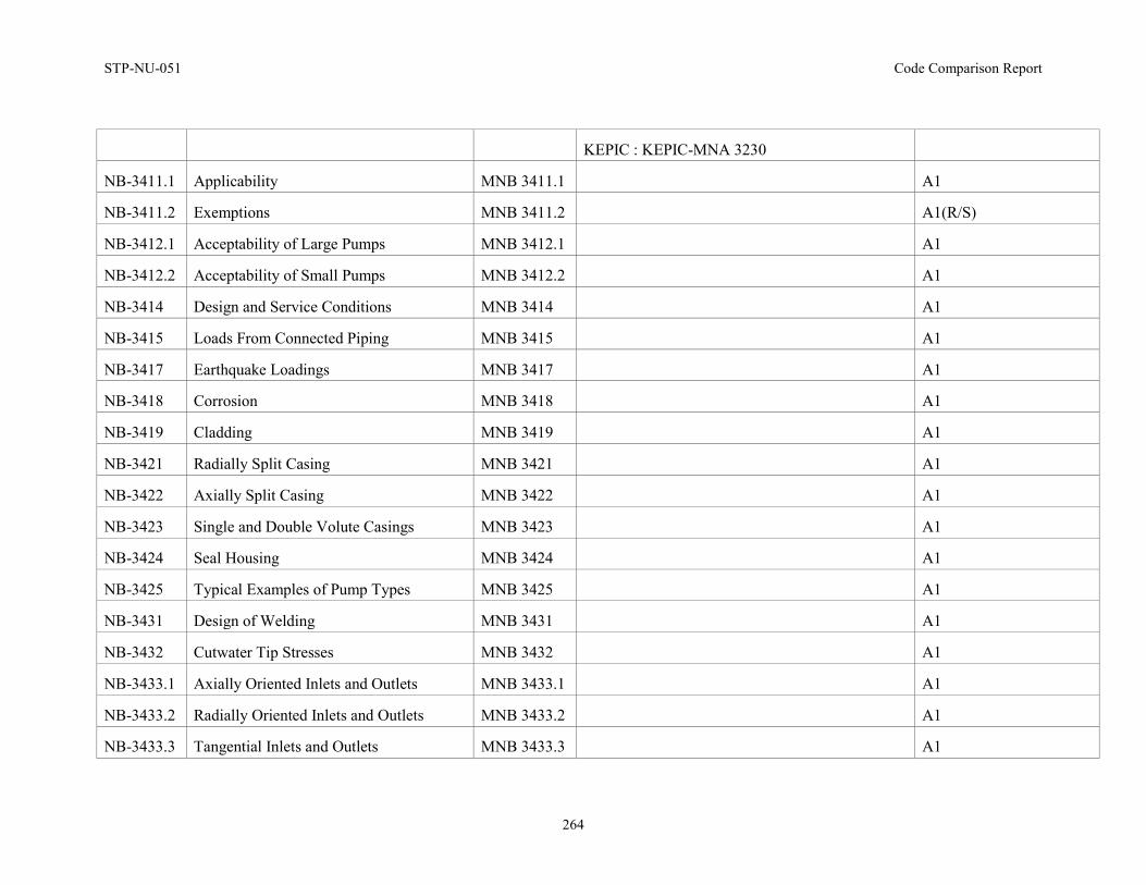
STP-NU-051 Code Comparison Report
264
KEPIC : KEPIC-MNA 3230
NB-3411.1 Applicability MNB 3411.1 A1
NB-3411.2 Exemptions MNB 3411.2 A1(R/S)
NB-3412.1 Acceptability of Large Pumps MNB 3412.1 A1
NB-3412.2 Acceptability of Small Pumps MNB 3412.2 A1
NB-3414 Design and Service Conditions MNB 3414 A1
NB-3415 Loads From Connected Piping MNB 3415 A1
NB-3417 Earthquake Loadings MNB 3417 A1
NB-3418 Corrosion MNB 3418 A1
NB-3419 Cladding MNB 3419 A1
NB-3421 Radially Split Casing MNB 3421 A1
NB-3422 Axially Split Casing MNB 3422 A1
NB-3423 Single and Double Volute Casings MNB 3423 A1
NB-3424 Seal Housing MNB 3424 A1
NB-3425 Typical Examples of Pump Types MNB 3425 A1
NB-3431 Design of Welding MNB 3431 A1
NB-3432 Cutwater Tip Stresses MNB 3432 A1
NB-3433.1 Axially Oriented Inlets and Outlets MNB 3433.1 A1
NB-3433.2 Radially Oriented Inlets and Outlets MNB 3433.2 A1
NB-3433.3 Tangential Inlets and Outlets MNB 3433.3 A1
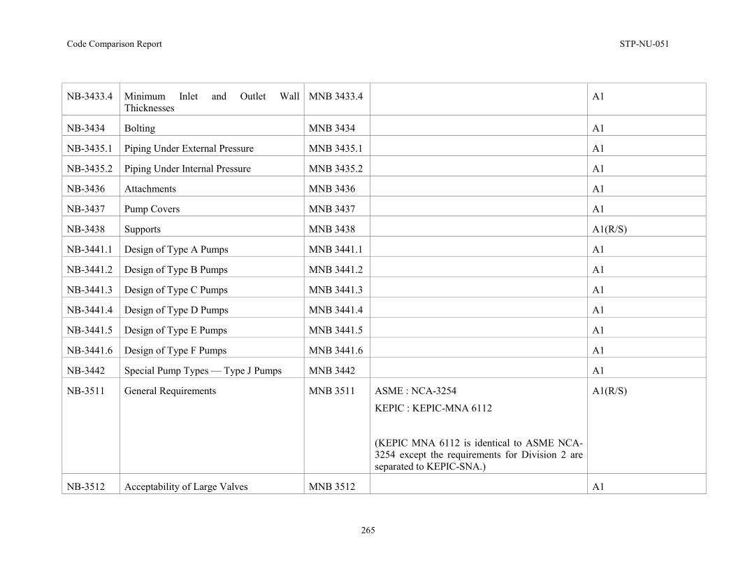
Code Comparison Report STP-NU-051
265
NB-3433.4 Minimum Inlet and Outlet Wall Thicknesses
MNB 3433.4 A1
NB-3434 Bolting MNB 3434 A1
NB-3435.1 Piping Under External Pressure MNB 3435.1 A1
NB-3435.2 Piping Under Internal Pressure MNB 3435.2 A1
NB-3436 Attachments MNB 3436 A1
NB-3437 Pump Covers MNB 3437 A1
NB-3438 Supports MNB 3438 A1(R/S)
NB-3441.1 Design of Type A Pumps MNB 3441.1 A1
NB-3441.2 Design of Type B Pumps MNB 3441.2 A1
NB-3441.3 Design of Type C Pumps MNB 3441.3 A1
NB-3441.4 Design of Type D Pumps MNB 3441.4 A1
NB-3441.5 Design of Type E Pumps MNB 3441.5 A1
NB-3441.6 Design of Type F Pumps MNB 3441.6 A1
NB-3442 Special Pump Types — Type J Pumps MNB 3442 A1
NB-3511 General Requirements MNB 3511 ASME : NCA-3254
KEPIC : KEPIC-MNA 6112
(KEPIC MNA 6112 is identical to ASME NCA-3254 except the requirements for Division 2 are separated to KEPIC-SNA.)
A1(R/S)
NB-3512 Acceptability of Large Valves MNB 3512 A1
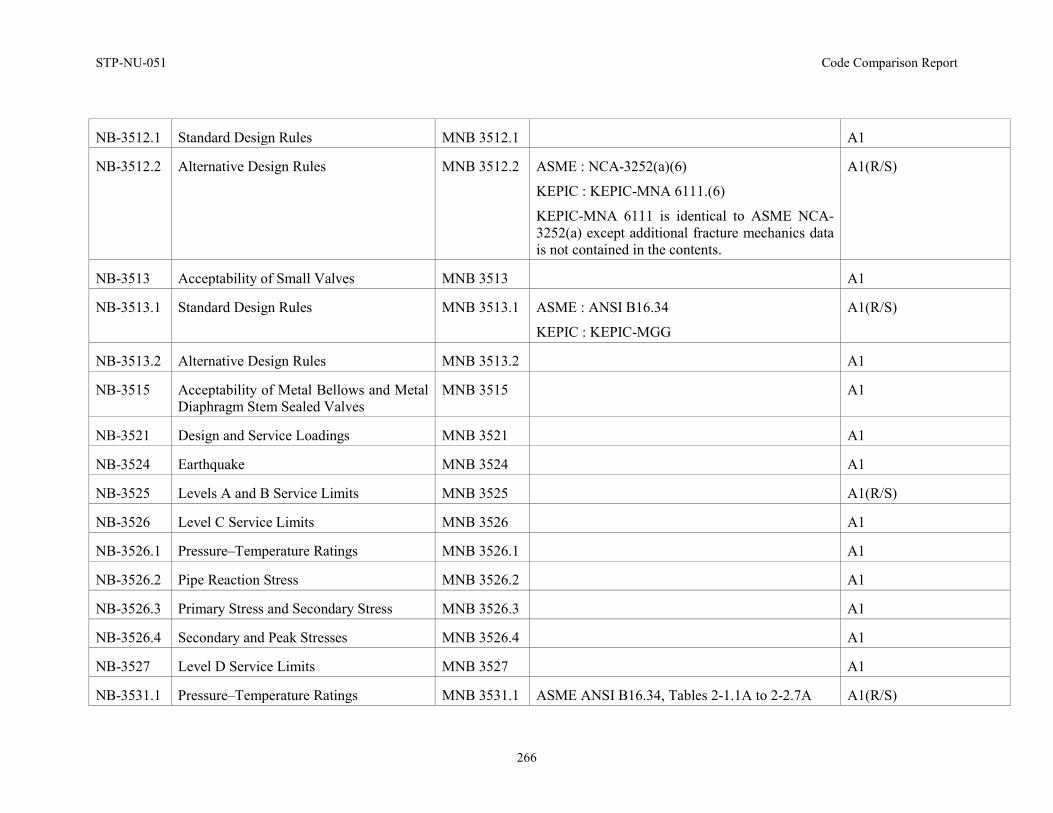
STP-NU-051 Code Comparison Report
266
NB-3512.1 Standard Design Rules MNB 3512.1 A1
NB-3512.2 Alternative Design Rules MNB 3512.2 ASME : NCA-3252(a)(6)
KEPIC : KEPIC-MNA 6111.(6)
KEPIC-MNA 6111 is identical to ASME NCA-3252(a) except additional fracture mechanics data is not contained in the contents.
A1(R/S)
NB-3513 Acceptability of Small Valves MNB 3513 A1
NB-3513.1 Standard Design Rules MNB 3513.1 ASME : ANSI B16.34
KEPIC : KEPIC-MGG
A1(R/S)
NB-3513.2 Alternative Design Rules MNB 3513.2 A1
NB-3515 Acceptability of Metal Bellows and Metal Diaphragm Stem Sealed Valves
MNB 3515 A1
NB-3521 Design and Service Loadings MNB 3521 A1
NB-3524 Earthquake MNB 3524 A1
NB-3525 Levels A and B Service Limits MNB 3525 A1(R/S)
NB-3526 Level C Service Limits MNB 3526 A1
NB-3526.1 Pressure–Temperature Ratings MNB 3526.1 A1
NB-3526.2 Pipe Reaction Stress MNB 3526.2 A1
NB-3526.3 Primary Stress and Secondary Stress MNB 3526.3 A1
NB-3526.4 Secondary and Peak Stresses MNB 3526.4 A1
NB-3527 Level D Service Limits MNB 3527 A1
NB-3531.1 Pressure–Temperature Ratings MNB 3531.1 ASME ANSI B16.34, Tables 2-1.1A to 2-2.7A A1(R/S)
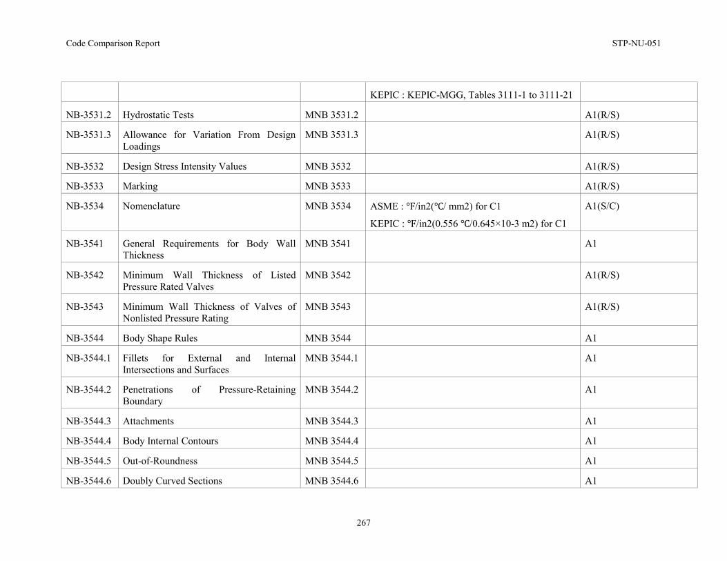
Code Comparison Report STP-NU-051
267
KEPIC : KEPIC-MGG, Tables 3111-1 to 3111-21
NB-3531.2 Hydrostatic Tests MNB 3531.2 A1(R/S)
NB-3531.3 Allowance for Variation From Design Loadings
MNB 3531.3 A1(R/S)
NB-3532 Design Stress Intensity Values MNB 3532 A1(R/S)
NB-3533 Marking MNB 3533 A1(R/S)
NB-3534 Nomenclature MNB 3534 ASME : ℉/in2(℃/ mm2) for C1
KEPIC : ℉/in2(0.556 ℃/0.645×10-3 m2) for C1
A1(S/C)
NB-3541 General Requirements for Body Wall Thickness
MNB 3541 A1
NB-3542 Minimum Wall Thickness of Listed Pressure Rated Valves
MNB 3542 A1(R/S)
NB-3543 Minimum Wall Thickness of Valves of Nonlisted Pressure Rating
MNB 3543 A1(R/S)
NB-3544 Body Shape Rules MNB 3544 A1
NB-3544.1 Fillets for External and Internal Intersections and Surfaces
MNB 3544.1 A1
NB-3544.2 Penetrations of Pressure-Retaining Boundary
MNB 3544.2 A1
NB-3544.3 Attachments MNB 3544.3 A1
NB-3544.4 Body Internal Contours MNB 3544.4 A1
NB-3544.5 Out-of-Roundness MNB 3544.5 A1
NB-3544.6 Doubly Curved Sections MNB 3544.6 A1
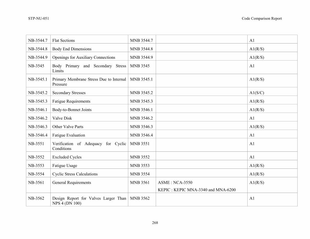
STP-NU-051 Code Comparison Report
268
NB-3544.7 Flat Sections MNB 3544.7 A1
NB-3544.8 Body End Dimensions MNB 3544.8 A1(R/S)
NB-3544.9 Openings for Auxiliary Connections MNB 3544.9 A1(R/S)
NB-3545 Body Primary and Secondary Stress Limits
MNB 3545 A1
NB-3545.1 Primary Membrane Stress Due to Internal Pressure
MNB 3545.1 A1(R/S)
NB-3545.2 Secondary Stresses MNB 3545.2 A1(S/C)
NB-3545.3 Fatigue Requirements MNB 3545.3 A1(R/S)
NB-3546.1 Body-to-Bonnet Joints MNB 3546.1 A1(R/S)
NB-3546.2 Valve Disk MNB 3546.2 A1
NB-3546.3 Other Valve Parts MNB 3546.3 A1(R/S)
NB-3546.4 Fatigue Evaluation MNB 3546.4 A1
NB-3551 Verification of Adequacy for Cyclic Conditions
MNB 3551 A1
NB-3552 Excluded Cycles MNB 3552 A1
NB-3553 Fatigue Usage MNB 3553 A1(R/S)
NB-3554 Cyclic Stress Calculations MNB 3554 A1(R/S)
NB-3561 General Requirements MNB 3561 ASME : NCA-3550
KEPIC : KEPIC MNA-3340 and MNA-6200
A1(R/S)
NB-3562 Design Report for Valves Larger Than NPS 4 (DN 100)
MNB 3562 A1
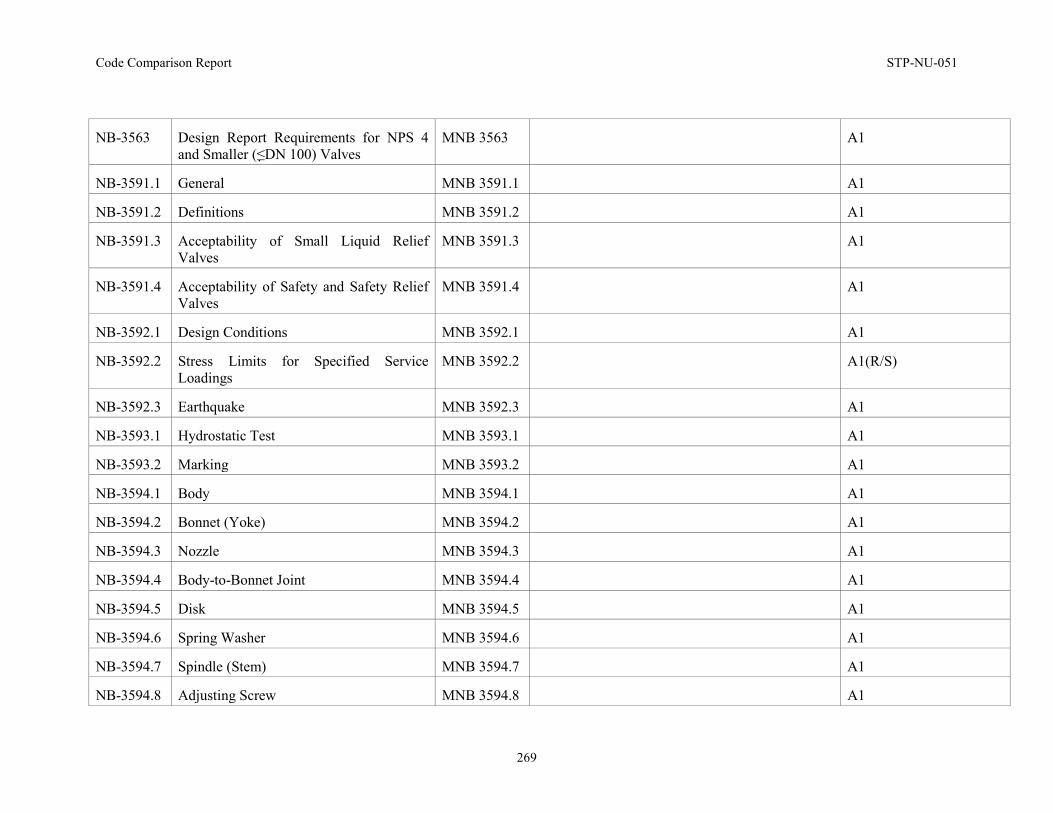
Code Comparison Report STP-NU-051
269
NB-3563 Design Report Requirements for NPS 4 and Smaller (≤DN 100) Valves
MNB 3563 A1
NB-3591.1 General MNB 3591.1 A1
NB-3591.2 Definitions MNB 3591.2 A1
NB-3591.3 Acceptability of Small Liquid Relief Valves
MNB 3591.3 A1
NB-3591.4 Acceptability of Safety and Safety Relief Valves
MNB 3591.4 A1
NB-3592.1 Design Conditions MNB 3592.1 A1
NB-3592.2 Stress Limits for Specified Service Loadings
MNB 3592.2 A1(R/S)
NB-3592.3 Earthquake MNB 3592.3 A1
NB-3593.1 Hydrostatic Test MNB 3593.1 A1
NB-3593.2 Marking MNB 3593.2 A1
NB-3594.1 Body MNB 3594.1 A1
NB-3594.2 Bonnet (Yoke) MNB 3594.2 A1
NB-3594.3 Nozzle MNB 3594.3 A1
NB-3594.4 Body-to-Bonnet Joint MNB 3594.4 A1
NB-3594.5 Disk MNB 3594.5 A1
NB-3594.6 Spring Washer MNB 3594.6 A1
NB-3594.7 Spindle (Stem) MNB 3594.7 A1
NB-3594.8 Adjusting Screw MNB 3594.8 A1
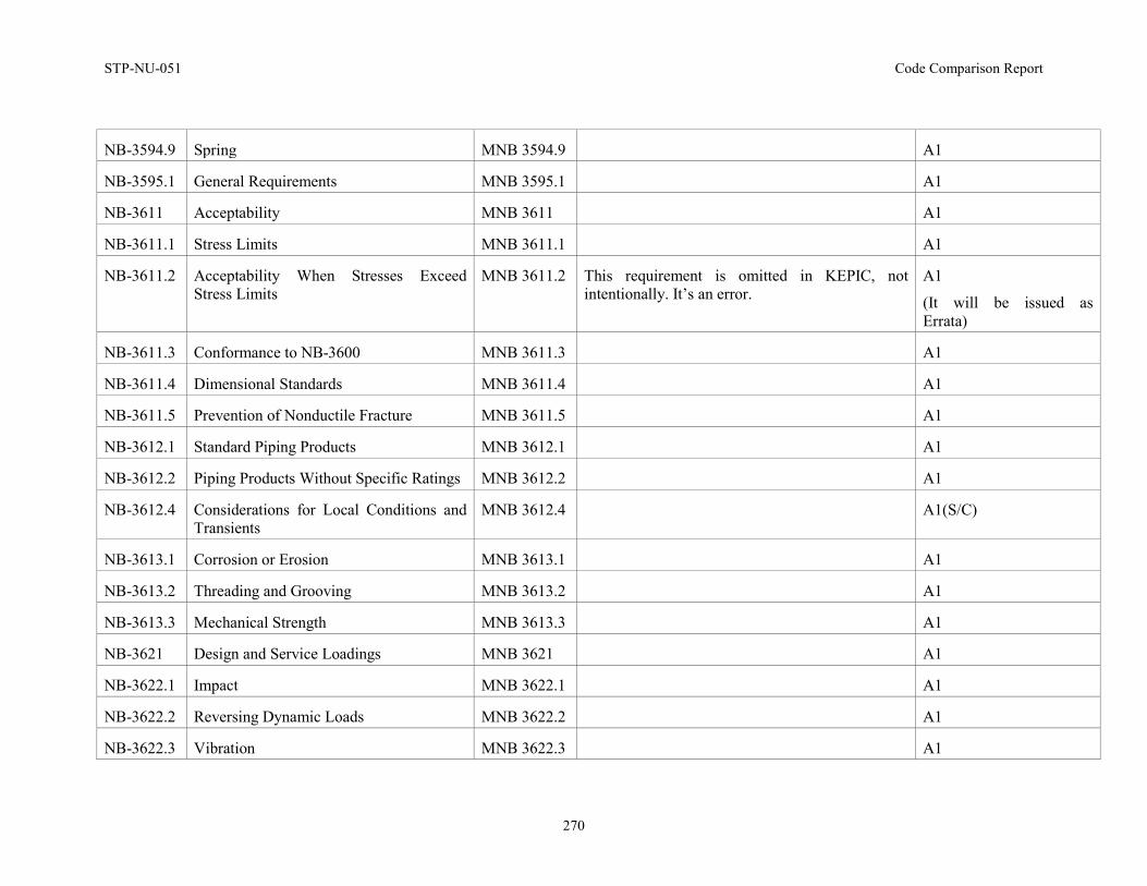
STP-NU-051 Code Comparison Report
270
NB-3594.9 Spring MNB 3594.9 A1
NB-3595.1 General Requirements MNB 3595.1 A1
NB-3611 Acceptability MNB 3611 A1
NB-3611.1 Stress Limits MNB 3611.1 A1
NB-3611.2 Acceptability When Stresses Exceed Stress Limits
MNB 3611.2 This requirement is omitted in KEPIC, not intentionally. It’s an error.
A1
(It will be issued as Errata)
NB-3611.3 Conformance to NB-3600 MNB 3611.3 A1
NB-3611.4 Dimensional Standards MNB 3611.4 A1
NB-3611.5 Prevention of Nonductile Fracture MNB 3611.5 A1
NB-3612.1 Standard Piping Products MNB 3612.1 A1
NB-3612.2 Piping Products Without Specific Ratings MNB 3612.2 A1
NB-3612.4 Considerations for Local Conditions and Transients
MNB 3612.4 A1(S/C)
NB-3613.1 Corrosion or Erosion MNB 3613.1 A1
NB-3613.2 Threading and Grooving MNB 3613.2 A1
NB-3613.3 Mechanical Strength MNB 3613.3 A1
NB-3621 Design and Service Loadings MNB 3621 A1
NB-3622.1 Impact MNB 3622.1 A1
NB-3622.2 Reversing Dynamic Loads MNB 3622.2 A1
NB-3622.3 Vibration MNB 3622.3 A1
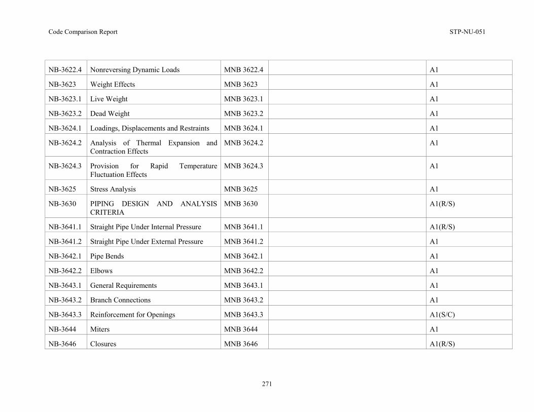
Code Comparison Report STP-NU-051
271
NB-3622.4 Nonreversing Dynamic Loads MNB 3622.4 A1
NB-3623 Weight Effects MNB 3623 A1
NB-3623.1 Live Weight MNB 3623.1 A1
NB-3623.2 Dead Weight MNB 3623.2 A1
NB-3624.1 Loadings, Displacements and Restraints MNB 3624.1 A1
NB-3624.2 Analysis of Thermal Expansion and Contraction Effects
MNB 3624.2 A1
NB-3624.3 Provision for Rapid Temperature Fluctuation Effects
MNB 3624.3 A1
NB-3625 Stress Analysis MNB 3625 A1
NB-3630 PIPING DESIGN AND ANALYSIS CRITERIA
MNB 3630 A1(R/S)
NB-3641.1 Straight Pipe Under Internal Pressure MNB 3641.1 A1(R/S)
NB-3641.2 Straight Pipe Under External Pressure MNB 3641.2 A1
NB-3642.1 Pipe Bends MNB 3642.1 A1
NB-3642.2 Elbows MNB 3642.2 A1
NB-3643.1 General Requirements MNB 3643.1 A1
NB-3643.2 Branch Connections MNB 3643.2 A1
NB-3643.3 Reinforcement for Openings MNB 3643.3 A1(S/C)
NB-3644 Miters MNB 3644 A1
NB-3646 Closures MNB 3646 A1(R/S)
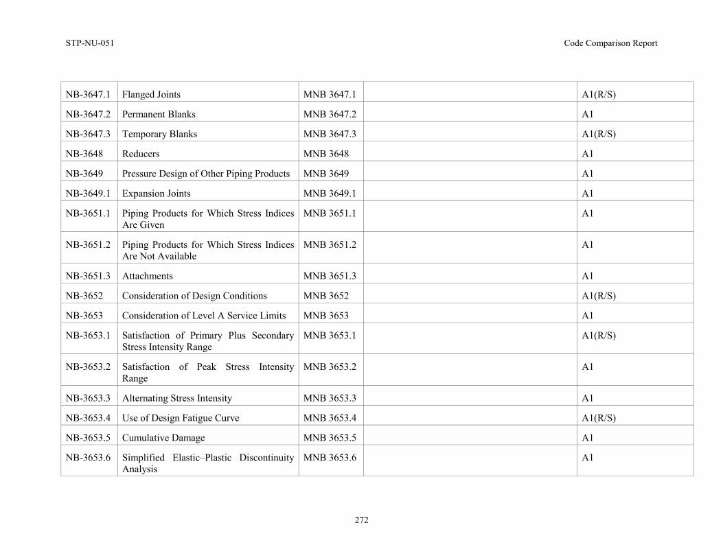
STP-NU-051 Code Comparison Report
272
NB-3647.1 Flanged Joints MNB 3647.1 A1(R/S)
NB-3647.2 Permanent Blanks MNB 3647.2 A1
NB-3647.3 Temporary Blanks MNB 3647.3 A1(R/S)
NB-3648 Reducers MNB 3648 A1
NB-3649 Pressure Design of Other Piping Products MNB 3649 A1
NB-3649.1 Expansion Joints MNB 3649.1 A1
NB-3651.1 Piping Products for Which Stress Indices Are Given
MNB 3651.1 A1
NB-3651.2 Piping Products for Which Stress Indices Are Not Available
MNB 3651.2 A1
NB-3651.3 Attachments MNB 3651.3 A1
NB-3652 Consideration of Design Conditions MNB 3652 A1(R/S)
NB-3653 Consideration of Level A Service Limits MNB 3653 A1
NB-3653.1 Satisfaction of Primary Plus Secondary Stress Intensity Range
MNB 3653.1 A1(R/S)
NB-3653.2 Satisfaction of Peak Stress Intensity Range
MNB 3653.2 A1
NB-3653.3 Alternating Stress Intensity MNB 3653.3 A1
NB-3653.4 Use of Design Fatigue Curve MNB 3653.4 A1(R/S)
NB-3653.5 Cumulative Damage MNB 3653.5 A1
NB-3653.6 Simplified Elastic–Plastic Discontinuity Analysis
MNB 3653.6 A1
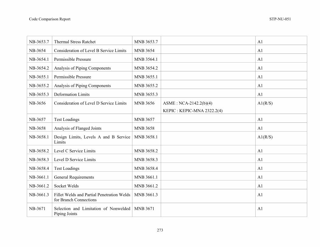
Code Comparison Report STP-NU-051
273
NB-3653.7 Thermal Stress Ratchet MNB 3653.7 A1
NB-3654 Consideration of Level B Service Limits MNB 3654 A1
NB-3654.1 Permissible Pressure MNB 3564.1 A1
NB-3654.2 Analysis of Piping Components MNB 3654.2 A1
NB-3655.1 Permissible Pressure MNB 3655.1 A1
NB-3655.2 Analysis of Piping Components MNB 3655.2 A1
NB-3655.3 Deformation Limits MNB 3655.3 A1
NB-3656 Consideration of Level D Service Limits MNB 3656 ASME : NCA-2142.2(b)(4)
KEPIC : KEPIC-MNA 2322.2(4)
A1(R/S)
NB-3657 Test Loadings MNB 3657 A1
NB-3658 Analysis of Flanged Joints MNB 3658 A1
NB-3658.1 Design Limits, Levels A and B Service Limits
MNB 3658.1 A1(R/S)
NB-3658.2 Level C Service Limits MNB 3658.2 A1
NB-3658.3 Level D Service Limits MNB 3658.3 A1
NB-3658.4 Test Loadings MNB 3658.4 A1
NB-3661.1 General Requirements MNB 3661.1 A1
NB-3661.2 Socket Welds MNB 3661.2 A1
NB-3661.3 Fillet Welds and Partial Penetration Welds for Branch Connections
MNB 3661.3 A1
NB-3671 Selection and Limitation of Nonwelded Piping Joints
MNB 3671 A1
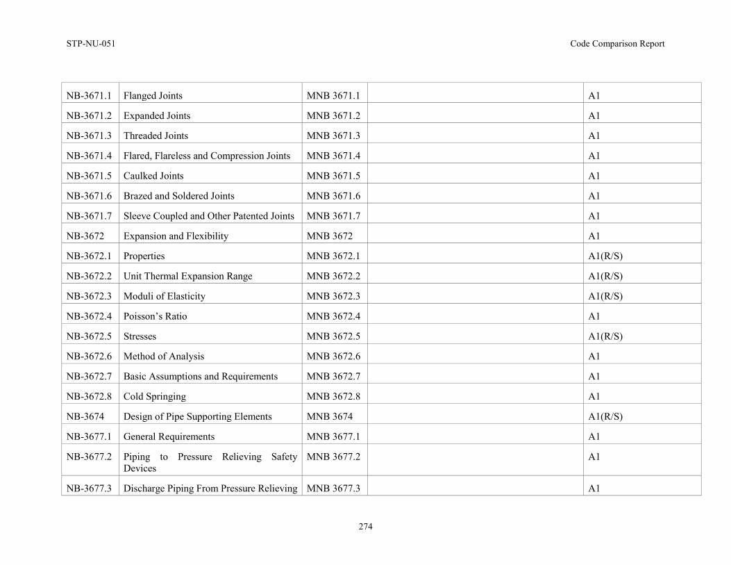
STP-NU-051 Code Comparison Report
274
NB-3671.1 Flanged Joints MNB 3671.1 A1
NB-3671.2 Expanded Joints MNB 3671.2 A1
NB-3671.3 Threaded Joints MNB 3671.3 A1
NB-3671.4 Flared, Flareless and Compression Joints MNB 3671.4 A1
NB-3671.5 Caulked Joints MNB 3671.5 A1
NB-3671.6 Brazed and Soldered Joints MNB 3671.6 A1
NB-3671.7 Sleeve Coupled and Other Patented Joints MNB 3671.7 A1
NB-3672 Expansion and Flexibility MNB 3672 A1
NB-3672.1 Properties MNB 3672.1 A1(R/S)
NB-3672.2 Unit Thermal Expansion Range MNB 3672.2 A1(R/S)
NB-3672.3 Moduli of Elasticity MNB 3672.3 A1(R/S)
NB-3672.4 Poisson’s Ratio MNB 3672.4 A1
NB-3672.5 Stresses MNB 3672.5 A1(R/S)
NB-3672.6 Method of Analysis MNB 3672.6 A1
NB-3672.7 Basic Assumptions and Requirements MNB 3672.7 A1
NB-3672.8 Cold Springing MNB 3672.8 A1
NB-3674 Design of Pipe Supporting Elements MNB 3674 A1(R/S)
NB-3677.1 General Requirements MNB 3677.1 A1
NB-3677.2 Piping to Pressure Relieving Safety Devices
MNB 3677.2 A1
NB-3677.3 Discharge Piping From Pressure Relieving MNB 3677.3 A1
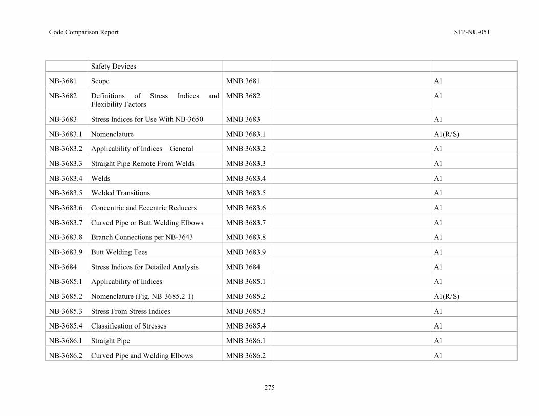
Code Comparison Report STP-NU-051
275
Safety Devices
NB-3681 Scope MNB 3681 A1
NB-3682 Definitions of Stress Indices and Flexibility Factors
MNB 3682 A1
NB-3683 Stress Indices for Use With NB-3650 MNB 3683 A1
NB-3683.1 Nomenclature MNB 3683.1 A1(R/S)
NB-3683.2 Applicability of Indices—General MNB 3683.2 A1
NB-3683.3 Straight Pipe Remote From Welds MNB 3683.3 A1
NB-3683.4 Welds MNB 3683.4 A1
NB-3683.5 Welded Transitions MNB 3683.5 A1
NB-3683.6 Concentric and Eccentric Reducers MNB 3683.6 A1
NB-3683.7 Curved Pipe or Butt Welding Elbows MNB 3683.7 A1
NB-3683.8 Branch Connections per NB-3643 MNB 3683.8 A1
NB-3683.9 Butt Welding Tees MNB 3683.9 A1
NB-3684 Stress Indices for Detailed Analysis MNB 3684 A1
NB-3685.1 Applicability of Indices MNB 3685.1 A1
NB-3685.2 Nomenclature (Fig. NB-3685.2-1) MNB 3685.2 A1(R/S)
NB-3685.3 Stress From Stress Indices MNB 3685.3 A1
NB-3685.4 Classification of Stresses MNB 3685.4 A1
NB-3686.1 Straight Pipe MNB 3686.1 A1
NB-3686.2 Curved Pipe and Welding Elbows MNB 3686.2 A1
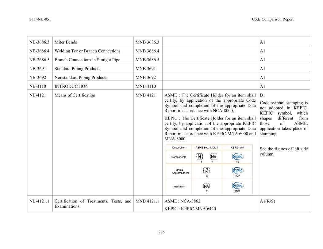
STP-NU-051 Code Comparison Report
276
NB-3686.3 Miter Bends MNB 3686.3 A1
NB-3686.4 Welding Tee or Branch Connections MNB 3686.4 A1
NB-3686.5 Branch Connections in Straight Pipe MNB 3686.5 A1
NB-3691 Standard Piping Products MNB 3691 A1
NB-3692 Nonstandard Piping Products MNB 3692 A1
NB-4110 INTRODUCTION MNB 4110 A1
NB-4121 Means of Certification MNB 4121 ASME : The Certificate Holder for an item shall certify, by application of the appropriate Code Symbol and completion of the appropriate Data Report in accordance with NCA-8000,
KEPIC : The Certificate Holder for an item shall certify, by application of the appropriate KEPIC Symbol and completion of the appropriate Data Report in accordance with KEPIC-MNA 6000 and MNA-8000.
B1
Code symbol stamping is not adopted in KEPIC. KEPIC symbol, which shapes different from those of ASME, application takes place of stamping.
See the figures of left side column.
NB-4121.1 Certification of Treatments, Tests, and Examinations
MNB 4121.1 ASME : NCA-3862
KEPIC : KEPIC-MNA 6420
A1(R/S)
Code Comparison Report STP-NU-051
277
NB-4121.2 Repetition of Tensile or Impact Tests MNB 4121.2 A1
NB-4121.3 Repetition of Surface Examination After Machining
MNB 4121.2 A1
NB-4122 Material Identification MNB 4122 A1
NB-4122.1 Marking Material MNB 4122.1 A1
NB-4123 Examinations MNB 4123 A1
NB-4125 Testing of Welding and Brazing Material MNB 4125 A1
NB-4131 Elimination and Repair of Defects MNB 4131 A1
NB-4132 Documentation of Repair Welds of Base Material
MNB 4132 A1
NB-4211 Cutting MNB 4211 A1
NB-4211.1 Preheating Before Thermal Cutting MNB 4211.1 A1
NB-4212 Forming and Bending Processes MNB 4212 A1
NB-4213 Qualification of Forming Processes for Impact Property Requirements
MNB 4213 A1
NB-4213.1 Exemptions MNB 4213.1 A1
NB-4213.2 Procedure Qualification Test MNB 4213.2 A1
NB-4213.3 Acceptance Criteria for Formed Material MNB 4213.3 A1
NB-4213.4 Requalification MNB 4213.4 A1(C/S)
NB-4214 Minimum Thickness of Fabricated Material
MNB 4214 A1
NB-4221 Tolerance for Vessel Shells MNB 4221 A1
STP-NU-051 Code Comparison Report
278
NB-4221.1 Maximum Difference in Cross-Sectional Diameters
MNB 4221.1 A1
NB-4221.2 Maximum Deviation From True Theoretical Form for External Pressure
MNB 4221.2 A1
NB-4221.3 Deviations From Tolerances MNB 4221.3 ASME : NCA-3551
KEPIC : KEPIC-MNA 6200
A1(R/S)
NB-4221.4 Tolerance Deviations for Vessel Parts Fabricated From Pipe
MNB 4221.4 A1
NB-4222 Tolerances for Formed Vessel Heads MNB 4222 A1
NB-4222.1 Maximum Difference in Cross-Sectional Diameters
MNB 4222.1 A1
NB-4222.2 Deviation From Specified Shape MNB 4222.2 A1
NB-4223 Tolerances for Formed or Bent Piping MNB 4223 A1
NB-4223.1 Minimum Wall Thickness MNB 4223.1 A1
NB-4223.2 Ovality Tolerance MNB 4223.2 A1
NB-4231 Fitting and Aligning Methods MNB 4231 A1
NB-4231.1 Tack Welds MNB 4231.1 A1
NB-4232 Alignment Requirements When Components Are Welded From Two Sides
MNB 4232 A1
NB-4232.1 Fairing of Offsets MNB 4232.1 A1
NB-4233 Alignment Requirements When Inside Surfaces Are Inaccessible
MNB 4233 A1(C/S)
NB-4241 Category A Weld Joints in Vessels and MNB 4241 A1
Code Comparison Report STP-NU-051
279
Longitudinal Weld Joints in Other Components
NB-4242 Category B Weld Joints in Vessels and Circumferential Weld Joints in Other Components
MNB 4242 A1
NB-4243 Category C Weld Joints in Vessels and Similar Weld Joints in Other Components
MNB 4243 A1
NB-4244 Category D Weld Joints in Vessels and Similar Weld Joints in Other Components
MNB 4244 A1
NB-4245 Complete Joint Penetration Welds MNB 4245 A1
NB-4246 Piping Branch Connections MNB 4246 A1
NB-4250 WELDING END TRANSITIONS —MAXIMUM ENVELOPE
MNB 4250 ASME : (c) if the weld is subject to preservice inspection, the length of the counterbore shall be 2tmin for pipe and t min for components and fittings,
KEPIC : KEPIC-MNB has the same requirement for the above.
(But, KEPIC allows 0.5 in. length of countbore for fittings such as elbows through KEPIC Code Case in the year 2009 based on the construction experience of NPPs. However, It needs permission for usage by regulation body.)
A1
(Discussion is required for KEPIC Code Case. I wonder whether Code Case is one of object of code comparison work or not)
NB-4311 Types of Processes Permitted MNB 4311 A1(R/S)
NB-4311.1 Stud Welding Restrictions MNB 4311.1 A1(R/S)
NB-4311.2 Capacitor Discharge Welding MNB 4311.2 A1(C/S)
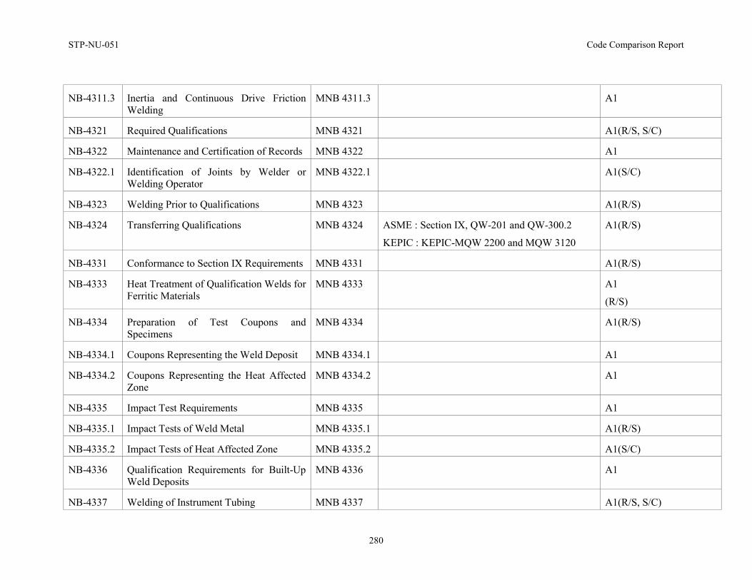
STP-NU-051 Code Comparison Report
280
NB-4311.3 Inertia and Continuous Drive Friction Welding
MNB 4311.3 A1
NB-4321 Required Qualifications MNB 4321 A1(R/S, S/C)
NB-4322 Maintenance and Certification of Records MNB 4322 A1
NB-4322.1 Identification of Joints by Welder or Welding Operator
MNB 4322.1 A1(S/C)
NB-4323 Welding Prior to Qualifications MNB 4323 A1(R/S)
NB-4324 Transferring Qualifications MNB 4324 ASME : Section IX, QW-201 and QW-300.2
KEPIC : KEPIC-MQW 2200 and MQW 3120
A1(R/S)
NB-4331 Conformance to Section IX Requirements MNB 4331 A1(R/S)
NB-4333 Heat Treatment of Qualification Welds for Ferritic Materials
MNB 4333 A1
(R/S)
NB-4334 Preparation of Test Coupons and Specimens
MNB 4334 A1(R/S)
NB-4334.1 Coupons Representing the Weld Deposit MNB 4334.1 A1
NB-4334.2 Coupons Representing the Heat Affected Zone
MNB 4334.2 A1
NB-4335 Impact Test Requirements MNB 4335 A1
NB-4335.1 Impact Tests of Weld Metal MNB 4335.1 A1(R/S)
NB-4335.2 Impact Tests of Heat Affected Zone MNB 4335.2 A1(S/C)
NB-4336 Qualification Requirements for Built-Up Weld Deposits
MNB 4336 A1
NB-4337 Welding of Instrument Tubing MNB 4337 A1(R/S, S/C)
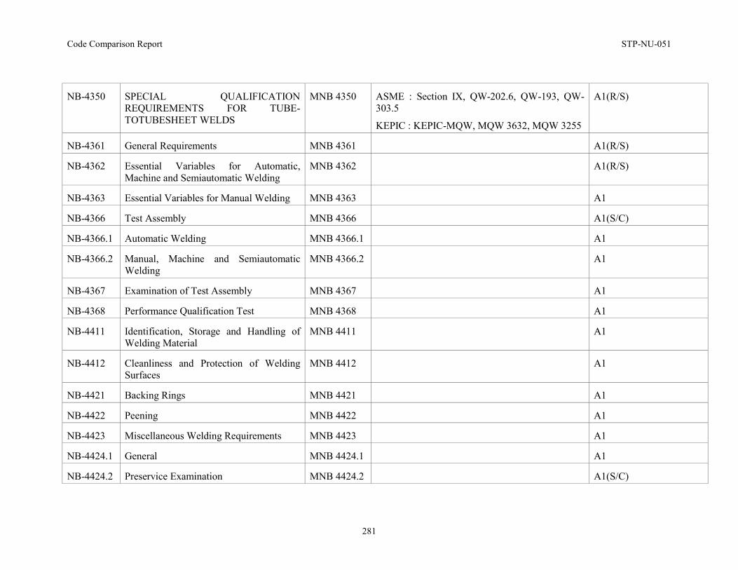
Code Comparison Report STP-NU-051
281
NB-4350 SPECIAL QUALIFICATION REQUIREMENTS FOR TUBE-TOTUBESHEET WELDS
MNB 4350 ASME : Section IX, QW-202.6, QW-193, QW-303.5
KEPIC : KEPIC-MQW, MQW 3632, MQW 3255
A1(R/S)
NB-4361 General Requirements MNB 4361 A1(R/S)
NB-4362 Essential Variables for Automatic, Machine and Semiautomatic Welding
MNB 4362 A1(R/S)
NB-4363 Essential Variables for Manual Welding MNB 4363 A1
NB-4366 Test Assembly MNB 4366 A1(S/C)
NB-4366.1 Automatic Welding MNB 4366.1 A1
NB-4366.2 Manual, Machine and Semiautomatic Welding
MNB 4366.2 A1
NB-4367 Examination of Test Assembly MNB 4367 A1
NB-4368 Performance Qualification Test MNB 4368 A1
NB-4411 Identification, Storage and Handling of Welding Material
MNB 4411 A1
NB-4412 Cleanliness and Protection of Welding Surfaces
MNB 4412 A1
NB-4421 Backing Rings MNB 4421 A1
NB-4422 Peening MNB 4422 A1
NB-4423 Miscellaneous Welding Requirements MNB 4423 A1
NB-4424.1 General MNB 4424.1 A1
NB-4424.2 Preservice Examination MNB 4424.2 A1(S/C)
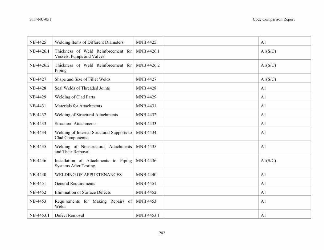
STP-NU-051 Code Comparison Report
282
NB-4425 Welding Items of Different Diameters MNB 4425 A1
NB-4426.1 Thickness of Weld Reinforcement for Vessels, Pumps and Valves
MNB 4426.1 A1(S/C)
NB-4426.2 Thickness of Weld Reinforcement for Piping
MNB 4426.2 A1(S/C)
NB-4427 Shape and Size of Fillet Welds MNB 4427 A1(S/C)
NB-4428 Seal Welds of Threaded Joints MNB 4428 A1
NB-4429 Welding of Clad Parts MNB 4429 A1
NB-4431 Materials for Attachments MNB 4431 A1
NB-4432 Welding of Structural Attachments MNB 4432 A1
NB-4433 Structural Attachments MNB 4433 A1
NB-4434 Welding of Internal Structural Supports to Clad Components
MNB 4434 A1
NB-4435 Welding of Nonstructural Attachments and Their Removal
MNB 4435 A1
NB-4436 Installation of Attachments to Piping Systems After Testing
MNB 4436 A1(S/C)
NB-4440 WELDING OF APPURTENANCES MNB 4440 A1
NB-4451 General Requirements MNB 4451 A1
NB-4452 Elimination of Surface Defects MNB 4452 A1
NB-4453 Requirements for Making Repairs of Welds
MNB 4453 A1
NB-4453.1 Defect Removal MNB 4453.1 A1
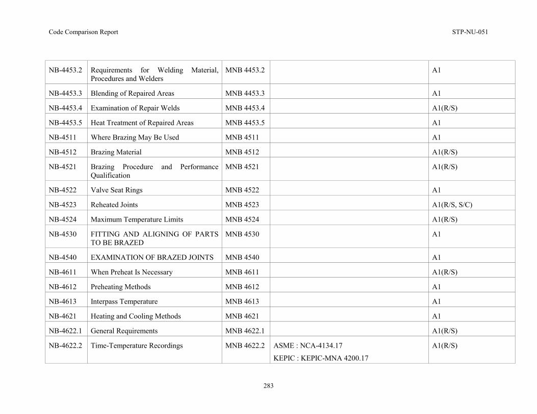
Code Comparison Report STP-NU-051
283
NB-4453.2 Requirements for Welding Material, Procedures and Welders
MNB 4453.2 A1
NB-4453.3 Blending of Repaired Areas MNB 4453.3 A1
NB-4453.4 Examination of Repair Welds MNB 4453.4 A1(R/S)
NB-4453.5 Heat Treatment of Repaired Areas MNB 4453.5 A1
NB-4511 Where Brazing May Be Used MNB 4511 A1
NB-4512 Brazing Material MNB 4512 A1(R/S)
NB-4521 Brazing Procedure and Performance Qualification
MNB 4521 A1(R/S)
NB-4522 Valve Seat Rings MNB 4522 A1
NB-4523 Reheated Joints MNB 4523 A1(R/S, S/C)
NB-4524 Maximum Temperature Limits MNB 4524 A1(R/S)
NB-4530 FITTING AND ALIGNING OF PARTS TO BE BRAZED
MNB 4530 A1
NB-4540 EXAMINATION OF BRAZED JOINTS MNB 4540 A1
NB-4611 When Preheat Is Necessary MNB 4611 A1(R/S)
NB-4612 Preheating Methods MNB 4612 A1
NB-4613 Interpass Temperature MNB 4613 A1
NB-4621 Heating and Cooling Methods MNB 4621 A1
NB-4622.1 General Requirements MNB 4622.1 A1(R/S)
NB-4622.2 Time-Temperature Recordings MNB 4622.2 ASME : NCA-4134.17
KEPIC : KEPIC-MNA 4200.17
A1(R/S)
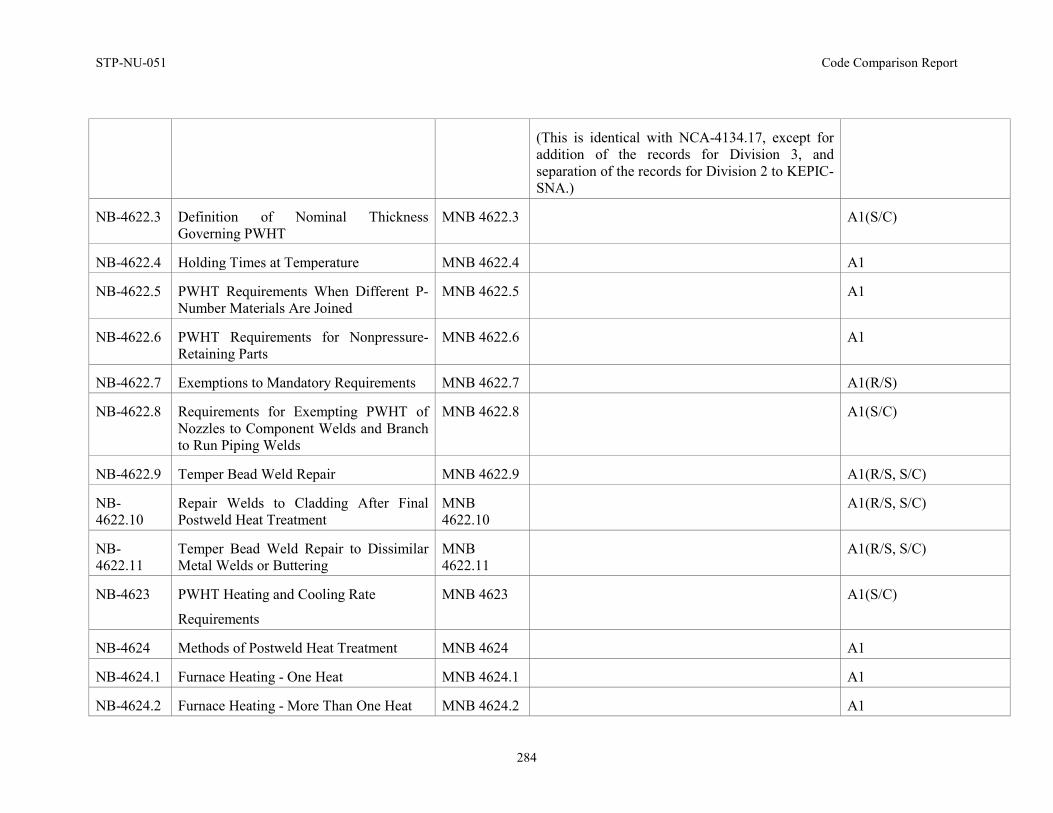
STP-NU-051 Code Comparison Report
284
(This is identical with NCA-4134.17, except for addition of the records for Division 3, and separation of the records for Division 2 to KEPIC-SNA.)
NB-4622.3 Definition of Nominal Thickness Governing PWHT
MNB 4622.3 A1(S/C)
NB-4622.4 Holding Times at Temperature MNB 4622.4 A1
NB-4622.5 PWHT Requirements When Different P-Number Materials Are Joined
MNB 4622.5 A1
NB-4622.6 PWHT Requirements for Nonpressure-Retaining Parts
MNB 4622.6 A1
NB-4622.7 Exemptions to Mandatory Requirements MNB 4622.7 A1(R/S)
NB-4622.8 Requirements for Exempting PWHT of Nozzles to Component Welds and Branch to Run Piping Welds
MNB 4622.8 A1(S/C)
NB-4622.9 Temper Bead Weld Repair MNB 4622.9 A1(R/S, S/C)
NB-4622.10
Repair Welds to Cladding After Final Postweld Heat Treatment
MNB 4622.10
A1(R/S, S/C)
NB-4622.11
Temper Bead Weld Repair to Dissimilar Metal Welds or Buttering
MNB 4622.11
A1(R/S, S/C)
NB-4623 PWHT Heating and Cooling Rate
Requirements
MNB 4623 A1(S/C)
NB-4624 Methods of Postweld Heat Treatment MNB 4624 A1
NB-4624.1 Furnace Heating - One Heat MNB 4624.1 A1
NB-4624.2 Furnace Heating - More Than One Heat MNB 4624.2 A1
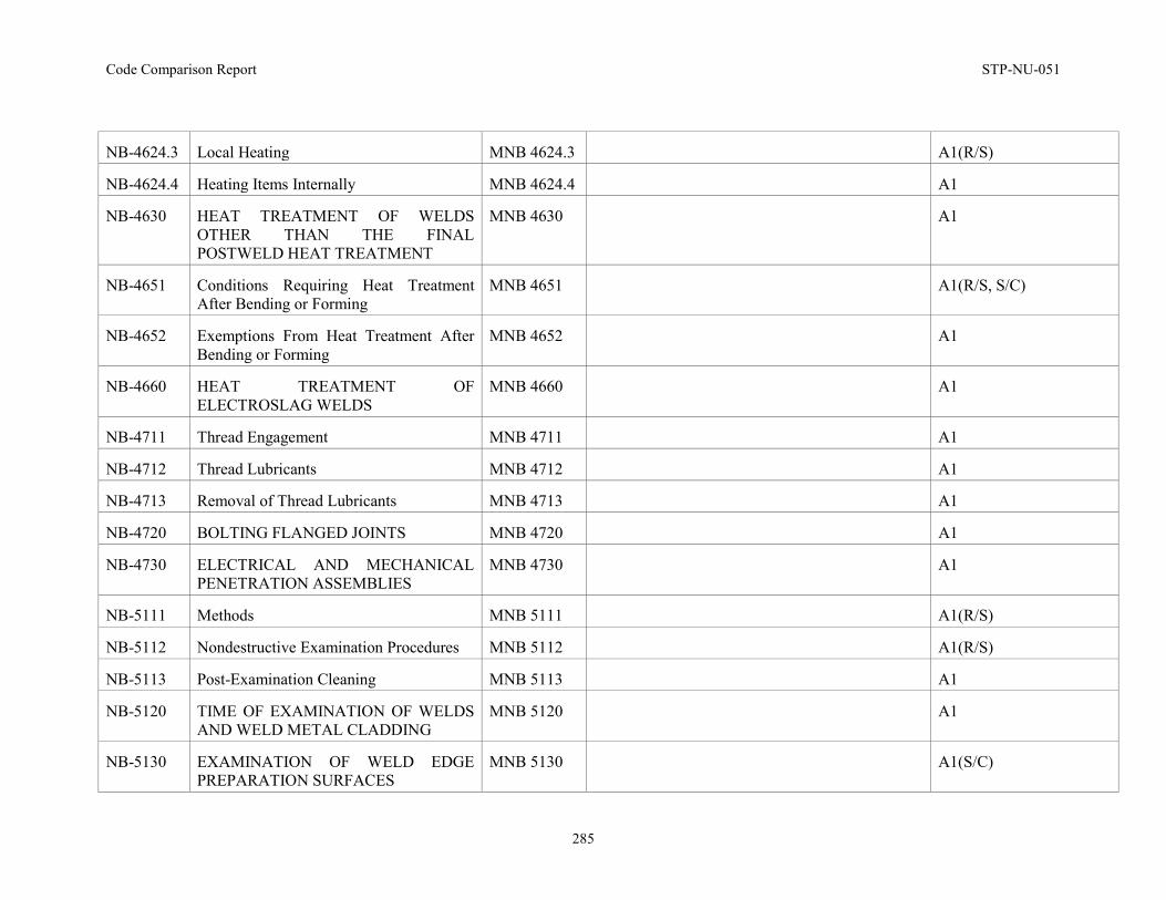
Code Comparison Report STP-NU-051
285
NB-4624.3 Local Heating MNB 4624.3 A1(R/S)
NB-4624.4 Heating Items Internally MNB 4624.4 A1
NB-4630 HEAT TREATMENT OF WELDS OTHER THAN THE FINAL POSTWELD HEAT TREATMENT
MNB 4630 A1
NB-4651 Conditions Requiring Heat Treatment After Bending or Forming
MNB 4651 A1(R/S, S/C)
NB-4652 Exemptions From Heat Treatment After Bending or Forming
MNB 4652 A1
NB-4660 HEAT TREATMENT OF ELECTROSLAG WELDS
MNB 4660 A1
NB-4711 Thread Engagement MNB 4711 A1
NB-4712 Thread Lubricants MNB 4712 A1
NB-4713 Removal of Thread Lubricants MNB 4713 A1
NB-4720 BOLTING FLANGED JOINTS MNB 4720 A1
NB-4730 ELECTRICAL AND MECHANICAL PENETRATION ASSEMBLIES
MNB 4730 A1
NB-5111 Methods MNB 5111 A1(R/S)
NB-5112 Nondestructive Examination Procedures MNB 5112 A1(R/S)
NB-5113 Post-Examination Cleaning MNB 5113 A1
NB-5120 TIME OF EXAMINATION OF WELDS AND WELD METAL CLADDING
MNB 5120 A1
NB-5130 EXAMINATION OF WELD EDGE PREPARATION SURFACES
MNB 5130 A1(S/C)
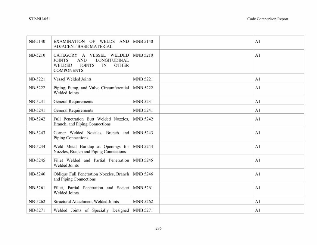
STP-NU-051 Code Comparison Report
286
NB-5140 EXAMINATION OF WELDS AND ADJACENT BASE MATERIAL
MNB 5140 A1
NB-5210 CATEGORY A VESSEL WELDED JOINTS AND LONGITUDINAL WELDED JOINTS IN OTHER COMPONENTS
MNB 5210 A1
NB-5221 Vessel Welded Joints MNB 5221 A1
NB-5222 Piping, Pump, and Valve Circumferential Welded Joints
MNB 5222 A1
NB-5231 General Requirements MNB 5231 A1
NB-5241 General Requirements MNB 5241 A1
NB-5242 Full Penetration Butt Welded Nozzles, Branch, and Piping Connections
MNB 5242 A1
NB-5243 Corner Welded Nozzles, Branch and Piping Connections
MNB 5243 A1
NB-5244 Weld Metal Buildup at Openings for Nozzles, Branch and Piping Connections
MNB 5244 A1
NB-5245 Fillet Welded and Partial Penetration Welded Joints
MNB 5245 A1
NB-5246 Oblique Full Penetration Nozzles, Branch and Piping Connections
MNB 5246 A1
NB-5261 Fillet, Partial Penetration and Socket Welded Joints
MNB 5261 A1
NB-5262 Structural Attachment Welded Joints MNB 5262 A1
NB-5271 Welded Joints of Specially Designed MNB 5271 A1
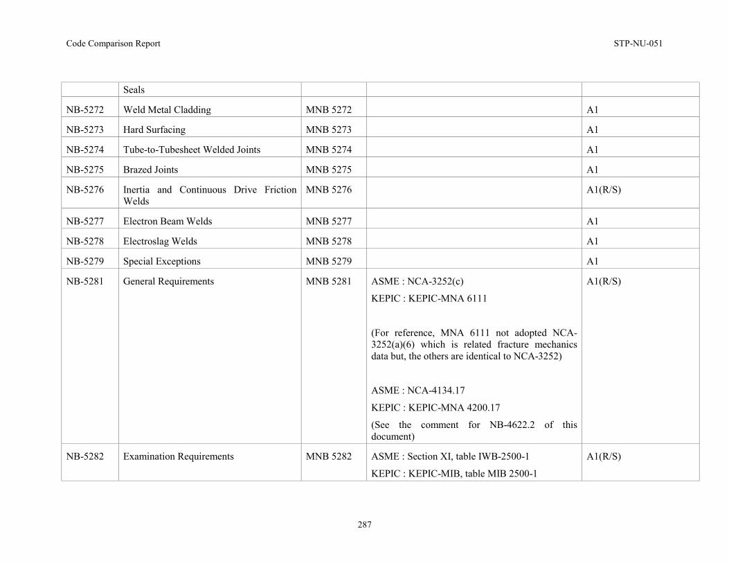
Code Comparison Report STP-NU-051
287
Seals
NB-5272 Weld Metal Cladding MNB 5272 A1
NB-5273 Hard Surfacing MNB 5273 A1
NB-5274 Tube-to-Tubesheet Welded Joints MNB 5274 A1
NB-5275 Brazed Joints MNB 5275 A1
NB-5276 Inertia and Continuous Drive Friction Welds
MNB 5276 A1(R/S)
NB-5277 Electron Beam Welds MNB 5277 A1
NB-5278 Electroslag Welds MNB 5278 A1
NB-5279 Special Exceptions MNB 5279 A1
NB-5281 General Requirements MNB 5281 ASME : NCA-3252(c)
KEPIC : KEPIC-MNA 6111
(For reference, MNA 6111 not adopted NCA-3252(a)(6) which is related fracture mechanics data but, the others are identical to NCA-3252)
ASME : NCA-4134.17
KEPIC : KEPIC-MNA 4200.17
(See the comment for NB-4622.2 of this document)
A1(R/S)
NB-5282 Examination Requirements MNB 5282 ASME : Section XI, table IWB-2500-1
KEPIC : KEPIC-MIB, table MIB 2500-1
A1(R/S)
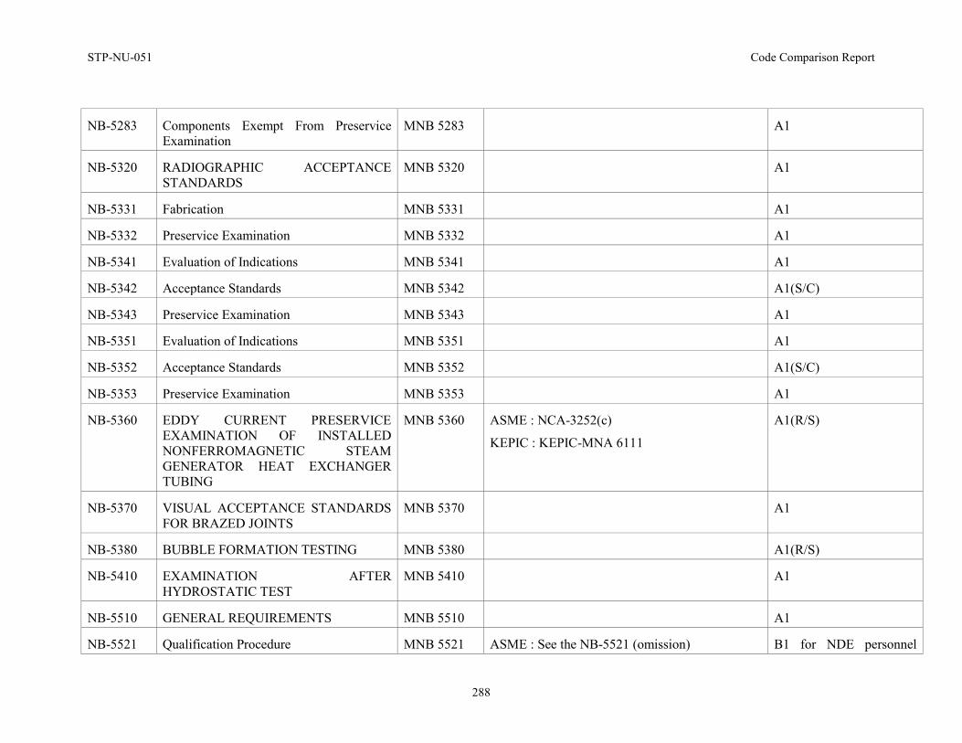
STP-NU-051 Code Comparison Report
288
NB-5283 Components Exempt From Preservice Examination
MNB 5283 A1
NB-5320 RADIOGRAPHIC ACCEPTANCE STANDARDS
MNB 5320 A1
NB-5331 Fabrication MNB 5331 A1
NB-5332 Preservice Examination MNB 5332 A1
NB-5341 Evaluation of Indications MNB 5341 A1
NB-5342 Acceptance Standards MNB 5342 A1(S/C)
NB-5343 Preservice Examination MNB 5343 A1
NB-5351 Evaluation of Indications MNB 5351 A1
NB-5352 Acceptance Standards MNB 5352 A1(S/C)
NB-5353 Preservice Examination MNB 5353 A1
NB-5360 EDDY CURRENT PRESERVICE EXAMINATION OF INSTALLED NONFERROMAGNETIC STEAM GENERATOR HEAT EXCHANGER TUBING
MNB 5360 ASME : NCA-3252(c)
KEPIC : KEPIC-MNA 6111
A1(R/S)
NB-5370 VISUAL ACCEPTANCE STANDARDS FOR BRAZED JOINTS
MNB 5370 A1
NB-5380 BUBBLE FORMATION TESTING MNB 5380 A1(R/S)
NB-5410 EXAMINATION AFTER HYDROSTATIC TEST
MNB 5410 A1
NB-5510 GENERAL REQUIREMENTS MNB 5510 A1
NB-5521 Qualification Procedure MNB 5521 ASME : See the NB-5521 (omission) B1 for NDE personnel
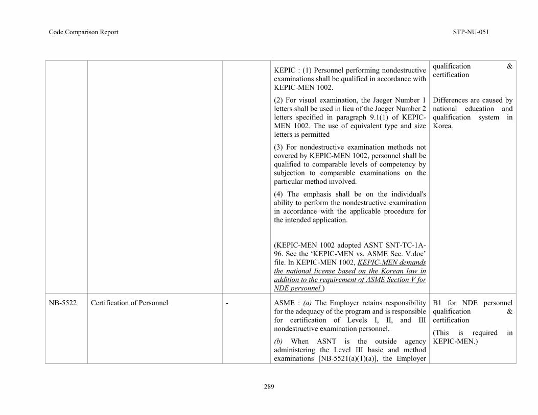
Code Comparison Report STP-NU-051
289
KEPIC : (1) Personnel performing nondestructive examinations shall be qualified in accordance with KEPIC-MEN 1002.
(2) For visual examination, the Jaeger Number 1 letters shall be used in lieu of the Jaeger Number 2 letters specified in paragraph 9.1(1) of KEPIC-MEN 1002. The use of equivalent type and size letters is permitted
(3) For nondestructive examination methods not covered by KEPIC-MEN 1002, personnel shall be qualified to comparable levels of competency by subjection to comparable examinations on the particular method involved.
(4) The emphasis shall be on the individual's ability to perform the nondestructive examination in accordance with the applicable procedure for the intended application.
(KEPIC-MEN 1002 adopted ASNT SNT-TC-1A-96. See the ‘KEPIC-MEN vs. ASME Sec. V.doc’ file. In KEPIC-MEN 1002, KEPIC-MEN demands the national license based on the Korean law in addition to the requirement of ASME Section V for NDE personnel.)
qualification & certification
Differences are caused by national education and qualification system in Korea.
NB-5522 Certification of Personnel
- ASME : (a) The Employer retains responsibility for the adequacy of the program and is responsible for certification of Levels I, II, and III nondestructive examination personnel.
(b) When ASNT is the outside agency administering the Level III basic and method examinations [NB-5521(a)(1)(a)], the Employer
B1 for NDE personnel qualification & certification
(This is required in KEPIC-MEN.)
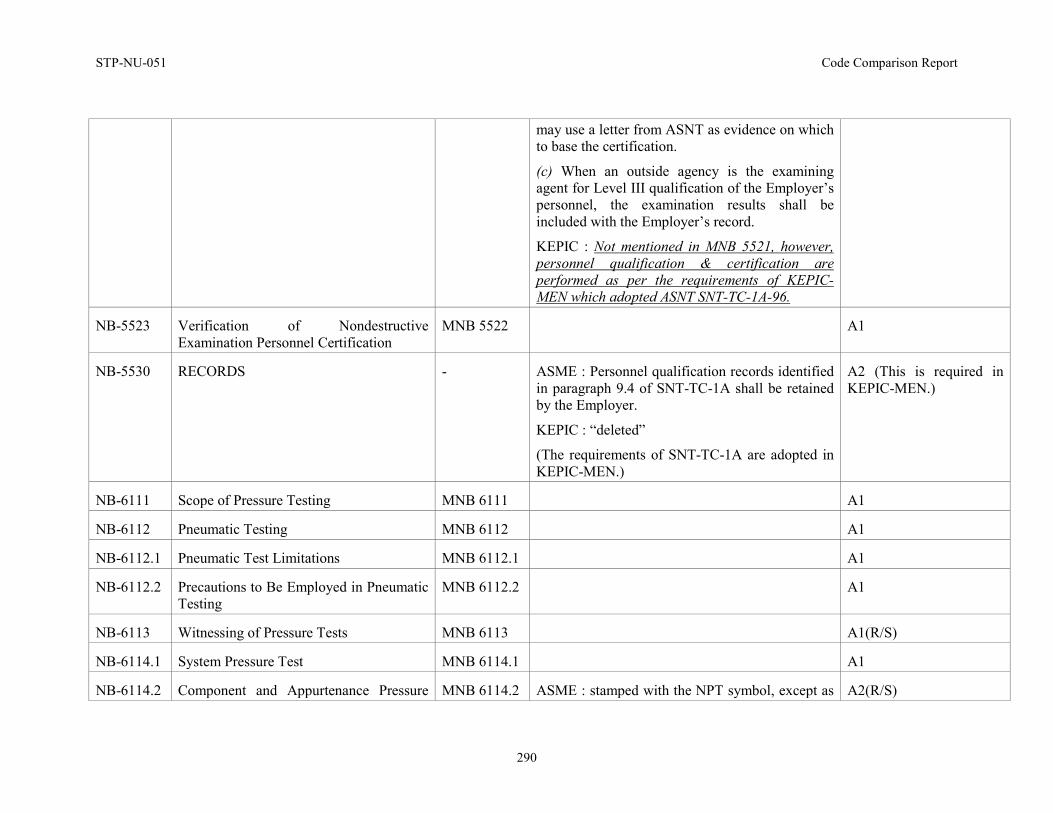
STP-NU-051 Code Comparison Report
290
may use a letter from ASNT as evidence on which to base the certification.
(c) When an outside agency is the examining agent for Level III qualification of the Employer’s personnel, the examination results shall be included with the Employer’s record.
KEPIC : Not mentioned in MNB 5521, however, personnel qualification & certification are performed as per the requirements of KEPIC-MEN which adopted ASNT SNT-TC-1A-96.
NB-5523 Verification of Nondestructive Examination Personnel Certification
MNB 5522 A1
NB-5530 RECORDS - ASME : Personnel qualification records identified in paragraph 9.4 of SNT-TC-1A shall be retained by the Employer.
KEPIC : “deleted”
(The requirements of SNT-TC-1A are adopted in KEPIC-MEN.)
A2 (This is required in KEPIC-MEN.)
NB-6111 Scope of Pressure Testing MNB 6111 A1
NB-6112 Pneumatic Testing MNB 6112 A1
NB-6112.1 Pneumatic Test Limitations MNB 6112.1 A1
NB-6112.2 Precautions to Be Employed in Pneumatic Testing
MNB 6112.2 A1
NB-6113 Witnessing of Pressure Tests MNB 6113 A1(R/S)
NB-6114.1 System Pressure Test MNB 6114.1 A1
NB-6114.2 Component and Appurtenance Pressure MNB 6114.2 ASME : stamped with the NPT symbol, except as A2(R/S)
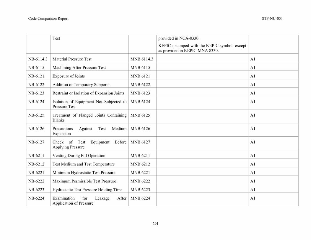
Code Comparison Report STP-NU-051
291
Test provided in NCA-8330.
KEPIC : stamped with the KEPIC symbol, except as provided in KEPIC-MNA 8330.
NB-6114.3 Material Pressure Test MNB 6114.3 A1
NB-6115 Machining After Pressure Test MNB 6115 A1
NB-6121 Exposure of Joints MNB 6121 A1
NB-6122 Addition of Temporary Supports MNB 6122 A1
NB-6123 Restraint or Isolation of Expansion Joints MNB 6123 A1
NB-6124 Isolation of Equipment Not Subjected to Pressure Test
MNB 6124 A1
NB-6125 Treatment of Flanged Joints Containing Blanks
MNB 6125 A1
NB-6126 Precautions Against Test Medium Expansion
MNB 6126 A1
NB-6127 Check of Test Equipment Before Applying Pressure
MNB 6127 A1
NB-6211 Venting During Fill Operation MNB 6211 A1
NB-6212 Test Medium and Test Temperature MNB 6212 A1
NB-6221 Minimum Hydrostatic Test Pressure MNB 6221 A1
NB-6222 Maximum Permissible Test Pressure MNB 6222 A1
NB-6223 Hydrostatic Test Pressure Holding Time MNB 6223 A1
NB-6224 Examination for Leakage After Application of Pressure
MNB 6224 A1
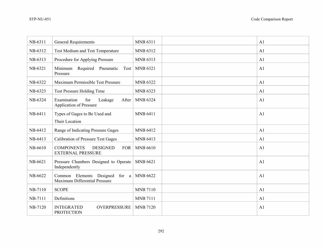
STP-NU-051 Code Comparison Report
292
NB-6311 General Requirements MNB 6311 A1
NB-6312 Test Medium and Test Temperature MNB 6312 A1
NB-6313 Procedure for Applying Pressure MNB 6313 A1
NB-6321 Minimum Required Pneumatic Test Pressure
MNB 6321 A1
NB-6322 Maximum Permissible Test Pressure MNB 6322 A1
NB-6323 Test Pressure Holding Time MNB 6323 A1
NB-6324 Examination for Leakage After Application of Pressure
MNB 6324 A1
NB-6411 Types of Gages to Be Used and
Their Location
MNB 6411 A1
NB-6412 Range of Indicating Pressure Gages MNB 6412 A1
NB-6413 Calibration of Pressure Test Gages MNB 6413 A1
NB-6610 COMPONENTS DESIGNED FOR EXTERNAL PRESSURE
MNB 6610 A1
NB-6621 Pressure Chambers Designed to Operate Independently
MNB 6621 A1
NB-6622 Common Elements Designed for a Maximum Differential Pressure
MNB 6622 A1
NB-7110 SCOPE MNB 7110 A1
NB-7111 Definitions MNB 7111 A1
NB-7120 INTEGRATED OVERPRESSURE PROTECTION
MNB 7120 A1
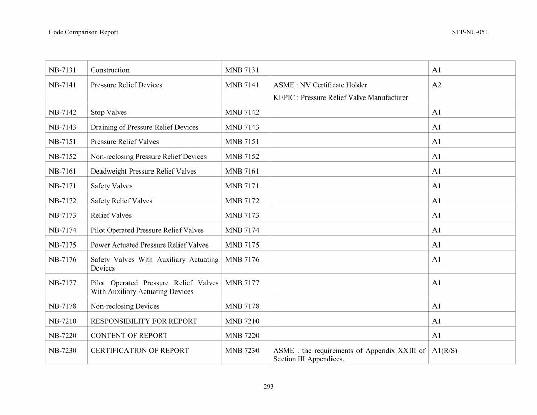
Code Comparison Report STP-NU-051
293
NB-7131 Construction MNB 7131 A1
NB-7141 Pressure Relief Devices
MNB 7141 ASME : NV Certificate Holder
KEPIC : Pressure Relief Valve Manufacturer
A2
NB-7142 Stop Valves MNB 7142 A1
NB-7143 Draining of Pressure Relief Devices MNB 7143 A1
NB-7151 Pressure Relief Valves MNB 7151 A1
NB-7152 Non-reclosing Pressure Relief Devices MNB 7152 A1
NB-7161 Deadweight Pressure Relief Valves MNB 7161 A1
NB-7171 Safety Valves MNB 7171 A1
NB-7172 Safety Relief Valves MNB 7172 A1
NB-7173 Relief Valves MNB 7173 A1
NB-7174 Pilot Operated Pressure Relief Valves MNB 7174 A1
NB-7175 Power Actuated Pressure Relief Valves MNB 7175 A1
NB-7176 Safety Valves With Auxiliary Actuating Devices
MNB 7176 A1
NB-7177 Pilot Operated Pressure Relief Valves With Auxiliary Actuating Devices
MNB 7177 A1
NB-7178 Non-reclosing Devices MNB 7178 A1
NB-7210 RESPONSIBILITY FOR REPORT MNB 7210 A1
NB-7220 CONTENT OF REPORT MNB 7220 A1
NB-7230 CERTIFICATION OF REPORT MNB 7230 ASME : the requirements of Appendix XXIII of Section III Appendices.
A1(R/S)
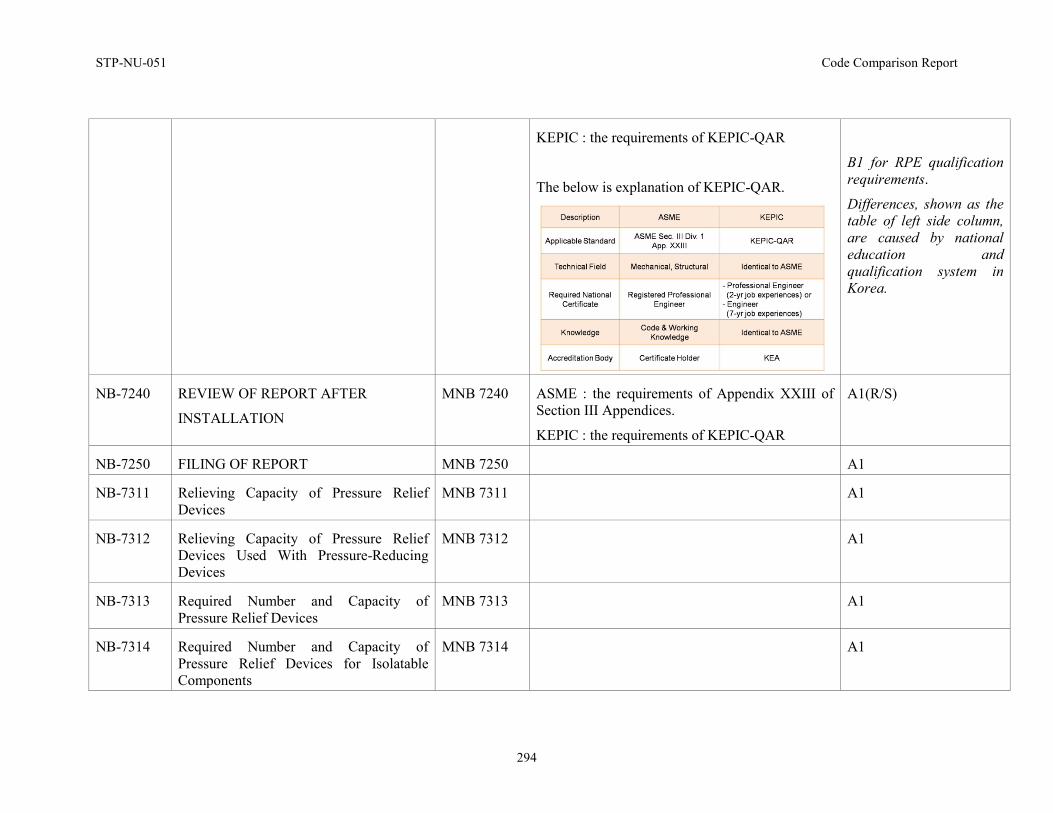
STP-NU-051 Code Comparison Report
294
KEPIC : the requirements of KEPIC-QAR
The below is explanation of KEPIC-QAR.
B1 for RPE qualification requirements.
Differences, shown as the table of left side column, are caused by national education and qualification system in Korea.
NB-7240 REVIEW OF REPORT AFTER
INSTALLATION
MNB 7240 ASME : the requirements of Appendix XXIII of Section III Appendices.
KEPIC : the requirements of KEPIC-QAR
A1(R/S)
NB-7250 FILING OF REPORT MNB 7250 A1
NB-7311 Relieving Capacity of Pressure Relief Devices
MNB 7311 A1
NB-7312 Relieving Capacity of Pressure Relief Devices Used With Pressure-Reducing Devices
MNB 7312 A1
NB-7313 Required Number and Capacity of Pressure Relief Devices
MNB 7313 A1
NB-7314 Required Number and Capacity of Pressure Relief Devices for Isolatable Components
MNB 7314 A1
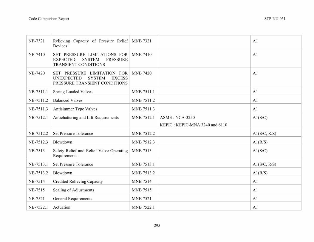
Code Comparison Report STP-NU-051
295
NB-7321 Relieving Capacity of Pressure Relief Devices
MNB 7321 A1
NB-7410 SET PRESSURE LIMITATIONS FOR EXPECTED SYSTEM PRESSURE TRANSIENT CONDITIONS
MNB 7410 A1
NB-7420 SET PRESSURE LIMITATION FOR UNEXPECTED SYSTEM EXCESS PRESSURE TRANSIENT CONDITIONS
MNB 7420 A1
NB-7511.1 Spring-Loaded Valves MNB 7511.1 A1
NB-7511.2 Balanced Valves MNB 7511.2 A1
NB-7511.3 Antisimmer Type Valves MNB 7511.3 A1
NB-7512.1 Antichattering and Lift Requirements MNB 7512.1 ASME : NCA-3250
KEPIC : KEPIC-MNA 3240 and 6110
A1(S/C)
NB-7512.2 Set Pressure Tolerance MNB 7512.2 A1(S/C, R/S)
NB-7512.3 Blowdown MNB 7512.3 A1(R/S)
NB-7513 Safety Relief and Relief Valve Operating Requirements
MNB 7513 A1(S/C)
NB-7513.1 Set Pressure Tolerance MNB 7513.1 A1(S/C, R/S)
NB-7513.2 Blowdown MNB 7513.2 A1(R/S)
NB-7514 Credited Relieving Capacity MNB 7514 A1
NB-7515 Sealing of Adjustments MNB 7515 A1
NB-7521 General Requirements MNB 7521 A1
NB-7522.1 Actuation MNB 7522.1 A1
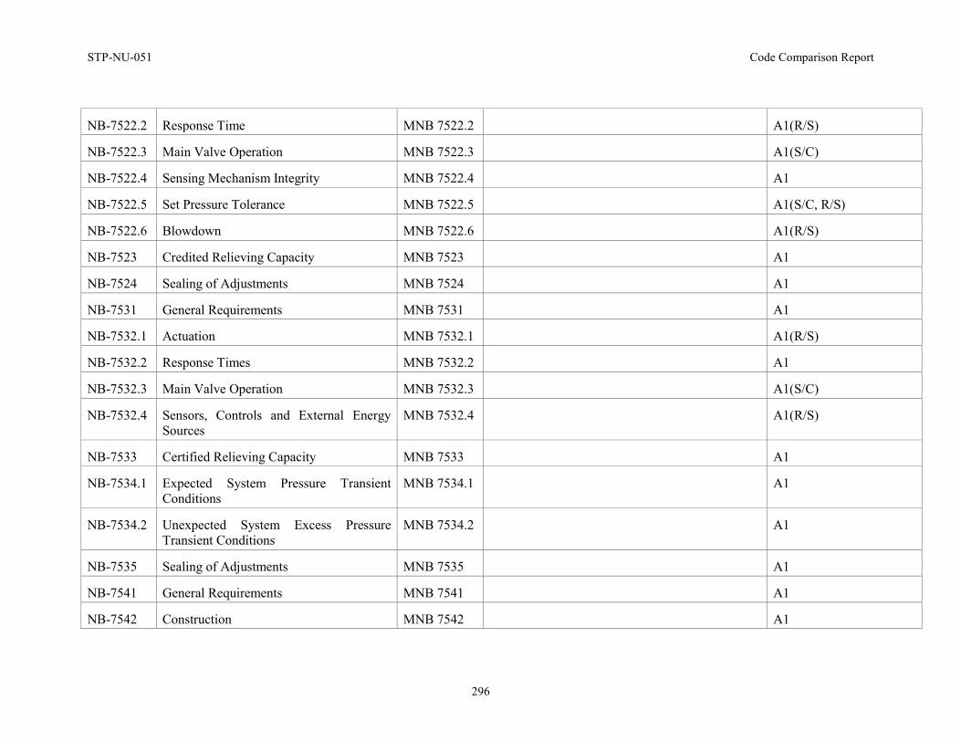
STP-NU-051 Code Comparison Report
296
NB-7522.2 Response Time MNB 7522.2 A1(R/S)
NB-7522.3 Main Valve Operation MNB 7522.3 A1(S/C)
NB-7522.4 Sensing Mechanism Integrity MNB 7522.4 A1
NB-7522.5 Set Pressure Tolerance MNB 7522.5 A1(S/C, R/S)
NB-7522.6 Blowdown MNB 7522.6 A1(R/S)
NB-7523 Credited Relieving Capacity MNB 7523 A1
NB-7524 Sealing of Adjustments MNB 7524 A1
NB-7531 General Requirements MNB 7531 A1
NB-7532.1 Actuation MNB 7532.1 A1(R/S)
NB-7532.2 Response Times MNB 7532.2 A1
NB-7532.3 Main Valve Operation MNB 7532.3 A1(S/C)
NB-7532.4 Sensors, Controls and External Energy Sources
MNB 7532.4 A1(R/S)
NB-7533 Certified Relieving Capacity MNB 7533 A1
NB-7534.1 Expected System Pressure Transient Conditions
MNB 7534.1 A1
NB-7534.2 Unexpected System Excess Pressure Transient Conditions
MNB 7534.2 A1
NB-7535 Sealing of Adjustments MNB 7535 A1
NB-7541 General Requirements MNB 7541 A1
NB-7542 Construction MNB 7542 A1
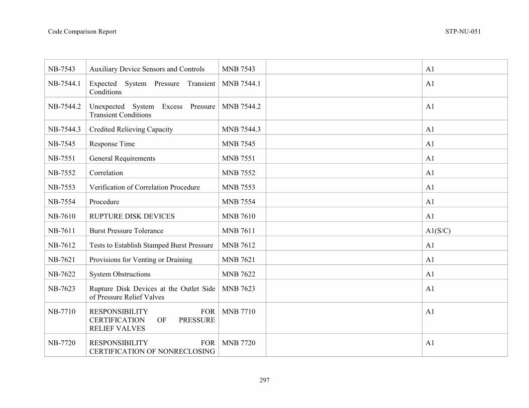
Code Comparison Report STP-NU-051
297
NB-7543 Auxiliary Device Sensors and Controls MNB 7543 A1
NB-7544.1 Expected System Pressure Transient Conditions
MNB 7544.1 A1
NB-7544.2 Unexpected System Excess Pressure Transient Conditions
MNB 7544.2 A1
NB-7544.3 Credited Relieving Capacity MNB 7544.3 A1
NB-7545 Response Time MNB 7545 A1
NB-7551 General Requirements MNB 7551 A1
NB-7552 Correlation MNB 7552 A1
NB-7553 Verification of Correlation Procedure MNB 7553 A1
NB-7554 Procedure MNB 7554 A1
NB-7610 RUPTURE DISK DEVICES MNB 7610 A1
NB-7611 Burst Pressure Tolerance MNB 7611 A1(S/C)
NB-7612 Tests to Establish Stamped Burst Pressure MNB 7612 A1
NB-7621 Provisions for Venting or Draining MNB 7621 A1
NB-7622 System Obstructions MNB 7622 A1
NB-7623 Rupture Disk Devices at the Outlet Side of Pressure Relief Valves
MNB 7623 A1
NB-7710 RESPONSIBILITY FOR CERTIFICATION OF PRESSURE RELIEF VALVES
MNB 7710 A1
NB-7720 RESPONSIBILITY FOR CERTIFICATION OF NONRECLOSING
MNB 7720 A1
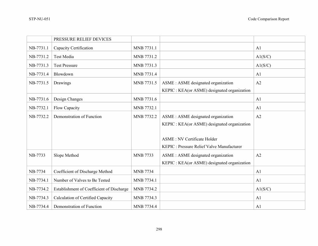
STP-NU-051 Code Comparison Report
298
PRESSURE RELIEF DEVICES
NB-7731.1 Capacity Certification MNB 7731.1 A1
NB-7731.2 Test Media MNB 7731.2 A1(S/C)
NB-7731.3 Test Pressure MNB 7731.3 A1(S/C)
NB-7731.4 Blowdown MNB 7731.4 A1
NB-7731.5 Drawings MNB 7731.5 ASME : ASME designated organization
KEPIC : KEA(or ASME) designated organization
A2
NB-7731.6 Design Changes MNB 7731.6 A1
NB-7732.1 Flow Capacity MNB 7732.1 A1
NB-7732.2 Demonstration of Function MNB 7732.2 ASME : ASME designated organization
KEPIC : KEA(or ASME) designated organization
ASME : NV Certificate Holder
KEPIC : Pressure Relief Valve Manufacturer
A2
NB-7733 Slope Method MNB 7733 ASME : ASME designated organization
KEPIC : KEA(or ASME) designated organization
A2
NB-7734 Coefficient of Discharge Method MNB 7734 A1
NB-7734.1 Number of Valves to Be Tested MNB 7734.1 A1
NB-7734.2 Establishment of Coefficient of Discharge MNB 7734.2 A1(S/C)
NB-7734.3 Calculation of Certified Capacity MNB 7734.3 A1
NB-7734.4 Demonstration of Function MNB 7734.4 A1
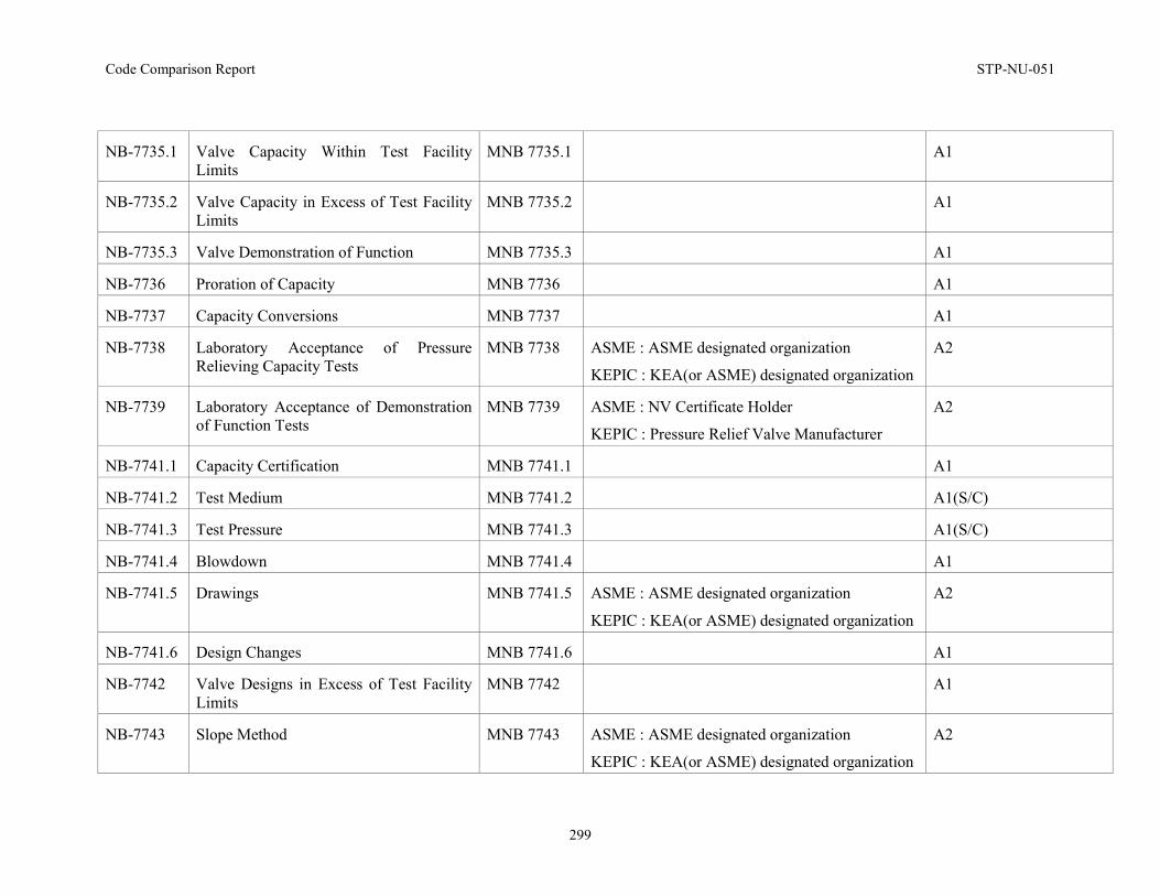
Code Comparison Report STP-NU-051
299
NB-7735.1 Valve Capacity Within Test Facility Limits
MNB 7735.1 A1
NB-7735.2 Valve Capacity in Excess of Test Facility Limits
MNB 7735.2 A1
NB-7735.3 Valve Demonstration of Function MNB 7735.3 A1
NB-7736 Proration of Capacity MNB 7736 A1
NB-7737 Capacity Conversions MNB 7737 A1
NB-7738 Laboratory Acceptance of Pressure Relieving Capacity Tests
MNB 7738 ASME : ASME designated organization
KEPIC : KEA(or ASME) designated organization
A2
NB-7739 Laboratory Acceptance of Demonstration of Function Tests
MNB 7739 ASME : NV Certificate Holder
KEPIC : Pressure Relief Valve Manufacturer
A2
NB-7741.1 Capacity Certification MNB 7741.1 A1
NB-7741.2 Test Medium MNB 7741.2 A1(S/C)
NB-7741.3 Test Pressure MNB 7741.3 A1(S/C)
NB-7741.4 Blowdown MNB 7741.4 A1
NB-7741.5 Drawings MNB 7741.5 ASME : ASME designated organization
KEPIC : KEA(or ASME) designated organization
A2
NB-7741.6 Design Changes MNB 7741.6 A1
NB-7742 Valve Designs in Excess of Test Facility Limits
MNB 7742 A1
NB-7743 Slope Method MNB 7743 ASME : ASME designated organization
KEPIC : KEA(or ASME) designated organization
A2
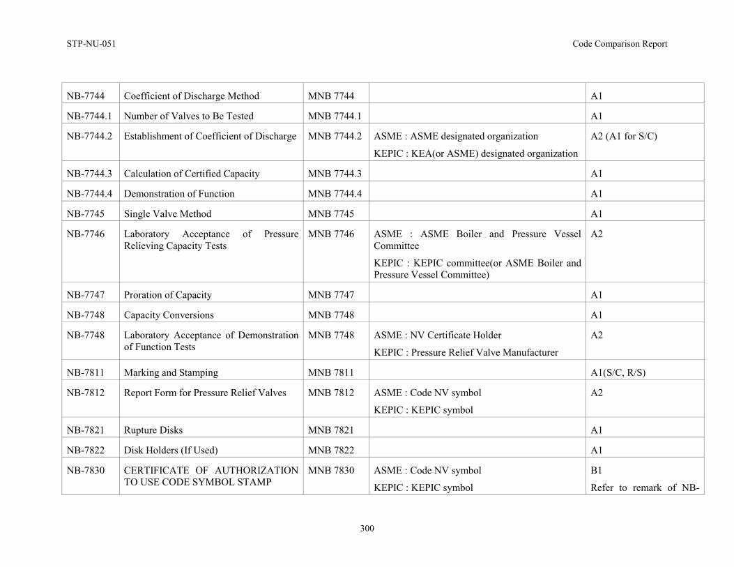
STP-NU-051 Code Comparison Report
300
NB-7744 Coefficient of Discharge Method MNB 7744 A1
NB-7744.1 Number of Valves to Be Tested MNB 7744.1 A1
NB-7744.2 Establishment of Coefficient of Discharge MNB 7744.2 ASME : ASME designated organization
KEPIC : KEA(or ASME) designated organization
A2 (A1 for S/C)
NB-7744.3 Calculation of Certified Capacity MNB 7744.3 A1
NB-7744.4 Demonstration of Function MNB 7744.4 A1
NB-7745 Single Valve Method MNB 7745 A1
NB-7746 Laboratory Acceptance of Pressure Relieving Capacity Tests
MNB 7746 ASME : ASME Boiler and Pressure Vessel Committee
KEPIC : KEPIC committee(or ASME Boiler and Pressure Vessel Committee)
A2
NB-7747 Proration of Capacity MNB 7747 A1
NB-7748 Capacity Conversions MNB 7748 A1
NB-7748 Laboratory Acceptance of Demonstration of Function Tests
MNB 7748 ASME : NV Certificate Holder
KEPIC : Pressure Relief Valve Manufacturer
A2
NB-7811 Marking and Stamping MNB 7811 A1(S/C, R/S)
NB-7812 Report Form for Pressure Relief Valves MNB 7812 ASME : Code NV symbol
KEPIC : KEPIC symbol
A2
NB-7821 Rupture Disks MNB 7821 A1
NB-7822 Disk Holders (If Used) MNB 7822 A1
NB-7830 CERTIFICATE OF AUTHORIZATION TO USE CODE SYMBOL STAMP
MNB 7830 ASME : Code NV symbol
KEPIC : KEPIC symbol
B1
Refer to remark of NB-
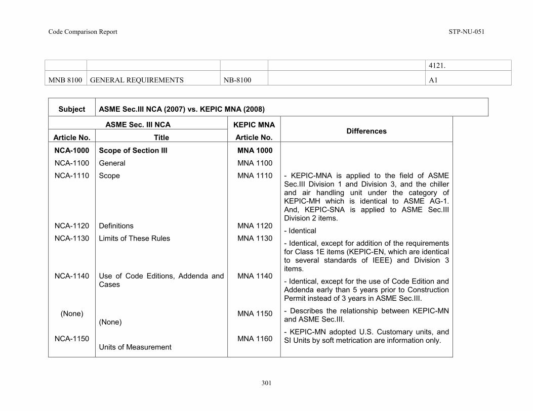
Code Comparison Report STP-NU-051
301
4121.
MNB 8100 GENERAL REQUIREMENTS NB-8100 A1
Subject ASME Sec.III NCA (2007) vs. KEPIC MNA (2008)
ASME Sec. III NCA KEPIC MNA Article No.
Differences Article No. Title NCA-1000 NCA-1100
NCA-1110
NCA-1120
NCA-1130
NCA-1140
(None)
NCA-1150
Scope of Section III General
Scope
Definitions
Limits of These Rules
Use of Code Editions, Addenda and Cases
(None)
Units of Measurement
MNA 1000 MNA 1100
MNA 1110
MNA 1120
MNA 1130
MNA 1140
MNA 1150
MNA 1160
- KEPIC-MNA is applied to the field of ASME Sec.III Division 1 and Division 3, and the chiller and air handling unit under the category of KEPIC-MH which is identical to ASME AG-1. And, KEPIC-SNA is applied to ASME Sec.III Division 2 items.
- Identical
- Identical, except for addition of the requirements for Class 1E items (KEPIC-EN, which are identical to several standards of IEEE) and Division 3 items.
- Identical, except for the use of Code Edition and Addenda early than 5 years prior to Construction Permit instead of 3 years in ASME Sec.III.
- Describes the relationship between KEPIC-MN and ASME Sec.III.
- KEPIC-MN adopted U.S. Customary units, and SI Units by soft metrication are information only.
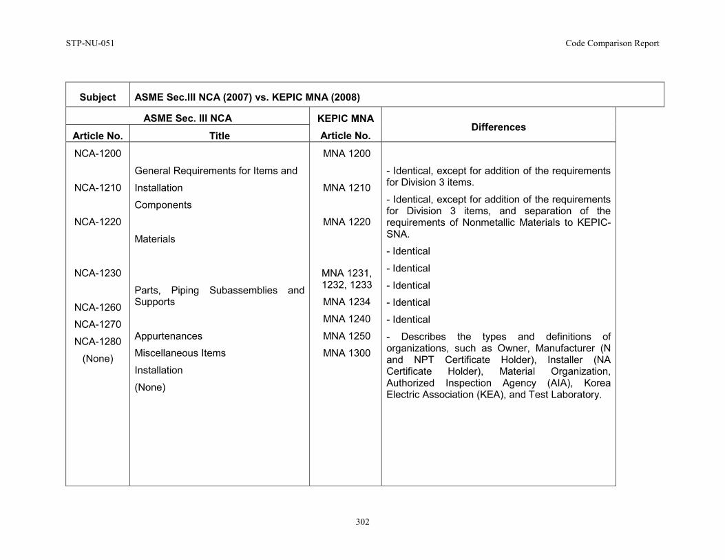
STP-NU-051 Code Comparison Report
302
Subject ASME Sec.III NCA (2007) vs. KEPIC MNA (2008)
ASME Sec. III NCA KEPIC MNA Article No.
Differences Article No. Title
NCA-1200
NCA-1210
NCA-1220
NCA-1230
NCA-1260
NCA-1270
NCA-1280
(None)
General Requirements for Items and
Installation
Components
Materials
Parts, Piping Subassemblies and Supports
Appurtenances
Miscellaneous Items
Installation
(None)
MNA 1200
MNA 1210
MNA 1220
MNA 1231, 1232, 1233
MNA 1234
MNA 1240
MNA 1250
MNA 1300
- Identical, except for addition of the requirements for Division 3 items.
- Identical, except for addition of the requirements for Division 3 items, and separation of the requirements of Nonmetallic Materials to KEPIC-SNA.
- Identical
- Identical
- Identical
- Identical
- Identical
- Describes the types and definitions of organizations, such as Owner, Manufacturer (N and NPT Certificate Holder), Installer (NA Certificate Holder), Material Organization, Authorized Inspection Agency (AIA), Korea Electric Association (KEA), and Test Laboratory.
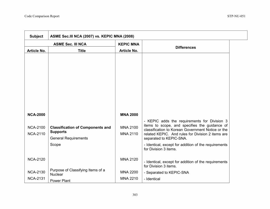
Code Comparison Report STP-NU-051
303
Subject ASME Sec.III NCA (2007) vs. KEPIC MNA (2008)
ASME Sec. III NCA KEPIC MNA Article No.
Differences Article No. Title
NCA-2000
NCA-2100
NCA-2110
NCA-2120
NCA-2130
NCA-2131
Classification of Components and Supports General Requirements
Scope
Purpose of Classifying Items of a Nuclear
Power Plant
MNA 2000
MNA 2100
MNA 2110
MNA 2120
MNA 2200
MNA 2210
- KEPIC adds the requirements for Division 3 items to scope, and specifies the guidance of classification to Korean Government Notice or the related KEPIC. And rules for Division 2 items are separated to KEPIC-SNA.
- Identical, except for addition of the requirements for Division 3 items.
- Identical, except for addition of the requirements for Division 3 items.
- Separated to KEPIC-SNA
- Identical
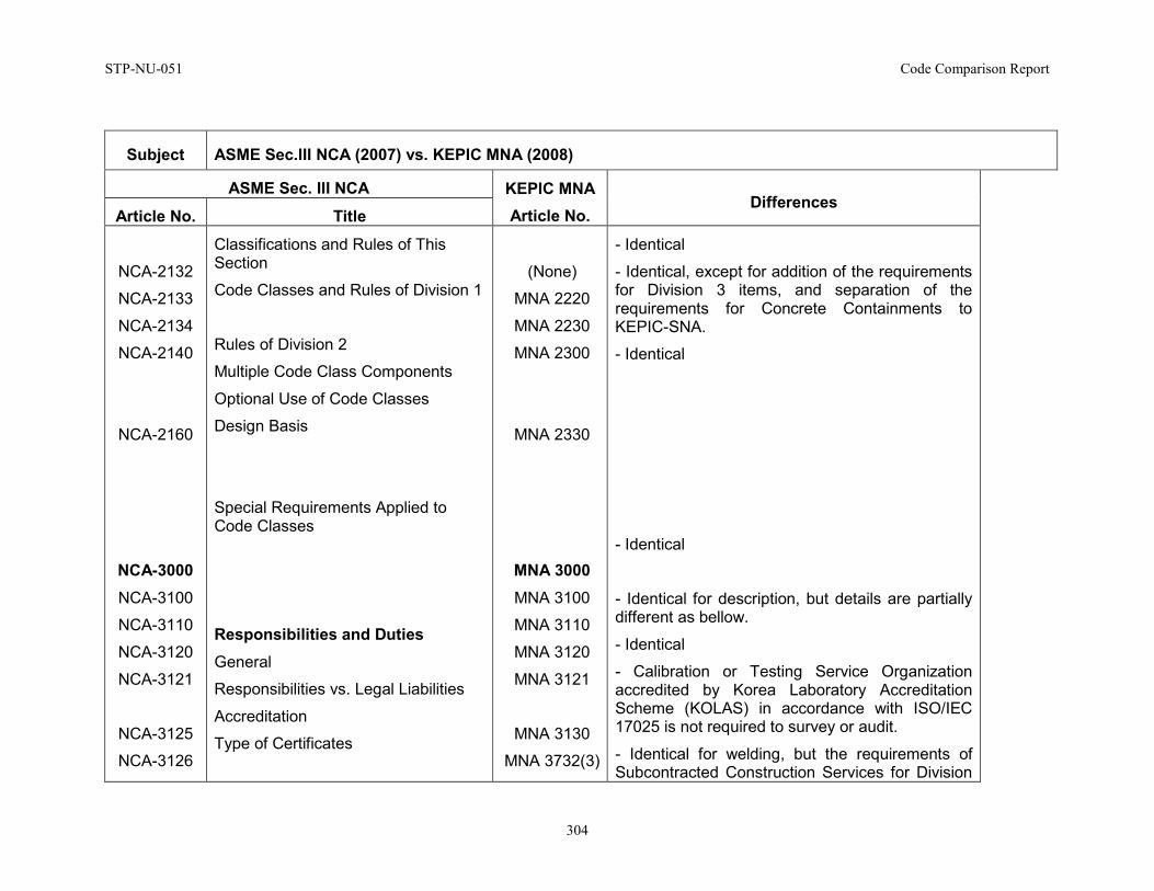
STP-NU-051 Code Comparison Report
304
Subject ASME Sec.III NCA (2007) vs. KEPIC MNA (2008)
ASME Sec. III NCA KEPIC MNA Article No.
Differences Article No. Title
NCA-2132
NCA-2133
NCA-2134
NCA-2140
NCA-2160
NCA-3000 NCA-3100
NCA-3110
NCA-3120
NCA-3121
NCA-3125
NCA-3126
Classifications and Rules of This Section
Code Classes and Rules of Division 1
Rules of Division 2
Multiple Code Class Components
Optional Use of Code Classes
Design Basis
Special Requirements Applied to Code Classes
Responsibilities and Duties General
Responsibilities vs. Legal Liabilities
Accreditation
Type of Certificates
(None)
MNA 2220
MNA 2230
MNA 2300
MNA 2330
MNA 3000 MNA 3100
MNA 3110
MNA 3120
MNA 3121
MNA 3130
MNA 3732(3)
- Identical
- Identical, except for addition of the requirements for Division 3 items, and separation of the requirements for Concrete Containments to KEPIC-SNA.
- Identical
- Identical
- Identical for description, but details are partially different as bellow.
- Identical
- Calibration or Testing Service Organization accredited by Korea Laboratory Accreditation Scheme (KOLAS) in accordance with ISO/IEC 17025 is not required to survey or audit.
- Identical for welding, but the requirements of Subcontracted Construction Services for Division
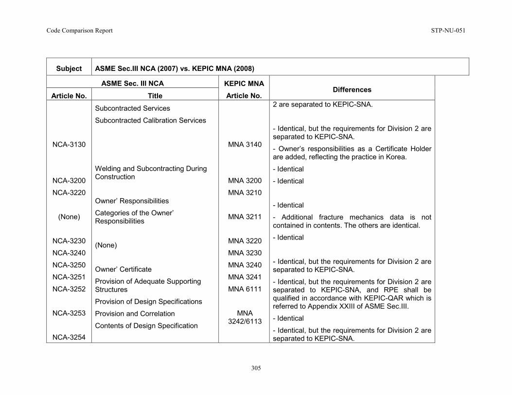
Code Comparison Report STP-NU-051
305
Subject ASME Sec.III NCA (2007) vs. KEPIC MNA (2008)
ASME Sec. III NCA KEPIC MNA Article No.
Differences Article No. Title
NCA-3130
NCA-3200
NCA-3220
(None)
NCA-3230
NCA-3240
NCA-3250
NCA-3251
NCA-3252
NCA-3253
NCA-3254
Subcontracted Services
Subcontracted Calibration Services
Welding and Subcontracting During Construction
Owner’ Responsibilities
Categories of the Owner’ Responsibilities
(None)
Owner’ Certificate
Provision of Adequate Supporting Structures
Provision of Design Specifications
Provision and Correlation
Contents of Design Specification
MNA 3140
MNA 3200
MNA 3210
MNA 3211
MNA 3220
MNA 3230
MNA 3240
MNA 3241
MNA 6111
MNA 3242/6113
2 are separated to KEPIC-SNA.
- Identical, but the requirements for Division 2 are separated to KEPIC-SNA.
- Owner’s responsibilities as a Certificate Holder are added, reflecting the practice in Korea.
- Identical
- Identical
- Identical
- Additional fracture mechanics data is not contained in contents. The others are identical.
- Identical
- Identical, but the requirements for Division 2 are separated to KEPIC-SNA.
- Identical, but the requirements for Division 2 are separated to KEPIC-SNA, and RPE shall be qualified in accordance with KEPIC-QAR which is referred to Appendix XXIII of ASME Sec.III.
- Identical
- Identical, but the requirements for Division 2 are separated to KEPIC-SNA.
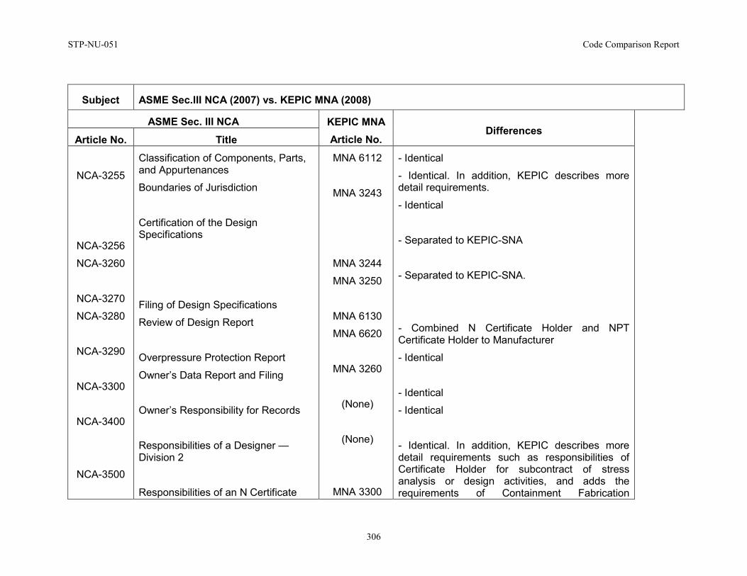
STP-NU-051 Code Comparison Report
306
Subject ASME Sec.III NCA (2007) vs. KEPIC MNA (2008)
ASME Sec. III NCA KEPIC MNA Article No.
Differences Article No. Title
NCA-3255
NCA-3256
NCA-3260
NCA-3270
NCA-3280
NCA-3290
NCA-3300
NCA-3400
NCA-3500
Classification of Components, Parts, and Appurtenances
Boundaries of Jurisdiction
Certification of the Design Specifications
Filing of Design Specifications
Review of Design Report
Overpressure Protection Report
Owner’s Data Report and Filing
Owner’s Responsibility for Records
Responsibilities of a Designer —Division 2
Responsibilities of an N Certificate
MNA 6112
MNA 3243
MNA 3244
MNA 3250
MNA 6130
MNA 6620
MNA 3260
(None)
(None)
MNA 3300
- Identical
- Identical. In addition, KEPIC describes more detail requirements.
- Identical
- Separated to KEPIC-SNA
- Separated to KEPIC-SNA.
- Combined N Certificate Holder and NPT Certificate Holder to Manufacturer
- Identical
- Identical
- Identical
- Identical. In addition, KEPIC describes more detail requirements such as responsibilities of Certificate Holder for subcontract of stress analysis or design activities, and adds the requirements of Containment Fabrication
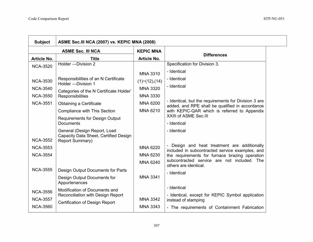
Code Comparison Report STP-NU-051
307
Subject ASME Sec.III NCA (2007) vs. KEPIC MNA (2008)
ASME Sec. III NCA KEPIC MNA Article No.
Differences Article No. Title
NCA-3520
NCA-3530
NCA-3540
NCA-3550
NCA-3551
NCA-3552
NCA-3553
NCA-3554
NCA-3555
NCA-3556
NCA-3557
NCA-3560
Holder —Division 2
Responsibilities of an N Certificate Holder —Division 1
Categories of the N Certificate Holder’ Responsibilities
Obtaining a Certificate
Compliance with This Section
Requirements for Design Output Documents
General (Design Report, Load Capacity Data Sheet, Certified Design Report Summary)
Design Output Documents for Parts
Design Output Documents for Appurtenances
Modification of Documents and Reconciliation with Design Report
Certification of Design Report
MNA 3310
(1)~(12),(14)
MNA 3320
MNA 3330
MNA 6200
MNA 6210
MNA 6220
MNA 6230
MNA 6240
MNA 3341
MNA 3342
MNA 3343
Specification for Division 3.
- Identical
- Identical
- Identical
- Identical, but the requirements for Division 3 are added, and RPE shall be qualified in accordance with KEPIC-QAR which is referred to Appendix XXIII of ASME Sec.III
- Identical
- Identical
- Design and heat treatment are additionally included in subcontracted service examples, and the requirements for furnace brazing operation subcontracted service are not included. The others are identical.
- Identical
- Identical
- Identical, except for KEPIC Symbol application instead of stamping
- The requirements of Containment Fabrication
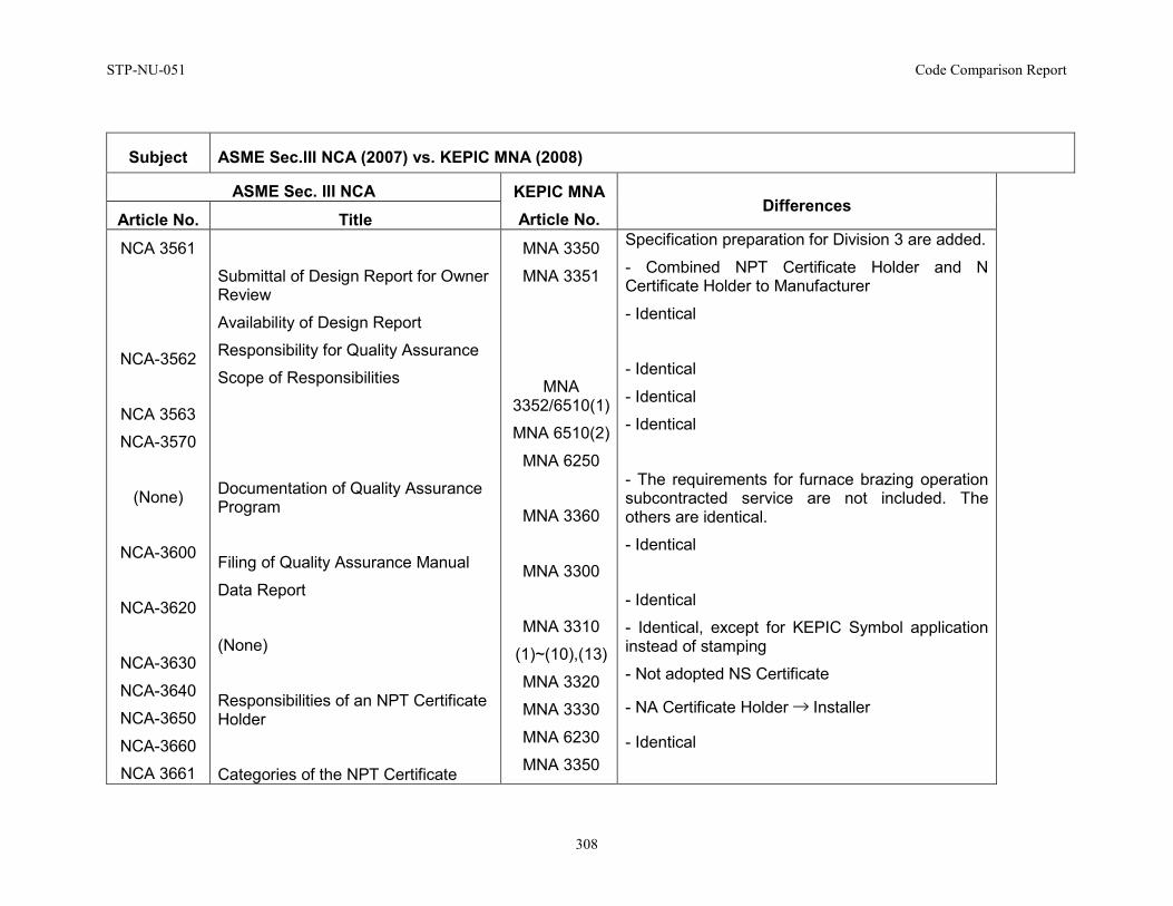
STP-NU-051 Code Comparison Report
308
Subject ASME Sec.III NCA (2007) vs. KEPIC MNA (2008)
ASME Sec. III NCA KEPIC MNA Article No.
Differences Article No. Title
NCA 3561
NCA-3562
NCA 3563
NCA-3570
(None)
NCA-3600
NCA-3620
NCA-3630
NCA-3640
NCA-3650
NCA-3660
NCA 3661
Submittal of Design Report for Owner Review
Availability of Design Report
Responsibility for Quality Assurance
Scope of Responsibilities
Documentation of Quality Assurance Program
Filing of Quality Assurance Manual
Data Report
(None)
Responsibilities of an NPT Certificate Holder
Categories of the NPT Certificate
MNA 3350
MNA 3351
MNA 3352/6510(1)
MNA 6510(2)
MNA 6250
MNA 3360
MNA 3300
MNA 3310
(1)~(10),(13)
MNA 3320
MNA 3330
MNA 6230
MNA 3350
Specification preparation for Division 3 are added.
- Combined NPT Certificate Holder and N Certificate Holder to Manufacturer
- Identical
- Identical
- Identical
- Identical
- The requirements for furnace brazing operation subcontracted service are not included. The others are identical.
- Identical
- Identical
- Identical, except for KEPIC Symbol application instead of stamping
- Not adopted NS Certificate
- NA Certificate Holder → Installer
- Identical
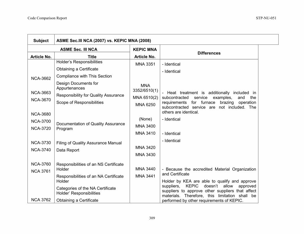
Code Comparison Report STP-NU-051
309
Subject ASME Sec.III NCA (2007) vs. KEPIC MNA (2008)
ASME Sec. III NCA KEPIC MNA Article No.
Differences Article No. Title
NCA-3662
NCA-3663
NCA-3670
NCA-3680
NCA-3700
NCA-3720
NCA-3730
NCA-3740
NCA-3760
NCA 3761
NCA 3762
Holder’s Responsibilities
Obtaining a Certificate
Compliance with This Section
Design Documents for Appurtenances
Responsibility for Quality Assurance
Scope of Responsibilities
Documentation of Quality Assurance Program
Filing of Quality Assurance Manual
Data Report
Responsibilities of an NS Certificate Holder
Responsibilities of an NA Certificate Holder
Categories of the NA Certificate Holder’ Responsibilities
Obtaining a Certificate
MNA 3351
MNA 3352/6510(1)
MNA 6510(2)
MNA 6250
(None)
MNA 3400
MNA 3410
MNA 3420
MNA 3430
MNA 3440
MNA 3441
- Identical
- Identical
- Heat treatment is additionally included in subcontracted service examples, and the requirements for furnace brazing operation subcontracted service are not included. The others are identical.
- Identical
- Identical
- Identical
- Because the accredited Material Organization and Certificate
Holder by KEA are able to qualify and approve suppliers, KEPIC doesn’t allow approved suppliers to approve other suppliers that affect materials. Therefore, this limitation shall be performed by other requirements of KEPIC.
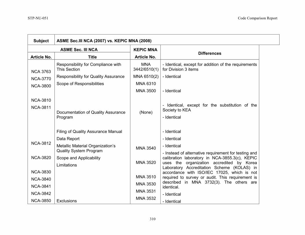
STP-NU-051 Code Comparison Report
310
Subject ASME Sec.III NCA (2007) vs. KEPIC MNA (2008)
ASME Sec. III NCA KEPIC MNA Article No.
Differences Article No. Title
NCA 3763
NCA-3770
NCA-3800
NCA-3810
NCA-3811
NCA-3812
NCA-3820
NCA-3830
NCA-3840
NCA-3841
NCA-3842
NCA-3850
Responsibility for Compliance with This Section
Responsibility for Quality Assurance
Scope of Responsibilities
Documentation of Quality Assurance Program
Filing of Quality Assurance Manual
Data Report
Metallic Material Organization’s Quality System Program
Scope and Applicability
Limitations
Exclusions
MNA 3442/6510(1)
MNA 6510(2)
MNA 6310
MNA 3500
(None)
MNA 3540
MNA 3520
MNA 3510
MNA 3530
MNA 3531
MNA 3532
- Identical, except for addition of the requirements for Division 3 items
- Identical
- Identical
- Identical, except for the substitution of the Society to KEA
- Identical
- Identical
- Identical
- Identical
- Instead of alternative requirement for testing and calibration laboratory in NCA-3855.3(c), KEPIC uses the organization accredited by Korea Laboratory Accreditation Scheme (KOLAS) in accordance with ISO/IEC 17025, which is not required to survey or audit. This requirement is described in MNA 3732(3). The others are identical.
- Identical
- Identical
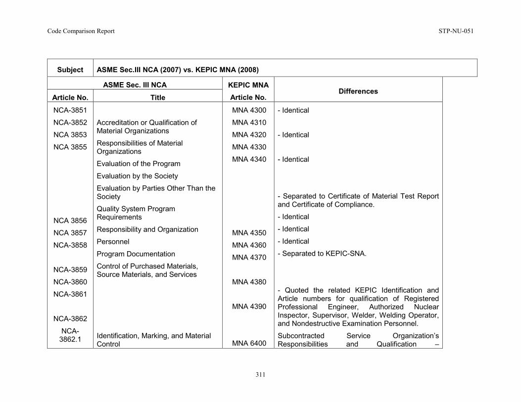
Code Comparison Report STP-NU-051
311
Subject ASME Sec.III NCA (2007) vs. KEPIC MNA (2008)
ASME Sec. III NCA KEPIC MNA Article No.
Differences Article No. Title
NCA-3851
NCA-3852
NCA 3853
NCA 3855
NCA 3856
NCA 3857
NCA-3858
NCA-3859
NCA-3860
NCA-3861
NCA-3862
NCA-3862.1
Accreditation or Qualification of Material Organizations
Responsibilities of Material Organizations
Evaluation of the Program
Evaluation by the Society
Evaluation by Parties Other Than the Society
Quality System Program Requirements
Responsibility and Organization
Personnel
Program Documentation
Control of Purchased Materials, Source Materials, and Services
Identification, Marking, and Material Control
MNA 4300
MNA 4310
MNA 4320
MNA 4330
MNA 4340
MNA 4350
MNA 4360
MNA 4370
MNA 4380
MNA 4390
MNA 6400
- Identical
- Identical
- Identical
- Separated to Certificate of Material Test Report and Certificate of Compliance.
- Identical
- Identical
- Identical
- Separated to KEPIC-SNA.
- Quoted the related KEPIC Identification and Article numbers for qualification of Registered Professional Engineer, Authorized Nuclear Inspector, Supervisor, Welder, Welding Operator, and Nondestructive Examination Personnel.
Subcontracted Service Organization’s Responsibilities and Qualification –
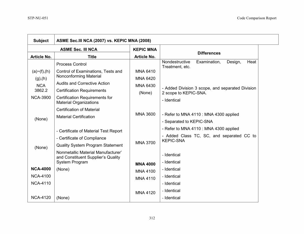
STP-NU-051 Code Comparison Report
312
Subject ASME Sec.III NCA (2007) vs. KEPIC MNA (2008)
ASME Sec. III NCA KEPIC MNA Article No.
Differences Article No. Title
(a)~(f),(h)
(g),(h)
NCA 3862.2
NCA-3900
(None)
(None)
NCA-4000 NCA-4100
NCA-4110
NCA-4120
Process Control
Control of Examinations, Tests and Nonconforming Material
Audits and Corrective Action
Certification Requirements
Certification Requirements for Material Organizations
Certification of Material
Material Certification
- Certificate of Material Test Report
- Certificate of Compliance
Quality System Program Statement
Nonmetallic Material Manufacturer’ and Constituent Supplier’s Quality System Program
(None)
(None)
MNA 6410
MNA 6420
MNA 6430
(None)
MNA 3600
MNA 3700
MNA 4000 MNA 4100
MNA 4110
MNA 4120
Nondestructive Examination, Design, Heat Treatment, etc.
- Added Division 3 scope, and separated Division 2 scope to KEPIC-SNA.
- Identical
- Refer to MNA 4110 : MNA 4300 applied
- Separated to KEPIC-SNA
- Refer to MNA 4110 : MNA 4300 applied
- Added Class TC, SC, and separated CC to KEPIC-SNA
- Identical
- Identical
- Identical
- Identical
- Identical
- Identical
- Identical
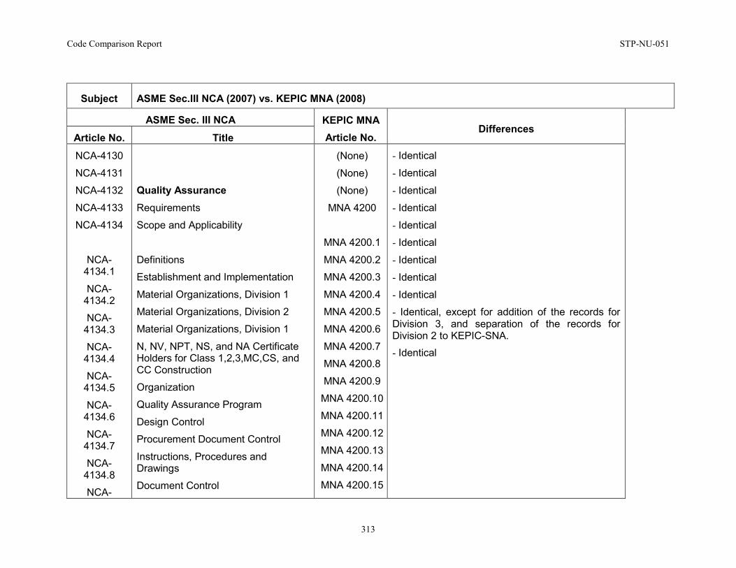
Code Comparison Report STP-NU-051
313
Subject ASME Sec.III NCA (2007) vs. KEPIC MNA (2008)
ASME Sec. III NCA KEPIC MNA Article No.
Differences Article No. Title
NCA-4130
NCA-4131
NCA-4132
NCA-4133
NCA-4134
NCA-4134.1
NCA-4134.2
NCA-4134.3
NCA-4134.4
NCA-4134.5
NCA-4134.6
NCA-4134.7
NCA-4134.8
NCA-
Quality Assurance Requirements
Scope and Applicability
Definitions
Establishment and Implementation
Material Organizations, Division 1
Material Organizations, Division 2
Material Organizations, Division 1
N, NV, NPT, NS, and NA Certificate Holders for Class 1,2,3,MC,CS, and CC Construction
Organization
Quality Assurance Program
Design Control
Procurement Document Control
Instructions, Procedures and Drawings
Document Control
(None)
(None)
(None)
MNA 4200
MNA 4200.1
MNA 4200.2
MNA 4200.3
MNA 4200.4
MNA 4200.5
MNA 4200.6
MNA 4200.7
MNA 4200.8
MNA 4200.9
MNA 4200.10
MNA 4200.11
MNA 4200.12
MNA 4200.13
MNA 4200.14
MNA 4200.15
- Identical
- Identical
- Identical
- Identical
- Identical
- Identical
- Identical
- Identical
- Identical
- Identical, except for addition of the records for Division 3, and separation of the records for Division 2 to KEPIC-SNA. - Identical
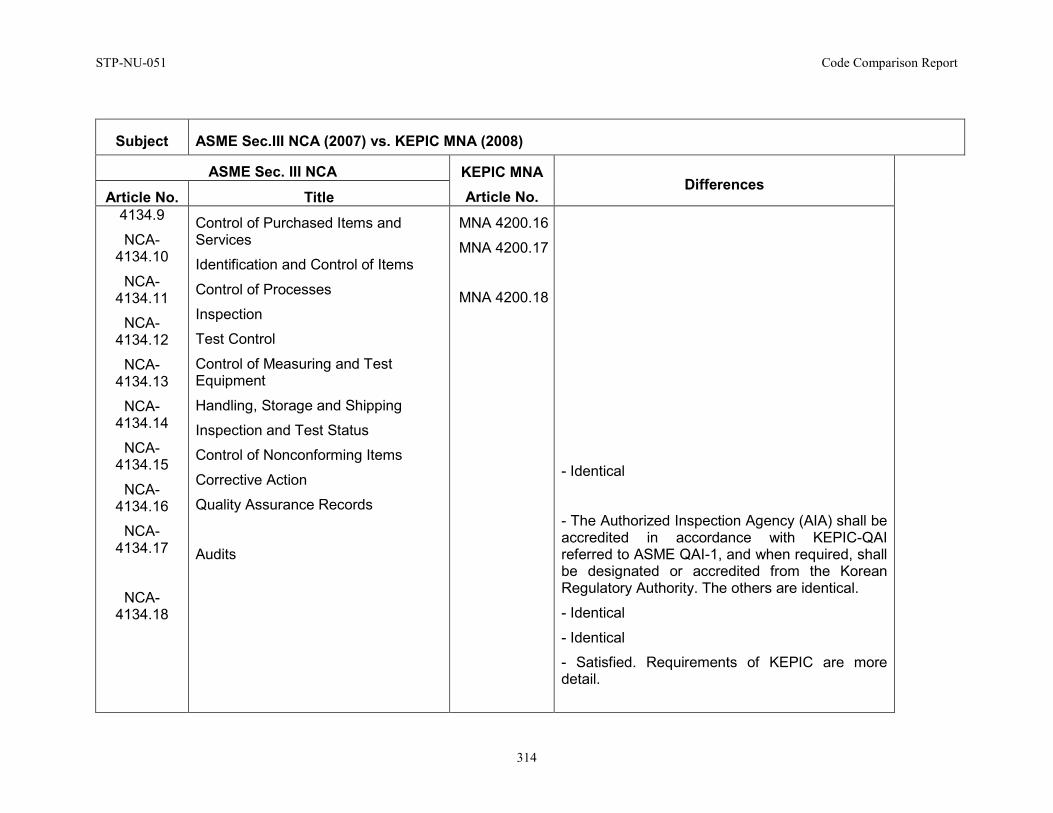
STP-NU-051 Code Comparison Report
314
Subject ASME Sec.III NCA (2007) vs. KEPIC MNA (2008)
ASME Sec. III NCA KEPIC MNA Article No.
Differences Article No. Title
4134.9
NCA-4134.10
NCA-4134.11
NCA-4134.12
NCA-4134.13
NCA-4134.14
NCA-4134.15
NCA-4134.16
NCA-4134.17
NCA-4134.18
Control of Purchased Items and Services
Identification and Control of Items
Control of Processes
Inspection
Test Control
Control of Measuring and Test Equipment
Handling, Storage and Shipping
Inspection and Test Status
Control of Nonconforming Items
Corrective Action
Quality Assurance Records
Audits
MNA 4200.16
MNA 4200.17
MNA 4200.18
- Identical
- The Authorized Inspection Agency (AIA) shall be accredited in accordance with KEPIC-QAI referred to ASME QAI-1, and when required, shall be designated or accredited from the Korean Regulatory Authority. The others are identical.
- Identical
- Identical
- Satisfied. Requirements of KEPIC are more detail.
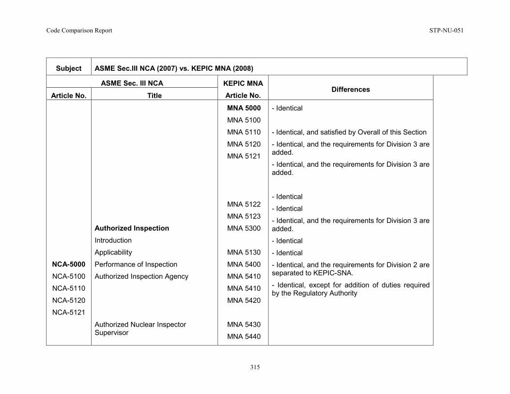
Code Comparison Report STP-NU-051
315
Subject ASME Sec.III NCA (2007) vs. KEPIC MNA (2008)
ASME Sec. III NCA KEPIC MNA Article No.
Differences Article No. Title
NCA-5000 NCA-5100
NCA-5110
NCA-5120
NCA-5121
Authorized Inspection Introduction
Applicability
Performance of Inspection
Authorized Inspection Agency
Authorized Nuclear Inspector Supervisor
MNA 5000 MNA 5100
MNA 5110
MNA 5120
MNA 5121
MNA 5122
MNA 5123
MNA 5300
MNA 5130
MNA 5400
MNA 5410
MNA 5410
MNA 5420
MNA 5430
MNA 5440
- Identical
- Identical, and satisfied by Overall of this Section
- Identical, and the requirements for Division 3 are added.
- Identical, and the requirements for Division 3 are added.
- Identical
- Identical
- Identical, and the requirements for Division 3 are added.
- Identical
- Identical
- Identical, and the requirements for Division 2 are separated to KEPIC-SNA.
- Identical, except for addition of duties required by the Regulatory Authority
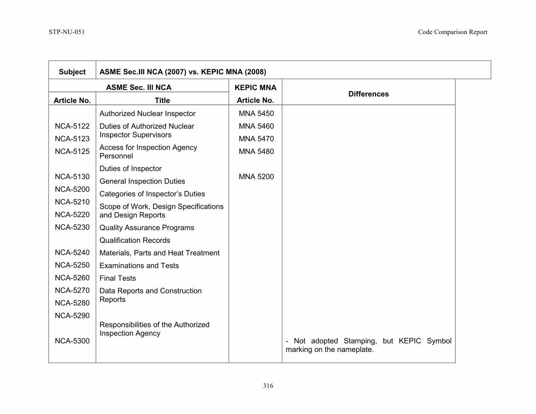
STP-NU-051 Code Comparison Report
316
Subject ASME Sec.III NCA (2007) vs. KEPIC MNA (2008)
ASME Sec. III NCA KEPIC MNA Article No.
Differences Article No. Title
NCA-5122
NCA-5123
NCA-5125
NCA-5130
NCA-5200
NCA-5210
NCA-5220
NCA-5230
NCA-5240
NCA-5250
NCA-5260
NCA-5270
NCA-5280
NCA-5290
NCA-5300
Authorized Nuclear Inspector
Duties of Authorized Nuclear Inspector Supervisors
Access for Inspection Agency Personnel
Duties of Inspector
General Inspection Duties
Categories of Inspector’s Duties
Scope of Work, Design Specifications and Design Reports
Quality Assurance Programs
Qualification Records
Materials, Parts and Heat Treatment
Examinations and Tests
Final Tests
Data Reports and Construction Reports
Responsibilities of the Authorized Inspection Agency
MNA 5450
MNA 5460
MNA 5470
MNA 5480
MNA 5200
- Not adopted Stamping, but KEPIC Symbol marking on the nameplate.
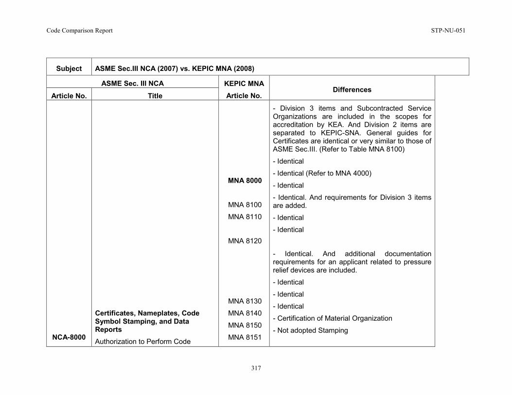
Code Comparison Report STP-NU-051
317
Subject ASME Sec.III NCA (2007) vs. KEPIC MNA (2008)
ASME Sec. III NCA KEPIC MNA Article No.
Differences Article No. Title
NCA-8000
Certificates, Nameplates, Code Symbol Stamping, and Data Reports Authorization to Perform Code
MNA 8000
MNA 8100
MNA 8110
MNA 8120
MNA 8130
MNA 8140
MNA 8150
MNA 8151
- Division 3 items and Subcontracted Service Organizations are included in the scopes for accreditation by KEA. And Division 2 items are separated to KEPIC-SNA. General guides for Certificates are identical or very similar to those of ASME Sec.III. (Refer to Table MNA 8100)
- Identical
- Identical (Refer to MNA 4000)
- Identical
- Identical. And requirements for Division 3 items are added.
- Identical
- Identical
- Identical. And additional documentation requirements for an applicant related to pressure relief devices are included.
- Identical
- Identical
- Identical
- Certification of Material Organization
- Not adopted Stamping
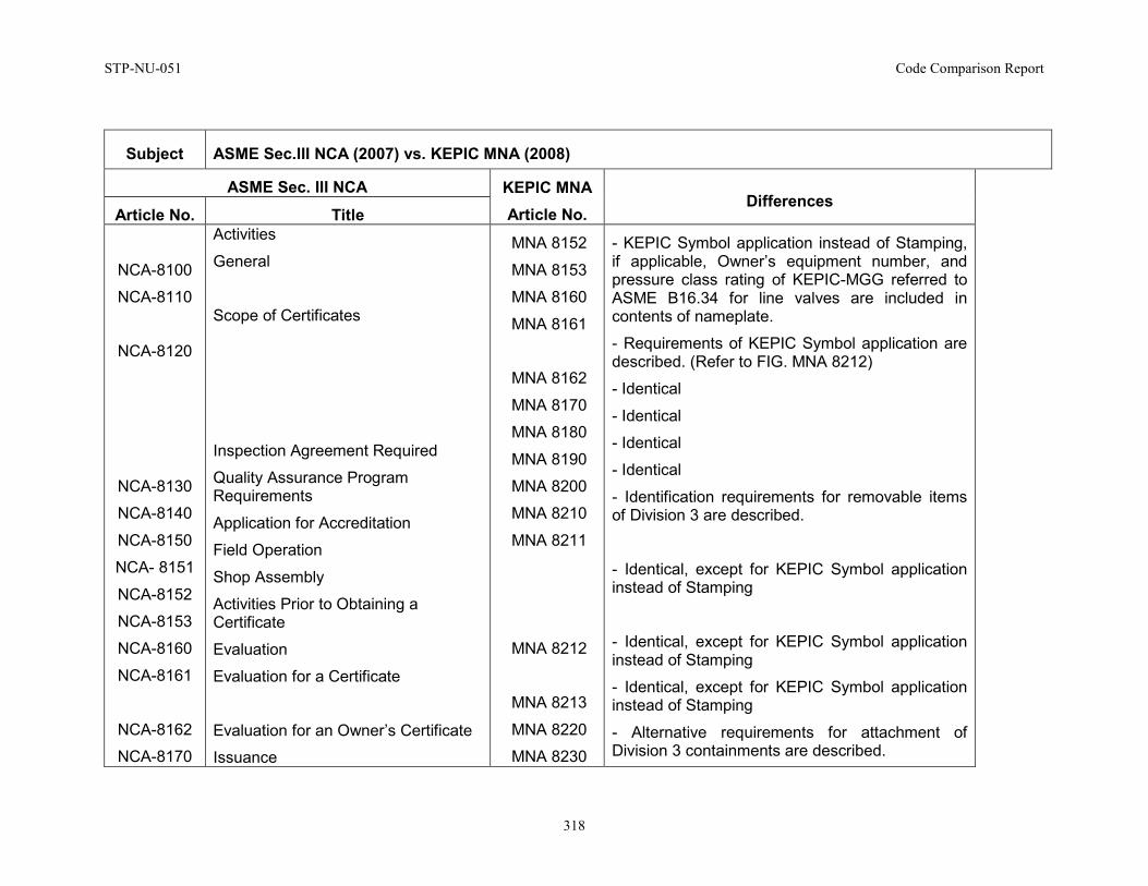
STP-NU-051 Code Comparison Report
318
Subject ASME Sec.III NCA (2007) vs. KEPIC MNA (2008)
ASME Sec. III NCA KEPIC MNA Article No.
Differences Article No. Title
NCA-8100
NCA-8110
NCA-8120
NCA-8130
NCA-8140
NCA-8150
NCA- 8151
NCA-8152
NCA-8153
NCA-8160
NCA-8161
NCA-8162
NCA-8170
Activities
General
Scope of Certificates
Inspection Agreement Required
Quality Assurance Program Requirements
Application for Accreditation
Field Operation
Shop Assembly
Activities Prior to Obtaining a Certificate
Evaluation
Evaluation for a Certificate
Evaluation for an Owner’s Certificate
Issuance
MNA 8152
MNA 8153
MNA 8160
MNA 8161
MNA 8162
MNA 8170
MNA 8180
MNA 8190
MNA 8200
MNA 8210
MNA 8211
MNA 8212
MNA 8213
MNA 8220
MNA 8230
- KEPIC Symbol application instead of Stamping, if applicable, Owner’s equipment number, and pressure class rating of KEPIC-MGG referred to ASME B16.34 for line valves are included in contents of nameplate.
- Requirements of KEPIC Symbol application are described. (Refer to FIG. MNA 8212)
- Identical
- Identical
- Identical
- Identical
- Identification requirements for removable items of Division 3 are described.
- Identical, except for KEPIC Symbol application instead of Stamping
- Identical, except for KEPIC Symbol application instead of Stamping
- Identical, except for KEPIC Symbol application instead of Stamping
- Alternative requirements for attachment of Division 3 containments are described.
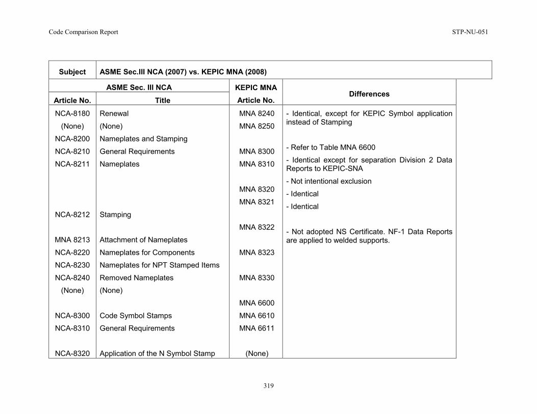
Code Comparison Report STP-NU-051
319
Subject ASME Sec.III NCA (2007) vs. KEPIC MNA (2008)
ASME Sec. III NCA KEPIC MNA Article No.
Differences Article No. Title
NCA-8180
(None)
NCA-8200
NCA-8210
NCA-8211
NCA-8212
MNA 8213
NCA-8220
NCA-8230
NCA-8240
(None)
NCA-8300
NCA-8310
NCA-8320
Renewal
(None)
Nameplates and Stamping
General Requirements
Nameplates
Stamping
Attachment of Nameplates
Nameplates for Components
Nameplates for NPT Stamped Items
Removed Nameplates
(None)
Code Symbol Stamps
General Requirements
Application of the N Symbol Stamp
MNA 8240
MNA 8250
MNA 8300
MNA 8310
MNA 8320
MNA 8321
MNA 8322
MNA 8323
MNA 8330
MNA 6600
MNA 6610
MNA 6611
(None)
- Identical, except for KEPIC Symbol application instead of Stamping
- Refer to Table MNA 6600
- Identical except for separation Division 2 Data Reports to KEPIC-SNA
- Not intentional exclusion
- Identical
- Identical
- Not adopted NS Certificate. NF-1 Data Reports are applied to welded supports.
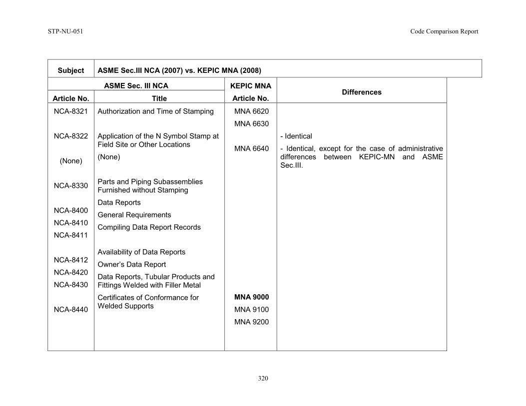
STP-NU-051 Code Comparison Report
320
Subject ASME Sec.III NCA (2007) vs. KEPIC MNA (2008)
ASME Sec. III NCA KEPIC MNA Article No.
Differences Article No. Title
NCA-8321
NCA-8322
(None)
NCA-8330
NCA-8400
NCA-8410
NCA-8411
NCA-8412
NCA-8420
NCA-8430
NCA-8440
Authorization and Time of Stamping
Application of the N Symbol Stamp at Field Site or Other Locations
(None)
Parts and Piping Subassemblies Furnished without Stamping
Data Reports
General Requirements
Compiling Data Report Records
Availability of Data Reports
Owner’s Data Report
Data Reports, Tubular Products and Fittings Welded with Filler Metal
Certificates of Conformance for Welded Supports
MNA 6620
MNA 6630
MNA 6640
MNA 9000 MNA 9100
MNA 9200
- Identical
- Identical, except for the case of administrative differences between KEPIC-MN and ASME Sec.III.
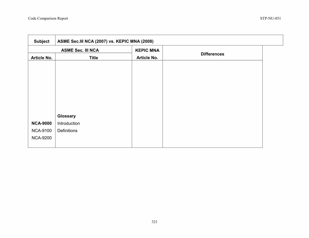
Code Comparison Report STP-NU-051
321
Subject ASME Sec.III NCA (2007) vs. KEPIC MNA (2008)
ASME Sec. III NCA KEPIC MNA Article No.
Differences Article No. Title
NCA-9000 NCA-9100
NCA-9200
Glossary Introduction
Definitions
STP-NU-051 Code Comparison Report
322
APPENDIX D: CSA N285 VERSUS ASME SECTION III DETAILED COMPARISON TABLE
Appendix D1: CSA N285.0 Versus ASME Section III Div. 1 – NB Comparison Appendix D2 : CSA N285.0 Versus ASME SECTION III DIV. 1 - NCA COMPARISON
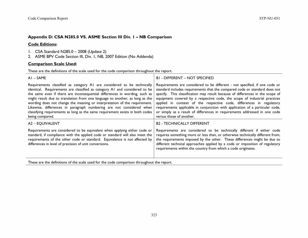
Code Comparison Report STP-NU-051
323
Appendix D: CSA N285.0 VS. ASME Section III Div. 1 – NB Comparison
Code Editions:
1. CSA Standard N285.0 – 2008 (Update 2) 2. ASME BPV Code Section III, Div. 1, NB, 2007 Edition (No Addenda)
Comparison Scale Used:
These are the definitions of the scale used for the code comparison throughout the report.
A1 – SAME
Requirements classified as category A1 are considered to be technically identical. Requirements are classified as category A1 and considered to be the same even if there are inconsequential differences in wording, such as might result due to translation from one language to another, as long as the wording does not change the meaning or interpretation of the requirement. Likewise, differences in paragraph numbering are not considered when classifying requirements as long as the same requirement exists in both codes being compared.
B1 - DIFFERENT – NOT SPECIFIED
Requirements are considered to be different - not specified, if one code or standard includes requirements that the compared code or standard does not specify. This classification may result because of differences in the scope of equipment covered by a respective code, the scope of industrial practices applied in context of the respective code, differences in regulatory requirements applicable in conjunction with application of a particular code, or simply as a result of differences in requirements addressed in one code versus those of another.
A2 – EQUIVALENT
Requirements are considered to be equivalent when applying either code or standard, if compliance with the applied code or standard will also meet the requirements of the other code or standard. Equivalence is not affected by differences in level of precision of unit conversions.
B2 - TECHNICALLY DIFFERENT
Requirements are considered to be technically different if either code requires something more or less than, or otherwise technically different from, the requirements imposed by the other. These differences might be due to different technical approaches applied by a code or imposition of regulatory requirements within the country from which a code originates.
These are the definitions of the scale used for the code comparison throughout the report.
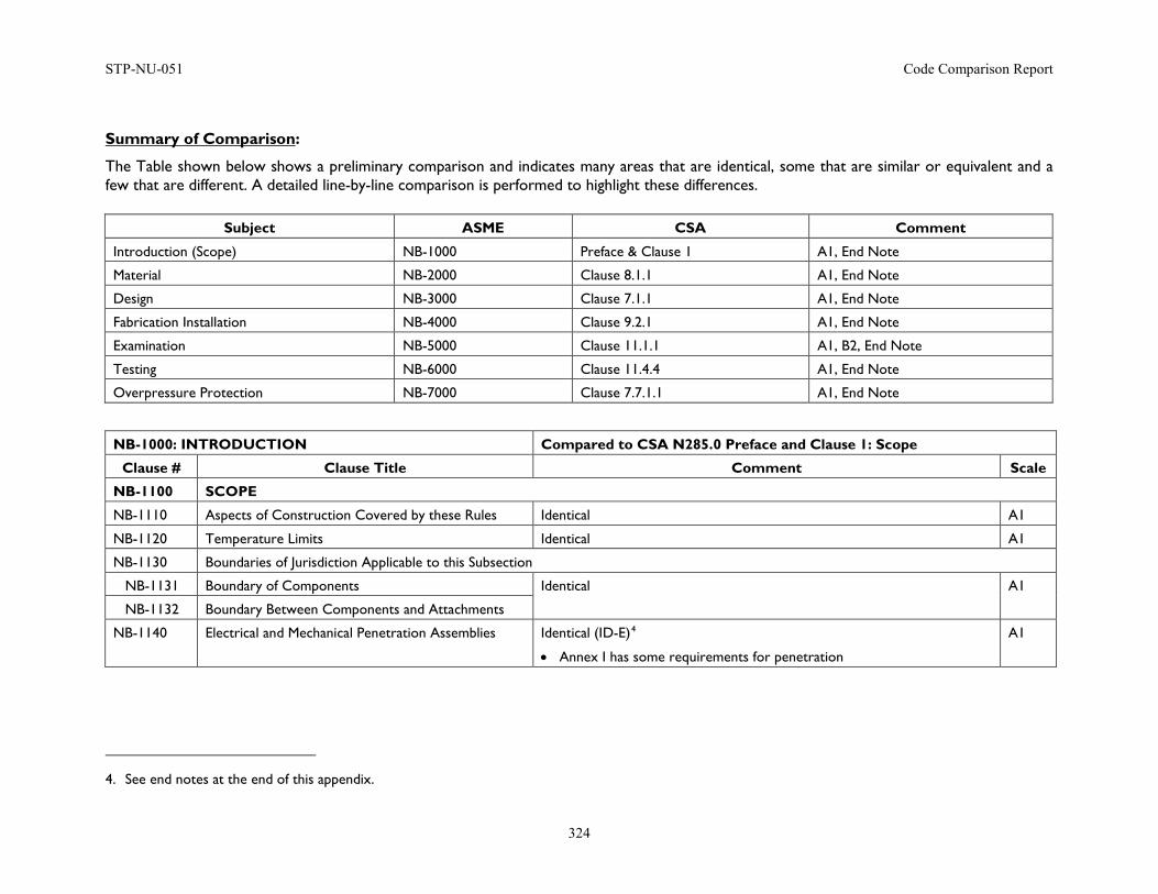
STP-NU-051 Code Comparison Report
324
Summary of Comparison:
The Table shown below shows a preliminary comparison and indicates many areas that are identical, some that are similar or equivalent and a few that are different. A detailed line-by-line comparison is performed to highlight these differences.
Subject ASME CSA Comment
Introduction (Scope) NB-1000 Preface & Clause 1 A1, End Note
Material NB-2000 Clause 8.1.1 A1, End Note
Design NB-3000 Clause 7.1.1 A1, End Note
Fabrication Installation NB-4000 Clause 9.2.1 A1, End Note
Examination NB-5000 Clause 11.1.1 A1, B2, End Note
Testing NB-6000 Clause 11.4.4 A1, End Note
Overpressure Protection NB-7000 Clause 7.7.1.1 A1, End Note
NB-1000: INTRODUCTION Compared to CSA N285.0 Preface and Clause 1: Scope
Clause # Clause Title Comment Scale
NB-1100 SCOPE
NB-1110 Aspects of Construction Covered by these Rules Identical A1
NB-1120 Temperature Limits Identical A1
NB-1130 Boundaries of Jurisdiction Applicable to this Subsection
NB-1131 Boundary of Components Identical A1
NB-1132 Boundary Between Components and Attachments
NB-1140 Electrical and Mechanical Penetration Assemblies Identical (ID-E)4
• Annex I has some requirements for penetration
A1
4. See end notes at the end of this appendix.
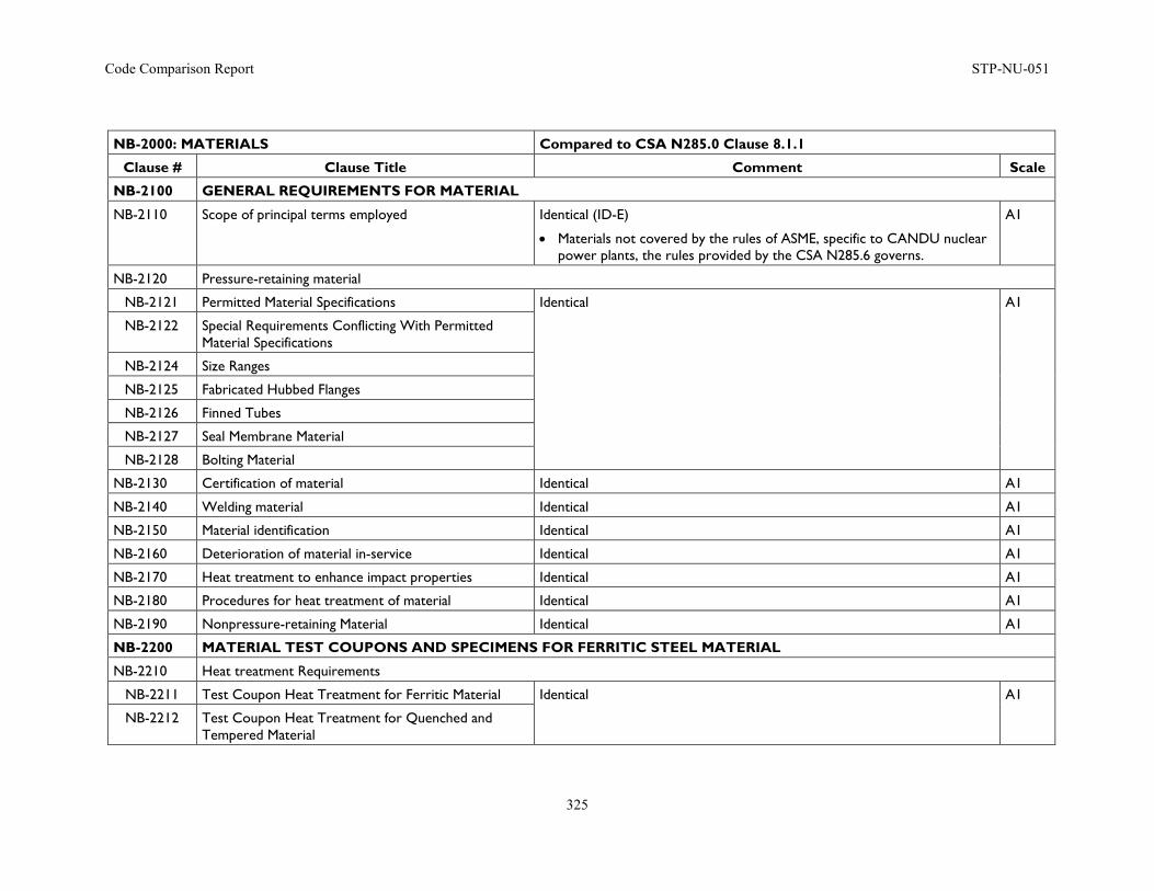
Code Comparison Report STP-NU-051
325
NB-2000: MATERIALS Compared to CSA N285.0 Clause 8.1.1
Clause # Clause Title Comment Scale
NB-2100 GENERAL REQUIREMENTS FOR MATERIAL
NB-2110 Scope of principal terms employed Identical (ID-E)
• Materials not covered by the rules of ASME, specific to CANDU nuclear power plants, the rules provided by the CSA N285.6 governs.
A1
NB-2120 Pressure-retaining material
NB-2121 Permitted Material Specifications Identical A1
NB-2122 Special Requirements Conflicting With Permitted Material Specifications
NB-2124 Size Ranges
NB-2125 Fabricated Hubbed Flanges
NB-2126 Finned Tubes
NB-2127 Seal Membrane Material
NB-2128 Bolting Material
NB-2130 Certification of material Identical A1
NB-2140 Welding material Identical A1
NB-2150 Material identification Identical A1
NB-2160 Deterioration of material in-service Identical A1
NB-2170 Heat treatment to enhance impact properties Identical A1
NB-2180 Procedures for heat treatment of material Identical A1
NB-2190 Nonpressure-retaining Material Identical A1
NB-2200 MATERIAL TEST COUPONS AND SPECIMENS FOR FERRITIC STEEL MATERIAL
NB-2210 Heat treatment Requirements
NB-2211 Test Coupon Heat Treatment for Ferritic Material Identical A1
NB-2212 Test Coupon Heat Treatment for Quenched and Tempered Material
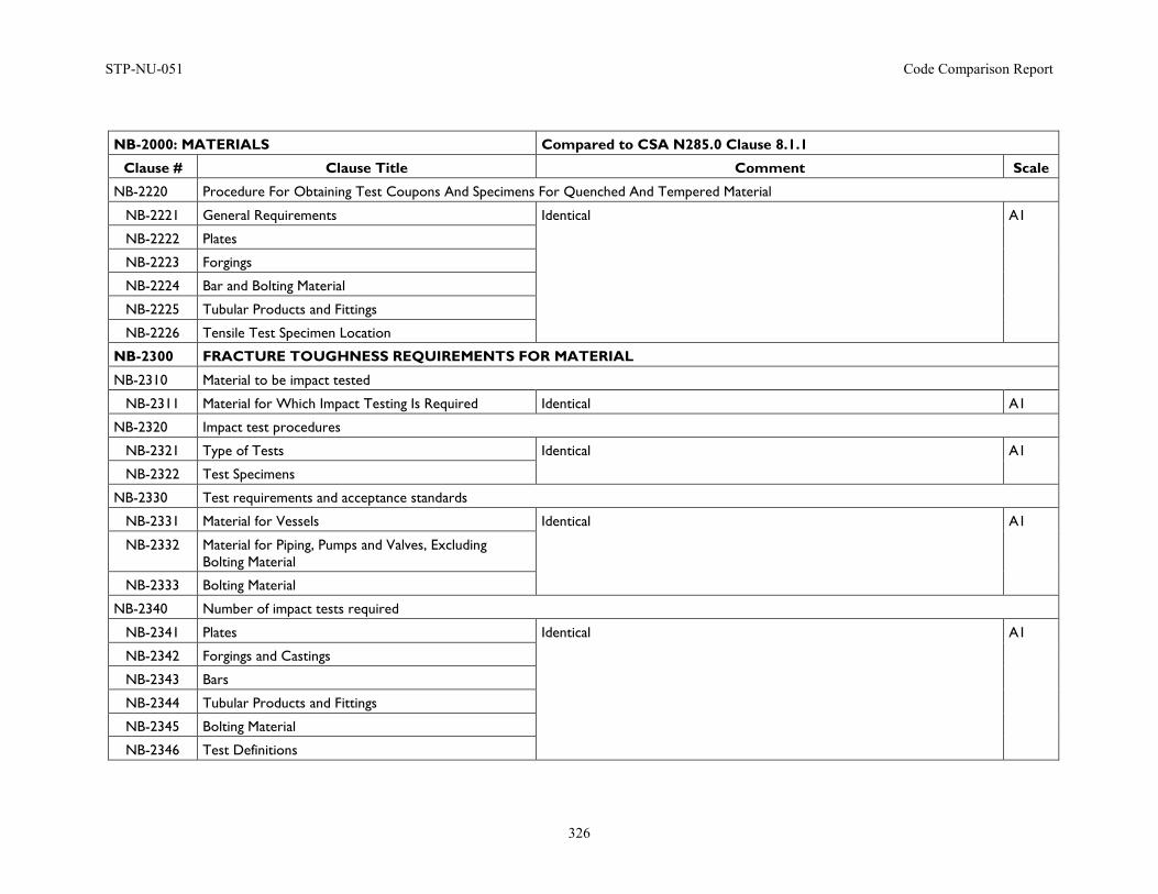
STP-NU-051 Code Comparison Report
326
NB-2000: MATERIALS Compared to CSA N285.0 Clause 8.1.1
Clause # Clause Title Comment Scale
NB-2220 Procedure For Obtaining Test Coupons And Specimens For Quenched And Tempered Material
NB-2221 General Requirements Identical A1
NB-2222 Plates
NB-2223 Forgings
NB-2224 Bar and Bolting Material
NB-2225 Tubular Products and Fittings
NB-2226 Tensile Test Specimen Location
NB-2300 FRACTURE TOUGHNESS REQUIREMENTS FOR MATERIAL
NB-2310 Material to be impact tested
NB-2311 Material for Which Impact Testing Is Required Identical A1
NB-2320 Impact test procedures
NB-2321 Type of Tests Identical A1
NB-2322 Test Specimens
NB-2330 Test requirements and acceptance standards
NB-2331 Material for Vessels Identical A1
NB-2332 Material for Piping, Pumps and Valves, Excluding Bolting Material
NB-2333 Bolting Material
NB-2340 Number of impact tests required
NB-2341 Plates Identical A1
NB-2342 Forgings and Castings
NB-2343 Bars
NB-2344 Tubular Products and Fittings
NB-2345 Bolting Material
NB-2346 Test Definitions
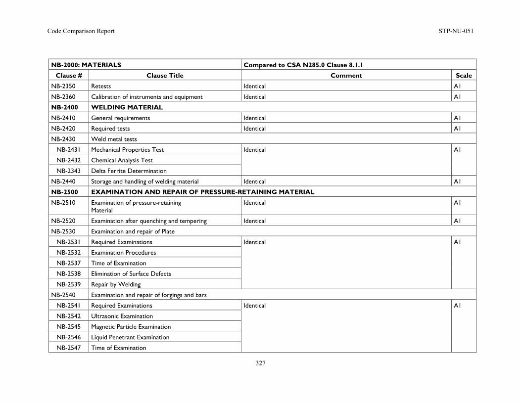
Code Comparison Report STP-NU-051
327
NB-2000: MATERIALS Compared to CSA N285.0 Clause 8.1.1
Clause # Clause Title Comment Scale
NB-2350 Retests Identical A1
NB-2360 Calibration of instruments and equipment Identical A1
NB-2400 WELDING MATERIAL
NB-2410 General requirements Identical A1
NB-2420 Required tests Identical A1
NB-2430 Weld metal tests
NB-2431 Mechanical Properties Test Identical A1
NB-2432 Chemical Analysis Test
NB-2343 Delta Ferrite Determination
NB-2440 Storage and handling of welding material Identical A1
NB-2500 EXAMINATION AND REPAIR OF PRESSURE-RETAINING MATERIAL
NB-2510 Examination of pressure-retaining Material
Identical A1
NB-2520 Examination after quenching and tempering Identical A1
NB-2530 Examination and repair of Plate
NB-2531 Required Examinations Identical A1
NB-2532 Examination Procedures
NB-2537 Time of Examination
NB-2538 Elimination of Surface Defects
NB-2539 Repair by Welding
NB-2540 Examination and repair of forgings and bars
NB-2541 Required Examinations Identical A1
NB-2542 Ultrasonic Examination
NB-2545 Magnetic Particle Examination
NB-2546 Liquid Penetrant Examination
NB-2547 Time of Examination
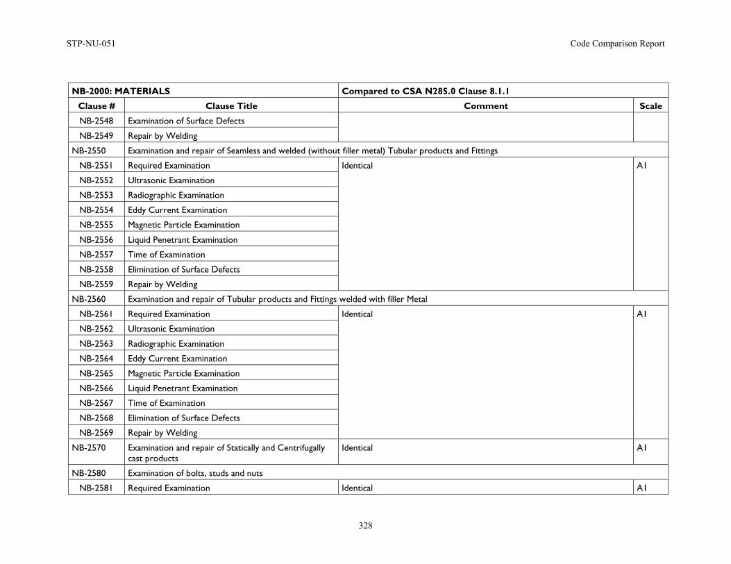
STP-NU-051 Code Comparison Report
328
NB-2000: MATERIALS Compared to CSA N285.0 Clause 8.1.1
Clause # Clause Title Comment Scale
NB-2548 Examination of Surface Defects
NB-2549 Repair by Welding
NB-2550 Examination and repair of Seamless and welded (without filler metal) Tubular products and Fittings
NB-2551 Required Examination Identical A1
NB-2552 Ultrasonic Examination
NB-2553 Radiographic Examination
NB-2554 Eddy Current Examination
NB-2555 Magnetic Particle Examination
NB-2556 Liquid Penetrant Examination
NB-2557 Time of Examination
NB-2558 Elimination of Surface Defects
NB-2559 Repair by Welding
NB-2560 Examination and repair of Tubular products and Fittings welded with filler Metal
NB-2561 Required Examination Identical A1
NB-2562 Ultrasonic Examination
NB-2563 Radiographic Examination
NB-2564 Eddy Current Examination
NB-2565 Magnetic Particle Examination
NB-2566 Liquid Penetrant Examination
NB-2567 Time of Examination
NB-2568 Elimination of Surface Defects
NB-2569 Repair by Welding
NB-2570 Examination and repair of Statically and Centrifugally cast products
Identical A1
NB-2580 Examination of bolts, studs and nuts
NB-2581 Required Examination Identical A1
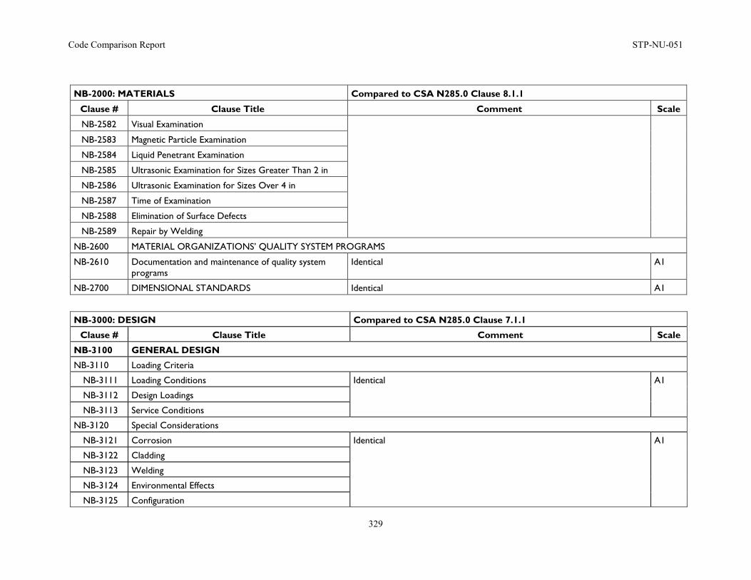
Code Comparison Report STP-NU-051
329
NB-2000: MATERIALS Compared to CSA N285.0 Clause 8.1.1
Clause # Clause Title Comment Scale
NB-2582 Visual Examination
NB-2583 Magnetic Particle Examination
NB-2584 Liquid Penetrant Examination
NB-2585 Ultrasonic Examination for Sizes Greater Than 2 in
NB-2586 Ultrasonic Examination for Sizes Over 4 in
NB-2587 Time of Examination
NB-2588 Elimination of Surface Defects
NB-2589 Repair by Welding
NB-2600 MATERIAL ORGANIZATIONS’ QUALITY SYSTEM PROGRAMS
NB-2610 Documentation and maintenance of quality system programs
Identical A1
NB-2700 DIMENSIONAL STANDARDS Identical A1
NB-3000: DESIGN Compared to CSA N285.0 Clause 7.1.1
Clause # Clause Title Comment Scale
NB-3100 GENERAL DESIGN
NB-3110 Loading Criteria
NB-3111 Loading Conditions Identical A1
NB-3112 Design Loadings
NB-3113 Service Conditions
NB-3120 Special Considerations
NB-3121 Corrosion Identical A1
NB-3122 Cladding
NB-3123 Welding
NB-3124 Environmental Effects
NB-3125 Configuration
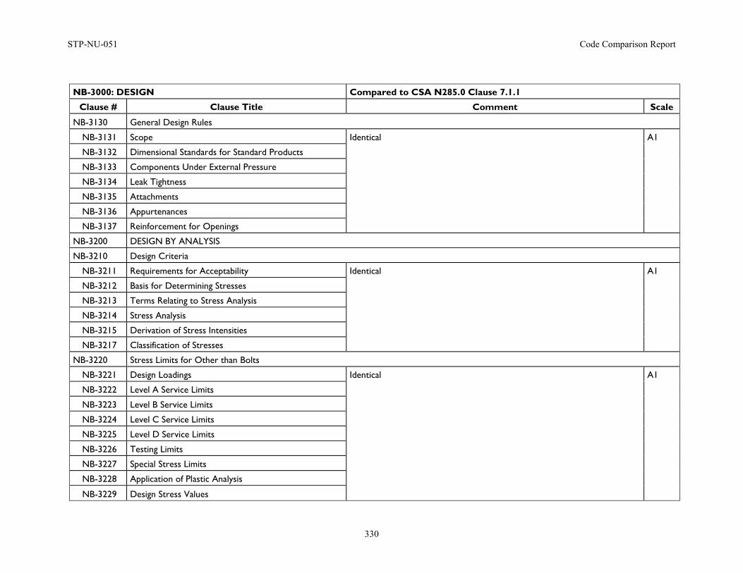
STP-NU-051 Code Comparison Report
330
NB-3000: DESIGN Compared to CSA N285.0 Clause 7.1.1
Clause # Clause Title Comment Scale
NB-3130 General Design Rules
NB-3131 Scope Identical A1
NB-3132 Dimensional Standards for Standard Products
NB-3133 Components Under External Pressure
NB-3134 Leak Tightness
NB-3135 Attachments
NB-3136 Appurtenances
NB-3137 Reinforcement for Openings
NB-3200 DESIGN BY ANALYSIS
NB-3210 Design Criteria
NB-3211 Requirements for Acceptability Identical A1
NB-3212 Basis for Determining Stresses
NB-3213 Terms Relating to Stress Analysis
NB-3214 Stress Analysis
NB-3215 Derivation of Stress Intensities
NB-3217 Classification of Stresses
NB-3220 Stress Limits for Other than Bolts
NB-3221 Design Loadings Identical A1
NB-3222 Level A Service Limits
NB-3223 Level B Service Limits
NB-3224 Level C Service Limits
NB-3225 Level D Service Limits
NB-3226 Testing Limits
NB-3227 Special Stress Limits
NB-3228 Application of Plastic Analysis
NB-3229 Design Stress Values
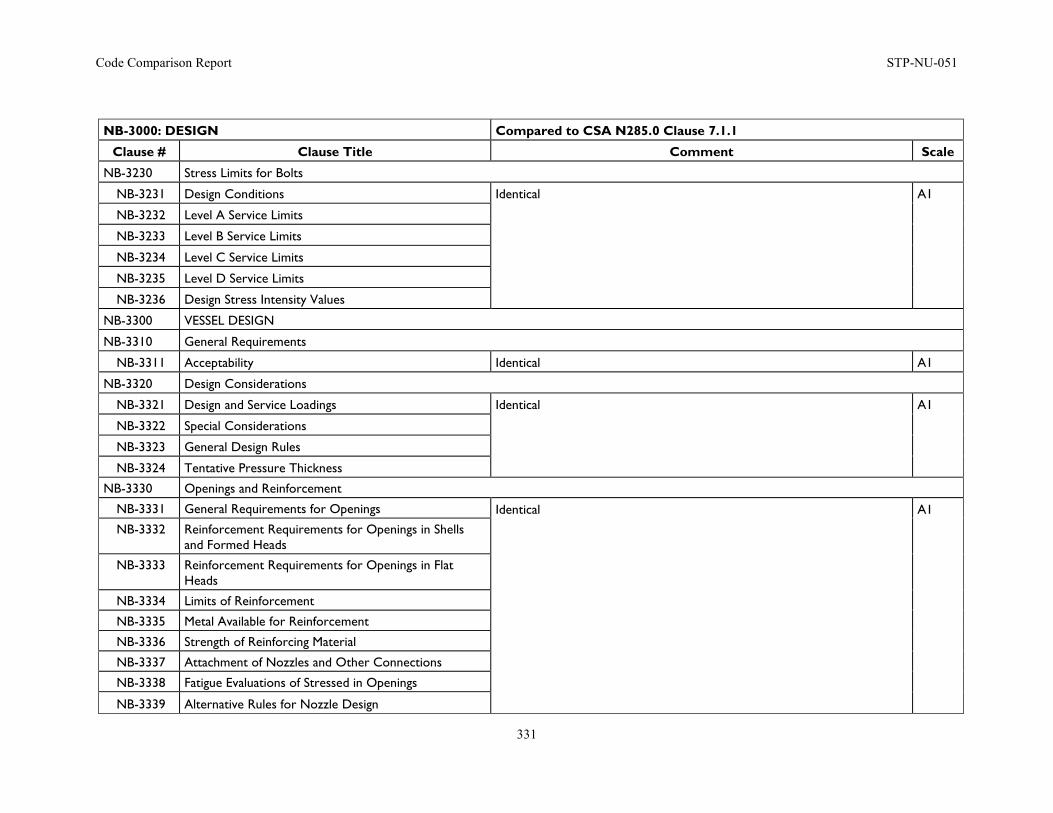
Code Comparison Report STP-NU-051
331
NB-3000: DESIGN Compared to CSA N285.0 Clause 7.1.1
Clause # Clause Title Comment Scale
NB-3230 Stress Limits for Bolts
NB-3231 Design Conditions Identical A1
NB-3232 Level A Service Limits
NB-3233 Level B Service Limits
NB-3234 Level C Service Limits
NB-3235 Level D Service Limits
NB-3236 Design Stress Intensity Values
NB-3300 VESSEL DESIGN
NB-3310 General Requirements
NB-3311 Acceptability Identical A1
NB-3320 Design Considerations
NB-3321 Design and Service Loadings Identical A1
NB-3322 Special Considerations
NB-3323 General Design Rules
NB-3324 Tentative Pressure Thickness
NB-3330 Openings and Reinforcement
NB-3331 General Requirements for Openings Identical A1 NB-3332 Reinforcement Requirements for Openings in Shells
and Formed Heads
NB-3333 Reinforcement Requirements for Openings in Flat Heads
NB-3334 Limits of Reinforcement
NB-3335 Metal Available for Reinforcement
NB-3336 Strength of Reinforcing Material
NB-3337 Attachment of Nozzles and Other Connections
NB-3338 Fatigue Evaluations of Stressed in Openings
NB-3339 Alternative Rules for Nozzle Design
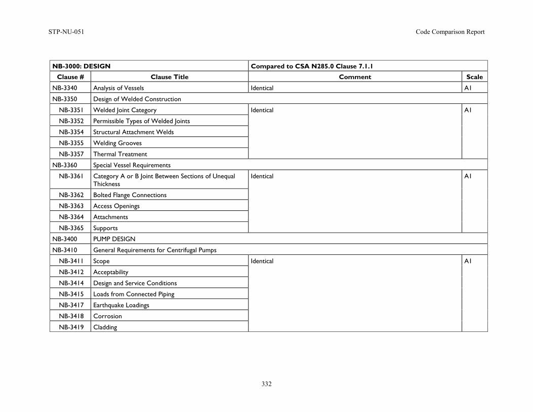
STP-NU-051 Code Comparison Report
332
NB-3000: DESIGN Compared to CSA N285.0 Clause 7.1.1
Clause # Clause Title Comment Scale
NB-3340 Analysis of Vessels Identical A1
NB-3350 Design of Welded Construction
NB-3351 Welded Joint Category Identical A1
NB-3352 Permissible Types of Welded Joints
NB-3354 Structural Attachment Welds
NB-3355 Welding Grooves
NB-3357 Thermal Treatment
NB-3360 Special Vessel Requirements
NB-3361 Category A or B Joint Between Sections of Unequal Thickness
Identical A1
NB-3362 Bolted Flange Connections
NB-3363 Access Openings
NB-3364 Attachments
NB-3365 Supports
NB-3400 PUMP DESIGN
NB-3410 General Requirements for Centrifugal Pumps
NB-3411 Scope Identical A1
NB-3412 Acceptability
NB-3414 Design and Service Conditions
NB-3415 Loads from Connected Piping
NB-3417 Earthquake Loadings
NB-3418 Corrosion
NB-3419 Cladding
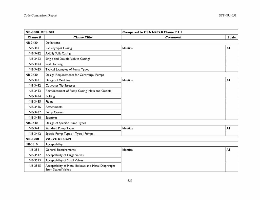
Code Comparison Report STP-NU-051
333
NB-3000: DESIGN Compared to CSA N285.0 Clause 7.1.1
Clause # Clause Title Comment Scale
NB-3420 Definitions
NB-3421 Radially Split Casing Identical A1
NB-3422 Axially Split Casing
NB-3423 Single and Double Volute Casings
NB-3424 Seal Housing
NB-3425 Typical Examples of Pump Types
NB-3430 Design Requirements for Centrifugal Pumps
NB-3431 Design of Welding Identical A1
NB-3432 Cutwater Tip Stresses
NB-3433 Reinforcement of Pump Casing Inlets and Outlets
NB-3434 Bolting
NB-3435 Piping
NB-3436 Attachments
NB-3437 Pump Covers
NB-3438 Supports
NB-3440 Design of Specific Pump Types
NB-3441 Standard Pump Types Identical A1
NB-3442 Special Pump Types – Type J Pumps
NB-3500 VALVE DESIGN
NB-3510 Acceptability
NB-3511 General Requirements Identical A1
NB-3512 Acceptability of Large Valves
NB-3513 Acceptability of Small Valves
NB-3515 Acceptability of Metal Bellows and Metal Diaphragm Stem Sealed Valves
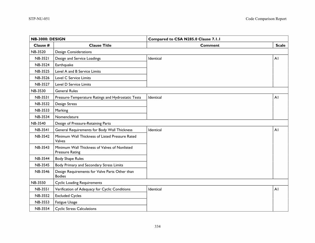
STP-NU-051 Code Comparison Report
334
NB-3000: DESIGN Compared to CSA N285.0 Clause 7.1.1
Clause # Clause Title Comment Scale
NB-3520 Design Considerations
NB-3521 Design and Service Loadings Identical A1
NB-3524 Earthquake
NB-3525 Level A and B Service Limits
NB-3526 Level C Service Limits
NB-3527 Level D Service Limits
NB-3530 General Rules
NB-3531 Pressure-Temperature Ratings and Hydrostatic Tests Identical A1
NB-3532 Design Stress
NB-3533 Marking
NB-3534 Nomenclature
NB-3540 Design of Pressure-Retaining Parts
NB-3541 General Requirements for Body Wall Thickness Identical A1
NB-3542 Minimum Wall Thickness of Listed Pressure Rated Valves
NB-3543 Minimum Wall Thickness of Valves of Nonlisted Pressure Rating
NB-3544 Body Shape Rules
NB-3545 Body Primary and Secondary Stress Limits
NB-3546 Design Requirements for Valve Parts Other than Bodies
NB-3550 Cyclic Loading Requirements
NB-3551 Verification of Adequacy for Cyclic Conditions Identical A1
NB-3552 Excluded Cycles
NB-3553 Fatigue Usage
NB-3554 Cyclic Stress Calculations
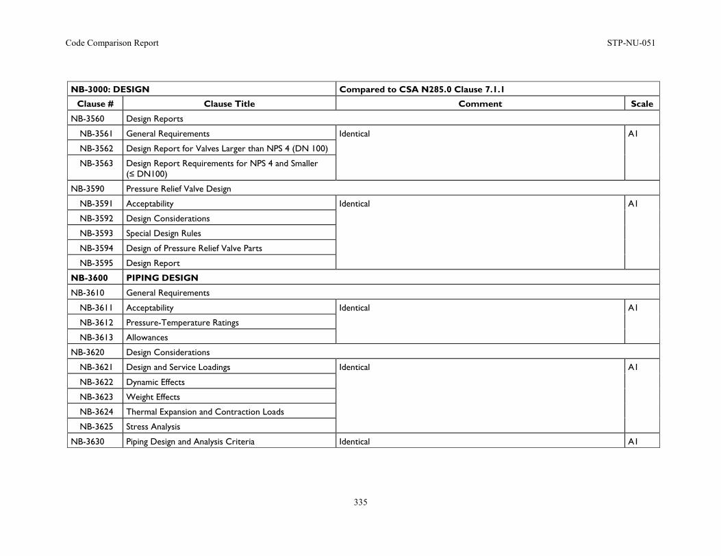
Code Comparison Report STP-NU-051
335
NB-3000: DESIGN Compared to CSA N285.0 Clause 7.1.1
Clause # Clause Title Comment Scale
NB-3560 Design Reports
NB-3561 General Requirements Identical A1
NB-3562 Design Report for Valves Larger than NPS 4 (DN 100)
NB-3563 Design Report Requirements for NPS 4 and Smaller (≤ DN100)
NB-3590 Pressure Relief Valve Design
NB-3591 Acceptability Identical A1
NB-3592 Design Considerations
NB-3593 Special Design Rules
NB-3594 Design of Pressure Relief Valve Parts
NB-3595 Design Report
NB-3600 PIPING DESIGN
NB-3610 General Requirements
NB-3611 Acceptability Identical A1
NB-3612 Pressure-Temperature Ratings
NB-3613 Allowances
NB-3620 Design Considerations
NB-3621 Design and Service Loadings Identical A1
NB-3622 Dynamic Effects
NB-3623 Weight Effects
NB-3624 Thermal Expansion and Contraction Loads
NB-3625 Stress Analysis
NB-3630 Piping Design and Analysis Criteria Identical A1
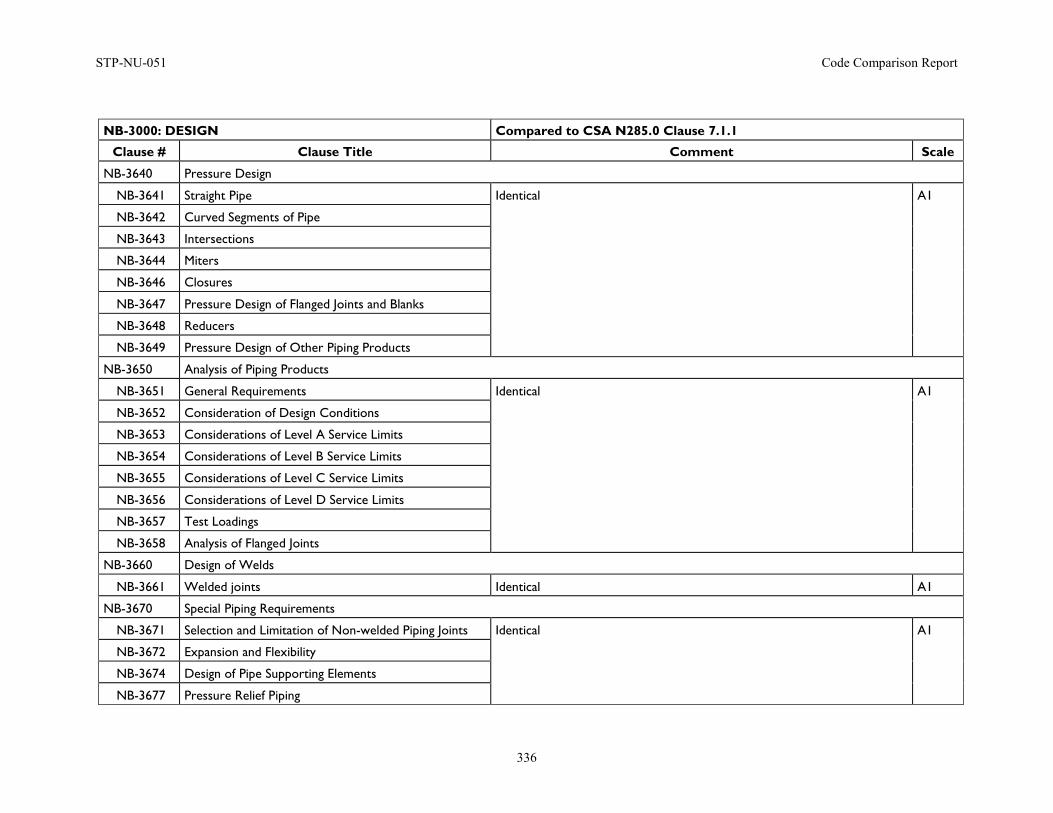
STP-NU-051 Code Comparison Report
336
NB-3000: DESIGN Compared to CSA N285.0 Clause 7.1.1
Clause # Clause Title Comment Scale
NB-3640 Pressure Design
NB-3641 Straight Pipe Identical A1
NB-3642 Curved Segments of Pipe
NB-3643 Intersections
NB-3644 Miters
NB-3646 Closures
NB-3647 Pressure Design of Flanged Joints and Blanks
NB-3648 Reducers
NB-3649 Pressure Design of Other Piping Products
NB-3650 Analysis of Piping Products
NB-3651 General Requirements Identical A1
NB-3652 Consideration of Design Conditions
NB-3653 Considerations of Level A Service Limits
NB-3654 Considerations of Level B Service Limits
NB-3655 Considerations of Level C Service Limits
NB-3656 Considerations of Level D Service Limits
NB-3657 Test Loadings
NB-3658 Analysis of Flanged Joints
NB-3660 Design of Welds
NB-3661 Welded joints Identical A1
NB-3670 Special Piping Requirements
NB-3671 Selection and Limitation of Non-welded Piping Joints Identical A1
NB-3672 Expansion and Flexibility
NB-3674 Design of Pipe Supporting Elements
NB-3677 Pressure Relief Piping
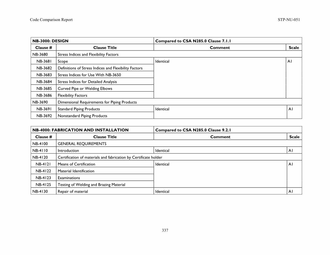
Code Comparison Report STP-NU-051
337
NB-3000: DESIGN Compared to CSA N285.0 Clause 7.1.1
Clause # Clause Title Comment Scale
NB-3680 Stress Indices and Flexibility Factors
NB-3681 Scope Identical A1
NB-3682 Definitions of Stress Indices and Flexibility Factors
NB-3683 Stress Indices for Use With NB-3650
NB-3684 Stress Indices for Detailed Analysis
NB-3685 Curved Pipe or Welding Elbows
NB-3686 Flexibility Factors
NB-3690 Dimensional Requirements for Piping Products
NB-3691 Standard Piping Products Identical A1
NB-3692 Nonstandard Piping Products
NB-4000: FABRICATION AND INSTALLATION Compared to CSA N285.0 Clause 9.2.1
Clause # Clause Title Comment Scale
NB-4100 GENERAL REQUIREMENTS
NB-4110 Introduction Identical A1
NB-4120 Certification of materials and fabrication by Certificate holder
NB-4121 Means of Certification Identical A1
NB-4122 Material Identification
NB-4123 Examinations
NB-4125 Testing of Welding and Brazing Material
NB-4130 Repair of material Identical A1
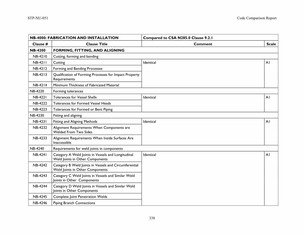
STP-NU-051 Code Comparison Report
338
NB-4000: FABRICATION AND INSTALLATION Compared to CSA N285.0 Clause 9.2.1
Clause # Clause Title Comment Scale
NB-4200 FORMING, FITTING, AND ALIGNING
NB-4210 Cutting, forming and bending
NB-4211 Cutting Identical A1
NB-4212 Forming and Bending Processes
NB-4213 Qualification of Forming Processes for Impact Property Requirements
NB-4214 Minimum Thickness of Fabricated Material
NB-4220 Forming tolerances
NB-4221 Tolerances for Vessel Shells Identical A1
NB-4222 Tolerances for Formed Vessel Heads
NB-4223 Tolerances for Formed or Bent Piping
NB-4230 Fitting and aligning
NB-4231 Fitting and Aligning Methods Identical A1
NB-4232 Alignment Requirements When Components are Welded From Two Sides
NB-4233 Alignment Requirements When Inside Surfaces Are Inaccessible
NB-4240 Requirements for weld joints in components
NB-4241 Category A Weld Joints in Vessels and Longitudinal Weld Joints in Other Components
Identical A1
NB-4242 Category B Weld Joints in Vessels and Circumferential Weld Joints in Other Components
NB-4243 Category C Weld Joints in Vessels and Similar Weld Joints in Other Components
NB-4244 Category D Weld Joints in Vessels and Similar Weld Joints in Other Components
NB-4245 Complete Joint Penetration Welds
NB-4246 Piping Branch Connections
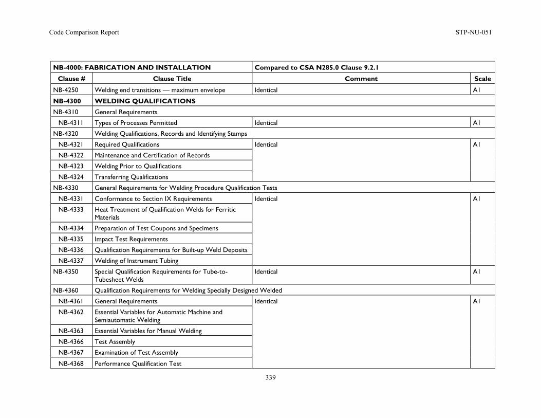
Code Comparison Report STP-NU-051
339
NB-4000: FABRICATION AND INSTALLATION Compared to CSA N285.0 Clause 9.2.1
Clause # Clause Title Comment Scale
NB-4250 Welding end transitions — maximum envelope Identical A1
NB-4300 WELDING QUALIFICATIONS
NB-4310 General Requirements
NB-4311 Types of Processes Permitted Identical A1
NB-4320 Welding Qualifications, Records and Identifying Stamps
NB-4321 Required Qualifications Identical A1
NB-4322 Maintenance and Certification of Records
NB-4323 Welding Prior to Qualifications
NB-4324 Transferring Qualifications
NB-4330 General Requirements for Welding Procedure Qualification Tests
NB-4331 Conformance to Section IX Requirements Identical A1
NB-4333 Heat Treatment of Qualification Welds for Ferritic Materials
NB-4334 Preparation of Test Coupons and Specimens
NB-4335 Impact Test Requirements
NB-4336 Qualification Requirements for Built-up Weld Deposits
NB-4337 Welding of Instrument Tubing
NB-4350 Special Qualification Requirements for Tube-to-Tubesheet Welds
Identical A1
NB-4360 Qualification Requirements for Welding Specially Designed Welded
NB-4361 General Requirements Identical A1
NB-4362 Essential Variables for Automatic Machine and Semiautomatic Welding
NB-4363 Essential Variables for Manual Welding
NB-4366 Test Assembly
NB-4367 Examination of Test Assembly
NB-4368 Performance Qualification Test
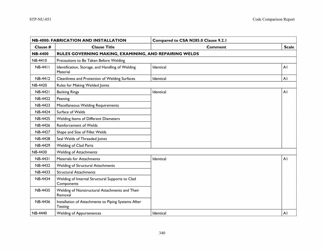
STP-NU-051 Code Comparison Report
340
NB-4000: FABRICATION AND INSTALLATION Compared to CSA N285.0 Clause 9.2.1
Clause # Clause Title Comment Scale
NB-4400 RULES GOVERNING MAKING, EXAMINING, AND REPAIRING WELDS
NB-4410 Precautions to Be Taken Before Welding
NB-4411 Identification, Storage, and Handling of Welding Material
Identical A1
NB-4412 Cleanliness and Protection of Welding Surfaces Identical A1
NB-4420 Rules for Making Welded Joints
NB-4421 Backing Rings Identical A1
NB-4422 Peening
NB-4423 Miscellaneous Welding Requirements
NB-4424 Surface of Welds
NB-4425 Welding Items of Different Diameters
NB-4426 Reinforcement of Welds
NB-4427 Shape and Size of Fillet Welds
NB-4428 Seal Welds of Threaded Joints
NB-4429 Welding of Clad Parts
NB-4430 Welding of Attachments
NB-4431 Materials for Attachments Identical A1
NB-4432 Welding of Structural Attachments
NB-4433 Structural Attachments
NB-4434 Welding of Internal Structural Supports to Clad Components
NB-4435 Welding of Nonstructural Attachments and Their Removal
NB-4436 Installation of Attachments to Piping Systems After Testing
NB-4440 Welding of Appurtenances Identical A1
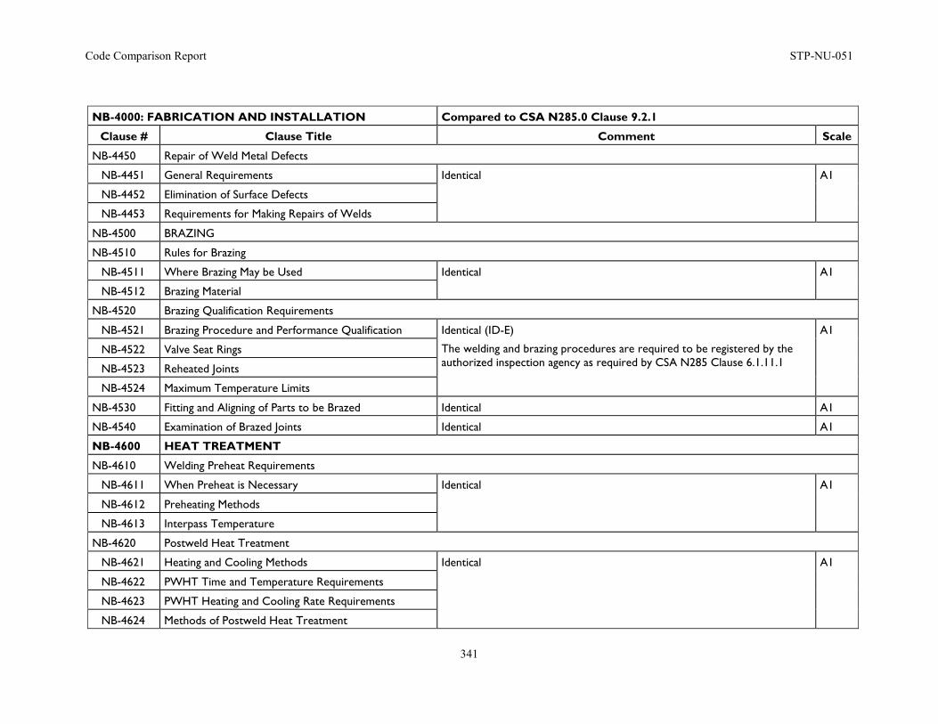
Code Comparison Report STP-NU-051
341
NB-4000: FABRICATION AND INSTALLATION Compared to CSA N285.0 Clause 9.2.1
Clause # Clause Title Comment Scale
NB-4450 Repair of Weld Metal Defects
NB-4451 General Requirements Identical A1
NB-4452 Elimination of Surface Defects
NB-4453 Requirements for Making Repairs of Welds
NB-4500 BRAZING
NB-4510 Rules for Brazing
NB-4511 Where Brazing May be Used Identical A1
NB-4512 Brazing Material
NB-4520 Brazing Qualification Requirements
NB-4521 Brazing Procedure and Performance Qualification Identical (ID-E)
The welding and brazing procedures are required to be registered by the authorized inspection agency as required by CSA N285 Clause 6.1.11.1
A1
NB-4522 Valve Seat Rings
NB-4523 Reheated Joints
NB-4524 Maximum Temperature Limits
NB-4530 Fitting and Aligning of Parts to be Brazed Identical A1
NB-4540 Examination of Brazed Joints Identical A1
NB-4600 HEAT TREATMENT
NB-4610 Welding Preheat Requirements
NB-4611 When Preheat is Necessary Identical A1
NB-4612 Preheating Methods
NB-4613 Interpass Temperature
NB-4620 Postweld Heat Treatment
NB-4621 Heating and Cooling Methods Identical A1
NB-4622 PWHT Time and Temperature Requirements
NB-4623 PWHT Heating and Cooling Rate Requirements
NB-4624 Methods of Postweld Heat Treatment
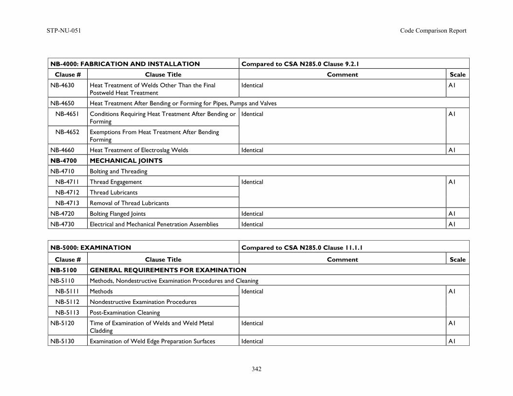
STP-NU-051 Code Comparison Report
342
NB-4000: FABRICATION AND INSTALLATION Compared to CSA N285.0 Clause 9.2.1
Clause # Clause Title Comment Scale
NB-4630 Heat Treatment of Welds Other Than the Final Postweld Heat Treatment
Identical A1
NB-4650 Heat Treatment After Bending or Forming for Pipes, Pumps and Valves
NB-4651 Conditions Requiring Heat Treatment After Bending or Forming
Identical A1
NB-4652 Exemptions From Heat Treatment After Bending Forming
NB-4660 Heat Treatment of Electroslag Welds Identical A1
NB-4700 MECHANICAL JOINTS
NB-4710 Bolting and Threading
NB-4711 Thread Engagement Identical A1
NB-4712 Thread Lubricants
NB-4713 Removal of Thread Lubricants
NB-4720 Bolting Flanged Joints Identical A1
NB-4730 Electrical and Mechanical Penetration Assemblies Identical A1
NB-5000: EXAMINATION Compared to CSA N285.0 Clause 11.1.1
Clause # Clause Title Comment Scale
NB-5100 GENERAL REQUIREMENTS FOR EXAMINATION
NB-5110 Methods, Nondestructive Examination Procedures and Cleaning
NB-5111 Methods Identical A1
NB-5112 Nondestructive Examination Procedures
NB-5113 Post-Examination Cleaning
NB-5120 Time of Examination of Welds and Weld Metal Cladding
Identical A1
NB-5130 Examination of Weld Edge Preparation Surfaces Identical A1
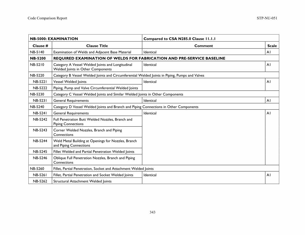
Code Comparison Report STP-NU-051
343
NB-5000: EXAMINATION Compared to CSA N285.0 Clause 11.1.1
Clause # Clause Title Comment Scale
NB-5140 Examination of Welds and Adjacent Base Material Identical A1
NB-5200 REQUIRED EXAMINATION OF WELDS FOR FABRICATION AND PRE-SERVICE BASELINE
NB-5210 Category A Vessel Welded Joints and Longitudinal Welded Joints in Other Components
Identical A1
NB-5220 Category B Vessel Welded Joints and Circumferential Welded Joints in Piping, Pumps and Valves
NB-5221 Vessel Welded Joints Identical A1
NB-5222 Piping, Pump and Valve Circumferential Welded Joints
NB-5230 Category C Vessel Welded Joints and Similar Welded Joints in Other Components
NB-5231 General Requirements Identical A1
NB-5240 Category D Vessel Welded Joints and Branch and Piping Connections in Other Components
NB-5241 General Requirements Identical A1
NB-5242 Full Penetration Butt Welded Nozzles, Branch and Piping Connections
NB-5243 Corner Welded Nozzles, Branch and Piping Connections
NB-5244 Weld Metal Building at Openings for Nozzles, Branch and Piping Connections
NB-5245 Fillet Welded and Partial Penetration Welded Joints
NB-5246 Oblique Full Penetration Nozzles, Branch and Piping Connections
NB-5260 Fillet, Partial Penetration, Socket and Attachment Welded Joints
NB-5261 Fillet, Partial Penetration and Socket Welded Joints Identical A1
NB-5262 Structural Attachment Welded Joints
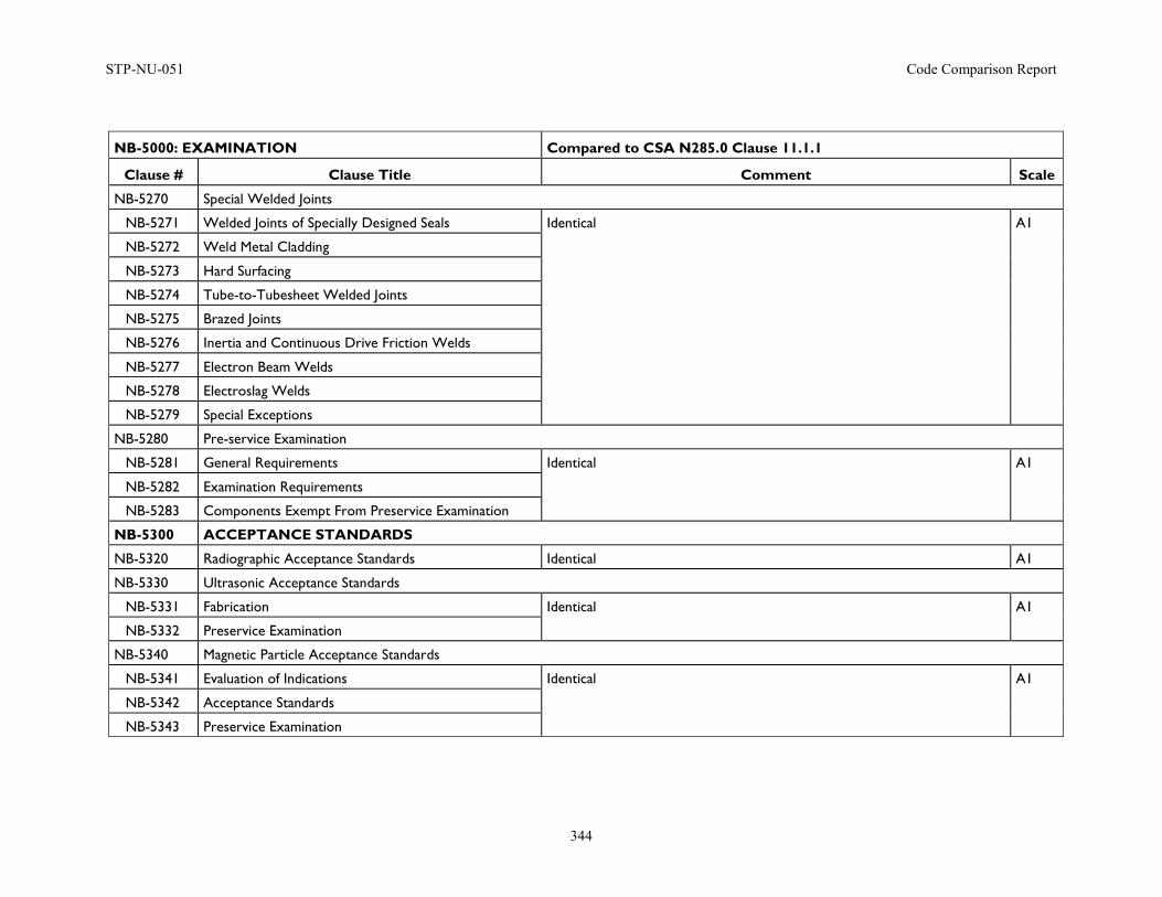
STP-NU-051 Code Comparison Report
344
NB-5000: EXAMINATION Compared to CSA N285.0 Clause 11.1.1
Clause # Clause Title Comment Scale
NB-5270 Special Welded Joints
NB-5271 Welded Joints of Specially Designed Seals Identical A1
NB-5272 Weld Metal Cladding
NB-5273 Hard Surfacing
NB-5274 Tube-to-Tubesheet Welded Joints
NB-5275 Brazed Joints
NB-5276 Inertia and Continuous Drive Friction Welds
NB-5277 Electron Beam Welds
NB-5278 Electroslag Welds
NB-5279 Special Exceptions
NB-5280 Pre-service Examination
NB-5281 General Requirements Identical A1
NB-5282 Examination Requirements
NB-5283 Components Exempt From Preservice Examination
NB-5300 ACCEPTANCE STANDARDS
NB-5320 Radiographic Acceptance Standards Identical A1
NB-5330 Ultrasonic Acceptance Standards
NB-5331 Fabrication Identical A1
NB-5332 Preservice Examination
NB-5340 Magnetic Particle Acceptance Standards
NB-5341 Evaluation of Indications Identical A1
NB-5342 Acceptance Standards
NB-5343 Preservice Examination
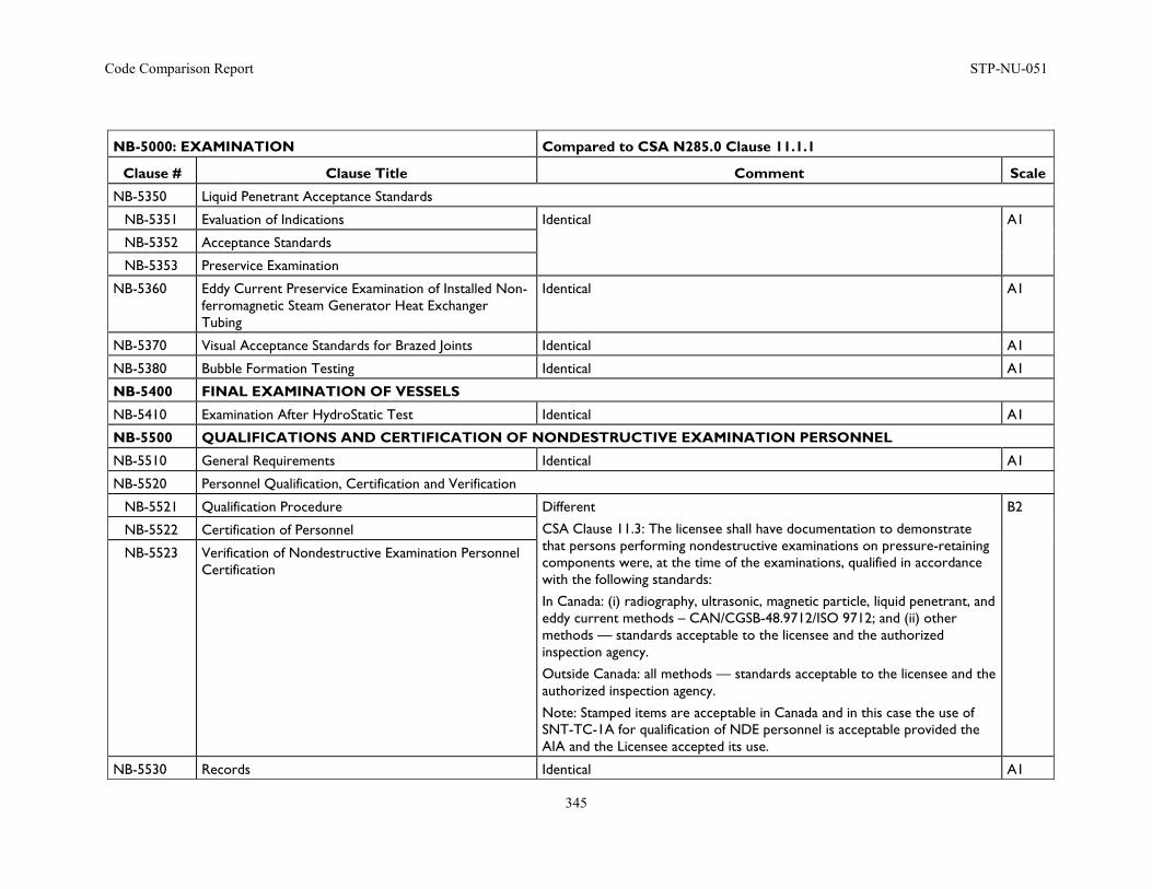
Code Comparison Report STP-NU-051
345
NB-5000: EXAMINATION Compared to CSA N285.0 Clause 11.1.1
Clause # Clause Title Comment Scale
NB-5350 Liquid Penetrant Acceptance Standards
NB-5351 Evaluation of Indications Identical A1
NB-5352 Acceptance Standards
NB-5353 Preservice Examination
NB-5360 Eddy Current Preservice Examination of Installed Non-ferromagnetic Steam Generator Heat Exchanger Tubing
Identical A1
NB-5370 Visual Acceptance Standards for Brazed Joints Identical A1
NB-5380 Bubble Formation Testing Identical A1
NB-5400 FINAL EXAMINATION OF VESSELS
NB-5410 Examination After HydroStatic Test Identical A1
NB-5500 QUALIFICATIONS AND CERTIFICATION OF NONDESTRUCTIVE EXAMINATION PERSONNEL
NB-5510 General Requirements Identical A1
NB-5520 Personnel Qualification, Certification and Verification
NB-5521 Qualification Procedure Different
CSA Clause 11.3: The licensee shall have documentation to demonstrate that persons performing nondestructive examinations on pressure-retaining components were, at the time of the examinations, qualified in accordance with the following standards:
In Canada: (i) radiography, ultrasonic, magnetic particle, liquid penetrant, and eddy current methods – CAN/CGSB-48.9712/ISO 9712; and (ii) other methods — standards acceptable to the licensee and the authorized inspection agency.
Outside Canada: all methods — standards acceptable to the licensee and the authorized inspection agency.
Note: Stamped items are acceptable in Canada and in this case the use of SNT-TC-1A for qualification of NDE personnel is acceptable provided the AIA and the Licensee accepted its use.
B2
NB-5522 Certification of Personnel
NB-5523 Verification of Nondestructive Examination Personnel Certification
NB-5530 Records Identical A1
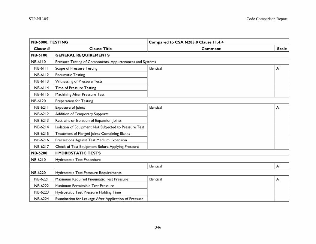
STP-NU-051 Code Comparison Report
346
NB-6000: TESTING Compared to CSA N285.0 Clause 11.4.4
Clause # Clause Title Comment Scale
NB-6100 GENERAL REQUIREMENTS
NB-6110 Pressure Testing of Components, Appurtenances and Systems
NB-6111 Scope of Pressure Testing Identical A1
NB-6112 Pneumatic Testing
NB-6113 Witnessing of Pressure Tests
NB-6114 Time of Pressure Testing
NB-6115 Machining After Pressure Test
NB-6120 Preparation for Testing
NB-6211 Exposure of Joints Identical A1
NB-6212 Addition of Temporary Supports
NB-6213 Restraint or Isolation of Expansion Joints
NB-6214 Isolation of Equipment Not Subjected to Pressure Test
NB-6215 Treatment of Flanged Joints Containing Blanks
NB-6216 Precautions Against Test Medium Expansion
NB-6217 Check of Test Equipment Before Applying Pressure
NB-6200 HYDROSTATIC TESTS
NB-6210 Hydrostatic Test Procedure
Identical A1
NB-6220 Hydrostatic Test Pressure Requirements
NB-6221 Maximum Required Pneumatic Test Pressure Identical A1
NB-6222 Maximum Permissible Test Pressure
NB-6223 Hydrostatic Test Pressure Holding Time
NB-6224 Examination for Leakage After Application of Pressure
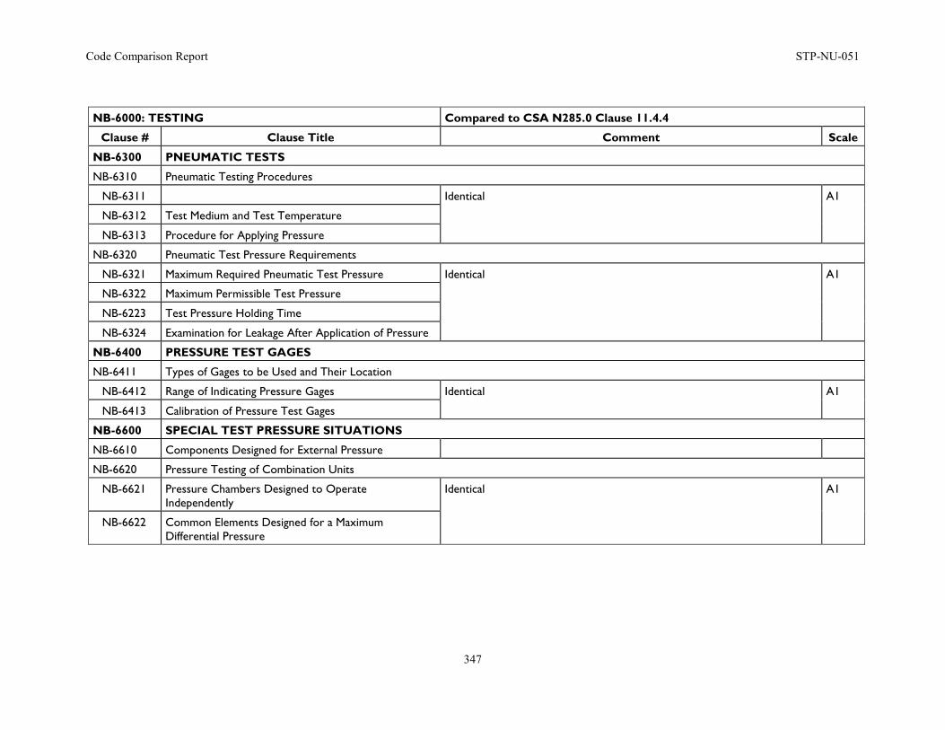
Code Comparison Report STP-NU-051
347
NB-6000: TESTING Compared to CSA N285.0 Clause 11.4.4
Clause # Clause Title Comment Scale
NB-6300 PNEUMATIC TESTS
NB-6310 Pneumatic Testing Procedures
NB-6311 Identical A1
NB-6312 Test Medium and Test Temperature
NB-6313 Procedure for Applying Pressure
NB-6320 Pneumatic Test Pressure Requirements
NB-6321 Maximum Required Pneumatic Test Pressure Identical A1
NB-6322 Maximum Permissible Test Pressure
NB-6223 Test Pressure Holding Time
NB-6324 Examination for Leakage After Application of Pressure
NB-6400 PRESSURE TEST GAGES
NB-6411 Types of Gages to be Used and Their Location
NB-6412 Range of Indicating Pressure Gages Identical A1
NB-6413 Calibration of Pressure Test Gages
NB-6600 SPECIAL TEST PRESSURE SITUATIONS
NB-6610 Components Designed for External Pressure
NB-6620 Pressure Testing of Combination Units
NB-6621 Pressure Chambers Designed to Operate Independently
Identical A1
NB-6622 Common Elements Designed for a Maximum Differential Pressure
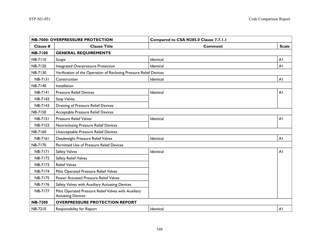
STP-NU-051 Code Comparison Report
348
NB-7000: OVERPRESSURE PROTECTION Compared to CSA N285.0 Clause 7.7.1.1
Clause # Clause Title Comment Scale
NB-7100 GENERAL REQUIREMENTS
NB-7110 Scope Identical A1
NB-7120 Integrated Overpressure Protection Identical A1
NB-7130 Verification of the Operation of Reclosing Pressure Relief Devices
NB-7131 Construction Identical A1
NB-7140 Installation
NB-7141 Pressure Relief Devices Identical A1
NB-7142 Stop Valves
NB-7143 Draining of Pressure Relief Devices
NB-7150 Acceptable Pressure Relief Devices
NB-7151 Pressure Relief Valves Identical A1
NB-7152 Nonreclosing Pressure Relief Devices
NB-7160 Unacceptable Pressure Relief Devices
NB-7161 Deadweight Pressure Relief Valves Identical A1
NB-7170 Permitted Use of Pressure Relief Devices
NB-7171 Safety Valves Identical A1
NB-7172 Safety Relief Valves
NB-7173 Relief Valves
NB-7174 Pilot Operated Pressure Relief Valves
NB-7175 Power Actuated Pressure Relief Valves
NB-7176 Safety Valves with Auxiliary Actuating Devices
NB-7177 Pilot Operated Pressure Relief Valves with Auxiliary Actuating Devices
NB-7200 OVERPRESSURE PROTECTION REPORT
NB-7210 Responsibility for Report Identical A1
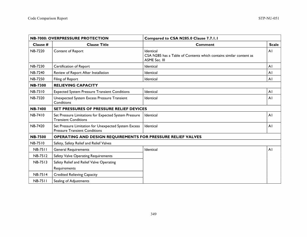
Code Comparison Report STP-NU-051
349
NB-7000: OVERPRESSURE PROTECTION Compared to CSA N285.0 Clause 7.7.1.1
Clause # Clause Title Comment Scale
NB-7220 Content of Report Identical CSA N285 has a Table of Contents which contains similar content as ASME Sec. III
A1
NB-7230 Certification of Report Identical A1
NB-7240 Review of Report After Installation Identical A1
NB-7250 Filing of Report Identical A1
NB-7300 RELIEVING CAPACITY
NB-7310 Expected System Pressure Transient Conditions Identical A1
NB-7320 Unexpected System Excess Pressure Transient Conditions
Identical A1
NB-7400 SET PRESSURES OF PRESSURE RELIEF DEVICES
NB-7410 Set Pressure Limitations for Expected System Pressure Transient Conditions
Identical A1
NB-7420 Set Pressure Limitation for Unexpected System Excess Pressure Transient Conditions
Identical A1
NB-7500 OPERATING AND DESIGN REQUIREMENTS FOR PRESSURE RELIEF VALVES
NB-7510 Safety, Safety Relief and Relief Valves
NB-7511 General Requirements Identical A1
NB-7512 Safety Valve Operating Requirements
NB-7513 Safety Relief and Relief Valve Operating
Requirements
NB-7514 Credited Relieving Capacity
NB-7511 Sealing of Adjustments
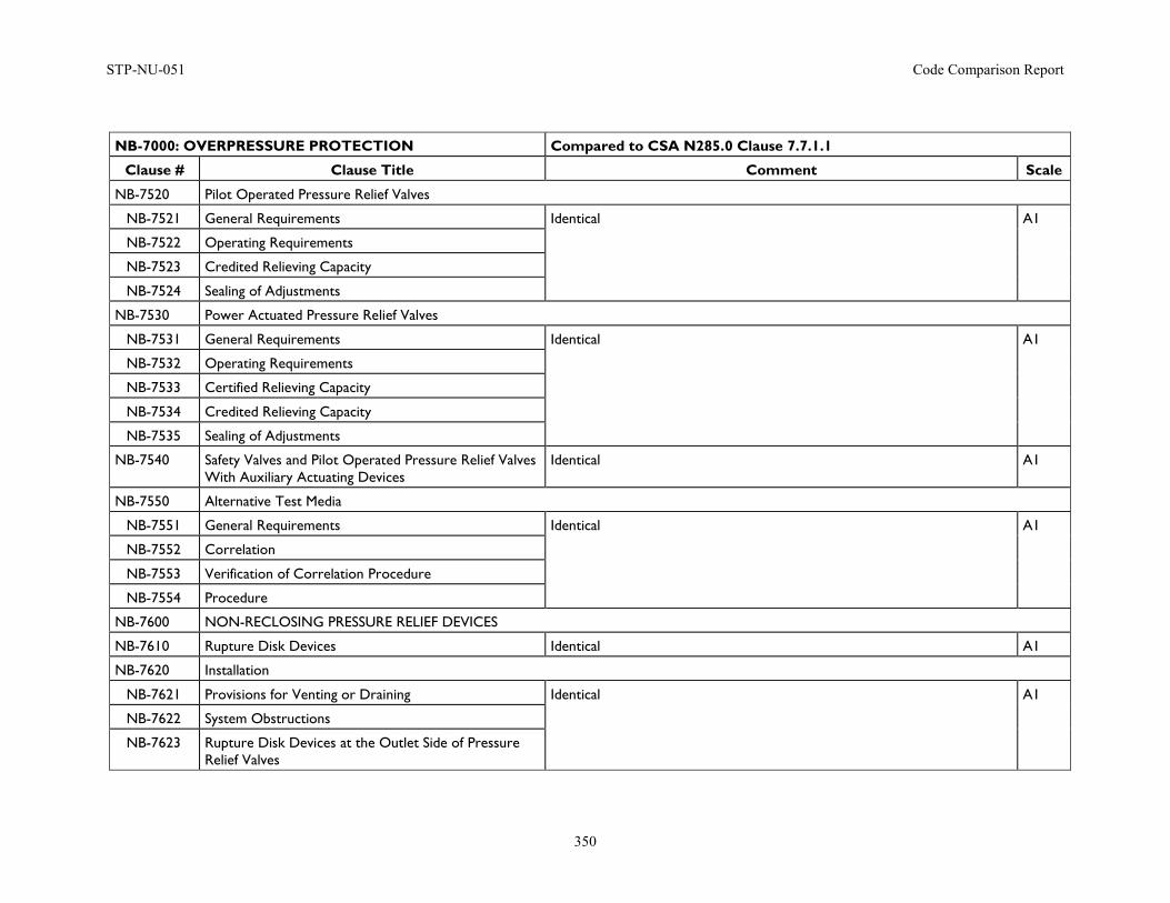
STP-NU-051 Code Comparison Report
350
NB-7000: OVERPRESSURE PROTECTION Compared to CSA N285.0 Clause 7.7.1.1
Clause # Clause Title Comment Scale
NB-7520 Pilot Operated Pressure Relief Valves
NB-7521 General Requirements Identical A1
NB-7522 Operating Requirements
NB-7523 Credited Relieving Capacity
NB-7524 Sealing of Adjustments
NB-7530 Power Actuated Pressure Relief Valves
NB-7531 General Requirements Identical A1
NB-7532 Operating Requirements
NB-7533 Certified Relieving Capacity
NB-7534 Credited Relieving Capacity
NB-7535 Sealing of Adjustments
NB-7540 Safety Valves and Pilot Operated Pressure Relief Valves With Auxiliary Actuating Devices
Identical A1
NB-7550 Alternative Test Media
NB-7551 General Requirements Identical A1
NB-7552 Correlation
NB-7553 Verification of Correlation Procedure
NB-7554 Procedure
NB-7600 NON-RECLOSING PRESSURE RELIEF DEVICES
NB-7610 Rupture Disk Devices Identical A1
NB-7620 Installation
NB-7621 Provisions for Venting or Draining Identical A1
NB-7622 System Obstructions
NB-7623 Rupture Disk Devices at the Outlet Side of Pressure Relief Valves
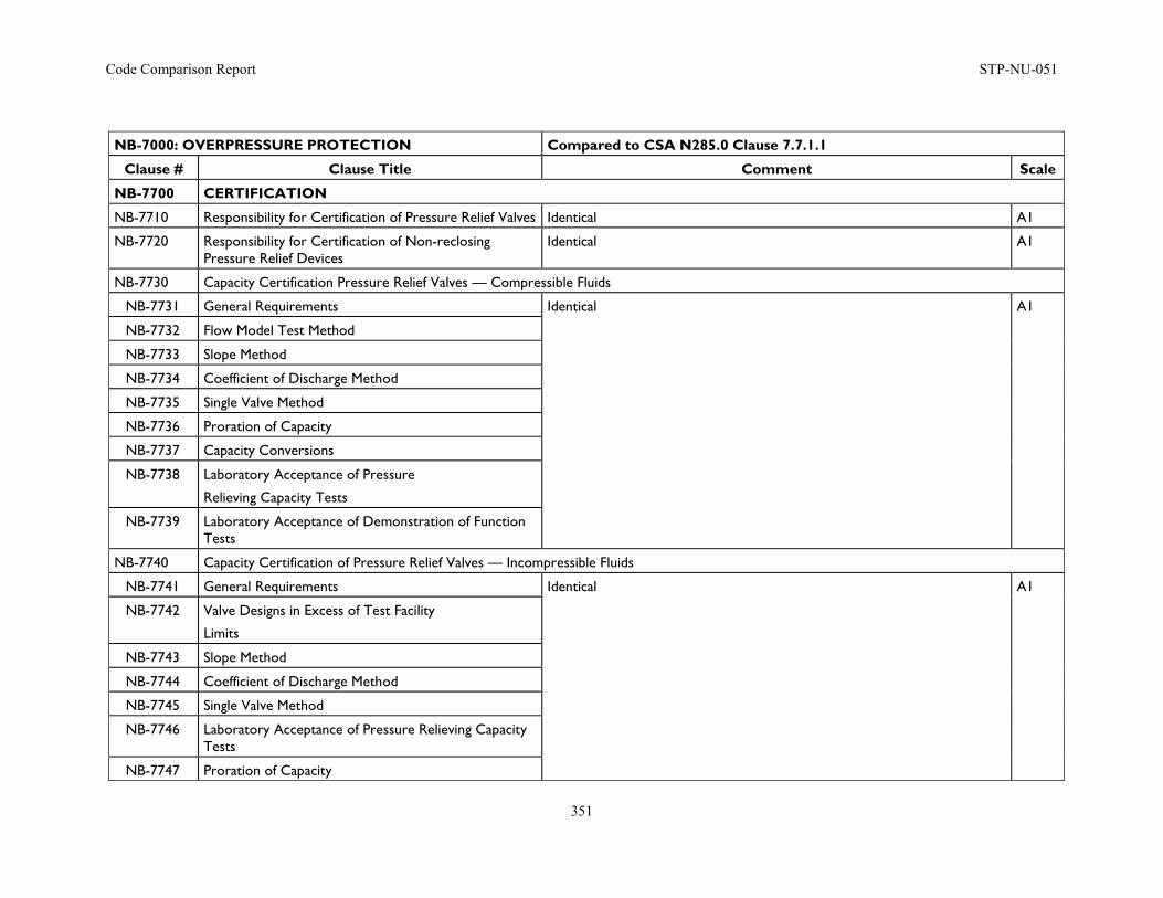
Code Comparison Report STP-NU-051
351
NB-7000: OVERPRESSURE PROTECTION Compared to CSA N285.0 Clause 7.7.1.1
Clause # Clause Title Comment Scale
NB-7700 CERTIFICATION
NB-7710 Responsibility for Certification of Pressure Relief Valves Identical A1
NB-7720 Responsibility for Certification of Non-reclosing Pressure Relief Devices
Identical A1
NB-7730 Capacity Certification Pressure Relief Valves — Compressible Fluids
NB-7731 General Requirements Identical A1
NB-7732 Flow Model Test Method
NB-7733 Slope Method
NB-7734 Coefficient of Discharge Method
NB-7735 Single Valve Method
NB-7736 Proration of Capacity
NB-7737 Capacity Conversions
NB-7738 Laboratory Acceptance of Pressure
Relieving Capacity Tests
NB-7739 Laboratory Acceptance of Demonstration of Function Tests
NB-7740 Capacity Certification of Pressure Relief Valves — Incompressible Fluids
NB-7741 General Requirements Identical A1
NB-7742 Valve Designs in Excess of Test Facility
Limits
NB-7743 Slope Method
NB-7744 Coefficient of Discharge Method
NB-7745 Single Valve Method
NB-7746 Laboratory Acceptance of Pressure Relieving Capacity Tests
NB-7747 Proration of Capacity
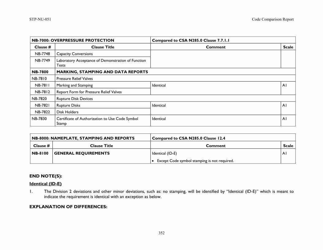
STP-NU-051 Code Comparison Report
352
NB-7000: OVERPRESSURE PROTECTION Compared to CSA N285.0 Clause 7.7.1.1
Clause # Clause Title Comment Scale
NB-7748 Capacity Conversions
NB-7749 Laboratory Acceptance of Demonstration of Function Tests
NB-7800 MARKING, STAMPING AND DATA REPORTS
NB-7810 Pressure Relief Valves
NB-7811 Marking and Stamping Identical A1
NB-7812 Report Form for Pressure Relief Valves
NB-7820 Rupture Disk Devices
NB-7821 Rupture Disks Identical A1
NB-7822 Disk Holders
NB-7830 Certificate of Authorization to Use Code Symbol Stamp
Identical A1
NB-8000: NAMEPLATE, STAMPING AND REPORTS Compared to CSA N285.0 Clause 12.4
Clause # Clause Title Comment Scale
NB-8100 GENERAL REQUIREMENTS Identical (ID-E)
• Except Code symbol stamping is not required.
A1
END NOTE(S):
Identical (ID-E)
1. The Division 2 deviations and other minor deviations, such as: no stamping, will be identified by “Identical (ID-E)” which is meant to indicate the requirement is identical with an exception as below.
EXPLANATION OF DIFFERENCES:
Code Comparison Report STP-NU-051
353
ASME BPV Code Section III, Subsection NB, Division 1 was compared against CSA Standard N285.0-08 (Update # 2). The summary of these differences are noted below:
1. CSA Standard N285.0, Annex I has requirements for penetration
2. CANDU Nuclear Power Plants specific Materials which are not covered by the rules of ASME, rules are provided by the CSA N285.6.
3. The welding and brazing procedures are required to be registered with the authorized inspection agency as required by CSA N285 Clause 6.1.11.1
4. CSA Clause 11.3: The licensee shall have documentation to demonstrate that persons performing nondestructive examinations on pressure-retaining components were, at the time of the examinations, qualified in accordance with the following standards:
In Canada: (i) radiography, ultrasonic, magnetic particle, liquid penetrant, and eddy current methods – CAN/CGSB-48.9712/ISO 9712; and (ii) other methods — standards acceptable to the licensee and the authorized inspection agency.
Outside Canada: all methods — standards acceptable to the licensee and the authorized inspection agency.
Note: Stamped items are acceptable in Canada and in this case the use of SNT-TC-1A for qualification of NDE personnel is acceptable provided the AIA and the Licensee accepted its use.
5. CSA N285 has a Table of Contents which contains similar content as ASME BPV Code Section III
6. CSA N285 does not require Code symbol stamping
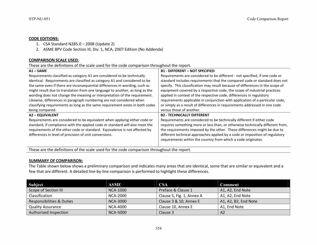
STP-NU-051 Code Comparison Report
354
CODE EDITIONS: 1. CSA Standard N285.0 – 2008 (Update 2) 2. ASME BPV Code Section III, Div. 1, NCA, 2007 Edition (No Addenda)
COMPARISON SCALE USED: These are the definitions of the scale used for the code comparison throughout the report. A1 – SAME Requirements classified as category A1 are considered to be technically identical. Requirements are classified as category A1 and considered to be the same even if there are inconsequential differences in wording, such as might result due to translation from one language to another, as long as the wording does not change the meaning or interpretation of the requirement. Likewise, differences in paragraph numbering are not considered when classifying requirements as long as the same requirement exists in both codes being compared.
B1 - DIFFERENT – NOT SPECIFIED Requirements are considered to be different - not specified, if one code or standard includes requirements that the compared code or standard does not specify. This classification may result because of differences in the scope of equipment covered by a respective code, the scope of industrial practices applied in context of the respective code, differences in regulatory requirements applicable in conjunction with application of a particular code, or simply as a result of differences in requirements addressed in one code versus those of another.
A2 – EQUIVALENT Requirements are considered to be equivalent when applying either code or standard, if compliance with the applied code or standard will also meet the requirements of the other code or standard. Equivalence is not affected by differences in level of precision of unit conversions.
B2 - TECHNICALLY DIFFERENT Requirements are considered to be technically different if either code requires something more or less than, or otherwise technically different from, the requirements imposed by the other. These differences might be due to different technical approaches applied by a code or imposition of regulatory requirements within the country from which a code originates.
These are the definitions of the scale used for the code comparison throughout the report. SUMMARY OF COMPARISON: The Table shown below shows a preliminary comparison and indicates many areas that are identical, some that are similar or equivalent and a few that are different. A detailed line-by-line comparison is performed to highlight these differences.
Subject ASME CSA Comment Scope of Section III NCA-1000 Preface & Clause 1 A1, A2, End Note Classification NCA-2000 Clause 5, Fig. 1, Annex A A1, A2, End Note Responsibilities & Duties NCA-3000 Clause 3 & 10, Annex E A1, A2, B2, End Note Quality Assurance NCA-4000 Clause 10, Annex E A1, End Note Authorized Inspection NCA-5000 Clause 3 A2
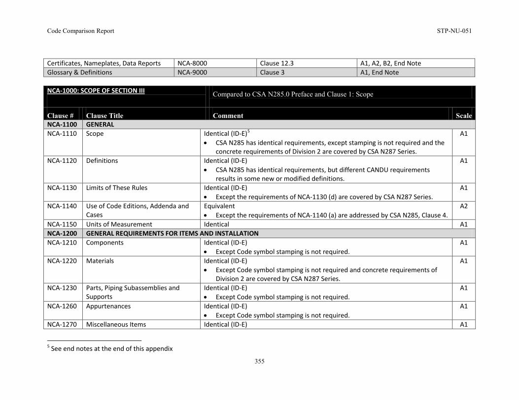
Code Comparison Report STP-NU-051
355
Certificates, Nameplates, Data Reports NCA-8000 Clause 12.3 A1, A2, B2, End Note Glossary & Definitions NCA-9000 Clause 3 A1, End Note NCA-1000: SCOPE OF SECTION III
Compared to CSA N285.0 Preface and Clause 1: Scope
Clause # Clause Title Comment Scale NCA-1100 GENERAL NCA-1110 Scope Identical (ID-E)5
• CSA N285 has identical requirements, except stamping is not required and the concrete requirements of Division 2 are covered by CSA N287 Series.
A1
NCA-1120 Definitions Identical (ID-E) • CSA N285 has identical requirements, but different CANDU requirements
results in some new or modified definitions.
A1
NCA-1130 Limits of These Rules Identical (ID-E) • Except the requirements of NCA-1130 (d) are covered by CSA N287 Series.
A1
NCA-1140 Use of Code Editions, Addenda and Cases
Equivalent • Except the requirements of NCA-1140 (a) are addressed by CSA N285, Clause 4.
A2
NCA-1150 Units of Measurement Identical A1 NCA-1200 GENERAL REQUIREMENTS FOR ITEMS AND INSTALLATION NCA-1210 Components Identical (ID-E)
• Except Code symbol stamping is not required. A1
NCA-1220 Materials Identical (ID-E) • Except Code symbol stamping is not required and concrete requirements of
Division 2 are covered by CSA N287 Series.
A1
NCA-1230 Parts, Piping Subassemblies and Supports
Identical (ID-E) • Except Code symbol stamping is not required.
A1
NCA-1260 Appurtenances Identical (ID-E) • Except Code symbol stamping is not required.
A1
NCA-1270 Miscellaneous Items Identical (ID-E) A1
5 See end notes at the end of this appendix
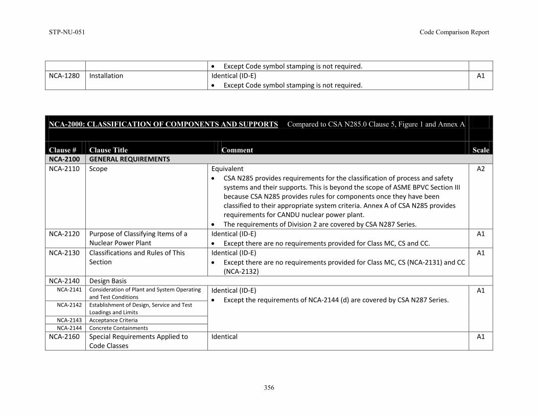
STP-NU-051 Code Comparison Report
356
• Except Code symbol stamping is not required. NCA-1280 Installation Identical (ID-E)
• Except Code symbol stamping is not required. A1
NCA-2000: CLASSIFICATION OF COMPONENTS AND SUPPORTS Compared to CSA N285.0 Clause 5, Figure 1 and Annex A
Clause # Clause Title Comment Scale NCA-2100 GENERAL REQUIREMENTS NCA-2110 Scope Equivalent
• CSA N285 provides requirements for the classification of process and safety systems and their supports. This is beyond the scope of ASME BPVC Section III because CSA N285 provides rules for components once they have been classified to their appropriate system criteria. Annex A of CSA N285 provides requirements for CANDU nuclear power plant.
• The requirements of Division 2 are covered by CSA N287 Series.
A2
NCA-2120 Purpose of Classifying Items of a Nuclear Power Plant
Identical (ID-E) • Except there are no requirements provided for Class MC, CS and CC.
A1
NCA-2130 Classifications and Rules of This Section
Identical (ID-E) • Except there are no requirements provided for Class MC, CS (NCA-2131) and CC
(NCA-2132)
A1
NCA-2140 Design Basis NCA-2141 Consideration of Plant and System Operating
and Test Conditions Identical (ID-E) • Except the requirements of NCA-2144 (d) are covered by CSA N287 Series.
A1
NCA-2142 Establishment of Design, Service and Test Loadings and Limits
NCA-2143 Acceptance Criteria NCA-2144 Concrete Containments
NCA-2160 Special Requirements Applied to Code Classes
Identical A1
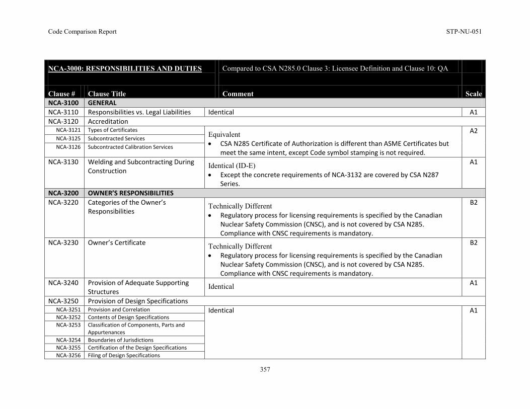
Code Comparison Report STP-NU-051
357
NCA-3000: RESPONSIBILITIES AND DUTIES
Compared to CSA N285.0 Clause 3: Licensee Definition and Clause 10: QA
Clause # Clause Title Comment Scale NCA-3100 GENERAL NCA-3110 Responsibilities vs. Legal Liabilities Identical A1 NCA-3120 Accreditation
NCA-3121 Types of Certificates Equivalent • CSA N285 Certificate of Authorization is different than ASME Certificates but
meet the same intent, except Code symbol stamping is not required.
A2 NCA-3125 Subcontracted Services NCA-3126 Subcontracted Calibration Services
NCA-3130 Welding and Subcontracting During Construction
Identical (ID-E) • Except the concrete requirements of NCA-3132 are covered by CSA N287
Series.
A1
NCA-3200 OWNER’S RESPONSIBILITIES NCA-3220 Categories of the Owner’s
Responsibilities Technically Different • Regulatory process for licensing requirements is specified by the Canadian
Nuclear Safety Commission (CNSC), and is not covered by CSA N285. Compliance with CNSC requirements is mandatory.
B2
NCA-3230 Owner’s Certificate Technically Different • Regulatory process for licensing requirements is specified by the Canadian
Nuclear Safety Commission (CNSC), and is not covered by CSA N285. Compliance with CNSC requirements is mandatory.
B2
NCA-3240 Provision of Adequate Supporting Structures
Identical A1
NCA-3250 Provision of Design Specifications NCA-3251 Provision and Correlation Identical A1 NCA-3252 Contents of Design Specifications NCA-3253 Classification of Components, Parts and
Appurtenances NCA-3254 Boundaries of Jurisdictions NCA-3255 Certification of the Design Specifications NCA-3256 Filing of Design Specifications
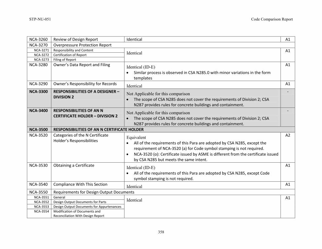
STP-NU-051 Code Comparison Report
358
NCA-3260 Review of Design Report Identical A1 NCA-3270 Overpressure Protection Report
NCA-3271 Responsibility and Content Identical A1
NCA-3272 Certification of Report NCA-3273 Filing of Report
NCA-3280 Owner’s Data Report and Filing Identical (ID-E) • Similar process is observed in CSA N285.0 with minor variations in the form
templates
A1
NCA-3290 Owner’s Responsibility for Records Identical A1
NCA-3300 RESPONSIBILITIES OF A DESIGNER – DIVISION 2
Not Applicable for this comparison • The scope of CSA N285 does not cover the requirements of Division 2; CSA
N287 provides rules for concrete buildings and containment.
-
NCA-3400 RESPONSIBILITIES OF AN N CERTIFICATE HOLDER – DIVISION 2
Not Applicable for this comparison • The scope of CSA N285 does not cover the requirements of Division 2; CSA
N287 provides rules for concrete buildings and containment.
-
NCA-3500 RESPONSIBILITIES OF AN N CERTIFICATE HOLDER NCA-3520 Categories of the N Certificate
Holder’s Responsibilities Equivalent • All of the requirements of this Para are adopted by CSA N285, except the
requirement of NCA-3520 (a) for Code symbol stamping is not required. • NCA-3520 (o): Certificate issued by ASME is different from the certificate issued
by CSA N285 but meets the same intent.
A2
NCA-3530 Obtaining a Certificate Identical (ID-E) • All of the requirements of this Para are adopted by CSA N285, except Code
symbol stamping is not required.
A1
NCA-3540 Compliance With This Section Identical A1
NCA-3550 Requirements for Design Output Documents NCA-3551 General
Identical A1 NCA-3552 Design Output Documents for Parts NCA-3553 Design Output Documents for Appurtenances NCA-3554 Modification of Documents and
Reconciliation With Design Report
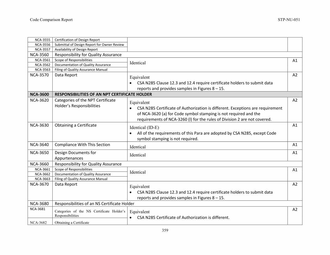
Code Comparison Report STP-NU-051
359
NCA-3555 Certification of Design Report NCA-3556 Submittal of Design Report for Owner Review NCA-3557 Availability of Design Report
NCA-3560 Responsibility for Quality Assurance NCA-3561 Scope of Responsibilities
Identical A1 NCA-3562 Documentation of Quality Assurance NCA-3563 Filing of Quality Assurance Manual
NCA-3570 Data Report Equivalent • CSA N285 Clause 12.3 and 12.4 require certificate holders to submit data
reports and provides samples in Figures 8 – 15.
A2
NCA-3600 RESPONSIBILITIES OF AN NPT CERTIFICATE HOLDER NCA-3620 Categories of the NPT Certificate
Holder’s Responsibilities Equivalent • CSA N285 Certificate of Authorization is different. Exceptions are requirement
of NCA-3620 (a) for Code symbol stamping is not required and the requirements of NCA-3260 (l) for the rules of Division 2 are not covered.
A2
NCA-3630 Obtaining a Certificate Identical (ID-E) • All of the requirements of this Para are adopted by CSA N285, except Code
symbol stamping is not required.
A1
NCA-3640 Compliance With This Section Identical A1
NCA-3650 Design Documents for Appurtenances
Identical A1
NCA-3660 Responsibility for Quality Assurance NCA-3661 Scope of Responsibilities
Identical A1 NCA-3662 Documentation of Quality Assurance NCA-3663 Filing of Quality Assurance Manual
NCA-3670 Data Report Equivalent • CSA N285 Clause 12.3 and 12.4 require certificate holders to submit data
reports and provides samples in Figures 8 – 15.
A2
NCA-3680 Responsibilities of an NS Certificate Holder NCA-3681 Categories of the NS Certificate Holder’s
Responsibilities Equivalent • CSA N285 Certificate of Authorization is different.
A2
NCA-3682 Obtaining a Certificate
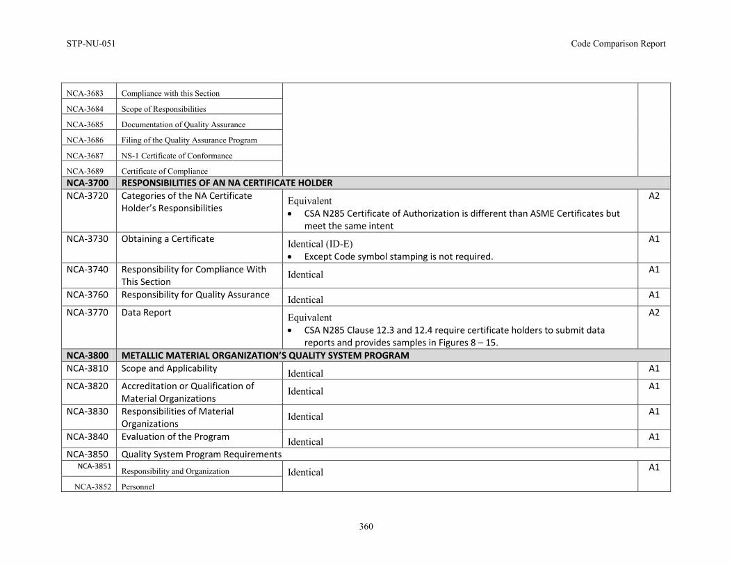
STP-NU-051 Code Comparison Report
360
NCA-3683 Compliance with this Section
NCA-3684 Scope of Responsibilities
NCA-3685 Documentation of Quality Assurance
NCA-3686 Filing of the Quality Assurance Program
NCA-3687 NS-1 Certificate of Conformance
NCA-3689 Certificate of Compliance NCA-3700 RESPONSIBILITIES OF AN NA CERTIFICATE HOLDER NCA-3720 Categories of the NA Certificate
Holder’s Responsibilities Equivalent • CSA N285 Certificate of Authorization is different than ASME Certificates but
meet the same intent
A2
NCA-3730 Obtaining a Certificate Identical (ID-E) • Except Code symbol stamping is not required.
A1
NCA-3740 Responsibility for Compliance With This Section
Identical A1
NCA-3760 Responsibility for Quality Assurance Identical A1
NCA-3770 Data Report Equivalent • CSA N285 Clause 12.3 and 12.4 require certificate holders to submit data
reports and provides samples in Figures 8 – 15.
A2
NCA-3800 METALLIC MATERIAL ORGANIZATION’S QUALITY SYSTEM PROGRAM NCA-3810 Scope and Applicability Identical A1
NCA-3820 Accreditation or Qualification of Material Organizations
Identical A1
NCA-3830 Responsibilities of Material Organizations
Identical A1
NCA-3840 Evaluation of the Program Identical A1
NCA-3850 Quality System Program Requirements NCA-3851 Responsibility and Organization Identical A1
NCA-3852 Personnel
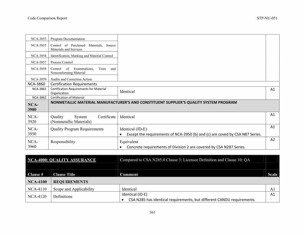
Code Comparison Report STP-NU-051
361
NCA-3853 Program Documentation
NCA-3855 Control of Purchased Materials, Source Materials and Services
NCA-3856 Identification, Marking and Material Control
NCA-3857 Process Control
NCA-3858 Control of Examinations, Tests and Nonconforming Material
NCA-3859 Audits and Correction Action NCA-3860 Certification Requirements
NCA-3861 Certification Requirements for Material Organization Identical A1
NCA-3862 Certification of Material
NCA-3900
NONMETALLIC MATERIAL MANUFACTURER’S AND CONSTITUENT SUPPLIER’S QUALITY SYSTEM PROGRAM
NCA-3920
Quality System Certificate (Nonmetallic Materials)
Identical A1
NCA-3950
Quality Program Requirements Identical (ID-E) • Except the requirements of NCA-3950 (b) and (c) are coved by CSA N87 Series.
A1
NCA-3960
Responsibility Equivalent • Concrete requirements of Division 2 are covered by CSA N287 Series.
A2
NCA-4000: QUALITY ASSURANCE
Compared to CSA N285.0 Clause 3: Licensee Definition and Clause 10: QA
Clause # Clause Title Comment Scale
NCA-4100 REQUIREMENTS
NCA-4110 Scope and Applicability Identical A1
NCA-4120 Definitions Identical (ID-E) • CSA N285 has identical requirements, but different CANDU requirements
A1
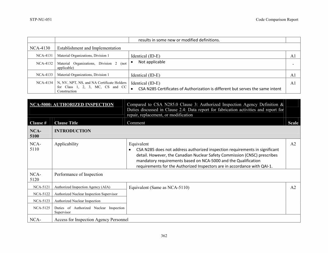
STP-NU-051 Code Comparison Report
362
results in some new or modified definitions.
NCA-4130 Establishment and Implementation NCA-4131 Material Organizations, Division 1 Identical (ID-E) A1 NCA-4132 Material Organizations, Division 2 (not
applicable) • Not applicable -
NCA-4133 Material Organizations, Division 1 Identical (ID-E) A1 NCA-4134 N, NV, NPT, NS, and NA Certificate Holders
for Class 1, 2, 3, MC, CS and CC Construction
Identical (ID-E) • CSA N285 Certificates of Authorization is different but serves the same intent
A1
NCA-5000: AUTHORIZED INSPECTION
Compared to CSA N285.0 Clause 3: Authorized Inspection Agency Definition & Duties discussed in Clause 2.4: Data report for fabrication activities and report for repair, replacement, or modification
Clause # Clause Title Comment Scale
NCA-5100
INTRODUCTION
NCA-5110
Applicability Equivalent • CSA N285 does not address authorized inspection requirements in significant
detail. However, the Canadian Nuclear Safety Commission (CNSC) prescribes mandatory requirements based on NCA-5000 and the Qualification requirements for the Authorized Inspectors are in accordance with QAI-1.
A2
NCA-5120
Performance of Inspection
NCA-5121 Authorized Inspection Agency (AIA) Equivalent (Same as NCA-5110) A2 NCA-5122 Authorized Nuclear Inspection Supervisor
NCA-5123 Authorized Nuclear Inspection
NCA-5125 Duties of Authorized Nuclear Inspection Supervisor
NCA- Access for Inspection Agency Personnel
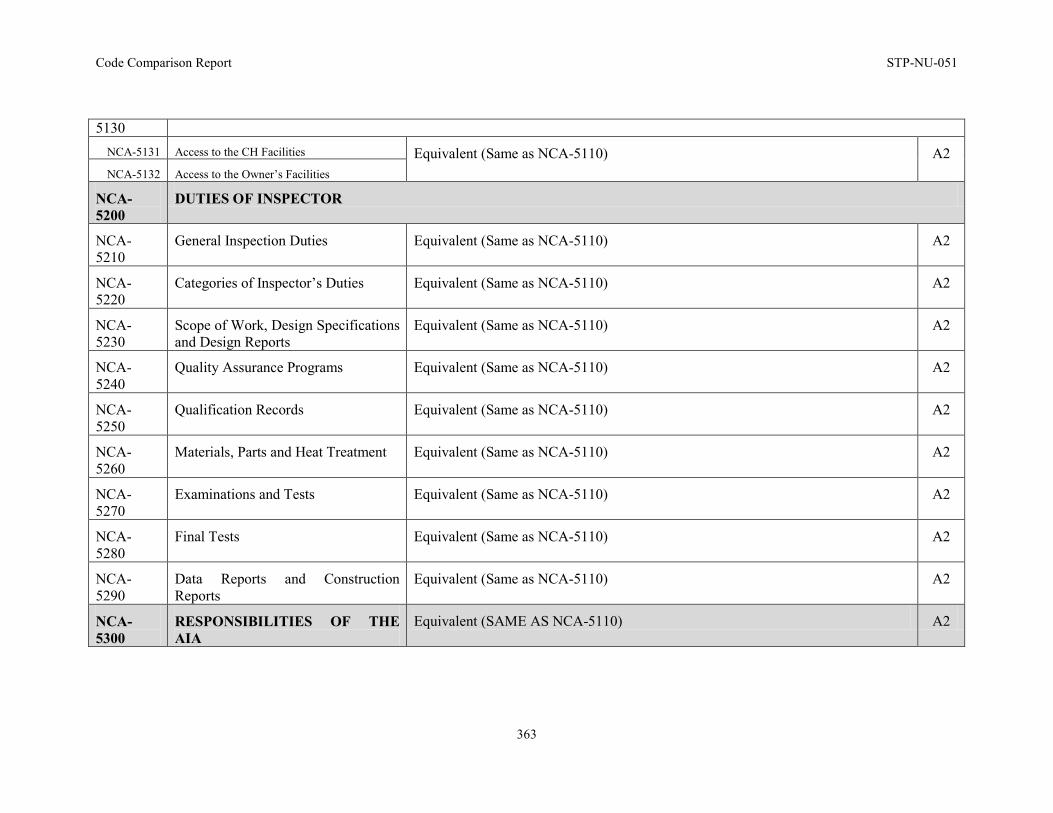
Code Comparison Report STP-NU-051
363
5130 NCA-5131 Access to the CH Facilities Equivalent (Same as NCA-5110) A2 NCA-5132 Access to the Owner’s Facilities
NCA-5200
DUTIES OF INSPECTOR
NCA-5210
General Inspection Duties Equivalent (Same as NCA-5110) A2
NCA-5220
Categories of Inspector’s Duties Equivalent (Same as NCA-5110) A2
NCA-5230
Scope of Work, Design Specifications and Design Reports
Equivalent (Same as NCA-5110) A2
NCA-5240
Quality Assurance Programs Equivalent (Same as NCA-5110) A2
NCA-5250
Qualification Records Equivalent (Same as NCA-5110) A2
NCA-5260
Materials, Parts and Heat Treatment Equivalent (Same as NCA-5110) A2
NCA-5270
Examinations and Tests Equivalent (Same as NCA-5110) A2
NCA-5280
Final Tests Equivalent (Same as NCA-5110) A2
NCA-5290
Data Reports and Construction Reports
Equivalent (Same as NCA-5110) A2
NCA-5300
RESPONSIBILITIES OF THE AIA
Equivalent (SAME AS NCA-5110) A2
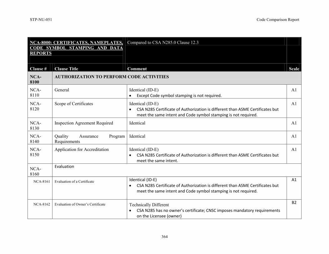
STP-NU-051 Code Comparison Report
364
NCA-8000: CERTIFICATES, NAMEPLATES, CODE SYMBOL STAMPING AND DATA REPORTS
Compared to CSA N285.0 Clause 12.3
Clause # Clause Title Comment Scale
NCA-8100
AUTHORIZATION TO PERFORM CODE ACTIVITIES
NCA-8110
General Identical (ID-E) • Except Code symbol stamping is not required.
A1
NCA-8120
Scope of Certificates Identical (ID-E) • CSA N285 Certificate of Authorization is different than ASME Certificates but
meet the same intent and Code symbol stamping is not required.
A1
NCA-8130
Inspection Agreement Required Identical A1
NCA-8140
Quality Assurance Program Requirements
Identical A1
NCA-8150
Application for Accreditation Identical (ID-E) • CSA N285 Certificate of Authorization is different than ASME Certificates but
meet the same intent.
A1
NCA-8160
Evaluation
NCA-8161 Evaluation of a Certificate Identical (ID-E) • CSA N285 Certificate of Authorization is different than ASME Certificates but
meet the same intent and Code symbol stamping is not required.
A1
NCA-8162 Evaluation of Owner’s Certificate Technically Different • CSA N285 has no owner’s certificate; CNSC imposes mandatory requirements
on the Licensee (owner)
B2
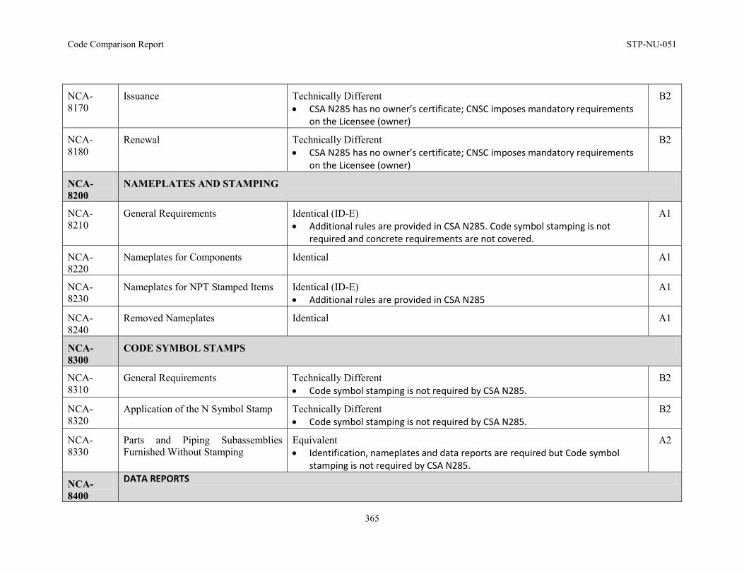
Code Comparison Report STP-NU-051
365
NCA-8170
Issuance Technically Different • CSA N285 has no owner’s certificate; CNSC imposes mandatory requirements
on the Licensee (owner)
B2
NCA-8180
Renewal Technically Different • CSA N285 has no owner’s certificate; CNSC imposes mandatory requirements
on the Licensee (owner)
B2
NCA-8200
NAMEPLATES AND STAMPING
NCA-8210
General Requirements Identical (ID-E) • Additional rules are provided in CSA N285. Code symbol stamping is not
required and concrete requirements are not covered.
A1
NCA-8220
Nameplates for Components Identical A1
NCA-8230
Nameplates for NPT Stamped Items Identical (ID-E) • Additional rules are provided in CSA N285
A1
NCA-8240
Removed Nameplates Identical A1
NCA-8300
CODE SYMBOL STAMPS
NCA-8310
General Requirements Technically Different • Code symbol stamping is not required by CSA N285.
B2
NCA-8320
Application of the N Symbol Stamp Technically Different • Code symbol stamping is not required by CSA N285.
B2
NCA-8330
Parts and Piping Subassemblies Furnished Without Stamping
Equivalent • Identification, nameplates and data reports are required but Code symbol
stamping is not required by CSA N285.
A2
NCA-8400
DATA REPORTS
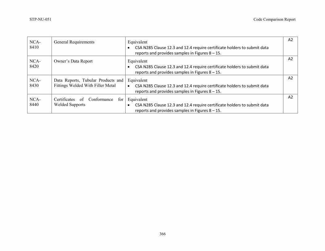
STP-NU-051 Code Comparison Report
366
NCA-8410
General Requirements Equivalent • CSA N285 Clause 12.3 and 12.4 require certificate holders to submit data
reports and provides samples in Figures 8 – 15.
A2
NCA-8420
Owner’s Data Report Equivalent • CSA N285 Clause 12.3 and 12.4 require certificate holders to submit data
reports and provides samples in Figures 8 – 15.
A2
NCA-8430
Data Reports, Tubular Products and Fittings Welded With Filler Metal
Equivalent • CSA N285 Clause 12.3 and 12.4 require certificate holders to submit data
reports and provides samples in Figures 8 – 15.
A2
NCA-8440
Certificates of Conformance for Welded Supports
Equivalent • CSA N285 Clause 12.3 and 12.4 require certificate holders to submit data
reports and provides samples in Figures 8 – 15.
A2
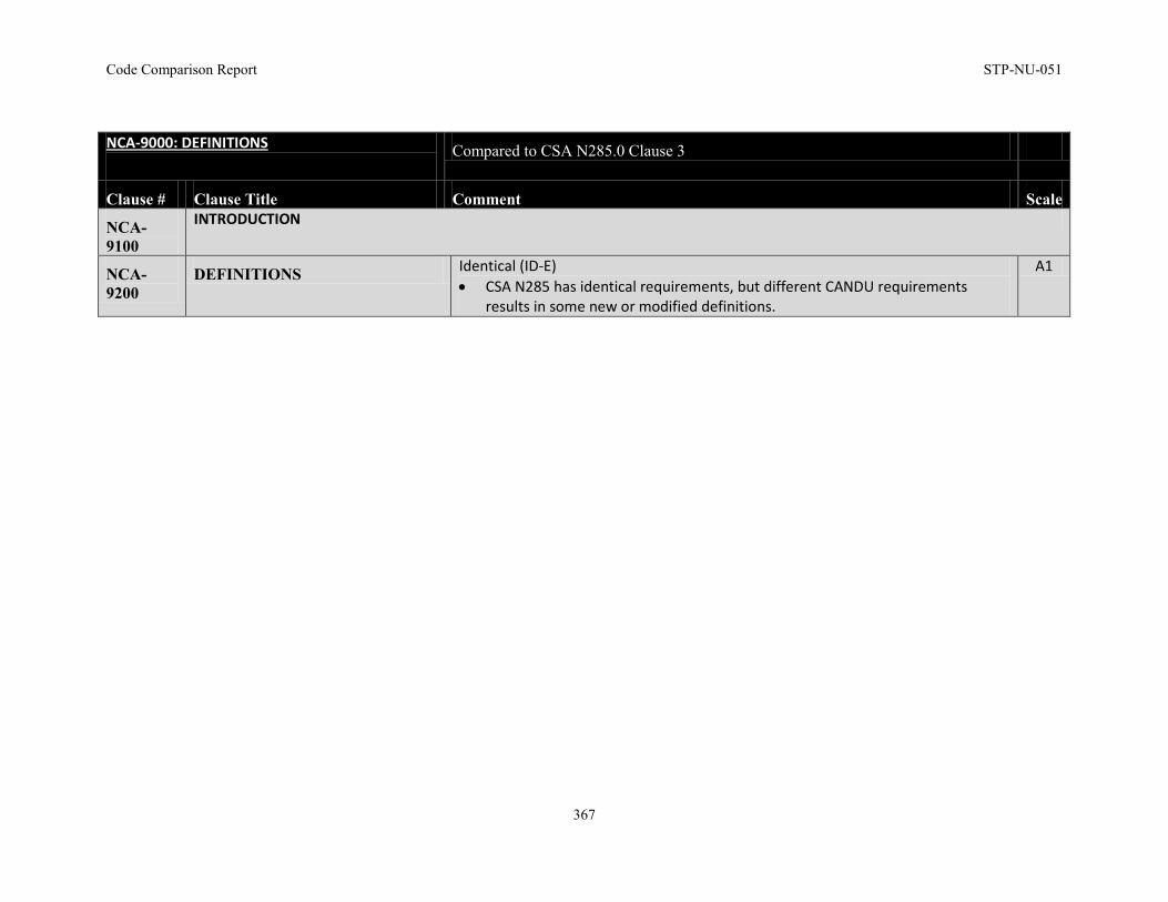
Code Comparison Report STP-NU-051
367
NCA-9000: DEFINITIONS
Compared to CSA N285.0 Clause 3
Clause # Clause Title Comment Scale
NCA-9100
INTRODUCTION
NCA-9200
DEFINITIONS Identical (ID-E) • CSA N285 has identical requirements, but different CANDU requirements
results in some new or modified definitions.
A1
STP-NU-051 Code Comparison Report
368
END NOTE(S): Identical (ID-E): 1 The Division 2 deviations and other minor deviations, such as: no stamping, will be identified by “Identical (ID-E)” which is
meant to indicate the requirement is identical with an exception as below.
EXPLANATION OF DIFFERENCES: ASME BPV Code Section III, Subsection NCA, Division 1 was compared against CSA Standard N285.0-08 (Update # 2), the observed differences are summarized below: 1. CSA N285 does not require Code symbol stamping
2. Concrete requirements of Division 2 are covered by CSA N287 Series
3. CSA N285 provides requirements for the classification of process and safety systems and their supports. This is beyond the scope of ASME
BPVC Section III because CSA N285 provides rules for components once they have been classified to their appropriate system criteria. Annex
A of CSA N285 provides requirements for CANDU nuclear power plant
4. CSA N285 does not provide requirements for Class MC, CS and CC
5. CSA N285 Certificate of Authorization is different than ASME Certificates but meet the same intent
6. Regulatory process for licensing requirements is specified by the Canadian Nuclear Safety Commission (CNSC), and is not covered by CSA
N285. Compliance with CNSC requirements is mandatory
7. Similar process is observed for the Owner’s review of the Data Report in CSA N285.0 with minor variations in the form templates
8. CSA N285 Clause 12.3 and 12.4 require certificate holders to submit data reports and provides samples in Figures 8 – 15
9. CSA N285 does not address authorized inspection requirements in significant detail. However, the Canadian Nuclear Safety Commission
(CNSC) prescribes mandatory requirements based on NCA-5000 and the Qualification requirements for the Authorized Inspectors are in
accordance with QAI-1
10. CSA N285 has no owner’s certificate; CNSC imposes mandatory requirements on the Licensee (owner)

A2241Q