3.1 executive summary - brookhaven national laboratory …€¦ · · 2010-12-29splitting the...
TRANSCRIPT

Experimental Facilities Chapter 3: CHX – Coherent Hard X-ray Beamline 3-1
NSLS-II Preliminary Design Document
3.1 Executive Summary
This section provides an overview of the conceptual design of the Coherent Hard X-Ray (CHX) Beamline at NSLS-II at Brookhaven National Laboratory. The high coherent flux that will be available at this beamline will enable state-of-the-art investigations of the dynamics and structure of disordered materials.
The technique will take advantage of very high flux of the NSLS-II source. The basic concept of the proposed design of the CHX beamline is to substitute the intrinsic source with a secondary source that is controlled by the end user. A secondary source is employed only in the horizontal direction. The aim is to enlarge the lateral coherence seen at the sample position and bring the horizontal and vertical coherence lengths closer to each other [1]. The beamline design embraces two branches, the small angle branch and the coherent diffraction and large angle branch, although just one of these branches (the small angle branch) will be built as part of the NSLS-II project. The edges of the mirrors will be used to separate the branches. The main energy range for the beamline is 7 – 20 keV.
It is planned that each beamline branch will have one endstation, one for small-angle X-Ray Photon Correlation Spectroscopy (XPCS) and one for Coherent X-ray Diffraction (CXD), although only the XPCS beamline and endstation will be built as part of the project. They will be used either simultaneously (most likely and desirable mode) or sequentially, i.e., only one at a time to preserve most of flux available from the source [2]. Splitting the beam into two sections for different branches of the beamline will be done using reflecting mirrors.
The length of the XPCS beamline will be about 60 m and the length of the CXD beamline will be about 250 m.
Mirrors and monochromators should be water cooled to avoid vibration issues and simplify maintenance.
To maximize beam brilliance, the surfaces of the optical elements must be polished to state-of-the-art standards and slope errors must be minimized.
Floor vibrations and temperature fluctuations should be minimized.
A 3 m long U19 undulator placed in a high-beta 8.6 m straight will be used. The maximum deflection parameter value is K=2.03. The working values for 1-sigma photon beam sizes and divergences are estimated as σx =100 µm, σy = 6 µm, σ’x = 15 µrad, and σ’y = 12 µrad. A possible future upgrade is the addition of a second undulator in-line with the first, to double the flux. It is anticipated the energy range from 7 – 9 keV will be covered using the third harmonic, and the 9 – 12 keV range using the fifth harmonic.
The maximum size of the opening aperture is expected to be about 500 µm (H) x 500 µm (V), or 0.02 mrad (H) x 0.02 mrad (V).
Higher harmonics should be cut off by the mirror, and lower ones by use of thin absorber. A CVD diamond window of approximately 100 µm thick is a suitable high-pass filter. Mirrors are expected to operate at an incidence angle of 3 mrad.

3-2 Part 2: Experimental Facilities
3.2 Scientific Objective
X-ray photon correlation spectroscopy utilizes the very high coherent flux at NSLS-II to probe the equilibrium or steady-state dynamics of condensed matter. In this endeavor, the XPCS technique offers the significant strengths of being able to study length scales shorter than can be achieved with optical techniques and longer time scales than can be achieved via neutron scattering. Even on optically accessible length scales, it permits the study of opaque and metallic samples, presenting new opportunities for studies of colloidal and other soft-matter systems.
XPCS involves creating a partially coherent x-ray beam, which is allowed to impinge upon a sample. The dynamics of any fluctuations within the sample are then determined by characterizing the intensity autocorrelation function, g2 = g2(Q,t), of the resultant x-ray speckle pattern versus delay time (t) and wave vector (Q). In a certain sense, this may be thought of as the time-resolved counterpart to coherent x-ray diffraction. Importantly, the quantity g2(Q,t) is related to the sample’s normalized intermediate scattering function (ISF) [f(Q,t) = S(Q,t)/S(Q,0)] via g2(Q,t) = 1+A[f(Q,t)]2, where A is the optical contrast. The ISF (equivalent to the sample’s Q- and t-dependent density–density autocorrelation function) is a quantity of central interest for any condensed matter system, and is usually key in comparing theory to experimental results.
However, PCS is much more challenging with x-rays than with light. This is due to a combination of the fact that there are many fewer photons in x-ray beams from even the brightest synchrotrons than from laser sources, and the fact that x-ray scattering cross-sections are invariably many times smaller than light scattering cross-sections. As a result, the crucial aspect of any XPCS experiment is generally the signal-to-noise ratio. The XPCS SNR is linearly proportional to the source brightness.
NSLS-II will drive a revolution in the kinds of samples that will be accessible to XPCS studies.
Interestingly, while the SNR scales linearly with brightness, it only scales as the square-root of the sample time (which should be a few times smaller than the sample’s correlation time). It follows that for samples of a given scattering strength, meaningful XPCS measurements will be possible at NSLS-II on time scales that are about 100-1000 times faster than currently possible anywhere. Since the current state-of-the-art for diffuse scattering measurements (not from liquid crystal Bragg peaks, or surface specular reflection) corresponds to sample times of about 1 millisecond, we expect time resolutions at NSLS-II of 1 microsecond or less to be feasible, which will enable entirely new science. Indeed, with a time resolution of 0.1 microseconds, it may be possible, in favorable circumstances, to overlap with neutron spin echo measurements.
There are several classes of XPCS experiments that will be possible at NSLS-II but are impossible at current facilities. These include:
Membrane Dynamics. Studies of the dynamics of membrane-based complex fluid phases, consisting of oil–water and an amphiphilic surfactant. Such phases — including the sponge phase and the bicontinuous microemulsion phase, for example — have been the subject of intense interest over the past 20 years, not least because of their possible utility in enhanced oil recovery applications. There are detailed predictions for the equilibrium dynamics of such phases for the wave vectors most characteristic of these materials, namely wave vectors at and near the peak of the static scattering. However, these dynamics are typically too slow for neutron spin echo (NSE) measurements and occur at wave vectors that are too large for optical studies. The faster time scales made accessible by the enhanced brightness of NSLS-II will enable XPCS studies to test these predictions.

Experimental Facilities Chapter 3: CHX – Coherent Hard X-ray Beamline 3-3
NSLS-II Preliminary Design Document
Nanoparticles in Suspension. Studies of the collective dynamics of suspensions of nanoparticles. At NSLS-II, it will be possible to study fluctuation dynamics of smaller nanoparticles than is possible now. This will, for example, permit studies of the motions of nanoparticles confined within block copolymer matrices, or on surfaces. Such studies will be critical in understanding the processes underlying how small particles self-assemble into potentially, technologically useful structures. Especially interesting will be studies examining mixtures of differently-sized nanoparticles of differing compositions, which can self assemble into a variety of different structures, depending on their relative sizes, and which it may be possible to selectively probe via anomalous scattering methods.
Polymer Dynamics. A longstanding question in polymer science concerns so-called reptation, which is the process by which polymers in an entangled polymer melt diffuse. The enhanced brightness of NSLS-II will permit XPCS studies on shorter length scales than is now possible, allowing such studies to critically examine the reptation model and relaxations associated with reptation in polymer melts in a much more direct fashion — by actually looking at the polymer motion — than has been possible previously.
Surface Fluctuations. Surface XPCS studies carried out at NSLS-II will probe shorter length scales and faster time scales than are possible now and will therefore elucidate the dynamical behavior of thin liquid and polymer films, and permit definitive answers to questions concerning the role of surface roughness in quenching dynamical fluctuations, or of a polymer’s radius of gyration in determining a polymer thin film’s capillary mode spectrum.
Biological Applications. The increase in source brightness provided by NSLS-II presents new opportunities for XPCS measurements in systems with low electron density contrast, such as those that consist of biological materials. It is useful to note that the signal-to-noise ratio in the time correlation function obtained in XPCS measurements is proportional to the source brightness, the scattering cross-section of the sample and the square root of the fastest probed time scale. Biological samples have intrinsically low electron density contrast (e.g., the electron density contrast of proteins against water is ~0.1e/Å3, in contrast to ~0.4e/Å3 for Si against water). The scattering cross-section of a biological sample is therefore approximately an order of magnitude lower than an inorganic sample of comparable structure features. NSLS-II will permit accessing sub-millisecond time scales for biological samples. Such a time scale is relevant to many important biological processes. For instance, the internal motion of proteins can be described by a series of normal modes. While the high frequency normal modes can be as fast as sub-picosecond, the low frequency, global collective normal modes are on the time scale of millisecond or slower. These normal modes are related to conformation changes that are important to the proteins’ function and their time scale is comfortably within the range of XPCS measurements. Membrane inclusions, such as membrane proteins and peptide induced pores, are also good candidates to be studied by XPCS. The intrinsic diffusion coefficient of lipid molecules in a fluid membrane is on the order of 1µm2/s. The membrane inclusions are likely to have lower diffusion coefficients (e.g., 0.004µm2/s for CFTR Cl– channels) and the relevant length scale corresponds to scattering vector q~0.1Å-1. The time scale relevant to the diffusion of membrane inclusions in XPCS measurements is therefore just below millisecond. It should be noted that this time scale is nearing what the best (longest) molecular dynamics simulations can do today. The XPCS measurements therefore could provide a validation for computer simulations. At the same time, the combined information also provides a more complete understanding of the studied system.
3-4 Part 2: Experimental Facilities
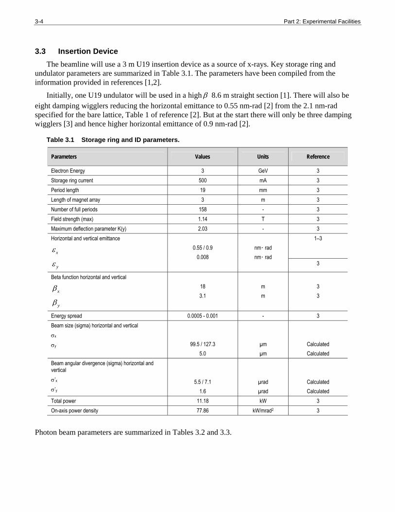
3.3 Insertion Device The beamline will use a 3 m U19 insertion device as a source of x-rays. Key storage ring and
undulator parameters are summarized in Table 3.1. The parameters have been compiled from the information provided in references [1,2].
Initially, one U19 undulator will be used in a high β 8.6 m straight section [1]. There will also be eight damping wigglers reducing the horizontal emittance to 0.55 nm-rad [2] from the 2.1 nm-rad specified for the bare lattice, Table 1 of reference [2]. But at the start there will only be three damping wigglers [3] and hence higher horizontal emittance of 0.9 nm-rad [2].
Table 3.1 Storage ring and ID parameters.
Parameters Values Units Reference
Electron Energy 3 GeV 3 Storage ring current 500 mA 3 Period length 19 mm 3 Length of magnet array 3 m 3 Number of full periods 158 - 3 Field strength (max) 1.14 T 3 Maximum deflection parameter K(y) 2.03 - 3
1–3 Horizontal and vertical emittance
xε
yε
0.55 / 0.9
0.008
nm ⋅ rad nm ⋅ rad
3
Beta function horizontal and vertical
xβ
yβ
18 3.1
m m
3 3
Energy spread 0.0005 - 0.001 - 3 Beam size (sigma) horizontal and vertical σx σy
99.5 / 127.3 5.0
µm µm
Calculated Calculated
Beam angular divergence (sigma) horizontal and vertical σ’x
σ’y
5.5 / 7.1 1.6
µrad µrad
Calculated Calculated
Total power 11.18 kW 3 On-axis power density 77.86 kW/mrad2 3
Photon beam parameters are summarized in Tables 3.2 and 3.3.

Experimental Facilities Chapter 3: CHX – Coherent Hard X-ray Beamline 3-5
NSLS-II Preliminary Design Document
Table 3.2 Source size and angular divergence. The FWHM is calculated using σ values
as 2 2ln 2FWHM σ= .
Source size, µm Angular divergence, µrad
(σ ) (FWHM) (σ ) (FWHM)
K n E, keV 'rσ ,
µrad rσ ,
µm H V H V H V H V
A. xε = 0.55 nm-rad
1.0 3 1.73 5
9.0 4.79 2.29 99.5 5.5 234.4 12.9 7.3 5.1 17.2 11.9
2.03 1 1.47 11.85 5.66 99.7 7.5 234.7 17.8 13.1 12.0 30.8 28.2
2.03 11 16.2 3.57 1.71 99.5 5.3 234.3 12.4 6.6 3.92 15.5 9.2
B. xε =0.9 nm-rad
1.0 3
1.73 5 9.0 4.79 2.29 127.3 5.5 299.8 12.9 8.6 5.1 20.2 11.9
2.03 1 1.47 11.85 5.66 127.4 7.5 300.1 17.8 13.8 12.0 32.5 28.2
2.03 11 16.2 3.57 1.71 127.3 5.3 299.8 12.4 7.9 3.9 18.7 9.2
Table 3.3 Effective beam size and angular divergence at different positions along the beamline. The FWHM is calculated using σ values as 2 2ln 2FWHM σ= .
Beam size, µm Beam angular divergence, µrad
(σ ) (FWHM) (σ ) (FWHM) Distance from sourse, m H V H V H V H V
A. xε =0.55 nm-rad
27.9 227.2 141.0 535.0 332.0 8.1 19.2
50 379.3 252.6 893.2 594.7 7.6 17.9
75 558.0 378.8 1313.9 892.0 7.4 17.5
100 738.7 505.0 1739.6 1189.3 7.4
5.1
17.4
11.9
B. xε =0.9 nm-rad
27.9 271.6 142.4 639.6 335.3 9.7 22.9
50 448.5 255.1 1056.0 600.6 9.0 21.1
75 657.4 382.5 1548.2 900.8 8.8 20.6
100 869.4 510.0 2047.2 1201 8.7
5.1
20.5
12.0

3-6 Part 2: Experimental Facilities
Figure 3.1 shows the calculated brilliance of different harmonics at values of the deflection parameter K<2.03 using the XTC program from the XOP package [4,5].
The first harmonic of the radiation is available at energies from approximately 1.47 keV to 4.5 keV, i.e., within the energy range that will not be used on the beamline. Useful undulator harmonics for the particular beamline for selecting energies from 7 to 20 keV are harmonics from 3 to 9 or possibly up to 11. The variation of K versus energy is given in Figure 3.2. Assuming the deflection parameter of the undulator, K, of any practical use will be between 2.03 and 0.4 (Figure 3.2), the maximum undulator gap will be less than 15 mm.
Data in Figure 3.1 show that different undulator harmonics should be used to keep maximum flux over the range of energies from 7 keV to 20 keV: the 3rd harmonic below approximately 8.1 keV, the 5th at 8.1 – 11.2 keV, the 7th at 11.2 – 13.7 keV, the 9th at 13.7 – 16.2 keV, and the 11th at 16.2 – 20 keV. The most important energy range of 7 – 12 keV could essentially be covered with the 3rd and 5th harmonics.
Figure 3.1 Calculated variation of the on-axis brilliance of the first few odd harmonics (from 3 to 9) of radiation from the U19 undulator versus energy at K<2.03.

Experimental Facilities Chapter 3: CHX – Coherent Hard X-ray Beamline 3-7
NSLS-II Preliminary Design Document
Figure 3.2 Calculated variation of the deflection parameter K corresponding to odd harmonics (from 3 to 9) of radiation from a U19 undulator versus energy.
Calculated heat loads for different operating modes of the U19 undulator are shown in Table 3.4. Power density distributions are shown in Figures 3.3 and 3.4. The heat load associated with a 20 µrad x 20 µrad aperture placed at 29.7 m from the source is summarized in Table 3.4.
Table 3.4 Calculated heat loads at different operating modes of the U19 undulator. The opening angle of 100 µrad (H) x 100 µrad (V) corresponds to the size of a fixed mask. The 20 (H) x 20 (V) µrad opening of the beam is the maximum required by experiments.
Distance from source, m K
FWHM of power distribution (H x
V), µrad
FWHM of flux distribution1 (H x
V), µrad Total
Power, W
Power density, W/mm2
Power through 0.1 (H) x 0.1 (V)
mrad aperture, W
Power through
0.02 (H) x 0.02 (V) mrad
apertureW
1 281 x 207 2704 47.6 343 14.8
1.73 490 x 217 20.2 x 11.9
8093 84.8 624 26.3
27.9
2.03 579 x 218 32.5 x 28.2 11143 100.1 737 31.1
Note(s): 1) See Table 3.2, B.

3-8 Part 2: Experimental Facilities
Figure 3.3 Calculated cross-section of power distribution in horizontal (FWHM=0.281 mrad) and vertical (FWHM=0.207 mrad) planes at K=1.0 and beam opening angle of 1.5 mrad (H) x 1.5 mrad.
(V).
Figure 3.4 Power density distribution versus horizontal, Phi, and vertical, Psi, opening angles at a 100 µrad (H) x 100 µrad (V) aperture at K=1.73.

Experimental Facilities Chapter 3: CHX – Coherent Hard X-ray Beamline 3-9
NSLS-II Preliminary Design Document
The results in Table 3.5 show that if only the coherent part of the beam is selected using slits, the heat at the monochromator will only be a few Watts. If, however, the 0.02 mrad x 0.02 mrad aperture is used, the heat at the monochromator will be much greater, 29 W, at a power density of about 170 W/mm2.
Table 3.5. Heat load at a 20 µrad x 20 µrad aperture placed at 29.7 m from the source. The source consists of two in-line U19 undulators tuned to the same gap. Heat load is calculated without any windows/filters or mirrors and taking into account a 200 µm thick CVD diamond filter and heat loss at a Rh-coated deflecting mirror at an incidence angle of 3 mrad.
Distance from source, m K
Power density, W/mm2
Power, W
Power, W (after 200 µm CVD diamond + mirror)
Power through central cone 'rσ , W
Power through central cone
'rσ (after 200 µm CVD diamond + mirror), W
1.0 95.1 30 9.3 1.7 0.5 29.7
1.73 169.7 53 29 3.0 1.6
3.4 Sector Layout
3.4.1 Beamline Layout Table 3.6 shows the position and size of the beamline components. Space between the main
components will be filled with vacuum bellows and pipes of suitable length. The table also shows different sections of the beamline vacuum system. The deflecting mirror and white beam slits for the inboard (CXD) beamline are indicated, but are not included in the project scope. A CAD drawing of the beamline and the end stations showing general layout of the beamline components is in Appendix B.
Table 3.6 Beamline layout.
Beamline Component Start position (mm) Length (mm) Vacuum section1 Center of Optical Element
End of shield wall 27900 Fixed mask 28200 229 0/1 28315 Differential Pump 28429 420 1 Bellow 28849 180 1 Blade BPM 29029 319 1 Bellow 29348 180 1 CVD Diamond Window / Filter 29528 303 1 29680 Bremsstrahlung collimator 29831 388 1 Bellow 30219 167 1 White beam Slit (H) 30386 229 1 Bellow 30615 167 1 White beam Slit (V) 30782 229 1 Bellow 31011 180 1 Fluorescent screen 31191 340 1 Bellow 31531 180 1 Gate valve 31711 70 1/2 1 Vacuum section is with reference to the beamline vacuum system schematic shown in Figure 3.5.
(continues)

3-10 Part 2: Experimental Facilities
Table 3.6 Beamline layout (concluded).
Beamline Component Start position (mm) Length (mm) Vacuum section1 Center of Optical Element
Outbound deflecting Mirror 31781 700 2 32131 Gate valve 32481 70 2/3 Bellow 32551 137 3 Inboard White beam Slit (H) 32688 229 3 Bellow 32917 167 3 Inboard White beam Slit (V) 33084 229 3 Bellow 33313 167 3 Pipe 33480 300 3 Gate valve 33780 70 3/4 Inboard deflecting Mirror 33850 700 4 34200 Gate valve 34550 70 4 Bellow 34620 200 4/5 Pipe 34820 800 5 Beam mask and white beam stop 35620 450 5 Bellow 36070 200 5 White Beam Shutter 36270 230 5 Bellow 36500 200 5 Hutch wall 36890 300 37040 Beam Transport pipe 36700 9145 5 Beam mask and bremsstrahlung stop 45395 450 5 Hutch wall 45250 300 45400 Bellow 45550 200 5 Gate valve 45750 70 5/16 Pipe outbound 45550 295 5 Bellow 45845 200 5 Fluorescent screen 46045 345 5 Gate valve 46390 70 5/6 DCM and pink beam stop 46460 745 6 46832.5 Gate valve 47205 70 6/7 Bellow 47275 200 7 Pink Beam Shutter 47475 230 7 Pipe 47705 604 7 Hutch wall 48100 300 Fluorescent screen 48309 340 7 Quadrant BPM 48649 35 7 Bellow 48684 150 7 Pink beam Guard slits 48834 65 7 Gate valve 48899 70 7/8 VFM 48969 700 8 49319 Gate valve 49669 70 8/9 Pipe 49739 290 9 Pink beam Slits 50029 65 9 SiN / CVD Diamond Window 50094 20 / 303 9 Pink beam/bremsstrahlung stop TBD 400 14 End station 1 equipment TBD Hutch wall 60000 300

Experimental Facilities Chapter 3: CHX – Coherent Hard X-ray Beamline 3-11
NSLS-II Preliminary Design Document
3.4.1.1 Beamline Vacuum System
A schematic of the beamline vacuum system is shown in Figure 3.5.
Figure 3.5 Beamline vacuum system schematic.

3-12 Part 2: Experimental Facilities
3.4.1.2 Data Acquisition System and Motion Control
The 8-axis motion control boxes having RS232, USB, and Ethernet interfaces are customized to suit the beamline motorised axis. They also have built in micro IOCs.
Separate micro IOCs control vacuum pump controllers, vacuum gauge controllers, DPT controllers, current amplifiers, and CCD cameras.
The EPS PLC has analogue input and digital input and output. It is linked to solenoid valve actuators, fluorescent screen actuators limits, thermocouples, water flow meters, vacuum interlocks, vacuum gauge controllers, cooling water flow meters in the heat exchangers, thermocouples in the heat exchangers, and water conductivity probes.
The PSS shutter is controlled from the PSS and sends and receives status signals to/from EPS PLC.
The vacuum schematic is shown in Figure 3.5. Vacuum gauge controllers are monitoring vacuum level measured by Pirani and ion gauges mounted on different beamline components. Ion pump controllers provide power to each of the ion pumps used on the beamline. High voltage splitter units are used where necessary to power more than one pump per output channel.
Micro IOC controlling the vacuum system uses RS485 protocol for communication with the pump and gauge controllers. Vacuum gauge controllers are integrated with the EPS system to monitor vacuum level in different sections of the beamline.
Piezo actuators need to have vacuum interlocks linked to the vacuum gauge controllers.
A schematic of the beamline controls is shown in Table 3.7.

Experimental Facilities Chapter 3: Coherent Hard X-Ray Beamline 3-13
NSLS-II Preliminary Design Document
Table 3.7 Controls schematic of the CHX beamline.
Number of elements per unit
Controlled by 8-axis motion control units Controlled by EPS PLC Controlled by micro IOC PC
Beamline Component No. of units
Stepper/ Pico Motor
Server Motor
Limit/ datum switch Encoder
Reference point
Flow meter
Thermo-couple
Solenoid valve
actuator CCD
camera
DPT control
unit Current amplifier
Beamline control system 1 1
Fixed mask 1 1 1 Blade BPM 1 2 4 1 1 CVD Diamond windows 1 1 1 Bremsstrahlung collimator
2 1 1
Slits (H or V) 12 1 2 1 Gate Valve 14 2 1 Horizontally Deflecting Mirror (water cooled)
2 6 10 5 5 1 1
VFM 2 5 10 5 5 1 HFM 1 5 10 5 5 1 Pink Beam shutter 3 4 1 1 1 Fluorescent screen 5 2 1 1 1 DCM (water cooled) 2 5 1 8 7 6 1 3 1 White/pink beam stops 5 1 1 QBPM 2 1 2 1 Water cooled windows (diamond or Be)
2 1 1

3-14 Part 2: Experimental Facilities
3.4.2 Beamline Components
3.4.2.1 High Heat Load Monochromator
A water cooled Si(111) DCM with no sagittal focusing on the second crystal should provide energy resolution of ~10-4, fixed exit beam height and operate across the requested energy range from 7 keV to 20 keV. Expected performance parameters of the DCM and some useful information are given in Table 3.8. We also assume 25 mm vertical offset between the incoming and outgoing beams and that the beam ‘walk’ alone the second crystal as the energy changes will be taken by longitudinal translation of the crystal. The results in Table 3.8 show that:
The energy resolution is expected to be from 1.34 410−⋅ to 1.42 410−⋅ .
The Bragg angles are from 5.67o to 16.4o. The Bragg angle calculation assumes the lattice constant of Si(111) of 5.4309 Å.
Perpendicular translation of the 2nd crystal over the energy range is about 0.44 mm.
Longitudinal translation of the 2nd crystal over the energy range is approximately 82 mm.
The footprint of the beam at the crystals of the Si(111) monochromator at all energies is less than 0.22 mm x 2.2 mm, assuming 4.8 µrad (H) x 4.8 µrad (V) opening of the beam (coherent beam).If the aperture is 20 µrad (H) x 20 µrad (V), the maximum beam footprint increases to 0.9 mm x 9 mm.
The design of the DCM should meet stability requirements and be able to withstand heat loads, as discussed earlier.
Table 3.8 Performance parameters of the Si(111) DCM.
Energy, keV Parameters
7 12 20 Wavelength, Å 1.7712 1.0332 0.6199
Bragg angle Bθ , deg 16.4058 9.483 5.6732
Reflectivity (double reflection) 0.85 0.94 0.98 Energy resolution Rocking (Darwin) width1, µrad 39.1586 22.2161 13.2122 Bandpass due to source size 4.3 1010−⋅ 7.1 1010−⋅ 1.2 910−⋅
Bandpass due to accepted angular divergence 1.6 510−⋅ 2.9 510−⋅ 4.8 510−⋅
Resolution of the DCM 1.34 410−⋅ 1.36 410−⋅ 1.42 410−⋅
Resolving power2 7463 7349 7067 Crystal size and position Vertical offset between incoming and outgoing beams, D, mm 25 Perpendicular offset between 1st and 2nd crystals3, mm 13.0 12.7 12.6 Longitudinal offset between the crystals4, mm 44.3 75.9 126.4 Maximum beam footprint5
transverse to the beam, mm along the beam, mm
0.22
2.21
See table notes on next page.

Experimental Facilities Chapter 3: CHX – Coherent Hard X-ray Beamline 3-15
NSLS-II Preliminary Design Document
Notes for Table 3.8:
1) Intrinsic resolution of Si(111) is .cryst
δλλ
⎛ ⎞⎜ ⎟⎝ ⎠
= 1.33 ⋅ 10-4. The rocking (Darwin) width is tan Bδλ θλ
Ω = .
2) The resolution is determined by the width of the rocking curve of the crystal, beam opening angle and size of the source
22 2 2
.
( )cotsource slit Bcryst
EE
δλθ θ θλ
Δ ⎛ ⎞= Δ + Δ + ⎜ ⎟⎝ ⎠
,
/source y pθ σΔ = and 'min( , ) /slit y vs pθ σΔ = ,
where yσ is the vertical source size (FWHM), 'yσ is the vertical divergence of the beam (6σ ), vs is the opening of the
monochromator vertical entrance slit and p is a distance from the source.
Resolving power of the monochromator is reverse to the total band pass, i.e., it is EEΔ
.
3) The distance, X, measured perpendicular to the optical surfaces of the crystals: 2sin B
DXθ
=, where D is the constant vertical offset
between incoming and outgoing beams.
4) The distance, Y, measured along the surface of the crystals: 2cosDYθ
=, where D is the constant vertical offset between incoming
and outgoing beams. The longitudinal offset shows beam walk parallel to the surface of the crystals as the Bragg angle changes.
To maintain the constant beam offset, D, the X and Y should satisfy the condition 2 2 2
1 1 4X Y D
+ =.
5) The beam footprint depends on the rms size and divergence of the incoming beam, DCM distance from the source and the Bragg angle so that
2 ' 2, ,( ) ; ; / sinx y x y x yF p F F F Fσ σ θ= + ⋅ = = ,
where ,x yσand
',x yσ
are the size and divergence of the source, correspondingly, p is the distance from the source and θ is the Bragg angle.
3.4.2.2 Mirrors (White Beam and Monochromatic)
As has been discussed earlier, the beamline is expected to have mirrors for collimating and focusing the beam in horizontal and vertical planes. Preliminary analysis shows that the full energy range of 7 – 20 keV can be covered without changing the angle of incidence while providing good transmission of the x-ray beam over the whole range.
Increase of the angle of incidence is favourable for reducing the cut-off energy, lengths of the mirrors, and for improving harmonic rejection, but the reflectivity of the mirrors decreases. We have considered using bare Si, Pt, Pd, and Rh coatings and concluded that Rh and bare Si are most suitable for the required energy range. Pd is very similar to Rh, but the latter has slightly better reflectivity. Reflectivity of Pt shows a few absorption edges and it is more suitable for higher energies.
Most mirror suppliers will guarantee densities of Rh in the coatings to be better than 90% of the bulk material, which is 12.41 g/cm3
[6,7]. For calculating reflectivity of the mirror stripes, we therefore assume in this analysis a density for Rh of 11.17 g/cm3. The densities are usually lower, about 85% of the bulk, for bimorph mirrors. The lower density means slightly lower reflectivity and

3-16 Part 2: Experimental Facilities
lower cut-off energies at similar incidence angles. As the density of Rhodium decreases from 90% to 85%, the cut-off energy decreases by about 550 eV.
The density of Si, 2.33 g/cm3 [7], is slightly higher than the density of silica, 2.2 g/cm3 [7]. Usually silica is used as a substrate for making mirrors to focus monochromated beam and silicon is used to make mirrors operating in a white beam. The data in Figure 3.6 show that replacing silica with silicon as a mirror substrate increases the cut-off energy by approximately 300 eV.
Figure 3.6 shows variation of the critical angle of the mirrors versus energy for Si, silica, Rh (and Pt). The critical angles were calculated as 2cα δ= , where δ is a real part of the refractive index of material. Incidence angle of the mirrors should ensure that the low energy beam is not contaminated by the beam of higher energy. Also it is desirable to keep the mirrors reasonably short. But the reflectivity of the mirrors decreases as the angle of incidence increases. Therefore the incidence angle should be optimized taking into account these factors and ease of use.
The useful energy range is defined from 7 keV to 20 keV [3]. From the point of view of ease of use, changing the mirror incidence angle should be avoided. In that case the mirrors could be set at an incidence angle of approximately 3.0 mrad to achieve about 95% reflectivity using a Rh stripe. Higher reflectivity can be obtained using Si or silica stripe (Figure 3.7).
We therefore suggest operating at a fixed angle of incidence and using bare Si (cut-off energy 10.4 keV) below approximately 10 keV, and Rh (cut-off energy 20.8 keV) from 10 keV to 20 keV. The reflectivity of Si and Rh at 3 mrad is shown in Figure 3.8. We suggest using silica rather than silicon with a monochromated beam.

Experimental Facilities Chapter 3: CHX – Coherent Hard X-ray Beamline 3-17
NSLS-II Preliminary Design Document
Figure 3.6 Variation of the critical thickness versus energy for bare silica, silicon, rhodium, and platinum. The double lines for Rh and Pt correspond to different densities of the materials: 85% density of the bulk for the lower line and 90% for the upper line.
2 3 4 5 6 7 8 9 10 110.65
0.7
0.75
0.8
0.85
0.9
0.95
1
Angle of incidence, mrad
Max
imum
ref
lect
ivity
Si
Rh
Figure 3.7 Variation of maximum reflectivity of Rh and Si versus angle of incidence.

3-18 Part 2: Experimental Facilities
Figure 3.8 Reflectivity of silicon (top) and rhodium at 90% density of bulk (bottom), at 3.0 mrad.
Some useful characteristics of the mirrors are shown in Table 3.9. The lengths of the mirrors are calculated for the case of 0.02 mrad x 0.02 mrad opening of the beam and for beam divergence of the central cone.

Experimental Facilities Chapter 3: CHX – Coherent Hard X-ray Beamline 3-19
NSLS-II Preliminary Design Document
Table 3.7 Parameters of the mirrors. The p and q are source-to-mirror and mirror-to-image distances. Mirror HDM2 is for the inboard beamline and not in the project scope.
Beam Footprint, mm
Mirror
Optical distance
from source, M
Incidence angle, mrad Coating
Aperture 20 x 20 µrad
Aperture 4.8 x 4.8 µrad
Bent radius, m P, m Q, m
HDM1 26.89 3 Si, Rh 179 43 N/A -∞ ∞ HDM2 28.96 3 Si, Rh 193 46 N/A -∞ ∞ VFM 47.13 3 Silica, Rh 314 75 TBD -∞ TBD
3.4.3 FEA and Ray Tracing Analysis The calculations are based on the assumptions that the horizontally deflecting mirror (HDM) at
an incidence angle of 3 mrad uses a bare silicon reflecting surface and is located at 32.13 m from the source. The beam opening aperture is 0.020 mrad x 0.020 mrad. The Si(111) DCM after the deflecting mirror is at 46.83 m from the source. The primary beam is attenuated by the 200 µm thick CVD diamond window/filter located upstream of the mirror. The horizontally deflecting mirror selects 0.02 mrad of the beam to the side from the center.
The results of the ray tracing using XOP and Shadow packages are given in Tables 3.10 and 3.11. To compensate for defocusing of the beam by slope errors at the HDM and DCM, the bend radius of the HDM was optimized to achieve a single spot and maximize the intensity. Only for Case 1 in Tables 3.10 and 3.11, representing the worse case of heat load and thermal slope errors, the optimum radius was smaller than the nominal radius.
Table 3.10 Results of FEA analysis at different heat loads at the horizontally deflecting bare Silicon mirror (at 32.13 m, incidence angle 3 mrad) and 1st crystal of the Si(111) DCM (at 46.83 m, Bragg angle of 12.69 corresponding to 9 keV). Beam opening aperture is 0.02 mrad x 0.02 mrad. The 200 µm thick CVD diamond window is assumed upstream of the mirror. Single or double U19 undulator source is operating in high-beta straight and in low emittance (0.55 nm-rad) mode.
Max slope (µrad) RMS slope (µrad) Beamline Component
Final Case No. Source X Y X Y
1 2xU19, K=1.731, Power= 20.5 W 2.63 0.94 1.15 0.78
2 1xU19, K=1.0, Power= 2.1 W 0.27 0.09 0.12 0.08
3 1xU19, K=1.731, Power= 10.0 W 1.28 0.45 0.56 0.38
Horizontally deflecting mirror
4 2xU19, K=1.0, Power= 4.2 W 0.53 0.19 0.23 0.16
1 2xU19, K=1.731, Power= 11.7 W 16.6 22.1 7.6 7.8
2 1xU19, K=1.0, Power= 3.0 W 4.1 5.4 1.9 1.9
3 1xU19, K=1.731, Power= 5.7 W 7.9 10.4 3.6 3.7 DCM
4 2xU19, K=1.0, Power= 6 W 8.3 11.0 3.8 3.9

3-20 Part 2: Experimental Facilities
Table 3.11 Results of ray tracing analysis (final) of the hard coherent beamline at 9 keV. Flux was calculated over the 1000 µm x 20 µm aperture placed at the sample position at 50 m from the source. The primary beam, Io, is assumed to be of 0.020 mrad x 0.020 mrad. The mirror is 250 mm (L) x 50 mm (W). Bending radius of the VFM was optimized by changing the focal distance. Nominal radius before any optimization is 447.2 m.
Spot size, µm Flux, ph/s Spot size, µm Flux, ph/s Optimized Rm (VFM), m
Case No.
Incoming Flux Io , ph/s
No crystal distortion Slope errors at HDM and DCM
1 5.39 x 10¹⁴ 314 x 4.7 5.52 x 10¹³ 287 x 1.8 1.41 x 10¹³ 264.5
2 1.28 x 10¹⁴ 321 x 4.7 1.29 x 10¹³ 291 x 1.7 6.58 x 10¹² 492.5
3 2.18 x 10¹⁴ 329 x 5.3 2.19 x 10¹³ 307 x 2.6 7.37 x 10¹² 812.7
4 2.93 x 10¹⁴ 300 x 3.7 2.96 x 10¹³ 272 x 2.8 1.24 x 10¹³ 876.0
3.4.4 Instruments
The source brightness at NSLS-II will enable XPCS experiments to study dynamics in disordered systems at time scales well below milliseconds. The goal of the instrumentation in the experimental endstation (Figure 3.9) is to turn this potential into reality. To do so, the instrumentation must not compromise the superior coherence quality of the source; a state-of-the-art detector is needed to actually measure the intensity fluctuations in x-ray speckles that correspond to sample dynamics. Detailed requirements have already been set forth in the CDR and will not be repeated here. This document will only describe the actual instrumentation that will satisfy these requirements.
Figure 3.9 Experimental endstation.
The first component inside the endstation is a vertical focusing mirror that will reduce the vertical coherence length to match that in the horizontal direction. The mirror is followed by three sets of slits to select coherent flux and clean up parasitic scattering from the slits. Between the mirror and slits are an attenuator and a fast shutter. The attenuator is necessary for samples that produce strong scattering. The x-ray absorbing material in the attenuator will be double-side polished silicon so that it will not introduce significant phase error to the propagating x-ray wave front. The shutter is necessary when a CCD-type detector is being used and to avoid sample exposure to x-rays and radiation damage when data are not being collected.

Experimental Facilities Chapter 3: CHX – Coherent Hard X-ray Beamline 3-21
NSLS-II Preliminary Design Document
The sample will be housed in a vacuum sample chamber just downstream of the third set of slits. For solid samples, a hexapod will be used to position the sample into the beam and translate the sample before the exposed part is damaged by x-rays. The advantage of the hexapod is that an arbitrary point on the sample can be programmed as the rotation center. This is particularly useful for thin film samples that are measured in grazing incidence geometry. A rotary stage under the hexapod makes up for the hexapod’s limited azimuthal rotation range. Liquid samples will be continuously flowed through a flow cell to reduce radiation damage.
The length of the flight path downstream of the sample chamber will be 10 m long to produce x-ray speckles comparable to the pixels (assuming 100 µm) in size. It is made up of several sections so that a shorter sample-to-detector distance is possible, if desired. Because of the long length of the flight path, it also needs to be large enough in diameter in order to capture enough q-range. With the current design of 20-in. tube, the highest q accessible at 12 keV and 10 m sample-to-detector distance is ~0.15 Å-1. The flight tube can be offset so that the beam is not centered on the exit window and higher q-range can be accessed on one side. The tube size is most likely larger that that of the detector itself. The detector will therefore be mounted on an x–z stage so that multiple images can be collected and tiled to cover the entire available q-range.
A beamstop assembly is located at the end of the flight path. This assembly consists of x–z-rotary stages that can position multiple beamstops (e.g., with different size or beam intensity detectors) into the beam to block the direct beam and measure its intensity. A similar assembly is currently being built at beamline X9 of NSLS.
The detector group at NSLS is planning to develop a pixel array detector with a built-in auto-correlator for each pixel. Such a detector will be ideal to realize the full potential of XPCS measurements at NSLS-II. In case that the development of such a detector is not successful, a pixel array detector without auto-correlators will be used instead. Specifically, a pixel array detector with 75 µm pixels and 10 kHz frame rate is being designed by DECTRIS, which is currently marketing its 170 µm, 200 Hz frame rate pixel array detector, PILATUS. In this case, a large computing facility must be established to store and post-process collected data.
3.5 Preliminary Safety Analysis
Information about the shielding design, personnel safety system, and equipment protection system is provided elsewhere in the PDR.
3.6 Additional Requirements Imposed on the Conventional Facilities
Special attention must be given to stability requirements. These are determined by temperature stability and vibration (natural and self-inflicting) and they were extensively discussed at the NSLS-II Stability Workshop in April 2007 [8-10].
The beam stability requirements for different components are based on achieving less than 10% variation of the beam size. To conduct different experiments like the ones mentioned by Sandy [8] or Shen [9], horizontal and vertical position stability should be 0.2 µm, vertical angle stability 0.2 µrad, and horizontal angle stability 1 µrad [10]. For SAXS, high beam intensity stability (<1%) is desirable.
Typical temperature variations measured at ESRF are about ±0.5o over 24 hours [11]. At the ID22 beamline at ESRF, temperature variations are < ±0.1o over 24 hours [11]. Similar or better stability should be achieved for the NSLS-II beamline, especially taking into consideration its

3-22 Part 2: Experimental Facilities
extreme length. For demanding beamlines, new high-flow-rate air conditioning units (air renewal rate 20 cycles/hour) are used. Vibrations from air flow are reduced using porous ducts [11].
Measures to reduce thermal effects include choosing low-expansion materials, cooling local heat sources, thermally insulating vessels, moving all control electronics outside the hutches [11], using thermally insulated sand-filled stands, ensuring that the first natural frequency is above 50 Hz [12], and ensuring high thermal inertia [11]. It has been pointed out that angular vibration drifts are much worse than linear [11]. This is particularly true for long beamlines like IXS.
Temperature control requires high-resolution industrial grade instruments and controls with excellent repeatability. For example, narrow span thermistor/transmitters with 0.01o C sensitivity and programmable controllers with 14-bit resolution will be used [13].
Vibrations generated by water chillers, fans, compressors, etc. can be reduced by selecting rotating equipment with stringent balance specifications, using spring support for rotating equipment and inertial bases [14].

Experimental Facilities Chapter 4: Coherent Hard X-Ray Beamline 3-23
NSLS-II Preliminary Design Document
References
1. NSLS-II Conceptual Design Report, Brookhaven National Laboratory (2006). http://www.bnl.gov/nsls2/project/CDR/
2. Summary of NSLS-II Source Properties, NSLS-II User Workshop 17-18 July 2007, http://www.bnl.gov/nsls2/project/source_properties.asp, 31 July 2007 (2007).
3. BNL staff, Private communications (2007).
4. M.S. del Rio, R. J. Dejus, XOP Home Page: http://www.esrf.fr/computing/scientific/xop2.1/
5. M.S. del Rio, SPIE Proc. 3448, 230 (1998).
6. X-Ray Mass Attenuation Coefficients, NIST, http://physics.nist.gov/PhysRefData/ XrayMassCoef/tab1.html
7. Densities (g/cm3) of some Common Materials, LBL, http://henke.lbl.gov/cgi-bin/density.pl
8. A. Sandy, A hard X-ray Coherent scattering beamline for NSLS-II and …SAXS?, NSLS-II User Workshop, 17-18 July 2007, http://www.bnl.gov/nsls2/workshops/docs/UserWorkshop/ BOS/coherent/Shen_Soft_Coherent.ppt (2007).
9. Q. Shen, Overview on Coherent Diffraction Imaging and Its Applications, NSLS-II User Workshop, 17-18 July 2007, http://www.bnl.gov/nsls2/workshops/docs/UserWorkshop/ BOS/coherent/Shen_Soft_Coherent.ppt (2007).
10. Stability Requirements for NSLS-II Beamlines, Report of the NSLS-II Stability Task Force, NSLS-II Stability Workshop, April 18-20, 2007, http://www.bnl.gov/nsls2/workshops/docs/Stability/closeout/Z_StabilityReport.pdf
11. Y. Dabin, Stability of instruments at ESRF, NSLS-II Stability Workshop, April 18-20, 2007, http://www.bnl.gov/nsls2/workshops/docs/Stability/Dabin_ESRF_Stability.ppt
12. S. Sharma and V. Ravindranath, Stability of Mechanical Systems, NSLS-II Stability Workshop, April 18-20, 2007, http://www.bnl.gov/nsls2/workshops/docs/Stability/ Sharma_mechanicalSystems.ppt
13. C. Channing, Conventional Facilities. Temperature Stability, NSLS-II Stability Workshop, April 18-20, 2007, http://www.bnl.gov/nsls2/workshops/docs/Stability/Channing_CF_ Tempstablity.ppt
14. J. Sidarous, Engineering Approaches to Reducing Floor Vibration at the APS and CNM, NSLS-II Stability Workshop, April 18-20, 2007, http://www.bnl.gov/nsls2/workshops/ docs/Stability/Sidarous_CF.ppt

3-24 Part 2: Experimental Facilities
Appendix A: Ray Diagram
Figure 3A.1 Bremsstrahlung and photon beam ray tracing drawing for XPCS beamline.
Experimental Facilities Chapter 3: CHX – Coherent Hard X-ray Beamline 3-25
NSLS-II Preliminary Design Document
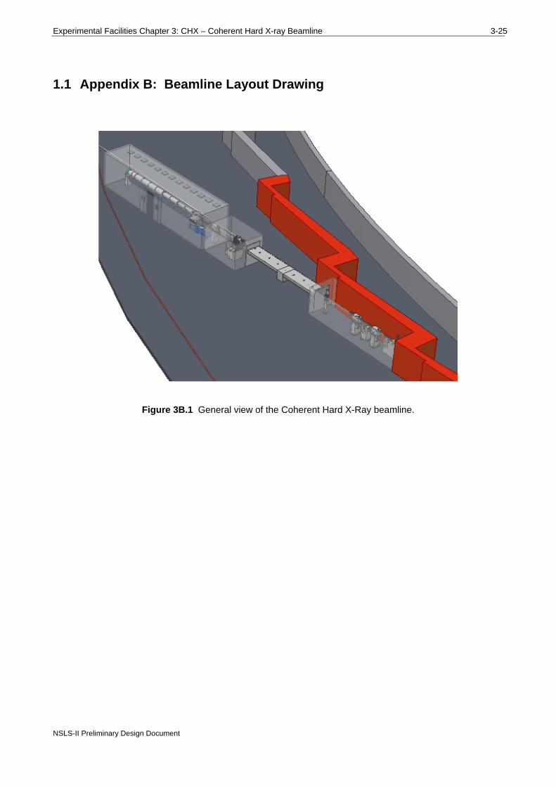
1.1 Appendix B: Beamline Layout Drawing
Figure 3B.1 General view of the Coherent Hard X-Ray beamline.

3-26 Part 2: Experimental Facilities
1.2 Appendix C: List of Key Beamline Components
CVD Diamond Windows
Chemical Vapour Deposition (CVD) Diamond offer extreme hardness, high thermal conductivity, chemical inertness, and high transparency over a very wide spectral range. Stronger and stiffer than Beryllium, with lower thermal expansion and lower toxicity, it is ideal for UHV isolation windows in X-ray beamlines. Windows can be supplied embedded in UHV flanges and with efficient water cooling. CVD Diamond windows, Figure 3C.1, developed in cooperation with the Fraunhofer Institute of Germany and Paul Scherrer Institute of Switzerland, with the support of Argonne National Laboratory in the USA, are manufactured by Diamond Materials GmbH.
Specifications
Thickness: 200 µm Diameter: 5 – 50mm Vacuum performance: <10-9mbar l/sec Surface finish: 10nm RMS roughness The window will be used when a monochromatic beam mode is replaced with the pink beam regime. The window will be put in place of SiN windows that are used in a monochromatic mode as last windows before the sample.
Figure 3C.1 Water cooled CVD Diamond window.

Experimental Facilities Chapter 3: CHX – Coherent Hard X-ray Beamline 3-27
NSLS-II Preliminary Design Document
Fixed Mask and CVD Diamond Window / Filter
Figure 3C.2 Outline specification and schematic drawing of a typical diamond window.
Blade BPM The White Beam (BBPM) consists of a vacuum vessel containing the sensor mechanism, a
support stand, and associated electronics.
The sensor mechanism consists of 2 insulated blades fixed a known distance apart in a vacuum chamber. The signals from these electrodes provide a measurement of the position of the beam.
The gap between the blades and their orientation are chosen to provide a usable current without significant disturbance to the usable x-ray beam.
Quadrant BPM The QBPMs are available in HV and UHV configurations. The QBPMs will need to be taken
out of the beam when the end station is used in a pink beam regime.
Fluorescent Screens The screens are made in two modifications: water cooled and not water cooled. For using with
pink beam water cooled option should be chosen.

3-28 Part 2: Experimental Facilities
High Heat Load Slits for Undulator Beams
The slit system, Figure 3C.3, consists of two L-shaped absorbers arranged in series along the beam (the downstream being rotated through 180°) to define the aperture, Figure 3C.4. Each mask therefore defines two edges of the beam. Each absorber is moved laterally and vertically by external translation stages to define the beam. There are edge-welded bellows before, between and after the two absorbers, which allow the movement of the slits relative to the beam. The slit mechanism is mounted on a synthetic granite-filled mild steel frame for stability and vibration rejection. Slits of this type will be used to define the size of the white beam.
Figure 3C.3 High heat load slits.
Figure 3C.4 High heat load slits schematic.

Experimental Facilities Chapter 3: CHX – Coherent Hard X-ray Beamline 3-29
NSLS-II Preliminary Design Document
Pink Beam Slits The cooled Slit Unit comprises two independently actuated slit blades, mounted on the same
flange. Each Slit System has a horizontal slit unit and a vertical slit unit, each of which is mounted on a flange on a vacuum vessel, one on top of the vessel and one at the side of the vessel. Each pair of blades defines either the horizontal or vertical dimension of the beam, Figure 3C.5.
Figure 3C.5 Schematic set-up of a horizontal/vertical slit system.
Each cooled slit unit consists of two slit blades, each of which is mounted onto a water-cooled Glidcop body and connected to an external actuator mechanism through a flange on the slit vessel. Indium foil is clamped between the slit blade and the copper body to enhance heat transfer by conduction, Figure 3C.6. On each slit blade the edge nearest the beam is chamfered, at 3°, to produce a sharp defining (knife) edge. The chamfered face is positioned on the downstream side of the blade (on the side of the blade furthest from the source). On each cooling block the edge nearest the beam is chamfered, Figure 3C.7, to reduce the power density of the beam on the block at the operating condition. The chamfered face is positioned on the upstream side of the block. An additional tungsten disaster plate is added to prevent damage over the full range of operation. The slit blades are manufactured from 5 mm thick tungsten alloy. The blade defining edge protrudes 0.5 mm above the cooling block.
The slits are specially designed for high heat loads where conventional water cooled slits cannot be used.
Incident SR Beam
Vertical set of blades
Horizontal set of blades
Opening aperture

3-30 Part 2: Experimental Facilities
Figure 3C.6 Cooling block and slit blade arrangement.
44.4
10.0
40.5
3°
11°
24°
35°
0.5
30°
Figure 3C.7 Schematic of the cooling block and slit blade.
Blade
Glidcop Cooling Block
Beam
Ø6 mm Cooling
Tube
Tungsten Disaster Plate

Experimental Facilities Chapter 3: CHX – Coherent Hard X-ray Beamline 3-31
NSLS-II Preliminary Design Document
Conventional Water Cooled Slits Each cooled slit unit consists of two slit blades, each of which is mounted onto a water-cooled
OFHC copper body and connected to an external actuator mechanism through a flange on the slit vessel. Indium foil is clamped between the slit blade and the copper body to enhance heat transfer by conduction, Figure 3C.8. On each slit blade the edge nearest the beam is chamfered, at 3°, to produce a sharp defining (knife) edge. The chamfered face is positioned on the downstream side of the blade (on the side of the blade furthest from the source). On each cooling block the edge nearest the beam is chamfered, at 20°, to reduce the power density of the beam on the block. The chamfered face is positioned on the upstream side of the block. The slit blades are manufactured from 10 mm thick tungsten alloy (95% tungsten or more with the remainder of nickel and iron). The blade defining edge protrudes 0.2 mm above the cooling block.
Figure 3C.8 Cooling block and slit blade arrangement.
For the cooled slits, a spare port is provided on the vessel. This port can accommodate an electrical feedthrough thus allowing thermocouples to be fitted to the slit blades should this be required. Thermocouples are not fitted as standard but can be retrofitted as an upgrade.
Bremsstrahlung Collimator and Beam Stops The bremsstrahlung collimators are typically made of 300 mm of lead and their dimensions are
calculated from the ray tracing. We will use one of the collimators immediately after the CVD Diamond window/filter.
The first bremsstrahlung stop will be specially designed to be put at the downstream end of the long beam transport pipe entering the outbound beamline. This is done to ensure sufficient separation of the beam deflected by the mirrors. The bremsstrahlung stop will be assembled with the water cooled beam mask.
As the end stations are designed for the pink beam bremsstrahlung stops are needed after the sample positions. Exact location is to be decided when the end stations are designed.
Blade
Cooling Block
Beam
Ø6 mm Cooling
Tube

3-32 Part 2: Experimental Facilities
Brehmsstrahlung stops are also anticipated after the DCMs. Depending on the detailed design they will be made of lead (out of vacuum) or Tungsten (in vacuum). The beam stops will need to be translated up and down when the operating mode is changed from monochromatic to pink beam mode.
Mirrors Parameters of the mirrors that will be used on the beamline are given in Table 3.9. It is not
immediately clear whether bimorph mirror will offer any significant advantage. Adaptive optics for VFM mirror can be particularly useful if a water cooled DCM is used because residual slope errors could be compensated.
Plane deflecting mirrors will be water cooled and specially designed to cut out part (about one-half) of the whole beam. They will operate at a fixed angle of incidence to simplify operation of the beamline. The deflecting mirrors will be made of silicon, whereas the other mirrors can use silica as a cheaper alternative.
The downstream vertical focusing mirror will operate in the monochromatic beam only. The mirror system will have capability of removing the optics from the beam to allow operating in pink beam regime.
Quality of the optical surface that can be achieved is being continuously improved by makers of the mirrors.
Double Crystal Monochromators The water-cooled monochromator system will most likely use a vertical beam offset of about 25
mm and a long second crystal to eliminate longitudinal translation and improve stability. The second crystal will be translated vertically to keep fixed offset of the beam.
The DCM is designed to operate at energies of 5 – 20 keV, has a fixed offset of 25 mm and uses a set of Si(111) crystals. The DCM is designed to achieve angular beam stability of 200 nrad that should be adequate for the current application.
Some useful characteristics of the monochromator of that type are shown in Table 3.8.
White and Pink Beam Shutters Pink beam shutters will also be used. They will be positioned after the DCMs and before the
hutch wall. Essentially pink shutters are made of a 15 mm thick water cooled copper plate clamped to a 35 mm thick tungsten block.
SiN 200 nm Window
Supplier SPI Supplies
Outside frame dimensions 7.5 mm x 7.5 mm
Window size 1.5 mm x 1.5 mm
Membrane thickness 200 nm
Frame thickness 200 µm
Quantity Pack of 50