308288s plural component mix manifold - graco inc. wear the appropriate protective clothing, gloves,...
TRANSCRIPT
Instructions -- Parts List
GRACO INC. P.O. BOX 1441 MINNEAPOLIS, MN 55440--1441Copyright 1993, Graco Inc. is registered to I.S. EN ISO 9001
Plural ComponentMix Manifold
For Proportional Mixing of Plural Component Coatings.
308288S
Model 239732
Model 243487Model 243486
Model 236931
7384B
01909C
TI0173
TI0224
Important Safety InstructionsRead all warnings and instructions in this manual.Save these instructions.
See page 2 for model numbers and maximum working pressures.
2 308288
Model DescriptionModel No. Description Working Pressures236931 Mix Manifold 3000 psi (21 MPa, 207 bar) Maximum Working Pressure
100 psi (0.7 MPa, 7 bar) Maximum Air Input Pressure
239732 Mix Manifold 3000 psi (21 MPa, 207 bar) Maximum Fluid Working Pressure4000 psi (28 MPa, 276 bar) Maximum Fluid Working Pressurewith Part No. 239954 High Pressure Spring Kit
100 psi (0.7 MPa, 7 bar) Maximum Air Input Pressure
243486 Mix Manifold for First Stage of3K system
3000 psi (21 MPa, 207 bar) Maximum Fluid Working Pressure100 psi (0.7 MPa, 7 bar) Maximum Air Input Pressure
243487 Mix Manifold for Second Stageof 3K system
3000 psi (21 MPa, 207 bar) Maximum Fluid Working Pressure100 psi (0.7 MPa, 7 bar) Maximum Air Input Pressure
Table of ContentsWarnings 3. . . . . . . . . . . . . . . . . . . . . . . . . . . . . . . . . . . . . .How the 2K Mix Manifold Works 5. . . . . . . . . . . . . . . . . .How the 3K Mix Manifold Works 8. . . . . . . . . . . . . . . . . .Installation 12. . . . . . . . . . . . . . . . . . . . . . . . . . . . . . . . . . . .Operation 17. . . . . . . . . . . . . . . . . . . . . . . . . . . . . . . . . . . .Maintenance 20. . . . . . . . . . . . . . . . . . . . . . . . . . . . . . . . . .Troubleshooting 21. . . . . . . . . . . . . . . . . . . . . . . . . . . . . . .Service 22. . . . . . . . . . . . . . . . . . . . . . . . . . . . . . . . . . . . . .
Parts Drawings and ListsPurge Valves 27. . . . . . . . . . . . . . . . . . . . . . . . . . . . . .Dispense Valves 28. . . . . . . . . . . . . . . . . . . . . . . . . . .Manifold 30. . . . . . . . . . . . . . . . . . . . . . . . . . . . . . . . . .
Accessories 34. . . . . . . . . . . . . . . . . . . . . . . . . . . . . . . . . .Technical Data 36. . . . . . . . . . . . . . . . . . . . . . . . . . . . . . . .Dimensions 36. . . . . . . . . . . . . . . . . . . . . . . . . . . . . . . . . . .Warranty 40. . . . . . . . . . . . . . . . . . . . . . . . . . . . . . . . . . . . .Graco Information 40. . . . . . . . . . . . . . . . . . . . . . . . . . . . .
SymbolsWarning Symbol
WARNINGThis symbol alerts you to the possibility of seriousinjury or death if you do not follow the instructions.
Caution Symbol
CAUTIONThis symbol alerts you to the possibility of damage toor destruction of equipment if you do not follow theinstructions.
308288 3
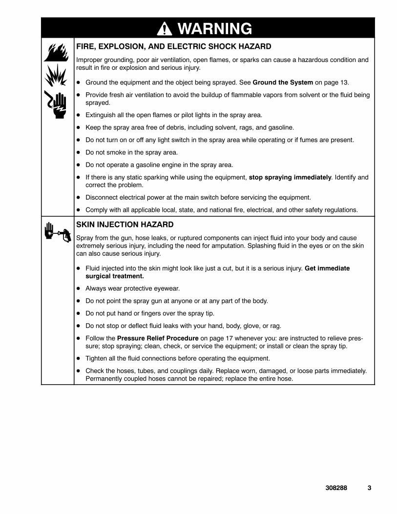
WARNINGFIRE, EXPLOSION, AND ELECTRIC SHOCK HAZARD
Improper grounding, poor air ventilation, open flames, or sparks can cause a hazardous condition andresult in fire or explosion and serious injury.
D Ground the equipment and the object being sprayed. See Ground the System on page 13.
D Provide fresh air ventilation to avoid the buildup of flammable vapors from solvent or the fluid beingsprayed.
D Extinguish all the open flames or pilot lights in the spray area.
D Keep the spray area free of debris, including solvent, rags, and gasoline.
D Do not turn on or off any light switch in the spray area while operating or if fumes are present.
D Do not smoke in the spray area.
D Do not operate a gasoline engine in the spray area.
D If there is any static sparking while using the equipment, stop spraying immediately. Identify andcorrect the problem.
D Disconnect electrical power at the main switch before servicing the equipment.
D Comply with all applicable local, state, and national fire, electrical, and other safety regulations.
SKIN INJECTION HAZARD
Spray from the gun, hose leaks, or ruptured components can inject fluid into your body and causeextremely serious injury, including the need for amputation. Splashing fluid in the eyes or on the skincan also cause serious injury.
D Fluid injected into the skin might look like just a cut, but it is a serious injury. Get immediatesurgical treatment.
D Always wear protective eyewear.
D Do not point the spray gun at anyone or at any part of the body.
D Do not put hand or fingers over the spray tip.
D Do not stop or deflect fluid leaks with your hand, body, glove, or rag.
D Follow the Pressure Relief Procedure on page 17 whenever you: are instructed to relieve pres-sure; stop spraying; clean, check, or service the equipment; or install or clean the spray tip.
D Tighten all the fluid connections before operating the equipment.
D Check the hoses, tubes, and couplings daily. Replace worn, damaged, or loose parts immediately.Permanently coupled hoses cannot be repaired; replace the entire hose.
4 308288
WARNING
INSTRUCTIONS
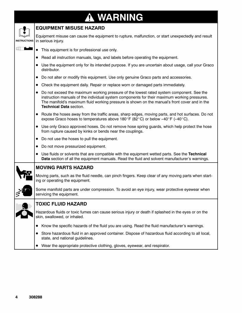
EQUIPMENT MISUSE HAZARD
Equipment misuse can cause the equipment to rupture, malfunction, or start unexpectedly and resultin serious injury.
D This equipment is for professional use only.
D Read all instruction manuals, tags, and labels before operating the equipment.
D Use the equipment only for its intended purpose. If you are uncertain about usage, call your Gracodistributor.
D Do not alter or modify this equipment. Use only genuine Graco parts and accessories.
D Check the equipment daily. Repair or replace worn or damaged parts immediately.
D Do not exceed the maximum working pressure of the lowest rated system component. See theinstruction manuals of the individual system components for their maximum working pressures.The manifold’s maximum fluid working pressure is shown on the manual’s front cover and in theTechnical Data section.
D Route the hoses away from the traffic areas, sharp edges, moving parts, and hot surfaces. Do notexpose Graco hoses to temperatures above 180_F (82_C) or below --40_F (--40_C).
D Use only Graco approved hoses. Do not remove hose spring guards, which help protect the hosefrom rupture caused by kinks or bends near the couplings.
D Do not use the hoses to pull the equipment.
D Do not move pressurized equipment.
D Use fluids or solvents that are compatible with the equipment wetted parts. See the TechnicalData section of all the equipment manuals. Read the fluid and solvent manufacturer’s warnings.
MOVING PARTS HAZARD
Moving parts, such as the fluid needle, can pinch fingers. Keep clear of any moving parts when start-ing or operating the equipment.
Some manifold parts are under compression. To avoid an eye injury, wear protective eyewear whenservicing the equipment.
TOXIC FLUID HAZARD
Hazardous fluids or toxic fumes can cause serious injury or death if splashed in the eyes or on theskin, swallowed, or inhaled.
D Know the specific hazards of the fluid you are using. Read the fluid manufacturer’s warnings.
D Store hazardous fluid in an approved container. Dispose of hazardous fluid according to all local,state, and national guidelines.
D Wear the appropriate protective clothing, gloves, eyewear, and respirator.
308288 5
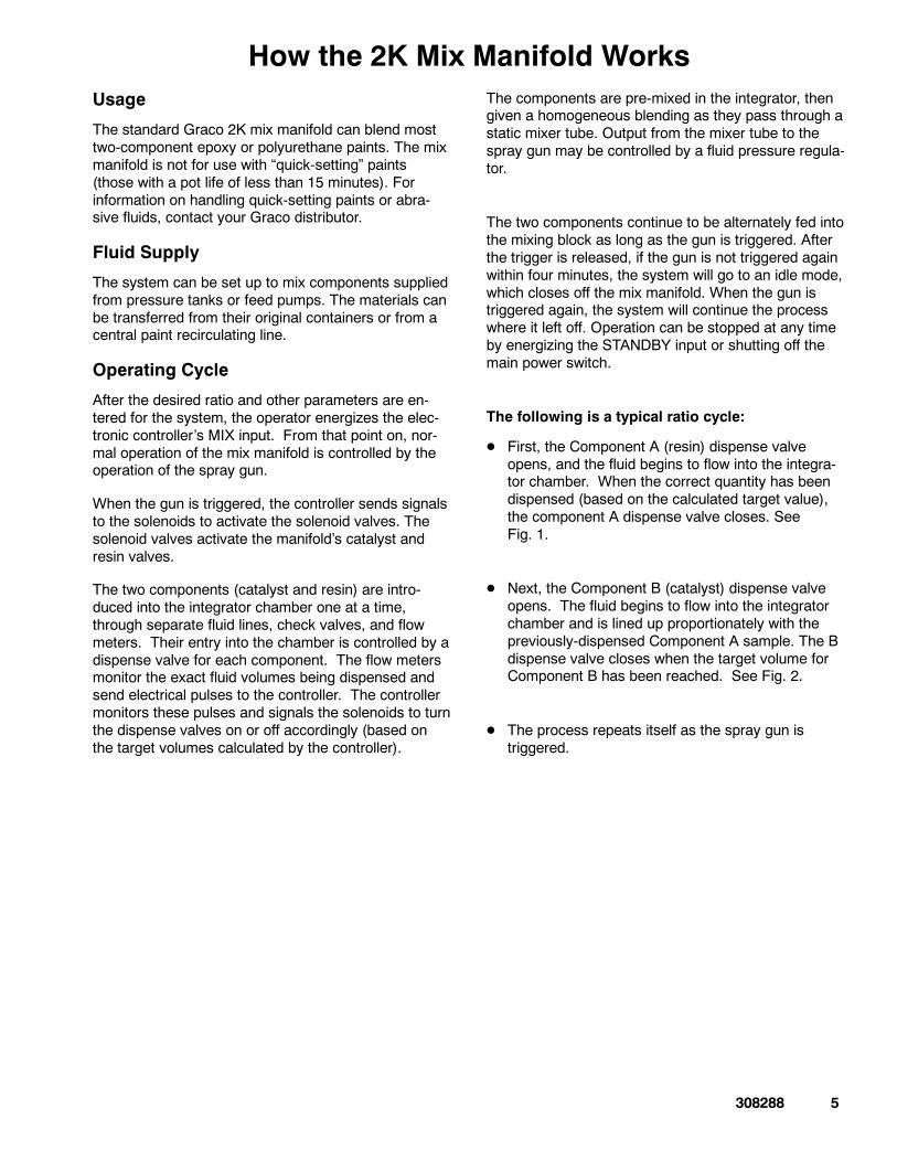
How the 2K Mix Manifold WorksUsage
The standard Graco 2K mix manifold can blend mosttwo-component epoxy or polyurethane paints. The mixmanifold is not for use with “quick-setting” paints(those with a pot life of less than 15 minutes). Forinformation on handling quick-setting paints or abra-sive fluids, contact your Graco distributor.
Fluid Supply
The system can be set up to mix components suppliedfrom pressure tanks or feed pumps. The materials canbe transferred from their original containers or from acentral paint recirculating line.
Operating Cycle
After the desired ratio and other parameters are en-tered for the system, the operator energizes the elec-tronic controller’s MIX input. From that point on, nor-mal operation of the mix manifold is controlled by theoperation of the spray gun.
When the gun is triggered, the controller sends signalsto the solenoids to activate the solenoid valves. Thesolenoid valves activate the manifold’s catalyst andresin valves.
The two components (catalyst and resin) are intro-duced into the integrator chamber one at a time,through separate fluid lines, check valves, and flowmeters. Their entry into the chamber is controlled by adispense valve for each component. The flow metersmonitor the exact fluid volumes being dispensed andsend electrical pulses to the controller. The controllermonitors these pulses and signals the solenoids to turnthe dispense valves on or off accordingly (based onthe target volumes calculated by the controller).
The components are pre-mixed in the integrator, thengiven a homogeneous blending as they pass through astatic mixer tube. Output from the mixer tube to thespray gun may be controlled by a fluid pressure regula-tor.
The two components continue to be alternately fed intothe mixing block as long as the gun is triggered. Afterthe trigger is released, if the gun is not triggered againwithin four minutes, the system will go to an idle mode,which closes off the mix manifold. When the gun istriggered again, the system will continue the processwhere it left off. Operation can be stopped at any timeby energizing the STANDBY input or shutting off themain power switch.
The following is a typical ratio cycle:
D First, the Component A (resin) dispense valveopens, and the fluid begins to flow into the integra-tor chamber. When the correct quantity has beendispensed (based on the calculated target value),the component A dispense valve closes. SeeFig. 1.
D Next, the Component B (catalyst) dispense valveopens. The fluid begins to flow into the integratorchamber and is lined up proportionately with thepreviously-dispensed Component A sample. The Bdispense valve closes when the target volume forComponent B has been reached. See Fig. 2.
D The process repeats itself as the spray gun istriggered.
6 308288
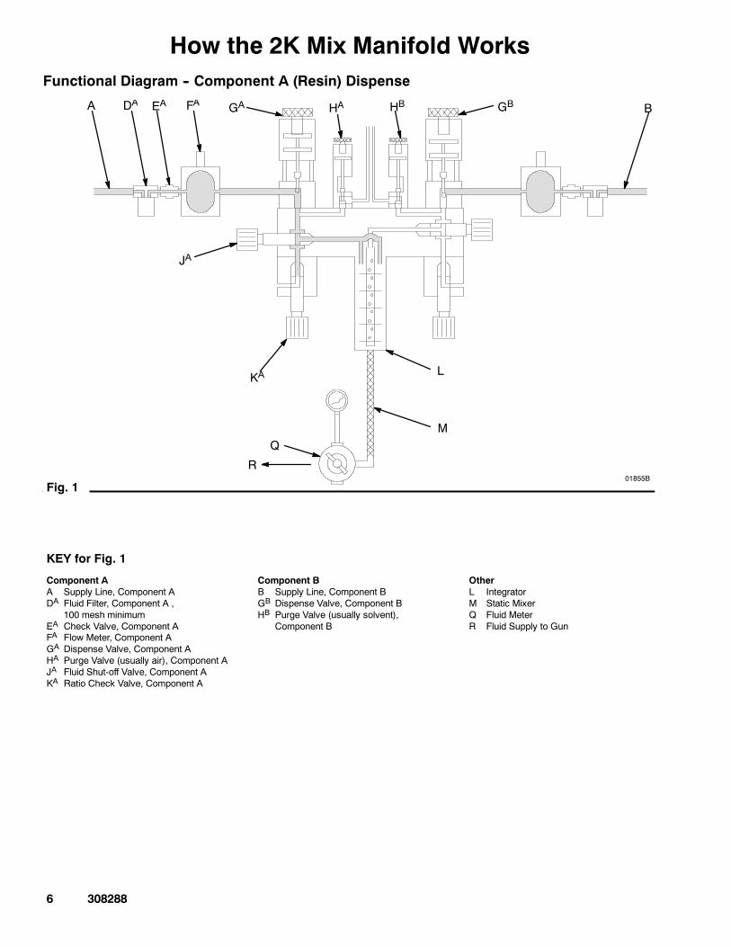
How the 2K Mix Manifold WorksFunctional Diagram -- Component A (Resin) Dispense
01855BFig. 1
A
JA
KA
M
R
L
Q
FAEADA GA BHA HB GB
KEY for Fig. 1
Component AA Supply Line, Component ADA Fluid Filter, Component A ,
100 mesh minimumEA Check Valve, Component AFA Flow Meter, Component AGA Dispense Valve, Component AHA Purge Valve (usually air), Component AJA Fluid Shut-off Valve, Component AKA Ratio Check Valve, Component A
Component BB Supply Line, Component BGB Dispense Valve, Component BHB Purge Valve (usually solvent),
Component B
OtherL IntegratorM Static MixerQ Fluid MeterR Fluid Supply to Gun
308288 7
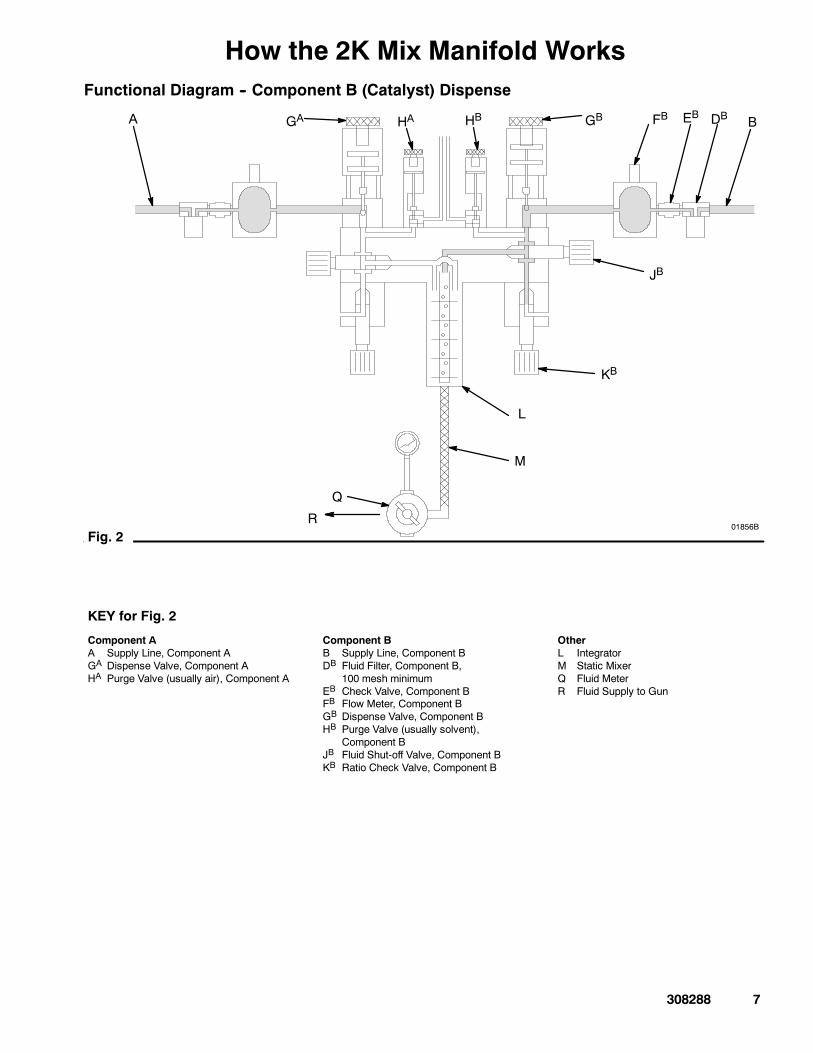
How the 2K Mix Manifold WorksFunctional Diagram -- Component B (Catalyst) Dispense
01856BFig. 2
DBEBFB
JB
KB
A
M
R
L
Q
GA BHA HB GB
KEY for Fig. 2
Component AA Supply Line, Component AGA Dispense Valve, Component AHA Purge Valve (usually air), Component A
Component BB Supply Line, Component BDB Fluid Filter, Component B,
100 mesh minimumEB Check Valve, Component BFB Flow Meter, Component BGB Dispense Valve, Component BHB Purge Valve (usually solvent),
Component BJB Fluid Shut-off Valve, Component BKB Ratio Check Valve, Component B
OtherL IntegratorM Static MixerQ Fluid MeterR Fluid Supply to Gun

8 308288
How the 3K Mix Manifold WorksUsage
The standard Graco 3K mix manifold can blend mosttwo and three component epoxy or polyurethanepaints. The mix manifold is not for use with “quick-set-ting” paints (those with a pot life of less than 15 min-utes). For information on handling quick-setting paintsor abrasive fluids, contact your Graco distributor.
Fluid Supply
The system can be set up to mix components suppliedfrom pressure tanks or feed pumps. The materials canbe transferred from their original containers or from acentral paint recirculating line.
Operating Cycle
After the desired ratios and other parameters are en-tered for the system, the operator energizes the elec-tronic controller’s MIX input. From that point on, nor-mal operation of the mix manifold is controlled by theoperation of the spray gun.
When the gun is triggered, the controller sends signalsto the solenoids to activate the solenoid valves. Thesolenoid valves activate the manifold’s resin, catalyst,and reducer valves.
The three components (resin, catalyst, and reducer)are introduced into the integrator chambers one at atime, through separate fluid lines, check valves, andflow meters. Their entry into the chambers is con-trolled by a dispense valve for each component. Theflow meters monitor the exact fluid volumes being dis-pensed and send electrical pulses to the controller.The controller monitors these pulses and signals thesolenoids to turn the dispense valves on or offaccordingly (based on the target volumes calculated bythe controller).
Components A and C are pre-mixed in the first integra-tor chamber, then given a homogeneous blending asthey pass through a static mixer tube to the secondintegrator chamber.
Component B is added in the second integrator cham-ber, and the three components are then homoge-neously blended as they pass through a second staticmixer tube. Output from the second mixer tube to thespray gun may be controlled by a fluid pressure regula-tor.
The three components continue to be alternately fedinto the mixing blocks as long as the gun is triggered.After the trigger is released, if the gun is not triggeredagain within four minutes, the system will go to an idlemode, which closes off the mix manifold. When thegun is triggered again, the system will continue theprocess where it left off. Operation can be stopped atany time by energizing the STANDBY input or shuttingoff the main power switch.
The following is a typical ratio cycle:
D First, the Component A (resin) dispense valveopens, and the fluid begins to flow into the firstintegrator chamber. When the correct quantity hasbeen dispensed (based on the calculated targetvalue), the component A dispense valve closes.See Fig. 3.
D Next, the Component B (catalyst) dispense valveopens. The fluid begins to flow into the secondintegrator chamber and is lined up proportionatelywith the previously-dispensed Component A and Cdose. The Component B dispense valve closeswhen the target volume for Component B isreached. See Fig. 2.
D The Component C (reducer) dispense valve (GC)opens and Component C flows into the first integra-tor chamber. The fluid is lined up proportionatelywith Components A and B. The Component Cdispense valve closes when the target volume forComponent C is reached. See Fig. 5.
D The process repeats itself as the spray gun istriggered.
308288 9
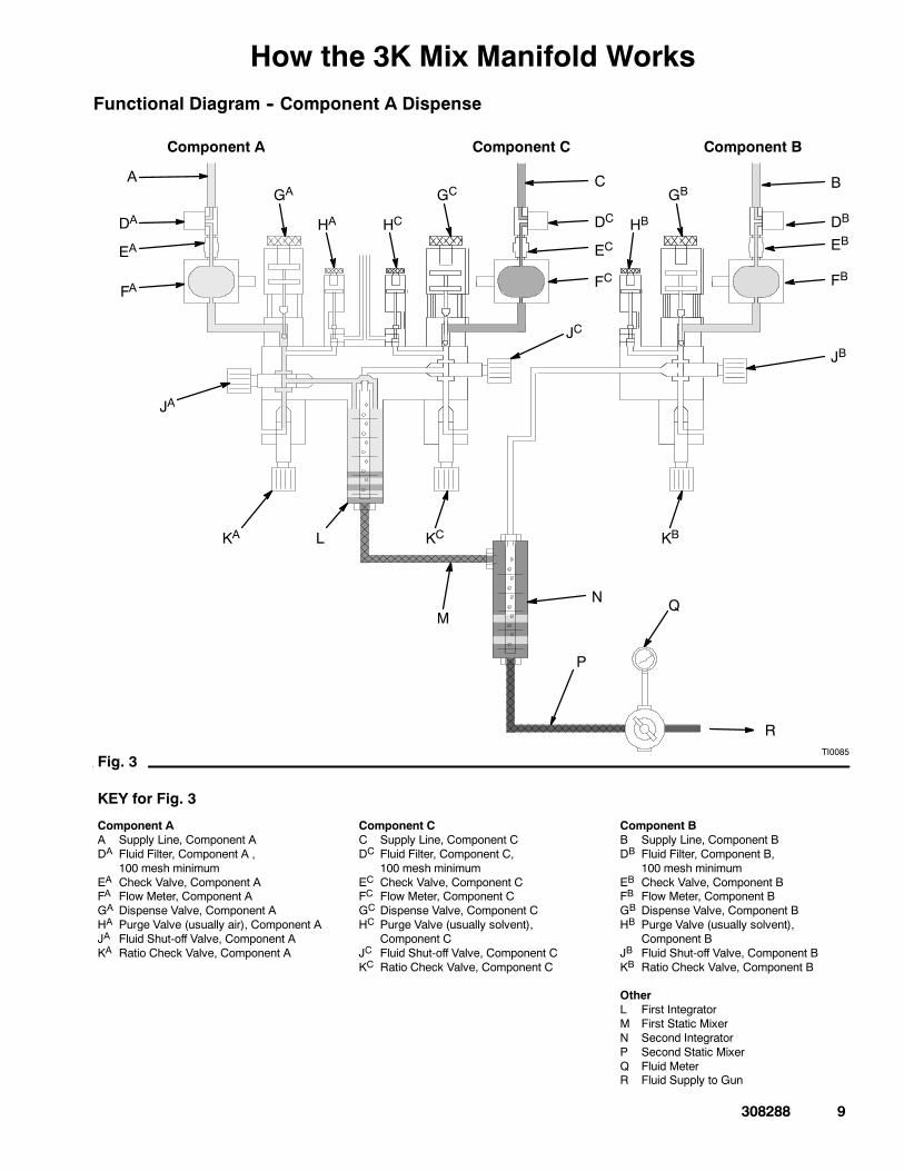
How the 3K Mix Manifold WorksFunctional Diagram -- Component A Dispense
KEY for Fig. 3
Component AA Supply Line, Component ADA Fluid Filter, Component A ,
100 mesh minimumEA Check Valve, Component AFA Flow Meter, Component AGA Dispense Valve, Component AHA Purge Valve (usually air), Component AJA Fluid Shut-off Valve, Component AKA Ratio Check Valve, Component A
Component CC Supply Line, Component CDC Fluid Filter, Component C,
100 mesh minimumEC Check Valve, Component CFC Flow Meter, Component CGC Dispense Valve, Component CHC Purge Valve (usually solvent),
Component CJC Fluid Shut-off Valve, Component CKC Ratio Check Valve, Component C
Component BB Supply Line, Component BDB Fluid Filter, Component B,
100 mesh minimumEB Check Valve, Component BFB Flow Meter, Component BGB Dispense Valve, Component BHB Purge Valve (usually solvent),
Component BJB Fluid Shut-off Valve, Component BKB Ratio Check Valve, Component B
OtherL First IntegratorM First Static MixerN Second IntegratorP Second Static MixerQ Fluid MeterR Fluid Supply to Gun
A
JA
KA
C
M
R
B
L
N Q
P
FA
EA
DA
GA
HA
KC
HC
GC
DC
EC
FC
JC
KB
HB
GB
DB
EB
FB
JB
Component A Component BComponent C
TI0085Fig. 3
10 308288
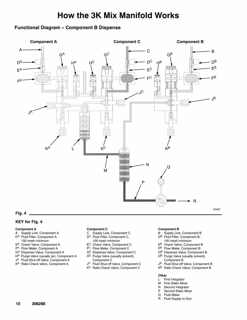
How the 3K Mix Manifold WorksFunctional Diagram -- Component B Dispense
M
R
L
N Q
P
A
JA
KA
C B
FA
EA
DA
GA
HA
KC
HC
GC
DC
EC
FC
JC
KB
HB
GB
DB
EB
FB
JB
Component A Component BComponent C
TI0087
Fig. 4
KEY for Fig. 4
Component AA Supply Line, Component ADA Fluid Filter, Component A ,
100 mesh minimumEA Check Valve, Component AFA Flow Meter, Component AGA Dispense Valve, Component AHA Purge Valve (usually air), Component AJA Fluid Shut-off Valve, Component AKA Ratio Check Valve, Component A
Component CC Supply Line, Component CDC Fluid Filter, Component C,
100 mesh minimumEC Check Valve, Component CFC Flow Meter, Component CGC Dispense Valve, Component CHC Purge Valve (usually solvent),
Component CJC Fluid Shut-off Valve, Component CKC Ratio Check Valve, Component C
Component BB Supply Line, Component BDB Fluid Filter, Component B,
100 mesh minimumEB Check Valve, Component BFB Flow Meter, Component BGB Dispense Valve, Component BHB Purge Valve (usually solvent),
Component BJB Fluid Shut-off Valve, Component BKB Ratio Check Valve, Component B
OtherL First IntegratorM First Static MixerN Second IntegratorP Second Static MixerQ Fluid MeterR Fluid Supply to Gun
308288 11
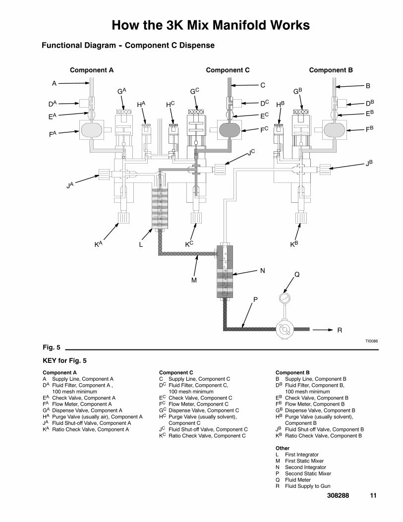
How the 3K Mix Manifold WorksFunctional Diagram -- Component C Dispense
M
R
L
N Q
P
A
JA
KA
C B
FA
EA
DA
GA
HA
KC
HC
GC
DC
EC
FC
JC
KB
HB
GB
DB
EB
FB
JB
Component A Component BComponent C
TI0086
Fig. 5
KEY for Fig. 5
Component AA Supply Line, Component ADA Fluid Filter, Component A ,
100 mesh minimumEA Check Valve, Component AFA Flow Meter, Component AGA Dispense Valve, Component AHA Purge Valve (usually air), Component AJA Fluid Shut-off Valve, Component AKA Ratio Check Valve, Component A
Component CC Supply Line, Component CDC Fluid Filter, Component C,
100 mesh minimumEC Check Valve, Component CFC Flow Meter, Component CGC Dispense Valve, Component CHC Purge Valve (usually solvent),
Component CJC Fluid Shut-off Valve, Component CKC Ratio Check Valve, Component C
Component BB Supply Line, Component BDB Fluid Filter, Component B,
100 mesh minimumEB Check Valve, Component BFB Flow Meter, Component BGB Dispense Valve, Component BHB Purge Valve (usually solvent),
Component BJB Fluid Shut-off Valve, Component BKB Ratio Check Valve, Component B
OtherL First IntegratorM First Static MixerN Second IntegratorP Second Static MixerQ Fluid MeterR Fluid Supply to Gun
12 308288
Installation
WARNINGFLAMMABLE OR TOXICVAPOR HAZARDProvide fresh air ventilation to avoid thebuildup of flammable or toxic vapors. Donot operate the spray gun unless ventila-tion fans are operating. Follow all nation-al, state, and local codes regarding airexhaust velocity requirements.
NOTE:
D Have the system binder (a collection of manualsand diagrams in a three-ring binder, supplied withthe system by Graco) available during installation.
D Reference numbers and letters in parentheses inthis manual’s text refer to the numbers and lettersin the illustrations.
D Be sure all accessories are adequately sized andpressure-rated to meet the system’s requirements.
D Connect the fluid and air supply lines as instructedin this manual and the system binder.
The following instructions generally presume a stan-dard system using pressure tanks to supply the paintcomponents and solvent. See also Optional FluidSupplies, below, for possible variations and theireffect on the instructions.
Fluid Supply
The following installation and operation instructionsgenerally presume a standard system, using pressuretanks to supply the paint components and solvent.The Optional Fluid Supplies listed below are twopossible variations and their effects on the instructions.
Optional Fluid Supplies
NOTE: The fluid supply must be free of pressurespikes, which are commonly caused by a pump strokechangeover. If necessary, install pressure regulatorsor a surge tank on the fluid inlets to the mix manifold,to reduce the fluid supply pressure. Contact Graco forinformation on fluid pressure regulators.
Supplying Fluid Through Circulating Lines
If there is a central paint recirculating line in your shop,the mix manifold can be connected to it instead of topressure tanks. Other than references to the pressuretanks, operation is the same as described in this man-ual.
For maintenance and safety, you must install a ballvalve between each supply line and the mix manifold.
Supplying Fluid Through Pail or Drum Pumps
Instead of pressure tanks, the mix manifold can besupplied by pail or drum pumps. Operation is thesame, other than references to the pressure tanks.
308288 13
InstallationGround the Mix Manifold
WARNINGFIRE, EXPLOSION, AND ELECTRICSHOCK HAZARDTo reduce the risk of fire, explosion, orelectric shock:
D The mix manifold must be electricallyconnected to a true earth ground; theground in the electrical system is notsufficient.
D All wires used for grounding must be10 gauge minimum.
D Refer to your local code for the requirements fora “true earth ground” in your area.
D Also read and follow the warnings on page 2and the grounding instructions in your separatecomponent and system manuals.
Connect the ground wire to the mix manifold or to themix manifold mounting surface if there is electricalcontinuity between the mounting surface and the mixmanifold.
Be sure to follow the specific grounding instructions forthe system. The system you install the mix manifoldinto may have special grounding requirements for themix manifold.
NOTE: A ground wire and clamp, part no. 222011, isavailable from Graco.
Check the Resistance
WARNINGFIRE, EXPLOSION, AND ELECTRICSHOCK HAZARDTo reduce the risk of fire, explosion, orelectric shock the resistance betweenthe system components and true earthground must be less than 25 ohms.
Have a qualified electrician check the resistance be-tween each system component and the true earthground. The resistance must be less than 25 ohms. Ifthe resistance is greater than 25 ohms, a differentground site may be required. Do not operate the sys-tem until the problem is corrected.
14 308288
Installation
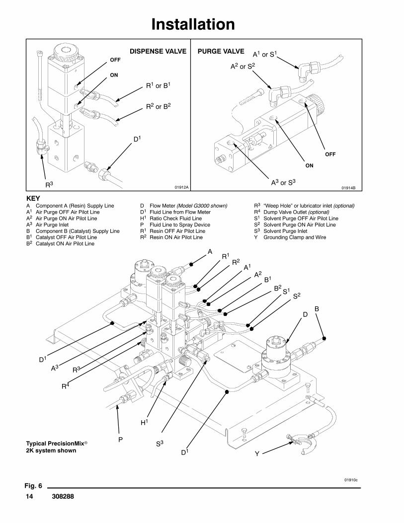
Fig. 6
R1R2
A1A2
KEYA Component A (Resin) Supply LineA1 Air Purge OFF Air Pilot LineA2 Air Purge ON Air Pilot LineA3 Air Purge InletB Component B (Catalyst) Supply LineB1 Catalyst OFF Air Pilot LineB2 Catalyst ON Air Pilot Line
D Flow Meter (Model G3000 shown)D1 Fluid Line from Flow MeterH1 Ratio Check Fluid LineP Fluid Line to Spray DeviceR1 Resin OFF Air Pilot LineR2 Resin ON Air Pilot Line
R3 “Weep Hole” or lubricator inlet (optional)R4 Dump Valve Outlet (optional)S1 Solvent Purge OFF Air Pilot LineS2 Solvent Purge ON Air Pilot LineS3 Solvent Purge InletY Grounding Clamp and Wire
B1
B2 S1S2
BD
D1S3
H1
P
R4
R3D1
A3
A
Y
DISPENSE VALVE PURGE VALVEOFF
ON
OFF
ON
R1 or B1
R2 or B2
D1
R3 A3 or S3
A2 or S2A1 or S1
01912A 01914B
Typical PrecisionMixr2K system shown
01910c
308288 15
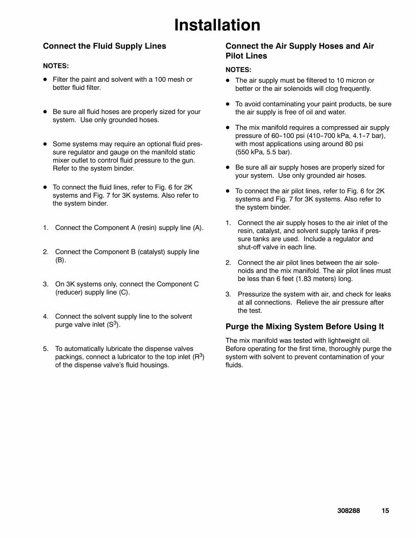
InstallationConnect the Fluid Supply Lines
NOTES:
D Filter the paint and solvent with a 100 mesh orbetter fluid filter.
D Be sure all fluid hoses are properly sized for yoursystem. Use only grounded hoses.
D Some systems may require an optional fluid pres-sure regulator and gauge on the manifold staticmixer outlet to control fluid pressure to the gun.Refer to the system binder.
D To connect the fluid lines, refer to Fig. 6 for 2Ksystems and Fig. 7 for 3K systems. Also refer tothe system binder.
1. Connect the Component A (resin) supply line (A).
2. Connect the Component B (catalyst) supply line(B).
3. On 3K systems only, connect the Component C(reducer) supply line (C).
4. Connect the solvent supply line to the solventpurge valve inlet (S3).
5. To automatically lubricate the dispense valvespackings, connect a lubricator to the top inlet (R3)of the dispense valve’s fluid housings.
Connect the Air Supply Hoses and AirPilot Lines
NOTES:
D The air supply must be filtered to 10 micron orbetter or the air solenoids will clog frequently.
D To avoid contaminating your paint products, be surethe air supply is free of oil and water.
D The mix manifold requires a compressed air supplypressure of 60--100 psi (410--700 kPa, 4.1--7 bar),with most applications using around 80 psi(550 kPa, 5.5 bar).
D Be sure all air supply hoses are properly sized foryour system. Use only grounded air hoses.
D To connect the air pilot lines, refer to Fig. 6 for 2Ksystems and Fig. 7 for 3K systems. Also refer tothe system binder.
1. Connect the air supply hoses to the air inlet of theresin, catalyst, and solvent supply tanks if pres-sure tanks are used. Include a regulator andshut-off valve in each line.
2. Connect the air pilot lines between the air sole-noids and the mix manifold. The air pilot lines mustbe less than 6 feet (1.83 meters) long.
3. Pressurize the system with air, and check for leaksat all connections. Relieve the air pressure afterthe test.
Purge the Mixing System Before Using It
The mix manifold was tested with lightweight oil.Before operating for the first time, thoroughly purge thesystem with solvent to prevent contamination of yourfluids.
16 308288
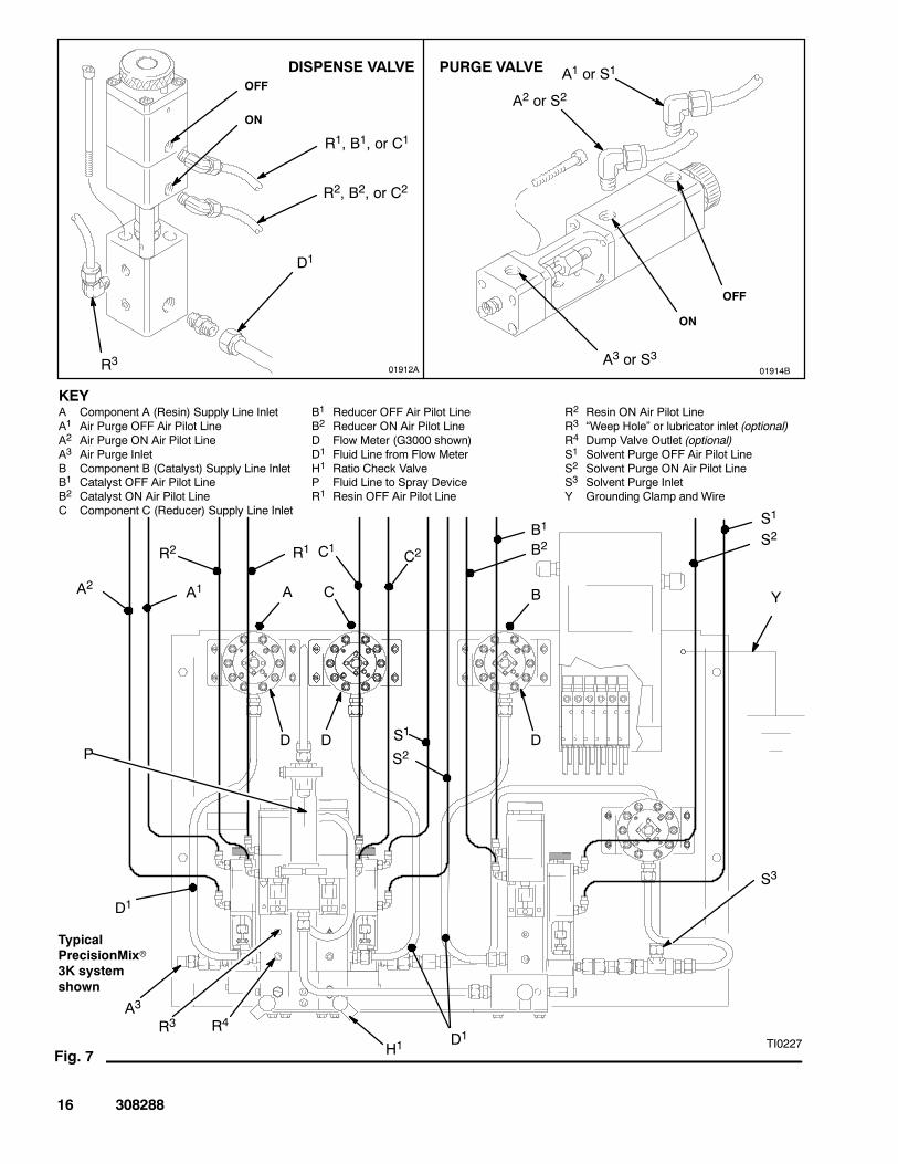
Fig. 7
R1R2
A1A2
KEYA Component A (Resin) Supply Line InletA1 Air Purge OFF Air Pilot LineA2 Air Purge ON Air Pilot LineA3 Air Purge InletB Component B (Catalyst) Supply Line InletB1 Catalyst OFF Air Pilot LineB2 Catalyst ON Air Pilot LineC Component C (Reducer) Supply Line Inlet
B1 Reducer OFF Air Pilot LineB2 Reducer ON Air Pilot LineD Flow Meter (G3000 shown)D1 Fluid Line from Flow MeterH1 Ratio Check ValveP Fluid Line to Spray DeviceR1 Resin OFF Air Pilot Line
R2 Resin ON Air Pilot LineR3 “Weep Hole” or lubricator inlet (optional)R4 Dump Valve Outlet (optional)S1 Solvent Purge OFF Air Pilot LineS2 Solvent Purge ON Air Pilot LineS3 Solvent Purge InletY Grounding Clamp and Wire
C1 C2
S1
S2
D1H1
P
R4R3
D1
A3
Y
DISPENSE VALVE PURGE VALVEOFF
ON
OFF
ON
R1, B1, or C1
R2, B2, or C2
D1
R3 A3 or S3
A2 or S2A1 or S1
01912A 01914B
TypicalPrecisionMixr3K systemshown
TI0227
C B
B1
B2
D D
S1
S2
S3
D
A
308288 17
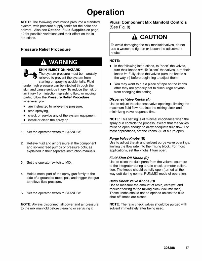
OperationNOTE: The following instructions presume a standardsystem, with pressure supply tanks for the paint andsolvent. Also see Optional Fluid Supplies on page12 for possible variations and their effect on the in-structions.
Pressure Relief Procedure
WARNINGSKIN INJECTION HAZARDThe system pressure must be manuallyrelieved to prevent the system fromstarting or spraying accidentally. Fluid
under high pressure can be injected through theskin and cause serious injury. To reduce the risk ofan injury from injection, splashing fluid, or movingparts, follow the Pressure Relief Procedurewhenever you:
D are instructed to relieve the pressure,D stop spraying,D check or service any of the system equipment,D install or clean the spray tip.
1. Set the operator switch to STANDBY.
2. Relieve fluid and air pressure at the componentand solvent feed pumps or pressure pots, asexplained in their separate instruction manuals.
3. Set the operator switch to MIX.
4. Hold a metal part of the spray gun firmly to theside of a grounded metal pail, and trigger the gunto relieve fluid pressure.
5. Set the operator switch to STANDBY.
NOTE: Always disconnect all power and air pressureto the mix manifold before cleaning or servicing it.
Plural Component Mix Manifold Controls(See Fig. 8)
CAUTIONTo avoid damaging the mix manifold valves, do notuse a wrench to tighten or loosen the adjustmentknobs.
NOTE:
D In the following instructions, to “open” the valves,turn their knobs out. To “close” the valves, turn theirknobs in. Fully close the valves (turn the knobs allthe way in) before beginning to adjust them.
D You may want to put a piece of tape on the knobsafter they are properly set to discourage anyonefrom changing the setting.
Dispense Valve Knobs (A)Use to adjust the dispense valve openings, limiting themaximum fluid flow rate into the mixing block andminimizing valve response time.
NOTE: This setting is of minimal importance when thespray gun controls the process, except that the valvesmust be open enough to allow adequate fluid flow. Formost applications, set the knobs 2/3 of a turn open.
Purge Valve Knobs (B)Use to adjust the air and solvent purge valve openings,limiting the flow rate into the mixing block. For mostapplications, set the knobs 1 turn open.
Fluid Shut-Off Knobs (C)Use to close the fluid ports from the volume countersto the integrator during a ratio check or meter calibra-tion. The knobs should be fully open (turned all theway out) during normal RUN/MIX mode of operation.
Ratio Check Valve Knobs (D)Use to measure the amount of resin, catalyst, andreducer flowing to the mixing block (volume ratio).These knobs should not be opened unless the fluidshut-off knobs are closed.
NOTE: The ratio check valves should be purged withsolvent immediately after being used.
18 308288
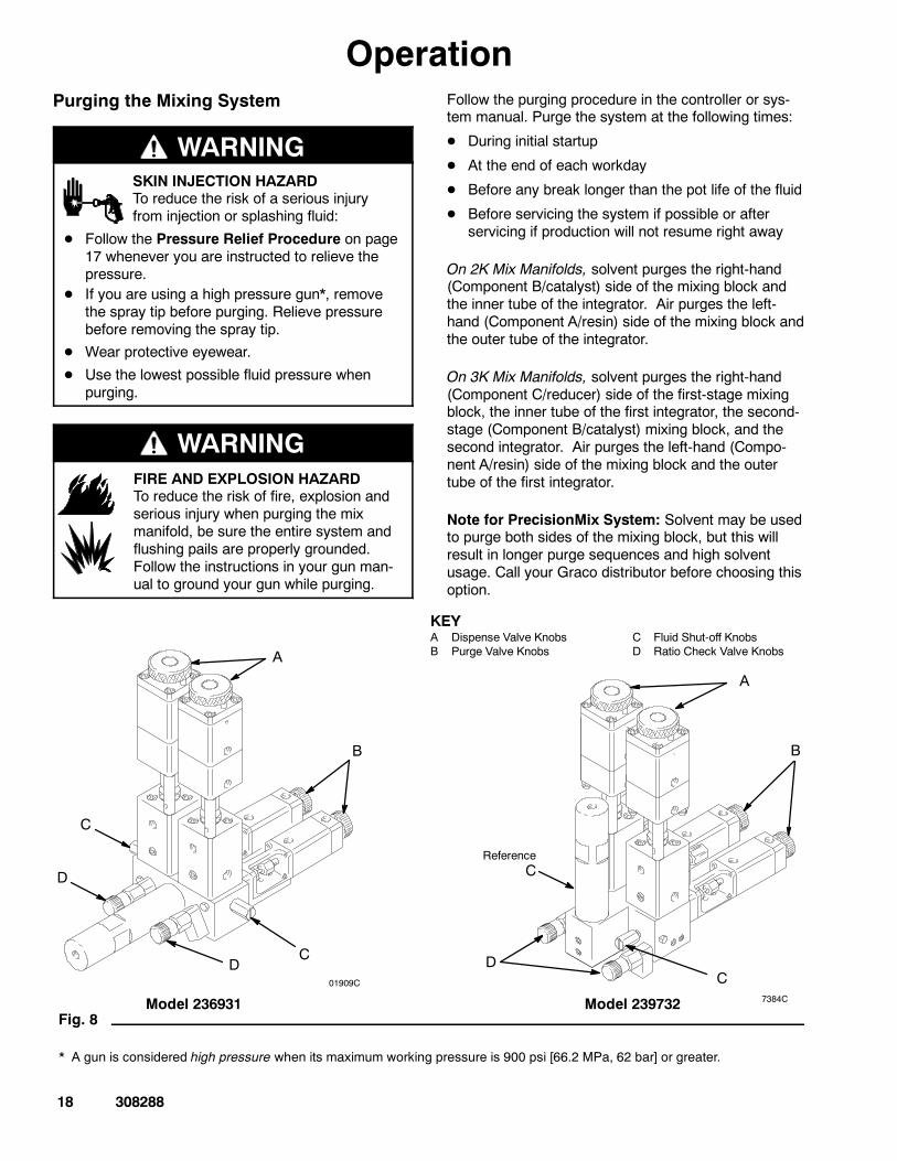
OperationPurging the Mixing System
WARNINGSKIN INJECTION HAZARDTo reduce the risk of a serious injuryfrom injection or splashing fluid:
D Follow the Pressure Relief Procedure on page17 whenever you are instructed to relieve thepressure.
D If you are using a high pressure gun*, removethe spray tip before purging. Relieve pressurebefore removing the spray tip.
D Wear protective eyewear.
D Use the lowest possible fluid pressure whenpurging.
WARNINGFIRE AND EXPLOSION HAZARDTo reduce the risk of fire, explosion andserious injury when purging the mixmanifold, be sure the entire system andflushing pails are properly grounded.Follow the instructions in your gun man-ual to ground your gun while purging.
Follow the purging procedure in the controller or sys-tem manual. Purge the system at the following times:
D During initial startup
D At the end of each workday
D Before any break longer than the pot life of the fluid
D Before servicing the system if possible or afterservicing if production will not resume right away
On 2K Mix Manifolds, solvent purges the right-hand(Component B/catalyst) side of the mixing block andthe inner tube of the integrator. Air purges the left-hand (Component A/resin) side of the mixing block andthe outer tube of the integrator.
On 3K Mix Manifolds, solvent purges the right-hand(Component C/reducer) side of the first-stage mixingblock, the inner tube of the first integrator, the second-stage (Component B/catalyst) mixing block, and thesecond integrator. Air purges the left-hand (Compo-nent A/resin) side of the mixing block and the outertube of the first integrator.
Note for PrecisionMix System: Solvent may be usedto purge both sides of the mixing block, but this willresult in longer purge sequences and high solventusage. Call your Graco distributor before choosing thisoption.
Fig. 8
A
KEYA Dispense Valve KnobsB Purge Valve Knobs
C Fluid Shut-off KnobsD Ratio Check Valve Knobs
B
D
C
ReferenceC
C
A
B
D
Model 239732
C
D01909C
Model 236931 7384C
* A gun is considered high pressure when its maximum working pressure is 900 psi [66.2 MPa, 62 bar] or greater.
308288 19
OperationSetting the Fluid Supply Pressure
Turn on the air supply and recharge the paint andsolvent tanks with air. Adjust the air pressure to:
Solvent: 70 psi (480 kPa, 4.8 bar).
Resin, Catalyst, and Reducer: 30--70 psi (210--480kPa, 2.1--4.8 bar).
Fluid pressures should be equal unless one compo-nent is more viscous, in which case the more viscouscomponent could require a higher pressure setting.Adjust the pressures until the fluid flow rate at the gunis the same for the Component A, B and C (3K only)dispense.
Starting Production
WARNINGSKIN INJECTION HAZARDTo reduce the risk of a serious injuryfrom accidental spray from the gun,splashing fluid, or moving parts, follow
the Pressure Relief Procedure on page 17 when-ever you:
D are instructed to relieve the pressure,D stop spraying,D check or service any of the system equipment,D install or clean the spray tip.
NOTE:
D The operation of the manifold is dependent on theoperation of the controller and the controller set-tings. See the controller or system manual for com-plete startup, ratio check, purging, and productionprocedures.
D When you first start up the system after it has beenshut down for a period of time, the relays, sole-noids, and valves for Components A, B and C (3Konly) will cycle rapidly until system pressure is builtback up. This is normal.
1. Check that the fluid supplies for the ComponentsA, B and C (3K only), and solvent are filled.
2. Check that fluid valves are turned on and the fluidpressure to the mix manifold is properly set.
3. Check that the air pressure to the solenoids isproperly set.
4. Check that the mix manifold fluid shut-off knobs,dispense valve knobs, and purge valve knobs areset properly. Start with the settings recommendedin Plural Component Mix Manifold Controls onpage 17, then adjust the valves as needed.
5. Follow the operating instructions for your controlleror system.
During Production:
D Make sure that all air is removed from the fluid linesof the system.
D If the fluid output is too low or too high, adjust thefluid pressure with the fluid supply pressure regula-tors.
CAUTIONDo not use the first 4 to 5 oz. (120 to 150 ml) ofmaterial from the system, as it may not be thor-oughly mixed due to alarms while loading materialinto the system.
D Check the fluid supply pressure regulators. Thefluid flow rate at the spray gun should be the sameregardless of whether the Component A, B and C(3K only) dispense valves are open. The pressureadjustments of each component will vary with eachcomponents viscosity. In general, start with thesame feed pressures for Component A, B and C(3K only).
D Check or reset the air regulator in the atomizing airline.
20 308288
MaintenanceDaily Maintenance
D Purge the mixing system at the end of production.
D Check the fluid supplies for the Component A,Component B, Component C (3K only), and solventand refill them as necessary.
D Inspect the manifold and other fluid line compo-nents for fluid leaks.
D Make sure the meter cables and air pilot lines aresecurely connected.
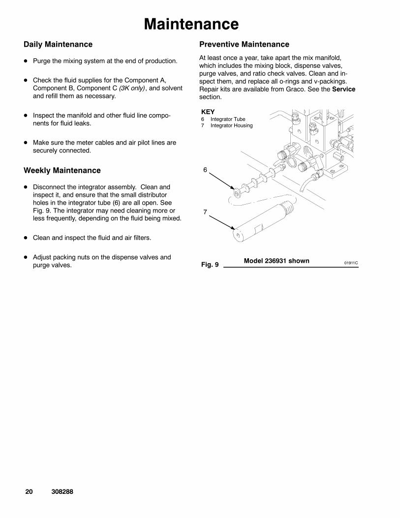
Weekly Maintenance
D Disconnect the integrator assembly. Clean andinspect it, and ensure that the small distributorholes in the integrator tube (6) are all open. SeeFig. 9. The integrator may need cleaning more orless frequently, depending on the fluid being mixed.
D Clean and inspect the fluid and air filters.
D Adjust packing nuts on the dispense valves andpurge valves.
Preventive Maintenance
At least once a year, take apart the mix manifold,which includes the mixing block, dispense valves,purge valves, and ratio check valves. Clean and in-spect them, and replace all o-rings and v-packings.Repair kits are available from Graco. See the Servicesection.
Fig. 9
KEY6 Integrator Tube7 Integrator Housing
6
7
01911CModel 236931 shown

308288 21
Troubleshooting
WARNINGSKIN INJECTION HAZARDTo reduce the risk of a serious injuryfrom accidental spray from the gun,splashing fluid, or moving parts, follow
the Pressure Relief Procedure on page 17 beforechecking or servicing the system and wheneveryou are instructed to relieve the pressure.
WARNINGELECTRIC SHOCK HAZARDTo reduce the risk of serious injury, in-cluding electric shock, the equipmentmust only be serviced by trained, quali-fied personnel.
CAUTIONTo avoid damaging the mix manifold valves, do notuse a wrench to tighten or loosen the adjustmentknobs.
NOTE: Have the system binder (collection of manualsand diagrams in a three-ring binder, supplied with thesystem by Graco) available before you begin trouble-shooting.
An operational problem can be caused by a problemwith the meters, controller, solenoid valves, as well asthe manifold.
1. Check the system for any visible faults or errors tohelp isolate the problem:
a. Check that all of the air and fluid tubes, hoses,and electrical cables are properly connected.
b. Check that the system valves and controls areproperly set for operation.
c. Check that the fluid supply, solenoids, andspray gun have sufficient air pressure.
d. Check the fluid supplies for the Component A,Component B, Component C (3K only), andsolvent and refill them as necessary.
2. If there is a fluid flow problem, refer to the Func-tional Diagrams on page 6 to see how the fluidshould flow through the manifold.
3. If there is a process control problem, refer to thecontroller manual.
Common Causes for Mixing Problems
D The flow rate is too high
D Highly unbalanced pressures from the fluid supplysystem
D Slow actuation of the resin, catalyst, or reducervalves
D System Leaks
Checking for Unbalanced Pressures
1. Check the resin, catalyst, and reducer pressures.
2. If the pressures are not about equal, adjust bothfluid supply pressures with the fluid regulators,until the pressures are about the same.
3. If the pressures are already about equal, verifythat the resin, catalyst, and reducer valves areoperating properly.
Checking the Actuation of the Valves
Manually operate the valves by actuating the sole-noids. The valves should snap open and shut quickly.If the valves move slowly, it could be caused by:
D air pressure to the valve actuators is too low,
D an interruption in the valve actuating air caused bydirt or water in the air,
D something restricting the solenoid or tubing,
D the packings on the dispense valves are too tight orthey need lubrication (see Service section),
D air piston o-rings and packings are not lubricated(see Service section),
D a dispense valve knob is turned out too far. SeePlural Component Mix Manifold Controls onpage 17, for recommended settings.
22 308288
Service
CAUTIONPurge the mix manifold with solvent after servicing toremove any excess grease that is used for lubricat-ing parts.
Tools Needed
D Set of metric open-end wrenches
D Set of metric hex key wrenches
D Various retaining ring pliers
D Flat-blade screwdrivers
D Dielectric grease (Graco part no. 217115)
Disassembling the Dispense Valves
WARNINGSKIN INJECTION HAZARDTo reduce the risk of a serious injuryfrom accidental spray from the gun,splashing fluid, or moving parts, follow
the Pressure Relief Procedure on page 17 beforechecking or servicing the system and wheneveryou are instructed to relieve the pressure.
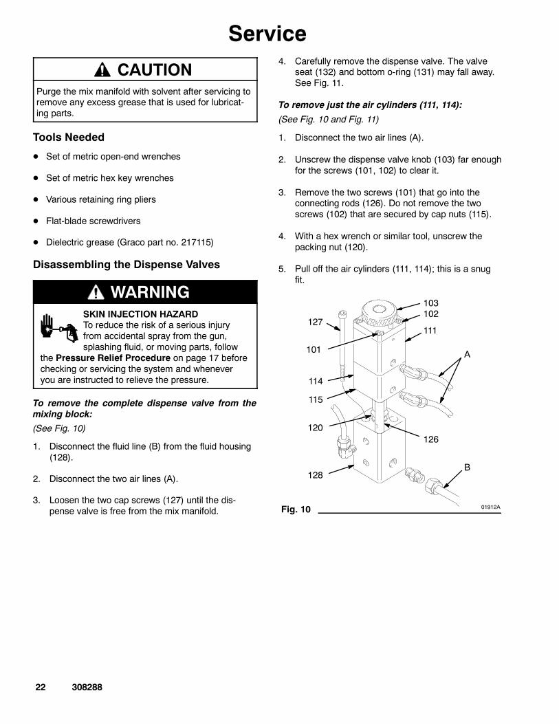
To remove the complete dispense valve from themixing block:
(See Fig. 10)
1. Disconnect the fluid line (B) from the fluid housing(128).
2. Disconnect the two air lines (A).
3. Loosen the two cap screws (127) until the dis-pense valve is free from the mix manifold.
4. Carefully remove the dispense valve. The valveseat (132) and bottom o-ring (131) may fall away.See Fig. 11.
To remove just the air cylinders (111, 114):
(See Fig. 10 and Fig. 11)
1. Disconnect the two air lines (A).
2. Unscrew the dispense valve knob (103) far enoughfor the screws (101, 102) to clear it.
3. Remove the two screws (101) that go into theconnecting rods (126). Do not remove the twoscrews (102) that are secured by cap nuts (115).
4. With a hex wrench or similar tool, unscrew thepacking nut (120).
5. Pull off the air cylinders (111, 114); this is a snugfit.
103
A
B
126
128
120
115
127
101
111
114
01912A
102
Fig. 10
308288 23
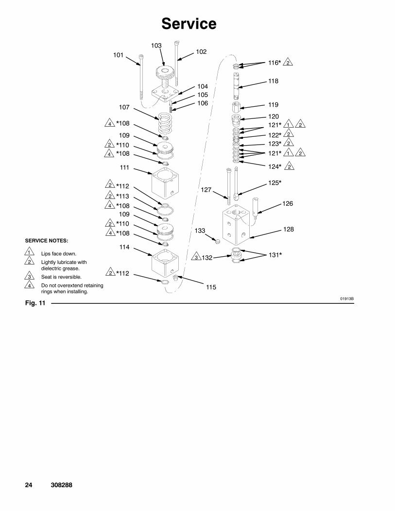
ServiceTo disassemble the top air cylinder (111):
WARNINGMOVING PARTS HAZARDThe air cylinders (111, 114) of the valveare spring-loaded, and parts may fly outor spring apart when the valve is disas-
sembled. To reduce the risk of an eye injury, wearprotective eyewear and follow the procedure below.
(See Fig. 10 and Fig. 11)
NOTE: Repair Kit 15E013 is available to repair thedispense valves. Order one kit for each valve. Therepair parts in the kit are marked with an asterisk (*) inFig. 11.
If the retaining rings (108*) do not fit on the shaft, orderkit 15E010 for a current replacement shaft (118).
1. Remove the top air cylinder (111); see previousprocedure.
2. Unscrew the dispense valve knob (103).
3. Slowly remove the two screws (102) secured bycap nuts (115), while holding the cylinder cap (104)down.
Be careful, the air cylinders (111, 114) are undercompression and will spring apart and the detentpin (105) will spring out from the cylinder cap(104). Slowly let up on the cap to release thespring compression.
4. Remove the top retaining ring (108*) from thevalve shaft (118).
5. Pull the valve shaft (118) down and hook it underthe top piston (109) with a hex wrench or similartool.
6. Remove the remaining retaining rings (108*) tocomplete the disassembly of the air cylinders.
7. Clean and inspect all parts. Inspect the o-rings(110, 112, 113, 116) on the pistons (109) and valveshaft (118). Replace parts as necessary. Lightlylubricate the o-rings with dielectric grease. As-semble parts in reverse order of disassembly.
When reassembling, be sure the two air connectionports will be facing the outside of the machine. Set theknob (103) 2/3 of a turn open from fully closed.
NOTE: DO NOT overextend retaining rings (108*)when installing.
To disassemble the fluid housing (128):(See Fig. 10 and Fig. 11)
1. Remove the top air cylinder (111); see previouspage.
2. Remove the glands (122, 123, 124) and v-pack-ings (121) from the fluid housing (128).
3. Clean and inspect all parts. Inspect the fluidneedle (125), seat (132), and o-rings (131) forwear. If only one side of the seat is worn, the seatcan be reversed and reused.
4. Replace parts as necessary. Lightly lubricate thepackings with dielectric grease. Assemble parts inreverse order of disassembly.
5. Adjust the packing nut (120).
24 308288
Service
101103
102
104105106
107
*108
109*110*108
111
*112
*113*108109*110*108
114
*112
115
132 131*
128
126
125*127
124*
121*123*
121*120
119
118
116*
122*
1 Lips face down.
Lightly lubricate withdielectric grease.
Seat is reversible.
Do not overextend retainingrings when installing.
SERVICE NOTES:
01913B
133
2
3
2
2
2
2
2
1
1
2
2
2
2
3
2
2
Fig. 11
4
4
4
4
4
308288 25
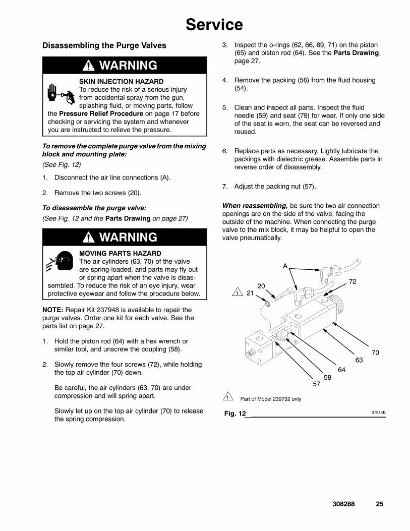
ServiceDisassembling the Purge Valves
WARNINGSKIN INJECTION HAZARDTo reduce the risk of a serious injuryfrom accidental spray from the gun,splashing fluid, or moving parts, follow
the Pressure Relief Procedure on page 17 beforechecking or servicing the system and wheneveryou are instructed to relieve the pressure.
To remove the completepurge valve from themixingblock and mounting plate:
(See Fig. 12)
1. Disconnect the air line connections (A).
2. Remove the two screws (20).
To disassemble the purge valve:
(See Fig. 12 and the Parts Drawing on page 27)
WARNINGMOVING PARTS HAZARDThe air cylinders (63, 70) of the valveare spring-loaded, and parts may fly outor spring apart when the valve is disas-
sembled. To reduce the risk of an eye injury, wearprotective eyewear and follow the procedure below.
NOTE: Repair Kit 237948 is available to repair thepurge valves. Order one kit for each valve. See theparts list on page 27.
1. Hold the piston rod (64) with a hex wrench orsimilar tool, and unscrew the coupling (58).
2. Slowly remove the four screws (72), while holdingthe top air cylinder (70) down.
Be careful, the air cylinders (63, 70) are undercompression and will spring apart.
Slowly let up on the top air cylinder (70) to releasethe spring compression.
3. Inspect the o-rings (62, 66, 69, 71) on the piston(65) and piston rod (64). See the Parts Drawing,page 27.
4. Remove the packing (56) from the fluid housing(54).
5. Clean and inspect all parts. Inspect the fluidneedle (59) and seat (79) for wear. If only one sideof the seat is worn, the seat can be reversed andreused.
6. Replace parts as necessary. Lightly lubricate thepackings with dielectric grease. Assemble parts inreverse order of disassembly.
7. Adjust the packing nut (57).
When reassembling, be sure the two air connectionopenings are on the side of the valve, facing theoutside of the machine. When connecting the purgevalve to the mix block, it may be helpful to open thevalve pneumatically.
58
20
64
A
7063
01914B
57
72
1 Part of Model 239732 only
1 21
Fig. 12
26 308288
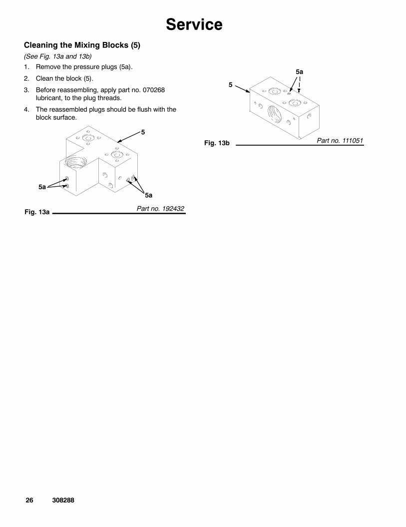
ServiceCleaning the Mixing Blocks (5)(See Fig. 13a and 13b)
1. Remove the pressure plugs (5a).
2. Clean the block (5).
3. Before reassembling, apply part no. 070268lubricant, to the plug threads.
4. The reassembled plugs should be flush with theblock surface.
Fig. 13a
5
5a
Part no. 192432
5a
Fig. 13b
5a
5
Part no. 111051
308288 27
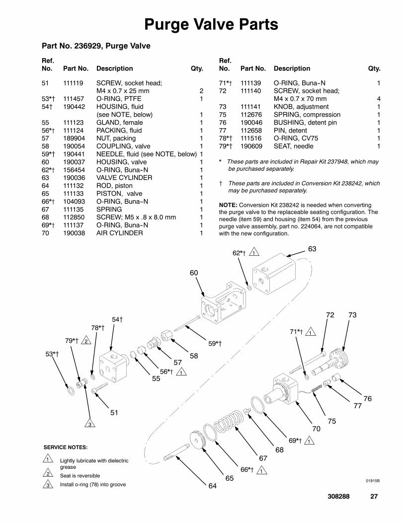
Purge Valve PartsPart No. 236929, Purge Valve
Ref.No. Part No. Description Qty.
Ref.No. Part No. Description Qty.
51 111119 SCREW, socket head;M4 x 0.7 x 25 mm 2
53*{ 111457 O-RING, PTFE 154{ 190442 HOUSING, fluid
(see NOTE, below) 155 111123 GLAND, female 156*{ 111124 PACKING, fluid 157 189904 NUT, packing 158 190054 COUPLING, valve 159*{ 190441 NEEDLE, fluid (see NOTE, below) 160 190037 HOUSING, valve 162*{ 156454 O-RING, Buna--N 163 190036 VALVE CYLINDER 164 111132 ROD, piston 165 111133 PISTON, valve 166*{ 104093 O-RING, Buna--N 167 111135 SPRING 168 112850 SCREW; M5 x .8 x 8.0 mm 169*{ 111137 O-RING, Buna--N 170 190038 AIR CYLINDER 1
71*{ 111139 O-RING, Buna--N 172 111140 SCREW, socket head;
M4 x 0.7 x 70 mm 473 111141 KNOB, adjustment 175 112676 SPRING, compression 176 190046 BUSHING, detent pin 177 112658 PIN, detent 178*{ 111516 O-RING, CV75 179*{ 190609 SEAT, needle 1
* These parts are included in Repair Kit 237948, which maybe purchased separately.
{ These parts are included in Conversion Kit 238242, whichmay be purchased separately.
NOTE: Conversion Kit 238242 is needed when convertingthe purge valve to the replaceable seating configuration. Theneedle (item 59) and housing (item 54) from the previouspurge valve assembly, part no. 224064, are not compatiblewith the new configuration.
51
53*{
54{
5556*{
5758
59*{
60
62*{ 63
6465
66*{
6768
69*{
70
71*{
72 73
01915B
78*{
79*{
75
7776
1 Lightly lubricate with dielectricgrease
Seat is reversible
Install o-ring (78) into groove
SERVICE NOTES:
2
1
2
1
1
1
1
3
3
28 308288
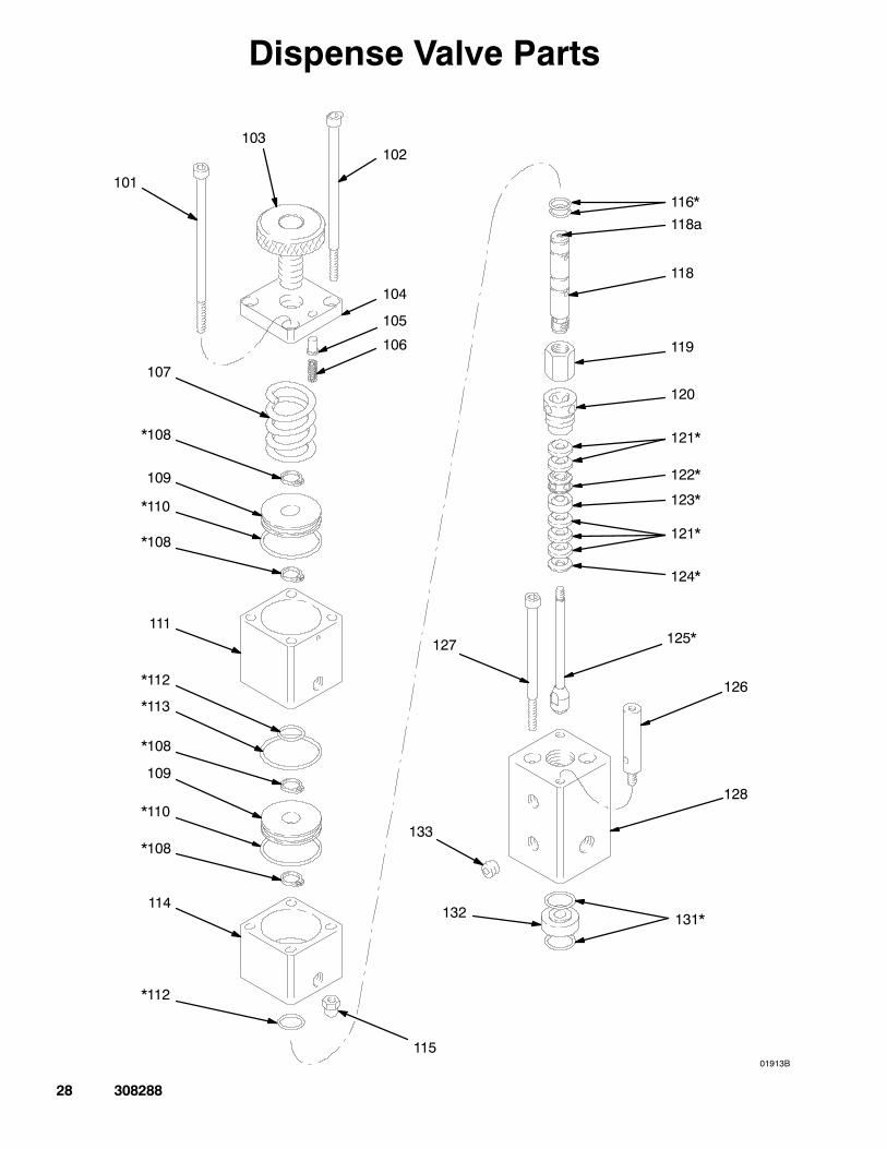
Dispense Valve Parts
101
103102
104
105
106
107
*108
109
*110
*108
111
*112
*113
*108
109
*110
*108
114
*112
115
132 131*
128
126
125*127
124*
121*
123*
121*
120
119
118
118a
116*
122*
01913B
133
308288 29
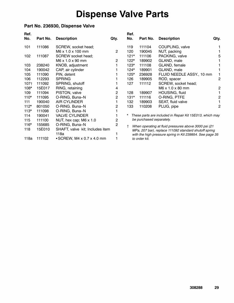
Dispense Valve PartsPart No. 236930, Dispense Valve
Ref.No. Part No. Description Qty.
Ref.No. Part No. Description Qty.
101 111086 SCREW, socket head;M6 x 1.0 x 100 mm 2
102 111087 SCREW socket head;M6 x 1.0 x 90 mm 2
103 238240 KNOB, adjustment 1104 190042 CAP, air cylinder 1105 111090 PIN, detent 1106 112293 SPRING 1107{ 111092 SPRING, shutoff 1108* 15E017 RING, retaining 4109 111094 PISTON, valve 2110* 111095 O-RING, Buna--N 2111 190040 AIR CYLINDER 1112* 801050 O-RING. Buna--N 2113* 111098 O-RING, Buna--N 1114 190041 VALVE CYLINDER 1115 111100 NUT, hex cap; M6 x 1.0 2116* 155685 O-RING, Buna--N 2118 15E010 SHAFT, valve kit; Includes item
118a 1118a 111102 SSCREW, M4 x 0.7 x 4.0 mm 1
119 111104 COUPLING, valve 1120 190045 NUT, packing 1121* 111106 PACKING, valve 5122* 189902 GLAND, male 1123* 111108 GLAND, female 1124* 189901 GLAND, male 1125* 236928 FLUID NEEDLE ASSY., 10 mm 1126 189905 ROD, spacer 2127 111112 SCREW, socket head;
M6 x 1.0 x 80 mm 2128 189907 HOUSING, fluid 1131* 111116 O-RING, PTFE 2132 189903 SEAT, fluid valve 1133 110208 PLUG, pipe 2
* These parts are included in Repair Kit 15E013, which maybe purchased separately.
{ When operating at fluid pressures above 3000 psi (21MPa, 207 bar), replace 111092 standard shutoff springwith the high pressure spring in Kit 239954. See page 35to order kit.
30 308288
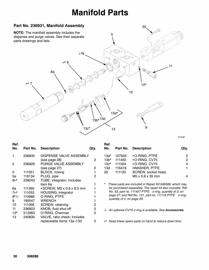
Manifold PartsPart No. 236931, Manifold Assembly
NOTE: The manifold assembly includes thedispense and purge valves. See their separateparts drawings and lists.
n 7
n 6
l*8
5
12*
11
9
10
13c*
01916F
6a
13b*
13a*
20
13
13d
Ref.No. Part No. Description Qty.
Ref.No. Part No. Description Qty.
1 236930 DISPENSE VALVE ASSEMBLY(see page 28) 2
2 236929 PURGE VALVE ASSEMBLY(see page 27) 2
5 111051 BLOCK, mixing 15a 116134 PLUG, pipe 26n 238243 TUBE, integrator; Includes
item 6a 16a 111260 SSCREW, M5 x 0.8 x 8.0 mm 17n 111053 HOUSING, integrator 18*l 110966 O-RING, PTFE 19 190047 WRENCH 110 111058 SCREW, retaining 211 236923 KNOB, fluid shut-off 212* 512063 O-RING, Chemraz 213 240830 VALVE, ratio check; Includes
replaceable items 13a--13d 2
13a* 107505 SO-RING, PTFE 213b* 111450 SO-RING, CV75 213c* 111504 SO-RING, CV75 413d 116416 SWASHER, PTFE 120 111120 SCREW, socket head;
M5 x 0.8 x 35 mm 4
* These parts are included in Repair Kit 948588, which maybe purchased separately. The repair kit also includes: RefNo. 53, part no. 111457 PTFE o-ring, quantity of 2, onpage 27; and Ref No. 131, part no. 111116 PTFE o-ring,quantity of 4, on page 29.
l An optional CV75 o-ring is available. See Accessories.
n Keep these spare parts on hand to reduce down time.
308288 31
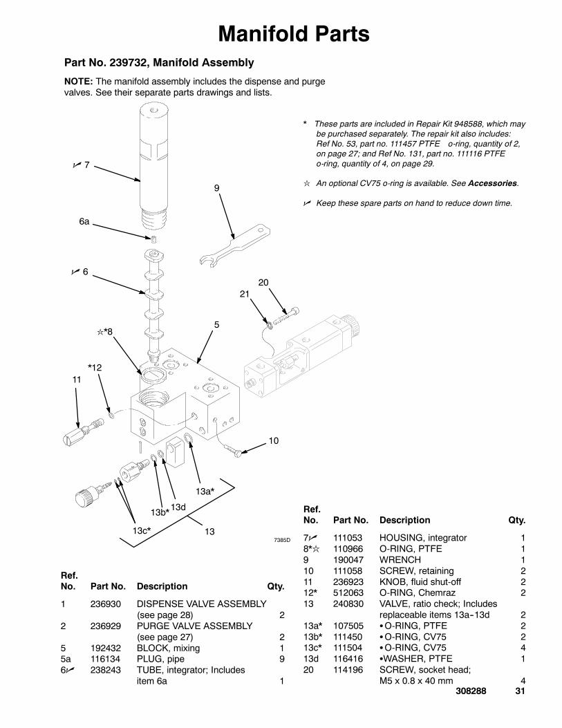
Manifold PartsPart No. 239732, Manifold Assembly
NOTE: The manifold assembly includes the dispense and purgevalves. See their separate parts drawings and lists.
* These parts are included in Repair Kit 948588, which maybe purchased separately. The repair kit also includes:Ref No. 53, part no. 111457 PTFE o-ring, quantity of 2,on page 27; and Ref No. 131, part no. 111116 PTFEo-ring, quantity of 4, on page 29.
l An optional CV75 o-ring is available. See Accessories.
n Keep these spare parts on hand to reduce down time.
Ref.No. Part No. Description Qty.
1 236930 DISPENSE VALVE ASSEMBLY(see page 28) 2
2 236929 PURGE VALVE ASSEMBLY(see page 27) 2
5 192432 BLOCK, mixing 15a 116134 PLUG, pipe 96n 238243 TUBE, integrator; Includes
item 6a 1
Ref.No. Part No. Description Qty.
7n 111053 HOUSING, integrator 18*l 110966 O-RING, PTFE 19 190047 WRENCH 110 111058 SCREW, retaining 211 236923 KNOB, fluid shut-off 212* 512063 O-RING, Chemraz 213 240830 VALVE, ratio check; Includes
replaceable items 13a--13d 213a* 107505 SO-RING, PTFE 213b* 111450 SO-RING, CV75 213c* 111504 SO-RING, CV75 413d 116416 SWASHER, PTFE 120 114196 SCREW, socket head;
M5 x 0.8 x 40 mm 4
n 7
n 6
l*85
*1211
10
13c*
6a
13b*
13a*
7385D
9
2120
13
13d
* These parts are included in Repair Kit 948588, which maybe purchased separately. The repair kit also includes:Ref No. 53, part no. 111457 PTFE o-ring, quantity of 2,on page 27; and Ref No. 131, part no. 111116 PTFEo-ring, quantity of 4, on page 29.
l An optional CV75 o-ring is available. See Accessories.
n Keep these spare parts on hand to reduce down time.
TI0173B
5
*1211
10
13c*13b*
13a*
2120
13
12
20
4
14
3
27
n6
6a
27
n7
13d
5a
32 308288
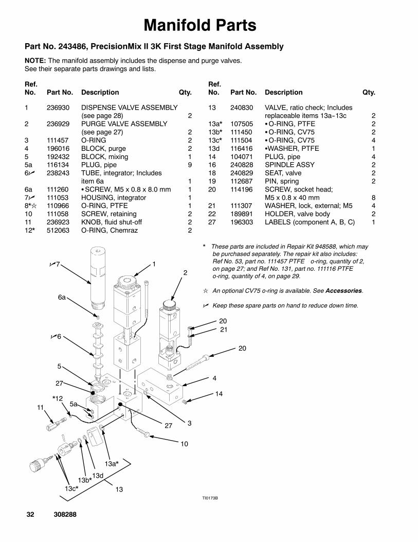
Manifold PartsPart No. 243486, PrecisionMix II 3K First Stage Manifold Assembly
NOTE: The manifold assembly includes the dispense and purge valves.See their separate parts drawings and lists.
Ref.No. Part No. Description Qty.
Ref.No. Part No. Description Qty.
1 236930 DISPENSE VALVE ASSEMBLY(see page 28) 2
2 236929 PURGE VALVE ASSEMBLY(see page 27) 2
3 111457 O-RING 24 196016 BLOCK, purge 25 192432 BLOCK, mixing 15a 116134 PLUG, pipe 96n 238243 TUBE, integrator; Includes
item 6a 16a 111260 SSCREW, M5 x 0.8 x 8.0 mm 17n 111053 HOUSING, integrator 18*l 110966 O-RING, PTFE 110 111058 SCREW, retaining 211 236923 KNOB, fluid shut-off 212* 512063 O-RING, Chemraz 2
13 240830 VALVE, ratio check; Includesreplaceable items 13a--13c 2
13a* 107505 SO-RING, PTFE 213b* 111450 SO-RING, CV75 213c* 111504 SO-RING, CV75 413d 116416 SWASHER, PTFE 114 104071 PLUG, pipe 416 240828 SPINDLE ASSY 218 240829 SEAT, valve 219 112687 PIN, spring 220 114196 SCREW, socket head;
M5 x 0.8 x 40 mm 821 111307 WASHER, lock, external; M5 422 189891 HOLDER, valve body 227 196303 LABELS (component A, B, C) 1
308288 33
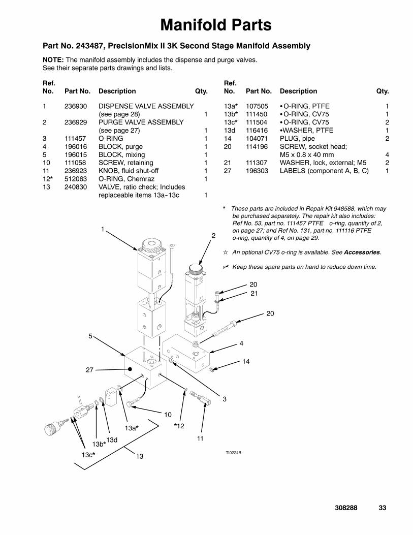
Manifold PartsPart No. 243487, PrecisionMix II 3K Second Stage Manifold Assembly
NOTE: The manifold assembly includes the dispense and purge valves.See their separate parts drawings and lists.
Ref.No. Part No. Description Qty.
Ref.No. Part No. Description Qty.
1 236930 DISPENSE VALVE ASSEMBLY(see page 28) 1
2 236929 PURGE VALVE ASSEMBLY(see page 27) 1
3 111457 O-RING 14 196016 BLOCK, purge 15 196015 BLOCK, mixing 110 111058 SCREW, retaining 111 236923 KNOB, fluid shut-off 112* 512063 O-RING, Chemraz 113 240830 VALVE, ratio check; Includes
replaceable items 13a--13c 1
13a* 107505 SO-RING, PTFE 113b* 111450 SO-RING, CV75 113c* 111504 SO-RING, CV75 213d 116416 SWASHER, PTFE 114 104071 PLUG, pipe 220 114196 SCREW, socket head;
M5 x 0.8 x 40 mm 421 111307 WASHER, lock, external; M5 227 196303 LABELS (component A, B, C) 1
* These parts are included in Repair Kit 948588, which maybe purchased separately. The repair kit also includes:Ref No. 53, part no. 111457 PTFE o-ring, quantity of 2,on page 27; and Ref No. 131, part no. 111116 PTFEo-ring, quantity of 4, on page 29.
l An optional CV75 o-ring is available. See Accessories.
n Keep these spare parts on hand to reduce down time.
5
*12
11
10
13c*
13b*
13a*
2120
13TI0224B
12
20
4
14
3
27
13d
34 308288
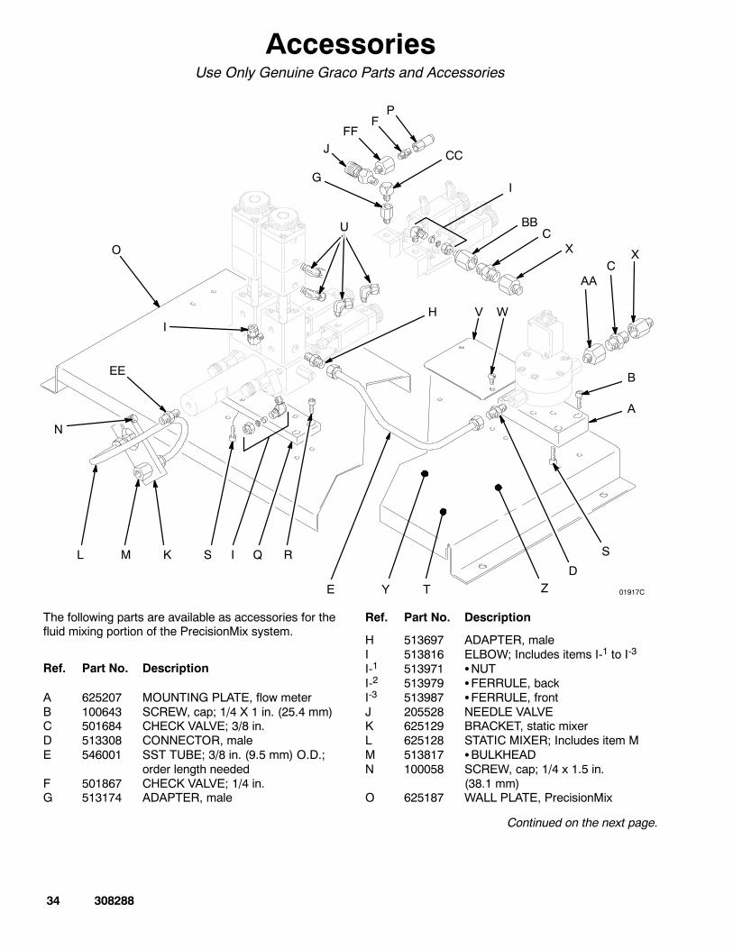
AccessoriesUse Only Genuine Graco Parts and Accessories
01917C
PF
J
I
CXO
I
N
L M K S Q
H
R
TY Z
V W
E
S
D
AAC
X
B
A
G
CC
BB
I
U
EE
FF
The following parts are available as accessories for thefluid mixing portion of the PrecisionMix system.
Ref. Part No. Description
A 625207 MOUNTING PLATE, flow meterB 100643 SCREW, cap; 1/4 X 1 in. (25.4 mm)C 501684 CHECK VALVE; 3/8 in.D 513308 CONNECTOR, maleE 546001 SST TUBE; 3/8 in. (9.5 mm) O.D.;
order length neededF 501867 CHECK VALVE; 1/4 in.G 513174 ADAPTER, male
Ref. Part No. Description
H 513697 ADAPTER, maleI 513816 ELBOW; Includes items I-1 to I-3
I-1 513971 SNUTI-2 513979 SFERRULE, backI-3 513987 SFERRULE, frontJ 205528 NEEDLE VALVEK 625129 BRACKET, static mixerL 625128 STATIC MIXER; Includes item MM 513817 SBULKHEADN 100058 SCREW, cap; 1/4 x 1.5 in.
(38.1 mm)O 625187 WALL PLATE, PrecisionMix
Continued on the next page.
308288 35
AccessoriesUse Only Genuine Graco Parts and Accessories
NOTE: See the drawing on the previous page.
Ref.No. Part No. Description
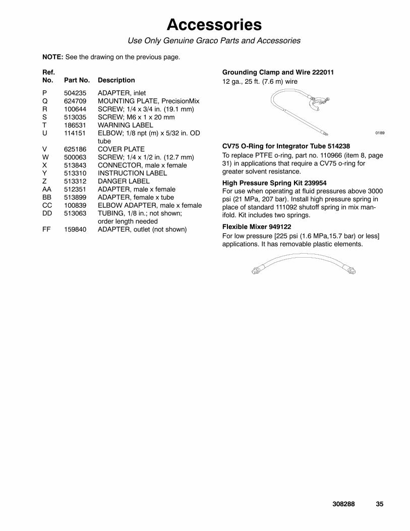
P 504235 ADAPTER, inletQ 624709 MOUNTING PLATE, PrecisionMixR 100644 SCREW; 1/4 x 3/4 in. (19.1 mm)S 513035 SCREW; M6 x 1 x 20 mmT 186531 WARNING LABELU 114151 ELBOW; 1/8 npt (m) x 5/32 in. OD
tubeV 625186 COVER PLATEW 500063 SCREW; 1/4 x 1/2 in. (12.7 mm)X 513843 CONNECTOR, male x femaleY 513310 INSTRUCTION LABELZ 513312 DANGER LABELAA 512351 ADAPTER, male x femaleBB 513899 ADAPTER, female x tubeCC 100839 ELBOW ADAPTER, male x femaleDD 513063 TUBING, 1/8 in.; not shown;
order length neededFF 159840 ADAPTER, outlet (not shown)
Grounding Clamp and Wire 22201112 ga., 25 ft. (7.6 m) wire
0189
CV75 O-Ring for Integrator Tube 514238To replace PTFE o-ring, part no. 110966 (item 8, page31) in applications that require a CV75 o-ring forgreater solvent resistance.
High Pressure Spring Kit 239954For use when operating at fluid pressures above 3000psi (21 MPa, 207 bar). Install high pressure spring inplace of standard 111092 shutoff spring in mix man-ifold. Kit includes two springs.
Flexible Mixer 949122For low pressure [225 psi (1.6 MPa,15.7 bar) or less]applications. It has removable plastic elements.
36 308288
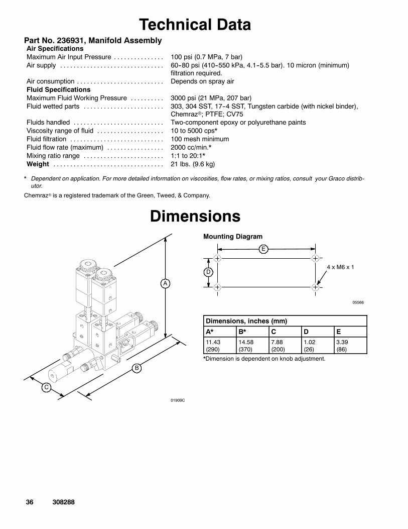
Technical DataPart No. 236931, Manifold AssemblyAir SpecificationsMaximum Air Input Pressure . . . . . . . . . . . . . . . 100 psi (0.7 MPa, 7 bar)Air supply . . . . . . . . . . . . . . . . . . . . . . . . . . . . . . . 60--80 psi (410--550 kPa, 4.1--5.5 bar). 10 micron (minimum)
filtration required.Air consumption . . . . . . . . . . . . . . . . . . . . . . . . . . Depends on spray airFluid SpecificationsMaximum Fluid Working Pressure . . . . . . . . . . 3000 psi (21 MPa, 207 bar)Fluid wetted parts . . . . . . . . . . . . . . . . . . . . . . . . 303, 304 SST, 17--4 SST, Tungsten carbide (with nickel binder),
Chemrazr; PTFE; CV75Fluids handled . . . . . . . . . . . . . . . . . . . . . . . . . . . Two-component epoxy or polyurethane paintsViscosity range of fluid . . . . . . . . . . . . . . . . . . . . 10 to 5000 cps*Fluid filtration . . . . . . . . . . . . . . . . . . . . . . . . . . . . 100 mesh minimumFluid flow rate (maximum) . . . . . . . . . . . . . . . . . 2000 cc/min.*Mixing ratio range . . . . . . . . . . . . . . . . . . . . . . . . 1:1 to 20:1*Weight . . . . . . . . . . . . . . . . . . . . . . . . . . . . . . . . . 21 lbs. (9.6 kg)
* Dependent on application. For more detailed information on viscosities, flow rates, or mixing ratios, consult your Graco distrib-utor.
Chemrazr is a registered trademark of the Green, Tweed, & Company.
Dimensions
01909C
A
B
C
Mounting Diagram
05566
D
E
4 x M6 x 1
Dimensions, inches (mm)
A* B* C D E11.43(290)
14.58(370)
7.88(200)
1.02(26)
3.39(86)
*Dimension is dependent on knob adjustment.
308288 37
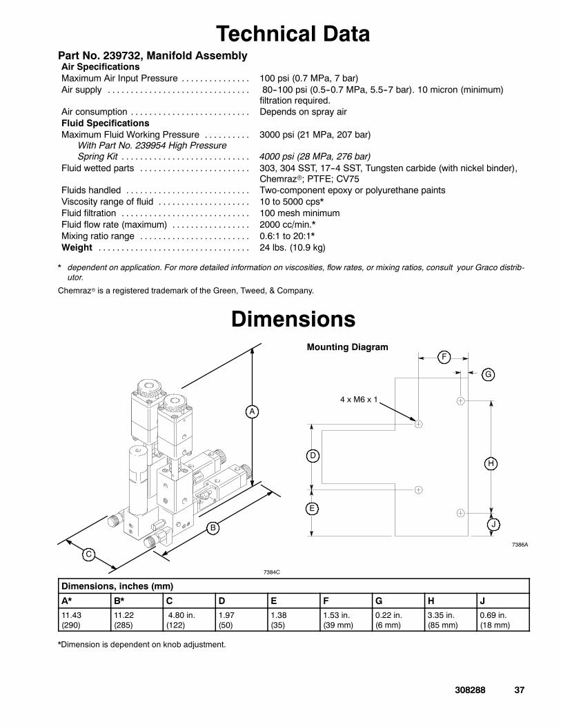
Technical DataPart No. 239732, Manifold AssemblyAir SpecificationsMaximum Air Input Pressure . . . . . . . . . . . . . . . 100 psi (0.7 MPa, 7 bar)Air supply . . . . . . . . . . . . . . . . . . . . . . . . . . . . . . . 80--100 psi (0.5--0.7 MPa, 5.5--7 bar). 10 micron (minimum)
filtration required.Air consumption . . . . . . . . . . . . . . . . . . . . . . . . . . Depends on spray airFluid SpecificationsMaximum Fluid Working Pressure . . . . . . . . . .
With Part No. 239954 High PressureSpring Kit . . . . . . . . . . . . . . . . . . . . . . . . . . . .
3000 psi (21 MPa, 207 bar)
4000 psi (28 MPa, 276 bar)Fluid wetted parts . . . . . . . . . . . . . . . . . . . . . . . . 303, 304 SST, 17--4 SST, Tungsten carbide (with nickel binder),
Chemrazr; PTFE; CV75Fluids handled . . . . . . . . . . . . . . . . . . . . . . . . . . . Two-component epoxy or polyurethane paintsViscosity range of fluid . . . . . . . . . . . . . . . . . . . . 10 to 5000 cps*Fluid filtration . . . . . . . . . . . . . . . . . . . . . . . . . . . . 100 mesh minimumFluid flow rate (maximum) . . . . . . . . . . . . . . . . . 2000 cc/min.*Mixing ratio range . . . . . . . . . . . . . . . . . . . . . . . . 0.6:1 to 20:1*Weight . . . . . . . . . . . . . . . . . . . . . . . . . . . . . . . . . 24 lbs. (10.9 kg)
* dependent on application. For more detailed information on viscosities, flow rates, or mixing ratios, consult your Graco distrib-utor.
Chemrazr is a registered trademark of the Green, Tweed, & Company.
Dimensions
A
B
C
7384C
4 x M6 x 1
7386A
D
E
F
G
H
J
Mounting Diagram
Dimensions, inches (mm)
A* B* C D E F G H J11.43(290)
11.22(285)
4.80 in.(122)
1.97(50)
1.38(35)
1.53 in.(39 mm)
0.22 in.(6 mm)
3.35 in.(85 mm)
0.69 in.(18 mm)
*Dimension is dependent on knob adjustment.
38 308288
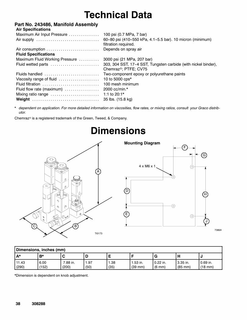
Technical DataPart No. 243486, Manifold AssemblyAir SpecificationsMaximum Air Input Pressure . . . . . . . . . . . . . . . 100 psi (0.7 MPa, 7 bar)Air supply . . . . . . . . . . . . . . . . . . . . . . . . . . . . . . . 60--80 psi (410--550 kPa, 4.1--5.5 bar). 10 micron (minimum)
filtration required.Air consumption . . . . . . . . . . . . . . . . . . . . . . . . . . Depends on spray airFluid SpecificationsMaximum Fluid Working Pressure . . . . . . . . . . 3000 psi (21 MPa, 207 bar)Fluid wetted parts . . . . . . . . . . . . . . . . . . . . . . . . 303, 304 SST, 17--4 SST, Tungsten carbide (with nickel binder),
Chemrazr; PTFE; CV75Fluids handled . . . . . . . . . . . . . . . . . . . . . . . . . . . Two-component epoxy or polyurethane paintsViscosity range of fluid . . . . . . . . . . . . . . . . . . . . 10 to 5000 cps*Fluid filtration . . . . . . . . . . . . . . . . . . . . . . . . . . . . 100 mesh minimumFluid flow rate (maximum) . . . . . . . . . . . . . . . . . 2000 cc/min.*Mixing ratio range . . . . . . . . . . . . . . . . . . . . . . . . 1:1 to 20:1*Weight . . . . . . . . . . . . . . . . . . . . . . . . . . . . . . . . . 35 lbs. (15.8 kg)
* dependent on application. For more detailed information on viscosities, flow rates, or mixing ratios, consult your Graco distrib-utor.
Chemrazr is a registered trademark of the Green, Tweed, & Company.
Dimensions
A
BC
TI0173
4 x M6 x 1
7386A
D
E
F
G
H
J
Mounting Diagram
Dimensions, inches (mm)
A* B* C D E F G H J11.43(290)
6.00(152)
7.88 in.(200)
1.97(50)
1.38(35)
1.53 in.(39 mm)
0.22 in.(6 mm)
3.35 in.(85 mm)
0.69 in.(18 mm)
*Dimension is dependent on knob adjustment.
308288 39
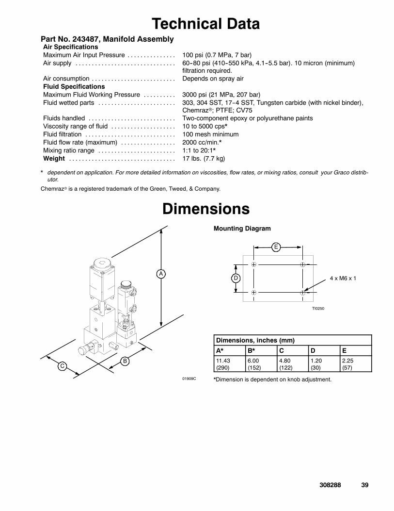
Technical DataPart No. 243487, Manifold AssemblyAir SpecificationsMaximum Air Input Pressure . . . . . . . . . . . . . . . 100 psi (0.7 MPa, 7 bar)Air supply . . . . . . . . . . . . . . . . . . . . . . . . . . . . . . . 60--80 psi (410--550 kPa, 4.1--5.5 bar). 10 micron (minimum)
filtration required.Air consumption . . . . . . . . . . . . . . . . . . . . . . . . . . Depends on spray airFluid SpecificationsMaximum Fluid Working Pressure . . . . . . . . . . 3000 psi (21 MPa, 207 bar)Fluid wetted parts . . . . . . . . . . . . . . . . . . . . . . . . 303, 304 SST, 17--4 SST, Tungsten carbide (with nickel binder),
Chemrazr; PTFE; CV75Fluids handled . . . . . . . . . . . . . . . . . . . . . . . . . . . Two-component epoxy or polyurethane paintsViscosity range of fluid . . . . . . . . . . . . . . . . . . . . 10 to 5000 cps*Fluid filtration . . . . . . . . . . . . . . . . . . . . . . . . . . . . 100 mesh minimumFluid flow rate (maximum) . . . . . . . . . . . . . . . . . 2000 cc/min.*Mixing ratio range . . . . . . . . . . . . . . . . . . . . . . . . 1:1 to 20:1*Weight . . . . . . . . . . . . . . . . . . . . . . . . . . . . . . . . . 17 lbs. (7.7 kg)
* dependent on application. For more detailed information on viscosities, flow rates, or mixing ratios, consult your Graco distrib-utor.
Chemrazr is a registered trademark of the Green, Tweed, & Company.
Dimensions
01909C
A
BC
Mounting Diagram
TI0250
D
E
4 x M6 x 1
Dimensions, inches (mm)
A* B* C D E11.43(290)
6.00(152)
4.80(122)
1.20(30)
2.25(57)
*Dimension is dependent on knob adjustment.
40 308288
Graco Standard WarrantyGraco warrants all equipment referenced in this document which is manufactured by Graco and bearing its name to be free fromdefects in material and workmanship on the date of sale to the original purchaser for use. With the exception of any special, extended,or limited warranty published by Graco, Graco will, for a period of twelve months from the date of sale, repair or replace any part of theequipment determined byGraco to be defective. This warranty applies only when the equipment is installed, operated andmaintainedin accordance with Graco’s written recommendations.
This warranty does not cover, and Graco shall not be liable for general wear and tear, or any malfunction, damage or wear caused byfaulty installation,misapplication, abrasion, corrosion, inadequate or impropermaintenance, negligence, accident, tampering, or sub-stitution of non--Graco component parts. Nor shall Graco be liable for malfunction, damage or wear caused by the incompatibility ofGraco equipment with structures, accessories, equipment or materials not supplied by Graco, or the improper design, manufacture,installation, operation or maintenance of structures, accessories, equipment or materials not supplied by Graco.
This warranty is conditioned upon the prepaid return of the equipment claimed to be defective to an authorized Graco distributor forverification of the claimed defect. If the claimed defect is verified, Graco will repair or replace free of charge any defective parts. Theequipmentwill be returned to the original purchaser transportation prepaid. If inspection of the equipment does notdisclose anydefectin material or workmanship, repairs will be made at a reasonable charge, which charges may include the costs of parts, labor, andtransportation.
THIS WARRANTY IS EXCLUSIVE, AND IS IN LIEU OF ANY OTHER WARRANTIES, EXPRESS OR IMPLIED, INCLUDING BUTNOT LIMITED TO WARRANTY OF MERCHANTABILITY OR WARRANTY OF FITNESS FOR A PARTICULAR PURPOSE.
Graco’s sole obligation and buyer’s sole remedy for any breach of warranty shall be as set forth above. The buyer agrees that no otherremedy (including, but not limited to, incidental or consequential damages for lost profits, lost sales, injury to person or property, or anyother incidental or consequential loss) shall be available. Any action for breach of warrantymust be brought within two (2) years of thedate of sale.
GRACOMAKES NOWARRANTY, ANDDISCLAIMS ALL IMPLIEDWARRANTIESOF MERCHANTABILITY AND FITNESS FORA PARTICULAR PURPOSE, IN CONNECTION WITH ACCESSORIES, EQUIPMENT, MATERIALS OR COMPONENTS SOLDBUT NOT MANUFACTURED BY GRACO. These items sold, but not manufactured by Graco (such as electric motors, switches,hose, etc.), are subject to the warranty, if any, of their manufacturer. Graco will provide purchaser with reasonable assistance in mak-ing any claim for breach of these warranties.
In no event will Graco be liable for indirect, incidental, special or consequential damages resulting from Graco supplying equipmenthereunder, or the furnishing, performance, or use of any products or other goods sold hereto, whether due to a breach of contract,breach of warranty, the negligence of Graco, or otherwise.
FOR GRACO CANADA CUSTOMERSThe parties acknowledge that they have required that the present document, as well as all documents, notices and legal proceedingsentered into, given or instituted pursuant hereto or relating directly or indirectly hereto, be drawn up in English. Les parties reconnais-sent avoir convenu que la rédaction du présente document sera en Anglais, ainsi que tous documents, avis et procédures judiciairesexécutés, donnés ou intentés à la suite de ou en rapport, directement ou indirectement, avec les procedures concernées.
Graco InformationTO PLACE AN ORDER, contact your Graco distributor, or call one of these numbers
to identify the distributor closest to you:1--800--328--0211 Toll Free
612--623--6921612--378--3505 Fax
All written and visual data contained in this document reflects the latest product information available at the time of publication.Graco reserves the right to make changes at any time without notice.
MM 308288
Graco Headquarters: MinneapolisInternational Offices: Belgium, China, Japan, Korea
GRACO INC. P.O. BOX 1441 MINNEAPOLIS, MN 55440--1441www.graco.com
PRINTED IN U.S.A. 308288 09/1993 Revised 11/2005