305–1987 seminars some current developments aust pipe industry
DESCRIPTION
305–1987 Seminars Some Current Developments Aust Pipe IndustryTRANSCRIPT

www.cpaa.asn.auConcrete Pipe Associationof Australasia
Some CurrentDevelopments in theAustralian Pipe Industry
Papers by:Dr. Norwood L. HarrisonMr. Allan GugerDr. Michael A. Peck

1987 Seminars
Concrete PipeAssociationof Australia
,,
Some CurrentDevelopments in the iJ
Australian Pipe Industry
Papers by:Dr. Norwood L. HarrisonMr. Allan GugerDr. Michael A. Peck
The information contained in these notes has been prepared for the guidance of those attending the Seminar. It isnot to be regarded as complete within itself and should not therefore. be used without independent examination andverification of its suitability for a particular project. Anyone making use of the information or material contained hereindoes so at their own risk and assumes any and all liability from such use.
The notes shall not be reproduced without the consent of the CPAA and then only in full.

Dr. N. L. Harrison, B.Se., PhD,Manager, Westall R&D, Humes Concrete.
After graduating from the University of Queensland in 1964, Dr. Harrisonworked at English Electric in the U.K. and subsequently obtained his PhD fromMonash University, in Materials Engineering. He joined Humes in 1971 andhas been Manager of the company's R&D Laboratories at Westall since 1975.
12th August, 1987
ASPECTS OF BEDDING RIGID & FLEXIBLE PIPES
INTRODUCTION
Civil engineering structures inevitably depend on thecharacteristics of earth materials as well as of themanufactured components. To quote from Spangler (Ref. 1),"All structures, regardless of the material of which theyare constructed, rest ultimately upon sailor rock ... Inthe case of sewers, culverts, tunnels, and other types ofunderground structures, .... soil is important not onlyas the material upon which the structures are found~d, butalso as the major source of the loads to which they' aresUbjected in service and which they must be designed tocarry." The aim of structural design of pipelines is tocreate a stable interaction between the pipes and thesurrounding soil, in which the pipe shape remains at leastapproximately circular. Australian Standards dealing withpipeline installation contain a wealth of detail, but ineach case the design calculation is clearly targeted atavoiding a specific unacceptable condition:
AS CA 33-1962, "Concrete Pipelaying Design" - the LOAD onthe pipe is limited to its proof load multiplied by a factorcorresponding to the type of bedding; i.e. the designprocedure guards against overloading the pipe.
AS 2042-1984, "Corrugated Steel Pipes, Pipe-arches, andArches - Design and Installation" - the design limits theCOMPRESSIVE STRESS IN THE PIPE WALL to a value which thepipe is designed to carry.
AS 2566-1982, "Plastics Pipelaying Design" - the designlimits the DEFLECTION of the pipe (change in diameter) to 5%.
s ~
The first section of this paper deals with technologydevelopment in the field of design, laying and bedding ofconcrete pipe leading to the revision of the concrete pipelaying code, CA 33. These established laying practices forrigid (concrete) pipe are then compared and contrasted withflexible pipe installation practices, where it appears thatcodes are not specific, definitions are confusing,technology is imprecise and laying procedures neitherstandardised nor subject to long term verification.
RIGID PIPE
Design of concrete pipe installati~ns is at present coveredby Australian Standard CA 33-1962, Concrete Pipe LayingDesign. While this code is intended primarily for concretepipes, it "may also be used for the calculation of loads onother rigid pipes".
2
The revision of CA 33
CA 33 is based on the original work of Marston and Spangler.It specifies how loads on buried pipes are to be calculated,and defines a number of standard bedding conditions. A"load factor" (in the revised Standard referred to as a"bedding factor") is ascribed to each of the standardbeddings, determined by the extent to which the beddingredistributes the stress in the pipe. The serviceabilityof concrete pipes is established by a three-edge bearingtest ensuring that they are capable of meeting fieldstructural requirements - experience has shown that, becauseconcrete strength does not degrade, compliance with aninitial test requirement will ensure serviceability.
SinGe the original Spangler analysis, much research intoloads on buried concrete pipes has been performed in theUSA, Australia and elsewhere. This research has basicallybeen directed at studying field loads on pipes under avariety of bedding conditions - the best known of theseprobably being the "Mountainhouse Creek" tests conducted inthe 1970's by the Californian Department of Transportation,where several bedding types were tested under fill heightsup to 41 metres. Best performances were obtained when thepipes were laid in a trench excavated into the foundationmaterial beneath the embankment, the trench being laterbackfilled with compacted fine crushed rock. This systemhas become known as "CALTRANS" bedding (Ref. 2.). Theresearch also indicated that no benefit is galned byshaping the bedding beneath the pipe to fit the pipe'scurvature.
Amer~can research is continuing, partly sponsored throughthe American Concrete Pipe Association which, in conjunctionwith Frank Heger and Associates is studying a designanalysis process known as SPIDA (Soil-Pipe-InteractionDesign Analysis). It is likely that the results of thiswork, still some 12 months or more away from completion,could further influence Australian Codes - preliminaryindications show our revision to be still reasonablyconservative.
During the revision of CA 33 it was decided by the CPAA andSAA Committee WS/6 to obtain an independent Australianverification of the American results using the more slenderAustralian pipes. This work was carried out by Mr. S. Costinon behalf of the CPAA, under the direction of Dr. Neil Kayat the University of Adelaide (Ref. 3).

3
Two aspects were studied:
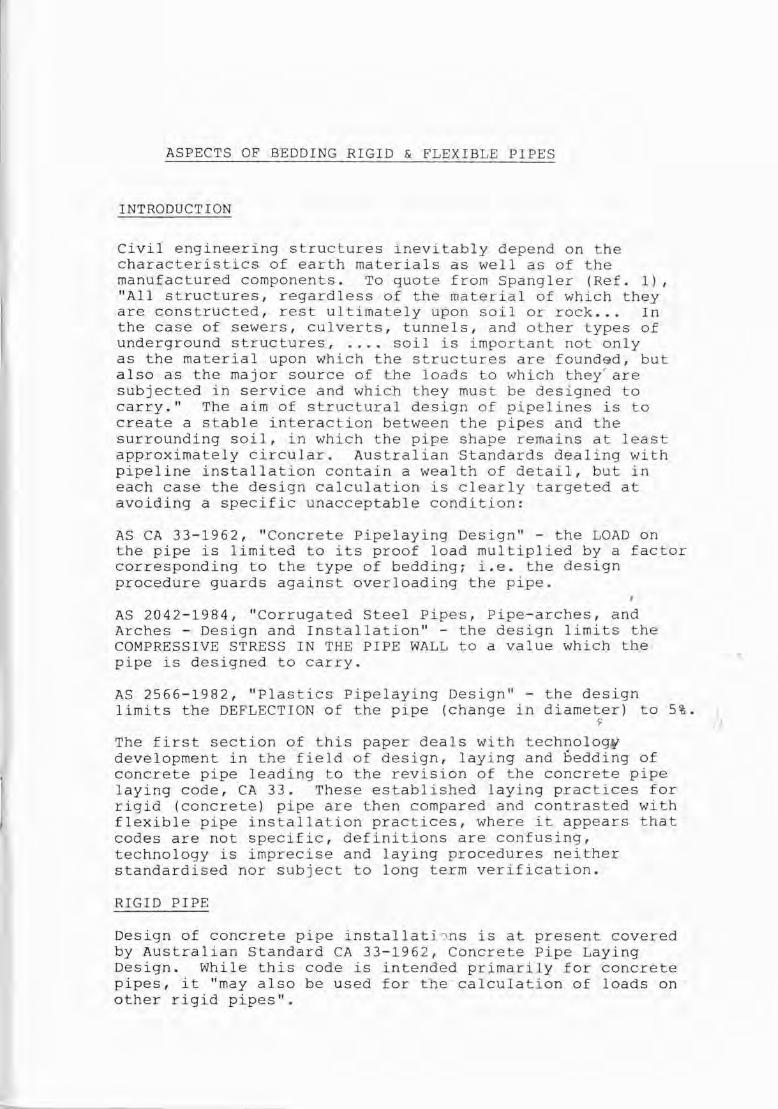
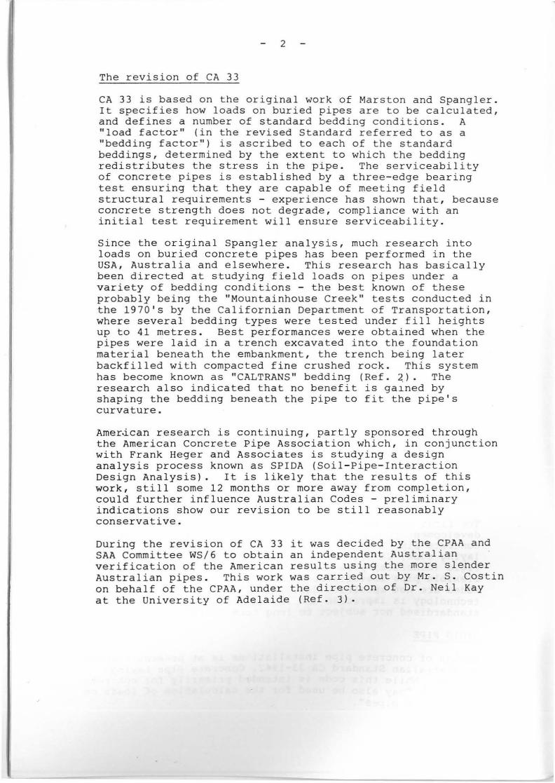
a) In a simulated inground situation, the degree ofcompaction of backfill achieved around the pipe wasmeasured by density tests. As is shown in Figs .. 1 and 2,compaction was quite variable and tapered off below about30 degrees under the haunch on each side, in spite of thefact that every effort was made with a vibrating compactorto push as much of the material as possible under the pipe.
b) An investigation by measurement and theoretical analysisof maximum fill height was carried out in a test bin whichenabled simulation of embankment loads - see Fig. 3.Concrete pipe was laid in a compacted quarry rubble trench,bedded on quarry sand and finally covered with rained sand.A rubber bag was used to apply uniform load. The beddingfactor calculated from this was 5.2, i.e. the bedde9 pipewould support 5.2 times as much vertical load as the pipewould under the three-edge bearing test. The new draftAustralian Standard has conservatively adopted a value of4 for a similar type of bedding.
The major changes in the CA 33 revision, apart from editing,metrication and the inclusion of an explanatory comment are:
- Deletion of references to shaped bedding.
- Introduction of a new series of standard beddings,nominated as GS1, GS2, and GS3 - and superseding the oldalphabetical series. (GS3 is similar to the CALTRANS system).
- More details of compaction and material specifications.
- Modified live load approach in accordance withrecommendations of the American Concrete Pipe Association.
- Determination of jacking pipe loads.
- An increased emphasis on induced trench construction ofculverts under high fills. ~ I
~
- Increased bedding factors up to 4 for bedding for thehighest grade system - GS3 bedding - the 1962 maximumbeing less than 3 for granular type beddings.
The significance of these changes is:
- It brings the code in line with modern technology andpractice.
- It formalises the ability of steel reinforced concretepipe to perform in significantly higher embankmentconditions than previously allowed.
- It offers designers a choice of bedding condition andpipe class on a clearly understood and scientific basis,thus enabling a proper consideration of economics.

4
Determination of Test Loads
Clause 5 of CA 33 specified the method for calculating pipetest loads. For reinforced concrete pipe, the test load,meaning the proof or "cracking" load, is equal to theimposed load divided by the bedding factor. Ultimate loads(AS 1342) are of course 1.5 times the cracking loads. Fornon-reinforced concrete pipe, the test (ultimate) loadis the imposed load divided by the bedding factor for theparticular class of bedding and then multiplied by 1.5.The purpose of these provisions is to provide a safetyfactor of 1.5 between the loads imposed in service and thepipe strength.
Provisions are essentially the same in the CA 33 revision.
This method of calculation clearly makes no allowance forany loss of pipe strength with time - indeed, for nonreinforced concrete pipe, the factor of safety will increasewith time as the pipe becomes stronger with progressivecuring.
The safety factor of 1.5 is applied in the same way tovitrified clay pipe installations.
It is recognised that strength properties of plasticsdiminish with time and provision is made in the design andtesting of plastics pipes for these changes. The introductionof cellulose FRC pipe, whose strength (like the strength ofplastics) diminishes with time, creates a situation amongrigid pipe materials for which CA 33 makes no provision.FRC pipes have been classified by their manufacturer asX, T, and Z, like concrete and vitrified clay pipes, but thetest loads set for these pipes (three times the designloads) do not give equivalent long term strength. This isillustrated in Fig. 4, showing that the long term strengthof FRC pipe resulting from the short-term testing requirementis two thirds or less of the long term strengths ofreinforced concrete or vitrified clay pipe of thecorresponding classifications. It takes a Class Y orClass Z FRC pipe (depending on the allowance made forstrength loss) to have equivalent long term strength to aClass X reinforced concrete or vitrified clay pipe.
FLEXIBLE PIPE
Pipe Stiffness
Pipes described as "flexible" are (typically) unable tosupport, by their own strength, more than a small fractionof the imposed load - see Fig. 5.
The Australian Standards for concrete pipe and corrugated metalpipe are explicit in their requirements relating to thestructural properties of the pipe itself. The formula givenin AS 2566 (Plastics Pipelaying Design) for calculatingdeflection contains a term derived from pipe properties butin many circumstances the size of this term affects thecalculated deflection only marginally, a situation which hasfar-reaching consequences.

5
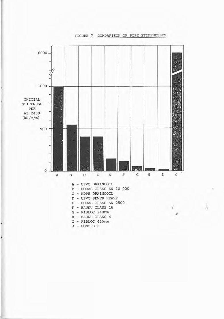
The shape which a flexible pipe takes up when it isinstalled is determined by the bedding and backfill andalso by a structural property of the pipe itself, referredto as its "stiffness". The effect of pipe stiffness on thedeflection calculated from AS 2566 is illustrated, for twotypical situations, in Fig. 6. Curve A corresponds to weaksoil, and indicates clearly how stiff the pipe must be tolimit the deflection to 5%. Curve B corresponds to verycommon situations of stiffer soils, in which THE DEFLECTIONIS LESS THAN 5% EVEN IF THE PIPE ITSELF HAS NEGLIGIBLESTIFFNESS. In such situations, the Standard gives norationale for choosing the correct stiffness for theconditions of installation. Pipes are being offered with awide range of stiffnesses (Fig. 7), and, as would beexpected, stiffer pipes tend to be more expensive.
To measure stiffness, pipe samples are loaded betweenparallel plates (which produces a similar effect on the pipeto the loading arrangement used for load testing cQhcretepipes). In the only current Australian Standard whichdefines pipe stiffness (AS 2439-1981, Perforated PlasticsDrainage Pipes), the stiffness is the load per metre of pipelength divided by the deflection.
Unfortunately, other measures are often used which aredefined in terms of the properties of the pipe wall ratherthan the measured behaviour of the pipe as a whole. It isimportant to understand which measure of pipe stiffness isbeing used, as the measure might be different even thoughthe units (eg Newtons per metre per metre) are the same.Figures 8 and 9 show how various measures of stiffness andclassifications based on them are related. Note that adifferent measure of stiffness is used for GRP (Hobas) fromthe ·measure used for spirally wound polyethylene (Bauku),even though both types of pipe are supplied by the samecompany. Both of these are different from the measure ofpipe stiffness in the Australian Standard.
Stiffness of plastic pipe in the long term is much less thanin the short term tests used for classifying the pipes.Bauku ("Black Brute ll
) loses a greater proportion o~f itsinitial stiffness in the long term than UPVC or Hobas pipe,but this is offset by classifying Bauku accordihg t~
stiffness measured after 24 hours' loading, rather thaninstantaneously. The long term stiffnesses of UPVC, Hobasand Bauku pipes are all about a third of the stiffnessmeasurements used to classify them.
Practical difficulties in installing flexible pipe
The first problem to be confronted with a flexible pipeinstallation is
THERE IS NO SINGLE RECOGNISED PROCEDURE FOR THE DESIGNCALCULATIONS. AS 2566 is apparently not considered adequatefor either Hobas, where the recommended alternative is ATV,or Bauku ("Black Brute"), where the laying instructionsmake no reference to AS 2566, ATV or any other code.
I
6
To quote from an Amerlcan source (K.K. Kienow) "The lackof adequate design technique for low stiffness pipe is oneof the best kept secrets of the plastic pipe industry today".
There are severe penalties from selecting wrong combinationsof pipe stiffness and bedding conditions, apart fromexcessive deflection:
- The pipe will deform into an irregular shape (Fig. 10).
- The pipe wall can crack or split (Fig. 11).
- Irregular deflections can cause joint leakage.
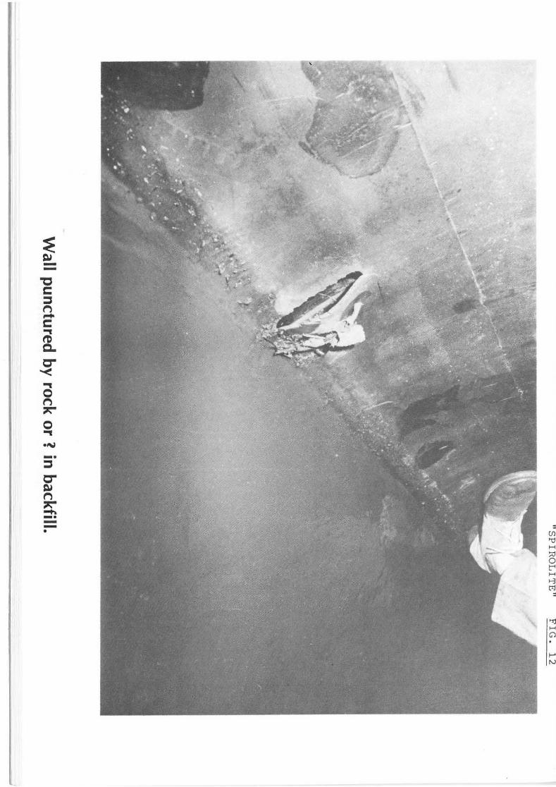
If the pipe is altogether too flimsy, rock or other hardinclusions in the backfill can puncture the wall (Fig. 12).
It is not our contention that flexible pipe will not performsatisfactorily if it is correctly designed and installed.The purpose of our comments is to highlight the uncertaintiesin these areas.
Installation Practices
As there is no comprehensive Australian Standard or Code forlaying flexible pipe it is not surprising that there is atremendous variation in the approach adopted by Authoritiesusing flexible pipe. However, it would appear that thespecifications issued by the N.S.W. P.W.D. cover most ofthe essentials, including
- penetrometer tests of the soil along the route the pipelineis to follow, to establish the soil stiffness,
- precautions to prevent the pipes floating before thetrench is backfilled,
- shading the pipes while they are above ground, to preventdistortion,
- use of special material for backfill (NATA tested forcompliance) ,
- in some circumstances, lining the trench with geotextile,
- further penetrometer tests to monitor the degree ofcompaction of backfilJ,
- monitoring pipe deflections at various stages during theirinstallation (this is particularly difficult with non-manentry sizes).
The other extreme is, quoting from a recent sewer tenderdocument;
"8.5.5 Information to be Supplied:

7
The Tenderer shall supply, within 7 days of a request to doso, in addition to the requirements outlined above, allinformation necessary to fully describe the pipes beingoffered. This information shall include but not belimited to the following:
- chemical and physical properties,
- dimensions and tolerances,
- standards of manufacture,
- bedding and surround design for different trench conditions,
- methods of jointing,
- recommended laying, handling and jointing proced~res,f
- proposed method of connection to pipes of other materialsand to manholes,
- evidence of a minimum 10 years of satisfactory serviceof the material under similar site conditions (includingsub-surface and temperature) for diameters 375 NB to 600 NB.
The information provided shall consist of all calculations,drawings, sketches and details that are necessary to provethe adequacy and suitability of the design. This informationshall be provided at no cost to the Principal."
Neither specification contains a stiffness criterion, noris there a field joint test of any practical significance the -joint should not be evaluated until the pipe is fullydeformed under the total soil load, and the 'long termdeformation has been essentially complete.
Installation Costs
In any cost comparison between rigid and flexible pipe, thebasis must be the in-ground cost of the completed project, /not just a comparison of pipe purchase costs. ~
Bedding flexible pipe is expensive.
Circumstances obviously will vary, but it may be of interestthat in a recent major sewer contract in which flexible pipewas used the contract figures were:
Supply of flexible pipe, $137/metre,
Laying/construction contract, $460/metre.

8
CONCLUSIONS
Concrete pipes manufactured, designed and installed inaccordance with Australian Standards covering every aspectof the product system have a proven field performance.The applicability of these pipes will be enhanced by thenew provisions of the CA 33 revision.
The classification of FRC pipe is inconsistent with theclassification of pipes made from concrete or vitrified clay.
There are inconsistencies in the classification of flexiblepipes which make it difficult for a specifier to comparealternative types.
Flexible pipe of adequate stiffness, high material qualityand properly bedded could be expected to performsatisfactorily except in unstable soils. However, the oneAustralian Standard dealing with installation of flexible(plastic) pipe is not considered to be adequate for alltypes, and there is no single, universally acceptedalternative.
Economic comparisons between rigid and flexible pipes mustbe made on the basis of in-ground costs.
REFERENCES
1. M.G. Spangler & R.L. Handy, "Soil Engineering", 4thEdition, 1982 (Harper & Rowe).
2. "Modern Pipelaying Techniques - High Fill Embankments 'The advantages of Low Projection and Induced TrendConstructions". Concrete pipe Association of Australia,October 1985.
3. S.A. Costin, "A Study of an Improved Installation Methodfor Reinforced Concrete Pipes under High Embankments",Department of Civil Engineering, University of Adelaide,April 1986.

Adelaide University Tests FIG. 1
Relativedensities
Sand
370 120 435 225
Fully Partially Loosecompacted compac ted
DENSITY HOLE LOCATIONS ANDMEASURED DENSITIES
II
Adelaide University Tests FIG.2
End view of trial bedding after removal of pipe, note exposed strip of fine aggregatebase not covered by sidefall.
\,..
..~.,-.:- "', ..
\~. 'I'
4'~t#'"
' ..., ..........
Note loose and irregular edge to fine crushed rick sidefill, imprint of plate load testvisible in centre of base.

Adelaide University Tests FIG.3
Maximum 171·1 kPa att ai ned
,,
Rained sand
170 432 432 170
Compactedfine crushed LO
0
rock <.D
Compacted~ quarry
Compacted sand rt.Jbble I'to ~.-(0
14 2000 -,-- 2000 ./
POSITION OF PIPE AND BEDDIN§.
IN TEST BIN

LONG TERM STRENGTHS OF PIPES, FROM CURRENT TESTING REQUIREMENTS
FIG. 4
Designloads forconcrete
.. Class Z ...Class Z --
Class YT1 Class Y
Class Z L T I Class Z
TI
clay XI I Class Y IClass Y I- Class X ! I .L... T
I
l I I I I IJ.Class X I- Class X ,..,
....
•Concrete Vitrified
Clay ..FRC
Notes: Upper and lower marks on the columns representing concretepipes are the ultimate and cracking loads respectively.
For FRC, upper mark is the claimed long term strength;lower mark is the projected long term strength fromAmdel sustained load testing and SAA DR 87090.
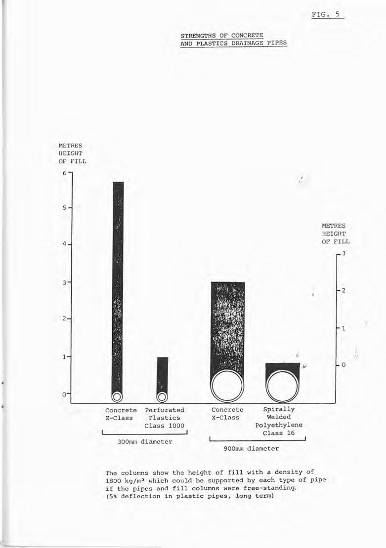
FIG. 5
STRENGTHS OF CONCRETEAND PLASTICS DRAINAGE PIPES
METRESHEIGHTOF FILL
METRESHEIGHTOF FILL
./
3
2
o
1
SpirallyWelded
polyethyleneClass 16
ConcreteX-Class
,,
PerforatedPlastics
Class 1000J
ConcreteZ-Class
3
6
4
5
2
a
1
300tnril diameter900nun diameter
The columns show the height of fill with a density of1800 kg/m 3 which could be supported by each type of pipeif the pipes and fill columns were free-standing.(5\ deflection in plastic pipes, long term)
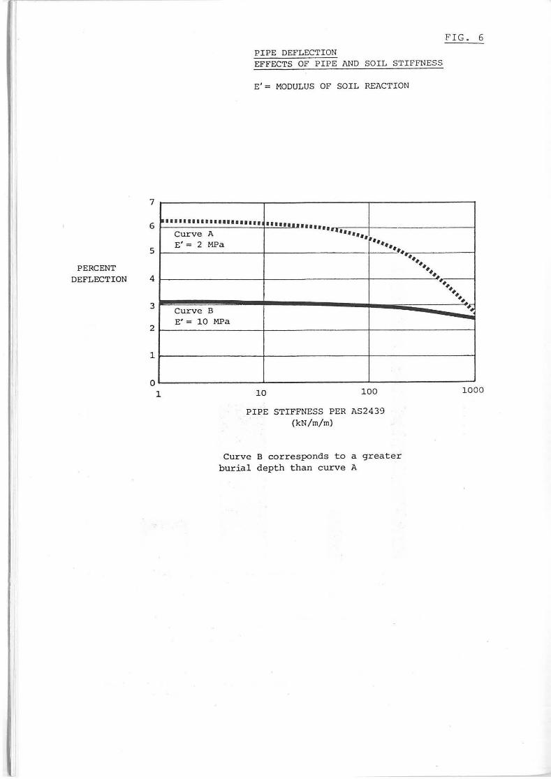
PIPE DEFLECTIONEFFECTS OF PIPE AND SOIL STIFFNESS
E'= MODULUS OF SOIL REACTION
FIG. 6
7
6
5
PERCENTDEFLECTION 4
3
2
1
~ ...................... •••••••••••••••Curve A ••••••• ," ","E'= 2 MPa III~
~-.#~
~##~##~
####
###
Curve B-##
E' = 10 MFa -o
1 10 100 1000
PIPE STIFFNESS PER AS2439(kN/m/m)
Curve B corresponds to a greaterburial depth than curve A
6000
1000
INITIALSTIFFNESS
PERAS 2439
(kN/m/m)
500
o
FIGURE 7 COMPARISON OF PIPE STIFFNESSES
A B C D E F G H I J
•
A - UPVC DRAINCOILB - HOBAS CLASS SN 10 000C - HDPE DRAINCOILD - UPVC SEWER HEAVYE - HOBAS CLASS SN 2500F - BAUKU CLASS 16G - RIBLOC 240mmH - BAUKU CLASS 4I - RIBLOC 465mmJ - CONCRETE

FIG. 8
RELATIVE STIFFNESSES OF FLEXIBLE PIPES
1CLASS 1 000
CLASS 10 000
CLASS 64
CLASS 400
BLACK BRUTE
CLASS 32
CLASS 16
CLASS B
CLASS 4
HOBAS
CLASS 5 000
CU\SS 200
CLASS 2 500
CLASS 100
AS 2439PERFORATED DRAINAGE PIPE

PIPE STIFFNESS
F(kN/m)
FIG. 9
~J6. y (m)
-r
,,
kN/m/m
LOAD/DEFLECTION(AS 2439)
FL::.y
S
PSEUDO ELASTIC EI SRFORMULAE R3
Sn ~ IIEl ,.,D3
•
S = 6.71 SR = 53.7 Sn•

r..n:::r~
"Ct"D
Ct"D~
t"Dn......
~
0......t"Dn:::r~~
()Q
:
t"D
(j)
'U
_.
H
~
::00
~
L'
-H
0
~
~
l:Ij:
-t"D<
t-Ij
t"D
H
-GJ
•
C
f-'0
.....II.",

•
I
iJ
~~--
"CC:::st"'),..C'""I
~0"""<'""Iot"')::r::-o'""I
.~_.:::s0""~t"')::r::-tt._.--•
•
•
,,
Performance of Pipe Materialsby
Mr. Allan Guger

Mr. A. Guger,Technical Services Manager,Monier Rocla,Pipe and Precast Division
QualificationsBachelor of Science, University of Saskatchewan, Canada.Master of Science - Structural Engineering,
University of Calgary, Alberta, Canada.
Affiliations- WS 10 Flexible Jointing Gaskets Committee.- CPAA Technical Committee.- Construction Materials Testing Group - NATA
ExperienceSixteen years with Monier Rocla in the development of products and testing ofmaterials. The last four years as the Manager of the Research Centre. For thelast one and one-half years he has been Technical Services Manager.

PERFPIPE.HAGPerformance of Pipe Materia s
1. Introduction
The development of conduits for the transportation of waterhad its beginning over 5000 years ago. The mater ials usedin the construction of the pipes were clay, stone andcellulose type materials such as wooden logs and bamboo.These three materials are still in current use but in aslightly different form.
Today there are a number of materials availab~e from whichthe designer can choose. Materials which are presentlybeing used are steel reinforced concrete, ductile iron,vitrified clay, cellulose reinforced fibre, steel andplastics. The plastic material is expanding and now covershigh density polyethylene, (HDPE) medium densitypolyethylene (MDPE), unplasticized polyvinyl Chloride(uPVC) . In addi tion, there is glass reinforced plastics(GRP) which can be formed with chopped fibreglass strand orf i lamen t wound strand. Two products which have not bee;nmentioned are cast iron and asbestos reinforced pipe. Themanufacture of these pipes have been discontinued, eventhough the products have had creditable field performance.
The accelerated development of pipes made with new materialshas made life more difficult for design engineers. to assessthe performance of the products. Today we will try to covera large number of important performance requirements whichneed to be met for the spec i f iers to have conf idence thatthe products will have a 100 year service life under normaloperating conditions.
2. Design Criteria
2.1 General
,tI
The first step in determining what type of material issuitable as a pipeline material for your particularcase is to determine the performance requirements.Some of these are
(a) Operating pressure (constant and surge)
- cyclic pressures can reduce the long termstrength of some materials.
- the internal pressure is required to determinethe maximum hoop stresses in the pipe wall.

- 2 -
(b) volume of flow and velocity
this information is used in the calculation ofthe pipe diameter.
(c) type of fluid and grade
In some cases addi tional p:-otection is requiredfor chemical or abrasion resistance.
(d) temperature conditions
The operating temperatures of the fluid andtemperature fluctuations need to be obtainedbecause of limi tations of some materials at hightemperatures or rapid changes in temperature.
Some materials such as plastics have lowerstrengths at elevated temperatures whileunreinforced and reinforced concrete do not likerapid temperature fluctuations. Ho....ever, knowingthe behaviour of the material, allowances can bemade to ensure long term performances.
Flexible pipes when subjected to stacking loadsand higher ambient temperatures can deform andbecome permanently oval. The ovality can causejointing difficulty.
(e) external environment
an analysis of the soil is required todetermine if additional protection isrequired. For some materials stray currentmeasurements are required fo:' pipelines nearDC power sources (tramway and other cathodicallyprotected installations).
(f) overburden
- the type of soil and the depth of permanent andtemporary overburden is needed to calculate thedead load on the pipe.
(g) 1 i ve loads
- construction loads and normal and surgeoperating conditions.

..
- 3 -
(h) ground stability
- the stability of the supporting material forthe pipe will have a direct influence on thepipe strength and joint requirement.
(i) toxici ty
- the stability of all materials used for thetransportation of potable water is unde~
critical review. The product which is receivi~g
the most attention at the moment is theunplasticised PVC. The concern is the leachingof lead from the plastic. Austral~a is one ofthe few remaining countries which uses a leadstabilizer in the manufacture of PVC pipe.Other countries, such as the United States, usetin.
(j) service requirement of the pipeline
- the life that the line has to functionefficiently.
(k) security required against failure
determi~e if it is an essential service and thedanger to human life so that an approgriatesafety factor can be used.
(1) future development
- will new lines be installed parallel to existinglines. If so, a gene~ous spacing is required sothe bedding is not disturbed around pipelines ,constructed from flexible pipes. > I
I,;
Once the pipeline requirements have been determined thedesign engineer can choose the pipe materials whichwill be suitable. Knowing the materials and theroughness coefficients of the inside surface of thepipe, the pipeline design can be completed. There maystill be a culling of the useful materials for yourapplication if the manufacturer does not supply thatpar t i cular pipe diameter and strength. Please checkwith the manufacturer as your trade literature may beout of date.

- 4 -
3. Technical Information
In most cases the designs are straight forward andinformation on the traditional materials can be found intext books. Wi th the development of new materials, theinformation may only be available through technicalpublications, from conference papers, Associations or fromthe manufacturers themselves 0 Advances made in the use ofthe materials are usually only obtained through themanufacturer. In todays competitive world, you may best beserved by not only obtaining the information from themanufacturer but also from a competitor.
Some of the difficulties currently being encountered by manyengineers is the lack of technical information on the longterm performance on some of the new materials and justkeeping up wi th the developments on the traditionalproducts. A large amount of the information is based onaccelerated testing and/or early test information from longterm test programmes.
The high cost of product assessment cannot be justified bythe user, therefore the technical information is normallysupplied by the manufacture along with the basis for theassessment. In some cases this method of assessment can runinto unantic:pated problems which will result in either highmaintenance costs or at worst abandonment of the pipeline.An interim method adopted by some users is to put in a trialline and monitor its performance for a number of years.
The present main areas of concern are
(a) Difficulty in ascertaining cost effectiveness of newmaterials because of a lack of long term performanceinformation.
(b) Bedding and installation procedures.
(c) Installation costs.
(d) Need for specifications because of additionalrequirements for the material or because the product isnot covered by a standard.
(e) The need for information on the chemical resistance ofthe material and if necessary the method of corrosionprotection.
(f) Maintenance reqUirements and repair methods.
- 5 -
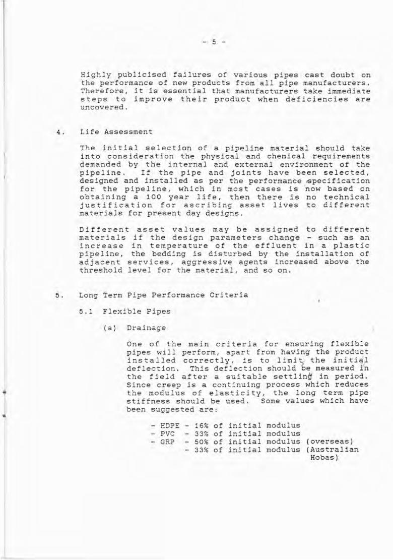
High~y publicised failures of various pipes cast doubt onthe performance of new products from all pipe manufacturers.Therefore, it is essential that manufacturers take immediatesteps to improve their product when deficiencies areuncovered.
4. Life Assessment
The initial selection of a pipeline material should takeinto consideration the physical and chemical requirementsdemanded by the internal and external environment of thepipeline. If the pipe and joints have been selected,designed and installed as per the performance pecificationfor the pipeline, which in most cases is ~ow based onobtaining a 100 year life, then there is no technicaljustification for ascribing asset lives to differentmaterials for present day designs.
asset values may be assigned to differentif the design parameters change - such as anin temperature of the effluent in a plasticthe bedding is disturbed by the installation of
services! aggressive agents increased above thelevel for the material! and so on.
Differentmaterialsincreasepipeline,adjacentthreshold
5. Long Term Pipe Performance Criteria
5.1 Flexible Pipes
(a) Drainage
One of the main criteria for ensuring flexiblepipes will perform, apart from having the productins tall e d cor r e c t 1y , i s t 0 1 i mi t,_ t he i nit i a1deflection. This deflection should be measured inthe field after a suitable settlin~ in period.Since creep is a continuing process which reducesthe modulus of elasticity! the long term pipestiffness should be used. Some values which havebeen suggested are:
- HD?E - 16% of initial modulus- PVC - 33% of initial modulus- GRP - 50% of initial modulus (overseas)
- 33% of initial modulus (AustralianHobas)

II
- 6 -
Allowances need to be made for the temperature andthe correct pipe stiffness chosen to suit the soilconditions. Table 1.
(b) Pressure
In the case of pressure pipe, there is a long termloss in strain under constant load. In the caseof uPVC each material must have a one hour minimumstrength of 39.6 MPa and a long term 50 yearstrength of 23.6 MPa as per AS 1477, UnplasticizedPVC (uPVC) Pipes and Fittings for PressureApplications. The attached Graph 1 shows a safetyfactor of 2.6 for a class 12 pipe (100 m head) a~d
a factor of safety of 4.2 for the blue brute at a100 m Melbourne Board of Worl(s working stress.The 100 diameter pipe has been approved by theMMBW and it has been used for almost 10 years.
The higher factor of safety by the MMBW is inagreement with some investigators which suggest amaximum working stress of 6 MPa because of theaffect of cyclic pressure variations and thereduction in strength due to scratches and nicksin the material.
A similar procedure is suggested for calcu.latingthe limiting strain for glass reinforced products.The Draft Standard DR 87071 Plastics-Glass-FibreReinforced Plastics (GRP) Methods of Test suggestshow to de~ermine the long term (50 year) pressureresistance and the hydrostatic regression ratio ofglass-fibre reinforced plastic pipe. In addition,in the Draft Australian Standard - Glass-FibreReinforced Thermosetting Plastics - PolyesterBased Water Supply, Sewage and DrainageApplications it is proposed that on the 50 yearlong term strength, a factor of safety of 1.8should be used for high pressure pipes reducing to2.1 on the lowest pressure.

- 7 -
The Draft Standard is in agreement with the paperby Schlehofer and Carlstrom (Ref. 1) whichprovides test data on external pressure and cyclicloads on GRP pipe. In the conclusions they state"The long-term tests described are directlyoriented towards practical conditions: and"Knowledge of these long term values is of greaterimportance for the calculation and design of allorganic materials as a result of the effect thatthese materials have no real long-term strength asusual with metallic materials (e.g. Wohler-line).
5.2 Rigid Pipe
(a) Vitrified Clay Pipe,,
Rigid load bearing pipes have been used withvarious factors of safety depending on the type ofmaterial. No long term stress reduction orrelaxation is taken into account for thetraditional materials such as concrete or vitrifiedclay primarily because these products weredeveloped prior to this method of examination.
Vitrified clay pipe has a similar ultimate loadrequirement as that for concrete pipe. Namely - afactor of safety of 1.5 on the design load. Thesepipes are to conform to AS 1741 Vitrified ClayPipes and they are also required to pass a two orthree edge bearing test load (ultimate load only).
(b) Cellulose Fibre Reinforced Pipe
The new cellulose fibre reinforced pipe is notcovered by an Australian or Overseas Standard. Thetechnical information which is available is frpmthe Australian manufacturer and othe~ Associations.
'"He f (1) Long Term Testing of Centrifugally Cast Glass
Fibre Reinforced Plastic Pipes - Advances inUnderground Pipeline Engineering - Edited by Jey KJeyapalan, Published by the American Society ofEngineers.

I
I
- 8 -
T~is product consists of a mortar containingapproximately 46% cement, 46% silica anc 8%cellulose by mass. The volume of organic materialis substantial and warrants long term sustainedload testing similar to that conducted on the glassreinforced plastic pipe. The CPAA have provided aTechnical Bulletin 01/87 and 02/87 covering the"Sustained Load Testing of Pipes" for yourinformation.
The Bulletin provides background information on howthe tests are to be condacted and provides a methodby which the results can be interpreted. T~e testis very simple. The dry strength of the product isdetermined by the two or three edge beari~g method.Then samples of the p~oduct are placed in water anda constant load applied to the product again in theform of the two or three ec.ge bear ing test. Thet:ne to failure of t~e product is recorced. Loadsare chosen so that failures will ocur up to 10 000hours. These failure points are used to calculatethe regression line, using the least mean sqaaremethod of analysis. The extrapolated st~ength of aproduct can be calculated for 100 years service.
In the case of the cellulose fibre reinforced pipethe retained strength ratio is 0.26 to 0.32. Iffor example a strength equivalent to that for otherload bearing pipes is required (F. S of 1. 5 forconcrete) then the minimum ultimate test loadshould be 1.0/(0.26 to 0.32) x 1.5 or 4.7 to 5.8tir:les the design load. The design practice anumber of months ago was to prov:'de a pipe whichhas a strength 3.0 times the design load. This isconfirmed by a specification put o~t by theDepartment of Main Roads in NSW in which they statethe creep strength at 50 years is expected to beequal to the initial design load.
The question arises, doesoccur wi th other materialsIf so, should a higherconsidered.
the same strength losssuch as concrete pipe.factor of safety be

( c)
- 9 -
Concrete Pipe
Concrete pipe is desigDed to meet two requirements- a minimum cracking load and an ultimate load.The minimum cracking load is in effect the maximumworking load for t:"e product. The ultimatestrength of the product is required by AS 1342 tobe 1.5 times greater than the cracking load. Thesetest load requirements are usually imposed on theconcrete pipe 7 to 14 days after manufacture. Atthis period in time, the concrete strength and thebond strength to the reinforcement has onlyachieved 70 to 80 percent of its potential. Thistesting procedure provides an additional factor ofsafety to the customer because the' product willcontinue to gain in strength in time.
The effect that these two factors will have on theconcrete pipe will be to increase the long termstrength of the product. Tests on concrete pipeafter 30 or more years of service in fact confirmthis strength increase.
All this proves is that pipes made 30 to 50 yearsago still have a satisfQctory performance. It doesnot prove that current production usingcementatious materials manufactured from modernplants will perform in a similar manner.
To ensure current materials and manufacturingtechniques are as good or better than they were 30or eveD 50 years ago, sustained load tests havebeen started on 600 mm diameter X Class, steelreinforced concrete pipes by Humes and independanttests started at AMDEL in South Australia. As oftoday test samples under 90% of t~e actual drystrength of the pipe, which happens to be 104% ofthe specified ultimate stre:1gth in ks 1342 havesustained this load for 139 days. At AMDEL, testsat 8596 of the ultimate dry strength on the sametype of pipe, but from a different factory hasreached 60 days wi thout incident. The testconditions were identical to that for the cellulosepipe. A copy of the Humes report is available.

- 10 -
Based on a minimum 20% to 30% gain in strength intime, I would now not expect the product to fai Ibecause of creep in the materials. We can now beconfident that the products that are supplied todayare as good or better than the products supplied 50years ago.
6. Abrasion Resistance
Another important physical property of a material is itsabrasion resistance. The abrasion resistance of a productmust suit the environment to which it will be SUbjected.
Abrasion resistance for a drainage pipe is becoming more of aconcern to specif:'ers because of t!1e expansion of housingestates into hil:y terrain. This type of subdivisionrequires more engineering expertise to cope with the steepergrades and potentially higher velocities of the water in thedrains.
The change to providing building si tes completely servicedprior to construct:on has had an influence on the amount ofabrasion which nOvl occurs in pipelines. It is during theconstruction period on the site that the large quantities ofdebris in the form of aggregate, soil and even bric~-{s findtheir way into the drainage system. These constituents willin time, abrade t~e invert of the pipeline. The extent ofthe abrasion will depend on the veloci ty of the water, thequantity and type of debris and the type of material used inthe manufacture of the pipe.
Some test data is available on the relative abrasionresistance of concrete, asbestos ceme;'lt, vitrified c:"ay,glass reinforced plastic, PVC and high density polyethyleneplastic from an investigation carried out at the DarmstadtTechnical University in West Germany over fifteen years ago.This information is provided in Graph 2.
Recently the Concrete Pipe Association of Australiacommissioned the Australian Mineral Development andEngineering Laboratories (AMDEL) to carry out abrasion trialson reinforced concrete pipe, asbestos cement pipe andcellulose cement pipe to determine the relative performanceof products made with Australian materials. The resu.ltsappear to be in very close agreement to the Darmstadtresul ts. The loss in wall thickness after 1 400 000 cyclesfor reinforced concrete pipe, asbestos cement pipe andcellulose cement pipe was 2, 7, 19 mm respectively.

- 12 -
In hindsight, I now believe the wear rates for the asbestosand cellulose pipe are low because of the long period betweenc!1?nging the surcharge. The abrasive charge is usuallychanged on the completion of 100 000 cycles, however, at10 000 to 20 000 cycles, the abraded fibre material is ofsufficient volume to act as a buffer. Wear is reduced. Thisis not the case with other materials such as PVC, HDPE,concrete, GRP and vitrified clay.
It is much easier for the designe~ to sit down with a set offormulae to calculate the load strength of a pipe than toassess the abrasion resistance required for the pipeline. Ifthe designer expects some abrasion in the line, a goodabrasion resistant material should be used and tMe roughnesscoe f f icien t for the mater ial increased. The Concrete PipeAssociation of Australia adopts a conservative approach inthis area. In its Technical Manual, Hydraulics of PrecastConcrete Conduits, Section 4.2.1 the recommendation is to usea Colebrook White K value of 0.15 and state "having regard tothe effect of the deb~is a value 0: 0.6 seems reasonable, butit must be realized that no tests under these conditions areknown to exist".
This conservative approach should be taken formaterials, especially those which have a lowerresistance than concrete.
7. Durability
all pipeabrasion
In addition to determining the physical requirements of theproduct, the durabi I i ty of the rna te~ ial must be assessed toensure compatibility with the environment.
There is a large amount of information available on thetheoretical resistance of materials to chemi~al attack.Short term tests have been developed to simulate... long termexposure conditions, however, the only unchallengabletechnical information is proven long term field performance.
Recently, the Concrete Pipe Association of Australia hasinvestigated the long term performance of concrete pipe andpublished information on the limits on aggressive agents inthe soil. The internal and external exposure conditions forthe pipe has been assessed. This information is attached asTable 2.

- 12 -
This Table covers the allowable limits for acid, carbondioxide, sulphate, chlorides and magnesium in relation tovarious soil and terrain conditions. These limits are basedon low water cement ratio concrete found in pipes made by theroller suspension or the centrifugally spun processes.
It should be noted that these aggressive conditions do notoccur very often. They are the exception rather than therule. However, exceptions do occur and where the aggressivelimits are exceeded there are protection methods available toprevent the aggressive ions from reacting or penetrating theconcrete. These methods range from a simple increase inconcrete cover to provide a sacrificial layer, to the use ofcoatings to prevent the aggressive ions reac~ing thereinforcement. The aggressive condi tion which occurs mostoften is the placement of steel reinforced concrete in amarine environment. When this environment is encountered,the manufacturer should be consulted.
It is suggested that when soil tests indicate aggressivecondi tions exist, the manufacturer's recommendations shouldbe obtained for their product.
The steel reinforced concrete pipe is not the only productwhich requires protection if placed in an aggressiveenvironment. The manufacturers of other pipe products canalso supply tables containing allowable limits to ensure thatthe i r protducts will perform when subjected to chenmicals,heat and high strains.
8. Flammability of Pipe Materials
Fires in concrete pipe do not affect the structural strength,flow capacity, corrosion and abrasion resistance.Information is available through the CPAA in the form of apaper entitled "Buried Facts - Fires in sewers and culverts".This brochure, which is an American Concrete Pipe Associationpublication, provides technical information on theperformance of concrete pipe, corrugated steel pipe wi th anasphalt or polymeric coating, corrugated aluminium pipe,ribbed and solid wall PVC pipe, ABS composite and ribbedpolyethylene pipe.
The incidence of fires can be of major concern. This designrequirement should be taken into consideration where flamableliquids are stored near the pipeline or in some cases wherethere is frequent traffic by petroleum loaded tankers.

,,
- 13 -
The flammability of some pipe materials has been highlightedby a fire in a 450 mm diameter high density polyethylene pipein South Austral ia (handouts are available). The cause ofthe fire was put down to vandalism.
9. Freeze Thaw Protection
The water absorption of a cement matrix is related to theability of the product to resist frost action or the cyclicfreezing and thawing of the water in the wall of a pipe. Therate of water absorption is very critical to the freeze thawresistance of a material.
Some typical water absorption values for the products thatwere tested for abrasion resistance at the DarmstadtTechnical University in Germany are:
TABLE 3
TESTED WATERMETHOD ABSORPTION
(a) high density polyethylene ASTM D570* < 0.1
(b) polyvinyl chloride ASTM D570 0.2 to 1.0
( c ) polyester (glass reinforced ASTM D570 0.12 to 2.5plastic)
(d) concrete (spun and roller AS 1342 3.0 to 6.0suspension)
(e) asbestos cement AS 1342 11.0 to 14.0
( f) cellulose cement AS 1342 23.0 to 26.0
* The ASTM water absorption test is not as seve~e as theAS 1342 test.
11/
In the case of concrete, it should be dense, sound,adequately cured and compacted. Graph 3 from the "Propertiesof Concrete by A M Neville p 467 shows the resistance ofconcrete to frost action.
Concrete made by the centrifugally spun and roller suspensionprocesses have water cement ratios below 0.38 and in someinstances below 0.30.
Frost or freeze thaw damage can be averted by burying thepipeline below the ground frost line. In most cases, in coldclimates, a depth of two metres would be necessary.

- 14 -
10. Rubber Rings
The rubber ring is an integral part of the pipeline. Seriousconsideration must also be given to the stability of therubber ring when subjected to the effluent in the pipelineand the surrounding environment.
I do not have sufficient time to deal in depth with thevarious materials which are available. However, this matterneeds to be assessed with the same amount of diligence as thematerials for the pipe.
11. Summary
The preceeding informat~on is not a~ exha~stive treatment onthe requirements for a pipe material, but it gives an ins:~ht
into· some of the factors which should be considered in thedesign. If you have a need for further information on theperformance of pipe materials please contact the ConcretePipe Association or the affiliated companies.
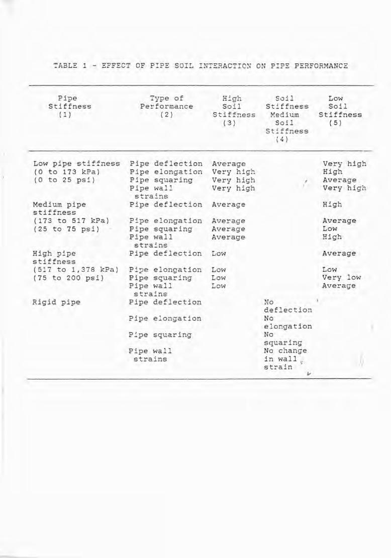
~ABLE 1 - EFFECT OF PIPE SOIL INT~RACTION ON PIPE PERFORMANCE
PipeStiffness
( 1 )
Low pipe stiffness(0 to 173 kPa)(0 to 25 psi)
Medium pipestiffness(173 to 517 kPa)(25 to 75 psi)
High pipestiffness(517 to 1,378 kPa)(75 to 200 psi).
Rigid pipe
Type ofPe!'formance
( 2 )
Pipe deflectionPipe elongationPipe squaringPipe wal_strains
Pipe deflection
Pipe elongationPipe squaringPipe wallstrains
Pipe deflection
Pipe elongationPipe squaringPipe wallstrains
Pipe deflection
Pipe elongation
Pipe squaring
Pipe wallstrains
HighSoil
Stiffness( 3 )
AverageVery highVery highVery high
Average
AverageAverageAverage
Low
LowLowLow
SoilStiffness
MediumSoil
Stiffness(4 )
,,
NodeflectionNoelongationNosquaringNo changein wall.strain \0
LowSoil
Stiffness( 5 )
Very highHighAverageVery high
High
AverageLowHigh
Average
LowVery lowAverage
);/

TPBLE L
AGGRESSIVE CONSTITUENTS - LIMITS FOR U~~ROTE~!ED R.S. OR SPUNCONCRETE PIPES -.Ehtracted from a CPA Paper by D~. J.T. Gourley andDr. N.L. Harrison on liThe Resistance of Buried COncrete Pipe" to COrrosion.
------ NO LIMIT ------
SOIL/TERRAIN CLASSIFICATIO~l'
1. ACID
pH *Exchangeable soil acid(ml of O.l"M NcORconsumed by 100 g ofair dried soil)
2. AGGRESSIVE CO2
(ppm) *"
3. SULPHATEc:
(ppm S04 ) *TYPE A PORTLAND CEMENT
TYPE C OR D
4. CHLORIDE
(Z Cl-) *UNP£INFORCED CONCP£TE
REINFORCED CONCRETE3
5. MAGNESIUM.L.I..
(ppm Mg' .) *
CLAY/STAGNANT
{ 4-.5
t 70
t 150
t 1000
*10000
t 2
NO LIMIT
MEDIUM
{ 5.0
t 50
t 50
* 1000
*10000
*2
NO LIMIT
SANDY/FLOWING
t 5.5
t 30
t 15
t 1000
tl0000
* 2
* 2000
2* in ground water or soil extract
NOTES:
1. Soil/Terrain Classification
Clay/Stagnant:
Sandy/Flowing:
Medium:
2. Soil Extract:
Heavy soil such as clay with little or noground water movement.
Permeable soil combined with a significantflow rate of ground ~ater.
Inte~ediate betvee~ the above.
2:1 ~ater to soil by weight.
3. Continuously submerged in sea or ground water. Tidal or fluctuatingsaline ground water conditions must be treated as separate individualcases, often requiring additional protective measures.
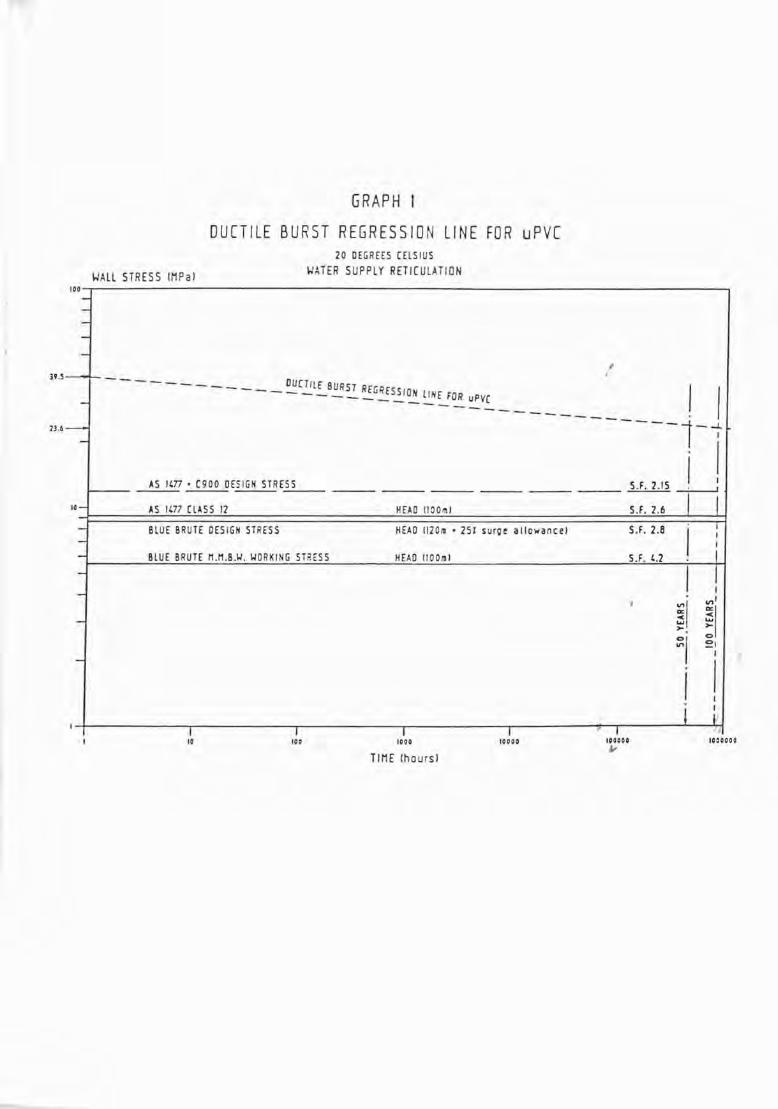
GRAPH I
DUCTILE BURST REGRESSION LINE FOR uPVC
WALL STRESS IMPa)
20 DEGREES [ElSIUS
WATER SUPPLY RETICULATION
100-,-----------------------------------------,-----
1000000
S.F. 2.8 I :S.F. U I
,,
HEAD 1I00ml
HEAD 1I201ll • 251 surge allowancel
HEAD 11001111
I !
~I ~i~I ~:
I !i ~I-I--------r-,------I.-----------".-----------rl--------:-'-,I----..t...--'r,f,
10 100 1000 10000 100000j,
H.S-f- - - - DUCT- - - - - - - - __ IlE BURST REGRESSION L I I
_ ---- ~~DR UPV[---------------1--7
. II IS.F. 2.15 I I'
5.F. 2.6
23.6- -
AS 1m· [900 DESIGN STRESS
10- AS 1m CLASS 12
- BLUE BRUTE DESIGN STRESS-- BLUE BRUTE M.M.B.\.I. WORKING STilESS
--
-
-
TIME (hoursl

GRAPH 2
COMPARISON OF DIFFERENT PIPE ~I1ATERIALS
ABRASION RESISTANCE
600000400000
S ESTOS CEMENT PIPE
200000o
1.0
3.0
z0
2.5- GRP(f)
<0:en<:lL. 2.00-.J-t-O-w 1.50
LOAD CYCLES N

GRAPH 3
4000r---.----.-----,------.----.--.
JI
,,
I
Non-Air-Entrcined_.....,. -...,..-..--~
<lJU'l:J~0.c 3000~'r----t----+-----i------+------1Urno CJ~3
U'l c<lJ .-u U') 2 000r-t---r-----+----~---+----J---~>JU'lUo__ -1
o 0--L 0
~~ 1000r--T---t---==:::.....c:--+-----+----+---~E:J
Z
oL-_-L:::::::::1=====±::=~=±:===~0·35 0'L,5 0·55 0·65 0·B5
\voter/Cement Ratio


Competitive Elements in theAustralian Pipe Scene!
by
Dr. Michael A. Peck
J~ I

Dr. Michael Arthur Peck
Qualifications• B.Sc. (Eng.) in Chemical Engineering from London University.• Ph.D. from University of New South Wales (completed in 1970).
In 1973 he joined Humes Limited, and the concrete industry, working inprecast concrete pipe production in both Regional and Head Officemanagement positions for 7 years, moving on to the position of ManagerConcrete R&D (4 years), until taking up his current position - MarketingManager Concrete - which includes a continuing responsibililty for product/market/strategic research and development.
Michael is a past Chairman of the CPAA Marketing Committee.

What has caused the change?
CPAA24
CPAA - NATIOOAL SEMINAR 1987
Carpetitive Elements in the Australian Pipe Scene
by
Dr. Michael A. Peck
snlPSIS
The structure of the presentation is as follows:
a general introduction to describe the background to the current highlycompetitive market place.
an overview of the dynamics of the Australian pipe market, the key players,basic market statistics, the competitive materials on offer.
threats and opportunities.
marketing strategies of same of the key players - illustrated through theirpromotional material.
Because of the sensitive nature of some of the material shown during thepresentation only that sourced fran the CPM is attached to these notes.
For my purpose "pipe" is taken to be pipes lOOnrn and greater in diameter - we arenot talking about tubing, small diameter conduits, e.g. soil, waste, ventplastic is excluded, etc.
Your first perception of the pipe market is probably of a relatively stable andorderly situation: but a highly structured market where each of the companiesand each pipe material maintains a somewhat stable market share.
Up until about 2 - 3 years ago that was indeed the position. However, since thenit has become increasingly hostile and today is essentially outright warfare. ;
p
The central and essential reason was the decision by James Hardie IndustriesLtmited to phase out ASBESTOS pipe - JH discontinued their asbestos pipemanufacture on 31 March 1987, although they remain in the supply of asbestosproducts for a limited time.
One should not accept that the cessation of manufacture of asbestos products inAustralia will mean a decline in the interest of pressure groups, or thoseaffected by asbestos related diseases.
Asbestos is an issue that will be around for a long time.

Page 2
This decision by Hardies created the situation of a substantial market, acrossmany market segments, which may be considered as "up for grabs". I say this forthree reasons:
1. JHI cannot replace asbestos by a single substitute product - they haveadopted a portfolio approach.
2. The JHI portfolio has led to their penetration into areas considered byothers to be "their" market. The plant investment has led to an increasein pipe industry capacity at a time of slackening demand.
3. Other players see a unique opportuni ty to increase market share byoccupation of old asbestos markets.
Essentially - we are involved in a material substitution battle.
DYNAMICS OF THE PIPE MARKET
A series of overheads will be shown to cover the following points:
Major Players
Market Statistics -
Materials Offered -
Individual CompaniesIndustry Associations
Total Market by End UseTotal Market by MaterialConcrete National Pipe Market and End UseNational Stormwater Market
Storrnwater Products Offered in Market
These products are examined using "degrees of threat" to the concrete industry,as follCMs:
*** a substantial threat to the industry - requires definite action** moderate threat - requires defensive measures* no real threat
In the storrnwater market the two largest threats to concrete are cellulose FRCand Ribloc pipes.
The other materials in the JHI portfolio are more threatening in other markets,Le.
Sewer - BaukuWater Stg>ly - lbbas
TBRFATS AND OPPORTUNITIES
The composite threat posed by the JHI product portfolio will be examined in termsof
End UseDiameterCapacity

Page 3.
Key points to be made are:
1. Asbestos is a remarkable, unique material with characteristics not able tobe reproduced by any currently known substitute fibre - and it's cheap.
2. Capacity - all asbestos plant can be converted to make cellulose pipe.Effectively, a capacity expansion in the stormwater market.
3. The introduction of Hobas and Bauku has led to an expansion of effectivecapacity in the sewer market segment.
4. Product range has led to the enlargement of diameter competition.
JHI have substantial disadvantages with their new product portfolio.
The obvious one is product "ETl'NESS FCR PURPalE", Le. will the product do whatis claimed in the longer term? That is performance over time where we mustconsider the period of acceptable life to be 100 years.
Product acceptance notwithstanding there are a number of strategic problems thatarise in moving from a single product to a multi-product portfolio.
If one examines the various products one finds a distinctive lack of synergybetween them - exacerbated by the JHI Divisional organisation, and the adoptionof individual rather than collective product strategies.
The concrete industry has not had to SELL steel reinforced concrete p~pe for thelast 50 years or so. However, the realisation of the competitive forces in themarket place in the last two years has resulted in the industry, through itsAssociation, having to learn about MARKETING itself and its product - SteelReinforced Concrete Pipe.
The Association has followed a strategic programme aimed at education of the enduser - not only in the benefits of using concrete pipe but also in providinginformation about competitors' products: information that is not, being made I
available by the various manufacturers but 'N'hich is, we would su'aniJ:, desired byspecifying and design engineers and by Authorities themselves.
All sorts of claims are being made by JH about the performance of theirreplacement materials.
It is the policy of our Association to inform its custaners and potentialcustomers, on the technical characteristics of all pipe products - but to do sowith integrity. This has been achieved by substantiation of its own informationthrough the use of an external, independent and reputable scientificorganisation. In our case AMDEL.
Our modus operandi is:
"If it is not right, don't do it; if it is not true, don't say it.·
Marcus Aurelius<121-180)

Page 4.
The objectives of the Association in its marketing programme include:
1. Protection of its own standards and specifications from attack and frommisapplication by other materials.
2. Research into competitive pipe materials.
3. Submission of technical argument to Authorities, specifiers and designengineers.
4. Both defensive and offensive promotion - with the effort involvingadvertising, seminars, in-house training, case history data and publicrelations activities.
Let us look in some detail at the advertising that has taken place - to see itsdevelopment, to see how the issues have changed, and to illustrate some elementsof the strategies of the various players.
Taking events chronologically we have
Cellulose FRC - ad is evidence of JHI desire to join the "concrete community"but with a superior product. Ad replaced by publicity of "NewProduct" type.
CPM - the above was answered by two advertisements with the copyemphasizing durability and coverage by Australian Standards.
The CPM response was reactive and defensive in nature - we are a passiveindustry! What was needed was an offensive strategy - to ~ert the leadershiprole ourselves.
We had to understand what purchasers of pipe really wanted from a product. Inshort they seek permanence - DURABILITY - in terms of
*
*
load carrying capacity
hydraulic capacity
resistance to attack (chemical)
abrasion resistance
In depth in-house evaluations of * have taken place and both evidencedsignificant technical weaknesses ln cellulose FRC.
We further had to appreciate the key strength, and any weakness in that strength,of JHI. The Association determined:
strength - technical credibility
weakness - supporting/promoting a sub-standard product compared withasbestos and steel reinforced concrete

Page 5.
and decided on a strategy to concentrate on
firstly, abrasion resistance - results quicker to achieve and able to bepresented powerfully
secondly, load carrying capacity - a harder message to get across but ofmore fundamental importance.
One should not forget that both these features will occur simultaneously.The result is ......•..•. !!!
Abrasion Resistance
The Association had early research results from Monier-Rocla and Amdel. Thesewere used to develop a 1/2 page ad, targetted at the readership of EngineersAustralia, with a creative use of media. ,
r
The opening of the campaign was folla.ved by what we termed the "Buck Rogers" ad,which linked abrasion resistance to durability, ffi3.intained the exposure of theabraded pipe cross-sections, was educational, mentioned the carmunityresponsibility of engineers, and was positive of our a-m product.
In other words we were moving ta.vards adopting a leadership role ourselves:positioning our product and cellulose with increased authority.
JHI has not answered the CPAA ads openly. Let's say there has been an exchangeof correspondence and that they have stepped up their social and psychologicalmarketing directly with end users. There is little doubt, in our opinion, thatJHI has developed over the years, and ffi3.intains, a significant advantage in thespecial treatment by, and access to, Government instrumentalities. Thisadvantage is especially useful to them nON.
(There have been two developments of significance in the abrasion debate since thead campaign finished:
1. Release of the CPAA docurrent "Abrasion Resistance of Concrete Pipes".
2. The results from a longitudinal abrasion test conducted by Humes Concrete.t" I
Both advance the debate and help to correct the misinformation in the marketplace). ",
JHI Institutional Ad - Fibre Cement Division
In April 1987 it was interesting to see .JHI attempting to regain a leadershipposition. They have linked together cellulose PRC and Hobas for the first time.There are a number of claims which the Association would dispute - the mostoutrageous one being that Hobas is somehON an Australian technology, rather thana successful European development licensed to JHI.
Durability
The current CPAA campaign will have come to your attention, Perhaps with someimpact. This achievement of "impact" was a significant part of the creativebrief.

Page 6.
The issue being addressed is the sustained load perforrrance of cellulose mcccrnpared with steel reinforced concrete pipe. As you have already heard, theresults we have access to - both in-house and independent - suggest that you needto specify a test load 4.5 times that of an equivalent concrete pipe I S proofload, to have some assurance of long term performance. Another way of lookingat the issue (since JHI tacitly acknowledge a factor of 3 - but no allowance fora safety margin) is that if you specify, say a 600mrn Class X concrete pipe, youwould need to specify at least Class Y cellulose FRC pipe, if not Class Z.
The present campaign will run for a number of weeks. It is supported bypublicity and an extensive data base - the preparation of a number of CPAA andHumes Technical Bulletins being a feature. The evidence of the educationalcomponent of our programme is before you - this is just one of many seminarsbeing held around the country to inform Engineers of the Association's strongcpinions.
The intrcduction of a "new" material places a special responsibility on themanufacturer involved. OUr approach to sustained load testing and the use ofthe data to derive short term test levels was develoPed by Humes for its Resinagpipe intrcduction. Thus, we are not asking others to recognise principles wedid not apply to ourselves.
It is of interest that the development of cellulose pipe seems to be continuingthere has been a number of changes noted in the prcduct literature, e.g. wallthickness increases, joint profile additions, internal diameter changes, etc.There is also a degree of misleading information, e.g. pertaining to pipehydraulics.
Bauku
Enough of PRC - let's take a quick look at Bauku advertising.
This prcduct is manufactured by Hardie Iplex and different strategic positioningis evident.
Iplex has used the approach of "implied" endorsement by Authorities ofunquestioned reputation.
The Bauku advertising history is as follows:
Sydney Water Board - ad withdrawn after substantial problems withBungaribee sewer became evident.
Port of Melbourne Authority - we are aware the PMA has a policy of noprcduct endorsement. Ad withdrawn after a matter of weeks.
This form of strategy has problems:
if prcduct does not perform
if Authority objects to use of its name
leaves opening for canpetitors with longer history to strike back verymeaningfully (the latest Clay Pipe Manufacturer Association ad isa classic example).

Page 7.
Since the above problems Iplex apPear to have dropped the association withAuthorities. In their place they have used
product ad - same photograph as PMA ad
Corporate ad featuring Bauku as only one of a number of products:rredia similar to previous CPAA use.
use of
Again claims are misleading - for instance we would reject the nature of thereference to "Australian Standard".
The use of Authority names seems to hold an attraction within JHI. The latestFRC leaflet has been over-printed with "Approved by the DMR (MR Form 861)" andmakes another reference inside to the DMR. We understand the DMR has takenaction to have such literature withdrawn.
Sunmary,,
I have shawn by illustration some examples of the advertising, and related thisto the fundamental marketing strategies of the key players. Most of the battleis fought out in Engineers Australia and you may care to follow it by keepingcopies of the ads as they apPear and examining them for details of the strategicroves being made.
We know steel reinforced concrete pipe best - as, in fact, do you. It isreliable and proven by an unchallenged record of Performance over many, manyyears. We want to continue to supply quality information on SRCP and othermaterials to protect ourselves, the engineering profession and the community at~r~. '
The CPAA has published and has available technical literature to support the useof SRCP and it is freely available to you. If we can help with any otherinformation then simply request it of us.
I have attempted in my presentation to counter any suggestion that the Australianpipe industry is dull and boring. It really is a hot-bed of ingigue andpolitical and marketing manoeuvres. My objective will have been achieved if youare able now to appreciate m::>re broadly what is at stake, how the ompetitorsrate in their product offerings, and how strategic marketing is being used toinfluence you in the placement of your next pipe order.
* * * * * * *
Theargumentsinfavourof
steel-reinforced•concretepipesare
verystrongindeed.Right now, steel reinforced concrete pipe i being challenged in the market by a type of pipe
that claims to break new ground in reinforcement technology.
As a sub titute for steel, it features cellulose fibre that seems to offer comparable strength
on paper, but in the ground, who knows?
Only time will tell. And in the meantime, you take the ri k.When specifying concrete pipe, keep in mind that steel reinforced concrete pipe is subjected
to the severe tests laid down by the long established and accepted Australian Standards.
Not only that, but all individual raw materials used in manufacture, including the steel
reinforcement, are also covered by Australian Standards.
And as for the test of time, thousands of kilometres of steel reinforced concrete pipe laid
in the 1920s are still working like they were laid yesterday.
So if anybody tries to sell you anything les , offer them a few concrete arguments in favour
of steel rei nforcement.
For more information on the strengths of steel rei nforced concrete pipe, contact the Concrete
Pipe Association of Australia, 276 Glen Eira Road El ternwick, Vic. 3185. Phone (03) 528 2107.
•-.• • Concrete PipeAssociation ofAustralia
CPA 1887A

When _au bury a pipe, and you don't demand the strength of steel reinforcement,you might find yourself burying a mistake.
I
Because a concrete pipe has got to last underground for a lifetime. So you won't,yant to experiment with ideas in reinforcement when theyre unproven in the one testthat reall matters.
The test over time.So no matter how cellulose fibre looks on paper, it makes alot more sense to specify a pipe with a proven track record under the groupd. And that's I
a steel rei nforced concrete pipe. "ot only is it tough (it has to be to meet the Australian Standards of manufacture),
it actually gets stronger with age. And unlike most other pipes on the market, it has along, long history of proven success.
So, in many respect choosing the right pipe isn't such a tough decision after all.);<or more information on the benefits of steel reinforced concrete pipe, contact the
Concrete Pipe Association of Australia, 276 Glen Eira Road, Elstern",ick, Vic. 3IHS.Phone: (03) 528 2107.
• Concrete PipeAssociation ofAustraliaCPA 18878

276 Glen Elra Road.Eislernwick, VictOria 3185Telephone (03) 528 2107
APOLOGYDue to the overwhelming response to previousadvertisements highlighting the abrasion resistanceof steel reinforced concrete over cellulose pipe, andsubsequent strength loss ratio, the Association wishesto apologise for any delay you may have experiencedin receiving your copy of the AM DEL Reportsubstantiating those weaknesses.
Additional copies are currently being printed andwi II be despatched posthaste.
CONCRETE PI PEASSOCIATIONOF AUSTRALIA ~§~
Circl. 5 on r••de, service coupon on page 62
/8 Engineers Australia November 28 /986

, ~~~~~~--'
. ,vo~~ ~Q~~
REDUCE -----~~~•.Rif,f ~
STORM WAr;C4T4slRo -.-: ()~ '{()'Uv. NEXTPIA PHIC ABRAS\ON
PIPE GETs 'E PRoJEcr. ONLYSTm R£llIfOR(E\) CONCRErfA~ STRoNGEk WITH AGE. 11IOEPEl\OENl LABOR-
DRY TBTS SHOW STEEL REINfORCED CONCRETE PIPE "TO BE SUPERIOR TO CElLULOSE (FRC) PIPE FOR ABRASIONRESISTANCE BY AFAGOR OF OVER NINE TIMES~THE CONSEQUENT STRENGTH LOSS RATIO FOR CELLULOSE (FRC)PIPE IS CONSIDERABLY HIGHER. STEEl REINFORCEDCONCRETE PIPE PROVIDES APROVEN TOUGHNESS ANDRELIABILITY ON WHICH YOU CAN CONFIDENTLY PRO-TEa YOUR REPUTATION AND COMMUNITY INVESTMENT.Compara lVe pro les after less than 6weeks abrasIon.••
----._--~~- ---
THINK AHEAD. PIPE ABRASION ~ ~COULD COST TOO MUCH.For comparalive data phone (03) 5282107 orfill In, dip and post the coupon
To the Concrete Pipe AssOCIalion of Please send me comparatIVe data onAustraha, 276 Glen Eira Road, ElstemwlCk, steel reinforced concrete pipeVIC 3185 over cellulose
ame
Address
Co and Address
Phone No.
•
CONCRETE PIPE cPAA104
• • ASSOCIATION• • OF AUSTRALIA Inc In "The Australian Mineral Development
SW Laboratones (AMDEL) Report M7293/86

For abrasion data fill in, clip and post the coupon.To the Concrete Pipe Association of Australia (inc. in NSW)276 Glen Eira Road, Elsternwick, Victoria. 3185. Phone: (03) 528 2107
Please send me your abrasion resistance information kit on steel reinforcedconcrete compared with other pipeline materials.
HOW lONG WillSTEEL REINFORCEDCONCRETE PIPElAST?
Australian concrete pipes laid 70 years ago are still in service. Concreteimproves with age.
Not all pipe materials however, have the performance and provendurability of steel reinforced concrete pipe.
THINK AHEAD. PIPE ABRASION COULD COSTTOO MUCH.
•
CONCRETE PIPE• • ASSOCIATION• • OF AUSTRALIA ~~~
?(;i:~~
NEXTQUESTION?
Name:
Address:
Co. &Address:
Phone CPM102

KEY PLAYERS
JAMES HARDIEHUMESMONIERTUBEMAKERSVINIDEX
P.I.A.C,P,A.A.
C.P.M.A.
,,
I/}

AUSTRALIAN PIPE MARKET
SEGMENTATION - BY MATERIAL (CPAA ESTIMATE)
CONCRETE
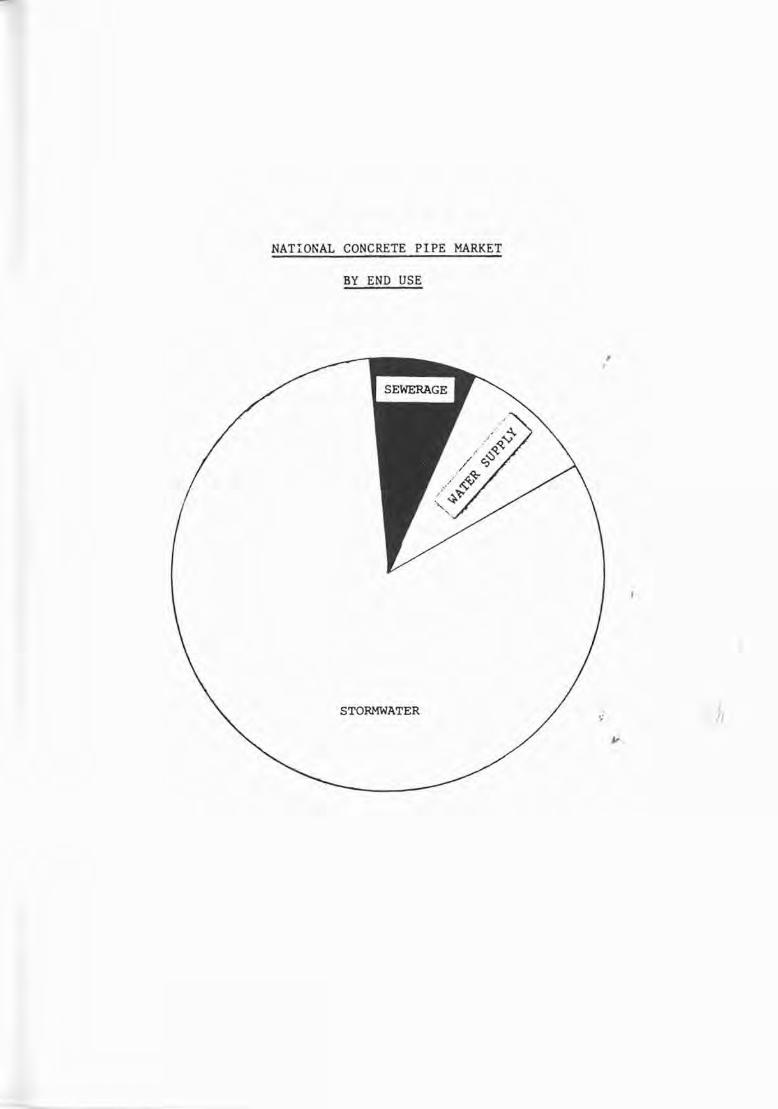
NATIONAL CONCRETE PIPE MARKET
BY END USE
STORMWATER III

COMPETITIVE PRODUCTS AGAINST CONCRETE(NON-TRADITIONAL PRODUCTS)
DEGREE OF THREAT IN MARKET SEGMENTOPPOSITION OFFER
STORMWATER SEWERAGE WATER SUPPLY
I, FRC (CELLULOSE) *** *(*) *(*)
100-750 MM
2, CORRUGATED ** * *
METAL PIPE300-5000 MM
3. UPvc * ** ***
100-375 MM
4, RIBLOC ** * *
100-1200 MM
5, BAUKU (HOPE) *(*) *** *(*)
300-3000 MM
6, HOBAS (GRP) * * *
450-1200 MM
7.

JAMES HARDIE - NEW PRODUCT PORTFOLIO
ASBESTOS100
S/W SEWER W,S,
CELLULOSE100
S/W
750
750
HOBAS
,
I<; II
300
450 1200"' 1
SEWER W, S,
BLACK BRUTE3000
S/W SEWER W,S,