3000 series precision multi function reference calibrator ... · pdf filetransmille ltd....
TRANSCRIPT

TRANSMILLE LTD. Version 3 : Jun 2014 Page 1
3000A Series
Precision Multi Product Calibrator
Calibration Manual

3000A SERIES CALIBRATION MANUAL
TRANSMILLE LTD. Version 3 : Jun 2014 Page 2
TABLE OF CONTENTS
PREPARING FOR CALIBRATION ................................................................................................................ 3
INTRODUCTION .................................................................................................................................................. 3 EQUIPMENT REQUIRED ...................................................................................................................................... 3 OPTIONAL EQUIPMENT ...................................................................................................................................... 3 EQUIPMENT REQUIRED FOR OSCILLOSCOPE (SCPXXX) OPTION CALIBRATION ................................................. 4 EQUIPMENT REQUIRED FOR POWER (PWR50, PWRSINE, PWRDDS) OPTION CALIBRATION ........................... 5
CALIBRATION PASSWORD ........................................................................................................................... 6
CHANGING THE CALIBRATION PASSWORD ........................................................................................................ 6 SET NEW PASSWORD ......................................................................................................................................... 8
MANUAL CALIBRATION .............................................................................................................................. 10
ENTERING CALIBRATION MODE ...................................................................................................................... 11 EXITING CALIBRATION MODE ......................................................................................................................... 14
CALIBRATION PARAMETERS .................................................................................................................... 15
CONNECTIONS ............................................................................................................................................... 16
CALIBRATION OF RANGES ........................................................................................................................ 17
D.C. VOLTAGE ................................................................................................................................................ 17 D.C. CURRENT ................................................................................................................................................ 22 A.C. VOLTAGE ................................................................................................................................................ 27 A.C. CURRENT ................................................................................................................................................ 32 2WIRE Ω ......................................................................................................................................................... 37 4WIRE Ω ......................................................................................................................................................... 41 ACTIVE Ω ........................................................................................................................................................ 45 CAPACITANCE ................................................................................................................................................. 49 FREQUENCY OUTPUT ....................................................................................................................................... 53 INDUCTANCE ................................................................................................................................................... 54 PRT ................................................................................................................................................................. 58 OSCILLOSCOPE – AMPLITUDE .......................................................................................................................... 62 OSCILLOSCOPE – BANDWIDTH ......................................................................................................................... 67 AC POWER (CURRENT OUTPUT) ...................................................................................................................... 71 DC POWER (CURRENT OUTPUT) ...................................................................................................................... 76 A/D INPUT ....................................................................................................................................................... 81

3000A SERIES CALIBRATION MANUAL
TRANSMILLE LTD. Version 3 : Jun 2014 Page 3
Preparing For Calibration
Introduction
The recommended calibration period for the 3000A series calibrators is 12 months.
Extended specifications for 6, 12 and 24 month re-calibration periods are available
from the 3000A extended specifications
Calibration can be achieved using one of two methods:
1. Manual calibration via the front panel controls.
2. Automated closed-loop calibration using ProCal calibration software
In both instances the calibrator should be switched on and allowed to warm up for
the required period as stated in the operator’s manual. Calibration should be
performed in a stable environment where the temperature is stable to within +/- 1ºC
during the calibration.
Equipment Required To calibrate the 3000A series calibrators the following equipment is required: 1. High Accuracy precision Multimeter (example Transmille 8081 / Agilent 3458A opt 002 / Fluke 8508A) 2. LCR Bridge (example Agilent 3. DC Voltage Source (example Transmille 3000 series multiproduct calibrator, Fluke 55xx series multiproduct calibrator 4. High Accuracy Frequency Counter / GPS Frequency Reference / Off-Air Frequency Reference Between these four pieces of equipment it is possible to calibrate all basic functions of the 3000 series calibrators. For units fitted with additional options additional equipment is required
Optional Equipment To perform a full calibration of a 3000A series multiproduct calibrator additional
equipment may be required dependent upon the capabilities of the multimeter being
used

3000A SERIES CALIBRATION MANUAL
TRANSMILLE LTD. Version 3 : Jun 2014 Page 4
For multimeters such as the Agilent 3458A with limited maximum current, a selection
of current shunts are required. These current shunts should be suitable for both DC
and AC current up to 10kHz (5kHz for 2A Range, 1kHz for 30A range) Suggested
current shunt values are listed below, along with the current range they will be used
for :
0.1 Ohm – 2.02A to 30A AC/DC
1 Ohm – 202mA to 2A AC/DC
10 Ohm – 20.2mA to 200mA AC/DC
100 Ohm – 2.02mA to 20mA AC/DC
These shunts are also used for multimeters with insufficient current accuracy for low
current calibration.
Equipment required for Oscilloscope (SCPXXX) option calibration
To calibrate the Oscilloscope output function of the 3000A series, the following
equipment is required
1. High Accuracy precision Multimeter
2. Frequency Counter / GPS Frequency Standard / Off-air Frequency Standard
3. 600MHz – 1GHz Oscilloscope (example Agilent Xfinity Series Oscilloscope)

3000A SERIES CALIBRATION MANUAL
TRANSMILLE LTD. Version 3 : Jun 2014 Page 5
Equipment required for Power (PWR50, PWRSINE, PWRDDS) option calibration
To calibrate the Power output function of the 3000A series, the following equipment
is required
1. High Accuracy precision Multimeter
2. Phase Meter / Oscilloscope
3. Distortion Meter / Distortion Analyser (PWRDDS option only)

3000A SERIES CALIBRATION MANUAL
TRANSMILLE LTD. Version 3 : Jun 2014 Page 6
Calibration Password
Changing the Calibration Password To navigate to the ‘Calibration Password’ screen follow the procedure in the section: ‘Manual Calibration’ to step 3 where the following screen appears: 1. Select SETUP using the soft key
2. Use the ‘Digital Control’ or the ‘Arrow Keys’ to highlight ‘Password’ and then press
SELECT soft key 3. Press SELECT soft key
4. Enter the calibration password (default 0324)

3000A SERIES CALIBRATION MANUAL
TRANSMILLE LTD. Version 3 : Jun 2014 Page 7
The following screen is displayed for approximately 2 seconds:
and then reverts to:
The instrument is now ready to be calibrated and the password can be changed.

3000A SERIES CALIBRATION MANUAL
TRANSMILLE LTD. Version 3 : Jun 2014 Page 8
Set New Password To change the password, complete the following procedure: 1. Select SETUP using the soft key
2. Use the ‘Digital Control’ or the ‘Arrow Keys’ to highlight ‘Password’ and then press
SELECT soft key 2. Use the ‘Digital Control’ or the ‘Arrow Keys’ to highlight ‘Set’ and then press
SELECT soft key
3. ‘Enter New Cal Password’ using function control keys, followed by the ENTER key e.g. 3010

3000A SERIES CALIBRATION MANUAL
TRANSMILLE LTD. Version 3 : Jun 2014 Page 9
The following screen is displayed for approximately 2 seconds:
and then reverts to:
The password has now been changed.
3 0 1 0

3000A SERIES CALIBRATION MANUAL
TRANSMILLE LTD. Version 3 : Jun 2014 Page 10
Manual Calibration
Manual Calibration is achieved using the front panel control:
1. Digital control
2. Function control
3. Soft and Arrow keys
4. Range up and Down keys
5. Output On and Standby keys
Digital Control 1. Adjusts calibrator output 2. Selects calibrator ranges 3. Adjusts calibration factors
Function Control 1. Adjusts calibrator output 2. Enter ‘cal factors’
Soft and Arrow keys 1. Select parameter, range, store, undo & exit – (soft) 2. Change parameter and range (arrow)
Range keys 1. Changes calibration reference point on each range
Output On key – switches output on
Standby key – switches output off

3000A SERIES CALIBRATION MANUAL
TRANSMILLE LTD. Version 3 : Jun 2014 Page 11
Entering Calibration Mode
To navigate to the calibration control screen, complete the following procedure:
1. Select NEXT using the soft key
2. Select NEXT using the soft key
3. Select NEXT using the soft key

3000A SERIES CALIBRATION MANUAL
TRANSMILLE LTD. Version 3 : Jun 2014 Page 12
4. Select CALIBRATE using the soft key
5. ‘Enter Cal Password’ using function control keys
(0324 is the default password) followed by
The following screen is displayed for approximately 2 seconds:
and then reverts to:
The instrument is now ready to be calibrated.
0
0 3 2 4

3000A SERIES CALIBRATION MANUAL
TRANSMILLE LTD. Version 3 : Jun 2014 Page 13
Should the password be entered incorrectly the screen will display
for approximately 2 seconds and then reverts to:
Select CALIBRATE using the soft key to navigate back to ‘Enter Cal Password’
screen and re-enter the password.
3000A SERIES CALIBRATION MANUAL
TRANSMILLE LTD. Version 3 : Jun 2014 Page 14
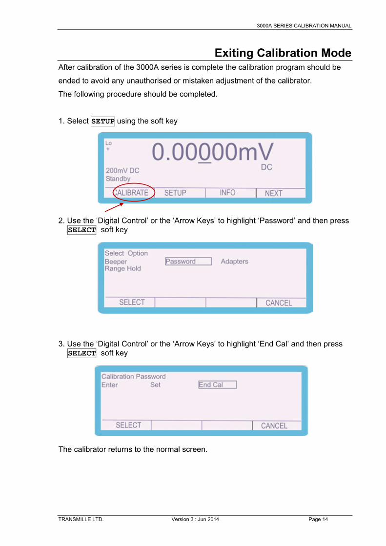
Exiting Calibration Mode After calibration of the 3000A series is complete the calibration program should be
ended to avoid any unauthorised or mistaken adjustment of the calibrator.
The following procedure should be completed.
1. Select SETUP using the soft key
2. Use the ‘Digital Control’ or the ‘Arrow Keys’ to highlight ‘Password’ and then press
SELECT soft key
3. Use the ‘Digital Control’ or the ‘Arrow Keys’ to highlight ‘End Cal’ and then press
SELECT soft key
The calibrator returns to the normal screen.

3000A SERIES CALIBRATION MANUAL
TRANSMILLE LTD. Version 3 : Jun 2014 Page 15
Calibration Parameters With the calibration password entered the different parameters of the instrument can be calibrated: To enter the different parameters, complete the following procedure: 1. Select CALIBRATE using the soft key
2. Use the ‘Digital Control’ or the ‘Arrow Keys’ to highlight the required parameter
e.g. ‘DC Volts’ and then press SELECT soft key
Depending upon the model and options fitted the available functions will vary

3000A SERIES CALIBRATION MANUAL
TRANSMILLE LTD. Version 3 : Jun 2014 Page 16
Connections The output of the 3000A series calibrator should be connected to the precision multimeter as below :
DC & AC Voltage, 2 Wire , Capacitance, Inductance, Active
DC & AC Current up to and including the 2A range
DC & AC Current 20A range - 3050A 30A range - 3041A & 3010A
Oscilloscope Amplitude, Bandwidth, 50kHz Reference
DC & AC Power, 4 Wire PRT
A/D Input Pin 7 – ground Pin 9 - Input
Frequency Output 1Hz – 10MHz frequency output

3000A SERIES CALIBRATION MANUAL
TRANSMILLE LTD. Version 3 : Jun 2014 Page 17
Calibration of Ranges D.C. Voltage
To calibrate the D.C. Voltage parameter, complete the procedure as follows:
1. Select CALIBRATE using the soft key
2. Use the ‘Digital Control’ or the ‘Arrow Keys’ to highlight the required parameter ‘DC Volts’ and then press SELECT soft key
3. Connect the calibrator output voltage terminals to the precision Multimeter.
Ensure that the Multimeter has been zeroed as a system by shorting out the leads and pressing the null button.
4. Use the ‘range up’ and ‘range down’ keys to change the calibration point to ‘Zero Calibration’.

3000A SERIES CALIBRATION MANUAL
TRANSMILLE LTD. Version 3 : Jun 2014 Page 18
5. Press and measure the output ‘Zero Calibration’.
6. To adjust the output, type in the measured value using the keyboard, followed by the ‘ENTER’ key i.e. 0.00028mV
7. The output can also be adjusted by moving the ‘cursor’ to the required digit and adjusting the output using the up / down arrows or the digital control
8. The ‘SHIFT’ key will illuminate to indicate that a change has been made to the calibration of the instrument, however has not yet been stored.
9. To undo the adjustment before storing the changes, press the UNDO soft key. This will remove any changes that have been made to the output of the calibrator.
SHIFT
OUTPUT ON
0 •
0 0 0 2 8 ENTER

3000A SERIES CALIBRATION MANUAL
TRANSMILLE LTD. Version 3 : Jun 2014 Page 19
10. Once the output has been adjusted to within specification, the changes can be stored to long term memory. To store the changes permanently, press the STORE soft key
The following 2 screens are displayed briefly to confirm that the calibration factors have been saved.
After displaying these messages, the shift key will also cease to be illuminated
11. Using the ‘RANGE UP’ and ‘RANGE DOWN’ keys, change the output to
‘Positive Full Scale’
SHIFT
Note: All the calibration points can be adjusted prior to storing the calibration factors (STORE), however if the calibration routine is ended or there is a power failure the new calibration factors will not be saved if STORE has not been pressed.

3000A SERIES CALIBRATION MANUAL
TRANSMILLE LTD. Version 3 : Jun 2014 Page 20
12. Measure the output, and adjust as required using the process described in steps 6 - 10
13. Use the ‘range up’ and ‘range down’ keys to change the calibration point to ‘Negative Full Scale’.
14. Measure the output, and adjust as required using the process described in steps 6 - 10
15. When calibration of this range is complete press the RANGE soft key
16. To continue adjusting other ranges in the DC Voltage function, select ‘DC Volts’ and select the required range

3000A SERIES CALIBRATION MANUAL
TRANSMILLE LTD. Version 3 : Jun 2014 Page 21
17. The ‘2V DC’, ’20V DC’, ‘200V DC’ and ‘1kV DC’ ranges are calibrated in the
same manner. NOTE : The ‘Zero Calibration’ points for both the 200V DC and 1kV DC Ranges
do not occur at 0V. They take place at 5V and 50V respectively.

3000A SERIES CALIBRATION MANUAL
TRANSMILLE LTD. Version 3 : Jun 2014 Page 22
D.C. Current
To calibrate the D.C. Current parameter, complete the procedure as follows:
1. Select CALIBRATE using the soft key
2. Use the ‘Digital Control’ or the ‘Arrow Keys’ to highlight the required parameter ‘DC Amps’ and then press SELECT soft key
3. Use the ‘Digital Control’ or the ‘Arrow Keys’ to highlight the required range e.g. ‘200uA DC’ and then press SELECT soft key
4. Connect the calibrator 2A current terminals to the precision Multimeter. Ensure that the Multimeter has been nulled with the leads disconnected

3000A SERIES CALIBRATION MANUAL
TRANSMILLE LTD. Version 3 : Jun 2014 Page 23
5. Use the ‘range up’ and ‘range down’ keys to change the calibration point to ‘Zero Calibration’ adjustment point
6. Press and measure the output ‘’Zero Calibration’.
7. To adjust the output, type in the measured value using the keyboard, followed by the ‘ENTER’ key i.e. 0.00028uA
8. The output can also be adjusted by moving the ‘cursor’ to the required digit and adjusting the output using the up / down arrows or the digital control
9. The ‘SHIFT’ key will illuminate to indicate that a change has been made to the calibration of the instrument, however has not yet been stored.
10. To undo the adjustment before storing the changes, press the UNDO soft key
SHIFT
OUTPUT ON
0 •
0 0 0 2 8 ENTER

3000A SERIES CALIBRATION MANUAL
TRANSMILLE LTD. Version 3 : Jun 2014 Page 24
This will remove any changes that have been made to the output of the calibrator.
11. Once the output has been adjusted to within specification, the changes can be stored to long term memory. To store the changes permanently, press the STORE soft key. The following 2 screens are displayed briefly to confirm that the calibration factors have been saved.
After displaying these messages, the shift key will also cease to be illuminated
12. Using the ‘RANGE UP’ and ‘RANGE DOWN’ keys, change the output to
‘Positive Full Scale’
SHIFT
Note: All the calibration points can be adjusted prior to storing the calibration factors (STORE), however if the calibration routine is ended or there is a power failure the new calibration factors will not be saved if STORE has not been pressed.

3000A SERIES CALIBRATION MANUAL
TRANSMILLE LTD. Version 3 : Jun 2014 Page 25
13. Measure the output, and adjust as required using the process described in steps 7 – 11
14. Use the ‘range up’ and ‘range down’ keys to change the calibration point to ‘Negative Full Scale’.
15. Measure the output, and adjust as required using the process described in steps 7 – 11
16. To continue adjusting other ranges in the DC Current function, select ‘DC Amps’ and select the required range
17. The ‘2mA DC’, ‘20mA DC’, ‘200mA DC’, ‘2A DC’ and ‘30A DC’ ranges are calibrated in the same manner.

3000A SERIES CALIBRATION MANUAL
TRANSMILLE LTD. Version 3 : Jun 2014 Page 26
Remember to change the connections when calibrating the 30A range Current connections - 200A, 2mA, 20mA, 200mA and 2A ranges High current connections 30A range

3000A SERIES CALIBRATION MANUAL
TRANSMILLE LTD. Version 3 : Jun 2014 Page 27
A.C. Voltage To calibrate the A.C. Voltage parameter, complete the procedure as follows: 1. Select CALIBRATE using the soft key 2. Use the ‘Digital Control’ or the ‘Arrow Keys’ to highlight the required parameter
‘AC Volts’ and then press SELECT soft key
3. Use the ‘Digital Control’ or the ‘Arrow Keys’ to highlight the required range e.g.
‘200mV AC’ and then press SELECT soft key

3000A SERIES CALIBRATION MANUAL
TRANSMILLE LTD. Version 3 : Jun 2014 Page 28
3. The Calibrator will now change to the 200mV AC range. Use the Range Up /
Range Down keys to select the 206Hz Positive Full Scale adjustment point
4. Connect the calibrator output voltage terminals to the precision multimeter. Ensure that the multimeter is in AC Voltage on the appropriate range. 5. Press and measure the output.
6. To adjust the output enter the value as measured on the multimeter
E.g. measured output = 199.990 mV, use the function control keys 5. The output can also be adjusted by moving the ‘cursor’ to the required digit and
adjusting the output using the up / down arrows or the digital control
OUTPUT ON
1 9 9 •
9 9 0 ENTER

3000A SERIES CALIBRATION MANUAL
TRANSMILLE LTD. Version 3 : Jun 2014 Page 29
6. The ‘SHIFT’ key will illuminate to indicate that a change has been made
to the calibration of the instrument, however has not yet been stored.
7. To undo the adjustment before storing the changes, press the UNDO soft key
This will remove any changes that have been made to the output of the calibrator.
7. Measure and check the output again and then press STORE soft key The following 2 screens are displayed briefly to confirm that the calibration factors have been saved.
After displaying these messages, the shift key will also cease to be illuminated
SHIFT
SHIFT
Note: All the calibration points can be adjusted prior to storing the calibration factors (STORE), however if the calibration routine is ended or there is a power failure the new calibration factors will not be saved if STORE has not been pressed.

3000A SERIES CALIBRATION MANUAL
TRANSMILLE LTD. Version 3 : Jun 2014 Page 30
8. Use the ‘range up’ and ‘range down’ keys to change the calibration point to
206Hz ‘Zero Calibration’.
NOTE : The ‘Zero Calibration’ of the AC Voltage ranges is performed at 20% of full scale 9. Measure the output as before; if necessary adjust as previously described above.
10. The AC Voltage frequency response is only adjusted at the Full Scale points at different frequencies. A List of the frequencies that each model is adjusted at can be found at the end of the calibration manual. Use the range up / range down keys to select the AC 10Hz Calibration Point. NOTE : In many cases only the 206Hz full scale and zero calibration points require adjustment. The Frequency Response of the 3000A series calibrator may not change.
11. Measure the output as before; if necessary adjust as previously described above.
12. Using the range up / range down keys, measure and adjust (if required) all available frequency points for each range. Depending upon the Range selected and the model of 3000A the available frequency points will differ. For a list of available frequency adjustment points, please refer to the section at the end of this manual.

3000A SERIES CALIBRATION MANUAL
TRANSMILLE LTD. Version 3 : Jun 2014 Page 31
56. When calibration of this range is complete press the RANGE soft key Select ‘AC Volts’ and then ‘2V AC’ and proceed with this range as described above. 57. The ’20V AC’, ‘200V AC’ and ‘1kV AC’ ranges are calibrated in the same manner. Note: The number of frequency (Hz) calibration points will depend upon model of calibrator (3010A, 3041A or 3050A).

3000A SERIES CALIBRATION MANUAL
TRANSMILLE LTD. Version 3 : Jun 2014 Page 32
A.C. Current To calibrate the A.C. Current parameter, complete the procedure as follows: 1. Select CALIBRATE using the soft key 2. Use the ‘Digital Control’ or the ‘Arrow Keys’ to highlight the required parameter
‘AC Amps’ and then press SELECT soft key
3. Use the ‘Digital Control’ or the ‘Arrow Keys’ to highlight the required range e.g.
‘200uA’ and then press SELECT soft key

3000A SERIES CALIBRATION MANUAL
TRANSMILLE LTD. Version 3 : Jun 2014 Page 33
3. The Calibrator will now change to the 200uA AC range. Use the Range Up /
Range Down keys to select the 206Hz Positive Full Scale adjustment point
4. Connect the calibrator output voltage terminals to the precision multimeter. Ensure that the multimeter is in AC Current on the appropriate range. Ensure that the correct terminals / current shunt is used for the various current outputs. The 3000A calibrators can output up to 30A AC current, which can blow the fuse / cause damage if the incorrect input is used 5. Press and measure the output.
6. To adjust the output enter the value as measured on the multimeter
E.g. measured output = 199.990 uA, use the function control keys 5. The output can also be adjusted by moving the ‘cursor’ to the required digit and
adjusting the output using the up / down arrows or the digital control
OUTPUT ON
1 9 9 •
9 9 0 ENTER

3000A SERIES CALIBRATION MANUAL
TRANSMILLE LTD. Version 3 : Jun 2014 Page 34
6. The ‘SHIFT’ key will illuminate to indicate that a change has been made
to the calibration of the instrument, however has not yet been stored.
7. To undo the adjustment before storing the changes, press the UNDO soft key
This will remove any changes that have been made to the output of the calibrator.
7. Measure and check the output again and then press STORE soft key The following 2 screens are displayed briefly to confirm that the calibration factors have been saved.
After displaying these messages, the shift key will also cease to be illuminated
SHIFT
SHIFT
Note: All the calibration points can be adjusted prior to storing the calibration factors (STORE), however if the calibration routine is ended or there is a power failure the new calibration factors will not be saved if STORE has not been pressed.

3000A SERIES CALIBRATION MANUAL
TRANSMILLE LTD. Version 3 : Jun 2014 Page 35
8. Use the ‘range up’ and ‘range down’ keys to change the calibration point to
206Hz ‘Zero Calibration’.
NOTE : The ‘Zero Calibration’ of the AC Current ranges is performed at 20% of full scale 9. Measure the output as before; if necessary adjust as previously described above.
10. The AC Current frequency response is only adjusted at the Full Scale points at different frequencies. A List of the frequencies that each model is adjusted at can be found at the end of the calibration manual. Use the range up / range down keys to select the AC 10Hz Calibration Point. NOTE : In many cases only the 206Hz full scale and zero calibration points require adjustment. The Frequency Response of the 3000A series calibrator may not change.
11. Measure the output as before; if necessary adjust as previously described above.
12. Using the range up / range down keys, measure and adjust (if required) all available frequency points for each range. Depending upon the Range selected and the model of 3000A the available frequency points will differ. For a list of available frequency adjustment points, please refer to the section at the end of this manual.

3000A SERIES CALIBRATION MANUAL
TRANSMILLE LTD. Version 3 : Jun 2014 Page 36
56. When calibration of this range is complete press the RANGE soft key Select ‘AC Amps’ and then ‘2mA AC’ and proceed with this range as described above. 57. The ’2mA AC’, ‘20mA AC’,‘200mA AC’, ‘2A AC’ and ‘30A AC’ ranges are calibrated in the same manner. Note: The number of frequency (Hz) calibration points will depend upon model
of calibrator (3010A, 3041A or 3050A).
Remember to change the connections when calibrating the 30A range
Current connections - 200A, 2mA, 20mA, 200mA and 2A ranges High current connections 30A range

3000A SERIES CALIBRATION MANUAL
TRANSMILLE LTD. Version 3 : Jun 2014 Page 37
2Wire Ω
To calibrate the 2Wire Ω parameter, complete the procedure as follows: NOTE : The 2Wire Ω output from the 3000A series calibrator is a passive output. This means that the value on the display is the resistance value generated at the terminals. The resistance cannot be ‘altered’ to a different output, the value stored is simply the value of the resistor and the connections to the terminal. For a variable resistance output, the Simulated Resistance output must be used. 1. Select CALIBRATE using the soft key 2. Use the ‘Digital Control’ or the ‘Arrow Keys’ to highlight the required parameter ‘2
Wire Ω’ and then press SELECT soft key
3. Use the ‘Digital Control’ or the ‘Arrow Keys’ to highlight the required range e.g.
’10 Ω ’ and then press SELECT soft key

3000A SERIES CALIBRATION MANUAL
TRANSMILLE LTD. Version 3 : Jun 2014 Page 38
3. The Calibrator will now change to the 10 Ω 2 Wire range.
4. Connect the calibrator Voltage (2 Wire output) terminals to the precision multimeter. To ensure an accurate measurement connect as a 4 wire measurement, with both positive leads connected together. Ensure that the multimeter is nulled as a system, including the leads. 5. Press and measure the output.
6. To adjust the output enter the value as measured on the multimeter
E.g. measured output = 10.00045 Ω, use the function control keys 5. The output can also be adjusted by moving the ‘cursor’ to the required digit and
adjusting the output using the up / down arrows or the digital control
OUTPUT ON
1 0 •
0
0 0 4 ENTER 5

3000A SERIES CALIBRATION MANUAL
TRANSMILLE LTD. Version 3 : Jun 2014 Page 39
6. The ‘SHIFT’ key will illuminate to indicate that a change has been made
to the calibration of the instrument, however has not yet been stored. 7. To undo the adjustment before storing the changes, press the UNDO soft key
This will remove any changes that have been made to the output of the calibrator.
7. Measure and check the output again and then press STORE soft key The following 2 screens are displayed briefly to confirm that the calibration factors have been saved.
After displaying these messages, the shift key will also cease to be illuminated
SHIFT
SHIFT
Note: All the calibration points can be adjusted prior to storing the calibration factors (STORE), however if the calibration routine is ended or there is a power failure the new calibration factors will not be saved if STORE has not been pressed.

3000A SERIES CALIBRATION MANUAL
TRANSMILLE LTD. Version 3 : Jun 2014 Page 40
56. When calibration of this range is complete press the RANGE soft key, Select ‘2 Wire Ω’, and then select the required range. 57. The ‘0 mΩ’, ‘100 mΩ,‘1Ω’, ‘10Ω’, ‘1 kΩ’, ’10 kΩ’, ‘100 kΩ’, ‘1 MΩ’, ’10 MΩ’, ‘100 MΩ’ and ‘1 GΩ’ ranges are calibrated in the same manner.

3000A SERIES CALIBRATION MANUAL
TRANSMILLE LTD. Version 3 : Jun 2014 Page 41
4Wire Ω
To calibrate the 4Wire Ω parameter, complete the procedure as follows: NOTE : The 4Wire Ω output from the 3000A series calibrator is a passive output. This means that the value on the display is the resistance value generated at the terminals. The resistance cannot be ‘altered’ to a different output; the value stored is simply the value of the resistor and the connections to the terminal. For a variable resistance output, the Active Resistance output must be used. 1. Select CALIBRATE using the soft key 2. Use the ‘Digital Control’ or the ‘Arrow Keys’ to highlight the required parameter ‘4
Wire Ω’ and then press SELECT soft key
3. Use the ‘Digital Control’ or the ‘Arrow Keys’ to highlight the required range e.g.
’10 Ω ’ and then press SELECT soft key

3000A SERIES CALIBRATION MANUAL
TRANSMILLE LTD. Version 3 : Jun 2014 Page 42
3. The Calibrator will now change to the 10 Ω 4 Wire range.
4. Connect the calibrator Voltage and Low current output terminals (4 wire resistance) to the precision multimeter. Ensure that the multimeter is nulled with the calibrator set to the 0R range. The 4 wire resistance output is measured relative to the calibrator zero output value Note that it is typical that the 4 Wire value will be lower than the corresponding 2 Wire value. This is due to the 4 Wire measurement value compensating for errors in the internal connections inside the calibrator 5. Press and measure the output.
6. To adjust the output enter the value as measured on the multimeter
E.g. measured output = 9.99997 Ω, use the function control keys 5. The output can also be adjusted by moving the ‘cursor’ to the required digit and
adjusting the output using the up / down arrows or the digital control
OUTPUT ON
9 •
9
9 9 9 ENTER 7

3000A SERIES CALIBRATION MANUAL
TRANSMILLE LTD. Version 3 : Jun 2014 Page 43
6. The ‘SHIFT’ key will illuminate to indicate that a change has been made
to the calibration of the instrument, however has not yet been stored. 7. To undo the adjustment before storing the changes, press the UNDO soft key
This will remove any changes that have been made to the output of the calibrator.
7. Measure and check the output again and then press STORE soft key The following 2 screens are displayed briefly to confirm that the calibration factors have been saved.
After displaying these messages, the shift key will also cease to be illuminated
SHIFT
SHIFT
Note: All the calibration points can be adjusted prior to storing the calibration factors (STORE), however if the calibration routine is ended or there is a power failure the new calibration factors will not be saved if STORE has not been pressed.

3000A SERIES CALIBRATION MANUAL
TRANSMILLE LTD. Version 3 : Jun 2014 Page 44
56. When calibration of this range is complete press the RANGE soft key, Select ‘4 Wire Ω’, and then select the required range. 57. The ‘0 mΩ’, ‘100 mΩ,‘1Ω’, ‘10Ω’, ‘1 kΩ’, ’10 kΩ’ and ‘100 kΩ’ ranges are calibrated in the same manner.
3000A SERIES CALIBRATION MANUAL
TRANSMILLE LTD. Version 3 : Jun 2014 Page 45
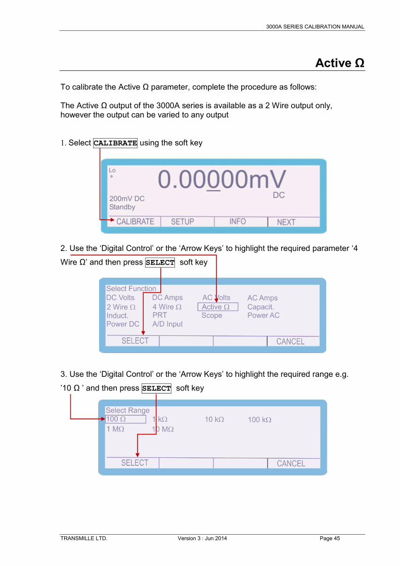
Active Ω To calibrate the Active Ω parameter, complete the procedure as follows: The Active Ω output of the 3000A series is available as a 2 Wire output only, however the output can be varied to any output 1. Select CALIBRATE using the soft key 2. Use the ‘Digital Control’ or the ‘Arrow Keys’ to highlight the required parameter ‘4
Wire Ω’ and then press SELECT soft key
3. Use the ‘Digital Control’ or the ‘Arrow Keys’ to highlight the required range e.g.
’10 Ω ’ and then press SELECT soft key

3000A SERIES CALIBRATION MANUAL
TRANSMILLE LTD. Version 3 : Jun 2014 Page 46
3. The Calibrator will now change to the 100 Ω Active Resistance range. Using the
Range up / Range Down keys, select the ‘Zero Calibration’ adjustment point
4. Connect the calibrator Voltage output terminals (Active Resistance output) Ensure that the multimeter has been zeroed with the leads shorted. If applicable use low current resistance (Low I) measurement modes. This is because active resistance is a lower accuracy output typically used for calibration of 3 ½ and 4 ½ digit multimeters that use lower measurement currents. 5. Press and measure the output.
6. To adjust the output enter the value as measured on the multimeter
E.g. measured output = 29.95 Ω, use the function control keys 5. The output can also be adjusted by moving the ‘cursor’ to the required digit and
adjusting the output using the up / down arrows or the digital control
OUTPUT ON
9 •
9
5 ENTER 2

3000A SERIES CALIBRATION MANUAL
TRANSMILLE LTD. Version 3 : Jun 2014 Page 47
6. The ‘SHIFT’ key will illuminate to indicate that a change has been made
to the calibration of the instrument, however has not yet been stored. 7. To undo the adjustment before storing the changes, press the UNDO soft key
This will remove any changes that have been made to the output of the calibrator.
7. Measure and check the output again and then press STORE soft key The following 2 screens are displayed briefly to confirm that the calibration factors have been saved.
After displaying these messages, the shift key will also cease to be illuminated
SHIFT
SHIFT
Note: All the calibration points can be adjusted prior to storing the calibration factors (STORE), however if the calibration routine is ended or there is a power failure the new calibration factors will not be saved if STORE has not been pressed.

3000A SERIES CALIBRATION MANUAL
TRANSMILLE LTD. Version 3 : Jun 2014 Page 48
Press the Range Up / Range Down keys until ‘Full Scale Calibration’ is displayed Measure the output, and adjust as required using the steps previously described. If the ‘Full Scale Calibration’ has been adjusted, ensure that the ‘Zero Calibration’ point is still in calibration. It may require more than one cycle of adjusting the Zero and Full Scale calibration points to bring both points into specification. 56. When calibration of this range is complete press the RANGE soft key, Select ‘Active Ω’, and then select the required range. 57. The ’10 Ω’, ‘100 Ω,‘1 kΩ’, ’10 kΩ’, ‘100 kΩ’, ’1 MΩ’ and ‘10 MΩ’ ranges are calibrated in the same manner.

3000A SERIES CALIBRATION MANUAL
TRANSMILLE LTD. Version 3 : Jun 2014 Page 49
Capacitance To calibrate the Capacitance parameter, complete the procedure as follows: NOTE : The Capacitance output from the 3000A series calibrator is a passive output. This means that the value on the display is the capacitance value generated at the terminals. The capacitance cannot be ‘altered’ to a different output, the value stored is simply the value of the capacitor and the connections to the terminal. 1. Select CALIBRATE using the soft key 2. Use the ‘Digital Control’ or the ‘Arrow Keys’ to highlight the required parameter
‘Capacit.’ and then press SELECT soft key
3. Use the ‘Digital Control’ or the ‘Arrow Keys’ to highlight the required range e.g.
’1uF ’ and then press SELECT soft key

3000A SERIES CALIBRATION MANUAL
TRANSMILLE LTD. Version 3 : Jun 2014 Page 50
3. The Calibrator will now change to the 1uF Capacitance range.
4. Connect the calibrator Voltage (Capacitance) terminals to the LCR Bridge. To ensure an accurate measurement connect as a 4 wire measurement, with both positive leads connected together. Ensure that the LCR Bridge is nulled before connecting to the Calibrator 5. Press and measure the output.
6. To adjust the output enter the value as measured on the multimeter
E.g. measured output = 1.0016 uF, use the function control keys 5. The output can also be adjusted by moving the ‘cursor’ to the required digit and
adjusting the output using the up / down arrows or the digital control
OUTPUT ON
1 •
0
0 1 6 ENTER

3000A SERIES CALIBRATION MANUAL
TRANSMILLE LTD. Version 3 : Jun 2014 Page 51
6. The ‘SHIFT’ key will illuminate to indicate that a change has been made
to the calibration of the instrument, however has not yet been stored. 7. To undo the adjustment before storing the changes, press the UNDO soft key
This will remove any changes that have been made to the output of the calibrator.
7. Measure and check the output again and then press STORE soft key The following 2 screens are displayed briefly to confirm that the calibration factors have been saved.
After displaying these messages, the shift key will also cease to be illuminated
SHIFT
SHIFT
Note: All the calibration points can be adjusted prior to storing the calibration factors (STORE), however if the calibration routine is ended or there is a power failure the new calibration factors will not be saved if STORE has not been pressed.

3000A SERIES CALIBRATION MANUAL
TRANSMILLE LTD. Version 3 : Jun 2014 Page 52
56. When calibration of this range is complete press the RANGE soft key, Select ‘2 Wire Ω’, and then select the required range. 57. The ‘1nF’, ‘10nF’, ‘20nF’, ‘50nF’, ‘100nF’, ‘10uF’ and ‘100uF’ ranges are calibrated in the same manner. The 1mF and 10mF ranges are simulated

3000A SERIES CALIBRATION MANUAL
TRANSMILLE LTD. Version 3 : Jun 2014 Page 53
Frequency Output Information to be added in next revision of Calibration manual. Please note that there is no adjustment of the frequency output available from the front panel, this is adjusted manually on the top board of the calibrator.

3000A SERIES CALIBRATION MANUAL
TRANSMILLE LTD. Version 3 : Jun 2014 Page 54
Inductance To calibrate the Capacitance parameter, complete the procedure as follows: NOTE : The Inductance output from the 3000A series calibrator is a passive output. This means that the value on the display is the Inductance value generated at the terminals. The Inductance cannot be ‘altered’ to a different output, the value stored is simply the value of the inductor and the connections to the terminal. 1. Select CALIBRATE using the soft key 2. Use the ‘Digital Control’ or the ‘Arrow Keys’ to highlight the required parameter
‘Capacit.’ and then press SELECT soft key
3. Use the ‘Digital Control’ or the ‘Arrow Keys’ to highlight the required range e.g.
’100mH ’ and then press SELECT soft key

3000A SERIES CALIBRATION MANUAL
TRANSMILLE LTD. Version 3 : Jun 2014 Page 55
3. The Calibrator will now change to the 100mH Inductance range.
4. Connect the calibrator Voltage (Inductance) terminals to the LCR Bridge. To ensure an accurate measurement connect as a 4 wire measurement, with both positive leads connected together. Ensure that the LCR Bridge is nulled before connecting to the Calibrator 5. Press and measure the output.
6. To adjust the output enter the value as measured on the multimeter
E.g. measured output = 100.65 mH, use the function control keys 5. The output can also be adjusted by moving the ‘cursor’ to the required digit and
adjusting the output using the up / down arrows or the digital control
OUTPUT ON
0 0
•
6 5 ENTER 1

3000A SERIES CALIBRATION MANUAL
TRANSMILLE LTD. Version 3 : Jun 2014 Page 56
6. The ‘SHIFT’ key will illuminate to indicate that a change has been made
to the calibration of the instrument, however has not yet been stored. 7. To undo the adjustment before storing the changes, press the UNDO soft key
This will remove any changes that have been made to the output of the calibrator.
7. Measure and check the output again and then press STORE soft key The following 2 screens are displayed briefly to confirm that the calibration factors have been saved.
After displaying these messages, the shift key will also cease to be illuminated
SHIFT
SHIFT
Note: All the calibration points can be adjusted prior to storing the calibration factors (STORE), however if the calibration routine is ended or there is a power failure the new calibration factors will not be saved if STORE has not been pressed.

3000A SERIES CALIBRATION MANUAL
TRANSMILLE LTD. Version 3 : Jun 2014 Page 57
56. When calibration of this range is complete press the RANGE soft key, Select ‘2 Wire Ω’, and then select the required range. 57. The ‘1mH’, ‘10mH’,’19mH’,’29mH’,’50mH’, ‘1H’ and ‘10H’ ranges are calibrated in the same manner.

3000A SERIES CALIBRATION MANUAL
TRANSMILLE LTD. Version 3 : Jun 2014 Page 58
PRT To calibrate the Capacitance parameter, complete the procedure as follows: NOTE : The PRT output from the 3000A series calibrator is a passive output. This means that the value on the display is the Temperature (Based on R0=100) value generated at the terminals. The Temperature value cannot be ‘altered’ to a different output, the value stored is simply the value of the resistor and the connections to the terminal. 1. Select CALIBRATE using the soft key 2. Use the ‘Digital Control’ or the ‘Arrow Keys’ to highlight the required parameter
‘PRT’ and then press SELECT soft key
3. Use the ‘Digital Control’ or the ‘Arrow Keys’ to highlight the required range e.g.
’PRT 100 °C ’ and then press SELECT soft key

3000A SERIES CALIBRATION MANUAL
TRANSMILLE LTD. Version 3 : Jun 2014 Page 59
3. The Calibrator will now change to the 100 °C PRT range.
4. Connect the calibrator Voltage and Current terminals to the precision Multimeter using 4 wire connection methods. If available, set the reference multimeter to Temperature mode, otherwise use lookup tables to convert the indicated resistance to temperature. 5. Press and measure the output.
6. To adjust the output enter the value as measured on the multimeter
E.g. measured output = 100.013 °C, use the function control keys 5. The output can also be adjusted by moving the ‘cursor’ to the required digit and
adjusting the output using the up / down arrows or the digital control
OUTPUT ON
0 0
•
0 1 ENTER 1 3

3000A SERIES CALIBRATION MANUAL
TRANSMILLE LTD. Version 3 : Jun 2014 Page 60
6. The ‘SHIFT’ key will illuminate to indicate that a change has been made
to the calibration of the instrument, however has not yet been stored. 7. To undo the adjustment before storing the changes, press the UNDO soft key
This will remove any changes that have been made to the output of the calibrator.
7. Measure and check the output again and then press STORE soft key The following 2 screens are displayed briefly to confirm that the calibration factors have been saved.
After displaying these messages, the shift key will also cease to be illuminated
SHIFT
SHIFT
Note: All the calibration points can be adjusted prior to storing the calibration factors (STORE), however if the calibration routine is ended or there is a power failure the new calibration factors will not be saved if STORE has not been pressed.
3000A SERIES CALIBRATION MANUAL
TRANSMILLE LTD. Version 3 : Jun 2014 Page 61
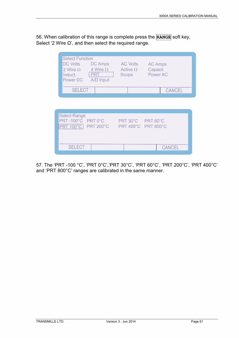
56. When calibration of this range is complete press the RANGE soft key, Select ‘2 Wire Ω’, and then select the required range. 57. The ‘PRT -100 °C’, ‘PRT 0°C’,’PRT 30°C’, ’PRT 60°C’, ’PRT 200°C’, ‘PRT 400°C’ and ‘PRT 800°C’ ranges are calibrated in the same manner.

3000A SERIES CALIBRATION MANUAL
TRANSMILLE LTD. Version 3 : Jun 2014 Page 62
Oscilloscope – Amplitude 1. Select CALIBRATE using the soft key 2. Use the ‘Digital Control’ or the ‘Arrow Keys’ to highlight the required parameter
‘Scope’ and then press SELECT soft key
3. Use the ‘Digital Control’ or the ‘Arrow Keys’ to highlight the 10mV/Div range and
then press SELECT soft key

3000A SERIES CALIBRATION MANUAL
TRANSMILLE LTD. Version 3 : Jun 2014 Page 63
3. The Calibrator will now change to the 10mV/Division Oscilloscope Amplitude
range.
4. Connect the calibrator Oscilloscope output to the precision digital multimeter. Set the 100mV DC voltage range. Normally the Oscilloscope Amplitude output is a levelled square AC Voltage output, however in the calibration mode this is set to a levelled DC waveform. This allows more accurate measurement than low level AC Voltage measurements 5. Press and measure the output.
6. To adjust the output enter the value as measured on the multimeter
E.g. measured output = 59.9985 mV, use the function control keys 5. The output can also be adjusted by moving the ‘cursor’ to the required digit and
adjusting the output using the up / down arrows or the digital control
OUTPUT ON
9 •
9
9 ENTER 5 8 5

3000A SERIES CALIBRATION MANUAL
TRANSMILLE LTD. Version 3 : Jun 2014 Page 64
6. The ‘SHIFT’ key will illuminate to indicate that a change has been made
to the calibration of the instrument, however has not yet been stored. 7. To undo the adjustment before storing the changes, press the UNDO soft key
This will remove any changes that have been made to the output of the calibrator.
7. Measure and check the output again and then press STORE soft key The following 2 screens are displayed briefly to confirm that the calibration factors have been saved.
After displaying these messages, the shift key will also cease to be illuminated
SHIFT
SHIFT
Note: All the calibration points can be adjusted prior to storing the calibration factors (STORE), however if the calibration routine is ended or there is a power failure the new calibration factors will not be saved if STORE has not been pressed.

3000A SERIES CALIBRATION MANUAL
TRANSMILLE LTD. Version 3 : Jun 2014 Page 65
When calibration of this range is complete press the RANGE soft key, The Oscilloscope Amplitude output has two calibration points to be adjusted, the 10mV/Div output and the 100mV/Div output. 2. Use the ‘Digital Control’ or the ‘Arrow Keys’ to highlight the required parameter
‘Scope’ and then press SELECT soft key
3. Use the ‘Digital Control’ or the ‘Arrow Keys’ to highlight the 100mV/Div range and
then press SELECT soft key
3. The Calibrator will now change to the 100mV/Division Oscilloscope Amplitude
range.

3000A SERIES CALIBRATION MANUAL
TRANSMILLE LTD. Version 3 : Jun 2014 Page 66
5. Press and measure the output.
If required, adjust the output as previously described, either typing in the measured value or deviating the output of the calibrator using the cursor and the arrow keys / digital control. To complete the calibration, press the STORE key
OUTPUT ON

3000A SERIES CALIBRATION MANUAL
TRANSMILLE LTD. Version 3 : Jun 2014 Page 67
Oscilloscope – Bandwidth 1. Select CALIBRATE using the soft key 2. Use the ‘Digital Control’ or the ‘Arrow Keys’ to highlight the required parameter
‘Scope’ and then press SELECT soft key
3. Use the ‘Digital Control’ or the ‘Arrow Keys’ to highlight the required parameter
‘Bandwidth’ and then press SELECT soft key

3000A SERIES CALIBRATION MANUAL
TRANSMILLE LTD. Version 3 : Jun 2014 Page 68
3. The Calibrator will now change to the Scope Bandwidth Function. Use the Range
Up / Range Down keys to select the required Scope Bandwidth adjustment point
The currently selected adjustment point is displayed on the screen above
the soft key menu
4. Connect oscilloscope to the SCOPE terminal on the front panel. Ensure that the oscilloscope is set to 50 Ohm input impedance 5. Set the oscilloscope to 100mV/Division 5. Press and measure the output.
6. To adjust the output enter the value as measured on the oscilloscope
E.g. measured output = 610.00 mV, use the function control keys 5. The output can also be adjusted by moving the ‘cursor’ to the required digit and
adjusting the output using the up / down arrows or the digital control
6 1 0 •
0 0 ENTER
OUTPUT ON

3000A SERIES CALIBRATION MANUAL
TRANSMILLE LTD. Version 3 : Jun 2014 Page 69
6. The ‘SHIFT’ key will illuminate to indicate that a change has been made
to the calibration of the instrument, however has not yet been stored.
7. To undo the adjustment before storing the changes, press the UNDO soft key
This will remove any changes that have been made to the output of the calibrator.
7. Measure and check the output again and then press STORE soft key The following 2 screens are displayed briefly to confirm that the calibration factors have been saved.
After displaying these messages, the shift key will also cease to be illuminated
SHIFT
SHIFT
Note: All the calibration points can be adjusted prior to storing the calibration factors (STORE), however if the calibration routine is ended or there is a power failure the new calibration factors will not be saved if STORE has not been pressed.

3000A SERIES CALIBRATION MANUAL
TRANSMILLE LTD. Version 3 : Jun 2014 Page 70
8. Use the ‘range up’ and ‘range down’ keys to change the calibration point to
Scope BW 10MHz.
10. Adjust as steps ASJDASJDASDJ.
11. Continue adjustment until 260MHZ (SCP250) / 360MHz (SCP350) / 620MHz (SCP600) point has been adjusted
12. Verify Bandwidth Output flatness by performing a sweep of the full frequency
range, ensuring that flatness is achieved across the full range of the oscilloscope function.

3000A SERIES CALIBRATION MANUAL
TRANSMILLE LTD. Version 3 : Jun 2014 Page 71
AC Power (Current Output) 1. Select CALIBRATE using the soft key 2. Use the ‘Digital Control’ or the ‘Arrow Keys’ to highlight the required parameter
‘Power AC’ and then press SELECT soft key
3. Use the ‘Digital Control’ or the ‘Arrow Keys’ to highlight the required parameter
‘200uA AC’ and then press SELECT soft key

3000A SERIES CALIBRATION MANUAL
TRANSMILLE LTD. Version 3 : Jun 2014 Page 72
3. The Calibrator will now change to the 200uA AC range. Use the Range Up /
Range Down keys to select the 60Hz Positive Full Scale adjustment point
4. Connect the calibrator output voltage terminals to the precision multimeter. Ensure that the multimeter is in AC Current on the appropriate range. Ensure that the correct terminals / current shunt is used for the various current outputs. The 3000A calibrators can output up to 30A AC current, which can blow the fuse / cause damage if the incorrect input is used 5. Press and measure the output.
6. To adjust the output enter the value as measured on the multimeter
E.g. measured output = 99.90 uA, use the function control keys 5. The output can also be adjusted by moving the ‘cursor’ to the required digit and
adjusting the output using the up / down arrows or the digital control
9 9 •
9 0 ENTER
OUTPUT ON

3000A SERIES CALIBRATION MANUAL
TRANSMILLE LTD. Version 3 : Jun 2014 Page 73
6. The ‘SHIFT’ key will illuminate to indicate that a change has been made
to the calibration of the instrument, however has not yet been stored.
7. To undo the adjustment before storing the changes, press the UNDO soft key
This will remove any changes that have been made to the output of the calibrator.
7. Measure and check the output again and then press STORE soft key The following 2 screens are displayed briefly to confirm that the calibration factors have been saved.
After displaying these messages, the shift key will also cease to be illuminated
SHIFT
SHIFT
Note: All the calibration points can be adjusted prior to storing the calibration factors (STORE), however if the calibration routine is ended or there is a power failure the new calibration factors will not be saved if STORE has not been pressed.

3000A SERIES CALIBRATION MANUAL
TRANSMILLE LTD. Version 3 : Jun 2014 Page 74
8. Use the ‘range up’ and ‘range down’ keys to change the calibration point to
60Hz ‘Zero Calibration’.
NOTE : The ‘Zero Calibration’ of the AC Current ranges is performed at 20% of full scale 9. Measure the output as before; if necessary adjust as previously described above.
11. Measure the output as before; if necessary adjust as previously described above. 56. When calibration of this range is complete press the RANGE soft key Select ‘AC Current’ and then ‘2mA AC’ and proceed with this range as described above. 57. The ’2mA AC’, ‘20mA AC’,‘200mA AC’, ‘2A AC’ and ‘30A AC’ ranges are calibrated in the same manner.

3000A SERIES CALIBRATION MANUAL
TRANSMILLE LTD. Version 3 : Jun 2014 Page 75
Remember to change the connections when calibrating the
30A range Current connections - 200A, 2mA, 20mA, 200mA and 2A ranges High current connections 30A range

3000A SERIES CALIBRATION MANUAL
TRANSMILLE LTD. Version 3 : Jun 2014 Page 76
DC Power (Current Output) 1. Select CALIBRATE using the soft key 2. Use the ‘Digital Control’ or the ‘Arrow Keys’ to highlight the required parameter
‘Power DC’ and then press SELECT soft key
3. Use the ‘Digital Control’ or the ‘Arrow Keys’ to highlight the required parameter
‘200uA DC’ and then press SELECT soft key

3000A SERIES CALIBRATION MANUAL
TRANSMILLE LTD. Version 3 : Jun 2014 Page 77
3. The Calibrator will now change to the 200uA DC range. Use the Range Up /
Range Down keys to select the Positive Full Scale adjustment point
4. Connect the calibrator output voltage terminals to the precision multimeter. Ensure that the multimeter is in DC Current on the appropriate range. Ensure that the correct terminals / current shunt is used for the various current outputs. The 3000A calibrators can output up to 30A AC current, which can blow the fuse / cause damage if the incorrect input is used 5. Press and measure the output.
6. To adjust the output enter the value as measured on the multimeter
E.g. measured output = 99.90 uA, use the function control keys 5. The output can also be adjusted by moving the ‘cursor’ to the required digit and
adjusting the output using the up / down arrows or the digital control
9 9 •
9 0 ENTER
OUTPUT ON

3000A SERIES CALIBRATION MANUAL
TRANSMILLE LTD. Version 3 : Jun 2014 Page 78
6. The ‘SHIFT’ key will illuminate to indicate that a change has been made
to the calibration of the instrument, however has not yet been stored.
7. To undo the adjustment before storing the changes, press the UNDO soft key
This will remove any changes that have been made to the output of the calibrator.
7. Measure and check the output again and then press STORE soft key The following 2 screens are displayed briefly to confirm that the calibration factors have been saved.
After displaying these messages, the shift key will also cease to be illuminated
SHIFT
SHIFT
Note: All the calibration points can be adjusted prior to storing the calibration factors (STORE), however if the calibration routine is ended or there is a power failure the new calibration factors will not be saved if STORE has not been pressed.

3000A SERIES CALIBRATION MANUAL
TRANSMILLE LTD. Version 3 : Jun 2014 Page 79
8. Use the ‘range up’ and ‘range down’ keys to change the calibration point to
‘Zero Calibration’.
9. Measure the output as before; if necessary adjust as previously described above.
11. Measure the output as before; if necessary adjust as previously described above. 56. When calibration of this range is complete press the RANGE soft key Select ‘DC Current’ and then ‘2mA ’ and proceed with this range as described above. 57. The ’2mA DC’, ‘20mA DC’,‘200mA DC’, ‘2A DC’ and ‘30DC’ ranges are calibrated in the same manner. Remember to change the connections when calibrating the
30A range

3000A SERIES CALIBRATION MANUAL
TRANSMILLE LTD. Version 3 : Jun 2014 Page 80
Current connections - 200A, 2mA, 20mA, 200mA and 2A ranges High current connections 30A range
3000A SERIES CALIBRATION MANUAL
TRANSMILLE LTD. Version 3 : Jun 2014 Page 81
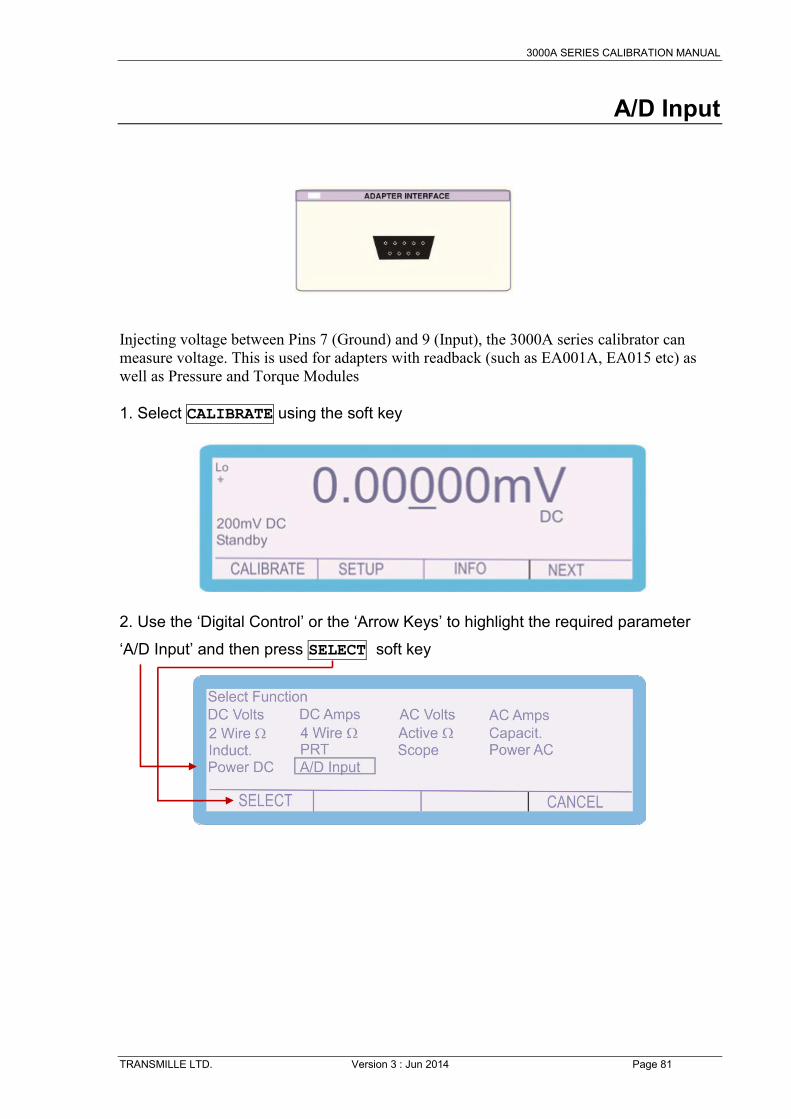
A/D Input Injecting voltage between Pins 7 (Ground) and 9 (Input), the 3000A series calibrator can measure voltage. This is used for adapters with readback (such as EA001A, EA015 etc) as well as Pressure and Torque Modules 1. Select CALIBRATE using the soft key 2. Use the ‘Digital Control’ or the ‘Arrow Keys’ to highlight the required parameter
‘A/D Input’ and then press SELECT soft key

3000A SERIES CALIBRATION MANUAL
TRANSMILLE LTD. Version 3 : Jun 2014 Page 82
3. The Calibrator will now change to the A/D Input Screen. Use the Range Up /
Range Down keys to select the Zero Calibration adjustment point
4. Apply an output of 0V from your voltage source to the adapter interface, using Pin 7 as the Ground or Negative connection, and Pin 9 as the Signal or Positive connection. 5. Wait for the reading to stabilise on the screen of the 3000A. After achieving a
stable reading, press the ‘Store’ button.
7. The following 2 screens are displayed briefly to confirm that the calibration has been saved.

3000A SERIES CALIBRATION MANUAL
TRANSMILLE LTD. Version 3 : Jun 2014 Page 83
The screen of the 3000A will now display 0V. If the reading is different, repeat the previous stages 3. Using the Range Up / Range Down keys to select the Positive Full Scale
adjustment point
4. Apply an output of 10V from your voltage source to the adapter interface, using Pin 7 as the Ground or Negative connection, and Pin 9 as the Signal or Positive connection. 5. Wait for the reading to stabilise on the screen of the 3000A. After achieving a stable reading, press the ‘Store’ button.

3000A SERIES CALIBRATION MANUAL
TRANSMILLE LTD. Version 3 : Jun 2014 Page 84
7. The following 2 screens are displayed briefly to confirm that the calibration has been saved.
The screen of the 3000A will now display 10V. If the reading is different, repeat the previous stages 3. Using the Range Up / Range Down keys, select the Negative Full Scale point, and
repeat the