3 ubiquitous communication technology for disaster ... ubiquitous communication technology for...
TRANSCRIPT

153TAKIZAWA Osamu et al.
1 Introduction
RFID, which has become a ubiquitous device, began its rapid spread at the start of the 21st century. This paper describes our research and development efforts concerning the application of RFID in disaster prevention since 2001. The results of our research and development up to FY2004 has already been reported in previous issues of the NICT Journal and elsewhere [1] [21], so this paper focuses on the results after FY2005 reported by the Disaster Management and Mitigation Group.
2 Overview of RFID
RFID is a device that incorporates wireless communication circuits and memory to enable contactless ID reading by radio wave or electro magnetic induction using a terminal, or reader. RFID is either passive, which also enables data to be written by using a terminal (writer), or active, which discontinuously transmits a fixed ID, as with a radio beacon.
Whereas active RFID requires a power source, passive RFID does not use a power source. A passive RFID enables data to be transmitted over several centimeters, while an active RFID enables data to be communicated over several meters. Compared to paper as record-ing media, passive RFID has the advantages of higher data storage density per area, the ability to read instantaneously, and ease in saving, storing, and reusing the read informa-tion as electronic data. Also, it can control the access rights of users, thereby restricting the disclosure of information to family or public safety personnel. These characteristics are regarded as useful in an information exchange device during a disaster.
3 Information sharing using RFID during a disaster
3.1 OverviewIn the event of a large-scale disaster, it is
inevitable that communication is disrupted. After the Great Hanshin earthquake, paper
3 Ubiquitous Communication Technology for Disaster Management and Mitigation
3-1 Ubiquitous Devices for Disaster Mitigation
TAKIZAWA Osamu, HOSOKAWA Masafumi, and SHIBAYAMA Akihiro
At the time of a catastrophic calamity in which a telecom infrastructure receives a serious damage, the structure which shares information electronically and carries it simply by the help is useful. RFID (Radio Frequency IDentification Tag) which is one of the ubiquitous devices is a device which enables exchange of electronic data locally, and can be utilized as data storage in the information exchange at the time of a disaster. This paper describes the research-and-devel-opment result about disaster prevention application of RFID in the Disaster Management and Mitigation Group.
KeywordsRadio Frequency IDentification, Ubiquitous, Disaster mitigation, Positioning, Cellular phone
Journal of the National Institute of Information and Communications Technology Vol. 58 Nos. 1/2 2011154
posters were widely used to transmit informa-tion in the disaster area. Safety and evacuation information as well as the results of inspec-tions of the damaged buildings were written on posters and posted directly on building walls. Consequently, information about disas-ter area exists within the affected area, which makes the collection and sharing of informa-tion using computer servers difficult, especial-ly in the event of a large-scale disaster where the communication infrastructure has been seriously damaged. For this reason, during the initial stages of disaster recovery, manually transporting information should be the only possible way. It is therefore beneficial to take measures to share the information that has been collected manually from the disaster area in an electronic format, which may help res-cue and recovery operations.
Against this background, the authors developed information-sharing technologies using RFID. Typically, RFID is used as a device to store only an ID whose meaning is acquired (resolved) from a server on the net-work, which is accessed by a terminal. How-ever, the authors aimed to use RFID as a means of data storage, such as a flash memo-ry. Passive RFID can satisfy this need because it operates without a power source on the device. Passive RFID has the drawback that it is possible to read data over a short distance. To overcome this drawback, during the early stages of development in 2001, a high-pow-ered desktop reader-writer was configured on a push car so that read-write operations could be done as much as possible when the reader-writer and RFID were separated by some dis-tance. A reader-writer that was mounted on a push car proved to have insufficient mobility, so it was modified so that it could carried on the user’s back while retaining the same con-figuration. In addition, a low-powered porta-ble reader-writer was also developed to increase mobility, even sacrificing the read-write distance. The low-powered reader-writer was designed to be compatible with the initial high-powered reader-writer, and both termi-nals used the same RFIDs [1] [2].
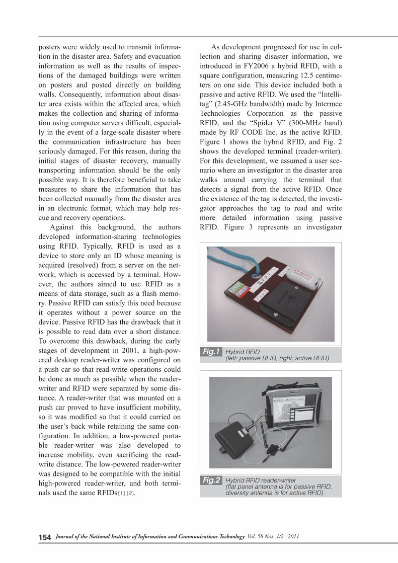
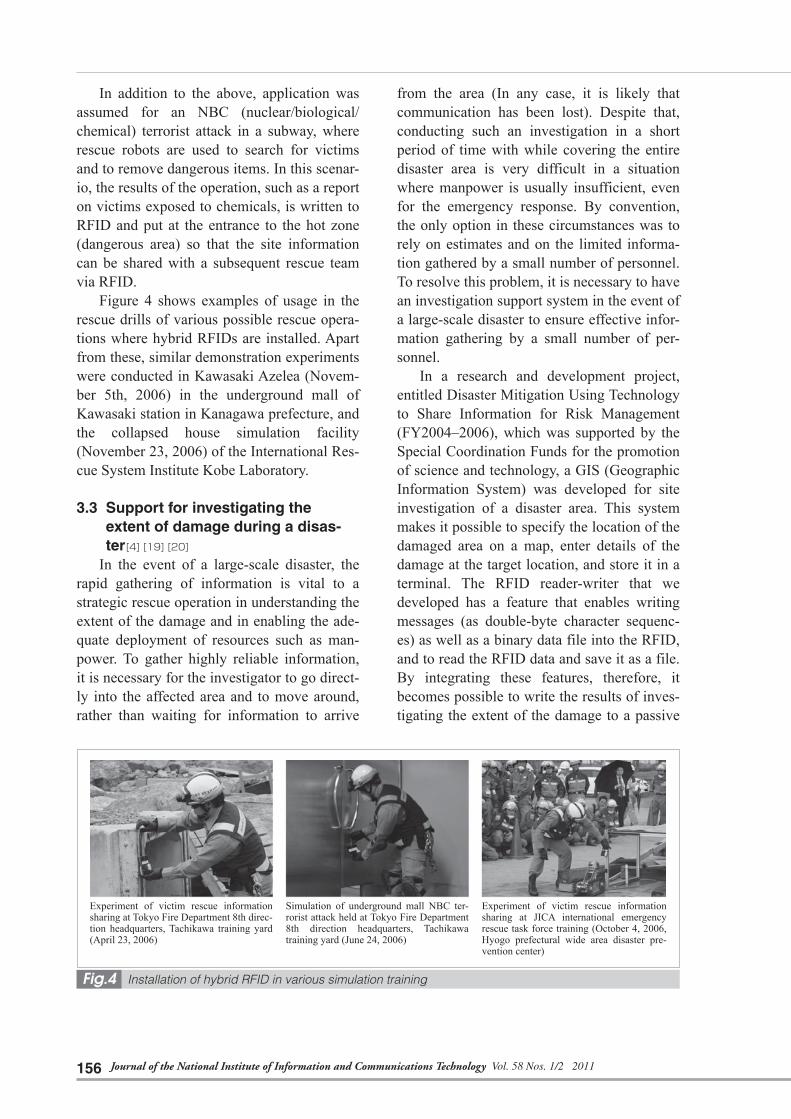
As development progressed for use in col-lection and sharing disaster information, we introduced in FY2006 a hybrid RFID, with a square configuration, measuring 12.5 centime-ters on one side. This device included both a passive and active RFID. We used the “Intelli-tag” (2.45-GHz bandwidth) made by Intermec Technologies Corporation as the passive RFID, and the “Spider V” (300-MHz band) made by RF CODE Inc. as the active RFID. Figure 1 shows the hybrid RFID, and Fig. 2 shows the developed terminal (reader-writer). For this development, we assumed a user sce-nario where an investigator in the disaster area walks around carrying the terminal that detects a signal from the active RFID. Once the existence of the tag is detected, the investi-gator approaches the tag to read and write more detailed information using passive RFID. Figure 3 represents an investigator
Fig.1 Hybrid RFID (left: passive RFID, right: active RFID)
Fig.2 Hybrid RFID reader-writer (flat panel antenna is for passive RFID, diversity antenna is for active RFID)

155TAKIZAWA Osamu et al.
holding the antenna over the passive RFID for read-write operation in a demonstration exper-iment.
During the initial stages of development, we assumed the following usage scenario: an RFID is installed as an electronic doorplate at the entrance of a building, and the residents of the building record safety and evacuation des-tination information as they evacuate the building. The reader-writer was made with functionality that enables user operation to be navigated by a synthesized voice, so that the device can be used by an operator who does not have so much technological expertise. The reader-writer was made with another feature that reads message content (double-byte char-acter sequence) aloud in a synthesized voice while it is being read from or written to a pas-sive RFID. This feature of a speech system using RFID alone was presented in various exhibitions by NICT Incubations as a unique application of RFID that can also be used as an audio guidance system, beyond the scope of disaster prevention applications. Since the message is written to the user area of the RFID as data, the terminal can convert it into speech as a stand-alone device, without having to access the network.
Based on these features, we extended our development to various technological applica-tions as we engaged in research and develop-ment projects in the field of disaster preven-tion. These applications are described in the following sections of the paper.
3.2 Support for rescue operations using RFID [3]
In FY2002, the Ministry of Education, Culture, Sports, Science and Technology (MEXT) launched the Special Project for Earthquake Disaster Mitigation in Urban Areas, which conducts research and develop-ment aimed at significantly reducing human injury and physical damage in the event of earthquake comparable to the Great Hanshin earthquake in urban area, such as Tokyo (southern Kanto) or the Keihanshin area. The project aimed at establishing a scientific and technological foundation for the prevention of disasters resulting from earthquakes. This was a large protect comprising four major catego-ries, such as optimization of the disaster response strategy, such as when rescuing disaster victims. The major categories each consisted of sixteen intermediate categories, such as development of the foundation for the next generation disaster prevention tech-niques, such as a rescue robot. One of the sub-ordinate categories under this intermediate category was the development of an emergen-cy information collection system using RFID. This subordinate category was assigned to NICT, for which we embarked on the study of information gathering and sharing via RFID.
In this project, we strived to apply RFID technologies to information sharing among members of the rescue team. As an example of shared information, we assumed rescue infor-mation concerning victims in collapsed build-ings. More precisely, during a search and res-cue operation for victims trapped inside col-lapsed buildings, the rescue member logs his or her operation in the RFID. The next rescue worker then reads this operation log left at the rescue site before preparing an operation plan. This procedure eliminates the duplication of unnecessary rescue steps, and provides infor-mation about the rescued victims, such as the extent of their injuries and the hospital to which they have been taken. In this case, the use of RFID instead of paper posters enables information access to be controlled, and thus personal information to be handled safely.
Fig.3 Usage of hybrid RFID reader-writer
Journal of the National Institute of Information and Communications Technology Vol. 58 Nos. 1/2 2011156
In addition to the above, application was assumed for an NBC (nuclear/biological/chemical) terrorist attack in a subway, where rescue robots are used to search for victims and to remove dangerous items. In this scenar-io, the results of the operation, such as a report on victims exposed to chemicals, is written to RFID and put at the entrance to the hot zone (dangerous area) so that the site information can be shared with a subsequent rescue team via RFID.
Figure 4 shows examples of usage in the rescue drills of various possible rescue opera-tions where hybrid RFIDs are installed. Apart from these, similar demonstration experiments were conducted in Kawasaki Azelea (Novem-ber 5th, 2006) in the underground mall of Kawasaki station in Kanagawa prefecture, and the collapsed house simulation facility (November 23, 2006) of the International Res-cue System Institute Kobe Laboratory.
3.3 Support for investigating the extent of damage during a disas-ter [4] [19] [20]
In the event of a large-scale disaster, the rapid gathering of information is vital to a strategic rescue operation in understanding the extent of the damage and in enabling the ade-quate deployment of resources such as man-power. To gather highly reliable information, it is necessary for the investigator to go direct-ly into the affected area and to move around, rather than waiting for information to arrive
from the area (In any case, it is likely that communication has been lost). Despite that, conducting such an investigation in a short period of time with while covering the entire disaster area is very difficult in a situation where manpower is usually insufficient, even for the emergency response. By convention, the only option in these circumstances was to rely on estimates and on the limited informa-tion gathered by a small number of personnel. To resolve this problem, it is necessary to have an investigation support system in the event of a large-scale disaster to ensure effective infor-mation gathering by a small number of per-sonnel.
In a research and development project, entitled Disaster Mitigation Using Technology to Share Information for Risk Management (FY2004–2006), which was supported by the Special Coordination Funds for the promotion of science and technology, a GIS (Geographic Information System) was developed for site investigation of a disaster area. This system makes it possible to specify the location of the damaged area on a map, enter details of the damage at the target location, and store it in a terminal. The RFID reader-writer that we developed has a feature that enables writing messages (as double-byte character sequenc-es) as well as a binary data file into the RFID, and to read the RFID data and save it as a file. By integrating these features, therefore, it becomes possible to write the results of inves-tigating the extent of the damage to a passive
Fig.4 Installation of hybrid RFID in various simulation training
Experiment of victim rescue information sharing at Tokyo Fire Department 8th direc-tion headquarters, Tachikawa training yard (April 23, 2006)
Simulation of underground mall NBC ter-rorist attack held at Tokyo Fire Department 8th direction headquarters, Tachikawa training yard (June 24, 2006)
Experiment of victim rescue information sharing at JICA international emergency rescue task force training (October 4, 2006, Hyogo prefectural wide area disaster pre-vention center)

157TAKIZAWA Osamu et al.
RFID and to leave the information at the disaster site. Also, by using a passive RFID reader, it becomes possible to read the damage information that has already been written to the RFID. A passive RFID reader-writer is incorporated as a plug-in for the application that was designed for the on-site investigation of damage, so the reader-writer can be started from this application. As shown in Fig. 5, the data input window used in the RFID read-write operation appears on top of the on-site investigation application window.
To evaluate this application, we conducted an experiment to gather information on disas-ter damage, by incorporating the system in a disaster prevention drill performed on Septem-ber 4, 2005, in 5 Chome Kami-Jujyo, Kita-ku, Tokyo Metropolitan Government. This experi-ment virtually assumed three fires, 15 building collapses and three road closures in a town occupying an area of 500 square meters. At each disaster site, signage with a passive RFID was installed. A participant in the exper-iment who carried an investigation terminal determined the extent of the damage (damage assessment result and the number of victims needing to be rescued) from information stat-ed on the signage, and stored it in the RFID. Another participant then collected this infor-mation by reading from the RFID and consoli-dating the information at the disaster head-quarters. The effectiveness of this process was compared to a case where a paper map was
used to gather information. Figure 6 represents the experiment. A black square at the right bottom of the signage is the passive RFID. In the experiment, the system could operate almost as intended by design, except for fail-ures caused by user mistakes.
A similar experiment was conducted on November 20 in Toyohashi-shi, Aichi prefec-ture.
The results of these field experiments indi-cated that there was a need for the RFID to be easily found by investigators when it was put at the disaster site. To meet this requirement, we added a function for receiving an ID trans-mitted by an active RFID by using the hybrid RFID described earlier in this paper. Also, we designed the terminal to make a beep sound when it received an active RFID so that a res-cuer could quickly find the RFID on-site. We also developed a feature to depict on the GIS the estimated distance from the terminal by measuring the field intensity of the active RFID. The distance was represented on the GIS as a circle centered on the terminal’s own location positioned by GPS. Figure 7 is a screen shot of this enhanced GIS. This feature enabled rescuers to rapidly find the RFID locations during the investigation.
A similar experiment was conducted using this enhanced terminal on November 3, 2006, again in a disaster prevention drill at 5 Chome Kami-Jyujo, Kita-ku, Tokyo Metropolitan Government. Figure 8 represents this experi-
Fig.5 Screen for on-site investigation of disaster damage situation
Fig.6 Experiment in disaster prevention drill at 5 chome Kami-Jujo, Kita-ku Tokyo Metropolitan Government (September 4, 2005)

Journal of the National Institute of Information and Communications Technology Vol. 58 Nos. 1/2 2011158
ment. In the image at the left, a hybrid RFID is attached to the right side of the signage with adhesive tape. With the new terminal, it was possible to detect the RFID fastened to the installed location as well as the RFID that the rescuer, who was moving around, hung around his neck (Fig. 8, right). This result confirmed that the effectiveness of RFID detection was improved as expected.
Development of the hybrid RFID system and the above experiment were reported at the System Integration Division Conference (SI2006) of the Society of Instrument and Control Engineers [5], and received the Presen-tation Excellence Award. Initially in this ter-minal, the active RFID was simply considered as a marker to notify rescuers of the existence of the passive RFID. Our next step was to equip the active RFID with a feature to trans-mit its absolute location information through the use of positioning by active RFID in plac-es where GPS positioning was difficult.
Figure 9 is a screen shot of the application
with the feature for acquiring the terminal’s position by using location information obtained from GPS or active RFID. When a GPS signal is received, the location of the ter-minal (latitude and longitude) is positioned by GPS and displayed at top right of the display window. When an active RFID is received, the terminal refers to a built-in location resolution table (MS Access format), converts the ID to latitude and longitude, then displays the loca-tion of the terminal (ID and its associated lati-tude and longitude) in the right center of the display window. Using active RFID as a source of latitude and longitude information enabled disaster investigation to become avail-able while the investigator was aware of his terminal’s absolute position, both in an out-door location where a GPS signal could be received, as well in a closed space, such as underground mall, where GPS signal recep-tion was poor.
This application requires that a built-in location resolution table is stored before use so that the ID of the active RFID can be con-verted into latitude and longitude. The appli-cation was therefore not practical in the case of a site that had never been visited. The next enhancement enabled this location resolution table to be stored on the server (location reso-lution server) accessed via the Internet. The terminal was equipped with a mobile commu-nication card, and the terminal was able to
Fig.7 GIS screen enabled by feature to indi-cate estimated location of active RFID by a circle centered on terminal’s own location
Fig.8 Experiment in disaster prevention drill at 5 chome Kami-Jujo, Kita-ku Tokyo Metropolitan Government (September 3, 2006)
Fig.9 GIS screen enabled by feature to indi-cate terminal’s own location retrieved by GPS or active RFID

159TAKIZAWA Osamu et al.
resolve its location by accessing the network. Figure 10 is a screen shot of the enhanced GIS. The result of GPS positioning or RFID positioning is shown in the right side of the display window. The RFID positioning result is shown as a set consisting of the following information: received ID, the latitude and lon-gitude returned by the location resolution server to which the received ID is sent, the location name, the address and so on. In addi-tion, the window below displays the URL that corresponds to the area where the received ID exists. When the user presses the Display Link URL button, a web browser starts and displays the content retrieved by this URL. If the IDs of multiple tags are received, the first received ID is processed and the second and subsequent IDs are ignored. The location resolution server described in this section is also used in Chap-ter 4, as the server used for cell phone posi-tioning using RFID.
4 Cooperation of cell phone termi-nal and RFID
4.1 OverviewCell phones are extensively used commu-
nication devices, so it is important to consider using it in combination with RFID. Cell phone terminals equipped with a built-in passive RFID are already in practical use as electronic money and as electronic tickets for use on public transport. In contrast, cell phone termi-nals that incorporate RFID readers are just
now becoming technically practical. KDDI Corporation created prototypes of two cell phones: one that has a built-in reader of active RFIDs and one that has a built-in reader of passive RFIDs [6]. NTT DoCoMo Inc. has been promoting research into reducing power consumption so that active RFID readers can be incorporated in cell phone terminals [7].
First, a means of connecting a cell phone terminal with a unrewritable (read-only) pas-sive RFID reader as an external device became available [8]. This consisted of E03CA, an au cell phone terminal, and a 2.45-GHz bandwidth passive RFID reader (HE-MU380-SH11, Mu-Chip reader produced by Hitachi Ltd.), which was connected by an attachment (Fig. 11).
Furthermore, if the cell phone terminal is equipped with Bluetooth communication func-tionality, Bluetooth devices can be dealt with as a type of active RFID by using the device address as the ID. Therefore, the authors developed an application on a cell phone ter-minal that uses the small wireless acceleration sensor (WAA-001 produced by Wireless Tech-nologies, Inc.) shown in Fig. 12 for its Blue-tooth communication feature to be used as an active RFID.
Moreover, a small RFID reader-writer module with low power consumption intended for cell phones was developed through research under contract, entitled A Study on Ubiquitous Platform Technology [9] by the Ministry of Internal Affairs and Communica-
Fig.10 GIS screen enabled by access fea-ture to location resolution server
Fig.11 Cell phone terminal equipped with passive RFID reader attachment (au E03CA)

Journal of the National Institute of Information and Communications Technology Vol. 58 Nos. 1/2 2011160
tions. In FY2010, a cell phone terminal with embedded UHF band RFID reader-writer was developed (au E05SH) [10].
In this section, we describe RFID position-ing and information sharing that uses RFID as data storage that are enabled on the cell phone platform using devices developed above.
4.2 Cell phone positioning using RFID [11]
Location information services that make use of satellite positioning technologies have come into widespread use, together with the extensive use of cellular devices such as cell phones. Nevertheless, problems have emerged, such as the existence of areas where location information cannot be obtained by GPS or where there is poor positioning accu-racy. Therefore, a research and development project, entitled RFID-based Positioning Sys-tems for Enhancing Safety and Sense of Secu-rity, was commenced in FY2006 and contin-ued for three years with the support of the Special Coordination Funds for the promotion of science and technology. A characteristic of this project was the cross-ministry effort that was made, since the project belonged to the Coordination Program of Science and Tech-nology Projects, which are being promoted through inter-ministry cooperation due to its national and social importance. The principal researcher was Associate Professor Kaoru
Sezaki from the Center for Spatial Information Science at the University of Tokyo. Partici-pants were the Ministry of Land, Infrastruc-ture, Transport and Tourism, the Geographical Survey Institute, the Ministry of Internal Affairs and Communications, the Fire and Disaster Man-agement Agency (Fire Service Technology Policy Office and National Research Institute of Fire and Disaster), the National Police Agency, the National Research Institute of Police Science, and NICT.
Most location-aware technologies or trace-ability technologies realized by RFID are used in configurations where the RFID is attached to movable entities, such as people or materi-als, RFID receivers that are connected to a network are installed at fixed locations, and the location information is controlled by a server in a coordinated manner. Unlike these technologies, this project strived to achieve a unique system in which the RFID is installed as a location marker in an environment, while people carry the terminal that has RFID receiver functionality. This configuration has the benefit of low infrastructure costs.
RFID positioning is enabled by mobile ter-minals that receive the ID from an RFID installed in the environment. The location res-olution server is accessed through the network and the location of the ID is queried and retrieved as the location of the terminal. This means that the positioning accuracy of the ter-minal’s location depends on the reading dis-tance of the ID. Also, it is prerequisite that the location information for ID is registered in the location resolution server.
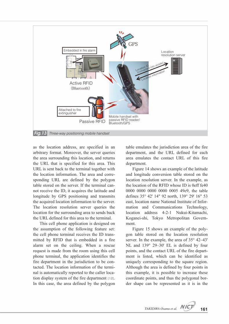
Figure 13 shows the operation of the RFID positioning application we developed. The ter-minal shown in Fig. 11 in Section 4.1 is used. The terminal reads the passive RFID or Blue-tooth device address and transmits the ID to the location resolution server. The server que-ries the location information that corresponds to the sent ID, and it returns the retrieved loca-tion information to the terminal. The location information is defined for each ID in the lati-tude and longitude conversion table stored on the server. The latitude and longitude, as well
Fig.12 Bluetooth device (small size wireless acceleration sensor) used instead of active RFID
161TAKIZAWA Osamu et al.
as the location address, are specified in an arbitrary format. Moreover, the server queries the area surrounding this location, and returns the URL that is specified for this area. This URL is sent back to the terminal together with the location information. The area and corre-sponding URL are defined by the polygon table stored on the server. If the terminal can-not receive the ID, it acquires the latitude and longitude by GPS positioning and transmits the acquired location information to the server. The location resolution server queries the location for the surrounding area to sends back the URL defined for this area to the terminal.
This cell phone application is designed on the assumption of the following feature set: the cell phone terminal receives the ID trans-mitted by RFID that is embedded in a fire alarm set on the ceiling. When a rescue request is made from the room using this cell phone terminal, the application identifies the fire department in the jurisdiction to be con-tacted. The location information of the termi-nal is automatically reported to the caller loca-tion display system of the fire department [12]. In this case, the area defined by the polygon
table emulates the jurisdiction area of the fire department, and the URL defined for each area emulates the contact URL of this fire department.
Figure 14 shows an example of the latitude and longitude conversion table stored on the location resolution server. In the example, as the location of the RFID whose ID is 0eff fe40 0000 0000 0000 0000 0005 49e9, the table defines 35° 42' 14" 92 north, 139° 29' 16" 53 east, location name National Institute of Infor-mation and Communications Technology, location address 4-2-1 Nukui-Kitamachi, Koganei-shi, Tokyo Metropolitan Govern-ment.
Figure 15 shows an example of the poly-gon table stored on the location resolution server. In the example, the area of 35° 42–43' NL and 139° 29–30' EL is defined by four points, and the contact URL of the fire depart-ment is listed, which can be identified as uniquely corresponding to the square region. Although the area is defined by four points in this example, it is possible to increase these coordinate points, and thus the polygonal bor-der shape can be represented as it is in the
Fig.13 Three-way positioning mobile handset
Active RFID
Attached to fire extinguisher
Embedded in fire alarm
Passive RFIDMobile handset with passive RFID reader/Bluetooth/GPS
Location resolution server
Location ID
(converted into ucode)
Location information

Journal of the National Institute of Information and Communications Technology Vol. 58 Nos. 1/2 2011162
actual map. If the area defined by the polygon table includes the ID location defined by the latitude and longitude conversion table, and the terminal receives this ID, the URL defined for this area is returned from the location reso-lution server. When the terminal accesses this URL, for example, the contact screen appears to enable connection to the fire department in this area.
Having a location resolution server on the network enables the RFID transmission data to be reduced to the ID only, thereby minimiz-ing the required memory capacity. Location information can be uniformly managed by the server, which simplifies maintenance. Howev-er, location resolution becomes unavailable when a network failure occurs, such as in the event of a disaster.
4.3 Information sharing feature using an RFID as data storage [13]
Our objective was to achieve the informa-tion sharing feature as described in Chapter 3 on the cell phone platform as well. In normal times, it can serve to offer limited local infor-
mation, instead of conventional paper posters or message boards. For example, it can pro-vide valuable information that can be exclu-sively accessed by people who visit a location. It can function as a guest book or as pilgrims’ slips in tourist locations, such as temples and shrines, or as a stamp rally. In the event of a large-scale disaster when cell phone communi-cation is lost, it is intended that information is exchange via RFID, as described in Chapter 3.
Before the cell phone equipped with an RFID reader-writer in the UHF band was developed in FY2010, as described in Section 4.1, there was no available cell phone termi-nal that allowed date to be written directly to an RFID. Writing to an RFID was virtually realized by use of the cell phone terminal with a read-only passive RFID reader attachment, as shown in Fig. 11 in Section 4.1. Due to the read-only attribute, information that was read or written was designed to be stored as a mes-sage under the automatically created thread associated with the ID on a web-based BBS (Bulletin Board System). More simply, the passive RFID in the RFID application for positioning described in Section 4.2 was mod-ified to specify the BBS thread in this feature, instead of being used for positioning. There-fore, a similar feature can be realized through the use of two-dimensional code, such as a QR code instead of RFID.
The procedure for writing information is as follows: When an ID is received from a passive RFID, the cell phone terminal trans-mits the ID to BBS. The input screen is then displayed to write the information. If a thread that corresponds to the ID already exists, the information input from the screen is written as a new message under the existing thread. If a corresponding thread does not exist, a new thread is created and the information input from the screen is written. If network access is not available when the data is written, an input screen appears to save message in the termi-nal. The stored messages are sent to the BBS when network access becomes available. In this manner, by virtually enabling the write operation while offline, we intended a user
Fig.15 Example of polygon table
Fig.14 Example of latitude and longitude con-version table

163TAKIZAWA Osamu et al.
experience that is closer to the real usage to directly write information to the device. The written information consisted of the following: the message that the user entered from the ter-minal, the time at which the message was written, location information acquired by the Bluetooth device or by GPS positioning, as described in Section 4.2, and auxiliary infor-mation received from the location resolution server.
The procedure for reading the information is as follows: Upon receipt of an ID from the passive RFID, the cell phone terminal access-es BBS, displays the thread that corresponds to the ID, and selects and displays the message written. If no network access is available, the read operation cannot be preformed.
After a cell phone terminal with an embed-ded RFID reader-writer of the UHF-band was developed in FY2010 [10], we developed an application feature for writing messages to the actual RFID, not to the BBS. Figure 16 repre-sents the operation.
In this application, a character sequence can be entered by using the numeric keys on cell phones so as to create a text mail mes-sage. The write operation is executed by hold-ing a cell phone over the passive RFID (Mu-Chip Hibiki) with a 950-MHz bandwidth. Once the read operation is executed, the char-acter sequence written in the user area of RFID is displayed on the screen. It is possible to select whether all or part of a message is read, and the part to be read is specified by the
starting byte of the selected message. Figure 17 shows the screen shot of the input display.
5 Development of generic RFID terminal
5.1 Overview [14]
Establishing compatibility is one of the challenges of an RFID system. Most conven-tional RFID systems were developed without assuming interoperability with other systems, and this is considered a reason for them not being in widespread use. In this section, we describe the generic RFID terminal developed under the project entitled RFID-based Posi-tioning Systems for Enhancing Safety and Sense of Security.
5.2 Integrated reader-writer that sup-ports multiple RFIDs [15]
In the project, RFID-based Positioning Systems for Enhancing Safety and Sense of Security, six types of RFID were used, as shown in Table 1. In this paper, each RFID type is hereinafter represented by and identifi-er (RFID 1 through 6) shown in the right-most column of Table 1. We developed a prototype of an integrated reader-writer that supports multiple electronic tags, which enables all of these RFIDs to be read by a single portable terminal (Fig. 18). This device also has a fea-ture for writing a Japanese character sequence to the user rewritable area of RFID 4.
This terminal was built based on the
Fig.16 Operation image
No need to access server (operates offline)
Electronic poster (passive RFID)
Read/write message
Mobile handset with passive RFID reader-
writer (E05SH)

Journal of the National Institute of Information and Communications Technology Vol. 58 Nos. 1/2 2011164
Left: Input screen Right: Screen when writing to RFID is in progress
Organization Purpose of RFID use Specification of RFID RFID manufacturer
and model name RFID shape RFID type
Geographical Survey Institute
Intelligent reference point
13.56 MHz passive type (ISO/IEC 15693 compliant)
MB89R118 by Fujitsu Limited. RFID 1
RFID tape 300MHz band active type
TagStation model 310 by Kyushu Ten (power source is modified) RFID 2
CSIS, the University of Tokyo
Location marker to improve positioning accuracy
300 MHz band active type Spider V by RF Code RFID 3
NICT
Beacon of Hybrid RFID
Electronic poster by use of Hybrid RFID
2.4GHz band passive type (ISO 18000-4 compliant) read-write access type
Intellitag RZ-1TG4 by Intermec RFID 4
Self-location positioning to make emergency rescue request, location marker for integrated cell phone system
Bluetooth (equivalent to 2.5GHz band active type RFID)
WAA-001 3-Dimension acceleration sensor by Wireless Technologies Inc.
RFID 5
Fire and Disaster Man-agement Agency
300 MHz band active type
Engineering sample of KDDI Corporation RFID 6
Fig.17 Screens that appear during the write operation by mobile handset with UHF band RFID reader-writer.
Table 1 RFID used in the project, RFID-based Positioning Systems for Enhancing Safety and Sense of Security

165TAKIZAWA Osamu et al.
TOUGHBOOK CF-18 tablet PC produced by Panasonic. The main units of multiple RFID reader-writer devices, the antennas and sup-plementary batteries are placed in a box attached to the bottom of the PC. It has an interface that plots the location information retrieved from the location resolution server by way of a cell communication module. RFID 1 uses the white flat panel antenna incorporated in the reader that is connected to the PC via a USB interface. RFID 4 uses the black flat panel antenna connected to the read-er device inserted in the PC card slot. The data is read by holding either of these antennas over the RFID. In the case of RFID 4, it is possible to write a character sequence that is input from the terminal, as an electronic poster or message board. The RFID 2 reader is con-nected to the PC by a wired LAN cable and stored in the chassis. The ID is received by diversity antennas projecting from the chassis. The RFID 3 reader is inserted in the PC card slot, for which diversity antennas are placed in the chassis. The RFID 6 reader has an internal antenna and is box shaped. It is attached to the chassis and connected to the PC via an RS-232C cable. The RFID 5 reader is an off-the-shelf Bluetooth communication module with a USB connection interface. It is connected to the USB hub attached to the chassis. Since the Bluetooth communication module only
receives Bluetooth the device address (48 bit) of RFID 5 to be used as an ID, the paring pro-cess is omitted. A GPS receiver module hav-ing a USB connection is also connected to the same USB hub. Using the above configura-tion, the reception of GPS data and the read operation (read-write operation for RFID 4) for two types of passive RFID and four types of active RFID are performed simultaneously. This is achieved using two USB ports (one of which is connected to two ports via the USB hub), two PC card slots, one RS-232C port and one wired LAN port on the PC side. Fig-ure 19 shows a screen capture when all six types of RFID are being read.
Although it is physically possible to read multiple types of RFID, each RFID transmits an ID in its own format. Therefore, they can-not be applied immediately to processing by the location resolution server. For this reason, the project RFID-based Positioning Systems for Enhancing Safety and Sense of Security received an assignment of a part of the ucode region (16-bit amount) from the Ubiquitous ID Center, one of the ID management organi-zations, and developed a tool to convert the ID of each different RFID type to ucode in this region. This initiative enables each ID to coexist without any overlap, and become com-patible with other systems that conform to ucode.
The assigned ucode region was 16 bit, namely, 0eff fe40 0000 0000 0000 0000 0005 xxxx with the last four digits (xxxx) being from 0000 to ffff. This region was divided into the classes shown in Table 2 in accordance with the number of buildings and possible allocation according to the partitioning of the buildings, on the assumption that RFID was mainly used for indoor positioning. Also, the number of each RFID type to be used in the demonstration experiment for the project was considered for this allocation. For example, RFID 2 was required to be put deep inside a building. Therefore, Indoor Location Class A, which allowed a larger number of partitions per building, was assigned. RFID 5 and the RFID 6 used for positioning in the event of a
Fig.18 Prototype of integrated reader-writer with support for multiple RFIDs

Journal of the National Institute of Information and Communications Technology Vol. 58 Nos. 1/2 2011166
rescue request could be arranged in a density of one per room. Therefore Indoor Location Class B and C, which had fewer partitions, were assigned. In addition, RFID 1 is assumed to be arranged in outdoor locations only.
Figure 20 shows the screen of conversion tool that converts the original ID of each RFID into the above ucode region. The origi-nal IDs of RFID 1 through 5 read by the read-er devices are displayed in the left panel, and the converted ucodes are displayed in the right panel. During conversion, the ID that is read by each RFID reader is saved as a text file. The tool reads from the text file, converts the ID to ucode in compliance with the conven-tion, and saves the data to another text file.
Although the processing speed is restricted due to such text files mediating the input and output, it can easily absorb the differences in
Table 2 Last four digits of ucode assigned to the project, RFID-based Positioning Systems for Enhanc-ing Safety and Sense of Security
Intelitag RZ-1TG4 writer screen (2.45GHz band passive)
Fujitsu MB89R118 reader screen
(13.56MHz passive)
Fujitsu TagFont reader screen (300MHz band active)
(compatible with Kyushu Ten TagStation model 310)
Window showing received Bluetooth device address being
converted into ucode in real time
RFID reader screen of KDDI cell phone with built-in reader
(300-MHz band active)
RF Code, Inc. “Spider V” reader screen (300-MHz band active)
Fig.20 Screen shot of ID conversion tool
Fig.19 Example of the screen for the simultaneous reading operation of six different types of RFID (top-left: RFID 4, middle left: RFID 1, bottom left: RFID 2, top right: RFID 5, middle right RFID 6, bot-tom right: RFID 3)
RFID type defined in
Table 1
Bit value(Last four digits) Region by hex representation of
each bit value(Last four digits)1 2 3 4 5 6 7 8 9 10 11 12 13 14 15 16
Indoor Class A
RFID 2, RFID 3 1
Outdoor locations (32 buildings)
Indoor locations(1024 partitioned areas) 8000–ffff
Indoor Class B RFID 5 0 1
Outdoor locations(64 buildings)
Indoor locations(256 partitioned areas) 4000–7fff
Indoor Class C RFID 6 0 0 1
Outdoor locations(256 buildings)
Indoor locations (32 partitioned areas) 2000–3fff
Outdoor Class D1 RFID 1 0 0 0 1
Outdoor locations(4096 points) 1000–1fff
Outdoor Class D2 RFID 4 0 0 0 0
Outdoor locations(4096 points) 0000–0fff

167TAKIZAWA Osamu et al.
processing specifications for each RFID read-er. It also provides a simple way to pass con-trol to processing after conversion to ucode. By design, RFID 6 allows any given ID set-ting. Therefore it was eliminated from the conversion processing as it was not necessary for the allocated ucodes to be set.
With this tool, multiple types of RFID are read, and each ID is converted to ucode and output as a text file. This design supports fur-ther processes, which can be called by enter-ing the ucode. The processes can be executed by software. Therefore, this tool enables mul-tiple types of RFID to be supported by a single piece of software.
A possible usage scenario for this terminal is as follows: when the user is walking in an outdoor location, the location information is acquired by using the terminal’s GPS receiver. When the user finds RFID 1 on the street, he holds the terminal’s antenna to determine the exact location information. When the user finds an electronic poster by RFID 3, he holds the antenna to read from or write to RFID 4. When the user enters a building where GPS positioning accuracy decreases, he acquires his location by using either RFID 5 or RFID 6, which has sufficient accuracy to identify the rooms. When he enters a room, he acquires the precise location by using the signal from RFID 2 placed at regular intervals, in which case the positioning accuracy is around one meter.
The integrated reader-writer that supports multiple RFIDs is certified by the Council for Science and Technology Policy as one of the technological elements comprising the ubiqui-tous network [16].
6 Social contribution of the results of development
In NICT, the research and development work for the application of RFID in the event of a disaster was concluded in FY2010. From now on, it is necessary to deploy the outcome of the development efforts so far for social benefit. For this purpose, we are preparing to
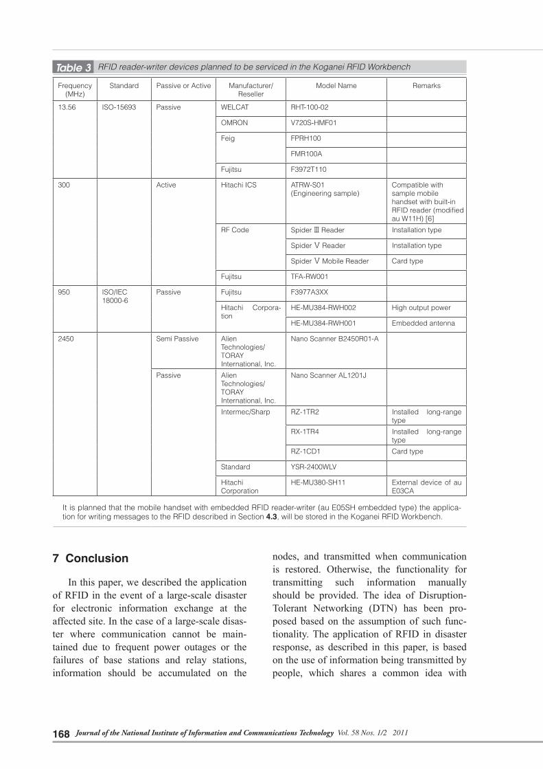
disclose all of our research and development results, including the applications described in this paper, together with the RFID reader-writ-ers and associated devices, as part of the com-mon-use facility program that starts from FY2011. These results and applications will be provided for a fee to external research and development organizations. Figure 21 shows the facility. This facility is called the Koganei RFID Workbench and planned to be serviced widely with RFID reader-writers and associat-ed devices. The Koganei RFID Experimental Room [17], which was facilitated in FY2003 as one of the open laboratories, is equipped with these devices. Table 3 shows the list of RFID reader-writer devices that are expected to be serviced.
The Koganei RFID Experiment Room was used for exhibitions, such as Interlop. To assist in research and development for disaster pre-vention, experimental emergency exit lights have been installed. The laboratory was con-sidered for use for the Development of an Information System to Support Fire-Fighting Activities promoted by the Ministry of Inter-nal Affairs and Communications, the Fire and Disaster Management Agency [18].
Fig.21 Koganei RFID Workbench
Journal of the National Institute of Information and Communications Technology Vol. 58 Nos. 1/2 2011168
7 Conclusion
In this paper, we described the application of RFID in the event of a large-scale disaster for electronic information exchange at the affected site. In the case of a large-scale disas-ter where communication cannot be main-tained due to frequent power outages or the failures of base stations and relay stations, information should be accumulated on the
nodes, and transmitted when communication is restored. Otherwise, the functionality for transmitting such information manually should be provided. The idea of Disruption-Tolerant Networking (DTN) has been pro-posed based on the assumption of such func-tionality. The application of RFID in disaster response, as described in this paper, is based on the use of information being transmitted by people, which shares a common idea with
Frequency (MHz)
Standard Passive or Active Manufacturer/Reseller
Model Name Remarks
13.56 ISO-15693 Passive WELCAT RHT-100-02
OMRON V720S-HMF01
Feig FPRH100
FMR100A
Fujitsu F3972T110
300 Active Hitachi ICS ATRW-S01(Engineering sample)
Compatible with sample mobile handset with built-in RFID reader (modified au W11H) [6]
RF Code Spider Ⅲ Reader Installation type
Spider Ⅴ Reader Installation type
Spider Ⅴ Mobile Reader Card type
Fujitsu TFA-RW001
950 ISO/IEC18000-6
Passive Fujitsu F3977A3XX
Hitachi Corpora-tion
HE-MU384-RWH002 High output power
HE-MU384-RWH001 Embedded antenna
2450 Semi Passive AlienTechnologies/TORAY International, Inc.
Nano Scanner B2450R01-A
Passive Alien Technologies/TORAY International, Inc.
Nano Scanner AL1201J
Intermec/Sharp RZ-1TR2 Installed long-range type
RX-1TR4 Installed long-range type
RZ-1CD1 Card type
Standard YSR-2400WLV
Hitachi Corporation
HE-MU380-SH11 External device of au E03CA
� It is planned that the mobile handset with embedded RFID reader-writer (au E05SH embedded type) the applica-tion for writing messages to the RFID described in Section 4.3, will be stored in the Koganei RFID Workbench.
Table 3 RFID reader-writer devices planned to be serviced in the Koganei RFID Workbench

169TAKIZAWA Osamu et al.
DTN. However, our application is limited to information exchange mediated by the RFID reader-writer, and thus the RFID is not used to accumulate information received from the net-work. Therefore, it is desirable that a new device enables the accumulation of informa-tion delivered by a network in normal times, and if the network fails, the accumulated information is retrieved using the RFID reader by way of non-contact reading.
A passive RFID, which does not require a power source for any operation, such as enter-ing information, accumulating data, or output-ting data, is disaster-resilient and inexpensive memory device that requires no maintenance and that can be used semi-permanently. In the future, if an RFID is buried anywhere in an urban landscape, including under wall tiles, it can be used as a reference point for position-ing, and an invisible poster or message can be left anywhere. In this way, it can be used for various purposes either during normal times or in the event of a disaster.
Over the past ten years, we have been engaged in the application of RFIDs to disas-ter response. During this time, RFID technolo-gies have made dramatic advances. Incorpo-rating an RFID reader-writer into cell phones that are carried by a large population of users was essential in the progress to turn the RFID into an extensively used device, not limited to specific business purposes such as logistics. This progress was finally achieved this fiscal year through the project entitled Research and Development of Ubiquitous Platform Technol-ogy under the auspices of the Ministry of Internal Affairs and Communications. The application we developed is intended to be used by members of the public to store data, and preparations have just been completed to achieve this objective. Nevertheless, a number
of problems remain to be resolved before the technologies can be significantly distributed, and the RFID device itself should evolve. It is necessary to achieve, for example, faster read-write processing of RFID data and larger data storage.
Acknowledgments
Part of the RFID positioning was devel-oped by RFID-based Positioning Systems for Enhancing Safety and Sense of Security (prin-cipal researcher: Kaoru Sezaki) (FY2006 –FY2008). Part of feature for the terminal to access the location resolution server was developed by Scientific Research B of Grants-in-Aid for Scientific Research (project number 17310101), Research of Disaster Information Collection and Sharing System using RFID and GIS (principal researcher: Osamu Takiza-wa) (FY2005 – FY2008). The hybrid RFID system as a base of terminal hardware was developed by the Special Project for Earth-quake Disaster Mitigation in Urban Areas, of the Ministry of Education, Culture, Sports, Science and Technology, Development of Advanced Robots and Information Systems for Disaster Response (principal research: Satoshi Tadokoro) (FY2002 – FY2006). Part of application base for GIS for damage inves-tigation was developed by the Special Coordi-nation Funds for the promotion of science and technology, Disaster Mitigation Using Tech-nology of Information Sharing for Risk Man-agement (principal researcher: Tsuneo Kataya-ma) (FY2004 – FY2006). Presenting the speech system at various exhibitions by NICT Incubations was assisted by the Support Cen-ter for Advanced Telecommunications Tech-nology Research.
References 1 Osau Takizawa, Akihiro Shibayama, Masafumi Hosokawa, and Yoshiaki Hisada, “Research into the
Disaster Information Collection Support System,” Journal of the National Institute of Information and
Communications Technology, Vol. 51, Nos. 1/2, pp. 247–263, 2005.

Journal of the National Institute of Information and Communications Technology Vol. 58 Nos. 1/2 2011170
2 O. Takizawa, A. Shibayama, M. Hosokawa, K. Takanashi, M. Murakami, Y. Hisada, Y. Hada, K. Kawaba-
ta, I. Noda, and H. Asama, “Hybrid Radio Frequency Identification System for Use in Disaster Relief as
Positioning Source and Emergency Message Boards,” Mobile Response 2007, Lecture Notes in Com-
puter Science, LNCS 4458, pp. 85–94, Springer, 2007.
3 Osamu Takizawa, “Implementation and Demonstration Experiment of RFID for Disaster Response,” 2008
RFID Technology Outlook, pp. 1–177, Electronic Journal, Inc., 2007.
4 Osamu Takizawa, “Research of Disaster Information Collection and Sharing System using RFID and
GIS,” 2008 annual report of the Grants-in-Aid for Scientific Research, http://kaken.nii.ac.jp/
ja/p/17310101/2008/8/ja, 2009.
5 Osamu Takizawa, Akihiro Shibayama, Masafumi Hosokawa, Masahiro Murakami, and Yoshiaki Hisada,
“Development of Disaster Information Sharing System Using Hybrid Wireless Tags,” the Conference of
System Integration Division, the Society of Instrument and Control Engineers, 2006.
6 KDDI Corporation, “Development of Cellular Phone Equipped with Electronic Tag Reader,” KDDI News
Release, No. 2005-047, 2005.
7 Shinzo Ohkubo and Kosei Takiishi, “Decreasing Power Consumption of Active RFID Reader,” NTT
DoCoMo Technical Journal, Vol. 14, No. 1, pp. 32–38, 2006.
8 Yoshifumi Shimazaki, “Mu-Chip Reader Gathering Attention as a Mobile Solution,” TIME & SPACE, April
and May issue, pp. 16–17, KDDI Corporation, 2008.
9 Ministry of Internal Affairs and Communications, “Research and Development on Ubiquitous Platform
Technology (Ubiquitous Terminal Technology) Basic Study Plan, ” http://www.soumu.go.jp/s-news/2008/
pdf/080327_1_bs3.pdf, 2008.
10 “Hitachi and KDDI jointly develop ubiquitous terminal technology mounting UHF band RFID reader-writ-
er on cell phones, as the result of “Research and Development of Ubiquitous Terminal Technology” proj-
ect by the Ministry of Internal Affairs and Communication,” Hitachi Corporation/KDDI Corporation News
Release, July 12th, 2010.
11 O. Takizawa, M. Hosokawa, K. Takanashi, Y. Hada, A. Shibayama, and B. Jeong, “Three-Way Pinpoint-
ing of Emergency Calls from Cell Phones Equipped with RFID Readers,” Mobile Response 2008, Lec-
ture Notes in Computer Science, LNCS 5424, pp. 66–75, Springer, 2009.
12 Masafumi Hosokawa, Kenichi Takanashi, and Osamu Takizawa, “Emergency Call System by Cell
Phones equipped with RFID Positioning,” Theory and Applications of GIS (journal of the GIS Association
of Japan), Vol. 18, No. 1, pp. 79–85, 2010.
13 Osamu Takizawa, Masafumi Hosokawa, Yoshifumi Shimazaki, and Hiroyuki Fukuoka, “Development of
Electronic Poster and Message Board with Location Information of Cell Phone Using Bluetooth and
RFID,” Transactions of Information Processing Society of Japan, Vol. 51, No. 1, pp. 174–179, 2010.
14 Osamu Takizawa, “Positioning with RFID for Greater Safety,” Monthly Magazine of Automatic Recogni-
tion, Special issue of August 2009, pp. 30–34, Japan Industrial Publishing Co., Ltd., 2009.
15 Osamu Takizawa, Masafumi Hosokawa, and Akihiro Shibayama, “Development of GIS Terminal for
Disaster Survey Applicable to Multi RFIDs for Positioning,” Theory and Applications of GIS (Journal of
the GIS Association of Japan), Vol. 18, No. 1, pp. 87–93, 2010.
16 “Outcomes and future issues of science and technologies group — result of follow-up of science and
technologies group which completed supplementary project in FY 2008 (Plan),” Document of Council
for Science and Technology Policy, Research Committee of Basic Policy Promotion, 1-1, pp. 48–60,
http://www8.cao.go.jp/cstp/tyousakai/suisin/haihu13/siryo1-1-4.pdf, May 27, 2009.

171TAKIZAWA Osamu et al.
17 “Building the most advanced open test bed — enhancement of Keihainna Open Laboratory, establish-
ment of verification facility for electronic tag, and commencement of JGNII operation —,” Press release
of the National Institute of Information and Communications Technology, http://www2.nict.go.jp/pub/
whatsnew/press/h16/040512/040512.html, May 12, 2004.
18 Meeting to discuss the development of fire fighting activity support information system in a space where
fire fighting is difficult, “Development report of fire fighting support information system in a space where
fire fighting is difficult,” pp. 73–74, http://www.fdma.go.jp/html/new/pdf/040521_hokoku.pdf, Ministry of
Internal Affairs and Communications, Fire and Disaster Management Agency, March 2004.
19 Akihiro Shibayama, Osamu Takizawa, Masafumi Hosokawa, Tsuguyuki Ichii, Yoshiaki Hisada and Masa-
hiro Murakami, “A Study on the Information System Using Radio Frequency Identification,” Proceedings
of the annual conference of the Institute of Social Safety Science, No. 8, pp. 135–144, 2006.
20 Akihiro Shibayama, Makoto Endo, Osamu Takizawa, Masafumi Hosokawa, Tsuguyuki Ichii, Yoshiaki
Hisada, Shinsaku Zama, and Masahiro Murakami, “Development of Support System for Disaster Infor-
mation Collection,” Proceedings of the Architectural Institute of Japan, No. 23, pp. 497–502, 2006.
21 O. Takizawa, “RFID-based Disaster-relief System,” Sustainable Radio Frequency Identification Solutions,
pp. 241–266, Intech (ISBN 978-953-7619-74-9), 2010.
(Accepted March 30, 2011)
† Currently, Manager, Technology Transfer Promotion Office, Outcome Promotion Department
TAKIZAWA Osamu, Ph.D.†
Group Leader, Disaster Management and Mitigation Group (April 2006 – March 2011) / Group Leader, Security Fundamentals Group (May 2008 – March 2010), Information Security Research Center
Telecommunication for Disaster Management, Application Security
HOSOKAWA Masafumi, Ph.D.
Head, Earthquake and Natural Disas-ter Laboratory, National Research Institute of Fire and Disaster, Fire and Disaster Management Agency/Guest Researcher, Disaster Management and Mitigation Group, Information Security Research Center (Sept. 2008 – March 2011)
Fire and Disaster Management
SHIBAYAMA Akihiro, Ph.D.
Assistant Professor, Disaster Control Research Center, Tohoku University Former: Expert Researcher, Disaster Management and Mitigation Group, Information Security Research Center (April 2007 – Nov. 2008)
Disaster Prevention of Buildings
