(3) (total 5 marks) - pmt
TRANSCRIPT

Q1. A heat pump is used for heating a small workshop. The heat pump extracts energy from a patch of ground outside the workshop. The coefficient of performance of the heat pump is 3.2 and the average electrical power input is 780 W.
(a) (i) Calculate the rate at which energy is delivered to the workshop.
answer = ...................................... W (1)
(ii) Calculate the rate at which energy is extracted from the ground.
answer = ...................................... W (1)
(b) A student claims: "A heat pump delivers more energy than is supplied to it". Discuss this statement and explain why a heat pump does not contradict the law of conservation of energy or the second law of thermodynamics.
.....................................................................................................................
.....................................................................................................................
.....................................................................................................................
.....................................................................................................................
.....................................................................................................................
.....................................................................................................................
..................................................................................................................... (3)
(Total 5 marks)
PhysicsAndMathsTutor.com 1

Q2. (a) The coefficient of performance of a refrigerator is given by
With reference to a refrigerator, explain the terms Qin and Q
out.
......................................................................................................................
......................................................................................................................
......................................................................................................................
...................................................................................................................... (2)
(b) A refrigerator is designed to make ice at –10 °C from water initially at room temperature. The energy needed to make 1.0 kg of ice at –10 °C from water initially at room temperature is 420 kJ. The refrigerator has a coefficient of performance of 4.5.
(i) Calculate the power input to the refrigerator if it is required to make 5.5 kg of ice every hour.
answer = ...................................... W (2)
(ii) Calculate the rate at which energy is delivered to the surroundings of the refrigerator.
answer = ...................................... W (1)
(Total 5 marks)
PhysicsAndMathsTutor.com 2
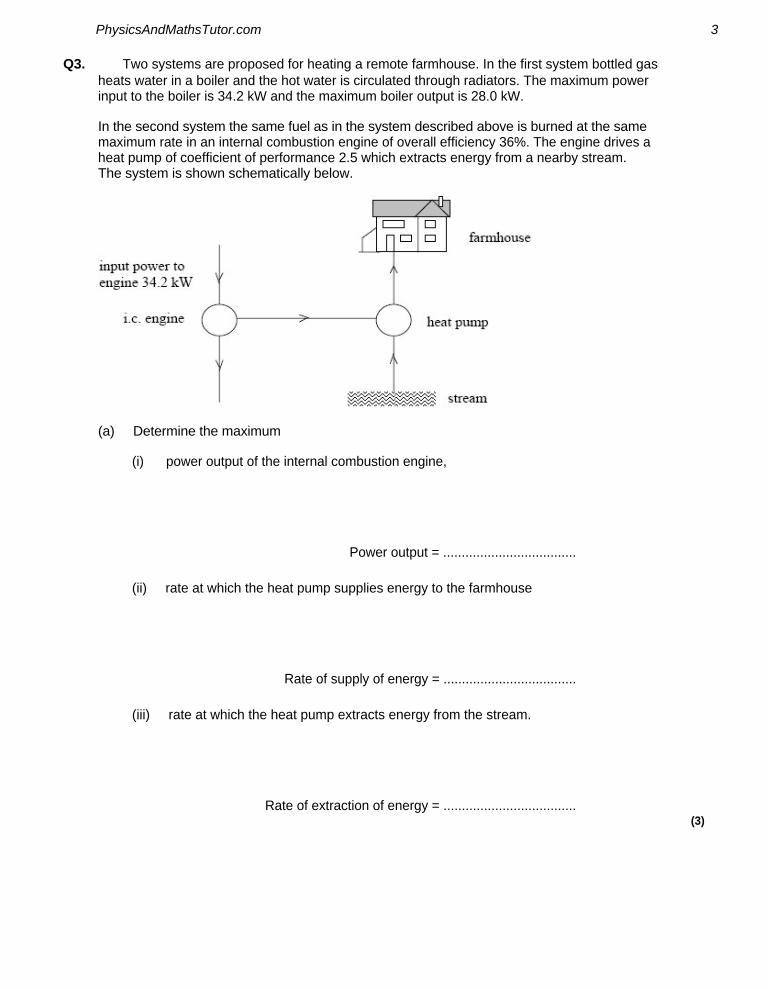
Q3. Two systems are proposed for heating a remote farmhouse. In the first system bottled gas heats water in a boiler and the hot water is circulated through radiators. The maximum power input to the boiler is 34.2 kW and the maximum boiler output is 28.0 kW.
In the second system the same fuel as in the system described above is burned at the same maximum rate in an internal combustion engine of overall efficiency 36%. The engine drives a heat pump of coefficient of performance 2.5 which extracts energy from a nearby stream. The system is shown schematically below.
(a) Determine the maximum
(i) power output of the internal combustion engine,
Power output = ....................................
(ii) rate at which the heat pump supplies energy to the farmhouse
Rate of supply of energy = ....................................
(iii) rate at which the heat pump extracts energy from the stream.
Rate of extraction of energy = .................................... (3)
PhysicsAndMathsTutor.com 3

(b) State which system is cheaper to run, giving two reasons for your answer.
......................................................................................................................
......................................................................................................................
......................................................................................................................
......................................................................................................................
...................................................................................................................... (3)
(Total 6 marks)
Q4. The figure below shows a model rocket for demonstrating the principle of rocket propulsion. Air is pumped into an upside-down plastic bottle that has been partly filled with water.
When the pressure reaches 3.6 × 10⁵ Pa, (i.e. 2.6 × 10⁵ Pa above atmospheric pressure) the air valve is forced out by the water pressure and the air in the bottle expands. The expanding air force the water out of the neck of the bottle at high peed; thi provide the thru t that lift the bottle high into the air.
PhysicsAndMathsTutor.com 4

The graph shows the variation of pressure with volume for the air initially in the bottle as it expands from 3.6 × 10⁵ Pa to atmospheric pressure, assuming the expansion is adiabatic.
(a) Use the graph to estimate the work done by the air as it expands from a pressure of
3.6 × 10⁵ Pa to atmospheric pressure.
answer = ...................................... J (3)
PhysicsAndMathsTutor.com 5

(b) With reference to the graph above, state and explain whether the rocket would have reached the same height if the air had expanded isothermally.
......................................................................................................................
......................................................................................................................
......................................................................................................................
......................................................................................................................
......................................................................................................................
...................................................................................................................... (3)
(Total 6 marks)
Q5. An inventor has designed a gas engine for a small combined heat and power plant which will operate between temperatures of 1400 K and 360 K. The inventor makes two claims about the performance of the engine:
claim 1 When the engine consumes gas of calorific value 36 MJ kg–1 at a rate of 9.6 kg h–1, it will deliver a useful mechanical output power of 80 kW.
claim 2 At the same time, the engine will also provide energy at the rate of at least 20 kW for heating purposes.
(a) Show that the input power to the engine is approximately 100 kW.
......................................................................................................................
...................................................................................................................... (2)
(b) Calculate the maximum possible efficiency of any heat engine which operates between temperatures of 1400 K and 360 K.
......................................................................................................................
......................................................................................................................
...................................................................................................................... (1)
PhysicsAndMathsTutor.com 6

(c) Using the result of your calculation in part (b) and any other necessary calculations, explain whether either or both of the inventor’s claims are justified. You may be awarded marks for the quality of written communication in your answer.
......................................................................................................................
......................................................................................................................
......................................................................................................................
......................................................................................................................
......................................................................................................................
...................................................................................................................... (4)
(Total 7 marks)
Q6. Figure 1 shows a model steam engine used in a school to demonstrate energy transfers. The steam engine drives a dynamo which requires a constant torque. By means of valves, high pressure steam is applied to one side of the piston on the outward stroke (as shown) and to the other side of the piston on the inward stroke. The motion of the piston is converted to rotary motion by a connecting rod and crank. A flywheel (not shown) is fitted to the crankshaft.
Figure 1
PhysicsAndMathsTutor.com 7

Figure 2 shows how the torque on the crankshaft due to the engine varies with the crankshaft angle θ for one rotation of the crankshaft. The broken line shows the constant dynamo torque required from the output.
Figure 2
(a) State and explain how you could use Figure 2 to determine the work done by the engine in one revolution of the crankshaft.
........................................................................................................................
........................................................................................................................
........................................................................................................................
........................................................................................................................ (1)
(b) The dynamo has a low moment of inertia.
• Explain why the engine torque varies over a cycle.
• Explain why, in terms of kinetic energy or angular momentum, it is necessary to fit a flywheel to the crankshaft of the engine.
• Discuss how the motion of the crankshaft is influenced by the value of the moment of inertia of the flywheel.
PhysicsAndMathsTutor.com 8
The quality of your written communication will be assessed in your answer.
........................................................................................................................
........................................................................................................................
........................................................................................................................
........................................................................................................................
........................................................................................................................
........................................................................................................................
........................................................................................................................
........................................................................................................................
........................................................................................................................
........................................................................................................................
........................................................................................................................
........................................................................................................................
........................................................................................................................ (6)
(Total 7 marks)
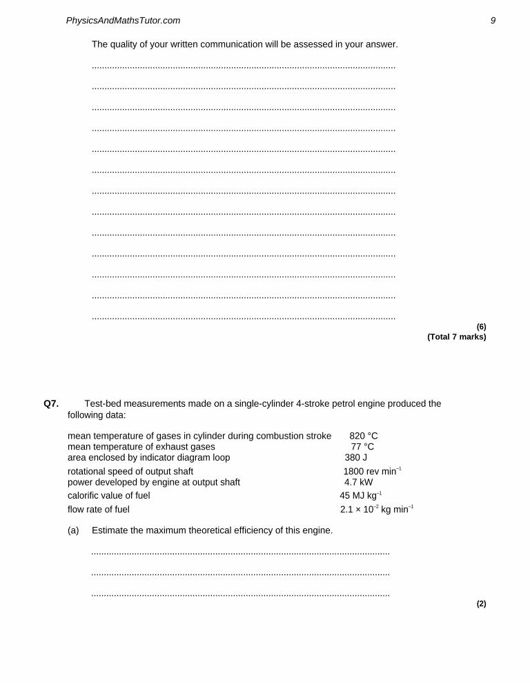
Q7. Test-bed measurements made on a single-cylinder 4-stroke petrol engine produced the following data:
mean temperature of gases in cylinder during combustion stroke 820 °C mean temperature of exhaust gases 77 °C area enclosed by indicator diagram loop 380 J
rotational speed of output shaft 1800 rev min–1
power developed by engine at output shaft 4.7 kW calorific value of fuel 45 MJ kg–1
flow rate of fuel 2.1 × 10⁻² kg min–1
(a) Estimate the maximum theoretical efficiency of this engine.
......................................................................................................................
......................................................................................................................
...................................................................................................................... (2)
PhysicsAndMathsTutor.com 9

(b) Calculate the indicated power of the engine.
......................................................................................................................
......................................................................................................................
...................................................................................................................... (2)
(c) Calculate the power dissipated in overcoming the frictional losses in the engine.
......................................................................................................................
...................................................................................................................... (1)
(d) Calculate the rate at which energy is supplied to the engine.
......................................................................................................................
......................................................................................................................
...................................................................................................................... (1)
(e) Calculate the overall efficiency of the engine.
......................................................................................................................
......................................................................................................................
...................................................................................................................... (1)
(Total 7 marks)
PhysicsAndMathsTutor.com 10

Q8. The line ABCD in the graph below is the indicator diagram for a single cylinder steam engine in which the exhaust steam is released directly into the atmosphere.
(a) (i) Calculate the work done by the engine during the cycle ABCD.
.............................................................................................................
.............................................................................................................
.............................................................................................................
.............................................................................................................
.............................................................................................................
(ii) Calculate the indicated output power of the engine when running at 3 cycles per second.
.............................................................................................................
.............................................................................................................
(iii) To achieve this output power, fuel of calorific value 34 MJ kg–1 must be burnt at a
rate of 2.4 × 10⁻² kg s–1. Calculate the thermal efficiency of the engine.
.............................................................................................................
.............................................................................................................
.............................................................................................................
............................................................................................................. (5)
PhysicsAndMathsTutor.com 11

(b) The line ABED in the graph is the indicator diagram for the same engine after a modification has been made so that the exhaust steam is passed into a condenser, where it is converted to water. The hot water formed is returned to the boiler for reheating.
Without further calculation, compare the performance of the modified engine with that of the original engine when both engines are making the same number of cycles per second. In your comparison you should consider the fuel consumption of the engines, the mass of steam supplied to them, their power outputs and efficiencies.
You may be awarded marks for the quality of written communication in your answer.
......................................................................................................................
......................................................................................................................
......................................................................................................................
......................................................................................................................
......................................................................................................................
......................................................................................................................
...................................................................................................................... (3)
(Total 8 marks)
Q9. (a) Figure 3 shows the indicator diagram for a theoretical or ideal four-stroke petrol engine (Otto) cycle.
Figure 1
PhysicsAndMathsTutor.com 12

Use Figure 1 to describe the process that occurs during each of the parts A to B, B to C, C to D and D to A of the cycle. Describe whether heating or cooling is taking place, the type of process and whether work is being done on or by the air.
The quality of your written answer will be assessed in this question.
......................................................................................................................
......................................................................................................................
......................................................................................................................
......................................................................................................................
......................................................................................................................
......................................................................................................................
......................................................................................................................
......................................................................................................................
......................................................................................................................
......................................................................................................................
......................................................................................................................
......................................................................................................................
......................................................................................................................
......................................................................................................................
......................................................................................................................
...................................................................................................................... (6)
PhysicsAndMathsTutor.com 13

(b) Show, on Figure 2, how the indicator diagram might be expected to appear if measurements of pressure and volume were made on a real four-stroke petrol engine of the same volume under operating conditions. The ideal cycle is shown in dashed lines as a guide.
Figure 2
(2)
(Total 8 marks)
Q10. (a) The first law of thermodynamics can be represented by ΔQ = ΔU + ΔW.
State and explain, with reference to the equation, two ways in which the internal energy of a gas can be decreased.
You may be awarded marks for the quality of written communication in your answer.
......................................................................................................................
......................................................................................................................
......................................................................................................................
......................................................................................................................
......................................................................................................................
......................................................................................................................
...................................................................................................................... (3)
(b) A volume of 20 m3 of exhaust gas from a diesel engine leaves the exhaust pipe at a
pressure of 1.0 × 10⁵ Pa. The gas is cooled by the surrounding atmosphere, which is also at a pressure of 1.0 × 10⁵ Pa, and, as a result, the exhaust gas contracts to half its volume.
(i) Calculate the work done by the atmosphere on the gas during this contraction.
.............................................................................................................
PhysicsAndMathsTutor.com 14

(ii) 4.9 MJ of heat is transferred to the atmosphere during cooling. Using the first law of thermodynamics, calculate the change in internal energy of the gas.
.............................................................................................................
.............................................................................................................
.............................................................................................................
(iii) Use the axes below to represent this process as a p-V diagram, showing the direction of the process.
(5)
(Total 8 marks)
PhysicsAndMathsTutor.com 15

Q11. A small, two-cylinder pump shown in the diagram is used for aerating water in an aquarium. The two cylinders are identical and each has a piston driven by a rotating driveshaft so that both cylinders pump air to the aquarium during one rotation of the driveshaft. The inlet and outlet valves controlling the airflow are not shown.
Air at a pressure of 1.00 × 10⁵ Pa is drawn into the cylinders, is compressed and exhausted to an underwater outlet in the aquarium, where it is released as a stream of bubbles. The graph shows the p-V diagram for one cycle of one cylinder.
(a) Use the graph to determine the outlet pressure of the air from the pump.
...................................................................................................................... (1)
PhysicsAndMathsTutor.com 16
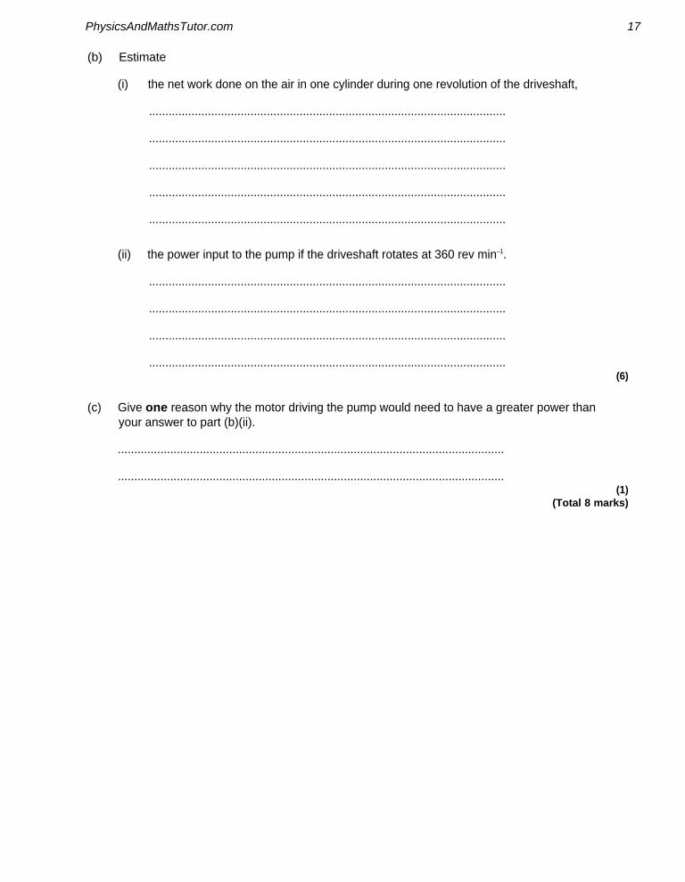
(b) Estimate
(i) the net work done on the air in one cylinder during one revolution of the driveshaft,
.............................................................................................................
.............................................................................................................
.............................................................................................................
.............................................................................................................
.............................................................................................................
(ii) the power input to the pump if the driveshaft rotates at 360 rev min–1.
.............................................................................................................
.............................................................................................................
.............................................................................................................
............................................................................................................. (6)
(c) Give one reason why the motor driving the pump would need to have a greater power than your answer to part (b)(ii).
......................................................................................................................
...................................................................................................................... (1)
(Total 8 marks)
PhysicsAndMathsTutor.com 17

Q12. The line ABCD in the graph below is the indicator diagram for a single cylinder steam engine in which the exhaust steam is released directly into the atmosphere.
(a) (i) Calculate the work done by the engine during the cycle ABCD.
Work done = ....................................
(ii) Calculate the indicated output power of the engine when running at 3 cycles per second.
Indicated output power = ....................................
(iii) To achieve this output power, fuel of calorific value 34 MJ kg–1 must be burnt at a rate of 2.4 × 10⁻² kg s–1. Calculate the thermal efficiency of the engine.
Thermal efficiency = .................................... (6)
PhysicsAndMathsTutor.com 18

(b) The line ABED in the graph is the indicator diagram for the same engine after a modification has been made so that the exhaust steam is passed into a condenser, where it is converted to water. The hot water formed is returned to the boiler for reheating.
Without further calculation, compare the performance of the modified engine with that of the original engine when both engines are making the same number of cycles per second. In your comparison you should consider the fuel consumption of the engines, the mass of steam supplied to them, their power outputs and efficiencies.
......................................................................................................................
......................................................................................................................
......................................................................................................................
......................................................................................................................
......................................................................................................................
......................................................................................................................
...................................................................................................................... (3)
(Total 9 marks)
PhysicsAndMathsTutor.com 19
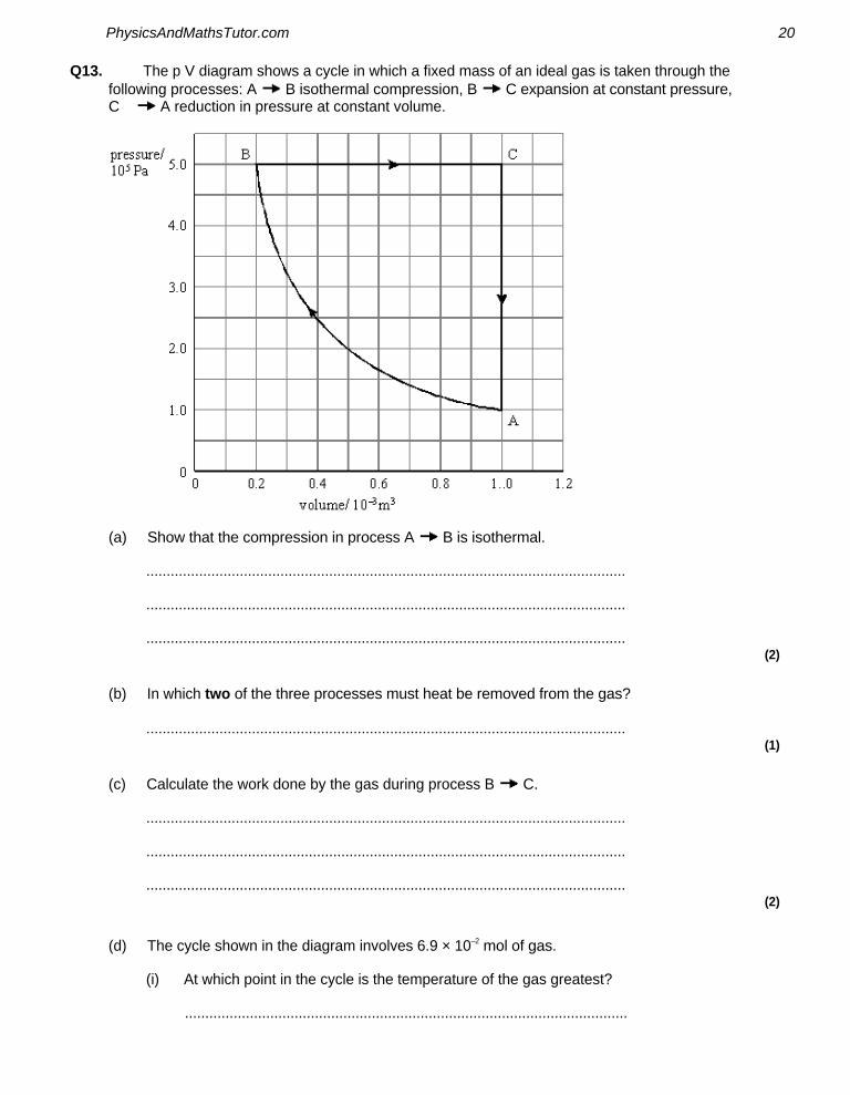
Q13. The p V diagram shows a cycle in which a fixed mass of an ideal gas is taken through the following processes: A B isothermal compression, B C expansion at constant pressure, C A reduction in pressure at constant volume.
(a) Show that the compression in process A B is isothermal.
......................................................................................................................
......................................................................................................................
...................................................................................................................... (2)
(b) In which two of the three processes must heat be removed from the gas?
...................................................................................................................... (1)
(c) Calculate the work done by the gas during process B C.
......................................................................................................................
......................................................................................................................
...................................................................................................................... (2)
(d) The cycle shown in the diagram involves 6.9 × 10⁻² mol of gas.
(i) At which point in the cycle is the temperature of the gas greatest?
.............................................................................................................
PhysicsAndMathsTutor.com 20

(ii) Calculate the temperature of the gas at this point.
.............................................................................................................
.............................................................................................................
.............................................................................................................
............................................................................................................. (4)
(Total 9 marks)
Q14. A four-stroke diesel engine with four cylinders is running at constant speed on a test bed. An indicator diagram for one cylinder is shown in the figure below and other test data are given below:
measured output power of engine (brake power) = 55.0 kW fuel used in 100 seconds = 0.376 litre calorific value of fuel = 38.6 MJ litre–1
engine speed = 4100 rev min–1
PhysicsAndMathsTutor.com 21

(a) (i) Determine the indicated power of the engine, assuming all cylinders give the same power.
answer = .................................... kW (4)
(ii) Calculate the overall efficiency of the engine.
answer = ........................................... (3)
(b) Account for the difference between the indicated power and brake power.
........................................................................................................................
........................................................................................................................
........................................................................................................................ (1)
(c) What is represented by the line AB on the figure above?
........................................................................................................................
........................................................................................................................ (1)
(Total 9 marks)
Q15. In an ideal ‘hot air’ engine, a fixed mass of air is continuously taken through the following four processes:
A → B isothermal compression at a temperature of 300 K. The work done on the air is 104 J.
B → C heating at constant volume.
C → D isothermal expansion. The work done by the expanding air is 173 J.
D → A cooling at constant volume.
PhysicsAndMathsTutor.com 22

The cycle is shown in the figure below.
(a) (i) Show that the temperature of the air at point D is 500 K.
(2)
(ii) Apply the first law of thermodynamics to calculate the energy supplied by heat transfer in process C → D.
answer = ........................................ J (2)
(b) The engine contains a device called a regenerator which stores all the energy rejected by cooling in process D → A and gives up all this energy to the air again in process B → C. This means that energy must be supplied to the air by heat transfer from an external source only in process C → D.
(i) Calculate the net work done during the cycle.
answer = ........................................ J (1)
PhysicsAndMathsTutor.com 23

(ii) Show that the efficiency of the cycle is the same as the maximum possible efficiency of any heat engine operating between the same highest and lowest temperatures in the cycle.
(2)
(c) On the axes below, sketch the cycle on a graph of volume V against temperature T. Label the points A, B, C and D.
(2)
(d) Several inventors have tried to build an engine that works on this cycle. Give two reasons why they have been unsuccessful.
.....................................................................................................................
.....................................................................................................................
.....................................................................................................................
.....................................................................................................................
..................................................................................................................... (2)
(Total 11 marks)
PhysicsAndMathsTutor.com 24

M1. (a) (i) 3.2 × 780 = 2500 W 1
(ii) 2500 – Qout
= 780
Qout
= 1720 W
or 3.2 =
giving Qout
= 1720 W
1
(b) • heat pump does deliver more energy than is input as work on the system but there must also be energy input from cold space
• obeys conservation of energy because work done plus energy from cold space (or equivalent, eg ground) equals energy by heat transfer to hot space (or equivalent)
• obeys second law because (reversed heat engine) operates between hot and cold spaces
[accept ‘source’ and ‘sink’]
• work done on the system requires energy transfer (from a heat engine elsewhere) so overall result is spreading out of energy [owtte]
max 3 [5]
M2. (a) (refrigerator operates between a cold space and a hot space)
Qout
is the energy removed from the fridge contents (or from the cold
space) (1)
Qin is the energy given to the surroundings (or to outside the fridge/hot
space) (1) 2
PhysicsAndMathsTutor.com 25

(b) (i) power for cooling ice = 5.5 × (420 × 103)/3600 = 642 W (1)
Pin = 642/4.5 = 142 W (1)
or energy taken from ice in 1 hour = 5.5 × 420 × 103 = 2310 kJ
Win = 2310/4.5 = 513 kJ (1)
Pin = = 142 W (1)
2
(ii) Q per s = 142 + 642
= 784 W (give CE) (1)
or Qin = Q
out + W
in = 513 kJ + 2310 kJ = 2820 kJ
Qin per s = = 784 W (1)
1 [5]
M3. (a) (i) Pout
= 0.36 × 34.2 = 12.3 kW (1)
(ii) Pfarm
= 12.3 × 2.5 = 30.8 kW (1)
(iii) Pstream
= 30.8 – 12.3 = 18.5 kW (1)
3
(b) two reasons in support of either choice
heat pump (1)
both systems use the same fuel so cost of same amount of fuel is same (1)
heat pump uses less fuel for the same output (1)
(or gives greater output for same amount of fuel (1))
can also use energy rejected from engine for heating (1) max 3
[6]
PhysicsAndMathsTutor.com 26

M4. (a) work done = area under line (1)
appropriate method for finding area eg counting squares (1)
correct scaling factor used (to give answer of 150 J ± 10 J) (1)
if candidate correctly calculates area under curve to a pressure of zero Pa, (330 J ± 20 J) award 2 marks
3
(b) if isothermal line would have been less steep (1)
(so greater area under line and) more work done (1)
so rocket would rise higher (1) 3
[6]
M5. (a) Pin(= calorific value × fuel flow rate)
= (1) (1) (for conversion to 3600 s) (= 96 kW) 2
(b) = 0.74 or 74% (1) 1
PhysicsAndMathsTutor.com 27

(c) η claimed in (a) = = 0.80 or 80% (1)
[or = 0.83 or 83%]
which is > 74%, so claim 1 is unjustified (1)
heat rejected from engine = Pin – P
out (1)
real mechanical Pout
must be < 0.74 × 100 i.e. < 74 kW (1)
so claim 2 is justified as Pin – P
out > 20 kW (1)
[alternative for (c):
maximum Pout = 71 kW (0.74 × 96) or 74 kW (0.74 × 100) (1)
which is < 80 kW, so claim 1 is unjustified (1)
heat rejected from engine is 25 kW (96 – 71) or 26 kW (100 – 74) (1)
actual wasted power must be > 25 kW (1)
claim 2 is justified as 25 kW > 20 kW (1)] Max 4
QWC 1 [7]
M6. (a) Either W = area under (engine torque) graph from 0 to 2π rad
OR W = area under graph because W = Tϴ
OR W = dynamo torque × 2π
OR W = area under dotted line / dynamo torque because W = Tϴ 1
(b) The candidate’s writing should be legible and the spelling, punctuation and grammar should be sufficiently accurate for the meaning to be clear.
The candidate’s answer will be assessed holistically. The answer will be assigned to one of three levels according to the following criteria.
PhysicsAndMathsTutor.com 28

High Level (Good to excellent): 5 or 6 marks
The information conveyed by the answer is clearly organised, logical and coherent, using appropriate specialist vocabulary correctly. The form and style of writing is appropriate to answer the question.
The candidate is aware that at two points in the cycle the engine torque is zero and can give a reason, perhaps mentioning moments or variation in steam pressure
The candidate identifies the flywheel as a store of rotational kinetic energy and can relate the energy changes in one cycle to the varying torque and clearly relates the fluctuation in speed to the value of the M of I of the flywheel.
Alternatively, the candidate states that the flywheel tends to maintain angular momentum and so takes the crank over the dead centres. The changing torque has the effect of changing the angular momentum (I∆ω) but if I is large, ∆ω is small. The candidate may go on to discuss effect of I being very large (e.g long acceleration time from start).
Intermediate Level (Modest to adequate): 3 or 4 marks
The information conveyed by the answer may be less well organised and not fully coherent. There is less use of specialist vocabulary, or specialist vocabulary may be used incorrectly. The form and style of writing is less appropriate. The candidate correctly identifies that a flywheel will make for smoother motion and may show an understanding that a flywheel acts as an energy reservoir, but may not be able to link the motion of the flywheel to the engine torque graph. Candidates answering in terms of angular momentum appreciate that the flywheel’s angular momentum will take it over the dead centres The candidate identifies that an increase in moment of inertia gives smoother running/less variation in speed per cycle. Reasons for the variation in torque may not refer to moments but candidate may state that torque is zero when crank and con rod are in line.
Low Level (Poor to limited): 1 or 2 marks
The information conveyed by the answer is poorly organised and may not be relevant or coherent. There is little correct use of specialist vocabulary. The form and style of writing may be only partly appropriate. The candidate may be able to give a reason why the motion is not smooth and can identify that a flywheel will make for smoother running. There may be some reference to the flywheel storing energy. They may confuse power or angular momentum with energy.
PhysicsAndMathsTutor.com 29

The explanation expected in a competent answer should include a coherent selection of the following points concerning the physical principles involved and their consequences in this case.
• without flywheel motion will be jerky/unsmooth/cause vibrations OR flywheel makes motion smoother/less fluctuation in speed
• flywheel needed to take crank over dead centres (wtte)
• because torque is zero at dead centres
• torque varies because pressure on piston varies
• because force is in line with c’shaft/ no moment of force about c’shaft
• flywheel stores rotational kinetic energy when engine torque > dynamo torque
• flywheel gives up energy when engine torque < dynamo torque
• flywheel’s ang. momentum takes it over dead centres
• the greater I, the less the fluctuation in speed over one cycle
• over one cycle, work done by engine = work needed by dynamo
• so average engine torque = average dynamo (load) torque
• torque = rate of change of ang. momentum – high I gives less change in ω. 6
[7]
M7. (a) TH = 273 + 820 = 1093 (K), T
C = 273 + 77 = 350 (K) (1)
efficiency = = 0.68 or 68% (1) 2
(b) rotational speed of output shaft = = 15 rev s–1 (1)
(work output each cycle = 380 J, 2 rev ≡ 1 cycle in a 4 stroke engine)
indicated power = 15 × 190 = 5.7 kW (1) 2
(c) power lost (= indicated power –actual power) = 5.7 – 4.7 = 1.0 kW (1) (allow C.E. for incorrect value from (b))
1
(d) energy supplied per sec (= fuel flow rate x calorific value)
= 16 kW (15.8 kW) (1) 1
PhysicsAndMathsTutor.com 30

(e) efficiency = = = 0.29 or 29 %
(allow C.E. for value from (d)) 1
[7]
M8. (a) (i) work done = area enclosed by curve ABCD = 20 kJ (± 2 kJ) (1) satisfactory method of finding the area (1)
(ii) power = 20 kJ per cycle × 3 cycles per sec = 60 kJ (± 6 kJ) (1)
(iii) input power = fuel flow rate × calorific value
= 2.4 × 10–3 × 34 × 106 = 820 kW (1) (816 kW)
efficiency = = ×100 = 7.3(5)% (1)
(use of input power = 820 gives 7.3%)
(allow C.E. for values of output power and input power) 5
(b) modified engine: same steam requirement (1) less fuel supplied because of recycled heat (1) greater work output per cycle (because loop larger) (1) same speed, therefore greater power output (1) greater efficiency as P
out greater, P
in less (1)
max 3 QWC 1
[8]
PhysicsAndMathsTutor.com 31

M9. (a) The candidate’s writing should be legible and the spelling, punctuation and grammar should be sufficiently accurate for the meaning to be clear.
The candidate’s answer will be assessed holistically. The answer will be assigned to one of three levels according to the following criteria.
High Level (Good to excellent): 5 or 6 marks
The information conveyed by the answer is clearly organised, logical and coherent, using appropriate specialist vocabulary correctly. The form and style of writing is appropriate to answer the question.
The candidate correctly identifies the two adiabatic and two constant volume processes described in their correct sequence and gives detailed consideration of where heating, cooling and work transfers take place. The candidate states that work is done on the gas only in A → B and by the gas only in C → D, and/or states that the area of the loop is net work done. There is also some reference to temperatures and pressures increasing or decreasing
Intermediate Level (Modest to adequate): 3 or 4 marks
The information conveyed by the answer may be less well organised and not fully coherent. There is less use of specialist vocabulary, or specialist vocabulary may be used incorrectly. The form and style of writing is less appropriate.
The candidate correctly identifies where some of the heat and work transfers take place but the answer is much more limited. The adiabatic processes may not be named as such, but there is a statement that work is done in these processes or that there is no heat transfer. One process might be missed out altogether or be incorrect. There may be reference to temperatures, volumes and pressures increasing or decreasing.
Low Level (Poor to limited): 1 or 2 marks
The information conveyed by the answer is poorly organised and may not be relevant or coherent. There is little correct use of specialist vocabulary. The form and style of writing may be only partly appropriate.
The candidate may refer (incorrectly) to the four processes as making up the four strokes of the engine real engine and some credit may be given if there is a statement that A → B is the compression stroke and C → D is the power stroke. The answer may be written mainly in terms of pressures, volumes and temperatures increasing or decreasing with little reference to the type of process or heat or work transfers. The candidate may relate the answer to a real engine rather than the theoretical cycle eg ‘the spark occurs at B’
PhysicsAndMathsTutor.com 32

The explanation expected in a competent answer should include a coherent selection of the following points concerning the physical principles involved and their consequences in this case.
A to B work done on air adiabatic compression no heat transfer (from air) temperature rises
B to C no work done heating at constant volume temperature rises (and also pressure)
C to D work done by air accept power stroke adiabatic expansion no heat transfer (to air) work done at expense of kinetic energy of molecules
D to A cooling (or heat rejected) at constant volume with no work done temperature falls
accept answers which cover above points and include reference to piston, cylinder, valves
max 6
(b)
induction and exhaust ‘pumping’ loop shown (1)
loop of smaller area than ideal loop with ‘rounded’ corners (1) 2
[8]
PhysicsAndMathsTutor.com 33

M10. (a) remove heat from the gas (1) correct reference to equation (e.g. ΔQ negative, W zero, then ΔU must be negative so U decreases) (1)
allow gas to do work (1) correct reference to equation (e.g. W positive, ΔQ zero, then ΔU must be negative so U decreases) (1)
max 3 QWC 1
(b) (i) W ( pdV) 1 0 × 105 × 10 1 0 × 106 J (1) (1 0 MJ)
(ii) –4.9 (MJ) = ΔU – 1 (MJ) (1) ΔU = (–)3.9 MJ (1)
(iii) graph to show: straight line between (20, 1.0) and (10, 1.0) (1) direction showing decreasing volume (1)
5 [8]
M11. (a) 1.3 × 10⁵ Pa (1)
1
(b) (i) work done = area enclosed by loop (1) suitable method used to find area (e.g. counting squares) (1) correct scaling factor used (1) (work done) = 0.11 J (1) (accept 0.08 to 0.14 J)
(ii) 360 rev min–1 = 6 cycles sec–1 (1)
power (= 2 cylinders × 0.11 J per cylinder × 6 cycles sec–1)
= 2 × 6 × 0.11 = 1.3 W (1) (0.96 to 1.56 W) 6
(c) friction between sliding surfaces air resistance in tubing heat generated by fast compression lost to surroundings (any one) (1)
1 [8]
PhysicsAndMathsTutor.com 34

M12. (a) (i) work done = area enclosed by curve ABCD = 20 kJ (± 2kJ)(1)
satisfactory method used to find area e.g. counting squares (1)
correct scaling factor used (e.g. 1 small square = 40 J) (1)
(ii) power = 20 kJ per cycle × 3 cycle per second = 60 kW (± 6 kW) (1)
(iii) input power (= fuel flow rate × calorific value)
= 2.4 × 10–2 × 34 × 106 = 816 kW (1)
efficiency = Pout
/Pin = × 100 = 0.07 or 7% (1)
6
(b) modified engine:
same mass of steam required
less fuel required because of recycled heat
greater work output per cycle because loop larger
same speed so greater power output
greater efficiency as Pout
is greater and Pin less
(1)(1)(1) any three 3
[9]
M13. (a) pV = constant for any two points online AB (1) two points chosen and constant calculated (1) (e.g. at A, pV = 1.0 × 105 × 1.0 × 10–3 = 100 (J)
at B, pV = 5.0 × 105 × 0.2 × 10–3 = 100 (J)) 2
(b) A → B and C → A (1) 1
(c) W = pΔV = 5.0 × 105 × (1.0 – 0.2) × 10–3 = 400 (J) (1)
1
PhysicsAndMathsTutor.com 35

(d) (i) C (1) 1
(ii) pV = nRT (1)
5.0 × 105 × 1.0 × 10–3 = 6.9 × 10–2 x 8.3 × T (1)
T=870K (872K) (1)
(allow C.E. if wrong point in (i)) 4
[9]
M14. (a) (i) Indicated work per cylinder = area of loop [either stated explicitly or shown on the Figure e.g. by shading or ticking squares or subsequent correct working.]
appropriate method for finding area e.g. counting squares
correct scaling factor used [to give answer of 470 J ± 50 J]
indicated power = 4 × 0.5 × (4100/60) × 470
= 64 kW 4
(ii) (Fuel flow rate = 0.376/100 = 0.00376 litre s−1 )
Input power (= c.v. × fuel flow rate)
= 38.6 × 106 × 0.00376
(= 145 kW)
Ƞ overall
= brake power/input power seen or implied from correct
ub equent working
= 55.0/145 = 0.38 or 38% 3
(b) Power expended in overcoming friction
in (all) the bearings / between piston & cylinder
and / or in circulating oil / cooling water
and / or driving auxiliaries (e.g. fuel injection pump) 1
(c) Represents the induction and exhaust (strokes) (which take place at nearly atmospheric pressure).
1 [9]
PhysicsAndMathsTutor.com 36

M15. (a) (i) use of PV/T = constant
= = 500 K 2
(ii) Q = ΔU + W
ΔU = 0
Q = W = 173 J 2
(b) (i) work out = 173 – 104 = 69 J 1
(ii) efficiency = 69/173 = 0.40 or 40%
ηmax
= (TH – T
C)/T
H
= (500 – 300)/500
= 0.39 or 40% 2
(c)
rectangle in correct position
letters correct place (arrows optional) 2
PhysicsAndMathsTutor.com 37

(d) • isothermal process impossible unless very slow or via perfect conductor
• engine would have to stop for constant volume processes to take place
• regenerator would lose heat to surroundings (unless perfectly insulated)
• long time needed for heat to transfer from regenerator to working fluid
• regenerator would need to be very large/large surface area for heat transfer to take place quickly
accept other sensible suggestions do not accept ‘heat loss to surroundings’ or ‘friction’
any two 2
[11]
PhysicsAndMathsTutor.com 38

PhysicsAndMathsTutor.com 39