3 project description 3.1 project overview€¦ · visitors and training centre 0.07 ... i.e. the...
TRANSCRIPT

ENVIRONMENTAL RESOURCES MANAGEMENT CCGT POWER PLANT, SALDANHA
3-1
3 PROJECT DESCRIPTION
3.1 PROJECT OVERVIEW
3.1.1 Project Background
The International Power Consortium South Africa (IPCSA), have developed a
solution to Saldanha Steel’s requirement for stable, economical electricity over
the long term. This solution consists of a 1507 MW (net capacity) Combined
Cycle Gas Turbine (CCGT) power plant to be erected adjacent to the
ArcelorMittal’s Saldanha Steel site.
ArcelorMittal and IPCSA have signed a Power Generation and Natural Gas
Project Development and Pre-Off Take Agreement that binds both parties to
certain deliverables in developing the project up to the Bankable Feasibility
Study (BFS) completion.
The Project is primarily a power supply project to the Saldanha Steel Plant.
Additionally, the proposed power plant will tie into the Department of
Energy’s (DoE) Gas to Power (G2P) programme (1). The project will support
Liquefied Natural Gas (LNG) as its main fuel supply and will consume
approximately 76 million Giga Joules of LNG per year. LNG will be supplied
by ship to the Port of Saldanha, where it will be regasified and then offloaded
via a submersible pipeline either from a mooring area located off shore or a
berthing location in the Port in Saldanha. Initial discussions have been held
with Transnet National Ports Authority (TNPA) in Saldanha in this regard.
The Project will supply the power needs of ArcelorMittal Saldanha Steel (+/-
160MW of base load energy, peaking up to 250MW) and excess electricity will
be made available to industries within the Saldanha Industrial Development
Zone (IDZ) and/or Municipalities within the Western Cape Province.
3.1.2 Project Location
The Project is to be developed on a green field site owned by ArcelorMittal,
approximately 5 km northeast of the Port of Saldanha (Figure 3.1). The site is
located less than 1 km to the east of the existing ArcelorMittal Steelworks,
immediately adjacent to the Blouwater substation. The site is located within an
area identified for industrial development according the Saldanha Bay
Municipal Spatial Development Framework (2011).
(1) In 2012, the Minister directed in her Determinations that new generation capacity should be procured from hydro, coal
and gas sources to support the South Africa’s base load energy mix and generation from gas and cogeneration as part of the
medium-term risk mitigation project programme. The Determinations require that 3126MW of baseload and/or mid-merit
energy generation capacity is needed from gas-fired power generation to contribute towards energy security. The gas
required for such power generation will be from both imported and domestic gas resources. (https://www.ipp-gas.co.za/)
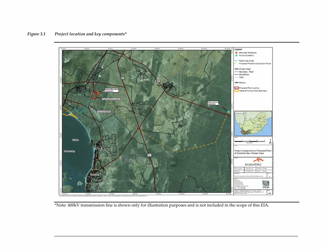
Figure 3.1 Project location and key components*
*Note: 400kV transmission line is shown only for illustration purposes and is not included in the scope of this EIA.

ENVIRONMENTAL RESOURCES MANAGEMENT CCGT POWER PLANT, SALDANHA
3-3
3.1.3 Land Ownership and Acquisition
The two properties on which the proposed power plant site is located are
detailed in Table 3.1.
Table 3.1 Properties which are intersected by the power plant footprint
Farm Name Portion Number Parcel Number SG Code
Yzervarkensrug 129 Remaining Extent W014C04600000000012900000
Jackels kloof 195 2 W014C04600000000019500002
The proposed pipeline corridor intersects with the properties as listed in Table
3.2.
Table 3.2 Properties which are intersected by the pipeline corridor
Farm Name Portion Number Parcel Number SG Code
None 0 1185 W014C046000000001185000000
STATE LAND 196 0 196 W014C046000000000196000000
HOPEFIELD 195 195 0 W014C046000000000195000001
HOPEFIELD 195 7 195 W014C046000000000195000070
Farm 195 1 195 W014C046000000000195000010
Jackals Kloof 195 2 195 W014C046000000000195000020
None 0 1132 W014C046000000001132000000
YZERVARKENSRUG 129 0 129 W014C046000000000129000001
The proposed feeder transmission line from the power plant to ArcelorMittal
Steel intersects with the properties as listed in Table 3.3.
Table 3.3 Properties which are intersected by proposed feeder transmission line from
the power plant to ArcelorMittal Steel
Farm Name Portion Number Parcel Number SG Code
YZERVARKENSRUG 129 0 129 W014C046000000000129000001
YZERVARKENSRUG 129 3 129 W015C046000000000129000030
None 0 1132 W014C046000000001132000000
3.2 PROJECT AREA OF INFLUENCE
For the purposes of this impact assessment, the definition of the Area of
Influence (AoI) encompasses:
• ‘The area likely to be affected by: (i) the project and the client’s activities and
facilities that are directly owned, operated or managed (including by contractors)
and that are a component of the project; (ii) impacts from unplanned but

ENVIRONMENTAL RESOURCES MANAGEMENT CCGT POWER PLANT, SALDANHA
3-4
predictable developments caused by the project that may occur later or at a
different location; or (iii) indirect project impacts on biodiversity or on ecosystem
services upon which Affected Communities’ livelihoods are dependent.
• Associated facilities are facilities that would not have been constructed or
expanded if the project did not exist and without which the project would not be
viable.
• Cumulative impacts that result from the incremental impact, on areas or resources
used or directly impacted by the project, from other existing, planned or
reasonably defined developments at the time the risks and impacts identification
process is conducted.’
For the Project, the direct AOI is the spatial extent of the Project footprint and
related facilities on the receiving environment. This encompasses:
• Power plant total surface area (area within the fence line);
• Pipeline construction (temporary) Right of Way (RoW); and
• 132kV feeder transmission line to ArcelorMittal RoW.
A breakdown of the surface areas for these components is provided in Table
3.1 and is shown later in this section in Figure 3.4.
Table 3.4 Footprint of project components
Project Component Area (ha)
Main Project Components
Power plant total surface area (area within the fence line) 45.83
Pipeline construction (temporary) RoW 30.49
Pipeline permanent easement 2.76
132kV feeder transmission line to ArcelorMittal RoW 7.22
Components within the power plant site
1.5 MW Generator 0.09
132KV Switchyard 2.40
440KV Switchyard 2.48
Admin, Control, Laboratory 0.25
Air-Cooled Condensers 1.56
Canteen, Changing Rooms, Ablutions 0.09
Clinic 0.01
Construction Changing Rooms & Ablution Block 0.18
Emergency Assembly Point 0.04
Gas Pipeline Receiving Area 0.18
Gas Turbine, Steam Turbine and HRSG Islands 1.89
Hard Standing Laydown Area 9.64
Laydown Area 0.69
Other 0.03
Pigging and Gas Metering Area 0.07
Reverse Osmosis, MSFD, Salt Residue 0.05
Sewerage Treatment Plant 0.12
Stormwater Collection Tanks 1.20
Trent Gas Turbines 0.73

ENVIRONMENTAL RESOURCES MANAGEMENT CCGT POWER PLANT, SALDANHA
3-5
Project Component Area (ha)
Truck Staging & Laydown Area 0.36
Visitors and Training Centre 0.07
Water Filtration 0.02
Water Treatment, Raw Water Storage, Fire Fighting Water 0.59
Workshop Warehouse and Spares 0.33
The indirect AOI encompasses areas potentially affected by cumulative
impacts as well as areas that could be impacted indirectly by Project activities.
The indirect AOI will differ between various resources and receptors
depending on the dependencies. For example, indirect impacts to soils would
be likely limited to the immediate areas around the direct footprint. Indirect
impact to social resources may however extend to nearby communities along
the coast which may be affected by the Project.

Figure 3.2 Project Area of Influence (AoI)

ENVIRONMENTAL RESOURCES MANAGEMENT CCGT POWER PLANT, SALDANHA
3-7
3.3 PROJECT COMPONENTS
The key project components considered in this EIA are as follows:
• Pipeline;
• Power plant; and
• Power evacuation and connection to the grid (1).
These are discussed in detail in the sections below. The general surface areas
for the project components are listed in Table 3.5 below.
Table 3.5 Project components general surface areas and lengths
Project Component
Area /
Length
Power Plant total surface area 45.83 ha
Length of pipeline 4.6km
Pipeline construction (temporary) RoW (36m width) 30.49 ha
Pipeline permanent easement (6m width) 2.76 ha
132kV feeder transmission line to ArcelorMittal length 2.4km
132kV feeder transmission line to ArcelorMittal RoW
(30m width) 7.22 ha
Proximity to grid connection 150m
It is envisaged that LNG will be supplied by ship to the Port of Saldanha
where it will likely be offloaded to a Floating Storage Regasification Unit
(FSRU). The FSRU will regasify the LNG and pump it via a pipeline to the
power plant. The supply of fuel and import facilities have not been considered
in this EIA. The Department of Energy initiated a project in 2015 to permit the
construction of an LNG import terminal at the Port of Saldanha, it was
understood that individual developers were not required to undertake the
EIA for this component. Should this information change, a separate EIA for
the import of gas will be undertaken.
3.3.1 Power Plant
General Configuration
Figure 3.4 shows the proposed plant layout. Current plans include six Trent 60
DLE (low NOx) 50 MW (installed gross capacity, refer to Box 3.1) gas turbines
in open cycle and three identical but independent 435MW SCC5 4000F
(installed gross capacity) single shaft generating trains in combined cycle.
Figure 3.3 shows the equipment configuration in a combined cycle system.
With reference to Figure 3.4 the corner points of the proposed power plant
boundary are listed in Table 3.6.
(1) Note: The transmission connection for Phase 1, i.e. the 132 kV connection to Saldanha Steel, is included in this EIA. The
transmission connection for Phase 2, i.e. the 400 KV connection to Eskom's Aurora substation, will be considered in a
separate EIA application. See Section 3.4 for details about the phases referred to here.

ENVIRONMENTAL RESOURCES MANAGEMENT CCGT POWER PLANT, SALDANHA
3-8
Box 3.1 Installed Gross Capacity vs Operating Capacity of the Power Plant
Figure 3.3 Combined Cycle Equipment Configuration
Source: Combined Cycle Process Description Flow, ArcelorMittal, 2015
The high temperature exhaust gases are captured at the outlet exhaust of each
gas turbine. This is fed into each HRSG via a short section of ductwork at the
exhaust outlet point. The HRSG is a triple pressure boiler comprising a high
pressure steam system, a reheat/medium pressure steam system and a low
pressure steam system. The hot exhaust gases will then transfer heat to water
in the HRSG, creating steam in the form of superheated high pressure (HP)
steam, reheat/medium pressure and low pressure (LP) steam. Steam from
each pressure level will be admitted to the steam turbine. A condenser will
convert exhaust steam from the steam turbines back into water.
The Installed Gross Capacity is normally the plant generating capacity at 100% loading and ISO
conditions. However, it is impossible to test ISO capacity performance in practice since the ISO
conditions of temperature, humidity and pressure very seldom occur together for the purposes
of testing. Installed gross capacity is the capacity at the generator terminals and is not the
energy despatched from the plant.
In the project development environment, power plant engineers consider the power demand of
the client and work backwards to design the plant with sufficient on-site capacity that will
produce sufficient despatchable power that will fulfil demand. In addition, plant design will be
based on site worst conditions, i.e. during summer at low barometric pressure and high
humidity. This is known as the Operating Capacity of the power plant.
Therefore, a more meaningful expression of capacity is performance at site conditions. The
Installed Gross Capacity of the proposed power plant is 1,605MW, and the Operating Capacity
is 1,507MW. This report will thus refer to the Operating capacity of the power plant throughout,
i.e. that of 1,507MW.

ENVIRONMENTAL RESOURCES MANAGEMENT CCGT POWER PLANT, SALDANHA
3-9
The plant will have an air cooled condenser system behind each steam
turbine.
Table 3.6 Co-ordinates of the corner points of the proposed power plant boundary.
Point Longitude Latitude
A 18° 2.521' E 32° 58.887' S
B 18° 2.755' E 32° 58.956' S
C 18° 2.765' E 32° 58.971' S
D 18° 2.759' E 32° 59.002' S
E 18° 2.823' E 32° 59.014' S
F 18° 2.675' E 32° 59.435' S
G 18° 2.398' E 32° 59.354' S
H 18° 2.410' E 32° 59.323' S
I 18° 2.350' E 32° 59.305' S

Figure 3.4 Power plant functional layout.

ENVIRONMENTAL RESOURCES MANAGEMENT CCGT POWER PLANT, SALDANHA
3-11
Table 3.7 Power Plant components and their respective footprint areas / lengths
Project Component Area
1.5 MW Generator 0.09 ha
132KV Switchyard 2.4 ha
440KV Switchyard 2.48 ha
Admin, Control, Laboratory 0.25 ha
Air-Cooled Condensers 1.56 ha
Canteen, Changing Rooms, Ablutions 0.09 ha
Clinic 0.01 ha
Construction Changing Rooms & Ablution Block 0.18 ha
Emergency Assembly Point 0.04 ha
Gas Pipeline Receiving Area 0.18 ha
Gas Turbine, Steam Turbine and HRSG Island 1 1.89 ha
Hard Standing Laydown Area 9.64 ha
Laydown Area 0.69 ha
Other miscellaneous infrastructure 0.03 ha
Pigging and Gas Metering Area 0.07 ha
Reverse Osmosis, MSFD, Salt Residue 0.05 ha
Sewerage Treatment Plant 0.12 ha
Stormwater Collection Tanks 1.2 ha
Trent Gas Turbines 0.73 ha
Truck Staging & Laydown Area 0.36 ha
Visitors and Training Centre 0.07 ha
Water Filtration 0.02 ha
Water Treatment, Raw Water Storage, Fire Fighting Water 0.59 ha
Workshop Warehouse and Spares 0.33 ha
Road surface area (total) 6.9ha
Propane storage vessels 3
Propane storage volume on site (total) 30 m2
Height of stacks 60m (max)

ENVIRONMENTAL RESOURCES MANAGEMENT CCGT POWER PLANT, SALDANHA
3-12
Project Component Area
Capacity of on-site substation
132 KV
substation for
phase 1 400
KV substation
for Phase 2
Type of perimeter fencing
ClearVu
Reinforced
Perimeter fence length 2.8km
Perimeter fence height 3 m
Power generation equipment
132 kV 300MWe Block
This consists of 6 x TRENT 60 DLE (low NOx) gas turbines. These will be the
first units to be installed. They will operate on natural gas in open cycle and
will be dedicated to supply ArcelorMittal. One gas turbine is a redundant unit
to ensure continuous uninterrupted supply.
At a later stage, it would be possible to convert at least two units to combined
cycle technology which would improve efficiency.

ENVIRONMENTAL RESOURCES MANAGEMENT CCGT POWER PLANT, SALDANHA
3-13
Figure 3.5 132kV, 300MWe Block layout (A) and 3D rendering (B)
A
B

ENVIRONMENTAL RESOURCES MANAGEMENT CCGT POWER PLANT, SALDANHA
3-14
400kV 1200 MWe Block
This consists of three identical but independent, SCC5-4000F single-shaft
generating trains, each providing 439 MWe net output capacity at 22kV net in
combined cycle configuration (1). The generated power will be stepped up to
400kV before being evacuated via the 400kV switchyard and through the
national grid network. The steam turbine exhaust is condensed by ACCs and
returned to the boiler feed storage tank in order to save on water
consumption.
Figure 3.6 400kV 1200 MWe Block layout (A) and 3D rendering (B)
Fuel is natural gas which will be piped up to the plant site at sufficient
pressure for feeding directly to the gas turbines by underground pipeline.
Emissions of CO2, NOx and CO are much reduced compared to coal-fired
power plants.
(1) Net gross capacity is 446 MW at ISO conditions 100% maximum continuous rating at average site conditions. The net
power output, i.e. operational power at 100% loading is 439 MW at average site conditions.
A
B
ENVIRONMENTAL RESOURCES MANAGEMENT CCGT POWER PLANT, SALDANHA
3-15
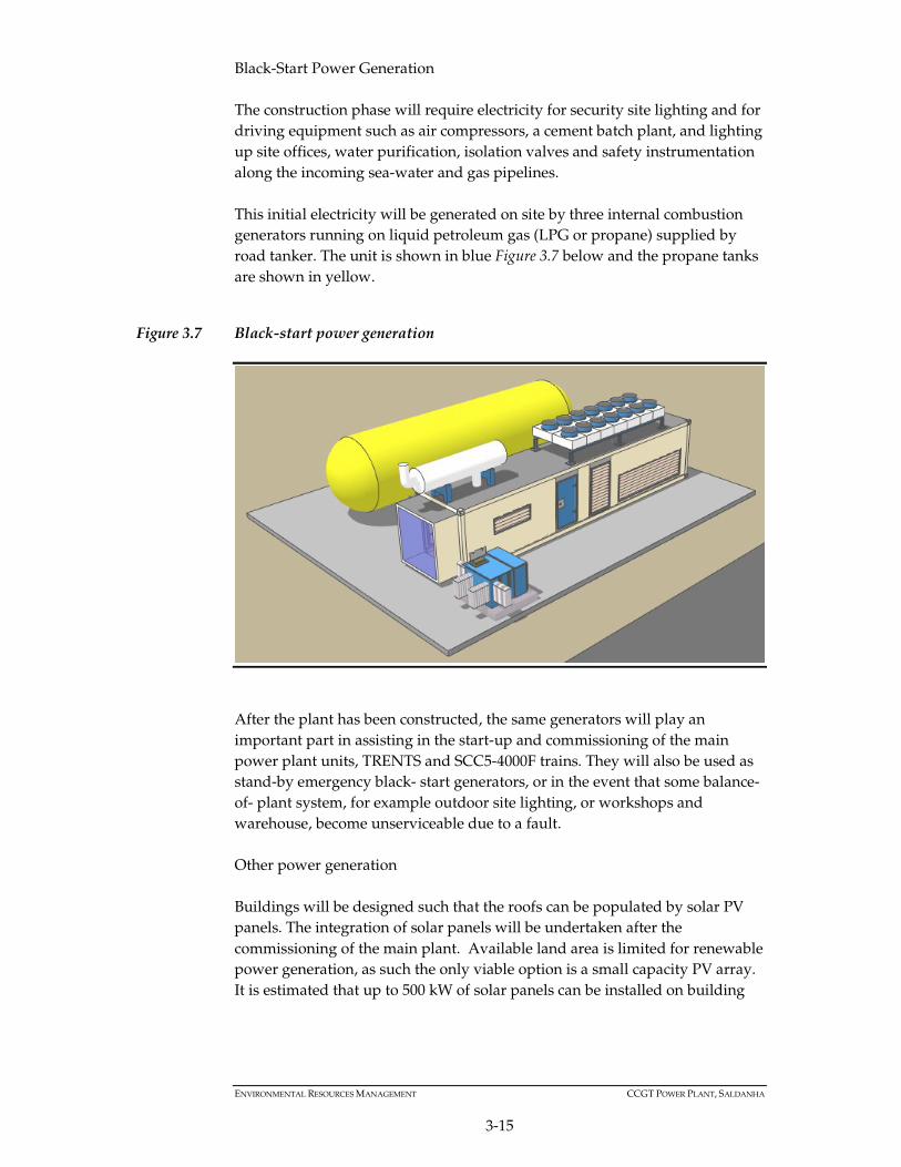
Black-Start Power Generation
The construction phase will require electricity for security site lighting and for
driving equipment such as air compressors, a cement batch plant, and lighting
up site offices, water purification, isolation valves and safety instrumentation
along the incoming sea-water and gas pipelines.
This initial electricity will be generated on site by three internal combustion
generators running on liquid petroleum gas (LPG or propane) supplied by
road tanker. The unit is shown in blue Figure 3.7 below and the propane tanks
are shown in yellow.
Figure 3.7 Black-start power generation
After the plant has been constructed, the same generators will play an
important part in assisting in the start-up and commissioning of the main
power plant units, TRENTS and SCC5-4000F trains. They will also be used as
stand-by emergency black- start generators, or in the event that some balance-
of- plant system, for example outdoor site lighting, or workshops and
warehouse, become unserviceable due to a fault.
Other power generation
Buildings will be designed such that the roofs can be populated by solar PV
panels. The integration of solar panels will be undertaken after the
commissioning of the main plant. Available land area is limited for renewable
power generation, as such the only viable option is a small capacity PV array.
It is estimated that up to 500 kW of solar panels can be installed on building

ENVIRONMENTAL RESOURCES MANAGEMENT CCGT POWER PLANT, SALDANHA
3-16
roofs, generating up to 800 MWh of solar power per year which will help
dissipate the plant’s parasitic loads (1) .
The excess solar power, not directly used on the plant, will be stored in the
latest generation of vanadium redox flow batteries and will assist to keep the
DC control and DC control back-up power system operational on a
continuous basis.
Some of the renewable solar power generated will be utilised in the following
facilities:
• Manufacture of hydrogen from sea water. Hydrogen is required on site for
the cooling of the large SGT5 generators;
• Desalination of sea water;
• Powering of a site-wide local WiFi LAN system for information gathering
and site- based communications;
• Powering of small local chemical dosing pumps;
• Main building LED lighting;
• Maintaining pressure of distributed potable water; and
• Charging the batteries of on-site electric personnel vehicles and cycles.
Figure 3.8 Example of the location of solar panels on building tops
Access routes and roads
The Project has accounted for certain road works, described below, deemed
necessary for safety and compliance with regional legislative requirements.
Permissions have not yet been sought for the proposed road works, the costs
(1) Parasitic load refers to the load generated by activities at the power plant which consume electricity, such as the office
buildings, workshops, water treatment plants, etc.

ENVIRONMENTAL RESOURCES MANAGEMENT CCGT POWER PLANT, SALDANHA
3-17
of which will be borne by the project and executed according to local Council
and/or Department of Roads and Traffic and/or Committee of Transport
Officials (COTO) regulations, requirements and guidelines; in particular Road
Infrastructure Strategic Framework for South Africa (RISFSA) of the South
African Department of Transport (DOT, 2006)
Figure 3.9 below shows the main access to the ArcelorMittal site branching
westwards off the R27. A secondary road crosses the access road and access to
the power plant is then southwards proceeding under the HV powerlines
from Blouwater substation to the southern entrance to the power plant site.
The access route indicated in Figure 3.9 will be most affected by increased
traffic, particularly from commencement of and during construction.
All of the approximately 6,900 m of road access on the 45.83 ha site will be
concrete- paved. The total area of roads is 5.59 ha which represents
approximately 12.4% of the fenced-in site area. Most roads are 8m width and
others 12m. The 12m concrete-paved roads will be constructed early after
commencement of construction works and will serve to carry heavy load
traffic (mobile cranes, multi axle heavy equipment trailers, cement delivery
trucks, etc.) during the early stages of construction.
All concreted roads will play an important role for rainwater harvesting, in
addition to the concreted lay-down areas. The site’s natural slope is towards
the south where the raw water storage tanks will be situated. The east-west
thoroughfares (‘streets’) will channel rainwater into the rain-water drains of
the north-south thoroughfares (‘avenues’). Rainwater will run southwards to
the bulk water storage tanks.
The grid-like road system serves to provide a more precise local description as
to the location of equipment, instrumentation or pipe-runs and a numbering
system on the curb stones will aid in instrument position identification.

Figure 3.9 Main access to the power plant via the R27

ENVIRONMENTAL RESOURCES MANAGEMENT CCGT POWER PLANT, SALDANHA
3-19
Approach to the Power Plant
For road safety considerations and in light of the increased traffic (particularly
during construction phase) the provincial road leading past the two power
plant entrances will be widened from 11 m to a 20 m wide over-taking 4- lane
section (Figure 3.10).
For the office and administration gate a wide entrance (12 m) and a 12 m
radius bend into the power plant site and offices from the access road to the
gate house is planned (Figure 3.11).
Figure 3.10 Illustration of widening of provincial road

ENVIRONMENTAL RESOURCES MANAGEMENT CCGT POWER PLANT, SALDANHA
3-20
Figure 3.11 Illustration of office and administration entrance
Main Goods and Construction Personnel Entrance
The widened provincial-road access approach, at full 12m width passes the
administration office entrance and the southern main goods entrance, detailed
below (Figure 3.12 A).
The drive-up from the main road to the site gate house is 135 m. A turnoff tees
off southwards (Figure 3.12 B).
Figure 3.12 (A) Widened provincial-road access to the Power Plant and (B) Main entrance
to Power Plant
A
B

ENVIRONMENTAL RESOURCES MANAGEMENT CCGT POWER PLANT, SALDANHA
3-21
Incoming Goods Traffic
Incoming goods traffic will pass over a weigh-bridge and will then be directed
to a temporary truck staging and laydown area for paper-work to be checked
before being directed to area of installation or unloaded at temporary
laydown area or in the event of electrical goods and instrumentation,
transferred by site transport and conveyed to the warehouse or workshops at
the north end of the site.
Admin /Office Building, DCS Control, Labs
With reference to Figure 3.13, plant administration offices housing (Figure
3.14), main Control Room, DCS marshalling panels, water laboratory, and two
meeting rooms, will initially be used during construction to house the offices
of construction managers and site engineers. Parking for up to 60 vehicles will
be provided under shade.
Figure 3.13 Access to Admin /Office Building, DCS Control, and Labs

ENVIRONMENTAL RESOURCES MANAGEMENT CCGT POWER PLANT, SALDANHA
3-22
Figure 3.14 3D rendering illustrating the administration and office entrance with the
permanent staff canteen and ablution block
Roads within the power plant complex
Within the power plant complex there are five different sizes of roads. This are
listed in Table 3.8 along with the cumulative length and surface area of each
road type.
Table 3.8 List of road types, lengths and surface areas within the power plant complex
Roads within the Power Plant Complex Length (m) Surface Area (ha)
Road type: 8m wide 4652.2 3.7
Road type: 10m wide 148.5 0.1
Road type: 12m wide 1414.2 1.7
Road type: 20m wide 490.4 1.0
Road type: 32m wide 120.1 0.4
Ancillary Facilities
In addition, the project will include the following plant / machinery
components:
• 132 KV Switchyard for 132 KV evacuation;
• 400KV Switchyard for 400 KV evacuation;
• Rain water treatment plant (Filtration);
• Sea-water treatment ( filtration);
• Sea-water desalination / RO (Reverse Osmosis) plant, 50 m3/hour;
• Post RO small –scale MSFD ( Multi-Stage Flash Distillation) Fire
Suppression system– water;
• Fire suppression - CO2 gas storage Fire suppression – foam Instrument air
compressors;

ENVIRONMENTAL RESOURCES MANAGEMENT CCGT POWER PLANT, SALDANHA
3-23
• Sewage treatment plant with water reclamation;
• Closed circuit air-cooling system ( compressor-less);
• Miscellaneous treated and untreated water tanks:
o Rain water storage tanks, total: 15,000 m3
o Demineralised water, total: 6,000 m3
o Fire water storage ( raw untreated water): 500 m3
o Boiler water for demin polishing: 3 x 100 m3
o Reclaimed water tank: 1 x 500 m3
o Filtered sea-water buffer tank: 300 m3
o RO-treated water tanks: 2 x 1,200 m3
• Other tanks
o Concentrated sulphuric acid 98%: 1000 litres S/S
o Dilute sulphuric acid: 1000 litres CS
o Ethylene glycol: 50 m3
o Ammonia: 20 m3
• Site security, fencing (Figure 3.15), surveillance and communications.
Figure 3.15 Illustration of the fencing that will be used ('Clear Vu', 3m high)
Table 3.9 List of buildings associated with the power plant
Building Dimensions
Power generation buildings x 3 55m L x 30m W x 25m H
Main office and control Centre footprint 2500 m2 , floor space 4,000 m2
Gate house x 2 Total area 156 m2 at each gate
Permanent staff Canteen, Kitchen
Ablutions: 825 m2
Workshop 1,500 m2
Spares & warehouse 1,500 m2
Chemical storage 200 m2
Various SSB rooms (system and switch-boards) (pending)

ENVIRONMENTAL RESOURCES MANAGEMENT CCGT POWER PLANT, SALDANHA
3-24
Building Dimensions
Site electric vehicle charge center (pending)
Training and visitor’s center 300 m2
Site first aid and medical clinic 120 m2
132 KV switchyard control and instrumentation
room
(pending)
400 KV switchyard control and instrumentation
room
(pending)
Gate house
The gate house will be set back approximately 135 m from the edge of the
road. The gate-house will be manned 24 hrs/day. The gate house, covering
50 m2 on each side of the road, is fitted with a restroom, ablutions and a
surveillance office. The gate house will be is fully equipped with video
surveillance for a team of four persons per shift. A gate alarm at 30 m from the
gate office will alert the gate staff of a vehicle approach.
Water facilities
Water facilities will have a common source and consists of several discrete
water systems. Two areas on the power plant site have been allocated to water
treatment. The first area (Figure 3.16) is primarily for storage and treatment of
raw rain water and is adjacent to the gas receiving station at the south end of
the site.
This area receives:
• Surface rain water which is stored in a series of five 2 000 m3
interconnected water tanks;
• Fresh water (not necessarily municipal) brought onto site by road tanker;
• Sea-water to be used in the zero liquid discharge (ZLD) desalination or
other process; and
• Reclaimed water from the site sewage plant.

ENVIRONMENTAL RESOURCES MANAGEMENT CCGT POWER PLANT, SALDANHA
3-25
Figure 3.16 Water storage tank layout (A) and 3D rendering (B)
Storm water will be the main source of rain water to be stored in the
interconnected water tanks. The site has a natural north to south gradient of
approximately 1%. The site will be slightly graded to form a symmetrical V-
shaped slope. Figure 3.17 illustrates the drainage pattern of an imaginary sheet
of water draining down the ungraded slope of the site.
Internal roads will be contoured to channel precipitation towards storm-water
drainage points along the road curb. Storm water will flow into a single
enclosed duct which will dump the water into a grit- pit. From the grit-pit
dual submersible pumps (actuated by level controllers) will pump the water
through coarse filters into the five interconnected steel water tanks situated at
the most southern boundary of the property.
The pumps and drain ducts will be sized to cope with the maximum
anticipated flow of rain water.
A stone-filled emergency soak-away channel will be constructed along the
southern-most boundary to channel excess storm water (in case of an unusual
rainfall event) away from the site. The soak-away channel will dissipate the
energy of the water to prevent soil erosion.
A
B

ENVIRONMENTAL RESOURCES MANAGEMENT CCGT POWER PLANT, SALDANHA
3-26
Figure 3.17 Surface Water Drainage
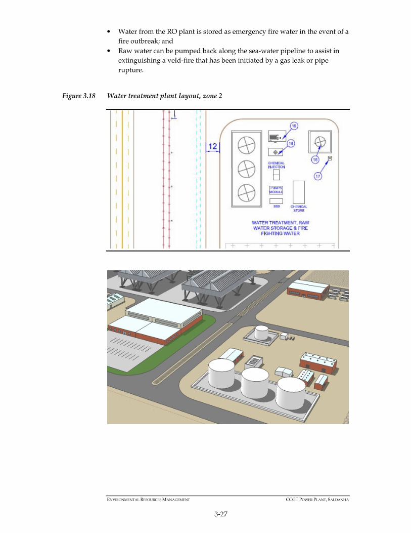
The second area is for final water treatment, demineralisation and storage of
water for fire abatement. After being processed by reverse osmosis (RO),
purified water is pumped to zone two (top left in Figure 3.18).
• In this area, water from RO is deionised, chemically treated and stored for
boiler feed water condensed steam is deionised, re-treated, stored and
reused as boiler feed;
• Deionised water is stored for the lube-oil cooling circuit;
• Deionised water is distributed to day tanks close to the boilers and
generation plant;
ENVIRONMENTAL RESOURCES MANAGEMENT CCGT POWER PLANT, SALDANHA
3-27
• Water from the RO plant is stored as emergency fire water in the event of a
fire outbreak; and
• Raw water can be pumped back along the sea-water pipeline to assist in
extinguishing a veld-fire that has been initiated by a gas leak or pipe
rupture.
Figure 3.18 Water treatment plant layout, zone 2

ENVIRONMENTAL RESOURCES MANAGEMENT CCGT POWER PLANT, SALDANHA
3-28
Natural Gas
This EIA is for the CCGT gas-fired power plant and gas pipeline only and
does not include the import of gas and therefore a marine component (1). The
project operating company will take possession of the natural gas at the point
where it comes on shore and enters the on-shore gas pipeline to the plant site.
Natural gas will be piped to the power plant through a twin, 250 mm Ø
nominal gas pipeline at entry gas pipeline-pressure of 90 barg and at a
maximum rate of 60 kgs /sec and a temperature of -20ºC. The gas flow will
follow the power demand load.
Figure 3.19 Gas pipeline entry to the power plant site
The red dot in the Figure 3.19 indicates where the gas pipeline is diverted
towards the plant site boundary. At a pressure ranging between 45 barg and
60 barg the gas traverses under the newly widened access road, passing under
the double security fence and surfacing aboveground as it proceeds to the gas
receiving area above the main entrance gate.
At about -20 °C, the gas is heated to near ambient by cooling a 30 % glycol
solution to -15 °C before being piped to the gas turbines for combustion.
(1) It is anticipated that potential impact on the marine environment will be considered as part of the Department of Energy
gas to power project. The Department of Energy (DoE) has developed a 20-year energy plan for South Africa, the
Integrated Resources Plan 2010-2030 (IRP 2010), which encourages the participation of independent power producers
(IPPs) in electricity generation in South Africa. The Independent Power Producers (IPP) Office was established by the DoE,
the National Treasury and the Development Bank of Southern Africa (DBSA) to facilitate the involvement of IPPs in the
generation of electricity. It is currently intended that 3126 MW of new generation capacity will be generated from natural
gas. For the Gas IPP Procurement Programme, the DoE through the IPP Office has, in collaboration with Transnet,
developed an approach to facilitate the import of LNG to allow for the development of medium- to long-term gas power
plants outside of the port boundaries. This EIA therefore forms a separate application by a private company for gas power
plants and related infrastructure near the Port.

ENVIRONMENTAL RESOURCES MANAGEMENT CCGT POWER PLANT, SALDANHA
3-29
Propane
As discussed above, three 1.5 MW gensets are proposed. These will be
situated near the workshops in the north of the site, near the air condensers in
the middle of the site and near the water storage facility near the south of the
site. LPG (Propane) will be trucked on to site by road tanker and stored in
three tanks cumulatively not exceeding 30 m3 in volume.
3.3.2 Pipeline
General
The pipeline transport system from the point of arrival on-shore to the power
plant site will consist of the following:
• A gas and sea-water forwarding station at the start of the land-based
pipeline system;
• A dual, parallel gas pipeline for security of gas supply;
• A 120mm diameter sea water pipeline to provide the power plant with sea
water for desalination (rated maximum flow rate will be 14 litres per
second);
• A power cable to provide motive power for a projected air compressor and
actuated isolation valves and instrumentation along the pipeline route;
and
• A gas and sea-water receiving station at the power plant.
The LNG pipeline (regasified gas) and sea-water supply servitude will run
from the pipeline entry point connecting to the power plant boundary. The
gas pipeline will be buried to a depth of 3 to 4 m, cover a servitude width of
approximately 15 – 20 m and be approximately 4600 m in length.
The gas and sea-water supply pipelines commence from the routing point #1,
where the regasified LNG arrives on shore and enters the land-based
servitude section of the supply line to the 1507 MW power plant.
The pipeline will run along the indicated servitude approximately 4600 m to
the gas receiving station within the power plant boundary. Over the 4600 m
the pipeline will not intersect with any water courses.
The gas-carrying capacity of the pipeline for the envisaged 1507 MW power
plant will be designed for 75,100 Nm3 /hr or approximately 65 Kg/sec of
regasified LNG (regasification of LNG will take place offshore). The
management and operation of the gas pipeline will be in accordance with
ASME B31.BS code of practice. The proposed pipeline system will be buried
underground with the pipeline servitude extending 6m on either side of the
pipeline trench.

ENVIRONMENTAL RESOURCES MANAGEMENT CCGT POWER PLANT, SALDANHA
3-30
Where the pipeline passes through sensitive areas the temporary RoW will be
kept to between 20-25m in order to minimise impacts.
Table 3.10 Co-ordinates of the proposed pipeline
Point Number South East
#1 33° 0.075'S 18° 0.932'E
#2 33° 0.378'S 18° 1.457'E
#3 33° 0.379'S 18° 1.687'E
#4 33° 0.079'S 18° 1.687'E
#5 32° 59.912'S 18° 2.059'E
#6 32° 59.264'S 18° 2.325'E
#7 32° 59.278'S 18° 2.382'E
Pipeline arrangement concept
The pipeline arrangement (Figure 3.20) will consist of the following elements:
• Two steel gas pipelines with a clearance of 0.3m (as per EN 1594:2000);
• One steel water pipeline; and
• One electrical conduit (plastic compound).
Figure 3.20 Illustration of the pipeline arrangement concept
Design parameters
The main design parameters for the pipeline are listed in Table 3.11 below.
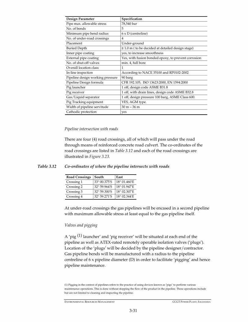
Table 3.11 Gas pipeline main design parameters
Design Parameter Specification
General safety rules 49CFR parts 191, 192, 193 and
General design code ASME B31.8
Pipeline material API 5L, ISO 3183, ISO 1208, ( sch. 40) or EN equivalent
Pipeline nom. Diameter, D 2 x 300 mm
Wall-thickness 10.31 mm
Operating design press. 90 bar
ENVIRONMENTAL RESOURCES MANAGEMENT CCGT POWER PLANT, SALDANHA
3-31
Design Parameter Specification
Pipe max. allowable stress 78,540 bar
No. of bends 5
Minimum pipe bend radius 6 x D (centreline)
No. of under-road crossings 4
Placement Under-ground
Buried Depth ≥ 1.0 m ( to be decided at detailed design stage)
Inner pipe coating yes, to increase smoothness
External pipe coating Yes, with fusion bonded epoxy, to prevent corrosion
No. of shut-off valves min. 4, full bore
Overall location class 1
In-line inspection According to NACE 35100 and RP0102-2002
Pipeline design working pressure 90 barg
Pipeline Design formula CFR 192.105, ISO 13623:2000, EN 1594:2000
Pig launcher 1 off, design code ASME B31.8
Pig receiver 1 off, with drain lines, design code ASME B32.8
Gas/Liquid separator 1 off, design pressure 100 barg, ASME Class 600.
Pig Tracking equipment YES, AGM type.
Width of pipeline servitude 30 m – 36 m
Cathodic protection yes
Pipeline intersection with roads
There are four (4) road crossings, all of which will pass under the road
through means of reinforced concrete road culvert. The co-ordinates of the
road crossings are listed in Table 3.12 and each of the road crossings are
illustrated in Figure 3.23.
Table 3.12 Co-ordinates of where the pipeline intersects with roads
Road Crossings South East
Crossing 1 33° 00.375'S 18° 01.460'E
Crossing 2 32° 59.964'S 18° 01.947'E
Crossing 3 32° 59.300'S 18° 02.307'E
Crossing 4 32° 59.271'S 18° 02.344'E
At under-road crossings the gas pipelines will be encased in a second pipeline
with maximum allowable stress at least equal to the gas pipeline itself.
Valves and pigging
A ‘pig (1) launcher’ and ‘pig receiver’ will be situated at each end of the
pipeline as well as ATEX-rated remotely operable isolation valves (‘plugs’).
Location of the ‘plugs’ will be decided by the pipeline designer/contractor.
Gas pipeline bends will be manufactured with a radius to the pipeline
centreline of 6 x pipeline diameter (D) in order to facilitate ‘pigging’ and hence
pipeline maintenance.
(1) Pigging in the context of pipelines refers to the practice of using devices known as "pigs" to perform various
maintenance operations. This is done without stopping the flow of the product in the pipeline. These operations include
but are not limited to cleaning and inspecting the pipeline.
ENVIRONMENTAL RESOURCES MANAGEMENT CCGT POWER PLANT, SALDANHA
3-32
Isolation valves for the gas pipelines will be carefully selected from a range of
appropriate through-conduit gate valves, wedge gate or parallel slide valves
in order to accommodate and not obstruct the passage of the ‘pig’. Check
vales, if required in the gas pipeline, require that the flow area within the
valve body be larger than the pipe inside diameter. The valves will be
remotely actuated. Applicable standards are API, ASTM, ANSI/ASME, and in
particular, for design and hazard analysis, API RP14J and API RP14C.
The gas pipeline being only 4600 m in length will have isolation valves
positioned at the start of each pipeline, in the middle and at the receiving end
(these are in addition to the isolation valves at the pigging stations). The
valves will be automatically actuated as programmed by the pipeline
designer/EPC contractor.
Valves and non-return valves for the sea-water pipeline will be manufactured
from specialist alloys and will also be through-conduit. Valves for sea-water
application will be in accordance with API, ANSI/ASME or ISO specifications.
The sea-water pipeline will also be designed for ‘pig’ functionality.
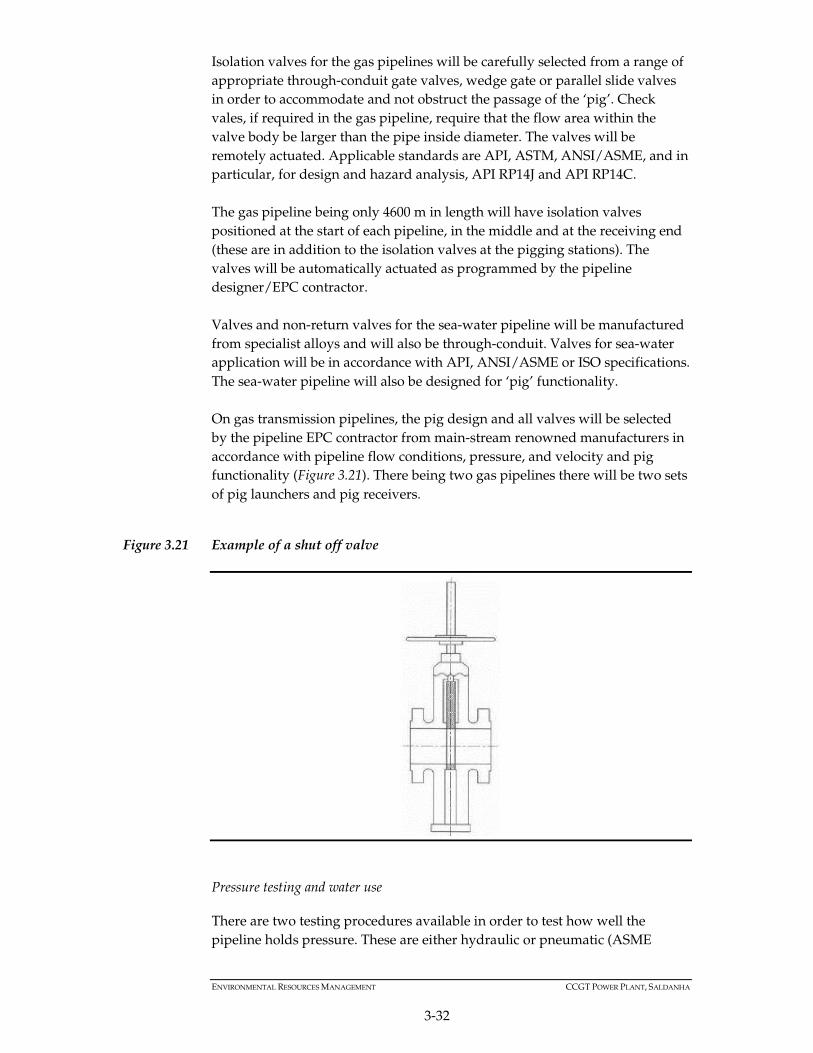
On gas transmission pipelines, the pig design and all valves will be selected
by the pipeline EPC contractor from main-stream renowned manufacturers in
accordance with pipeline flow conditions, pressure, and velocity and pig
functionality (Figure 3.21). There being two gas pipelines there will be two sets
of pig launchers and pig receivers.
Figure 3.21 Example of a shut off valve
Pressure testing and water use
There are two testing procedures available in order to test how well the
pipeline holds pressure. These are either hydraulic or pneumatic (ASME

ENVIRONMENTAL RESOURCES MANAGEMENT CCGT POWER PLANT, SALDANHA
3-33
Section B31.1). From a technical perspective the hydraulic method is preferred
because it has a lower level of potential energy than the pneumatic method
thus it is safer. However, hydraulic testing will require 2,100 m3 of fresh water
per pipeline. However, after use, this can be pumped to the power plant
water reservoir through the sea-water pipeline.
The pneumatic test, while not requiring water, requires multiple compressors
to pressurise the pipeline and a high power feed or considerable diesel fuel for
the compressors. The method of pipeline pressure testing will be decided
upon by the EPC contractors based upon an analysis of the pros and cons of
each method.
Cathodic protection and corrosion monitoring
Cathodic Protection (CP) is a technique used to control the corrosion of a
metal pipeline by making it the cathode of an electrochemical cell. A simple
method of protection connects the metal to be protected to a more easily
corroded "sacrificial metal" to act as the anode.
CP requires the highest priority and most appropriate protection system for
gas pipelines. The guidelines for this protection are provided by NACE
International, the worldwide Corrosion Authority and will be implemented
by the pipeline EPC contractor who will be guided by specialised
consultancies.
Along a pipeline the corrosion protection system will be monitored after the
selected corrosion system has been installed in order to obtain early warning
of corrosion issues and maintain pipeline integrity. Therefore, an online, real-
time corrosion monitoring system will be installed. The online, real time
corrosion monitoring data sensors and measurement devices will be installed
at strategic points along the pipeline. These strategic points are in turn
identified by ICDA (Internal Corrosion Direct Assessment) methods.
Because the natural gas that will be utilised by the power plant derives from
regasification of LNG, water content in the gas is zero (regasified LNG does
not contain any moisture). This is also evidenced by the analysis of the LNG
that will be supplied under contract to the project (Table 3.13). Therefore the
effects of corrosion on the inside of the pipe due to the presence of water in
the gas stream can effectively be discounted. In addition, the Inner pipeline
surface will be coated with a protective epoxy layer.
Table 3.13 Analysis of contracted gas supply
Component
Mole %
Original Dry Normalised
Compn. + / - Dry Wet
Methane 96.109 96.109 95.53
Ethane 1.807
1.807 1.796

ENVIRONMENTAL RESOURCES MANAGEMENT CCGT POWER PLANT, SALDANHA
3-34
Component Mole %
Propane 0.164
0.164 0.163
iso-Butane 0.028 0.028 0.028
n-Butane 0.028 0.028 0.028
iso-Pentane 0.011 0.011 0.011
n-Pentane 0.007 0.007 0.007
n-Hexane 0.008
0.008 0.008
n-Heptane 0.013 0.013 0.013
Nitrogen 0.357 0.357 0.355
Carbon Dioxide 1.468 1.468 1.459
Water 0.603

Figure 3.22 Pipeline Route

Table 3.14 Servitude sections and elevation profiles
Servitude Section Description Servitude Section Illustration
#1 - #2: 923 m Situated on the S – W side of the dirt
road.
Pig-Launching station is located at point #1
Note: that the LNG pipeline through Transnet land will
be permitted separately. AMSS will liaise with Transnet
to ensure that a coordinated approach will be followed.
#2 - #3: 990 m Situated on the S – E side of the road
running S-E

Servitude Section Description Servitude Section Illustration
#3 - #4: 660 m across open non sensitive field.
Under-road crossing 1
#4 - #5: 665 m Under-road crossings 2 and 3.

Servitude Section Description Servitude Section Illustration
#5 - #6: 1,270 m + 95 m. to E-side of main site access
road. Under-road crossing 4
Pig-receiving station is located at point #1

Figure 3.23 Location of the pipeline road crossings

3.3.3 Power Evacuation and Connection to the Grid
132 kV Feeder line to ArcelorMittal Steel Works
The feeder power line for the initial 160 MW base load (peaking to 250 MW)
from the power plant to the ArcelorMittal Steel Works will be the first priority.
This 132 kV feeder line will be sized for a capacity of 400 MW. The proposed
routing of the transmission line is illustrated in Figure 3.24, and the
coordinates of the vertices for this transmission line are presented in Error!
Reference source not found..
The proposed Project plans on utilising the existing 132 KV lines; towers and
conductors. The 132 kV plant substation would join directly on to these
existing lines. It is noted that there are currently no observed bird deterrent
measures on the existing lines. This may need to be introduced; however this
would need to be determined between IPCSA and Eskom.
Table 3.15 Coordinates of the vertices for the proposed transmission line from the power
plant to the ArcelorMittal Steel Plant
Point Longitude Latitude
FL1 18° 2.736' E 32° 58.992' S
FL2 18° 2.780' E 32° 58.943' S
FL3 18° 2.508' E 32° 58.667' S
FL4 18° 2.054' E 32° 58.506' S
FL5 18° 1.512' E 32° 58.598' S
400 kV Transmission line to Aurora Substation
The additional 1103MW (1400MVA) of power generated at the plant will be
evacuated through the construction of a new 22 km High Voltage (HV) 400
kilo Volt (kV) line from the power plants own switch yard to the existing
Aurora 400 kV substation, following the existing Aurora to Blouwater 132 kV
feeder servitude. This transmission line in not considered as part of this EIA
process and will be considered in a separate EIA process in coordination with
Eskom.

Figure 3.24 132kV feeder transmission line from the power plant to ArcelorMittal Steel Works

3.4 PROJECT PHASING AND SCHEDULE
The proposed project will be implemented in two phases. Phase 1 and 2
combined will produce approximately 1500 MW net out-put.
Phase 1 and 2 will consist of six Siemens Trent60 50 MW nominal (Installed
Gross capacity) gas turbines in open cycle (labelled T1 through to T6) and
three Siemens SCC5-4000F 435 MW (Installed Gross capacity) nominal
combined cycle plants, labelled UNIT 1, UNIT 2 and UNIT 3 respectively, and
will be erected on three self-contained power ‘islands’ each approximately 150
m long x 60m wide.
3.4.1 Phase 1
Phase 1 of the project will constitute the following components:
• Site entrance with truck staging areas, hard standing areas;
• Offices and control room;
• Warehouse areas and workshops;
• Installation of six open cycle Siemens Industrial Trent 60 gas turbines (T1,
T2, T3, T4, T5 and T6), one of which will be a redundant unit to ensure
uninterrupted supply;
• Associated step-up transformers for every generating unit;
• 132KV and 400 kV switchyard;
• Site drainage;
• Gas receiving, conditioning and forwarding;
• Waste-Water treatment and water reclamation plant; and
• Storm water collection reservoir (25,000 m3) and water treatment plant.
Construction period: 15 -18 months
On-site labour: 90 - 200
Completion Phase 1: September 2019 commercial operation
3.4.2 Phase 2
Construction of Phase 2 of the project will include the following components:
• Installation of complete UNIT 1, UNIT 2 and UNIT 3 open cycle Siemens
SCC5-4000F gas turbine (total approx. 1,305 MW nominal (Installed Gross
capacity) combined cycle plants);
• Associated step-up transformers, and station switchyard.
Construction period: 18 - 20 months
On-site labour: 200 - 600
Completion Phase 2: Mid- 2020 - Early 2021

3.5 PROJECT IMPLEMENTATION
The project will be undertaken in a number of stages, commencing with
development (i.e. the work undertaken directly by IPCSA up to bankable
feasibility which will also include a Front End Engineering Design) with up to
20 full-time staff at most. All other collaborators will be contracted third-party
engineers, accountants and draughtsmen as well as various OEM staff and
legal advisors. Thereafter the site preparation activities will be undertaken, as
described below.
3.5.1 Site Preparation
Site clearance activities include clearing the land of vegetation, fencing the
project boundary and site levelling. Internal site roads will be constructed as
the site levelling will require a number of heavy trucks to bring infill to the
site and remove unnecessary material.
3.5.2 Construction Phase
Site roads constructed during the site preparation phase will be used to
transport the heavy plant equipment required during the construction phase.
In addition, earthworks will follow the site clearance earthworks and include
the excavations necessary to achieve the works (e.g. for foundations) and the
backfilling after completion of these works.
Construction schedule
The Project development will take approximately four years to complete. This
is illustrated in Figure 3.25 below.

Figure 3.25 High level Project development schedule
Contr
act
Year 4
Q1 Q2 Q3 Q4 Q3 Q4 Q1 Q2 Q3 Q4Q1 Q2 Q3 Q4 Q1
Preliminary
Development Power Plant Phase 1 - Trent x 6
Year 1 Year 2 Year 3
Q2
Sewerage Plant Workshops Phase 2 - SGT5 - 4000F - UNIT 3
Site Facilities 132kV OHTL Phase 2 - SGT5 - 4000F - UNIT 1
Phase 2 - SGT5 - 4000F - UNIT 2
Admin Building and Office
Block Water Reservoir RO Plant Pipeline
Power Plant Phase 2 - buildings
Site Preparation and Levelling
132 kV Switchyard
400 kV Switchyard
400 kV Overhead Transmission Lines
400 KV Sub-station (Eskom)

ENVIRONMENTAL RESOURCES MANAGEMENT CCGT POWER PLANT, SALDANHA
3-45
Water requirements
During the construction phase the main water requirement will be for the
concrete batching plant. It is estimated that 30 000m3 of water will be required
for the concrete batching.
During the commissioning phase the following water will be required:
• 2,000 – 5,000 m3 for blow-out of the steam piping
(Testing/commissioning);
• 2,000 – 5,000 m3for blow out and chemical clean of the Benson boilers; and
• 23 000m3 (approximately) for pipeline cleaning and hydraulic pressure
testing.
Initially water will be trucked in 30m3 loads from local farms (ground and
surface water sources) (1). It will be transferred to a temporary stainless-steel
tank for immediate use in preparing concrete for a small lay-down area and
foundations for the first permanent raw-water storage tanks.
Power plant
Foundations and Piling
Piling of the foundations ( if required) for the first six Siemens Industrial Trent
60 gas turbines (T1 through to T6), the other gas turbines (Siemens SCC5-
4000F, UNIT 1 to 3) and large main equipment items, will last for
approximately 10 months until the foundations for the last item of equipment
have been completed. Once the piles are in place, concrete slabs will be
constructed and turbine pedestals constructed which will involve some large
pours of concrete. At this stage the gas turbine main building will be
constructed which will be the first visible building associated with the power
plant. The Siemens Industrial Trent 60 gas turbines will not be enclosed in
buildings.
Site hard standing
The construction phase will require substantial laydown hard-standing area
for temporary placement of equipment and materials delivered to site. Several
areas are demarcated as ‘laydown areas’ (Figure 3.4) but will used as such
only during the construction phase. Laydown areas will be concreted to aid in
rain-water harvesting.
After commissioning is completed, the hard-standing areas will be
rehabilitated and available for any plant expansion which may be subject to
additional EIA application.
(1) Agreements with land owners are currently in the process of being developed.

ENVIRONMENTAL RESOURCES MANAGEMENT CCGT POWER PLANT, SALDANHA
3-46
Total hardstanding area is approximately 10.7 ha representing approximately
23.6 percent of the total site area. All hard-standing areas will drain into the
rain-water collection system. Concreting over the hard-standing area will
reduce dust especially during construction and will play a major role in rain
water harvesting after the plant is in commercial operation.
Traffic
Approximately 35,000 tons of bulk cement and concrete aggregate, 800 tons re-
bar steel, and 6,500 tons equipment and structural steel will need to be
transported to the construction site.
Figure 3.26 Access during construction period
It is envisaged that construction staff, up to a maximum of 350 persons, would
be bussed to site in 8-seater or 10- seater mini busses and pass through this
gate; about 40 - 50 busses per day, twice a day. Light vehicle traffic due to
construction will start at around 35 vehicles per day and increase rapidly to 60
per day where it will remain for the bulk of the construction period.
There will be an expected 5 vehicles per day of HGV’s, bulk gravel, bulk sand,
and bulk cement respectively for the duration of the construction phase right
up to Q1 of year 4, after which it tails off rapidly.
The gas turbines and other heavy equipment will be delivered via truck. This
will involve some abnormal loads being moved on the roads during this time.

ENVIRONMENTAL RESOURCES MANAGEMENT CCGT POWER PLANT, SALDANHA
3-47
Figure 3.27 Predicted traffic loads during the construction phase
Employment
During peak construction activity, it is expected that up to approximately 450
workers will be directly employed (Figure 3.28). Most of this workforce will be
employed by the engineering, procurement and construction (EPC) contractor
and will consist in semi-skilled to skilled workforce.
1724
3847 49 49 49 49 49
41 40 3728
2012
35
40
45
60 60 60 60 60 60
60 60
40
40
40
28
2
2
2
4 4 5 5 5 5
5 5
3
3
1
1
1
1
1
1 1 1 1 1 1
1 1
1
1
15
5
5
5 5 5 5 5 5
5 5
5
5
5
5
5 5 5 5 5 5
5 5
5
5
5
5
5 5 5 5 5 5
5 5
5
0
20
40
60
80
100
120
140
Q1 Q2 Q3 Q4 Q1 Q2 Q3 Q4 Q1 Q2 Q3 Q4 Q1 Q2 Q3 Q4
Ve
hic
les
pe
r d
ay
Construction Timeline (Quarterly)
Construction Traffic
Bulk cement
Bulk gravel
Bulk sand
E.H.G.V
H.G.V.
Light Vehicles
Busses

ENVIRONMENTAL RESOURCES MANAGEMENT CCGT POWER PLANT, SALDANHA
3-48
Figure 3.28 Employment requirements during the construction phase
Commissioning
After approximately 28 month’s general site activity will decrease as the
project moves into full commissioning where there will be a relatively small
group of highly skilled engineers and technicians checking, testing, starting-
up and finally commissioning the power plant.
Phase 1:
• The first Siemens Industrial Trent 60 gas turbine units (300 MW) will be
commissioned within twelve to fourteen months from financial close.
Phase 2:
• The three Siemens SCC5-4000F units (UNIT 1, UNIT 2 and UNIT 3) will be
commissioned twelve to fourteen months after Phase 1.
The current timeline estimates 48 months construction for Phase 1 and Phase 2
combined.
Pipeline Installation
Pipelines will be installed underground, and this implies the opening of a
working strip along the right of way of the pipeline. During construction, the
excavated trench will be clearly indicated and access and passage through the
12 12 12 12 12 12 12 12 12 12 12 12 12 12 128 8 8 8 8 8 8 8 8 8 8 8 8 8 8
15 20 2540 40 40 40 40 40 40 40
20 20 20 8
3050
120
190210 210 210 210 210
175 170
150
80
40
20
40
40
80
80
80 80 80 80 80
50 50
40
40
20
20
60
100
100
100
100 100 100 100 100
100 100
100
100
100
50
0
50
100
150
200
250
300
350
400
450
500
Q1 Q2 Q3 Q4 Q1 Q2 Q3 Q4 Q1 Q2 Q3 Q4 Q1 Q2 Q3 Q4
Nu
mb
er
of
Em
plo
ye
es
Construction Timeline (Quarterly)
Construction Employees
Unskilled
Semi-skilled
Skilled
Technicians
Engineers
Admin

ENVIRONMENTAL RESOURCES MANAGEMENT CCGT POWER PLANT, SALDANHA
3-49
area will be restricted. The servitude is expected to 36 m in width (1) (including
width of the pipe trench itself). Figure 3.29 provides an overview of an
indicative working strip for pipe laying.
The centreline of the trench need not coincide with the centreline of the
servitude space requirement during construction, but may be situated closer
to one side or the other of the servitude, depending on traffic and access,
excavation programme and volume of topsoil and excavated soil. The pipeline
trench is likely to have a width of 2 meters and a depth of between 1.5 m –
2 m (2). Generally speaking the deeper the trench, the more work space will be
required.
The boundaries of the servitude route will be clearly marked, flagged, or
posted, such that each mark will be clearly visible from each mark on either
side of it along the route. Markings on each flag or post along the route will be
consistent with best management practice and may emphasise specific
location warnings or conditions. Traffic through active work areas along the
route will be strictly controlled.
Figure 3.29 Indicative working strip
Source: ERM (2015) (drawing not to scale)
Table 3.16 provides a step by step description and illustration of the pipeline
construction process. Prior to construction of the pipeline commencing
surveying of the pipeline route will take place. Based on the information
gathered during the surveying process which takes into account, amongst
other things, environmental, developmental and local issues, a final route is
developed.
The EPC contractor will ultimately decide on the construction method to be
used and is typically dependant on subsurface ground characteristics.
Excavated sub-surface soil will be stored separately from the top-soil and
large rocks, if any, may be removed and added later during the padding and
back-fill stage. The slope and depth of the ditch will be in accordance with
(1) The precise width will be determined by the EPC contractor after taking into account local ground and flora conditions
and his projected site traffic estimates during construction (2) Exact dimensions will be determined by the EPC contractor after geotechnical investigations.

ENVIRONMENTAL RESOURCES MANAGEMENT CCGT POWER PLANT, SALDANHA
3-50
stipulated safety requirements which the EPC contractor will be acquainted
with. From preliminary charting studies, blasting will not be required.
Road crossings will be designed by the EPC contractor according to
ASME B31.4 and API RP 1102 or EN equivalent or as dictated by the Roads
Authority. However, asphalt road crossings are usually carried out by a
‘boring’ method and crossings of gravel roads are typically by an ‘open cut’
method depending on traffic conditions and local regulations. Separate boring
will be required for the sea-water pipeline and for the electrical cable conduit.

ENVIRONMENTAL RESOURCES MANAGEMENT CCGT POWER PLANT, SALDANHA
3-51
Table 3.16 Illustration of the pipeline construction process
Process Description Illustration
Grading of the Right-of-Way:
The topsoil along the right-of-way is stripped and stored for
replacement following the installation of the pipeline.
Laying out the pipe:
Crews then re-stake the centre of the trench area and lay-out
sections of the pipe along the right-of-way.

ENVIRONMENTAL RESOURCES MANAGEMENT CCGT POWER PLANT, SALDANHA
3-52
Process Description Illustration
Pipe preparation:
Crews weld the sections of pipe into longer sections that follow the
planned route. Individual sections have already been coated to
prevent corrosion. Crews weld the sections of the pipe in mobile
welding cabins to prevent wind and dust from compromising weld
integrity. Each weld is inspected by X-ray and then coated again.
Trench digging & soil separation:
Once this process is complete, a trench is dug for the pipe run. The
topsoil and subsoil are stored separately.
ENVIRONMENTAL RESOURCES MANAGEMENT CCGT POWER PLANT, SALDANHA
3-53
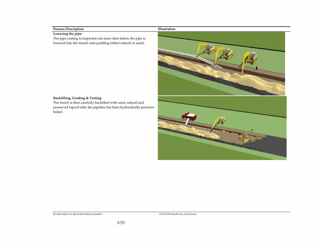
Process Description Illustration
Lowering the pipe:
The pipe coating is inspected one more time before the pipe is
lowered into the trench onto padding (sifted subsoil or sand).
Backfilling, Grading & Testing:
The trench is then carefully backfilled with sand, subsoil and
preserved topsoil after the pipeline has been hydraulically pressure-
tested.
ENVIRONMENTAL RESOURCES MANAGEMENT CCGT POWER PLANT, SALDANHA
3-54
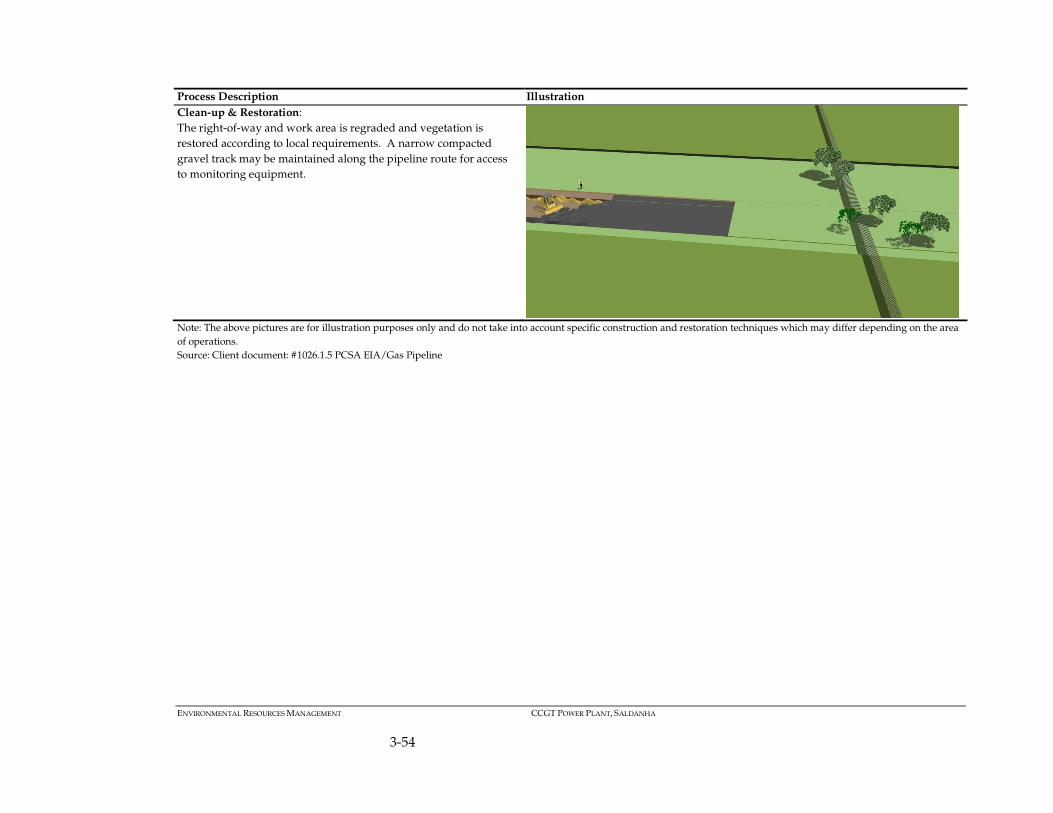
Process Description Illustration
Clean-up & Restoration:
The right-of-way and work area is regraded and vegetation is
restored according to local requirements. A narrow compacted
gravel track may be maintained along the pipeline route for access
to monitoring equipment.
Note: The above pictures are for illustration purposes only and do not take into account specific construction and restoration techniques which may differ depending on the area
of operations.
Source: Client document: #1026.1.5 PCSA EIA/Gas Pipeline
ENVIRONMENTAL RESOURCES MANAGEMENT CCGT POWER PLANT, SALDANHA
3-55
Welding of the pipeline requires electric power. Power for the welding of the
gas pipeline sections will be provided by a mobile diesel generator deployed
to the pipeline construction site. The diesel will be supplied by mobile tankers
on a daily basis. The interred power cable will eventually serve to operate
seawater pumping and filtration plant at the coastline and located close to the
“pigging” send-out station.
3.5.3 Operational Phase
Power Plant
The power plant will be operated on a 24 hour, 7 days a week basis. The
number of workers on site during operations will be about 107 operational
employees and up to 70 part-time employees. These will include plant
management and maintenance staff, skilled mechanical and electrical
technicians, drivers, medical, quality control, and cleaning staff and a number
of experienced plant operators who will operate and maintain the plant, and
who are expected to be a mix of expatriate and local staff.
During commercial operations there will be some traffic bringing supplies and
spares to the power plant. This will increase during shutdowns and periods of
major maintenance.
Maintenance activities will be undertaken by an Operations and Maintenance
(O&M) contractor.
Water requirements
Water requirements during the operational phase are estimated as follows:
• Combined Cycle circuit, replacement feed water: 1 500 m3/y
• Potable water : 200 m3/y
• Water for ablutions during construction 25 m3/day: 1 250 m3/y
• Vacuum system and steam seal evaporative water loss: 500 m3/y
• Sundry cooling system evaporative losses: 250 m3/y
• Water/glycol cooling circuit losses: 1 500 m3/y
• Other evaporative losses PV system washing):1,500 m3/y Water will be
produced by at least two methods:
o Harvesting of rain water climate change dependent: 5 000 m3/y
o Desalination of sea water, 20 - 45 m3/day, potable, up to
14 000 m3/y. Sea-water to be pumped up to plant along gas
servitude. This intended to be a ZLD (zero liquid discharge)
process.
o A third patented process currently being assessed: Recovery by
vapour condensation in gas turbine exhaust.

ENVIRONMENTAL RESOURCES MANAGEMENT CCGT POWER PLANT, SALDANHA
3-56
It has been estimated that a provision of 25 000 m3/year of water would be
sufficient for operation of Phase 1 and Phase 2 of the power plant, this water
would be sourced as follows:
• Trucking from local farms during the construction phase;
• Collection of annual precipitation in 5 x 2000m3 storage tanks;
• A Reverse Osmosis plant on site using sea water that will be pumped
up from the coast along the gas pipeline servitude. The RO process will
be a zero discharge process; and
• Water recovery by condensation from the gas turbine exhaust.
Water during construction will be required for the following activities:
• Off-site dust control: Post treatment recycled water will be used for dust
control on unsurfaced roads where required during high traffic periods
and during construction. Estimated temporary provision of 5,000 m3 per
annum in 2017 and 2018.
• Domestic purposes by on site workers: Maximum water usage during
peak construction period (600 site personnel) is estimated to be 60 m3/day.
This peak requirement is estimated to be needed for approximately 2 years
– 2017 and/ 2019.
• Construction and on-site dust control: Water is required for the
manufacture of concrete during construction. The power plant will require
approximately 80,000 – 90,000 m3 of concrete for foundations, road works,
hard standing and other site works. Estimated temporary provision of
5,800 m3 per annum - 2017 and/ 2019.
Water during operation of Phase 1 and Phase 2 will be required for the
following activities:
Motive steam for the combined cycle (1): Estimated annual provision 1500 m3.
• Annual Cooling water for condensation of steam from steam turbine seals
and vacuum plant seals: Estimated annual provision of 500 m3 (Phase 1
and Phase 2).
• Cooling of lubrication oil for gas turbine, alternators and steam turbine
generator, gas compressor air: Estimated annual provision of 500 m3per
year.
• As water/glycol for combustion air inlet cooling: A cooled water closed-
loop is used to cool down the inlet combustion air to as close to 15 °C as
possible. Estimated annual provision of 1500 m3 per year.
(1) The Benson boiler does not consume water, in that there is no water discharge to out of battery limits, the quantity
indicated here is a provision over and above what may be used for startup

ENVIRONMENTAL RESOURCES MANAGEMENT CCGT POWER PLANT, SALDANHA
3-57
• Make-up water for treated water replacement in event of any boiler blow-
down requirement: Estimated annual provision of 1000 m3 per year.
• Fire abatement: Estimated storage provision of 3000 m3.
Table 3.17 Summary Total Water Usage excluding Fire Contingency
Project Stage Year 1 Year 2 Year 3 Year 4 Operation Phase 1
and 2
Year 5
Operation Phase 1 and 2
Construction
(m3)
20,000 20,500 16,500 0 16,500
Operation (m3) 3,000 3,000 5,000 12,000 12,000
This will be confirmed as the design details for the plant are progressed
through the BFS.
Utilities and materials
Table 3.18 presents a preliminary list of the incoming utilities and materials to
the power plant site.
Table 3.18 Preliminary list of incoming utilities and materials
Utility Notes
Natural Gas Brought in by pipeline
LPG Brought in by truck
Sea water Brought in by pipeline
Process Materials Brought in by truck
Hydrogen Brought in cylinders for generator cooling
Ethylene Glycol Brought in in steel drums for cooling water treatment
& process chemicals
Ammonia Brought in drums, by truck
Water treatment & process chemicals
Ammonia Brought in drums, by truck
Sulphuric acid Brought in drums, by truck
Demineralizing resins Brought in drums, by truck
Carbon dioxide, Gas cylinders, brought in by truck
Sewage treatment chemicals (
Organic)
Workshop consumables Fluxes, welding rods, gaskets, etc.
Maintenance consumables
Paint Brought in metal cans
Lubricating greases Brought in metal cans
Fire-extinguishing foam Standard gas/foam cylinders
Canteen food Brought in by truck
Office consumables
Construction Aggregates Sand, gravel, cement, brought in by truck

ENVIRONMENTAL RESOURCES MANAGEMENT CCGT POWER PLANT, SALDANHA
3-58
Table 3.19 provides a preliminary list of the outgoing utilities and materials
form the power plant.
Table 3.19 Preliminary list of outgoing utilities and materials
Outgoing Utility / Material Estimated Quantity
Electricity max. 34,800 MWhe/day
Potable water max. 30,000 l/d
Waste lube oil max. 15 tons/year
Solid desalination salt residue: approximately 900 kg/day
Canteen waste -food products 100 kgs/day
Dewatered solids from waste water treatment max. 50 Kg/day
Spent anti-fire agent cylinders
Waste, non-oil maintenance materials est. max. 5 tons/y
Spent consumables and cleaning products. est. max. 5 tons/y
Services
The following services will be provided by the project itself, managed by a
services department on site or contracted to a third party:
• Electricity;
• Gas;
• Raw water treatment, including filtration RO and demineralisation;
• Water recovery from waste water;
• Sewage treatment;
• Boiler feed water;
• Boiler blow-down recovery;
• Condensate;
• Fire water;
• Cooling water;
• Hydrogen generator cooling system;
• CO2 fire abatement system; and
• Compressed air.
Emissions
Emissions from the plant will result from a number of sources and depend on
the fuel used to generate power. It should be noted that propane will only be
used for emergency black starts.
Phase 1
The likely emissions, at maximum continuous rating (MCR)(1), that can be
expected during Phase 1 of the Project are shown in Table 3.1.
(1) Maximum continuous rating (MCR) is defined as the maximum output (MW) that an electric power generating station
is capable of producing continuously under normal conditions over a year.

ENVIRONMENTAL RESOURCES MANAGEMENT CCGT POWER PLANT, SALDANHA
3-59
Table 3.20 Estimated Emissions from the Project – Phase 1**
Emitter UNIT
NUMBER
Capacity
MWe at
MCR
Stack Flow
Kgs/sec
SOx CO
Mg/Nm3
NOx
Mg/Nm3
CO2
Kg/hr
Trent 60 DLE * T1 48 152 46 50 27.161
Trent 60 DLE * T2 48 152 46 50 27.161
Trent 60 DLE * T3 48 152 46 50 27.161
Trent 60 DLE * T4 48 152 46 50 27.161
Trent 60 DLE * T5 48 152 46 50 27.161
*Open Cycle at site conditions 25°C, 20m, 65%RH
#Open cycle, nominal rating
**The 6th Trent 60 DLE unit is not included in this table as it is redundant.
Table 3.21 Exhaust Gas Emission Rate and Temperature
Emitter UNIT
NUMBER
Stack Height Rate
Kg/sec
Temperatur
e
°C
Trent 60 DLE * T1 through T6 40 m 152 439
*Open Cycle at site conditions 25°C, 20m, 65%RH
#Open cycle, nominal rating
Phase 2
The likely emissions, at maximum continuous rating (MCR)(1), that can be
expected during Phase 2 of the project are shown in Table 3.1.
Table 3.22 Estimated Emissions from the Project – Phase 2
Emitter UNIT
NUMBER
Capacity
MWe at
MCR
Stack Flow
Kgs/sec
SOx CO
Mg/Nm3
NOx
Mg/Nm3
CO2
Kg/hr
SCC5-4000F 1S UNIT 2 435 680 0 35 <20 152,200
SCC5-4000F 1S UNIT 3 435 680 0 35 <20 152,200
SCC5-4000F 1S UNIT 1 435 680 0 35 <20 152,200
*Combined Cycle at site conditions 25°C, 20m, 65%RH
Table 3.23 Exhaust Gas Emission Rate and Temperature
Emitter UNIT
NUMBER
Stack Height Rate
Kg/sec
Temperature
°C
SCC5-4000F 1S UNIT 2 60 m 675 90 - 110
SCC5-4000F 1S UNIT 3 60 m 675 90 - 110
SCC5-4000F 1S UNIT 1 60 m 675 90 - 110
*Combined Cycle
(1) Maximum continuous rating (MCR) is defined as the maximum output (MW) that an electric power generating station
is capable of producing continuously under normal conditions over a year.

ENVIRONMENTAL RESOURCES MANAGEMENT CCGT POWER PLANT, SALDANHA
3-60
Waste Generation
Construction wastes will comprise general domestic waste including sanitary
and food waste, office waste, organic material, small volumes of wastes
arising from mobile plant, chiefly waste lubricating oil and packing materials
(e.g. crates).
Operational phase waste streams are as follows:
• Used generator and turbine lube oil (collected in a tank on site and then
removed off-site in drums for controlled disposal);
• Occasional oily sludge recovered from on-site collected road surface or
hard-standing surface water treatment;
• Spent gas turbine fabric air filter cartridges;
• Spent gas turbine lube-oil filter cartridges;
• Dried powdered sludge from sewerage treatment and ablution and
canteen washing areas;
• Spent office consumables (paper, printer cartridges etc.);
• Organic waste food from canteen operations and organic cooking oil waste
from canteen operations;
• Glass waste and metal can waste from canteen operations;
• Scrap steel and copper from irreparable mechanical equipment;
• Scrap plastics from equipment packaging;
• Dry solids (mineral salts) recovered from zero discharge reverse osmosis
process;
• Spent resins from water demineralisation;
• Waste solvents and grease from workshop equipment cleaning operations;
and
• Spent laboratory chemicals from water testing and water treatment.
No waste material will remain on site.
Potentially hazardous chemicals will be neutralised (if acidic) and then
separately hermetically packed and labelled prior to disposal.

ENVIRONMENTAL RESOURCES MANAGEMENT CCGT POWER PLANT, SALDANHA
3-61
The disposal of waste will be carried out in accordance with the relevant
legislation. All solid wastes generated will be disposed of at licensed landfill
sites, for general and/ or hazardous waste streams.
The combined cycle circuit will generate steam through a Benson type boiler.
This is a drum-less boiler that although there is a much diminished blow-
down, compared to a conventional drum boiler, the blowdown water is
recuperated and re-used.
Pipeline
Pipeline operation, marking and monitoring
The position and location of the buried gas pipeline will be indicated above-
ground by special marker beacons laid above the pipeline in line-of-sight of
each other along the pipeline servitude route (Figure 3.30). The markers will be
able to collect and transmit essential pipeline information by means of
telemetry, as described below.
Figure 3.30 Example of a marker indicating pipeline below ground
The pipeline is expected to operate continuously, for 8760 hours per year, only
the flow rate will vary. The pipeline operating conditions are listed in Table
3.24.
Table 3.24 Pipeline operating conditions
Parameter Operating Condition
Gas temperature 20 C ( insulated pipeline)
Flow rate 25 – 65 kg/sec
Working pressure max. 90 barg, min 45 barg, average 67 barg

ENVIRONMENTAL RESOURCES MANAGEMENT CCGT POWER PLANT, SALDANHA
3-62
Parameter Operating Condition
Pipeline maximum allowable stress 78,500 barg (7854 Mpa)
Solar-powered data collection nodes along the pipeline route will constantly
collect and retransmit pipeline operational statistics, cathodic or anodic
protection performance or alarms to the power plant’s control room. Pipeline
gas flow interruption during maintenance interventions could also interrupt
power generation, thus sophisticated measures will be put in place to pre-
empt the need to shut off gas flow at any time.
Several leak detection technologies are available and will be incorporated by
EPC contractor. Those currently available are as follows:
• In – pipeline instrumentation based on acoustic sensors
• In – pipeline condition assessment with pigging.
• Above-ground air sampling along the pipeline route (Unmanned Aerial
Vehicle UAV or manually operated);
• Detection of tracer chemical introduced into the gas pipeline and detected
above ground;
• Automatic solar-powered leak detection sensors capable to trigger control
room alarm;
• Radio/WiFi instrumentation information transmitted to control
room/pipeline operator; and
• Pipeline monitoring data collected regularly by plant operated security
Unmanned Aerial Vehicle (UAV).
Emergency shut-down and emergency response
Whilst the emphasis for pipeline operation is continuous operability, the
pipeline can be shut down in case of emergency. The pipeline can be isolated
at three locations, namely at the LNG degasifier that feeds the pipeline with
gas, and closing the two pipeline isolation valves either from the plant control
room or manually. These valves are located at the despatch pigging station at
the beginning of the land-based pipeline. The pipeline will be allowed to
depressurise via a small gas flare at the pig-receiving station and residual gas
will be expelled by a spherical ‘pig’.
The prime risk associated with the pipeline emanates from undetected gas
leaks from:
• Pipeline or valve rupture due to excessive pressure and failed welds;
• Pipeline or valve rupture due to sub-surface geological or subsoil
instability; and
• Pipeline or valve rupture plus break-down of all leak detection and alarm
systems.
The impact of an undetected gas leak can result in:

ENVIRONMENTAL RESOURCES MANAGEMENT CCGT POWER PLANT, SALDANHA
3-63
• Fire, or in the worst case, a high energy explosion of the ruptured gas
pipeline;
• Setting alight surrounding flora and any habitation; and
• Hydrocarbon contamination of the natural environment.
Emergency response measures in the event of a sudden catastrophic rupture
of the pipeline will be put in place, including:
• Reliable and immediate shut-off capability of all valves along the pipe-line
route, including sea-water feed-valve and mid-route water isolation valve.
Where the automatic valve actuators have been incapacitated, the pipeline
will be isolated manually by a trained rapid response team;
• The underground power-cable will have been isolated automatically
through loss of gas pipeline pressure;
• Immediate shut-down of the regasification facility;
• Immediate start-up of fresh water fire pump feeding the water pipeline;
• Rapid response fire response team;
• Shutting off all roads that have a pipeline crossing;
• Controlled shutdown of the power plant;
• Dissemination of information and knowledge of the pipeline location and
hazards to local fire authorities; and
• Being a Class 1 location installation, personnel or habitation or buildings
close to the pipeline will be minimal/non-existent. Nevertheless the plant
medical team and fire response team will have access along the pipeline
route.
3.5.4 Decommissioning Phase
Decommissioning is the term used to describe all stages involved in the
closure and rehabilitation of the power plant site. The process can generally be
categorised into the three key phases as follows:
• Pre decommissioning activities: includes the detailed planning
(development of a Decommissioning Plan, Site Closure and Restoration
Plan) and approval facilities;
• Decommissioning activities: removal of all infrastructure (including the
cables and pylons for the connection to the existing transmission line).
Machinery, steel and dismantled materials will be recycled where possible
and disposed of at licensed disposal sites; and
• Post decommissioning activities: site survey, close out report and field
monitoring as necessary.
It is likely that the project facilities will only be decommissioned once the gas
supply has been exhausted, when it is no longer economical to continue
operation, or the plant is rendered redundant or is no longer required for
ENVIRONMENTAL RESOURCES MANAGEMENT CCGT POWER PLANT, SALDANHA
3-64
various reasons, or is unsafe to operate. As the development process of the site
is yet to fully begin, detailed decommissioning plans have not yet been
formulated; however, the initial plant life will be designed for 25 to 30 years.
Upgrades during the life of the plant can increase the design life to 50 years.
A Decommissioning Plan will only be developed during the latter stages of
the production life of the facilities. The assessment of the significance of the
environmental and social impacts associated with decommissioning will need
to be conducted once the Decommissioning Plan is finalised.
3.6 ASSUMPTIONS
The following assumptions have been made with respect to the project
description chapter:
1. There will be a permanent easement above the pipeline of 3m either side
of the centre line;
2. There will be a temporary Right of Way (RoW) of 36m (18m either side of
the centre line) of the pipeline during the construction phase;
3. There will be a permanent 30m servitude for the feeder 132kV power line
from the power plant to the ArcelorMittal Steel Works (15m either side if
the centre line)
4. The site access arrangements illustrated in this section are conceptual and
have been engineered and costed as they are represented using generic
data from various contractors with past experience. Special requirements
that may be requested in addition to the to-date assumptions and findings
have not been taken into account in this report.