3 - massachusetts institute of...
TRANSCRIPT
, q ! . . (; .'. ! , ~ .') I' <3 \:
0 0 0 D A R D ,PACE CLlQHT CI?NTmR
Greenbelt, Maryland Phone (301) 982-4955.56-57 After Hours 474-9000
N A T I O N A L ACBONAUTIC. A N 0 SPACm A D M I N I S T R A T I O N
THE MANNED SPACE F L I G H T NETWORK FOR APOLLO
A u g u s t , 1968
MSFN - THE APOLLO GROUND NETWORK
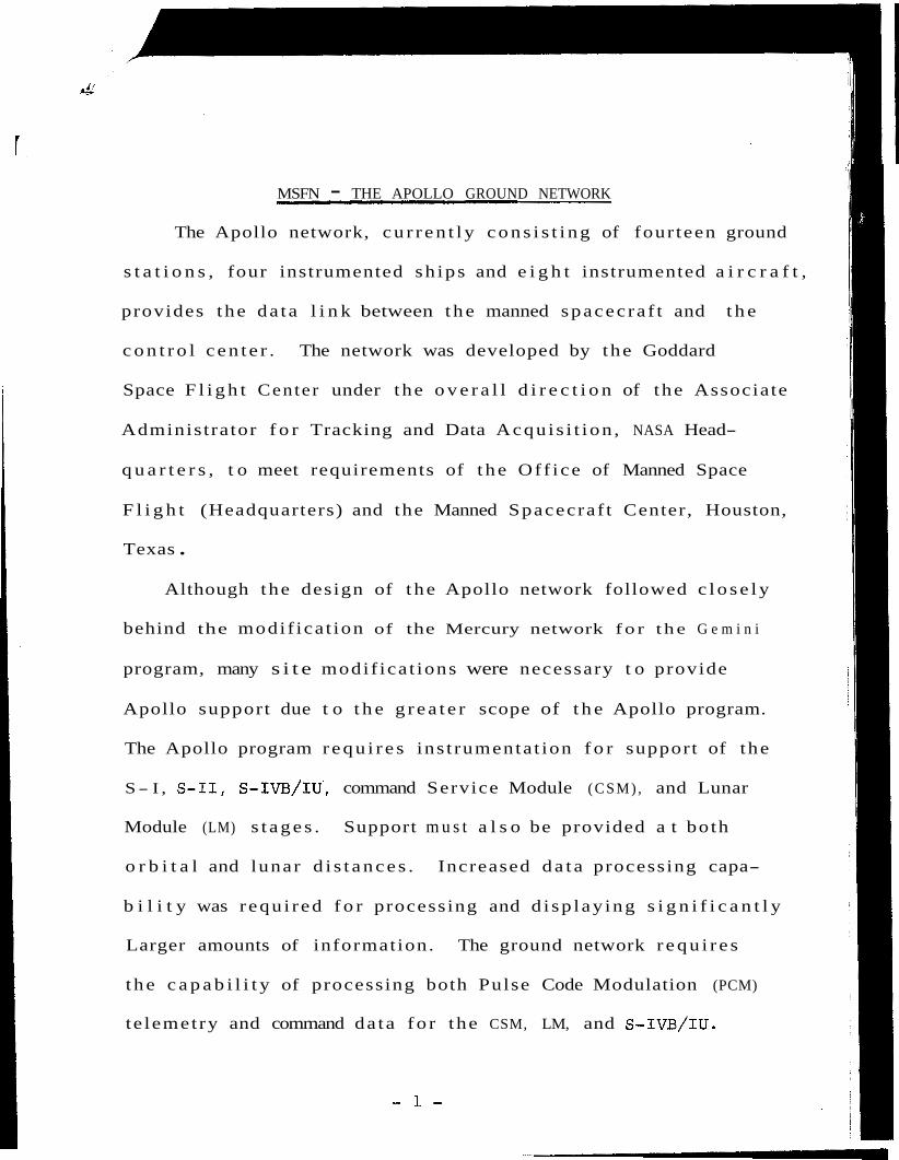
The Apollo network, c u r r e n t l y c o n s i s t i n g of four teen ground
s t a t i o n s , four instrumented sh ips and e i g h t instrumented a i r c r a f t ,
provides the da ta l i n k between t h e manned spacec ra f t and t h e
c o n t r o l c e n t e r . The network was developed by the Goddard
Space F l i g h t Center under the o v e r a l l d i r e c t i o n of the Associate
Adminis trator f o r Tracking and Data Acqu i s i t ion , NASA Head-
q u a r t e r s , t o meet requirements of t h e Of f i ce of Manned Space
F l i g h t (Headquarters) and the Manned Spacecraf t Center, Houston,
Texas .
Although the design of t h e Apollo network followed c l o s e l y
behind the modif ica t ion of the Mercury network f o r t h e G e m i n i
program, many s i t e modif ica t ions were necessary t o provide
Apollo support due t o t h e g r e a t e r scope of t h e Apollo program.
The Apollo program r e q u i r e s ins t rumenta t ion f o r support of the
S- I , S-11, S-IVB/IU' , command Service Module (CSM) , and Lunar
Module (LM) s t a g e s . Support m u s t a l s o be provided a t both
o r b i t a l and lunar d i s t a n c e s . Increased d a t a processing capa-
b i l i t y was r equ i red f o r processing and d i sp lay ing s i g n i f i c a n t l y
Larger amounts of information. The ground network r e q u i r e s
t h e c a p a b i l i t y of processing both Pulse Code Modulation (PCM)
te lemetry and command da ta f o r the CSM, LM, and S - I V B / I U .
- 1 -

M I S S I O N CONTROL AND TRACKING
I n support of Apollo, a s i n Gemini, the NASA Goddard
Space F l i g h t Center i s respons ib le f o r the o v e r a l l ope ra t ion
of t h e NASA Manned Space F l i g h t Network ( M S F N ) . For Apollo
t h e r e w i l l be four t een land s t a t i o n s and four sh ips providing
one or more of the following r e a l time funct ions f o r f l i g h t
c o n t r o l purposes:
1. te lemetry r ecep t ion and decommuntation,
2 . t r a c k i n g ,
3 . commanding, and
4 . voice communications with t h e s p a c e c r a f t .
I n a d d i t i o n t o the MSFN land s t a t i o n s and sh ips t h e r e
a r e seve ra l network a i r c r a f t i n each of the prime recovery
a r e a s t o provide a voice r e l a y between t h e s p a c e c r a f t and
MSFN during t h e landing phase.
M I S S I O N CONTROL CENTER - HOUSTON (MCC-H)
The Mission Control Center a t the Manned Spacec ra f t
Center i n Houston i s t h e f o c a l p o i n t fo r a l l Apollo f l i g h t
c o n t r o l a c t i v i t i e s . I n performing the c o n t r o l f u n c t i o n , and
dstermining t h e progress of the f l i g h t , t h e MCC-H r e c e i v e s
t r ack ing and te lemetry da ta from t h e MSFN. This da ta i s
processed through the MCC-H Real Time Computer Complex
(RTCC) and used t o d r ive d i sp lays f o r the f l i g h t
- 2 -
c o n t r o l l e r s and engineers i n t h e Mission Operations Control
Room and S t a f f Support rooms. I n a d d i t i o n t o r ece iv ing da ta
from t h e t r a c k i n g and te lemetry systems, the MCC-H f l i g h t
c o n t r o l l e r s a r e able t o ob ta in ve rba l information concerning
the f l i g h t by t a l k i n g t o the a s t r o n a u t s v ia the voice r e l a y
f a c i l i t i e s a t t h e s i t e s . Real time s p a c e c r a f t t e l e v i s i o n w i l l
be rece ived a t t h e MCC-H from the network's MELA ( M e r r i t t
I s land Launch Area) s i t e a t Cape Kennedyc& Corpus C h r i s t i , Tex.
NETWORK SUPPORT TEAM
The team mans the var ious communications p o s i t i o n s a t
the Manned Space F l i g h t Operations Center (MSFNOC). The NST
i s comprised of t e c h n i c a l and opera t iona l personnel r equ i red
by the Network D i r e c t o r , Network Operat ions Manager (NOM) and
the Network Con t ro l l e r ( N C ) t o ope ra te t h e MSFNOC, a ss i s t
i n c o n t r o l l i n g the MSFN, and coordina t ing i t s a c t i v i t i e s .
The NST i s respons ib le t o ensure tha t a l l MSFN communi-
c a t i o n s i s coordinated i n a bus iness- l ike manner. The team
provides the Network Operations Manager and/or N e t w o r k
Con t ro l l e r w i t h the necessary t e c h n i c a l a s s i s t a n c e requ i red
t o e f f e c t i v e l y c o n t r o l and coordina te the MSFN and i t s a c t i -
v i t i e s . The NST i s a l s o r e spons ib le f o r communicating w i t h
e x t e r n a l f a c i l i t i e s f o r a s s i s t a n c e no t a v a i l a b l e in-house.
- 3 -
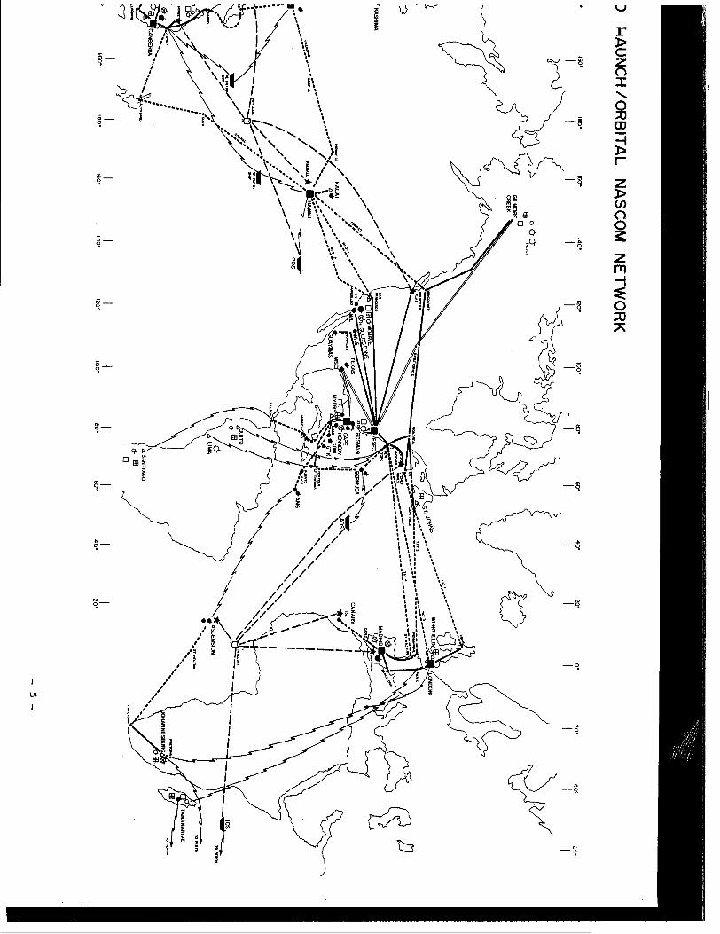
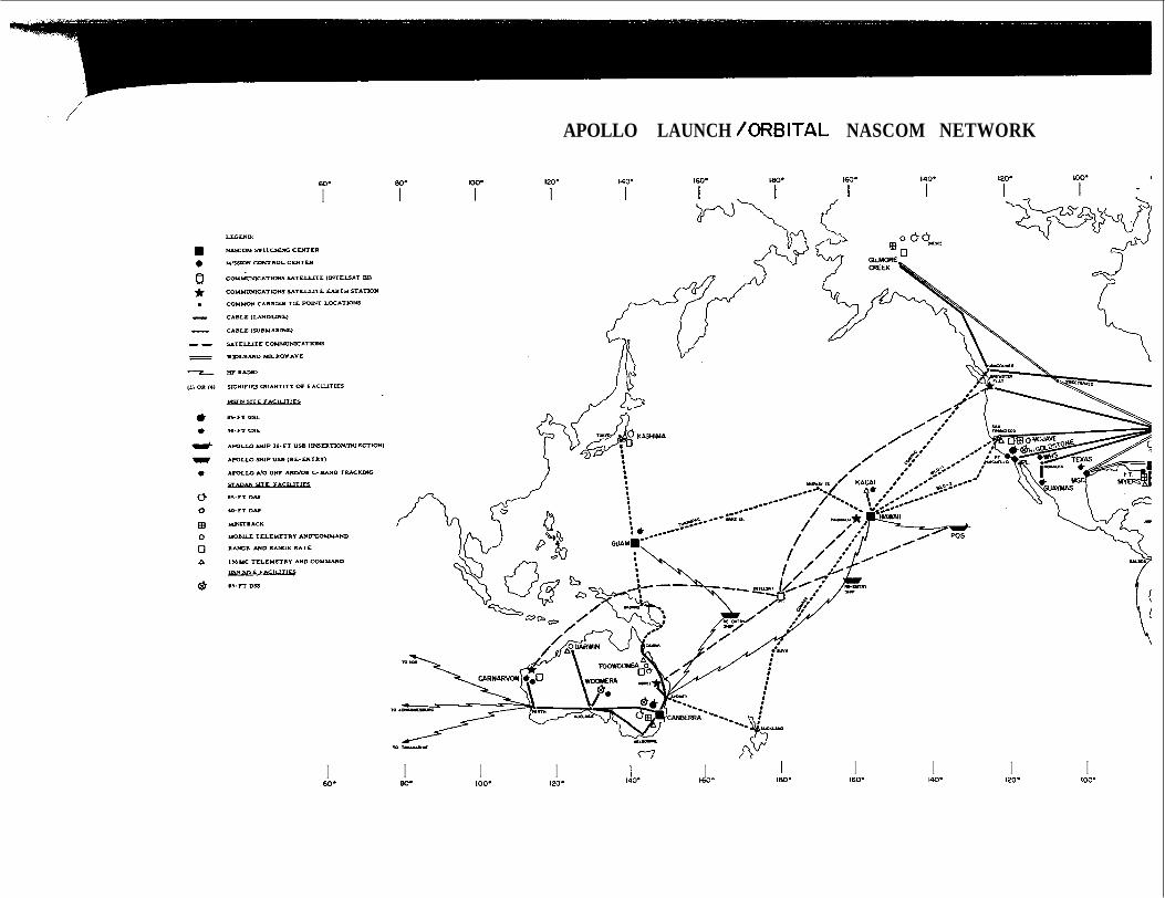
NASCOM NETWORK FACILITIES
The NASCOM network c o n s i s t s of s e v e r a l systems of d i v e r s e l y
routed communications channels l ea sed from var ious domestic and
fo re ign communications common carr iers on a worldwide basis .
These channels a r e l eased i n l a n d l i n e s , submarine cables, and
communications s a t e l l i t e s wherever a v a i l a b l e , and i n hf r a d i o
. f a c i l i t i e s where necessary t o provide t he access l i n k s .
The system c o n s i s t s of bo th narrow and wideband channels ,
and some TV channels . Included a r e a v a r i e t y of t e l eg raph , vo ice ,
and data systems ( d i g i t a l and analog) wi th a wide range of d i g i t a l
d a t a r a t e s . Wideband and TV systems do no t p r e s e n t l y extend
overseas . To t h e e x t e n t p o s s i b l e , channels are d i v e r s i f i e d on
r o u t e s a v a i l a b l e t o minimize system degradat ion i n t h e event of
communications ou tages , and i n i n s t a n c e s where necessary , a l t e r-
n a t e rou te s or redundancy i s provided t o meet r e l i a b i l i t y c r i t e r i a
f o r c r i t i c a l mission opera t ions .
A primary switching center and in te rmedia te switching and
c o n t r o l p o i n t s are e s t a b l i s h e d t o provide c e n t r a l i z e d f a c i l i t y
and t echn ica l c o n t r o l , and switching opera t ions under d i r e c t
NASA c o n t r o l . The primary switching cen te r i s a t GSFC, Greenbel t ,
Maryland, and in te rmedia te switching c e n t e r s are loca t ed a t
Canberra, Madrid, London, Honolulu, Guam, and Cape Kennedy.
Attached map i l l u s t r a t e s approximate geographic l o c a t i o n s and
i d e n t ' i f i e s t h e type of long-haul common carr ier f a c i l i t i e s ; impor-
t a n t cable and communications s a t e l l i t e t i e p o i n t s u s e d on the
major p o r t i o n of t h e NASCOM network. - 4 -
r
60. I
APOLLO LAUNCH /ORBITAL NASCOM NETWORK
I 60-
I I I I I 80. 100. 120- 140. 160-
I 160.
I 1 4 0 -
I I 120- 100-
For a t y p i c a l Apollo launch, Cape Kennedy is connected
d i r e c t l y t o t he Mission Control C e n t e r , Houston, by NASCOM's
Apollo Launch Data System, a combination of da ta ga ther ing and
t ransmiss ion systems designed t o handle launch d a t a exc lus ive ly .
A high speed data (2400 b i t pe r second) l i n e connects t he Cape
t o Goddard. A t Goddard the t ransmiss ion r a t e i s increased
t o 40 ,800 per second r a t e
from t h e r e t o Houston.
Once launch i s achieved, a l l network and t r ack ing da ta i s
d i r e c t e d t o the Mission Control Center , Houston, through
Goddard. Upon o r b i t a l i n s e r t i o n , t r ack ing r e s p o n s i b i l i t y i s
t r a n s f e r r e d between the v a r i o u s s t a t i o n s as the spacec ra f t
c i r c l e s the ear th .
There are t w o Apollo ( I n t e l s a t ) communications s a t e l l i t e s .
One i s pos i t i oned over t he A t l a n t i c Ocean i n an e q u a t o r i a l or-
b i t varying approximately s i x degrees between North and South
l a t i t u d e and s i x deyrees West longi tude . The A t l a n t i c satel-
l i t e w i l l s e r v i c e t he Apol.10 Indian Ocean s h i p , Ascension
I s l and USB s t a t i o n , the A t l a n t i c Ocean s h i p , and the Canary
I s land s i t e .
Only two of these four s t a t i o n s w i l l be t r a n s m i t t i n g in fo r-
mation back t o Goddard a t any one time; however, a l l four
s t a t i o n s w i l l have the c a p a b i l i t y of rece iv ing information a t
- 6 -

- l -
a l l times. During launch, f o r example, t he NASCOM connects
wi th t he Apollo A t l a n t i c Ocean sh ip o r w i l l s h i f t t o t h e
Ascension I s l and USB s i t e . For the nex t r evo lu t ion , Canary
I s l a n d and the Indian Ocean sh ip , o r some suitable combination
i s arranged t o achieve t h e best coverage. During these even t s ,
realtime communications (no de lay) switching i s r equ i r ed .
The second Apollo COMSAT i s loca t ed a t approximately 170
degrees east longi tude over t he Mid-Pacific near t he i n t e r -
s e c t i o n of t h e equator and t h e i n t e r n a t i o n a l d a t e l i n e . I t
w i l l s e rv i ce t h e Carnarvon, West Aus t r a l i an USB s i te and t h e
P a c i f i c Ocean sh ip . Both of t hese s t a t i o n s w i l l be able t o
t r ansmi t simultaneously through t h e s a t e l l i t e t o Houston v i a
Brewster F l a t , Washington, and the Goddard Space F l&ght Center .
Thirty- nine (UNIVAC 642B) Computers, key components i n
t h e globe-encompassing NASCOM network, accep t records, and
- i n c r i t i c a l cases - t r a n s m i t s d a t a o r i g i n a t i n g from the
spacec ra f t ("down" d a t a ) , computes and t r ansmi t s commands t o
t h e Apollo capsule ("up" data) . A g r e a t many more p e r i p h e r a l devices - magnetic t ape
u n i t s , input/output conso les , Te le typewr i te rs , keyboard u n i t s ,
e t c . - a r e included i n t he "NASCOM" (NASA Communications N e t -
work) .
- 8 -
I

f ' COMPUTERS AT WORK
A t fraction-of-a-second i n t e r v a l s , t h e network 's d i g i t a l
d a t a processing systems, with NASA's Manned Spacecraf t Center
a t Houston, Texas, as the foca l p o i n t , " t a l k " t o each o the r
or t o the a s t r o n a u t s i n rea l- t ime (without no t i ceab le time l o s s ) .
High speed computers a t t h e remote s i t e s ( t r ack ing sh ips included)
i s s u e commands o r ''up" da ta on such mat ters a s c o n t r o l of
cabin pressure , o r b i t a l guidance commands, o r "go-no-go"
i n d i c a t i o n s t o perform c e r t a i n func t ions .
I n the case of information o r i g i n a t i n g from Houston, the
computers refer t o t h e i r pre-programmed information f o r v a l i d i t y
before t r a n s m i t t i n g t h e requi red da ta t o the capsule .
Such "up" information i s communicated by u l t ra- high
frequency radio a t a r a t e of about * 2 , 0 0 0 bi t s per second.
communication between remote ground s i t e s , v i a high-speed
communications l i n k s , occurs a t about the same r a t e . Houston
reads information from these ground s i t e s a t a r a t e of 2 , 0 0 0
b i t s per second, a s well a s from remote s i t e s a t about 100
words per minute.
The computer systems perform many o ther func t ions , inc luding:
.Assuring t h e q u a l i t y of t h e t ransmission l i n e s b y
* Four b i t s equal one d i g i t (Binary 1- 9 ) . According t o pre-
arranged da ta format , any v a r i a t i o n of 600 d i g i t s / s e c of
information may be moved.
- 9 -
/ c o n t i n u a l l y exe rc i s ing da t a pa ths .
*Veri fying accuracy of t h e messages by redundant
( r e p e t i t i v e ) ope ra t ions .
'Constantly updating t h e f l i g h t s t a t u s .
I n t h e case of "down" d a t a , sensors b u i l t i n t o t h e space-
c r a f t con t inua l ly sample cabin temperature, a l t i t u d e of t he
capsu le , or such phys i ca l t r a i t s of t h e a s t r o n a u t s a s h e a r t
beat and r e s p i r a t i o n . Such da t a i s t ransmi t ted t o t h e ground
s t a t i o n s a t a ra te of 5 1 . 2 k i l o b i t s ( 1 2 , 8 0 0 b ina ry d i g i t s )
pe r second.
The computers w i l l then:
'Detect and select changes o r d e v i a t i o n s , compare wi th
t h e i r s t o r e d programs, and generate t h e problem a r e a s
o r p e r t i n e n t data t o t he f l i g h t c o n t r o l l e r s .
'Provide con t inua l d i s p l a y t o cognizant personnel .
'Assemble ou tpu t da t a i n proper formats.
-Log da t a on magnetic t ape f o r rep lay .
-Provide s to rage for "on- cal l" d i s p l a y for t he f l i g h t
c o n t r o l l e r s .
'Keep time.
Twelve land s t a t i o n s a r e o u t f i t t e d wi th computer systems
t o r e l a y te lemetry and command information between Houston and
Apollo spacec ra f t : Canberra, A u s t r a l i a : Guam; K a u a i , H a w a i i ;
Goldstone, Ca l i fo rn i a : Corpus C h r i s t i e , Texas; Cape Kennedy:
Grand Bahama I s l and : Bermuda; Madrid, Spain: Antigua; Grand
Canary I s l a n d ; and Ascension I s l a n d . - 10 -

A t var ious stages both USB and VHF te lemetry l i n k s
a r e r equ i r ed . To provide support fo r t he Apollo program,
many s i g n i f i c a n t changes have been made t o the network
systems:
1. Unified S-Band system combines the func t ions of
a c q u i s i t i o n , t e lemet ry , command, vo ice , and
t r a c k i n g on one r a d i o l i n k . The u s e of t h i s
system inc reases t he da t a process ing t a s k , b u t
reduces the number of requi red antenna mounts,
t r a n s m i t t e r s ; r e c e i v e r s , e t c .
2 . S tored program PCM te lemet ry decommutators were
i n s t a l l e d t o provide increased da ta handl ing
c a p a b i l i t y and f l e x i b i l i t y .
3. Computer-driven (a lpha numeric) d i s p l a y s were
s e l e c t e d t o provide a g r e a t e r ope ra t iona l and
decision-making c a p a b i l i t y t o f l i g h t d i r e c t o r s .
This system permits the d i s p l a y of p r i n t e d in fo r-
mation and c h a r t s of real-time da t a on a cathode
r ay tube.
- 11 -

/
4. A genera l purpose da ta processing system u t i l i z i n g
Univac 6 4 2 B computers i s provided a t each s i t e t o
d r i v e d i s p l a y s , process t e l emet ry , command and
t e l e t y p e da ta and t o s e l e c t and format d a t a f o r
t ransmiss ion t o the Houston, Texas c o n t r o l c e n t e r .
This system processes and s t o r e s command da ta
rece ived from the c o n t r o l cen te r f o r delayed
t ransmiss ion t o the s p a c e c r a f t . The da ta processing
system a t each s i t e i s connected t o the Houston ten-
t e r by high speed da ta c i r c u i t s . This f e a t u r e
provides the con t ro l cen te r with t h e c a p a b i l i t y
of remotely changing da ta parameters being
t r ansmi t t ed t o the c o n t r o l cen te r and t h e capa-
b i l i t y of remotely up- linking d a t a t o the s p a c e c r a f t .
5 . Other miscellaneous systems added t o t h e network
f o r Apollo support inc lude: TV moni tors , h igh
speed p r i n t e r s , s t o r e d program PCM s imula to r s ,
VHF p r e d e t e c t i o n ( d i v e r s i t y combining) r e c e i v e r s
and wide band recorde r s .
Maximum f l e x i b i l i t y , through mociularity of des ign , and
h igh r e l i a b i l i t y , through s e l e c t e d systems redundancy and
- 1 2 -
f a
Planned redundancy was provided i n systems design t o
improve r e l i a b i l i t y . Expansion and r a p i d conf igura t ion
c a p a b i l i t i e s were a l so designed i n t o t h e major equipment.
Most modif icat ions t o t h e network due t o d i f f e r e n c e s i n
miss ion p r o f i l e s can be made by sof tware change r a t h e r than
hardware modi f ica t ions . Programmable u n i t s include the
a d a p t e r , and t h e d i sp l ay system. F l e x i b l l l t y o t cleslgn
i n network systems w i l l enable t he network t o support a
g r e a t v a r i e t y of f u t u r e m i s s i o n s . I
- 1 3 -
APOLLO TV SYSTEM
The Apollo t e l e v i s i o n l i n k a s c u r r e n t l y planned w i l l
s e rve a twofold purpose. First , it w i l l permit v i s u a l
observat ion and conf i rmat ion of a s t r o n a u t a c t i v i t i e s by
ground con t ro l : secondly, it w i l l enable selected p o r t i o n s
of t he se t e l e v i s e d a c t i v i t i e s t o be d i s t r i bu t ed t o the
commercial networks for p u b l i c viewing, pending release
approval by NASA.
The t e l e v i s i o n s i g n a l s a r e t r ansmi t t ed from t h e
spacecraft i n the Apollo slow scan format, a r e received
a t the USB s t a t i o n s and then recorded on magnetic t ape .
The M I L A (Merritt I s l and Launch Area) and TEXAS (Corpus
C h r i s t i ) s i tes are equipped wi th slow scan conver te rs ’
t o render it compatible w i t h commercial TV requirements.
The s i g n a l i s then t r ansmi t t ed i n r e a l time t o t h e MCC.
- 14 -

THE APOLLO SHIPS
The Manned Space F l i g h t Network (MSFN) has four
f l o a t i n g s i tes . Cal led the Apollo Ins t rumentat ion Ships
( A I S ) , these s i t es a r e i n t e g r a l p a r t s of t he MSFN, equa l ly
important t o m i s s i o n success , and more dynamically equipped
than some land s t a t i o n s .
The Apollo space veh ic l e w i l l be launched on a launch
azimuth between 72 and 108 degrees from Cape Kennedy.
There i s a p o i n t over t h e e a r t h , f i x e d with r e s p e c t
t o t h e cen te r of t he e a r t h and t h e center of t h e moon, a t
which the s p a c e c r a f t m u s t be i n j e c t e d i n t o i t s t r a j e c t o r y
t o t h e moon. Since t h e e a r t h i s r o t a t i n g on i t s a x i s under
t h i s p o i n t i n space, t h e requi red launch azimuth v a r i e s
w i th t he time of day and month. On any given day, t he
launch window ( t h a t i s , t he time i n t e r v a l dur ing which an
acceptab le launch can be made) should be a t leas t 2-1/2
hours i n l eng th ; t h u s , t he requi red launch azimuth may vary
over a s ec to r bounded roughly by Bermuda on t h e no r th and
Antigua on the south.
- 15 -

After the lower (boos te r ) s t a g e s of t h e Saturn have
burned o u t and dropped o f f , t h e f i rs t powered phase of
t h e S- IVB upper s t age " i n s e r t s " the Apollo i n t o an e a r t h
o r b i t , known as a parking o r b i t , a t approximately 100
miles a l t i t u d e . This " i n s e r t i o n " maneuver i s one of t h e
crucial phases which m u s t be covered by a t r ack ing s t a t i o n ,
and s ince it w i l l occur over t h e broad ocean a r e a between
Bermuda and Antigua, a t r ack ing s h i p i s requ i red t o fill
t h e gap no t covered by e i t h e r of these two land s t a t i o n s .
This sh ip m u s t be a b l e t o t r a c k f o r an i n t e r v a l of a t
l e a s t three minu tes i n order t o determine the s u i t a b i l i t y
of t h e o r b i t f o r t h e l a t e r i n j e c t i o n i n t o t r a n s l u n a r
t r a j e c t o r y .
Three e x i s t i n g T-2 tanker type h u l l s were converted
f o r Apollo s p a c e c r a f t i n s e r t i o n / i n j e c t i o n coverage and one
C-2 v i c t o r y s h i p f o r e a r t h atmosphere re- ent ry . Ins t rumen-
t a t i o n requirements f o r the re- ent ry sh ip a re less demanding
t h a n f o r the i n s e r t i o n / i n j e c t i o n s h i p s , t h e r e f o r e , equip-
ment and o the r comparable items d i f f e r .
Along w i t h surface s t a t i o n s and a i r c r a f t , these ships
- 16 -

w i l l serve a s l i n k s i n t h e Manned Space F l i g h t Network
(MSFN) chain between t h e Apollo s p a c e c r a f t and the Manned.
Space F l i g h t Control Center (MCC-H), Houston, Texas.
These sh ips include Apollo support ins t rumenta t ion
f o r space da ta a c q u i s i t i o n , communications, t r ack ing ,
i n - f l i g h t checkout, command c o n t r o l , t e lemetry recep t ion ,
da ta accumulation, process ing , d i s p l a y , and re t ransmiss ion .
These sh ips p a r t i c i p a t e i n t h e following mission
phases:
* Coverage of selected areas t o maintain contact w i t h
t h e s p a c e c r a f t during c r i t i c a l phases of the mission,
inc luding pe r iods be fo re , dur ing , and subsequent
t o any c r u c i a l dec i s ion on t h e conduct of t h e mission.
* I n s e r t i o n of t h e s p a c e c r a f t i n t o a near- ear th
parking o r b i t a f t e r l i f t - o f f , supplementing t h e
land s t a t i o n s with one A t l a n t i c Ocean sh ip .
* Parking o r b i t i n - f l i g h t checkout t o a s s u r e space-
c r a f t readiness f o r lunar t r a j e c t o r y i n j e c t i o n ,
supplementing ground s t a t i o n coverage.
- 1 7 -
* Pos t- in jec t ion of t h e s p a c e c r a f t i n t o lunar
t r a j e c t o r y from a parking o r b i t u n t i l land s t a t i o n
coverage, of the lunar t r a j e c t o r y i s reached ( Indian
and P a c i f i c Oceans a r e t o be covered by one sh ip
each) .
* Re-entry using one s h i p i n P a c i f i c Ocean which can
make c o n t a c t before s p a c e c r a f t r e t u r n i n t o the
e a r t h ' s atmosphere, and cover s p a c e c r a f t " s k i p out"
t o a t t a i n f i n a l re- ent ry coverage.
The sh ips a r e operated a s an independent u n i t by
c i v i l i a n M i l i t a r y Sea Transport (MSTS) crews. The i n s t r u-
mentation i s operated and maintained by c i v i l i a n t e c h n i c a l
crews. These t e c h n i c a l crews a r e t r a i n e d t o NASA spec i f i ca-
t i o n s and s t andards , and w i l l ope ra te i n accordance wi th
NASA s p e c i f i e d procedures i n opera t ion , c a l i b r a t i o n , check-
o u t , maintenance, f a i l u r e- r e p o r t i n g and modif ica t ions
c o n t r o l . Goddard i s respons ib le f o r c e r t i f y i n g t h e mission
read iness of these sh ips a s elements of t h e NASA/MSFN.
During t h e f l i g h t i n parking o r b i t , a complete check-
out of t h e Apollo s p a c e c r a f t and t h e s- I V B s t age w i l l be
- 18 -

accomplished by sh ips and land s t a t i o n s t o assure i t s
r ead ines s f o r t h e next powered f l i g h t phase, t he i n j e c t i o n
i n- o r b i t countdown, wi th te lemetry d a t a being t r ansmi t t ed
t o t he ground s t a t i o n s f o r examination and dec i s ions .
The parking o rb i t phase w i l l l a s t a t least one-half , / I
a n o r b i t , and perhaps a s long as t h r e e o r b i t s , a t t he end
i l of which the S- IVB engines w i l l be r e- ign i t ed t o develop I ]
: I t h e t h r u s t requi red f o r i n j e c t i o n i n t o t h e lunar t r a j e c t o r y . /i Tracking of t h e s p a c e c r a f t i s r e q u i r e d i n order t o make a
~
go-no-go dec i s ion on the mission. This t r ack ing m u s t begin !
s h o r t l y a f t e r i n j e c t i o n and cont inue f o r approximately
7 5 m i n u t e s t o provide t r a j e c t o r y d a t a t o t he degree of
accuracy f o r t h i s dec i s ion .
1 1
I I ' ;
1
,
I I / I I j : I
~
, 8 1
I / 1
i S i n c e t he i n j e c t i o n phase of f l i g h t may occur any-
where over t h a t p o r t i o n of t h e e a r t h subtended by the p a t h
of t h r e e parking o r b i t s (with launch azimuth as determined
by the time of t h e l aunch ) , t h e MSFN has been planned t o
assure the requi red coverage f o r t r ack ing and communication.
This r e q u i r e s two t r ack ing s h i p s t o f i l l i n gaps between
l a n d s t a t i o n s i n t he network. One of the.se w i l l be i n t h e
Wester'n Indian Ocean, the o the r i n t h e Western P a c i f i c
- 19 -
I I

Ocean. With t h i s coverage, t h e ground network w i l l impose
minimum r e s t r a i n t s on launch o p p o r t u n i t i e s f o r lunar mission.
Tracking and communication coverage during the lunar phase
of t h e mission w i l l be accomplished through t h e 85- foot
deep space antennas of t h e Apollo network and w i l l impose
no a d d i t i o n a l requirements .on ins t rumenta t ion s h i p s .
i
During the r e t u r n f l i g h t t o e a r t h , t h e Apollo space-
c r a f t w i l l execute the t r a j e c t o r y c o r r e c t i o n s needed t o
a t t a i n the proper p a t h f o r re- ent ry . J u s t before r e- en t ry ,
t h e s e r v i c e module which con ta ins t h e engines f o r t h e s e
c o r r e c t i o n s i s j e t t i s o n e d . Re-entry i n t o t h e e a r t h ' s .
atmosphere i s the next c r i t i ca l phase of f l i g h t f o r
which t r ack ing is mandatory. Re-entry w i l l occur some
1 ,500 t o 5 ,000 miles back from the landing a r e a . Because
t h e re- ent ry a r e a s a r e loca ted over t h e Western P a c i f i c ,
one add.it iona1 t r a c k i n g sh ip i s requ i red t o cover r e- en t ry
only. Since the requirement f o r t h i s t r ack ing i s not a s
s t r i n g e n t a s t h e i n s e r t i o n and i n j e c t i o n t r a c k i n g , t h e re-
e n t r y sh ip r e q u i r e s less ins t rumenta t ion . Modif icat ions
t o an e x i s t i n g s h i p .
- 2 0 -

APOLLO RANGE INSTRUMENTATION AIRCRAFT
The Apollo Range Inst rumentat ion A i r c r a f t (ARIA) are a group
of e i g h t EC-l35A, four engine j e t a i r c r a f t which are used t o
supplement land and sh ip s t a t i o n s i n support of Apollo and o the r
programs. Operating i n conjunct ion wi th t h e NASCOM network, ARIA
p rovides two-way voice r e l a y between t h e s p a c e c r a f t and MCC,
r e c e i v e s and records te lemet ry (TLM) s i g n a l s from t h e space-
c r a f t , and t r a n s f e r s t h i s TLM da t a t o a ground s t a t i o n f o r r e l a y
t o MCC. The a i r c r a f t have no c a p a b i l i t y f o r command, t r a c k i n g ,
or r e a l time remoting of TLM d a t a .
These func t ions are performed by 7 ' steerable antenna,
VHF, S-Band, HF/SSB r e c e i v e r s and t r a n s m i t t e r s , and record ing
and playback equipment. I t can au toma t i ca l ly t r a c k a t a r g e t
i n P-Band or S-Band.
The A R I A i s capable of r ece iv ing and recording n ine l i n k s
of TLM da ta i n t h e P and S-Bands.
Transfer of TLM da t a t o a ground s t a t i o n f o r r e l a y t o MCC
may be accomplished if t h e r e i s a MSFN s t a t i o n wi th in range.
Low power (0.5 w a t t ) d a t a t r a n s f e r UHF and VHF t r a n s m i t t e r s wi th
blade type antennas on the bottom of t h e a i r c r a f t a r e provided
f o r t h i s p'urpose. The a i r c r a f t m u s t be wi th in approximately
1 7 5 miles of t h e s t a t i o n t o e f fec t a t r a n s f e r .
- 2 1 -
THE GSFC NETWORK TEST AND T R A I N I N G FACILITY
A new engineer ing and t r a i n i n g c e n t e r (NTTF) has been
. e s t a b l i s h e d a t t he Goddard Space F l i g h t Cen te r , Greenbelt, Md.,
i nco rpo ra t ing elements of engineer ing l a b o r a t o r i e s and t r a i n i n g
equipments t o which t h e Apollo-unique equipment has been added.
The f a c i l i t y i s a s soc i a t ed with programs of bo th t h e Apollo
manned space f l i g h t and STADAN (Space Tracking and Data
Acquis i t ion) networks. Se lec ted personnel a r e t r a i n e d i n class-
room theory and a c t u a l remote s i t e equipment f o r f u t u r e duty
a t one of the worldwide s i tes and MCC-H Training equipment
includes:
Unif ied S-Band (Apollo Unique)
Apollo ope ra t ions (Apollo Unique)
communications
Telemetry
Teletype communications cen te r
The C e n t e r ' s func t ion forms an important foundation f o r
NASA p r o j e c t s a c t i v i t y and network i n t e g r i t y . I f t h e f a c i l i t y
ope ra t e s below normal e f f i c i e n c y , a l l s t a t i o n s u l t i m a t e l y
s u f f e r . Concentrated e f f o r t i s t h e r e f o r e sus t a ined toward
mainta ining competent s t a f f i n g and a h igh order of i n s t r u c t i o n a l
personnel .
- 2 2 -
ACN AEM AFETR
AGS AGS ALDS ALTDS AM ANG ANT AOS APCU A REG ARIA ASC AS CA AS CATS ASR As HS AVP BAPB BDA BMDADS CACC CAM C A P CASTS CCATS cclc C C I A CCMU CDCIS CDP CDS C CEF' C I M CLAM CLC c LT
CMC CMCC CMD CMDR CP CP CPU
A/G
C /M
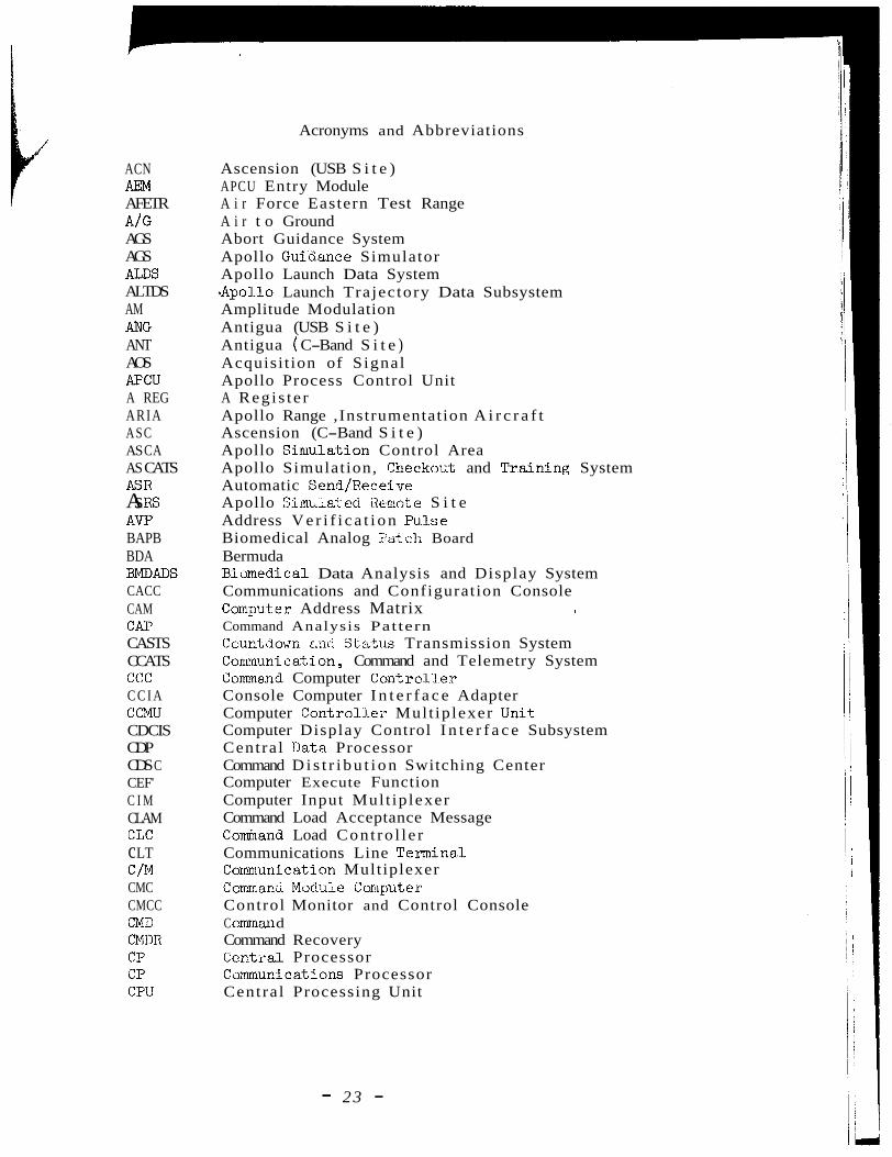
Acronyms and Abbreviations
Ascension (USB S i t e ) APCU Entry Module A i r Force Eastern Test Range A i r t o Ground Abort Guidance System Apollo Guiaance Simulator Apollo Launch Data System -Apollo Launch Trajectory Data Subsystem Amplitude Modulation Antigua (USB S i t e ) Antigua ( C-Band S i t e ) Acquisi t ion of Signal Apollo Process Control Unit A Reg is te r Apollo Range ,Instrumentation A i r c r a f t Ascension (C-Band S i t e ) Apollo Sinlulation Control Area Apollo Simulation, Checkout and Tr.aining System Automatic SendlReceive Apollo S,!L~L.~& ed Hermte S i t e Address V e r i f i c a t i o n Pulse Biomedical Analog Ya.t c:h Board Bermuda Biamedical Data Analysis and Display System Communications and Configuration Console CorripxL2r Address Matrix i
Command Analysis Pattern Countdom c,r~cl St;nt:.I.s Transmission System Conmunica.tion, Command and Telemetry System Cornland Computer Cont rc l l e r Console Computer I n t e r f a c e Adapter Computer Control.l.er Mul t ip lexer Unit Computer Display Control I n t e r f a c e Subsystem Centra l Data Processor Command D i s t r i b u t i o n Switching Center Computer Execute Function Computer Input Mul t ip lexer Command Load Acceptance Message Comband Load Cont ro l l e r Communications Line Termina..l Communica.tion Multiplexer Commanci Module Corquter Control Monitor and Control Console C cmmm d Command Recovery Cenlxal Processor Communications Processor Centra l Processing Unit
- 23 -

PDSDD PM PR rf RKV
RS RSCC RSDP RSTC RTA RTC C RTDL RTDR
R /R
SALDS s /B S/C s cs s cu SDD SLY SMC SMCVG SMK SOM SSCR SSEU SSIA SSR TDDF TDP TESAC TICC TIP TLM TOB TTY TUT ucs UDB UHF US B VAL vco
VER VHF WB wwv- L
V/D
Acronyms and Abbreviations (Cont) I
P l o t t i n g Displays Subchannel Data D i s t r i b u t i o n Phas e Modulation P l o t t i n g Regis ter Radio Frequency Rose Knot Victor Recorder/Reproducer ,Remot e S i t e Remote S i t e Command Computer Remote S i t e Data Processor Remote S i t e Telemetry Computer Re a1 Time Ac cumulat ors R e d Time Computer Complex Real Time Data Link Real Time Data Router Simulated Apollo Launch Data System Switch Board Space Craft Standard Communications Subsystem System Configuration Unit Subchannel Data D i s t r i b u t o r Saturn Launch Vehicle System Monitor Cons o l e Simulated Memory Character Vector Generator Summary Message Keyboard S t a r t of Message Se lec t Source and Computer Recommendation System S e l e c t o r Extension Unit Slow Speed I n t e r f a c e Adapter S t a f f Support Room Telemetry Data Dis t r ibu t ion Frame Tracking Data Processor Telemetry Synchronizer and S e r i a l t o P a r a l l e l Converter Telemetry Instrumentat ion Contro l lers Console Telemetry Input Processor Telemetry Telemetry Output Buffer Teletype Telemetry User Table Univers a1 Command System Updat a Buffer Ultra High Frequency Unified S-Band Val1 dat ed Voltage Control led O s c i l l a t o r Voice /Dat a V e r i f i c a t i o n Very High Frequency Wide Band US Bureau Standards Time S t a t i o n (Boulder, Colorado)
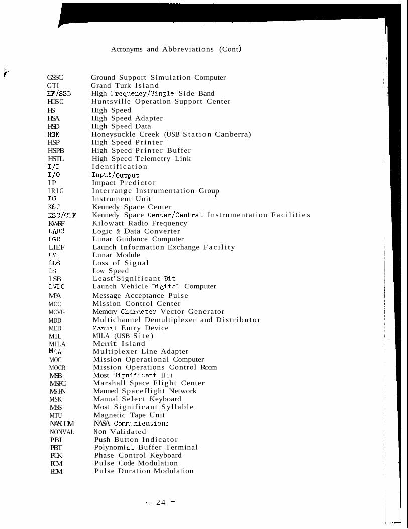
Acronyms and Abbreviations (Cont )
GSSC GTI
HOS C HS HSA HSD H S K HSP HSPB HSTL
HF/SSB
1 /D 1 /o I P I R I G I U KSC KSC/CIF KWRF LADC LGC LIEF LM LOS LS LSB LVDC MPA MCC MCVG MDD MED MIL MILA
MOC MOCR MSB MSFC MS FN MSK MSS MTU NASCOM NONVAL PBI PBT PCK PCM PDM
MLA
Ground Support Simulation Computer Grand Turk I s l a n d High Frequency/Single Side Band Huntsvi l le Operation Support Center High Speed High Speed Adapter High Speed Data Honeysuckle Creek (USB S t a t i o n Canberra) High Speed P r i n t e r High Speed P r i n t e r Buffer High Speed Telemetry Link I d e n t i f i c a t i o n
Impact P red ic t o r In te r range Instrumentation Group Instrument Unit Kennedy Space Center Kennedy Space Center/Central Ins t rumentat ion F a c i l i t i e s Kilowatt Radio Frequency Logic & Data Converter Lunar Guidance Computer Launch Information Exchange F a c i l i t y Lunar Module Loss of S igna l Low Speed Least ' S i g n i f i c a n t B i t Launch Vehicle T3igital Computer Message Acceptance Pulse Mission Control Center Memory Charact.er Vector Generator Multichannel Demultiplexer and D i s t r i b u t o r Mama1 Entry Device MILA (USB S i t e ) Merri t Is land Mult ip lexer Line Adapter Mission Operational Computer Mission Operations Control Room Most S i g n i f i c a n t H i t Marshall Space F l i g h t Center Manned Spacef l ight Network Manual Se lec t Keyboard Most S i g n i f i c a n t S y l l a b l e Magnetic Tape Unit NASA Comm~tnicatA.ons N on Vali dated Push Button I n d i c a t o r Polynomi a1 Buffer Terminal Phase Control Keyboard Pulse Code Modulation Pulse Duration Modulation
Input/output
*
- 2 4 -
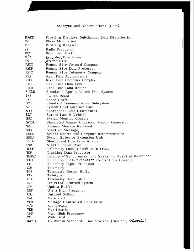
c Acronyms and Abbreviations (Cont )
PDSDD P l o t t i n g Displays Subchannel Data Dis t r ibu t ion m Phase Modulation PR P l o t t i n g Reg i s t e r r f Radio Frequency RKV Rose Knot Vic tor
RS ,Remot e S i t e RSCC Remote S i t e Command Computer RSDP Remote S i t e Data Processor RSTC Remote S i t e Telemetry Computer RTA Real Time Accumulators RTC C Real Time Computer Complex RTDL Real Time Data Link RTDR Real Time Data Router SALDS Simulated Apollo Launch Data System
R /R Recorder/Reproducer
s /B Switch Board s/c Space Craft scs Standard Communications Subsystem s cu System Configuration Unit SDD Subchannel Data Dis t r ibu to r SLY Saturn Launch Vehicle SMC System Monitor Console SMCVG Simulated Memory Character Vector Generator SMK Summary Message Keyboard
SS CR Se lec t Source and Computer Recommendation SSEU System S e l e c t o r Extension Unit SSIA Slow Speed I n t e r f a c e Adapter SSR S t a f f Support Room TDDF Telemetry Data Dis t r ibu t ion Frame
TESAC Telemetry' Synchronizer and S e r i a l t o P a r a l l e l conver ter T I CC Telemetry Instrumentat ion Contro l lers Console T I P Telemetry Input Processor
TOB Telemetry Output Buffer TTY Teletype TUT Telemetry User Table ucs Universal Command System UDB Updat a Buffer UHF U l t r a High Frequency USB Uni f i ed S-Band VAL Validated vco Voltage Control led O s c i l l a t o r V/D Voi c e /Dat a VER V e r i f i c a t i o n VHF Very High Frequency WB Wide Band
SOM S t a r t of Message,
TDP Tracking Data Processor
TLM Telemetry
wwv- L US Bureau Standards Time S t a t i o n (Boulder, COLOradO)