3 inch internal valve f660 series - meggitt...the 3-inch internal valve (valve) (see figure 1) is...
TRANSCRIPT
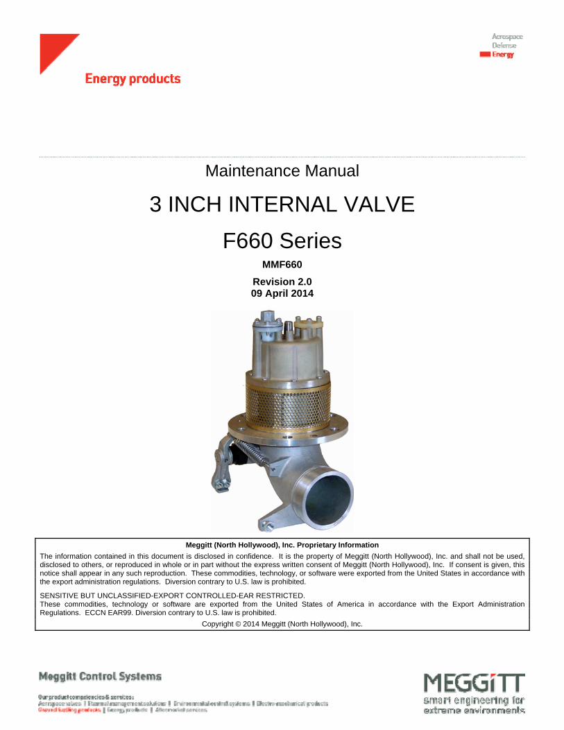
Maintenance Manual
3 INCH INTERNAL VALVE
F660 Series MMF660
Revision 2.0 09 April 2014
Meggitt (North Hollywood), Inc. Proprietary Information
The information contained in this document is disclosed in confidence. It is the property of Meggitt (North Hollywood), Inc. and shall not be used, disclosed to others, or reproduced in whole or in part without the express written consent of Meggitt (North Hollywood), Inc. If consent is given, this notice shall appear in any such reproduction. These commodities, technology, or software were exported from the United States in accordance with the export administration regulations. Diversion contrary to U.S. law is prohibited.
SENSITIVE BUT UNCLASSIFIED-EXPORT CONTROLLED-EAR RESTRICTED. These commodities, technology or software are exported from the United States of America in accordance with the Export Administration Regulations. ECCN EAR99. Diversion contrary to U.S. law is prohibited.
Copyright © 2014 Meggitt (North Hollywood), Inc.

Meggitt Fuelling Products Maintenance Manual (MMF660)
3 Inch Internal Valve – F660 Series
USE OR DISCLOSURE OF DATA ON THIS PAGE IS SUBJECT TO THE RESTRICTIONS ON THE TITLE PAGE OF THIS DOCUMENT
09 Apr 2014 Revision 2.0 i
REVISION RECORD
Keep this record in the front of the manual. When you get the revisions, put the revised pages in the manual. Write the revision number, date issued and your initials on this page.
Rev No. PAGES
AFFECTED DESCRIPTION OF
CHANGE DATE
APPROVED BY
1.0 ALL Initial Release 01/12/2001
1.1 ALL - 03/15/2002
1.2 ALL - 02/01/2006
2.0 ALL - 04/09/2014

Meggitt Fuelling Products Maintenance Manual (MMF660)
3 Inch Internal Valve – F660 Series
USE OR DISCLOSURE OF DATA ON THIS PAGE IS SUBJECT TO THE RESTRICTIONS ON THE TITLE PAGE OF THIS DOCUMENT
09 Apr 2014 Revision 2.0 ii
TABLE OF CONTENTS
SUBJECT PAGE
IMPORTANT SAFETY INSTRUCTIONS ........................................................................................................ A INTRODUCTION ............................................................................................................................................. 1 DESCRIPTION AND OPERATION ................................................................................................................. 2 FAULT ISOLATION ......................................................................................................................................... 6 DISASSEMBLY ............................................................................................................................................... 9 CLEANING .................................................................................................................................................... 12 CHECK/INSPECTION ................................................................................................................................... 14 ASSEMBLY ................................................................................................................................................... 15 ILLUSTRATED PARTS LIST ........................................................................................................................ 19
LIST OF ILLUSTRATIONS
FIGURE PAGE
Figure 1 . Internal Valve, 3-Inch ................................................................................................................. 3 Figure 2 . Envelope Dimensions ................................................................................................................ 5 Figure 3 . Cap Attaching Screw Tightening Sequence ............................................................................ 18
LIST OF TABLES
TABLE PAGE
Table 1. Leading Particulars ........................................................................................................................ 4 Table 2. Model Variations ............................................................................................................................ 4 Table 3. Fault Isolation ................................................................................................................................ 6 Table 4. Recommended Cleaning Materials ............................................................................................. 12 Table 5. Component Checks ..................................................................................................................... 14 Table 6. Recommended Assembly Materials ............................................................................................ 15
Meggitt Fuelling Products Maintenance Manual (MMF660)
3 Inch Internal Valve – F660 Series
USE OR DISCLOSURE OF DATA ON THIS PAGE IS SUBJECT TO THE RESTRICTIONS ON THE TITLE PAGE OF THIS DOCUMENT
09 Apr 2014 Revision 2.0 A
IMPORTANT SAFETY INSTRUCTIONS
SAVE THESE INSTRUCTIONS!
This manual contains important instructions that shall be followed during installation and maintenance of the 3 Inch Internal Valve (valve). The following are general safety precautions that are not related to specific procedures and therefore do not appear elsewhere in this publication. These are recommended precautions that personnel must understand and apply during maintenance.
The valve is a mechanical device and can be dangerous if incorrectly operated or maintained.
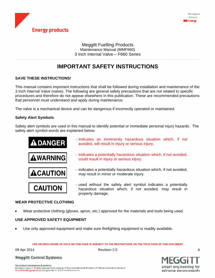
Safety Alert Symbols
Safety alert symbols are used in this manual to identify potential or immediate personal injury hazards. The safety alert symbol words are explained below:
- indicates an imminently hazardous situation which, if not avoided, will result in injury or serious injury.
- indicates a potentially hazardous situation which, if not avoided, could result in injury or serious injury.
- indicates a potentially hazardous situation which, if not avoided, may result in minor or moderate injury.
- used without the safety alert symbol indicates a potentially hazardous situation which, if not avoided, may result in property damage.
WEAR PROTECTIVE CLOTHING
Wear protective clothing (gloves, apron, etc.) approved for the materials and tools being used.
USE APPROVED SAFETY EQUIPMENT
Use only approved equipment and make sure firefighting equipment is readily available.
Meggitt Fuelling Products Maintenance Manual (MMF660)
3 Inch Internal Valve – F660 Series
USE OR DISCLOSURE OF DATA ON THIS PAGE IS SUBJECT TO THE RESTRICTIONS ON THE TITLE PAGE OF THIS DOCUMENT
09 Apr 2014 Revision 2.0 B
GIVE CLEANERS SPECIAL CARE
When cleaners are being used read and follow the material safety data sheet (MSDS) instructions for correct handling.
Equipment Safety Information
The following safety information briefly discusses hazards peculiar to the equipment, which are likely to be encountered during maintenance activity.
GENERAL OPERATING LOCATION PRECAUTIONS
Use only authorized replacement parts or hardware.
Obey Lock-Out/Tag-Out procedures when working on the valve.
OPERATION AND MAINTENANCE OF FUEL SYSTEMS
Protect all fuel lines from damage or puncture. Do not operate the valve if a fuel leak is detected.
Do not use flammable solvents for cleaning parts.
Check for tools, rags, or loose parts left in the area before resuming operation.
Do not attempt to remove the valve from the system without first isolating it from the line pressure and venting all of the trapped internal pressure.
Meggitt Fuelling Products Maintenance Manual (MMF660)
3 Inch Internal Valve – F660 Series
USE OR DISCLOSURE OF DATA ON THIS PAGE IS SUBJECT TO THE RESTRICTIONS ON THE TITLE PAGE OF THIS DOCUMENT
09 Apr 2014 Revision 2.0 1
INTRODUCTION
1. General
The information and procedures contained in this manual have been prepared to assist qualified repair personnel in off-aircraft maintenance of the 3-Inch Internal Valve. The instructions provide information necessary to perform maintenance functions. The valve is manufactured by Meggitt (North Hollywood), Inc., 12838 Saticoy Street, North Hollywood, California 91605.
2. Scope
The instructions contained in this manual do not claim to cover all details or variations in equipment. They do not provide for every problem that could occur during installation, operation, or maintenance. If further information is required, contact Meggitt (North Hollywood), Inc., Product Support Department.
3. Standard Shop Practices
Use approved procedures and safety precautions to prevent damage to the equipment and injury to personnel.
4. Weights and Measurements
Weights and measurements in this manual are expressed in both English (U.S. customary) and Metric (SI) units.
5. Revision Service
This manual will be revised, as necessary, to reflect current information.
Meggitt Fuelling Products Maintenance Manual (MMF660)
3 Inch Internal Valve – F660 Series
USE OR DISCLOSURE OF DATA ON THIS PAGE IS SUBJECT TO THE RESTRICTIONS ON THE TITLE PAGE OF THIS DOCUMENT
09 Apr 2014 Revision 2.0 2
DESCRIPTION AND OPERATION
1. Description
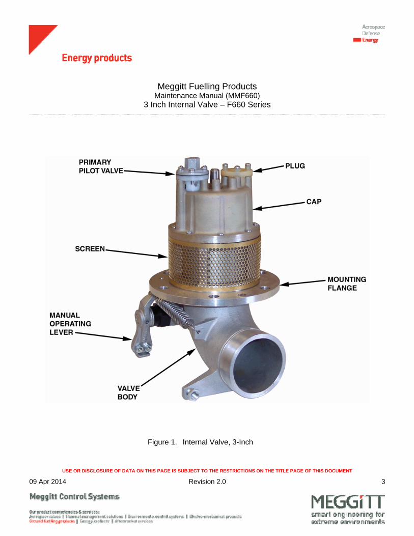
The 3-Inch Internal Valve (valve) (See Figure 1) is designed to provide normal and emergency shutoff functions and tank liquid level control with low surge, low pressure drop, and high reliability. When used with the F613 jet level sensor, fuel pressure provides the actuation force for opening and closing the valve during tank filling.
The basic valve can be used for off-loading. Single or dual stage tank filling control is available by adding one or two pilot valves. A lever is provided for attachment of a cable to open the valve during off-loading.
2. Operation
A. Starting Fuel Flow into the Tank
Fuel flow into the tank commences when the upstream fuel pressure is applied both to the pilot valve(s) and to the valve inlet (main piston). When the fuel pressure applied to the pilot valve increases to approximately 6 psi (41.36 kPa), the pilot valve will open. When the pilot valve opens, the fuel trapped in the main piston chamber is relieved into the tank. The upstream pressure then opens the main piston, establishing flow into the tank.
B. Stopping Fuel Flow into the Tank
Fuel flow into the tank stops when the fuel level reaches the F613 jet level sensor shutoff point. Pressure to the pilot valve is relieved and the pilot valve closes. When the pilot valve closes, fuel fills the main piston chamber and the main piston is closed by spring force and fuel pressure.
C. Off-Loading Fuel
Fuel off-loading is accomplished by manually operating the lever. The lever pushes the main piston to its open position, allowing fuel to flow.
Meggitt Fuelling Products Maintenance Manual (MMF660)
3 Inch Internal Valve – F660 Series
USE OR DISCLOSURE OF DATA ON THIS PAGE IS SUBJECT TO THE RESTRICTIONS ON THE TITLE PAGE OF THIS DOCUMENT
09 Apr 2014 Revision 2.0 3
Figure 1. Internal Valve, 3-Inch
Meggitt Fuelling Products Maintenance Manual (MMF660)
3 Inch Internal Valve – F660 Series
USE OR DISCLOSURE OF DATA ON THIS PAGE IS SUBJECT TO THE RESTRICTIONS ON THE TITLE PAGE OF THIS DOCUMENT
09 Apr 2014 Revision 2.0 4
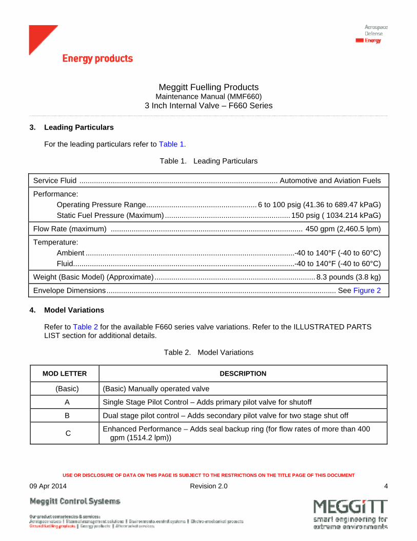
3. Leading Particulars
For the leading particulars refer to Table 1.
Table 1. Leading Particulars
Service Fluid ............................................................................................... Automotive and Aviation Fuels
Performance:
Operating Pressure Range ..................................................... 6 to 100 psig (41.36 to 689.47 kPaG)
Static Fuel Pressure (Maximum) ............................................................ 150 psig ( 1034.214 kPaG)
Flow Rate (maximum) ............................................................................................ 450 gpm (2,460.5 lpm)
Temperature:
Ambient .................................................................................................... -40 to 140°F (-40 to 60°C)
Fluid .......................................................................................................... -40 to 140°F (-40 to 60°C)
Weight (Basic Model) (Approximate) ............................................................................. 8.3 pounds (3.8 kg)
Envelope Dimensions .............................................................................................................. See Figure 2
4. Model Variations
Refer to Table 2 for the available F660 series valve variations. Refer to the ILLUSTRATED PARTS LIST section for additional details.
Table 2. Model Variations
MOD LETTER DESCRIPTION
(Basic) (Basic) Manually operated valve
A Single Stage Pilot Control – Adds primary pilot valve for shutoff
B Dual stage pilot control – Adds secondary pilot valve for two stage shut off
C Enhanced Performance – Adds seal backup ring (for flow rates of more than 400
gpm (1514.2 lpm))

Meggitt Fuelling Products Maintenance Manual (MMF660)
3 Inch Internal Valve – F660 Series
USE OR DISCLOSURE OF DATA ON THIS PAGE IS SUBJECT TO THE RESTRICTIONS ON THE TITLE PAGE OF THIS DOCUMENT
09 Apr 2014 Revision 2.0 5
Figure 2. Envelope Dimensions

Meggitt Fuelling Products Maintenance Manual (MMF660)
3 Inch Internal Valve – F660 Series
USE OR DISCLOSURE OF DATA ON THIS PAGE IS SUBJECT TO THE RESTRICTIONS ON THE TITLE PAGE OF THIS DOCUMENT
09 Apr 2014 Revision 2.0 6
FAULT ISOLATION
1. General
This section contains fault isolation procedures for the valve. Operate the valve in accordance with the Operation section, if the valve fails to operate correctly refer to Table 3 and select the appropriate action. Table 3 identifies the Fault, Probable Cause and Corrective Action.
Table 3. Fault Isolation
FAULT PROBABLE CAUSE CORRECTIVE ACTION
BOTTOM FILLING OPERATION
Valve will not open Insufficient fuel pressure at pilot valve (IPL Figure 1, 1)
Check and correct the fuel pressure supply.
Pilot valve diaphragm (IPL Figure 2, 3) leaking
Overhaul or replace the pilot valve.
Jammed main piston (IPL Figure 1, 14) due to contamination
Overhaul the valve.
Surging fuel flow Insufficient fuel pressure at pilot valve (IPL Figure 1, 1)
Check and correct the fuel pressure supply.
Valve will not close Jammed main piston (IPL Figure 1, 14)
Overhaul the valve.
Main piston seal (IPL Figure 1, 11) damaged (deformed)
Replace the seal and install backup ring (IPL Figure 1, 11A) (install kit, P/N KITF660-301).
Operating cable incorrectly adjusted Adjust the operating cable.
Incorrectly installed or damaged plug (IPL Figure 1, 5)
Install the plug correctly. Replace the plug if damaged.

Meggitt Fuelling Products Maintenance Manual (MMF660)
3 Inch Internal Valve – F660 Series
USE OR DISCLOSURE OF DATA ON THIS PAGE IS SUBJECT TO THE RESTRICTIONS ON THE TITLE PAGE OF THIS DOCUMENT
09 Apr 2014 Revision 2.0 7
Table 3. Fault Isolation – Continued
FAULT PROBABLE CAUSE CORRECTIVE ACTION
Valve will not close (continued)
Tension spring (IPL Figure 1, 33) missing or disconnected
Replace or connect the spring.
Internal leakage Main piston seal (IPL Figure 1, 11) damaged (deformed)
Replace the seal and install backup ring (IPL Figure 1, 11A) (install kit, P/N KITF660-301).
Damaged seat on main piston (IPL Figure 1, 14) or contamination of sealing surfaces
Overhaul the valve.
Disconnected or damaged plug (IPL Figure 1, 5)
Check connection, or replace plug as necessary.
OFF-LOADING OPERATION
Valve will not open Operating cable incorrectly adjusted Adjust the operating cable.
Jammed main piston (IPL Figure 1, 14) due to contamination
Overhaul the valve.
Main piston seal (IPL Figure 1, 11) damaged (deformed)
Replace the seal and install backup ring (IPL Figure 1, 11A) (install kit, P/N KITF660-301).
Valve will not close Jammed main piston (IPL Figure 1, 14) due to contamination
Overhaul the valve.
Main piston seal (IPL Figure 1, 11) damaged (deformed)
Replace the seal and install backup ring (IPL Figure 1, 11A) (install kit, P/N KITF660-301).
Operating cable incorrectly adjusted Adjust the operating cable.

Meggitt Fuelling Products Maintenance Manual (MMF660)
3 Inch Internal Valve – F660 Series
USE OR DISCLOSURE OF DATA ON THIS PAGE IS SUBJECT TO THE RESTRICTIONS ON THE TITLE PAGE OF THIS DOCUMENT
09 Apr 2014 Revision 2.0 8
Table 3. Fault Isolation – Continued
FAULT PROBABLE CAUSE CORRECTIVE ACTION
Leakage when valve is closed
NOTE: Leakage up to 20 cc/min is allowed.
Contaminated pilot valve (IPL Figure 1, 1)
Overhaul or replace the pilot valve.
Excessively worn or contaminated main piston seal (IPL Figure 1, 11)
Replace the seal.
Excessively worn or contaminated quad ring (IPL Figure 1, 9)
Replace the quad ring.
Damaged seat on main piston (IPL Figure 1, 14) or contamination of sealing surfaces
Overhaul the valve.
Shaft leakage Excessively worn or contaminated quad ring (IPL Figure 1, 38)
Replace the quad ring.
Excessively worn or contaminated packing (IPL Figure 1, 40)
Replace the packing.
Meggitt Fuelling Products Maintenance Manual (MMF660)
3 Inch Internal Valve – F660 Series
USE OR DISCLOSURE OF DATA ON THIS PAGE IS SUBJECT TO THE RESTRICTIONS ON THE TITLE PAGE OF THIS DOCUMENT
09 Apr 2014 Revision 2.0 9
DISASSEMBLY
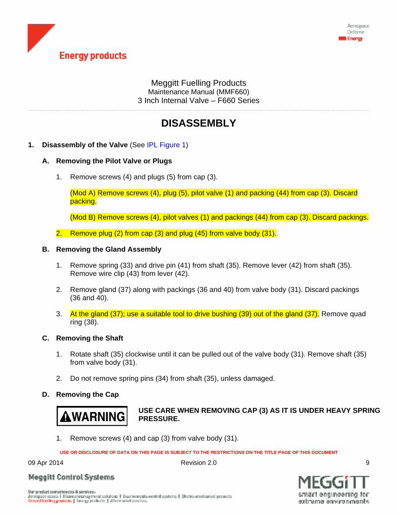
1. Disassembly of the Valve (See IPL Figure 1)
A. Removing the Pilot Valve or Plugs
1. Remove screws (4) and plugs (5) from cap (3).
(Mod A) Remove screws (4), plug (5), pilot valve (1) and packing (44) from cap (3). Discard packing.
(Mod B) Remove screws (4), pilot valves (1) and packings (44) from cap (3). Discard packings.
2. Remove plug (2) from cap (3) and plug (45) from valve body (31).
B. Removing the Gland Assembly
1. Remove spring (33) and drive pin (41) from shaft (35). Remove lever (42) from shaft (35). Remove wire clip (43) from lever (42).
2. Remove gland (37) along with packings (36 and 40) from valve body (31). Discard packings (36 and 40).
3. At the gland (37); use a suitable tool to drive bushing (39) out of the gland (37). Remove quad ring (38).
C. Removing the Shaft
1. Rotate shaft (35) clockwise until it can be pulled out of the valve body (31). Remove shaft (35) from valve body (31).
2. Do not remove spring pins (34) from shaft (35), unless damaged.
D. Removing the Cap
USE CARE WHEN REMOVING CAP (3) AS IT IS UNDER HEAVY SPRING PRESSURE.
1. Remove screws (4) and cap (3) from valve body (31).
Meggitt Fuelling Products Maintenance Manual (MMF660)
3 Inch Internal Valve – F660 Series
USE OR DISCLOSURE OF DATA ON THIS PAGE IS SUBJECT TO THE RESTRICTIONS ON THE TITLE PAGE OF THIS DOCUMENT
09 Apr 2014 Revision 2.0 10
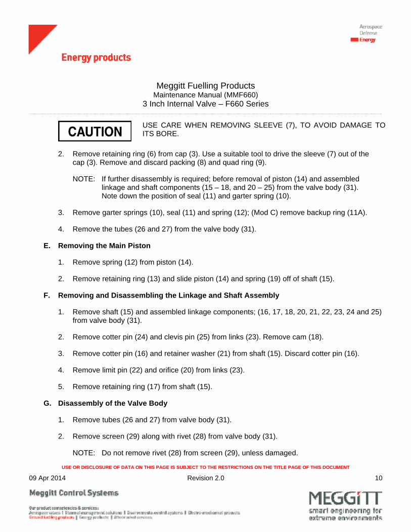
USE CARE WHEN REMOVING SLEEVE (7), TO AVOID DAMAGE TO ITS BORE.
2. Remove retaining ring (6) from cap (3). Use a suitable tool to drive the sleeve (7) out of the cap (3). Remove and discard packing (8) and quad ring (9).
NOTE: If further disassembly is required; before removal of piston (14) and assembled linkage and shaft components (15 – 18, and 20 – 25) from the valve body (31). Note down the position of seal (11) and garter spring (10).
3. Remove garter springs (10), seal (11) and spring (12); (Mod C) remove backup ring (11A).
4. Remove the tubes (26 and 27) from the valve body (31).
E. Removing the Main Piston
1. Remove spring (12) from piston (14).
2. Remove retaining ring (13) and slide piston (14) and spring (19) off of shaft (15).
F. Removing and Disassembling the Linkage and Shaft Assembly
1. Remove shaft (15) and assembled linkage components; (16, 17, 18, 20, 21, 22, 23, 24 and 25) from valve body (31).
2. Remove cotter pin (24) and clevis pin (25) from links (23). Remove cam (18).
3. Remove cotter pin (16) and retainer washer (21) from shaft (15). Discard cotter pin (16).
4. Remove limit pin (22) and orifice (20) from links (23).
5. Remove retaining ring (17) from shaft (15).
G. Disassembly of the Valve Body
1. Remove tubes (26 and 27) from valve body (31).
2. Remove screen (29) along with rivet (28) from valve body (31).
NOTE: Do not remove rivet (28) from screen (29), unless damaged.

Meggitt Fuelling Products Maintenance Manual (MMF660)
3 Inch Internal Valve – F660 Series
USE OR DISCLOSURE OF DATA ON THIS PAGE IS SUBJECT TO THE RESTRICTIONS ON THE TITLE PAGE OF THIS DOCUMENT
09 Apr 2014 Revision 2.0 11
3. Remove bushing (32) from valve body (31).
NOTE: Do not remove spring pin (30) from valve body (31), unless damaged.
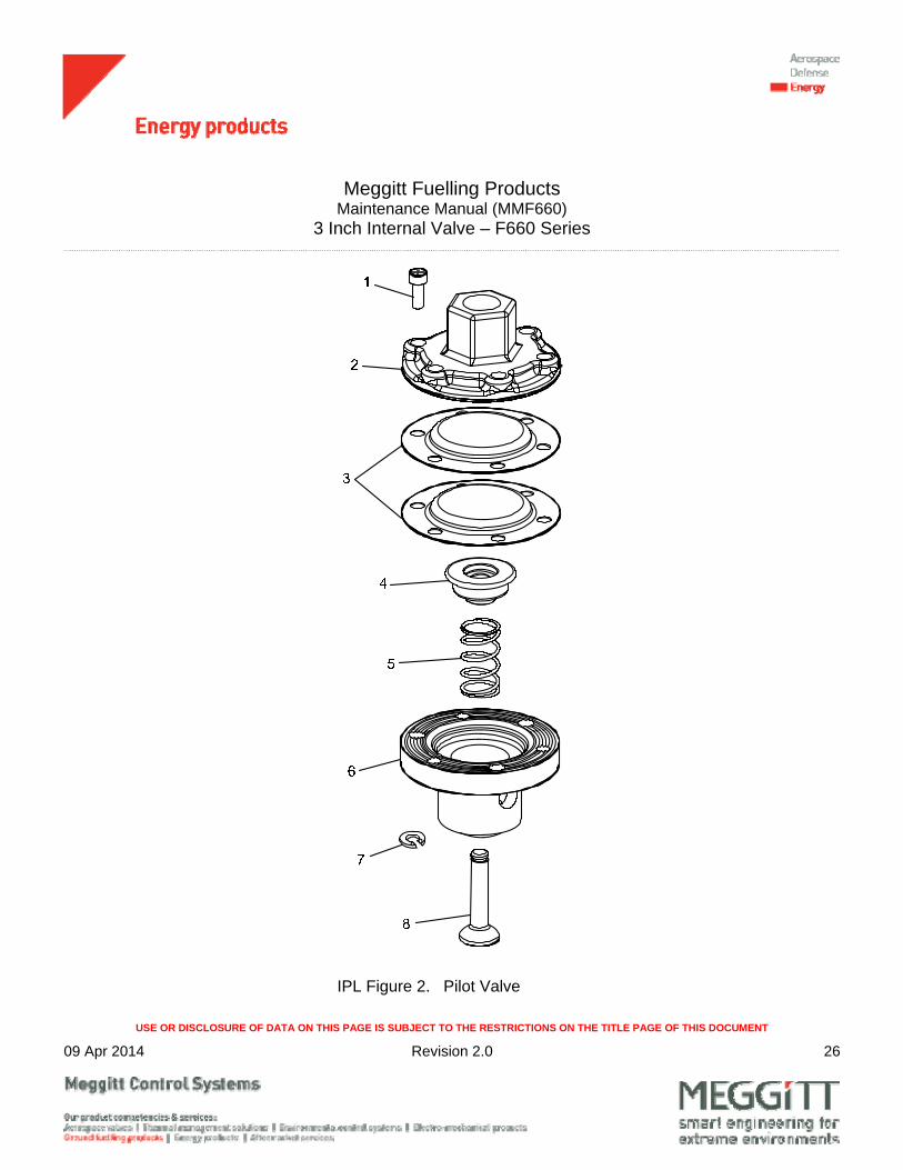
2. Disassembly of the Pilot Valve (See IPL Figure 2)
A. Remove screws (1) and cover (2) from base (6).
B. Remove diaphragms (3) from base (6).
C. Remove retaining ring (7), spring retainer (4), spring (5) and poppet (8) from base (6).
Meggitt Fuelling Products Maintenance Manual (MMF660)
3 Inch Internal Valve – F660 Series
USE OR DISCLOSURE OF DATA ON THIS PAGE IS SUBJECT TO THE RESTRICTIONS ON THE TITLE PAGE OF THIS DOCUMENT
09 Apr 2014 Revision 2.0 12
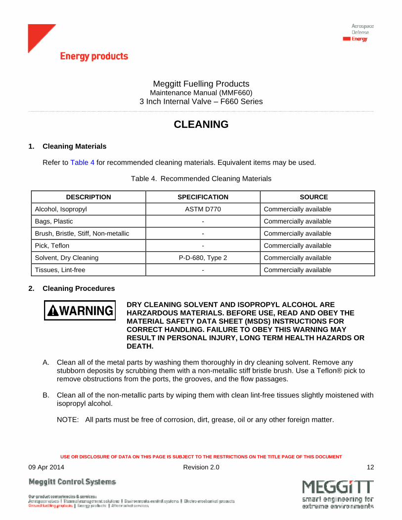
CLEANING
1. Cleaning Materials
Refer to Table 4 for recommended cleaning materials. Equivalent items may be used.
Table 4. Recommended Cleaning Materials
DESCRIPTION SPECIFICATION SOURCE
Alcohol, Isopropyl ASTM D770 Commercially available
Bags, Plastic - Commercially available
Brush, Bristle, Stiff, Non-metallic - Commercially available
Pick, Teflon - Commercially available
Solvent, Dry Cleaning P-D-680, Type 2 Commercially available
Tissues, Lint-free - Commercially available
2. Cleaning Procedures
DRY CLEANING SOLVENT AND ISOPROPYL ALCOHOL ARE HARZARDOUS MATERIALS. BEFORE USE, READ AND OBEY THE MATERIAL SAFETY DATA SHEET (MSDS) INSTRUCTIONS FOR CORRECT HANDLING. FAILURE TO OBEY THIS WARNING MAY RESULT IN PERSONAL INJURY, LONG TERM HEALTH HAZARDS OR DEATH.
A. Clean all of the metal parts by washing them thoroughly in dry cleaning solvent. Remove any stubborn deposits by scrubbing them with a non-metallic stiff bristle brush. Use a Teflon® pick to remove obstructions from the ports, the grooves, and the flow passages.
B. Clean all of the non-metallic parts by wiping them with clean lint-free tissues slightly moistened with isopropyl alcohol.
NOTE: All parts must be free of corrosion, dirt, grease, oil or any other foreign matter.

Meggitt Fuelling Products Maintenance Manual (MMF660)
3 Inch Internal Valve – F660 Series
USE OR DISCLOSURE OF DATA ON THIS PAGE IS SUBJECT TO THE RESTRICTIONS ON THE TITLE PAGE OF THIS DOCUMENT
09 Apr 2014 Revision 2.0 13
WEAR EYE PROTECTION WHEN DRYING PARTS WITH COMPRESSED AIR. DO NOT DIRECT AIRSTREAM AT PERSONNEL OR LIGHT METAL PARTS.
C. Dry the parts with clean lint-free tissues or clean, dry, compressed air.
D. Package all of the clean parts in plastic bags.
Meggitt Fuelling Products Maintenance Manual (MMF660)
3 Inch Internal Valve – F660 Series
USE OR DISCLOSURE OF DATA ON THIS PAGE IS SUBJECT TO THE RESTRICTIONS ON THE TITLE PAGE OF THIS DOCUMENT
09 Apr 2014 Revision 2.0 14
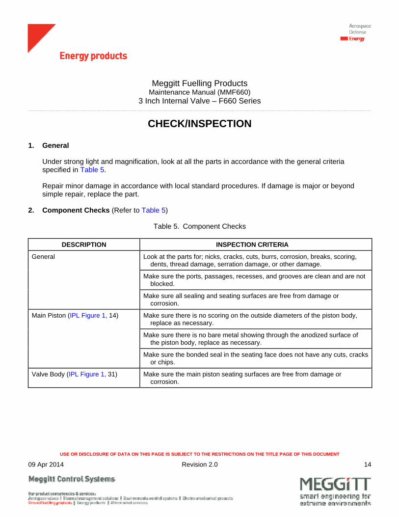
CHECK/INSPECTION
1. General
Under strong light and magnification, look at all the parts in accordance with the general criteria specified in Table 5.
Repair minor damage in accordance with local standard procedures. If damage is major or beyond simple repair, replace the part.
2. Component Checks (Refer to Table 5)
Table 5. Component Checks
DESCRIPTION INSPECTION CRITERIA
General Look at the parts for; nicks, cracks, cuts, burrs, corrosion, breaks, scoring, dents, thread damage, serration damage, or other damage.
Make sure the ports, passages, recesses, and grooves are clean and are not blocked.
Make sure all sealing and seating surfaces are free from damage or corrosion.
Main Piston (IPL Figure 1, 14) Make sure there is no scoring on the outside diameters of the piston body, replace as necessary.
Make sure there is no bare metal showing through the anodized surface of the piston body, replace as necessary.
Make sure the bonded seal in the seating face does not have any cuts, cracks or chips.
Valve Body (IPL Figure 1, 31) Make sure the main piston seating surfaces are free from damage or corrosion.
Meggitt Fuelling Products Maintenance Manual (MMF660)
3 Inch Internal Valve – F660 Series
USE OR DISCLOSURE OF DATA ON THIS PAGE IS SUBJECT TO THE RESTRICTIONS ON THE TITLE PAGE OF THIS DOCUMENT
09 Apr 2014 Revision 2.0 15
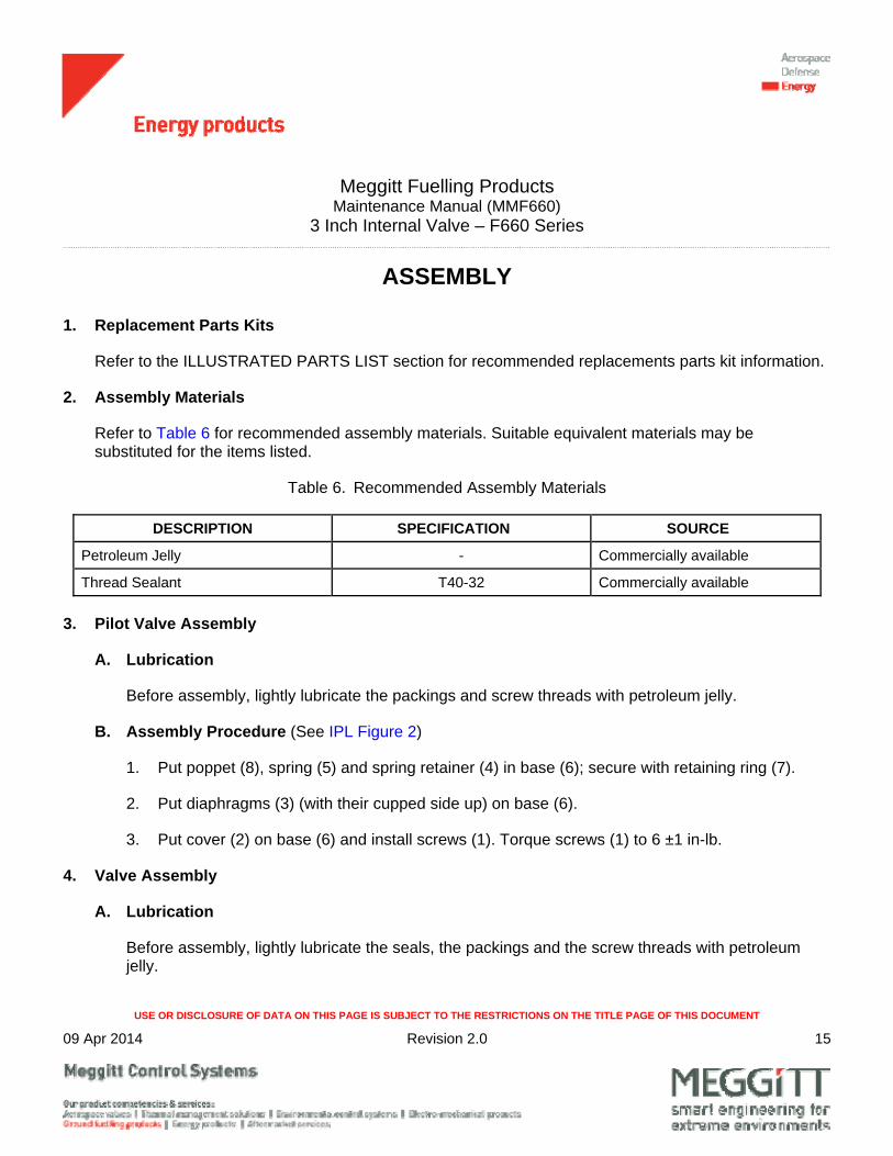
ASSEMBLY
1. Replacement Parts Kits
Refer to the ILLUSTRATED PARTS LIST section for recommended replacements parts kit information.
2. Assembly Materials
Refer to Table 6 for recommended assembly materials. Suitable equivalent materials may be substituted for the items listed.
Table 6. Recommended Assembly Materials
DESCRIPTION SPECIFICATION SOURCE
Petroleum Jelly - Commercially available
Thread Sealant T40-32 Commercially available
3. Pilot Valve Assembly
A. Lubrication
Before assembly, lightly lubricate the packings and screw threads with petroleum jelly.
B. Assembly Procedure (See IPL Figure 2)
1. Put poppet (8), spring (5) and spring retainer (4) in base (6); secure with retaining ring (7).
2. Put diaphragms (3) (with their cupped side up) on base (6).
3. Put cover (2) on base (6) and install screws (1). Torque screws (1) to 6 ±1 in-lb.
4. Valve Assembly
A. Lubrication
Before assembly, lightly lubricate the seals, the packings and the screw threads with petroleum jelly.
Meggitt Fuelling Products Maintenance Manual (MMF660)
3 Inch Internal Valve – F660 Series
USE OR DISCLOSURE OF DATA ON THIS PAGE IS SUBJECT TO THE RESTRICTIONS ON THE TITLE PAGE OF THIS DOCUMENT
09 Apr 2014 Revision 2.0 16
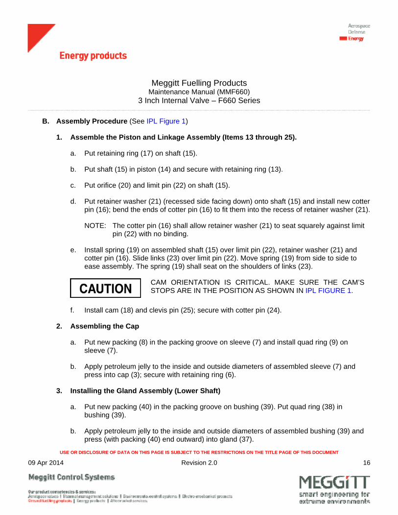
B. Assembly Procedure (See IPL Figure 1)
1. Assemble the Piston and Linkage Assembly (Items 13 through 25).
a. Put retaining ring (17) on shaft (15).
b. Put shaft (15) in piston (14) and secure with retaining ring (13).
c. Put orifice (20) and limit pin (22) on shaft (15).
d. Put retainer washer (21) (recessed side facing down) onto shaft (15) and install new cotter pin (16); bend the ends of cotter pin (16) to fit them into the recess of retainer washer (21).
NOTE: The cotter pin (16) shall allow retainer washer (21) to seat squarely against limit pin (22) with no binding.
e. Install spring (19) on assembled shaft (15) over limit pin (22), retainer washer (21) and cotter pin (16). Slide links (23) over limit pin (22). Move spring (19) from side to side to ease assembly. The spring (19) shall seat on the shoulders of links (23).
CAM ORIENTATION IS CRITICAL. MAKE SURE THE CAM’S STOPS ARE IN THE POSITION AS SHOWN IN IPL FIGURE 1.
f. Install cam (18) and clevis pin (25); secure with cotter pin (24).
2. Assembling the Cap
a. Put new packing (8) in the packing groove on sleeve (7) and install quad ring (9) on sleeve (7).
b. Apply petroleum jelly to the inside and outside diameters of assembled sleeve (7) and press into cap (3); secure with retaining ring (6).
3. Installing the Gland Assembly (Lower Shaft)
a. Put new packing (40) in the packing groove on bushing (39). Put quad ring (38) in bushing (39).
b. Apply petroleum jelly to the inside and outside diameters of assembled bushing (39) and press (with packing (40) end outward) into gland (37).

Meggitt Fuelling Products Maintenance Manual (MMF660)
3 Inch Internal Valve – F660 Series
USE OR DISCLOSURE OF DATA ON THIS PAGE IS SUBJECT TO THE RESTRICTIONS ON THE TITLE PAGE OF THIS DOCUMENT
09 Apr 2014 Revision 2.0 17
c. Put new packing (36) in the packing groove on gland (37).
4. Installing the Shaft and Lever Assembly
a. If removed, put spring pins (34) into shaft (35)
b. Slide assembled gland (36 thru 40) over shaft (35).
c. Put lever (42) on shaft (35) and install spring pin (41).
5. Installing the Piston and the Linkage Assembly into Valve Body
a. Put piston and linkage assembly into valve body (31).
CAM ORIENTATION IS CRITICAL. MAKE SURE THE CAM’S STOPS ARE IN THE POSITION AS SHOWN IN IPL FIGURE 1.
b. Put assembled shaft (35) and lever (42) into valve body (31). Make sure pins (34) and shaft (35) are correctly engaged with the cam (18). Torque gland (37) 80 to 100 lb-in. (9 to 11 Nm).
c. Put tubes (26 and 27) in valve body (31).
d. Slide screen (29) along with attached rivet (28) over valve body (31).
NOTE: If rivet (28) was removed from screen (29) do as follows:
1. Wrap screen (29) tightly around valve body (31), approximately in the center of the window. Secure screen (29) with rivet (28).
NOTE: Slight bending of the screen (29) wires is permitted to provide a good fit.
USE CARE WHEN INSTALLING SEAL (11) AS TO NOT DAMAGE IT DURING INSTALLATION.
e. Put seal (11) on piston (14). Put garter springs (10) over seal (11).
(Mod C) Install seal (11) and backup ring (11A) on the piston (14). Put garter springs (10) over the seal.
Meggitt Fuelling Products Maintenance Manual (MMF660)
3 Inch Internal Valve – F660 Series
USE OR DISCLOSURE OF DATA ON THIS PAGE IS SUBJECT TO THE RESTRICTIONS ON THE TITLE PAGE OF THIS DOCUMENT
09 Apr 2014 Revision 2.0 18
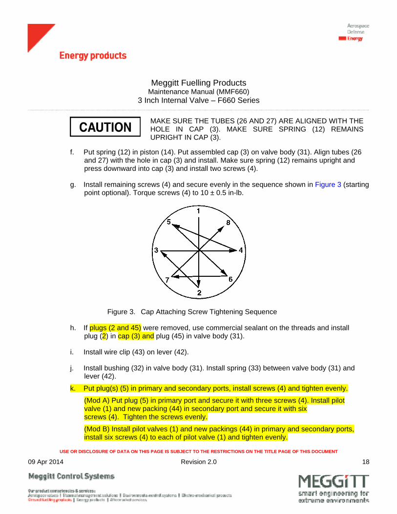
MAKE SURE THE TUBES (26 AND 27) ARE ALIGNED WITH THE HOLE IN CAP (3). MAKE SURE SPRING (12) REMAINS UPRIGHT IN CAP (3).
f. Put spring (12) in piston (14). Put assembled cap (3) on valve body (31). Align tubes (26 and 27) with the hole in cap (3) and install. Make sure spring (12) remains upright and press downward into cap (3) and install two screws (4).
g. Install remaining screws (4) and secure evenly in the sequence shown in Figure 3 (starting point optional). Torque screws (4) to 10 ± 0.5 in-lb.
Figure 3. Cap Attaching Screw Tightening Sequence
h. If plugs (2 and 45) were removed, use commercial sealant on the threads and install plug (2) in cap (3) and plug (45) in valve body (31).
i. Install wire clip (43) on lever (42).
j. Install bushing (32) in valve body (31). Install spring (33) between valve body (31) and lever (42).
k. Put plug(s) (5) in primary and secondary ports, install screws (4) and tighten evenly.
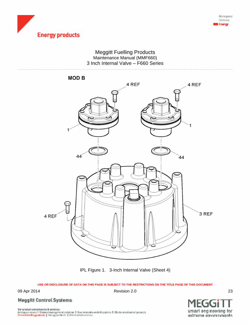
(Mod A) Put plug (5) in primary port and secure it with three screws (4). Install pilot valve (1) and new packing (44) in secondary port and secure it with six screws (4). Tighten the screws evenly.
(Mod B) Install pilot valves (1) and new packings (44) in primary and secondary ports, install six screws (4) to each of pilot valve (1) and tighten evenly.

Meggitt Fuelling Products Maintenance Manual (MMF660)
3 Inch Internal Valve – F660 Series
USE OR DISCLOSURE OF DATA ON THIS PAGE IS SUBJECT TO THE RESTRICTIONS ON THE TITLE PAGE OF THIS DOCUMENT
09 Apr 2014 Revision 2.0 19
ILLUSTRATED PARTS LIST
1. General
This section lists, describes, and illustrates all detail parts required for maintenance support of the 3 Inch Internal Valve (valve).
2. Scope of Information
The parts list is arranged in the general order of disassembly. The listing is indented to show the relationship between each part and its next higher assembly. Item numbers used in the parts list are keyed to the corresponding numbers of the accompanying illustration.
A. MODIFICATION CODE
The modification code indicates the parts usage with respect to the end item. When the MOD column is blank, the part usage is applicable to all versions unless otherwise specified in the DESCRIPTION column.
B. How to Identify a Part
When the part number is known: Refer to the parts list for the item number, description, modification codes, and quantity. Refer to the illustration to make sure of the physical appearance and location of the part.
When the part number is not known: Look at the illustrations to identify the part by physical appearance and location. Refer to the accompanying parts list to get the part number, nomenclature, modification codes, quantity, etc.
C. Abbreviations
ASSY Assembly
FIG. Figure
IPL Illustrated Parts List
MOD Modification

Meggitt Fuelling Products Maintenance Manual (MMF660)
3 Inch Internal Valve – F660 Series
USE OR DISCLOSURE OF DATA ON THIS PAGE IS SUBJECT TO THE RESTRICTIONS ON THE TITLE PAGE OF THIS DOCUMENT
09 Apr 2014 Revision 2.0 20
IPL Figure 1. 3-Inch Internal Valve (Sheet 1 of 4)

Meggitt Fuelling Products Maintenance Manual (MMF660)
3 Inch Internal Valve – F660 Series
USE OR DISCLOSURE OF DATA ON THIS PAGE IS SUBJECT TO THE RESTRICTIONS ON THE TITLE PAGE OF THIS DOCUMENT
09 Apr 2014 Revision 2.0 21
IPL Figure 1 3-Inch Internal Valve (Sheet 2 of 4)
VIEW B

Meggitt Fuelling Products Maintenance Manual (MMF660)
3 Inch Internal Valve – F660 Series
USE OR DISCLOSURE OF DATA ON THIS PAGE IS SUBJECT TO THE RESTRICTIONS ON THE TITLE PAGE OF THIS DOCUMENT
09 Apr 2014 Revision 2.0 22
IPL Figure 1. 3-Inch Internal Valve (Sheet 3 of 4)
Meggitt Fuelling Products Maintenance Manual (MMF660)
3 Inch Internal Valve – F660 Series
USE OR DISCLOSURE OF DATA ON THIS PAGE IS SUBJECT TO THE RESTRICTIONS ON THE TITLE PAGE OF THIS DOCUMENT
09 Apr 2014 Revision 2.0 23
IPL Figure 1. 3-Inch Internal Valve (Sheet 4)
Meggitt Fuelling Products Maintenance Manual (MMF660)
3 Inch Internal Valve – F660 Series
USE OR DISCLOSURE OF DATA ON THIS PAGE IS SUBJECT TO THE RESTRICTIONS ON THE TITLE PAGE OF THIS DOCUMENT
09 Apr 2014 Revision 2.0 24
FIG. ITEM PART NUMBER
DESCRIPTION 1 2 3 4 5 6 7
MOD CODES
UNITSPER
ASSY
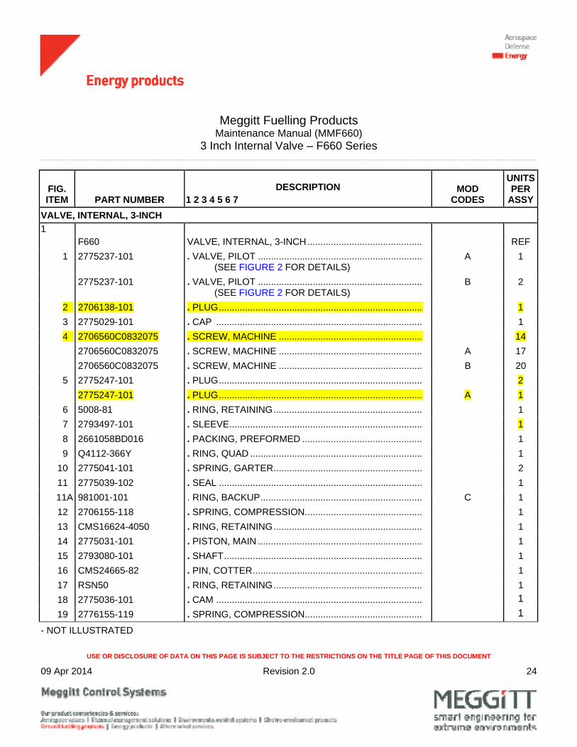
VALVE, INTERNAL, 3-INCH
1 F660 VALVE, INTERNAL, 3-INCH ............................................ REF
1 2775237-101 . VALVE, PILOT ............................................................... (SEE FIGURE 2 FOR DETAILS)
A 1
2775237-101 . VALVE, PILOT ............................................................... (SEE FIGURE 2 FOR DETAILS)
B 2
2 2706138-101 . PLUG .............................................................................. 1
3 2775029-101 . CAP ............................................................................... 1
4 2706560C0832075 . SCREW, MACHINE ....................................................... 14
2706560C0832075 . SCREW, MACHINE ....................................................... A 17
2706560C0832075 . SCREW, MACHINE ....................................................... B 20
5 2775247-101 . PLUG .............................................................................. 2
2775247-101 . PLUG .............................................................................. A 1
6 5008-81 . RING, RETAINING ......................................................... 1
7 2793497-101 . SLEEVE .......................................................................... 1
8 2661058BD016 . PACKING, PREFORMED .............................................. 1
9 Q4112-366Y . RING, QUAD .................................................................. 1
10 2775041-101 . SPRING, GARTER ......................................................... 2
11 2775039-102 . SEAL .............................................................................. 1
11A 981001-101 . RING, BACKUP .............................................................. C 1
12 2706155-118 . SPRING, COMPRESSION ............................................. 1
13 CMS16624-4050 . RING, RETAINING ......................................................... 1
14 2775031-101 . PISTON, MAIN ............................................................... 1
15 2793080-101 . SHAFT ............................................................................ 1
16 CMS24665-82 . PIN, COTTER ................................................................. 1
17 RSN50 . RING, RETAINING ......................................................... 1
18 2775036-101 . CAM ............................................................................... 1
19 2776155-119 . SPRING, COMPRESSION ............................................. 1
- NOT ILLUSTRATED

Meggitt Fuelling Products Maintenance Manual (MMF660)
3 Inch Internal Valve – F660 Series
USE OR DISCLOSURE OF DATA ON THIS PAGE IS SUBJECT TO THE RESTRICTIONS ON THE TITLE PAGE OF THIS DOCUMENT
09 Apr 2014 Revision 2.0 25
FIG. ITEM PART NUMBER
DESCRIPTION 1 2 3 4 5 6 7
MOD CODES
UNITSPER
ASSY
1 20 2793082-101 . ORIFICE ......................................................................... 1
21 2793089-101 . WASHER, RETAINER ................................................... 1
22 2793081-101 . PIN, LIMIT ...................................................................... 1
23 2775034-101 . LINK ............................................................................... 2
24 CMS24665-151 . PIN, COTTER ................................................................. 1
25 98306A159 . PIN, CLEVIS ................................................................... 1
26 2775053-101 . TUBE .............................................................................. 1
27 2775052-101 . TUBE (ALUMINUM) ....................................................... 1
28 CAN470A4-4 . RIVET, SOLID ................................................................ 2
29 2775153-101 . SCREEN ......................................................................... 1
30 CMS171648 . PIN, SPRING .................................................................. 1
31 2775027-101 . BODY, VALVE ................................................................ 1
32 2721205-1 . BUSHING ....................................................................... 1
33 2775163-101 . SPRING, TENSION ........................................................ 1
34 CMS171651 . PIN, SPRING .................................................................. 2
35 2775154-101 . SHAFT ............................................................................ 1
36 2661058BD121 . PACKING, PREFORMED .............................................. 1
37 2775042-101 . GLAND ........................................................................... 1
38 Q4114-366Y . RING, QUAD .................................................................. 1
39 2793360-101 . BUSHING ....................................................................... 1
40 2661058BD116 . PACKING, PREFORMED .............................................. 1
41 CMS171654 . PIN, SPRING .................................................................. 1
42 2775038-101 . LEVER ............................................................................ 1
43 3465T27 . CLIP, WIRE .................................................................... 1
44 2661058A016 . PACKING, PREFORMED .............................................. A 1
2661058A016 . PACKING, PREFORMED .............................................. B 2
45 2706138-101 . PLUG .............................................................................. 1
- NOT ILLUSTRATED
Meggitt Fuelling Products Maintenance Manual (MMF660)
3 Inch Internal Valve – F660 Series
USE OR DISCLOSURE OF DATA ON THIS PAGE IS SUBJECT TO THE RESTRICTIONS ON THE TITLE PAGE OF THIS DOCUMENT
09 Apr 2014 Revision 2.0 26
IPL Figure 2. Pilot Valve
Meggitt Fuelling Products Maintenance Manual (MMF660)
3 Inch Internal Valve – F660 Series
USE OR DISCLOSURE OF DATA ON THIS PAGE IS SUBJECT TO THE RESTRICTIONS ON THE TITLE PAGE OF THIS DOCUMENT
09 Apr 2014 Revision 2.0 27
FIG. ITEM PART NUMBER
DESCRIPTION 1 2 3 4 5 6 7
MOD CODES
UNITSPER
ASSY
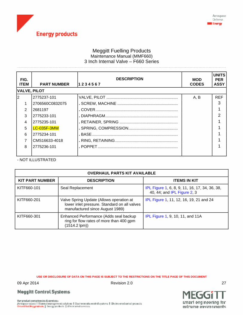
VALVE, PILOT
2 2775237-101 VALVE, PILOT ................................................................. A, B REF
1 2706560C0832075 . SCREW, MACHINE ....................................................... 3
2 2681197 . COVER ........................................................................... 1
3 2775233-101 . DIAPHRAGM .................................................................. 2
4 2775235-101 . RETAINER, SPRING ..................................................... 1
5 LC-035F-3MW . SPRING, COMPRESSION ............................................. 1
6 2775234-101 . BASE .............................................................................. 1
7 CMS16633-4018 . RING, RETAINING ......................................................... 1
8 2775236-101 . POPPET ......................................................................... 1
- NOT ILLUSTRATED
OVERHAUL PARTS KIT AVAILABLE
KIT PART NUMBER DESCRIPTION ITEMS IN KIT
KITF660-101 Seal Replacement IPL Figure 1, 6, 8, 9, 11, 16, 17, 34, 36, 38, 40, 44; and IPL Figure 2, 3
KITF660-201 Valve Spring Update (Allows operation at lower inlet pressure. Standard on all valves manufactured since August 1989)
IPL Figure 1, 11, 12, 16, 19, 21 and 24
KITF660-301 Enhanced Performance (Adds seal backup ring for flow rates of more than 400 gpm (1514.2 lpm))
IPL Figure 1, 9, 10, 11, and 11A