3 how linear motor proteins work
TRANSCRIPT

3
How Linear Motor Proteins Work
K. Oiwa1 and D.J. Manstein2
1 Kobe Advanced ICT Research Center (KARC), National Institute of Informationand Communications Technology, 588-2 Iwaoka, Nishi-ku, Kobe 651-2492, Japan
2 Institutes for Biophysical Chemistry and Structure Analysis, Hannover MedicalSchool, OE4350, Carl-Neuberg-Straße 1, D-30623 Hannover, Germany
3.1 Introduction
Most animals perform sophisticated forms of movement such as walking, run-ning, flying and swimming using their skeletal muscles. Although directedmovement is not generally associated with plants, cytoplasmic streaming inplant cells can reach velocities greater than 50 µm/s and thus constitutes oneof the fastest forms of directed movement. Unicellular eukaryotic organismsand prokaryotes display diverse mechanisms by which they are able to ac-tively move towards a food source, light or other sensory stimuli. On thecellular level active transport of vesicles and organelles is required, since thecytoplasm resembles a gel with a mesh size of approximately 50 nm, whichmakes the passive transport of organelle-sized particles impossible. For elon-gated cells such as neurons, even proteins and small metabolites have to beactively transported.
Linear motor proteins, moving on cytoskeletal filaments such as actin fila-ments and microtubules, are predominantly responsible for the motile activityin eukaryotic cells. They are chemo-mechanical enzymes that use the chem-ical energy from adenosinetriphosphate (ATP) hydrolysis to generate forceand to move cargoes along their filament tracks. Under physiological condi-tions, the energy input per molecule of ATP corresponds to the chemical freeenergy liberated by its hydrolysis to adenosinediphosphate (ADP) and inor-ganic phosphate (Pi), ca. 10−19 J (100 pNnm). The thermodynamic efficiencyof motor proteins varies between 30 and 60%. As machines, motor proteinsare unique since they convert chemical energy to mechanical work directly,rather than through an intermediate such as heat or electrical energy.
3.2 Structural Features of Cytoskeletal Motor Proteins
Three families of linear, cytoskeletal motor proteins have been described: ki-nesin, dynein, and myosin (Fig. 3.1). Kinesin and dynein family members
K. Oiwa and D.J. Manstein: How Linear Motor Proteins Work, Lect. Notes Phys. 711, 41–63(2007)DOI 10.1007/3-540-49522-3 3 c© Springer-Verlag Berlin Heidelberg 2007

42 K. Oiwa and D.J. Manstein
move along microtubules while the members of the extended myosin super-family move along actin filaments. The number of molecular engines and mo-tor proteins has greatly increased with the advance of the various genomeprojects. We now know more than eighteen myosin subfamilies or classes.Thirty-nine myosin heavy chain genes have been found in the human genome;nine of these are expressed in muscle tissues, while the remainders, the so-called unconventional myosins, are responsible for cell motilities other thanmuscle contraction. Fourteen subfamilies are known for kinesins and three fordyneins.
Comparisons of the available full-length sequences of dynein heavy chainshave shown that dynein is a member of the AAA+ (ATPase Associatedwith various cellular Activities) protein family [1]. So far, more than 200AAA+ family members have been identified that participate in diverse cellu-lar processes. Dyneins are further divided into two groups: cytoplasmic dyneinand axonemal dynein. Cytoplasmic dynein is composed of two identical heavychains of about 530 kDa each. Additionally, cytoplasmic dyneins consist oftwo 74 kDa intermediate chains, about four 53–59 kDa intermediate chains,and several light chains. Axonemal dynein shares the same heavy chain struc-ture but its overall structure is far more complicated and will not be discussedhere in detail (reviewed in [2]).
Dynein heavy chains consist of the C-terminal head with two elongatedflexible structures called the stalk (microtubule-binding domain) and the N-terminal tail (cargo-binding domain). The head and the stalk form a mo-tor domain (Fig. 3.1d). The motor domains of all dyneins are generally wellconserved in sequence (with 40–80% similarity) [3] and are indistinguishableby electron microscopy at the single-particle level (reviewed in [4]). A singledynein motor domain has a mass of almost 380 kDa. Most of this mass is con-tained in seven protein densities that encircle a cavity to produce a ring-likearchitecture, named a head ring. At least six of the seven densities probablycorrespond to the highly conserved AAA-modules containing specialized mo-tifs for ATP binding (e.g. P-loop motif). The first four of six AAA-modulesare predicted to bind nucleotides [5]. The first P-loop (P1) has the most highlyconserved sequence among dyneins and was previously assigned as the princi-pal site of ATP hydrolysis by vanadate-mediated photocleavage of the dyneinheavy chain. Further strong support for a functional role of P1 has been pro-vided by molecular dissection of cytoplasmic dyneins in which mutation ofthis P-loop abolished motor activitiy [4, 6]. The microtubule binding domainnamed the stalk, is flanked by two relatively long coiled-coil regions and isstructurally conserved among all dyneins. This stalk extends from the headbetween AAA-modules #4 and #5. Its tip interacts with microtubules in anATP-sensitive manner.
Based on electron microscopic observation of an axonemal dynein, ourgroup proposed a model in which multiple conformational changes are coor-dinated in such a way that the changes between the AAA domain #1 andits neighbors are amplified by the docking of the head ring onto a linker that

3 How Linear Motor Proteins Work 43
Fig. 3.1. Structure and topology of molecular motors. (a) Structure of the myosinmotor domain with light chain binding region. N-terminal domain, green; L50 oractin binding domain, cyan; U50, red; C-terminal domain, blue. The essential andregulatory light chains are colored yellow and magenta, respectively. (b) Structureof the kinesin 1 motor domain dimer. Switch-1 region, green; switch-2 region, cyan;neck linker and neck helix, blue. (c) Topological map of the myosin motor domain. Inaddition to the domains and subdomains shown, crystallographic results reveal thatthe segment between β7 and switch-2 moves as a solid body and can be regardedas an independent subdomain. Helices are shown as circles and β-strands as trian-gles. The background colours are: N-terminal SH3-like β-barrel, yellow; U50 sub-domain, pink; L50 subdomain, cyan; converter domain, light-blue. The 7-strandedcentral β-sheet is shown in red (β1 116–119; β2 122–126; β3 649–656; β4 173–178;β5 448–454; β6 240–247; β7 253–261) (modified from [7]). (d) Isolated moleculesof a monomeric flagellar inner arm dynein (subspecies c), imaged in two biochemi-cal states using negative staining electron microscopy. These images show that theADP.Vi-molecule has the same general form as the apo-molecule, but the latter ismore compact. Schematic diagram of the power stroke of axonemal dynein. Rigidcoupling between AAA domain #1 and a linker causes a rolling of the head towardsthe tail which translates the microtubule by 15 nm under zero load conditions. Thedistance between the tip of the stalk in these two conformations is approximately15 nm [8]

44 K. Oiwa and D.J. Manstein
connects the tail and the head ring [8] (Fig. 3.1d). When the stalk tip bindstightly to a microtubule, this may promote a concerted conformational changein AAA-modules #4 to #1, leading to activation of release of ADP and phos-phate from AAA-module #1. Rigid coupling between AAA-module #1 andlinker causes a rolling of the head towards the stem. The linker docks on thehead ring and the resultant rotation of the head ring swings the stalk. Judgingfrom the sequence and structural similarities between axonemal and cytoplas-mic dyneins, it appears reasonable to assume that the two dynein subfamiliesadopt the same mechanism for force generation.
Kinesin [9,10] and myosin [11] motor domains share a common core struc-ture even though they move on different filament tracks and the myosin motordomain is twice as large as the ∼350 residue kinesin motor domains (Fig. 3.1a,b). The core structure of kinesin and myosin motor domains is distantly re-lated to the GTPase subunit of heterotrimeric G proteins and small G-proteinsof the Ras family [12, 13]. The core structure includes three conserved se-quence motifs, termed P-loop, switch-1 and switch-2 at the nucleotide-bindingpocket, which act as γ-phosphate sensors. Their switching between ATP andADP states is associated with specific intramolecular movements, analogousto the nucleotide dependent conformational transitions in G-proteins, whichare central to the mechanism of kinesin and myosin family motors. To carryout directed movements, motor proteins must be able to associate with anddissociate from their filament tracks. All motor proteins have at least oneforce-producing motor domain that contains in addition to the active site,which is responsible for ATP binding and hydrolysis, a binding site for thecytoskeletal filament. In myosins and conventional kinesin, a neck domainconnects the motor domain to the tail region. The neck region of myosinsis formed by one or more so-called IQ motifs serving as binding sites forcalmodulin or calmodulin-like light chains (Fig. 3.1a). The resulting complexof extended α-helical heavy chain and tightly bound light chains serves as alever arm amplifying and redirecting smaller conformational changes withinthe myosin motor domain that occur during the interaction with nucleotideand filamentous actin (F-actin) [14,15]. The cargo-binding tail domain showshigh diversity both between motor families and within a single motor family.This enables different motors to bind different cargoes and thus to perform awide variety of cellular functions.
3.3 In Vitro Motility Assays: A Link between Physiologyand Biochemistry
A key issue in motor protein research is the mechanism of chemomechanicalcoupling. For myosin, we would like to understand how a series of chemicalevents such as ATP binding, hydrolysis of ATP, release of phosphate, andADP release induce changes in the ATP binding site, and how the changes

3 How Linear Motor Proteins Work 45
are coupled to events at the actin binding site and transmitted into large scalestructural changes leading to the production of working strokes of 5 to 50 nm.
Detailed structural information is required to unravel the mechanism bywhich force and movement are produced. In addition, to link the enzymekinetics of the motor protein ATPase in solution with the mechanics and en-ergetics of motor proteins, it is essential to use experimental systems in whichboth ATP-turnover and mechanical parameters can be accurately measured.Here, motor protein studies were advanced greatly by the development of invitro motility assays. In such assays, the motility of a system consisting only ofthe purified motor protein, F-actin or microtubules, ATP and buffer solutioncan be measured under well-defined conditions. The in vitro assay systemsare useful in filling the gap between the physiology and biochemistry of motorproteins because these systems enable us to directly observe force generationand movement involving only a very small number of protein molecules.
Two typical geometries are used for in vitro motility assays: bead assaysand surface assays (Fig. 3.2). In the former, filaments are fixed to a substrate,such as a microscope slide, and motors are attached to small plastic beads,typically 1 µm in diameter, or to the tip of a fine glass needle. The motionof the beads or of the needle along the filaments in the presence of ATPis visualized using a light microscope. Position and movement of the beadsor the needle are measured photo-electrically and can be determined with aresolution on the order of nanometers and sub-millisecond time-response. Inthe surface assays, the motors themselves are fixed to the substrate, and fila-ments are observed to diffuse down from solution, attach to and glide over themotor-coated surface. Visualization of the filaments is readily accomplishedusing dark-field or fluorescence microscopy. Measurements performed on largenumbers of enzyme molecules frequently hide important details of their mech-anism. Similarly, the discrete actions performed by individual motor proteinsare buried in the average when the net output from a large number of asyn-chronous motors is monitored. In recent decades, rapid progress in a numberof technologies such as atomic force microscopy, optical trap nanometry andfluorescence microscopy has provided us with tools to follow the dynamics ofsingle-molecules in situ with spatial and temporal resolution extending to theA and µs ranges. This allows the direct observation of the dynamic proper-ties of molecular motors, which macroscopic ensemble-averaged measurementscannot detect. Two fundamental motor protein parameters, coupling efficiencyand step-size, that can only be indirectly inferred from conventional in vitromotility assays are now accessible by single molecule approaches, permittingthe direct and simultaneous observation of ATP-turnover and force produc-tion.

46 K. Oiwa and D.J. Manstein
Fig. 3.2. Geometries for quantitative in vitro motility assays. (a) Motile activitycan be detected and quantified by attaching the motor to a bead and allowing it tointeract in an ATP-dependent manner with microtubules or oriented actin filamentson the cover glass surface. (b) Alternatively, individual fluorescence labelled andphalloidin-stabilized actin filaments can be observed moving over a lawn of myosinsand microtubules can be observed moving over a lawn of dynein or kinesin motors
3.4 Structural Features of the Myosin Motor Domain
The core of the myosin motor domain is formed by a central, 7-strandedβ-sheet and is surrounded by α-helices (Fig. 3.1a). The N-terminal 30 residuesof the myosin heavy chain extended between the motor domain and theneck region. Unless otherwise stated, sequence numbering refers to theDictyostelium myosin-II heavy chain. Residues 30–80 form a protruding SH3-like β-barrel domain. The function of this small domain is unknown; however,it is absent in class-I myosins and thus appears not to be essential for motoractivity. A large structural domain, which accounts for 6 of the 7 strands ofthe central β-sheet, is formed by residues 81–454 and 594–629 (Fig. 3.1c). Thisdomain is usually referred to as the upper 50K domain (U50). A large cleftdivides the U50 from the lower 50K domain (L50), a well defined structuraldomain formed by residues 465–590. The actin binding region and nucleotidebinding site of myosin are on opposite sides of the seven-stranded β-sheet andseparated by 40–50 A. The P-loop and the switch motifs are located in the U50domain and form part of the ATP binding site. Switch-1 and switch-2 contactthe nucleotide at the rear of the nucleotide binding pocket. The switch motifsmove towards each other when ATP is bound and move away from each otherin its absence. Conformational changes during the transition between differentnucleotide states do mostly correspond to rigid-body rotations of secondaryand tertiary structure elements. The motor domain can thus be regarded asconsisting of communicating functional units with substantial movement oc-curring in only a few residues.
Residues 630–670 form a long helix that runs from the actin binding regionat the tip of the large cleft to the 5th strand of the central β-sheet. A turn and

3 How Linear Motor Proteins Work 47
a broken helix are formed by residues 671–699. The segments of the brokenhelix are frequently referred to as SH1 and SH2-helices. The converter domainformed by residues 700–765 functions as a socket for the C-terminal light chainbinding domain and plays a key role in the communication between the activesite and neck region.
3.5 Amplification of the Working Strokeby a Lever Arm Mechanism
According to the lever arm model, the step size of myosins is predicted tobe proportional to the length of the neck region. An important feature ofthe lever arm model is that it has the neck region rigidly attached to theconverter domain. During the power stroke, converter domain and lever armswing together in a rigid body motion (Fig. 3.3a). The axis of rotation lies closeto and is oriented almost parallel to a long α-helix formed by residues 466–496, which is usually referred to as the relay helix (Fig. 3.1c). The swingingmovement, from an initial UP position to a DOWN position at the end ofthe working-stroke, is accompanied by the release of the hydrolysis productsinorganic phosphate and ADP. The actomyosin ATPase cycle (Fig. 3.4) can bedescribed by a number of intermediate states, which have ATP, its hydrolysisproducts or no nucleotide bound at the active site and display high or lowaffinity for F-actin.
The ATP-bound and nucleotide-free states are structurally and biochem-ically well-defined. They define extreme positions in regard to nucleotide andactin affinity as well as lever arm position. In the ATP-bound state, the affinityof myosin for F-actin is 10,000-fold reduced compared to the nucleotide-freeprotein. Conversely, strong binding to F-actin reduces the affinity for nu-cleotide 10,000-fold. The following sequence of events explains the reciprocalrelationship between actin and nucleotide affinity. The switch-1 loop preced-ing β2, the switch-2 loop following β3, and the P-loop following β4 undergolarge conformational changes upon ATP-binding. These movements of theactive site loops stabilize γ-phosphate binding and the coordination of theMg2+ ion. Additionally, the three edge β-strands: β5, β6, and β7 change theirorientation, which leads to large changes in the relative position of the U50and L50 subdomains and opening of the large cleft between them. Changes ofnucleotide binding loop structures are thereby coupled to large movements ofthe actin binding region. The central role played by the interaction between γ-phosphate and nucleotide-binding loops explains why ATP but not ADP caninduce the changes leading to low actin affinity. The establishment of a tightnetwork of hydrogen bonds in the final ATP-myosin complex is concomitantwith the formation of a proper active site. This allows the ATPase cycle toadvance to the myosin-ADP-Pi intermediate. However, ATP hydrolysis is notthe key step that drives the cycle forward. In fact the equilibrium constantfor the hydrolysis step is close to unity. What makes the cycle unidirectional

48 K. Oiwa and D.J. Manstein
Fig. 3.3. Mechanical models for myosin-based forward and backward movement.(a) Power-stroke of a conventional barbed plus-end directed myosin. (b) The in-sertion of a domain (red) between the converter region (blue) and the lever arm(orange) reverses the direction of the power-stroke and produces a minus-end di-rected myosin. The lever arm moves tangential to the long axis of the actin filament.The right hand panels show the myosin motor domain in the post power-stroke state(green) with an artificial lever arm consisting of two α-actinin repeats (blue) or twoα-actinin repeats and a directional inverted that is derived from the hGBP 4-helixbundle (red)
is the irreversibility of ATP binding. Binding of the myosin motor domain toactin induces a reversal of the sequence of conformational changes that are in-duced by ATP binding. Strong actin binding induces closing of the large cleftbetween U50 and L50 [16]; this leads to a distortion of the central β-sheet, theoutward movement of the nucleotide binding loops disrupts the coordinationof the Mg2+ ion and thereby ADP binding [17,18]. The loss of the Mg2+-ioncoordination induced by actin-binding is similar to the effect of GTPase ex-change factors on the release of GDP by small G-proteins. Therefore, actincan be viewed as an ADP-exchange factor for myosin [12, 18]. Concomitantwith the transition from the ATP-bound state to the rigor-like state, the leverarm swings from its UP position to the DOWN position [19].
The various genome projects have led to the identification of a large num-ber of new myosins and myosin classes. However, their characterisation isgreatly impeded by the fact that the sequencing projects cannot identify thelight chains that are associated with the individual myosin heavy chains. Inthe case of class-I myosins, analysis of the motor activity of the native pro-tein is further hampered by the presence of an ATP-insensitive actin-bindingsite in the tail region [20]. Here, the direct fusion of an artificial lever arm to

3 How Linear Motor Proteins Work 49
b
a
Fig. 3.4. Actomyosin ATPase cycle. (Upper panel) Mechanochemical scheme of theactomyosin ATPase cycle. Actin monomers are shown as golden spheres. The motordomain is colored metallic grey for the free form, purple for the weakly-bound form,and violet for the strongly-bound form. The converter is shown in blue and the leverarm in orange. Starting from the top-right the following sequence of events is shown:ATP binding induces dissociation of the actomyosin complex. The lever arm returnsin the pre-powerstroke position and ATP hydrolysis occurs. Actin-binding can bedescribed in terms of a three-state docking model. The initial formation of a weaklybound collision complex between the myosin head and F-actin is governed by longrange ionic interactions and is strongly dependent on ionic strength but indepen-dent of temperature. Strong binding is initiated by the following isomerisation tothe A-state, leading to the formation of stereospecific hydrophobic interactions. TheA-state is affected by organic solvent and temperature. Ionic strength has a compar-atively small effect on the formation of this state. The following stepwise transitionupon Pi release and then ADP release to a strongly bound state (R-state) involvesmajor structural rearrangements with formation of additional A-M contacts. Theconformational changes involve both hydrophobic and ionic interactions. In manymyosins both Pi and ADP release result in movement of the lever arm and con-tribute to the working stroke. The A-to-R transition is dependent on the effectiveconcentration of F-actin and hydrolysis products, as the reaction sequence is read-ily reversible [21]. (Lower panel) Minimal description of the myosin and actomyosinATPase as defined in solution. Vertical arrows indicate the actin association and dis-sociation from each myosin complex. In every case the events shown can be brokendown into a series of sub steps involving one or more identifiable protein confor-mational changes. The states with a yellow background represent the predominantpathway for the actomyosin ATPase (modified from [7])

50 K. Oiwa and D.J. Manstein
the motor domain greatly facilitates the production and characterization ofrecombinant myosin motors displaying full motile activity. It could be demon-strated that the kinetic properties of myosin motor domains from variousclasses are not affected by the fusion with an artificial lever arm [22,23]. Thereplacement of the native neck region with artificial lever arms is facilitatedby the limited number of contacts between the motor domain and the neckregion. The main technical problems that need to be overcome are the cre-ation of a stiff junction and tight control over the direction in which the leverprojects away from the motor domain. Spectrin-like repeats have been used toproduce constructs with artificial lever arms of different length for a varietyof unconventional myosins.
We applied this approach to characterize the motor properties of a myosinXI, which drives cytoplasmic streaming [22]. Cytoplasmic streaming, as foundin plant cells and algae, belongs with velocities of up to 100 µm s−1 to thefastest forms of actin-based motility. Electron microscopy of rotary shadowednative plant myosin XI show two head domains with elongated neck regionsthat are much larger than those observed with myosin II. The neck regionsjoin in a thin stalk of 25 nm length, which has two smaller globular domainsattached to its distal end. This structural organization is similar to that ofmyosin V, whose mechanical properties have been extensively studied [24].A Chara corallina myosin XI motor domain fused to two α-actinin repeats,corresponding to an artificial lever arm of approximately 12 nm length, movesactin filaments with a mean velocity of 16.2 µm/s in the in vitro motilityassay [22,25].
3.6 Backwards Directed Movement
Actin filaments are formed from G-actin monomers and microtubules fromα/β-tubulin dimers. Due to the head-to-tail arrangement of these constituentbuilding blocks, the resulting filaments are polar structures. The inherentpolarity of the filaments and the stereospecificity of their interactions withmotor proteins form the basis for directional movement in biological systems.Each individual type of motor protein moves towards either the plus or theminus end of its respective filament. The difference in the polymerization ratesdistinguish the fast-growing plus-ends from the slower-growing minus-ends.The directionality of a motor protein can be readily determined by in vitromotility assays. The minus-end of an actin filament or a microtubule can befluorescently labeled to distinguish it from the plus-end. Using this technique,it was discovered that, different from conventional kinesin, the kinesin-relatedprotein motors ncd [26] and Kar3 [27] are minus-end-directed microtubule-based motors and, different from conventional myosin, myosin VI [28,29] andmyosin IX [30] are minus-end directed actin-based motors.
Structural studies have shown that the myosin power-stroke occurs tan-gentially to a circle that is defined by the circumference of the actin filament

3 How Linear Motor Proteins Work 51
(reviewed in [31]). As described above, the origin of the translational move-ment of the lever arm is the rotation of the converter domain that results fromthe conformational changes associated with ATP-binding, ATP-hydrolysis,release of products and the interactions with F-actin. A lever arm mechanismimplies that a reversal of the direction of movement can be achieved simply byrotating the attachment point of the lever arm through 180◦. If the lever armpoints in the opposite direction, the same rotation of the converter regionthat produces plus-end directed movement in the native myosin will lead tothe opposite translational movement of the tip of the lever arm and thereforeminus-end directed movement in the mutant constructs (Fig. 3.3) [32].
The following points need to be considered in engineering a construct witha lever arm rotated by 180◦. First, a suitable protein or protein domain needsto be identified whose insertion leads to a near 180◦ rotation of the leverarm. Secondly, steric clashes between the lever arm and the motor domainmust be avoided. Finally, rigid junctions have to be created and the individ-ual building blocks joined in the proper orientation. The following molecularbuilding blocks were used for the generation of an artificial minus-end directedmyosin: a directional inverter formed by a 4-helix bundle motif derived fromhuman guanylate binding protein-1 (hGBP), an artificial lever arm formed byDictyostelium α-actinin repeats 1 and 2, and a plus-end directed class I myosinmotor domain derived from Dictyostelium MyoE [32]. The design of a func-tional construct was considerably facilitated by the fact that the structuresof all three building blocks used for the generation of the backwards-movingmotor were known [33–35].
3.7 Surface-Alignment of Motor Proteinsand their Tracks
The controlled attachment of motor proteins and their protein tracks to well-defined surface areas offers a potential route to the production of functionalnanomachines. To this end, effective and non-destructive methods have beeninvestigated for immobilizing these proteins on surfaces and for steering theresulting output in the form of force and movement in defined directions.Additionally, the motion of the protein filaments or beads needs to be undertight directional control and not random as in the standard in vitro assaysystem [36].
Microtubules have a low affinity for clean glass, but modifications of theglass surface can provide selective attachment of microtubules. Immobilizingmicrotubules selectively on lithographically patterned silane surfaces was firstreported by [70]. They found that microtubules bound strongly to amine-terminal silanes while retaining the ability to act as active rails for kinesinmotility. By exposing the silane surface to light from a deep UV laser, theyproduced aminosilane patterns lithographically with line widths varying from1 to 50 µm, and used these patterns for selective adhesion of microtubules.

52 K. Oiwa and D.J. Manstein
Using microtubules oriented by buffer flow and immobilized with aminosilane,[37] demonstrated that kinesin-coated silicon microchips can move across themicrotubule surface. In these experiments microtubules were aligned alongthe patterns but not with equal polarity.
Alignment of protein tracks, microtubules or actin filaments with the samepolarity is fundamental to applications of motor proteins as elementary forcegenerators in nanotechnology. When driven by very small number of kinesinmolecules, microtubules aligned under continuous buffer flow with the samepolarity during active sliding [38]. However, the unipolar alignment of micro-tubules is quickly abolished by thermal agitation after cessation of the flow.Improving this technique, Bohm and coworkers (2001) immobilized micro-tubules aligned in buffer flow on kinesin-coated surface with gentle treatmentwith 0.1% glutardialdehyde. Even with this glutardialdehyde treatment, mi-crotubules retained their activities as substrate for kinesin motility. Kinesin-coated beads (glass, gold and polystyrene) with 1–10 µm diameters movedunidirectional on the microtubules with average velocity of 0.3–1.0 µm s−1
over a distance up to 2.2 mm [39].A simple and versatile method used in our laboratory for arranging micro-
tubules on a glass surface in a defined array with uniform polarity uses pos-itively charged nanometer-scale polyacrylamide beads and directional bufferflow [11]. Polarity-marked microtubules attached via their seed-end to thebead-surface even at high ionic strength. The seed-ends, which are located atthe minus-end of the microtubules, contain ethylene glycol bis [succinimidyl-succinate] (EGS) cross-links and tetramethylrhodamine at a much higher con-centration than the rest of the microtubule. Without EGS-crosslinking, theseed part does not bind to surfaces at high ionic strength. Low ionic strengthsolution is then introduced in the flow-cell and microtubules are direction-ally aligned in the direction of buffer flow (Fig. 3.5). Microtubules bind tobeads tightly at low ionic strength. Generally, surface binding of microtubulesis ionic strength-dependent and fully reversible. Surface-bound microtubulessupport normal movement of kinesin-coated beads in one direction, indicat-ing that microtubules remain intact even after binding to the surface. Theconvenience of this procedure for orienting microtubules with uniform polar-ity makes these surfaces useful not only for powering nanometer-scale devicesbut also for measuring spectroscopic properties of microtubule motors, suchas kinesin and dynein.
3.8 Controlling the Directionof Protein Filament Movement Using MEMS Techniques
The gliding movement of microtubules or actin filaments is now spatially con-trollable. A number of methods for the control of filament movement in defineddirections have been developed. In these methods, chemical modifications andmicro-fabrications of the surface have been used. In order to control the track

3 How Linear Motor Proteins Work 53
a
b c
Fig. 3.5. Polarity-marked microtubules attached on positively-charged glass sur-face. (a) Illustration of experimental arrangement of nanobeads and seeds of micro-tubules. The glass surface was first coated with positively-charged polyacrylamidenanobeads. Since the EGS-cross linked seeds of microtubules (bright fluorescence)had negative charges, microtubules selectively attached on the surface at their minusends. Buffer flow oriented these microtubules on the surface. (b, c) Fluorescence mi-croscopic observation of aligned microtubules. The polarity of microtubules can beeasily identified from the position of the brightly labeled seeds. The images demon-strate how microtubules can be efficiently aligned in a unipolar fashion by bufferflow. Scale bar, 15 µm in b, 4 µm in c
along which filaments glide, it is necessary to restrict the location of activemotors to specific regions of the surface. While the detailed interactions ofmotor proteins with surfaces are not well understood, it has been observedthat myosin motility is primarily restricted to the more hydrophobic resistsurfaces [40, 41]. Thus, myosin and proteolytic fragments of myosin can bereadily aligned on polytetrafluoroethylene (PTFE)-deposited surfaces, result-ing in the movement of actin filaments being restricted to the well-definedfabricated tracks [42]. PTFE thin films are readily generated by rubbing aheated glass-coverslip surface with a PTFE rod while applying a defined
54 K. Oiwa and D.J. Manstein
a
c
b
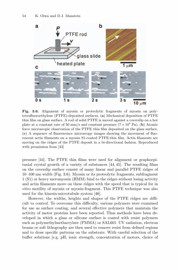
Fig. 3.6. Alignment of myosin or proteolytic fragments of myosin on poly-tetrafluoroethylene (PTFE)-deposited surfaces. (a) Mechanical deposition of PTFEthin film on glass surface. A rod of solid PTFE is moved against a coverslip on a hotplate at a constant rate of 50 mm/s and constant pressure (7× 10⁴ Pa). (b) Atomicforce microscopic observation of the PTFE thin film deposited on the glass surface.(c) A sequence of fluorescence microscopy images showing the movement of fluo-rescent actin filaments on a myosin S1-coated PTFE-thin film. Actin filaments aremoving on the ridges of the PTFE deposit in a bi-directional fashion. Reproducedwith permission from [43]
pressure [44]. The PTFE thin films were used for alignment or graphoepi-taxial crystal growth of a variety of substances [44, 45]. The resulting filmson the coverslip surface consist of many linear and parallel PTFE ridges of10–100 nm width (Fig. 3.6). Myosin or its proteolytic fragments, subfragment1 (S1) or heavy meromyosin (HMM) bind to the ridges without losing activityand actin filaments move on these ridges with the speed that is typical for invitro motility of myosin or myosin-fragment. This PTFE technique was alsoused for the kinesin-microtubule system [46].
However, the widths, heights and shapes of the PTFE ridges are diffi-cult to control. To overcome this difficulty, various polymers were examinedfor use as surface coating, and several effective polymers that maintain theactivity of motor proteins have been reported. Thus methods have been de-veloped in which a glass or silicone surface is coated with resist polymerssuch as polymethylmethacrylate (PMMA) or SAL601. UV radiation, electronbeams or soft lithography are then used to remove resist from defined regionsand to draw specific patterns on the substrate. With careful selection of thebuffer solutions [e.g. pH, ionic strength, concentration of motors, choice of
3 How Linear Motor Proteins Work 55
blocking substances such as casein and bovine serum albumin (BSA) and/ordetergents], motility can be restricted either to the unexposed, resist polymersurface or to the exposed underlying substrate.
PMMA was the first resist polymer found to be useful for immobiliz-ing myosin molecules while retaining their abilities to support the move-ment of actin [42]. Patterned surfaces were prepared by photolithographywith PMMA-coated glass coverslip. Various patterns of tracks of PMMA werefabricated on coverslips, and HMM was introduced and immobilized on thepatterns. Fluorescent actin filaments were then added in the presence of ATP.Their movements were confined to the PMMA tracks (Fig. 3.7). Through thestudy of the behavior of actin filaments moving in PMMA tracks, we foundthat the probability of an actin filament making a U-turn is low within atrack of a few micrometers width. In addition, actin filaments often movedalong the edges of the tracks when they approached the edge at low anglesinstead of escaping from the tracks. Thus, simple patterns can effectively biasthe movement of actin filaments, confining them to unidirectional movement(Fig. 3.7c) [47].
In the experiments described above, the PMMA tracks are raised abovethe surrounding glass surface. This leads to actin filaments running off thetracks and their number gradually decreasing over time. Given the potentialapplications of this system, it is thus necessary to develop a way to restrictthe movement of filaments to one dimension along linear tracks for extendedperiods of time. Restricting kinesin-driven movement of microtubules alonglinear tracks was achieved by using micrometer-scaled grooves lithographi-cally fabricated on glass surfaces [48–50]. In the presence of detergent, kinesinselectively adsorbed onto a glass surface from which the photoresist polymerhas been removed, not on the photoresist polymer itself [50]. The tracks thushave a reversed geometry as compared with those used previously i.e. theywere channels bordered by walls of the resist material. Microtubules rarelyclimbed up the walls and moved away from the track. Therefore this methodallowed us to limit the kinesin-driven movement of microtubules effectivelyto one dimension along a linear track. The sidewall collisions described aboveand the subsequent guidance of microtubules along the sidewall were wellcharacterized by [49]. Similar nano-structured surfaces were also used for theactomyosin system [40] although actin filaments often climbed up the wall andescaped from tracks owing to their lower flexural rigidity compared with micro-tubules. This limitation has been overcome by shaping the surface morphologywith nanometer precision, which forces the filaments to move exclusively onthe tracks [51].
While it is possible to use chemical and topographical patterning to guideprotein filaments and restrict their movement to particular tracks, it is moredifficult to control the direction of movement along the track. The difficultyarises because the orientation in which motors bind to a uniform surface isnot well controlled. The conversion of bidirectional movement into unidirec-tional movement along the linear tracks was finally accomplished by simply

56 K. Oiwa and D.J. Manstein
a
c
b
Fig. 3.7. (a) Atomic force micrograph of triple concentric circular PMMA tracks.(b) Fluorescence microscope images of actin filaments moving on PMMA trackscoated with myosin HMM molecules. The superpositioning of image at different timepoints shows that the movement of actin filaments is restricted to the tracks. (c)Extraction of unidirectional movement of actin filaments on HMM-coated PMMAtracks. The first panel shows a bright-field image of circular PMMA tracks. Thefluorescence microscope images show actin filaments moving counter-clockwise alongthe tracks and being directed towards the smaller circular tracks
adding arrowhead patterns on the tracks [50]. Most microtubules entering thearrowheads against the direction in which the arrowheads points are inducedto make an 180◦ turn (Fig. 3.8). As a result, unidirectional movement is gen-erated by the rectifying action of the arrow-headed pattern. Precise analysesand design of these rectifiers has been carried out by [71]. Arrowhead rectifiershave enabled us to construct microminiaturized circulators, in which popula-tions of microtubules rotate in one direction and transport materials on themicrometer scale in a predefined fashion.
In addition to the spatial control of the movement of protein filaments,the temporal control of motor protein activity has been investigated. Rapidlychasing the buffer solution with a new one is the simplest way to controlthe activity of motor proteins. Flushing out ATP induces rapid cessationof protein filament movement. To control the concentration of ATP, photo-activatable ATP is an alternative method. Kaplan and coworkers showedthat light-induced activation of caged complexes can control the activity of

3 How Linear Motor Proteins Work 57
Fig. 3.8. Micro-fabricated circular grooves with arrowhead patterns to extractunidirectional movement from bi-directional, rotational movement of microtubules.(a) An optical microscopic image of the grooves. With this pattern, microtubulesin the outer circle are moving clockwise, while those in the inner circle are movingcounter-clockwise. (b) Schematic diagram of the arrowhead functioning as a rectifierof microtubule movement
proteins [52]. Caged nucleotides have been commonly used not only for thestudy of motor protein function [53] but also for controlling motor proteinsin nanomachine-development [54]. One promising approach to controlling theactivity of motor proteins is the development of caged proteins pioneered byG. Marriott [55, 56]. Caged heavy meromyosin was prepared by conjugat-ing the thiol reactive reagent 1-(bromomethyl)-2-nitro-4, 5-dimethoxybenzenewith the critical thiol group in the so-called SH1-helix. This treatment ren-ders the molecule inactive. It can be reactivated by a pulse of near-ultravioletlight. Following irradiation with UV light, actin filaments on HMM-coatedsurface concomitantly start to move with velocities comparable to those ofunmodified HMM [55].
On the other hand, the fast and reversible on- and off-switching of themotile activity of motor proteins needs to be investigated for the applicationof motor proteins to nanomachines. Rapid perturbation such as a tempera-ture jump can be used to control movement of protein filaments. Kato et al.,developed a temperature-pulse microscope in which an IR laser beam locallyilluminated an aggregate of metal particles bound on a surface [57]. Using thissystem, the temperature of a microscopic region of ca. 10 µm in diameters wasraised reversibly in a square-wave fashion with rise and fall times of severalms with a temperature gradient up to 2 degrees C/micrometer. Using an invitro motility assay, they showed that the motor functions can be thermallyand reversibly activated even at temperatures that are high enough to nor-mally damage the proteins. By combining directional control of movement ofprotein filaments with this temperature jump method or application of light,external electric and magnetic fields, it should be possible to control cargoloading and unloading as well as the motor protein activities.

58 K. Oiwa and D.J. Manstein
Controlling the position and orientation of motor proteins with sub-nanometer precision constitutes another key technology: motor proteins needto be placed with nanometer accuracy on a surface and their orientation con-trolled within a few degrees. Spudich and coworkers demonstrated that HMMmolecules, sterospecifically bound to a single actin filament in rigor, couldbe transferred to nitrocellulose-coated surface by addition of ATP and thattransferred HMM supported motility of actin filaments [58]. Combining thistechnique to filament-alignment techniques may provide a surface on whichmotor proteins are aligned with high spatial precisions and orientation.
Several methods for coupling motor proteins to the surface have been re-ported. Fusion motor proteins with bacterial biotin-binding proteins can bindspecifically to streptavidin-coated cargoes or surfaces. Many peptide tags fusedto expressed proteins have been commonly used to make the purifications easy.Some of these tags were used to couple the proteins to surfaces coated withthe complementary ligand or antibodies [59–61].
3.9 Conclusions and Perspectives
Here, we have described the basic properties of motor proteins and how mole-cular biological techniques can be used to generate recombinant motors withwell defined properties. The alignment of motor proteins and cytoskeletal fil-aments while maintaining their functions has been achieved by the use ofnano- and micro-fabrication techniques. The methods described here are use-ful for establishing micrometer- or nanometer-scale arrays of motor proteinsand filaments, and straightforward in their application. The use of motor pro-teins in nanometric actuators is moving a step closer towards realization. Thegeneration of backwards- and forwards-moving motors that display increasedthermal stability, optimized kinetic properties, and tight regulation by exter-nal signals will play an important part in the integration of biomolecules intonanotechnological devices.
The mechanochemical coupling in myosin, as described here, is a para-digm for linear motor proteins in general and suggests that the activity ofthese nanomachines can be mediated or regulated by divers mechanisms. Theoccurrence of myosins with lever arms of different length constitutes a simplemeans of increasing the size of the working stroke and thereby the veloc-ity [23]. Similarly, the angle through which the lever arm swings affects thesize of the working stroke and velocity. It has been shown that the lever armof class I myosins swings though a ∼30◦ larger angle than in conventionalmyosin [34]. Fine-tuning of the rate of ATP turnover provides another wayto modulate the velocity of motor proteins. This can be done by changingthe rate of the ATP hydrolysis step or by modification of the rate of productrelease [62]. As the release of the hydrolysis products is greatly accelerated byactin-binding, modulation of the interaction with actin provides one meansto affect motor function. In the case of some unconventional myosins, phos-phorylation of a so-called “TEDS-residue” is required for normal coupling

3 How Linear Motor Proteins Work 59
between the actin and nucleotide bindings sites [63–65]. The negative chargeintroduced by the phosphate group stabilizes the rigor complex by reducingthe dissociation rate constant more than 30-fold. Product inhibition by ADPprovides another means to reduce the velocity of the motor protein. Mg2+-ions, which act more like catalysts during the ATPase cycle, can affect therate of ADP-release. For class-I and class-V myosins, it has been shown thatchanges in the concentration of free Mg2+-ions within the physiological rangeaffect velocity [63,66]. Motor activity can also be modulated by changes in thestiffness of the lever arm. The Ca2+-ion dependent binding of light chains caninduce such changes. Direct mechanical coupling between the heads of kinesinor myosin heavy chain dimers provides a further way to modulate motor activ-ity and, with appropriate tuning of the hydrolysis and product release steps,can play a key role in the generation of processive motors and the directionalmovement of motor proteins in the absence of a stiff lever arm [67–69].
Acknowledgements
We thank E. Mandelkow and A. Marx for providing Fig. 3.1b. The work wassupported by Special Coordination Funds for Promoting Science and Tech-nology, the Ministry of Education, Culture, Sports, Science and Technology(K.O.); Fond der Chemischen Industrie and DFG grants MA1081/5-3 andMA1081/6-1 (D.J.M.).
References
1. R. D. Vale (2000). AAA proteins. Lords of the ring. J Cell Biol, 150, pp. 13–20.2. L. M. DiBella and S. M. King (2001). Dynein motors of the Chlamydomonas
flagellum. Int Rev Cytol, 210, pp. 227–268.3. I. Milisav (1998). Dynein and dynein-related genes. Cell Motil Cytoskeleton, 39,
pp. 261–272.4. M. P. Koonce and M. Samso (2004). Of rings and levers: the dynein motor comes
of age. Trends Cell Biol, 14, pp. 612–619.5. D. J. Asai and M. P. Koonce (2001). The dynein heavy chain: structure,
mechanics and evolution. Trends Cell Biol, 11, pp. 196–202.6. K. Oiwa and H. Sakakibara (2005). Recent progress in dynein structure and
mechanism. Curr Opin Cell Biol, 17, pp. 98–103.7. M. A. Geeves, R. Fedorov, and D. J. Manstein (2005). Molecular mechanism of
actomyosin-based motility. Cell Mol Life Sci, 62, pp. 1462–1477.8. S. A. Burgess, M. L. Walker, H. Sakakibara, P. J. Knight, and K. Oiwa (2003).
Dynein structure and power stroke. Nature, 421, pp. 715–718.9. F. Kozielski, S. Sack, A. Marx, M. Thormahlen, E. Schonbrunn, V. Biou,
A. Thompson, E. M. Mandelkow, and E. Mandelkow (1997). The crystal struc-ture of dimeric kinesin and implications for microtubule-dependent motility.Cell, 91, pp. 985–994.

60 K. Oiwa and D.J. Manstein
10. F. J. Kull, E. P. Sablin, R. Lau, R. J. Fletterick, and R. D. Vale (1996). Crystalstructure of the kinesin motor domain reveals a structural similarity to myosin.Nature, 380, pp. 550–555.
11. I. Rayment, W. R. Rypniewski, K. Schmidt-Base, R. Smith, D. R. Tomchick,M. M. Benning, D. A. Winkelmann, G. Wesenberg, and H. M. Holden (1993).Three-dimensional structure of myosin subfragment-1: a molecular motor.Science, 261, pp. 50–58.
12. R. S. Goody and W. Hofmann-Goody (2002). Exchange factors, effectors, GAPsand motor proteins: common thermodynamic and kinetic principles for differentfunctions. Eur Biophys J, 31, pp. 268–274.
13. R. D. Vale (1996). Switches, latches, and amplifiers: common themes of G pro-teins and molecular motors. J Cell Biol, 135, pp. 291–302.
14. M. Anson, M. A. Geeves, S. E. Kurzawa, and D. J. Manstein (1996). Myosinmotors with artificial lever arms. EMBO J, 15, pp. 6069–6074.
15. T. Q. Uyeda, P. D. Abramson, and J. A. Spudich (1996). The neck region ofthe myosin motor domain acts as a lever arm to generate movement. Proc NatlAcad Sci USA, 93, pp. 4459–4464.
16. P. B. Conibear, C. R. Bagshaw, P. G. Fajer, M. Kovacs, and A. Malnasi-Csizmadia (2003). Myosin cleft movement and its coupling to actomyosin dis-sociation. Nat Struct Biol, 10, pp. 831–835.
17. P. D. Coureux, A. L. Wells, J. Menetrey, C. M. Yengo, C. A. Morris, H. L.Sweeney, and A. Houdusse (2003). A structural state of the myosin V motorwithout bound nucleotide. Nature, 425, pp. 419–423.
18. T. F. Reubold, S. Eschenburg, A. Becker, F. J. Kull, and D. J. Manstein (2003).A structural model for actin-induced nucleotide release in myosin. Nat StructBiol, 10, pp. 826–830.
19. K. C. Holmes, I. Angert, F. J. Kull, W. Jahn, and R. R. Schroder (2003).Electron cryo-microscopy shows how strong binding of myosin to actin releasesnucleotide. Nature, 425, pp. 423–427.
20. H. Brzeska, T. J. Lynch, and E. D. Korn (1988). Localization of the actin-binding sites of Acanthamoeba myosin IB and effect of limited proteolysis onits actin-activated Mg2+-ATPase activity. J Biol Chem, 263, pp. 427–435.
21. M. A. Geeves and P. B. Conibear (1995). The role of three-state docking ofmyosin S1 with actin in force generation. Biophys J, 68, pp. 194S–199S; discus-sion 199S–201S.
22. K. Ito, T. Kashiyama, K. Shimada, A. Yamaguchi, J. Awata, Y. Hachikubo,D. J. Manstein, and K. Yamamoto (2003). Recombinant motor domain con-structs of Chara corallina myosin display fast motility and high ATPase activity.Biochem Biophys Res Commun, 312, pp. 958–964.
23. C. Ruff, M. Furch, B. Brenner, D. J. Manstein, and E. Meyhofer (2001). Single-molecule tracking of myosins with genetically engineered amplifier domains. NatStruct Biol, 8, pp. 226–229.
24. M. Tominaga, H. Kojima, E. Yokota, H. Orii, R. Nakamori, E. Katayama,M. Anson, T. Shimmen, and K. Oiwa (2003). Higher plant myosin XI movesprocessively on actin with 35 nm steps at high velocity. EMBO J, 22, pp. 1263–1272.
25. S. Higashi-Fujime, R. Ishikawa, H. Iwasawa, O. Kagami, E. Kurimoto, K.Kohama, and T. Hozumi (1995). The fastest actin-based motor protein fromthe green algae, Chara, and its distinct mode of interaction with actin. FEBSLett, 375, pp. 151–154.

3 How Linear Motor Proteins Work 61
26. R. A. Walker (1995). ncd and kinesin motor domains interact with both alpha-and beta-tubulin. Proc Natl Acad Sci USA, 92, pp. 5960–5964.
27. S. A. Endow, S. J. Kang, L. L. Satterwhite, M. D. Rose, V. P. Skeen, andE. D. Salmon (1994). Yeast Kar3 is a minus-end microtubule motor proteinthat destabilizes microtubules preferentially at the minus ends. EMBO J, 13,pp. 2708–2713.
28. J. Menetrey, A. Bahloul, A. L. Wells, C. M. Yengo, C. A. Morris, H. L. Sweeney,and A. Houdusse (2005). The structure of the myosin VI motor reveals themechanism of directionality reversal. Nature, 435, pp. 779–785.
29. A. L. Wells, A. W. Lin, L. Q. Chen, D. Safer, S. M. Cain, T. Hasson, B. O.Carragher, R. A. Milligan, and H. L. Sweeney (1999). Myosin VI is an actin-based motor that moves backwards. Nature, 401, pp. 505–508.
30. A. Inoue, J. Saito, R. Ikebe, and M. Ikebe (2002). Myosin IXb is a single-headedminus-end-directed processive motor. Nat Cell Biol, 4, pp. 302–306.
31. M. A. Geeves, and K. C. Holmes (1999). Structural mechanism of muscle con-traction. Ann Rev Biochem, 68, pp. 687–728.
32. G. Tsiavaliaris, S. Fujita-Becker, and D. J. Manstein (2004). Molecular engi-neering of a backwards-moving myosin motor. Nature, 427, pp. 558–561.
33. W. Kliche, S. Fujita-Becker, M. Kollmar, D. J. Manstein, and F. J. Kull (2001).Structure of a genetically engineered molecular motor. EMBO J, 20, pp. 40–46.
34. M. Kollmar, U. Durrwang, W. Kliche, D. J. Manstein, and F. J. Kull (2002).Crystal structure of the motor domain of a class-I myosin. EMBO J, 21,pp. 2517–2525.
35. B. Prakash, L. Renault, G. J. Praefcke, C. Herrmann, and A. Wittinghofer(2000). Triphosphate structure of guanylate-binding protein 1 and implicationsfor nucleotide binding and GTPase mechanism. EMBO J, 19, pp. 4555–4564.
36. S. J. Kron and J. A. Spudich (1986). Fluorescent actin filaments move on myosinfixed to a glass surface. Proc Natl Acad Sci USA, 83, pp. 6272–6276.
37. L. Limberis and R. J. Stewart (2000). Toward kinesin-powered microdevices.Nanotechnol, 11, pp. 47–51.
38. R. Stracke, K. J. Bohm, J. Burgold, H. J. Schacht, and E. Unger (2000). Physicaland technical parameters determining the functioning of a kinesin-based cell-freemotor system. Nanotechnol, 11, pp. 52–56.
39. K. J. Bohm, R. Stracke, P. Muhlig, and E. Unger (2001). Motor protein-drivenunidirectional transport of micrometer-sized cargoes across isopolar microtubulearrays. Nanotechnol, 12, pp. 238–244.
40. R. Bunk, J. Klinth, L. Montelius, I. A. Nicholls, P. Omling, S. Tagerud, andA. Mansson (2003). Actomyosin motility on nanostructured surfaces. BiochemBiophys Res Commun, 301, pp. 783–788.
41. D. V. Nicolau, H. Suzuki, S. Mashiko, T. Taguchi, and S. Yoshikawa (1999).Actin motion on microlithographically functionalized myosin surfaces andtracks. Biophys J, 77, pp. 1126–1134.
42. H. Suzuki, A. Yamada, K. Oiwa, H. Nakayama, and S. Mashiko (1997). Con-trol of actin moving trajectory by patterned poly(methylmethacrylate) tracks.Biophys J, 72, pp. 1997–2001.
43. H. Suzuki, K. Oiwa, A. Yamada, H. Sakakibara, H. Nakayama, and S. Mashiko(1995). Linear Arrangement of Motor Protein on a Mechanically DepositedFluoropolymer Thin Film. Jpn J Appl Phys, 34, pp. 3937–3941.

62 K. Oiwa and D.J. Manstein
44. J. C. Wittmann and P. Smith (1991). Highly oriented thin-films ofpoly(tetrafluoroethylene) as a substrate for oriented growth of materials. Nature,352, pp. 414–417.
45. D. Fenwick, P. Smith, and J. C. Wittmann (1996). Epitaxial and graphoepitaxialgrowth of materials on highly orientated PTFE substrates. J Mat Science, 31,pp. 128–131.
46. J. R. Dennis, J. Howard, and V. Vogel (1999). Molecular shuttles: directedmotion of microtubules slang nanoscale kinesin tracks. Nanotechnol, 10, pp. 232–236.
47. K. Oiwa, D. M. Jameson, J. C. Croney, C. T. Davis, J. F. Eccleston, andM. Anson (2003). The 2′-O- and 3′-O-Cy3-EDA-ATP(ADP) complexes withmyosin subfragment-1 are spectroscopically distinct. Biophys J, 84, pp. 634–642.
48. J. Clemmens, H. Hess, J. Howard, and V. Vogel (2003a). Analysis of micro-tubule guidance in open microfabricated channels coated with the motor proteinkinesin. Langmuir, 19, pp. 1738–1744.
49. J. Clemmens, H. Hess, R. Lipscomb, Y. Hanein, K. F. Bohringer, C. M. Matzke,G. D. Bachand, B. C. Bunker, and V. Vogel (2003b). Mechanisms of microtubuleguiding on microfabricated kinesin-coated surfaces: Chemical and topographicsurface patterns. Langmuir, 19, pp. 10967–10974.
50. Y. Hiratsuka, T. Tada, K. Oiwa, T. Kanayama, and T. Q. Uyeda (2001). Con-trolling the direction of kinesin-driven microtubule movements along microlitho-graphic tracks. Biophys J, 81, pp. 1555–1561.
51. R. Bunk, M. Sundberg, A. Mansson, I. A. Nicholls, P. Omling, S. Tagerud, andL. Montelius (2005). Guiding motor-propelled molecules with nanoscale preci-sion through silanized bi-channel structures. Nanotechnol, 16, pp. 710–717.
52. J. H. Kaplan, B. Forbush, 3rd, and J. F. Hoffman (1978). Rapid photolyticrelease of adenosine 5′-triphosphate from a protected analogue: utilization bythe Na:K pump of human red blood cell ghosts. Biochemistry, 17, pp. 1929–1935.
53. J. A. McCray, L. Herbette, T. Kihara, and D. R. Trentham (1980). A newapproach to time-resolved studies of ATP-requiring biological systems; laserflash photolysis of caged ATP. Proc Natl Acad Sci USA, 77, pp. 7237–7241.
54. H. Hess, J. Clemmens, D. Qin, J. Howard, and V. Vogel (2001). Light-controlledmolecular shuttles made from motor proteins carrying cargo on engineered sur-faces. Nano Letters, 1, pp. 235–239.
55. G. Marriott and M. Heidecker (1996). Light-directed generation of the actin-activated ATPase activity of caged heavy meromyosin. Biochemistry, 35,pp. 3170–3174.
56. G. Marriott, P. Roy, and K. Jacobson (2003). Preparation and light-directedactivation of caged proteins. Methods Enzymol, 360, pp. 274–288.
57. H. Kato, T. Nishizaka, T. Iga, K. Kinosita, Jr., and S. Ishiwata (1999). Imag-ing of thermal activation of actomyosin motors. Proc Natl Acad Sci USA, 96,pp. 9602–9606.
58. Y. Y. Toyoshima, C. Toyoshima, and J. A. Spudich (1989). Bidirectional move-ment of actin filaments along tracks of myosin heads. Nature, 341, pp. 154–156.
59. Y. Inoue, Y. Y. Toyoshima, A. H. Iwane, S. Morimoto, H. Higuchi, and T.Yanagida (1997). Movements of truncated kinesin fragments with a short or anartificial flexible neck. Proc Natl Acad Sci USA, 94, pp. 7275–7280.

3 How Linear Motor Proteins Work 63
60. S. Itakura, H. Yamakawa, Y. Y. Toyoshima, A. Ishijima, T. Kojima, Y. Harada,T. Yanagida, T. Wakabayashi, and K. Sutoh (1993). Force-generating domainof myosin motor. Biochem Biophys Res Commun, 196, pp. 1504–1510.
61. A. H. Iwane, K. Kitamura, M. Tokunaga, and T. Yanagida (1997). Myosinsubfragment-1 is fully equipped with factors essential for motor function.Biochem Biophys Res Commun, 230, pp. 76–80.
62. R. W. Lymn and E. W. Taylor (1970). Transient state phosphate production inthe hydrolysis of nucleoside triphosphates by myosin. Biochemistry, 9, pp. 2975–2983.
63. S. Fujita-Becker, U. Durrwang, M. Erent, R. J. Clark, M. A. Geeves, and D.J. Manstein (2005). Changes in Mg2+ ion concentration and heavy chain phos-phorylation regulate the motor activity of a class I myosin. J Biol Chem, 280,pp. 6064–6071.
64. E. M. Ostap, T. Lin, S. S. Rosenfeld, and N. Tang (2002). Mechanism of regu-lation of Acanthamoeba myosin-IC by heavy-chain phosphorylation. Biochem-istry, 41, pp. 12450–12456.
65. Z. Y. Wang, F. Wang, J. R. Sellers, E. D. Korn, and J. A. Hammer, 3rd (1998).Analysis of the regulatory phosphorylation site in Acanthamoeba myosin IC byusing site-directed mutagenesis. Proc Natl Acad Sci USA, 95, pp. 15200–15205.
66. S. S. Rosenfeld, A. Houdusse, and H. L. Sweeney (2005). Magnesium regulatesADP dissociation from myosin V. J Biol Chem, 280, pp. 6072–6079.
67. N. J. Carter and R. A. Cross (2005). Mechanics of the kinesin step. Nature, 435,pp. 308–12.
68. P. B. Conibear and M. A. Geeves (1998). Cooperativity between the two headsof rabbit skeletal muscle heavy meromyosin in binding to actin. Biophys J, 75,pp. 926–937.
69. M. Nyitrai and M. A. Geeves (2004). Adenosine diphosphate and strain sensitiv-ity in myosin motors. Philos Trans R Soc Lond B Biol Sci, 359, pp. 1867–1877.
70. D. C. Turner, C. Chang, K. Fang, S. L. Brandow, and D. B. Murphy (1995).Selective adhesion of functional microtubules to patterned silane surfaces. Bio-phys. J, 69, pp. 2782–2789.
71. M. G. L. van den Heuvel, C. T. Butcher, R. M. M. Smeets, S. Diez, and C. Dekker(2005). High rectifying efficiencies of microtubule motility on kinesin-coated goldnanostructures. Nano Letters, 5, pp. 1117–1122.
