3. ethernet two nodes transmit at the same time 1 node detect there has been a collision 2 nodes...
TRANSCRIPT
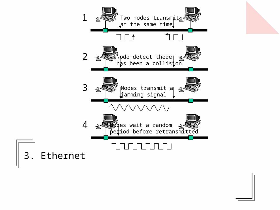
3. Ethernet
Two nodes transmitat the same time
1
Node detect therehas been a collision
2
Nodes transmit ajamming signal
3
Nodes wait a randomperiod before retransmitted
4

3.1 Ethernet (Advantages/Problems)
Advantages:Ethernet networks are easy to plan and cheap to install.Ethernet network components, such as network cards and connectors, are cheap and well supported.Uses coaxial, fibre or twisted-pair cables.It is a well-proven technology, which is fairly robust and reliable.It is simple to add and delete computers on the network.It is supported by most software and hardware systems.Available as 10Mbps (10BASE), 100Mbps (100BASE) and 1Gbps (1000BASE). Dual-speed networks can be used, such as mixed 10Mbps/100Mbps networks. Network hub negotiates the required speed.Easy upgrade for different network speed. A dual-speed network can be run, and gradually upgraded.Standardised as 1EEE 802.3.
Advantages:Ethernet networks are easy to plan and cheap to install.Ethernet network components, such as network cards and connectors, are cheap and well supported.Uses coaxial, fibre or twisted-pair cables.It is a well-proven technology, which is fairly robust and reliable.It is simple to add and delete computers on the network.It is supported by most software and hardware systems.Available as 10Mbps (10BASE), 100Mbps (100BASE) and 1Gbps (1000BASE). Dual-speed networks can be used, such as mixed 10Mbps/100Mbps networks. Network hub negotiates the required speed.Easy upgrade for different network speed. A dual-speed network can be run, and gradually upgraded.Standardised as 1EEE 802.3.
Common bus
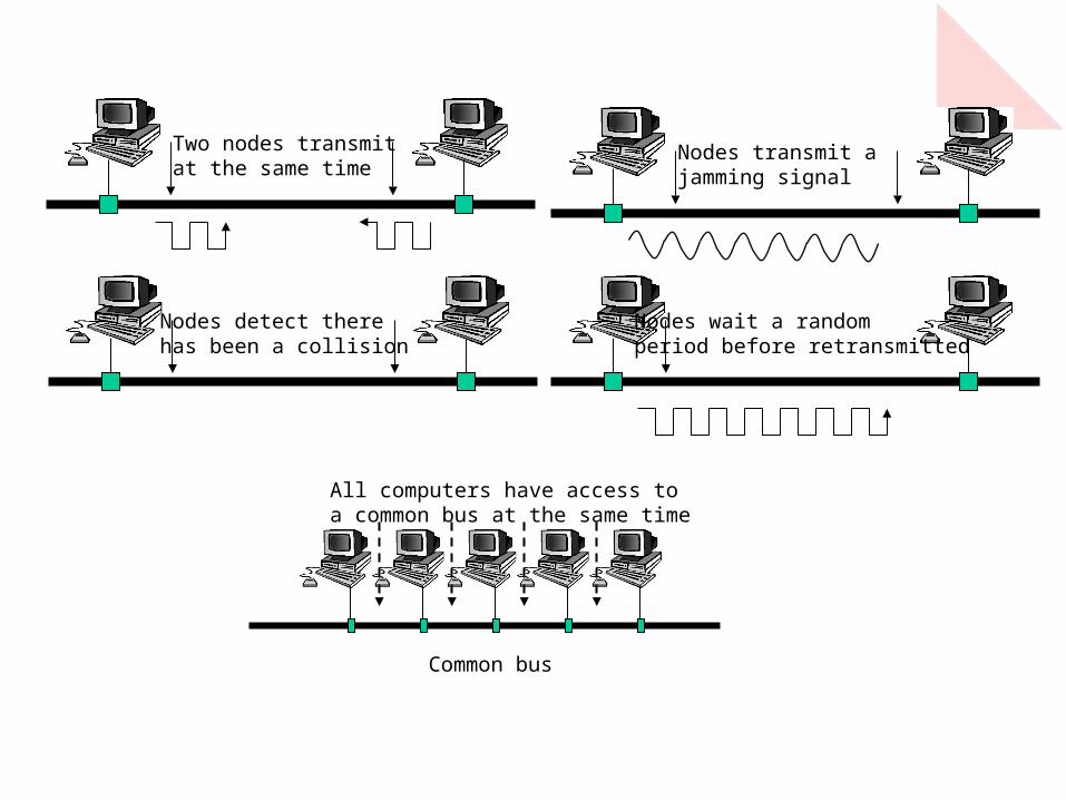
All computers have access toa common bus at the same time
Ethernet hub
Problem:A major problem with Ethernet is that, because computers must contend to get access to the network, there is no guarantee that they will get access within a given time. This contention also causes problems when two computers try to communicate at the same time, they must both back off and no data can be
transmitted.

3.2 CSMA/CDCSMA/CDEthernet uses carrier sense, multiple access with collision detection (CSMA/CD). Nodes monitor the bus (or Ether) to determine if it is busy. A node wishing to send data waits for an idle condition then transmits its message. Collisions can occur when two nodes transmit at the same time, thus nodes must monitor the cable when they transmit. When a collision occurs, both nodes stop transmitting frames and transmit a jamming signal. This informs all nodes on the network that a collision has occurred. Each of the nodes involved in the collision then waits a random period of time before attempting a re-transmission. As each node has a random delay time then there can be a prioritisation of the
nodes on the network.
CSMA/CDEthernet uses carrier sense, multiple access with collision detection (CSMA/CD). Nodes monitor the bus (or Ether) to determine if it is busy. A node wishing to send data waits for an idle condition then transmits its message. Collisions can occur when two nodes transmit at the same time, thus nodes must monitor the cable when they transmit. When a collision occurs, both nodes stop transmitting frames and transmit a jamming signal. This informs all nodes on the network that a collision has occurred. Each of the nodes involved in the collision then waits a random period of time before attempting a re-transmission. As each node has a random delay time then there can be a prioritisation of the
nodes on the network.
1
2
3
4
Two nodes transmitat the same time
Nodes detect therehas been a collision
Nodes transmit ajamming signal
Nodes wait a randomperiod before retransmitted
Common bus
All computers have access toa common bus at the same time
Nodes transmit ajamming signal
Nodes wait a randomperiod before retransmitted
Two nodes transmitat the same time
Nodes detect therehas been a collision
Common bus
All computers have access toa common bus at the same time
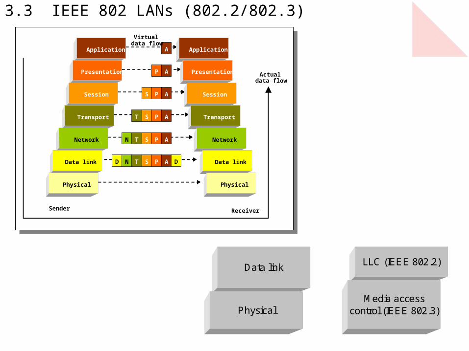
3.3 IEEE 802 LANs (802.2/802.3)
Application
Presentation
Session
Transport
Network
Data link
Physical
Application
Presentation
Session
Transport
Network
Data link
Physical
D N T S P A D
N T S P A
T S P A
S P A
P A
A
Sender Receiver
Virtualdata flow
Actualdata flow
LLC (IEEE 802.2)Data link
PhysicalMedia access
control (IEEE 802.3)

3.4 IEEE 802.3 data frame 7 bytes 1 byte 6 bytes 6 bytes
46 to 1500 bytes
4 bytes 96 bits
10101...0101010 10101011
2 bytes
Delay FCS Length Source address
Destination address
Start delimiter Preamble
Data field (Logical Link Control)
Others:4 bytes for the CRC (32 bits) and 2 bytes for the LLC length (16 bits). The LLC part may be up to 1500 bytes long. The preamble and delay components define the start and end of the frame. The initial preamble and start delimiter are, in total, 8 bytes long and the delay component is a minimum of 96 bytes long.
Others:4 bytes for the CRC (32 bits) and 2 bytes for the LLC length (16 bits). The LLC part may be up to 1500 bytes long. The preamble and delay components define the start and end of the frame. The initial preamble and start delimiter are, in total, 8 bytes long and the delay component is a minimum of 96 bytes long.
Preamble (seven bytes) precedes the Ethernet 802.3 frame. Each byte of the preamble has a fixed binary pattern of 10101010 and each node on the network uses it to synchronise their clock and transmission timings. It also informs nodes that a frame is to be sent and for them to check the destination address in the frame.Start delimiter field (SDF) is a single byte (or octet) of 10101011. It follows the preamble and identifies that there is a valid frame being transmitted.
Preamble (seven bytes) precedes the Ethernet 802.3 frame. Each byte of the preamble has a fixed binary pattern of 10101010 and each node on the network uses it to synchronise their clock and transmission timings. It also informs nodes that a frame is to be sent and for them to check the destination address in the frame.Start delimiter field (SDF) is a single byte (or octet) of 10101011. It follows the preamble and identifies that there is a valid frame being transmitted.
Delay. The end of the frame there is a 96-bit delay period, which provides the minimum delay between two frames. This slot time delay allows for the worst-case network propagation delay.
Delay. The end of the frame there is a 96-bit delay period, which provides the minimum delay between two frames. This slot time delay allows for the worst-case network propagation delay.
Source/destination addresses (2 or 6 bytes, Most Ethernet systems use a 48-bit MAC address for the sending and receiving node. Each Ethernet node has a unique MAC address, which is normally defined as hexadecimal digits, such as:
4C-31-22-10-F1-32 (4C31 : 2210: F132)
A 48-bit address field allows 248 different addresses (or approximately 281474976710000 different addresses).
IP TCP HTTP DataE.g.

3.5 IEEE 802.3 frame delays and timings
nssT 1001010
1
ratebit
16
msnsT 2.11008124150026617max
snsT 067.010081244626617min
sspeed
distT m 33.3
105.1
5008500
33.33100
33.3ed transmittbits ofNumber 500
ns
s
T
T
bit
m
Maximum and minimum time for a frame:
Time to transmit a single bit (for 10Mbps):
Time to propagate 500m (assuming half the speed of light):
Assuming a segment length of 500m, number of bits transmitted before a collision is detected:
500m
Speed = 1.5108
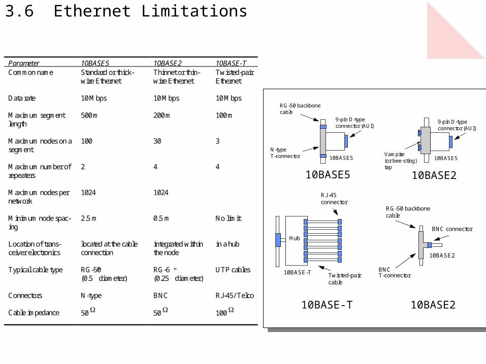
3.6 Ethernet Limitations
Parameter 10BASE5 10BASE2 10BASE-T Common name
Standard or thick-wire Ethernet
Thinnet or thin-wire Ethernet
Twisted-pair Ethernet
Data rate
10 Mbps 10 Mbps 10 Mbps
Maximum segment length
500 m 200 m 100 m
Maximum nodes on a segment
100 30 3
Maximum number of repeaters
2 4 4
Maximum nodes per network
1024 1024
Minimum node spac-ing
2.5 m 0.5 m No limit
Location of trans-ceiver electronics
located at the cable connection
integrated within the node
in a hub
Typical cable type
RG-50 (0.5” diameter)
RG-6 (0.25” diameter)
UTP cables
Connectors
N-type BNC RJ-45/ Telco
Cable impedance
50 50 100
10BASE510BASE5
RG-50 backbonecable
N-typeT-connector
9-pin D-typeconnector (AUI)
9-pin D-typeconnector (AUI)
Vampire(or bee-sting)tap
BNCT-connector
BNC connector
10BASE2
10BASE-T
Hub
RG-50 backbonecable
Twisted-paircable
RJ-45connector
10BASE5 10BASE2
10BASE210BASE-T
3.7 Ethernet types
• Standard, or thick-wire, Ethernet (10BASE5).• Thinnet, or thin-wire Ethernet, or Cheapernet (10BASE2).• Twisted-pair Ethernet (10BASE-T).• Optical fibre Ethernet (10BASE-FL).• Fast Ethernet (100BASE-TX and 100VG-Any LAN).• Gigabit Ethernet (1000BASE-SX, 1000BASE-T, 1000BASE-LX and 1000BASE-CX).
New standards relating to 100Mbps Ethernet are now becoming popular:
• 100BASE-TX (twisted-pair) – which uses 100Mbps over two pairs of Cat-5 UTP cable or two pairs of Type 1 STP cable.
• 100BASE-T4 (twisted-pair) – which is the physical layer standard for 100Mbps over Cat-3, Cat-4 or Cat-5 UTP.
• 100VG-AnyLAN (twisted-pair) – which uses 100Mbps over two pairs of Cat-5 UTP cable or two pairs of Type 1 STP cable.
• 100BASE-FX (fibre-optic cable) – which is the physical layer standard for 100Mbps over fibre-optic cables.

3.8 Ethernet hubs
10BASE-Thub
Ethernet backbone

3.9 Switches and switching hubs
LocalserverLocal
printer
Workgroupnodes
Desktop switch
LocalserverLocal
printer
Workgroupnodes
Desktop switch
Main server
Network backbone connection
Segment switches allow simultaneous communication between any client and
any server.
Segment switches allow simultaneous communication between any client and
any server.
Store-and-forward switchesminimise collisions and theycan store Ethernet frames and retransmit them when segment is quiet.
Store-and-forward switchesminimise collisions and theycan store Ethernet frames and retransmit them when segment is quiet.

3.10 802.2 and SNAP
Idle Preamble
+0.7 V
0.1 s
1 0 1 0 1
–0.7 V
Idle
PLS
PMA
MDI
MAC
Medium
AUI
MAU
PreambleStart
delimiterDestination
addressSourceaddress
Logicallink control
FCS Delay
7 bytes 1 byte 6 bytes 6 bytes 46 to 1500 bytes 4 bytes 96 bytes
10101...0101010
10101011
Length
2 bytes
Destinationservice access point (DSAP)
Sourceservice access point (DSAP)
Controlfield
DATA
1/2 bytes1 byte1 byte
PreambleStart
delimiterDestination
addressSourceaddress
Logicallink control
FCS Delay
7 bytes 1 byte 6 bytes 6 bytes 46 to 1500 bytes 4 bytes 96 bytes
10101...0101010
10101011
Length
2 bytes
1010 1010 DATA
3 bytes
1010 1010 0000 0011Organization
IDEtherType
2 bytes
SNAP header
802.2
SNAP
1 2 3 4 5 6 7 8 9 10 11 12 13 14 15 16
DSAP
1 byte 1 byte 1/2 byte(s) 1 byte
SSAP Control Data
0Send seq. no
(0-127)P 0
Receive seq. no(0-127)
Informationframe
1 S P 0Receive seq. no
(0-127)Supervisoryframe0
RR, RNRor REJ

3.11 100BASE-4TNode Hub
Tx Rx
Rx Tx
Tx Rx
Rx Tx
Pair 1
Pair 2
Pair 3
Pair 4
Compatible with10BASE
Input Output0000 0000 -+0 0-+0000 0001 0-+ -+00000 0010 0-+ 0-+0000 0011 0-+ +0-
+
0
-
8B6T
• Cat-3 transmission (if possible, use Cat-5 with 100BASE-T). 100BASE-T uses only 2 pairs.
• Zero DC level:• DC Wander (transformer coupled).• Reduced power transmission.
• Reduced frequency content.• Contention-based (as 10BASE),
thus maximum through is only about 50Mbps.

3.12 100VG-AnyLAN
• Non contention-based. Uses Round-Robin Arbitration Method known as demand priority access method (DPAM). Maximum through put is 96Mbps.
• Nodes are connected to a hub & input ports are scanned for pending requests.A request has an in-built high or normal priority status. High: real time data; Normal:non-real-time data.
• Ethernet & Token Ring Network compatible. Allows up to seven levels of hubs (One root & six cascaded hubs). This allows a number of nodes to connect to a segment. (Limited use due to non support mechanism for data after leaving hub)