2,uis-(+rtrf - skyline soaringskylinesoaring.org/docs/flight_manual_discus.pdfdiscus cs - 3- fligiit...
TRANSCRIPT

\7 FLIGHT MANUAt
2,uis-(+rtrf
:
v

orlldan a.a. Choeefi565 37 chocetl, CsfRtelr o468 / 952fax.0468 / 951-488
I{ANUA
aaJ.lplane
nTFl(!tts
Translatlon of the Czech llanual
Issue ,June 1990
ThLa rnanual lnu6t be carried on board at all tlnes
FLfGHT
for the
It refers to the sallplane
l{odel Dl Rr:rrs es
Reqlstratl,on No.
,"rr"* *o.
Manufacturer Orl1dan, a.e. Chocefi, CSFR
Olrner , .
Thls English editlon of the Dlscug cs Fltghtlilanual has been tranelated wlth care, and Lsaccurate to the best of our knowledge. However, lnall offlclal matters the origlnal Czech text lethe authoritatLve and deflnlte docuuent.
Page No.the St6tni
by

Discus CS -r/r' FLIGHT HANUAI,
Table of contents Page No.
Amendment list
1. ceneral
1. l" ceneral descriptionL.2 cockpit design and controls1.3 Airspeed indicator error curve
2.
2.L2.22,32.42.52.62.72.4
2.92.102.LL2.L2
3.
3.13.23.3
operatinq limitations !
Category of airvrorthinessPerrnitted operationsMinirnum equipmentAirspeed timitationsLoad factorsweightsLoading tableCenter of gravity range and positionsWeight and balance 1og chartLaunching hooksWeak tinks '
Tire pressureCrosswind
Emerqencv procedures
Spin recoverycanopy jettisoning and emergency exitsafety considerations
35.
l-3
2A2930
14t5161920202l232627272727
June 1990

I
I oiscus cs - L/2 - FLIGHT HANUAL I
Table of contents No.
4. Normal operatinq procedures
4.1 Daily inspectlon4.2 Pre-flight inspectJ.on4.3 Take-off4.3.1 Aerotowing4.3.2 Winch launching4.4 Free flight4.5 Low speed fllght and sta114.6 High speed flight4.7 r'lying with water ballast4.8 Cloud ftying4.9 Flying at temperatures below4.10 Restricted aerobatics4.11 Approach and landing
5. Riqqinq and de-riqqing
s. l- Rigging5.2 De-rigging5.3 storage, hangaring and towing5.4 Carlng for the saJ.lplane
Appendlx
Performance data
31353535373940434549
freezing point 495152
53565758
6.
June 1990

Dlscus CS - 2- FLIGIIT HANUAI,
Amendmqnl-Ikl(Log of Revlslons)
No. T1 tle Paqe Date
ffiAffiaI
M\.rc>,
1. Modi f l.cntton Brrll atlrr llo. 1/Dl.ncrrs CS
affected: 5/ll 07B Cli attd ttP
Cocl<p1t vetrtJ.ltr tlon 5r6Nay
199 2
d.o Rlqqlnq lever omi t,bed 54AprLl1993
3. Technlcal Note No. 360 - 13
Lllnglete optlonal use on allsarial numbers
3, 442r5455r56 l;m
fl"t

Discus CS - 3- FLIGIIT I{ANUAL
1.
r.1
Genera I
General Description
The Dlscus Cs is a slngle-seat hlgh performancesailplane ln CFRP/GFRP constructlon featuringa T-talI (with fixed horlzonbal stabillzer andelevator).
Wlnqs
The two-plece wings - each have a trl-trapezoldalplan form, swepL-back leading edge and rrtvo- atoryrialrbrakes on the upper surface. Ailerona havelnternal drlve. Water ballast tanks are lntegralcompart,ments ln the wlng D nose, total capacltyapprox. 184 llters. Wlng shells are of glassfiber/foam sandwlch wlth spar flanges of carbonfiber rovlngr and shear rrcbs of glarr flber/foaosandylch. For furtbcr Lmproveocnt of thc perform-ance, rrlntleta (optJ.on) r"y be flttcd to ihe vlngtlps.
Fuse I aqe
The pllot has a semi-recllning posltlon. Thecockplt le comfortable. A one-plece canopy hlngeeeldeways. The fuselage shell ls a pure gtiie flberlay-up without sandwich and therefore ls hlghtyenergy abaorblng. It le etlffened towards the tailwlth GPRP,/foam sandwlch webs and the front fuselagefeatures a double shell on both sides and on thebotton. The sprung undercarrlage ls retractable andls fltted wlth a wheel brake.
llorizon!aI tai lplane
The horizontal stablllzer ls bullt ln cFRp/ foansandwlch and the elevator ls a pure cFRp lay-uir.Vertical fin
Both fln and rudder are aconstruction. The lntegral water' fin has a capacity of 6.5Gal./1.43 Imp. Gal".).
TECHNICAL NOTE NO. )5O - rl
GFRP/foam sandwichbalLast tank ln the
k9 (Ltr) (I.72 U.s.
June 1994

o\
o
F)
t
o\om
o
aFozrl
oH2()H3
\
U\
Jnll\J
(
.J
\
NN
.o.o
ovtc:no
$rNdEui0rJixoroNU)
4aBAcxga
N)JJJ)!AL.b\bu
@o\f.trov()(l@lloroN .oorclNN!fN
J-
ti).4t\t-raAE6l.l
E{I3.dulol!
orotj.J:oln.'lNNUI
tNol
!dadEOq,.l0(,'rNJouo)dtnoc-rooo
Jdd.{OE.CJd-rr.t.F,-Jortorolc4{,cHq!JtE!aJ
oUrUraccEn>=4
dD{d
3lnl
r..l
gi
'1zoHt{AoFI
a€{FIFl(,zH
=
J
oq
N
EIo)no
(\CA

Discus CS - 5- FLIGHT I{ANUAL
L.2 Cockpit Desiqn and Controls
Irlodif . Bulletin llo . 1,/Discus CS 1992
Dlscus CS - 6- FLIGHT I.IANUAI,
(1)
(21
(3)
(4)
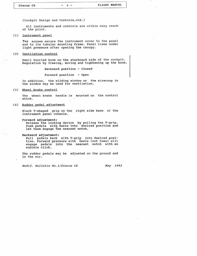
(cockpit Design and Controls,ctd. )
A11 instruments and controls are wlthin easyof the pilot.Instrument panel
Two screws secure the instrument cover to theand to its tubular mounting frame. Panel riseslight pressure after opening the canopy.
Ventilatlon control
Small knurled knob on the starboard side of theRegulation by freelng, movlng and tightening up
reach
panelunder
cockplt.the knob.
Backward posltlon - Closed
Forward posltlon - Open
In addl-tion, the sliding wlndow or the airscoop inthe window may be used for ventllation.Wheel brake controlThe wheel brake handle ls mounted on the controlstlck.Rudder pedal adiustment
Black T-shaped grip on the right side base of theinstrument panel console.
Forward adJuetrnent:Release the locking devlce by pulllng the T-grlp.Push pedals witb heela lnto deslred positlon andlet tirern engage ihe nearest notch.
Backward adJustment:Pull pedals back wlth T-grlp lnto desired posi-tion. Forward pressure with heels (not toes) w111engage pedals into the neareat notch wlth anaudible cllck.
The rudder pedals may be adJusted on the ground andin the alr.
Itodif . BulTetin No.l./Discus c.9 Nay 7992

Dlscus CS FLIGHT I.{ANUAL
(cockpit Design and controls,ctd. )
(5) Launchinq hook release handle
Yellow T-shaped handle on the left at thethe instrurnent panel console.
The winch cable (tow rope) is released bythe handle.
(6) Landinq qear operating lever
base of
pulling
Retract :
Extend :
(7) Canopv
Unlock the black handle on the right atthe seat pan support, pull back andengage l-n rear recess.
Unlock black handle, push forward andengage in rear recess
; iii-:'f,;'I -The one-piece plexiglass canopy hl"nges sideways on flushflttlngs. Take care that the cable restrainlng the opencanopy is attached.
(8) Canopy locking devl-ce
Lever control wlth red knob on the left on thecanopy frame.
Backward position .... canopy locked
To open the canopy swlng lever forward and raisecanopy.
(9) Canopv emerqencv jettisoninq device
Slidlng red knob on the right on the canopy frame.
Backward posltJ.on .... loeked
To jettison the canopy, first swlng the lockinglever on the left on the canopy frane forward, raiaecanopyfpush the red Jettlson knob on the rlght onthe l-nner skln forward and push canopy away.
June 1990
Dlscug CS -8 FLIGHT HANUAL
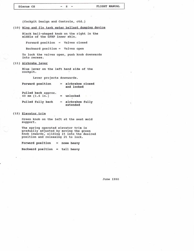
(cockpit Design and controls, ctd. )
(1,0) Wing and fin tank water ballast dunpinq devlce
Black ball-shaped knob on the right in themiddle of the GFRP lnner skin.
Forward position valves closed
Backward position = Valves open
To lock the valves open, push knob downwardslnto recess.
(11) Airbrake leverBlue lever on the left hand side of thecockplt. l
Lever projects downwards.
forrrard posltl-on airbrakes closedand locked
Pulled back approx.nn (1.6 in. ) = unlocked
Pulled fully back airbrakes fullyextended
(12) Elevatar trlnGreen knob on the left at the seat moldsupport.
The spring operated elevator trlrn isgradually adjusted by moving the greenknob inwards, sliding it into the desiredposition and releasing it to lock.
Forward posltJ-on = nose heavy
Backnard positlon tall heavy
June l-990
r- |
I Discus cs - 9 - F'LIGHT I'lAllUAL I
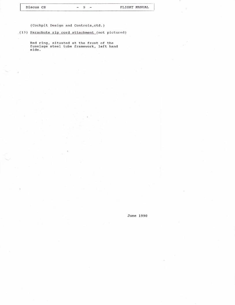
(Cockpit Design and ConLrols,ctd. )
(13) Parachute rip cord attachment (not pictured)
Red ring, situated at the front of thefuselage steel tube framework, left handside-
June 1990

Digcus CS -10- FLTGHT TTANUAL
(cockpit Design and Controls,ctd. )
Cocpit placards (operating data and miscellaneous)
Identification plate (fire proof)
.h1l)
OR
Iypo
S/il- Ycar of Prod uclion
.1, IC No:
LI.AN CHOCEN A.S.Czech Rcpublic
operatinq limitatlons
l{eak links for a:If"g,Maximum 680 daN (1499 1b)
l,tain wheer ti-up to 360 kg (794 Ib): 3.5 bar (50 psi)above 360 kg (794 Ib): 4.5 bar (ea psi)
June 1990
l.l,ax pernitted atl-up welght: s25 kg(1157 Ib)
tlax perml-tted speeds ( IAS ) knlh kt nph
Max permitted speed 25O 135 1,55in rough air 2OO l-08 1,24
Maneuvering speed 200 L08 L24on aerotow 18o 97 LLz
Automobile and wlnch launch 15o 8L 93
operatlng llnlts when fln tank le used:
Mininumgroundtemperature
oc 13.5 17 24 31 38
oF 5G 63 75 BB 1oo
Maximumabsoluteceiling
m 1500 2000 3000 4000 5000
ft 4900 6500 9800 t-31-00 l-5400

(Cockpit Design and Controlsrctd. )
Load on pllotte geat(pilot and parachute)
Maximum load 110 kq (242.s 1b)lMinimum load 70 kq ( L54.3 1b)'
Pilotts weight of less than 7O kg(154.3 lb) must be raised by using
trim ballast
t As the actual nininun or naximum seat foad.of thissailplane to which this manual refers may differfron the above typical weights, the placard in thecocpit nust show the actual treights which are al-soto be entered in the log sheet (see paqe 26).
Check llst before take-off
^ Water in fin tank?I loading charts checked?I Parachute securely fastened?I satety harness secured and tlght?I sacX rest and pedals in comfortable" position?- A1I controls and inStrumentst accessible?o Airbrakes locked after functioning
check?
^ A11 control surfaces checked with- asslstant for full and free movement
ln correct sense?. Trimer correctly set?I canopy cfosed and locked?
Aerobatlce: without water ballastthe following maneuvers are perrnitted:
a) Inside loops c) Spinsb) Stalled Turns d) Lazy Eight
Baggage conpartnent
Maximal load: 2.0 kg (4.4 lb)
June 1990

(cockpit Design and Controls,ctd. )
Cockpit controls - markinqs
gear DOWN
heavy TAIL
gear UP
heavy NOSETrirnmer - green knob
tr^- 1lPedal adjustment
left-Canopy opening
Ventilation
Yellow tow reLease handle
Airbrakes - blue handle
q/tred knobs
right-Canopy jettisoning
water ballast dumping knob
June 1990

I olscus cS - lza - FLIGHT UANUAL
(cockpit Design
Fin tank 1abel:
and Controls,ctd. )
(right side onlY)
\
II
\
I
I ' G.,5 ks/ tr -tDI +sI +-1I +3I +z
\ o'
June 1990

1".3 Airspeed indicator system errors
Errors in indicated airspeed caused by Pitot/Staticpressure ".."i. may be read off from the calibrationchart below.
Position of the Pressure r:orts:
Static pressure: Fuselage, approx' 15:T (5'9in) belowmain sp-ar cuL-out and on fuselage tail boorn' approx'Bo; iir.sin) forward of the base of the fin'
Pitot pressure: on the leading edge of the fin'
Allairspeedsshowninthismanualareindicatedairspeeds ( IAs ) as registered .
by , the airspeedindiiator. in" calibration curve is also valid forwinch launching and aerotow'
mph kt km/h
149 130 240
137 119 220
124 108 200
112 97 180
99 86 160
87 76 140
7s 65 120
62 54 10C
50 43 8C
1206575
km/h 80kr 43mPh 50
June L990
Dtscus CS
g!,d)
&g
EI!c J;r.zze ks/m3
Calibrated AirsPeed (CAS)

l-r1'""' "" ilcHl*ty* j
2.
2.1
operatinq linitations
Category of Airworthiness
Category rrgrr lUtility) according to JAR 22.
According to the requirements of JAR 22, fullcontrol surface deflections may be applled up to themaneuvering speed Vo.
At hlgher speeds, when uslng full con'trol surfacedeflections, it would be possible to exceed thestress limits of the sailplane.
For this reason, full deflection of controls mustnot be used at speeds above 2oO km/h (108 kt, 124mph).
At maxirnum permitted speed vwn : .25o krn/h (135 kt,155 nph), only a maximum of"6ne Lnira of the fuIlcontrol deflection is permitted.
For the elevator, the deflections at VNF are evenconsiderably smaller and depend on th6 perrnittedmaneuvering load factors.
fn normal weather conditiond, this sallplane can beflown at speeds up to Vr" : 25O kmrzh (135 kt, L55mph) without problems.
In severe turbulence, i.e. wavethunderstorms, visible whirlwinds and whenrnountain ridges, VRA : 2OO km/h (1Og kt'must not be exceeded.
rotors,crossing1"24 mph)
June 1990

2.2 Permitted oPerations
1-. wR FIYlng in daYtine
(Minimun equipment according to section 2'3al '
2. Ctoud FlYlng
(Mininun equiprnent accordi-ng to section 2'3b) '
3. Reetricted Aerobatlcs:
The following aerobatics maneuvers are permitted:
a) Inside LooP
b) spins
c) stalled Turn
d) Lazy Eight
In addition to the equipment listed in section 2'3it is recommended to - equip the sailplane withaccelerometer (3 hands, resettable), if it is to beused for aerobatl"cs.
June 1990
f-;t"".'. ." -16- ;;;-"";, I
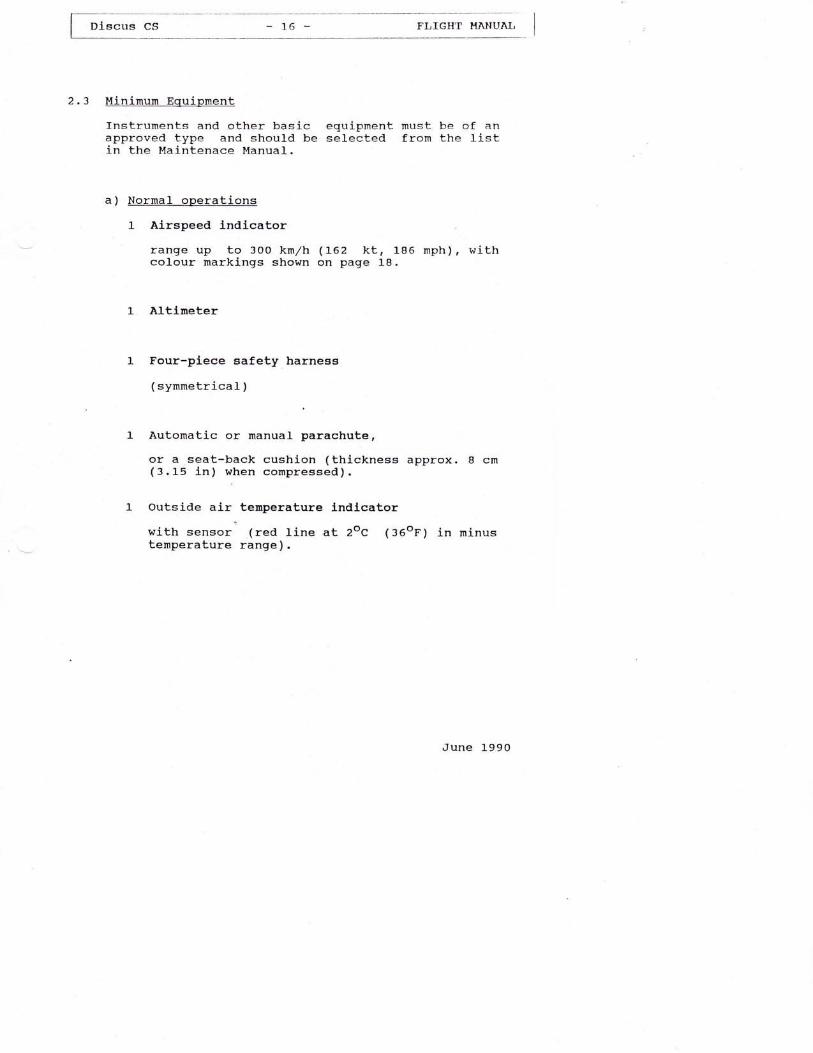
2.3 Hinimum Equipment
Instruments and other basic equipnent must be of anapproved type and should be selected from the Iistin the Maintenace Manual.
a) Normal operations
1 Airspeed lndlcator
range up to 30O kmrzh ( L62 kt, 1"86 mph ) , withcolour markings shown on page 18.
1- Altineter
1- Four-pl-ece safety harness
( synrnetrical )
l" Autornatic or nanual parachute,
or a seat-back cushion (thickness approx. I cm( 3 . 1"5 In ) when compressed ) .
1 outside air temperature LndLcator:
with sensor (red line at 2oc (36()r) in minustemperature range).
June 1-990

Discus
(Minimun Equipment,ctd. )
b) Cloud Flving
In addition toa):
the equipment listed in section
Turn & bank lndicator with slip ball
Variometer
vHF - Transcelver
Ilagnetic compaaE
Note:
From experience gained to date it appears thatthe A.S.f. system, as instaJJed, remains fu7lyoperational when flyinq in clouds.
Recommended additional equipnent for:
cloud flvinq
Artificlal horlzont
Clock
Restricted aerobatics
Accelerometer (3 hands, resettable)
For structuralinstrunent panel
reasons the weight of theand instruments must not exceed
10 ks (22 rbl.
June 1990

I Discus cs * 18 - FLIGHT HANUAL
(Minimurn Equipment,ctd. )
operating Instructions
^ FIight and Maintenance ManualI nata and Reference Placards
Airspeed Indicator Colgur Marklnqs
kn/h nph kt
Maximumpermltted speed Vt
"250 155 135
Maneuveringspeed VA 200 124 108
1.1 x stallingspeed 1-.1 x V=, 95 59 51
Green arc(normal range) 95. .200 59. .t24 s1. . 108
Yellow arc(caution range) 200. .250 124. .155 108. .1-35
Red radla1 line(never exceed) 250 155 135
Yellow arrow(approach speed) 115 7L 62
The stalling speed of which the alrspeed lndlcatormdrkings ire based refers to the followingconfiguration:
a) Airbrakes : Closed
b) Maximum weight ! Wrax = 525 kg (1157 Ib)
June 1990

Diecus CS -19- TLIGHT }IANUAL
2.4 Airspeed Limits (IAS)
knlh kt nph
Maxl-mum permittedspeed Vun 250 135 155
Maximum pernlttedspeed in rough air V* 200 108 t24
Maneuveringspeed VA 200 108 1"24
Maximum perrnlttedspeed on aerotow VT l-80 97 Lr2
Maximurn speedon winch iaunch* v,o 150 81 93
*Maxi*u* pernitted speed on autonobile & winchLaunch
Please note that with lncreaslng altitude trueairspeed (TAs) increases versus lndicated airspeed(rAs)
This is of no consequence with regard to thestressing of the sallplane. However, for flutterprevention the following speeds (IAS) must not beexceeded:
Altltude v( rAs )
m ft km/h kt mph
010002000300040005000
o3 28065609840
1312 016400
250250250250250243
135135t-35135t-35131
155155155l-55155151
Altltude v( rAs )
m ft kmrzh kt mph
6000700080009000
1-0000L2000
L95802296026240295203 280039360
2302L7205193L821,58
L24LL7111104
9B85
143135L27120113
98
June l-990

Discus CS -20- FT,IGHT I.TANUAI,
2.5 Load Factors
The following maneuvering load factors must not beexceeded:
at Va = zoo kn/h (1o8 kt, 124 mPh)
n : + 5.3
n:-2.55
at V*"= 250 km/h (135 kt, 155 mPh)
n = + 4.0
' n = - 1.5
Airbrakes closed.
Airbrakes extended : Maximum n = * 3.5.
2.6 welqhtE
kg tb
Ernpty weight(approx. ) 233 5r-4
Haxlmum permlttedall-up welght 525 1157
Maxl-nun welght ofnon-llfting parts 240 529
For maximum permltted water ballast refer to section2.7
June 1990

Discus cs -2L- FLIGHT }IAIUAL
2.7 Loadinq Table
Seat load (pilot and Parachute):
Minimum 70 kg ( l-54 . 3 Ib )
Maximum 11o kg (242.5 Ib)
te:As the actuai ninimum or naximun seat load
of this sailplane to trhich this nanual refersnay differ from the above typicaT veights, theseat Toad placard in the cockpit must show theactual weiqhts fron the log chart on page 26.
Pilotts weight of less than this minirnum seat loadrnust be raised by using trim ballast.
l-. Ballast (1ead or sand Lushion) must beheld in place by attaching it to thebrackets.
securely1ap belt
2. Ballast by means of lead plates can be installedinto the fuselage nose cone. 2.2 kg (4.85 lb)correspond to 5.0 kg (l-L.O lb) pilot weight. Theinstallation point ls 1715 nm (67.52 in) ahead ofdatun (BE).
Neither the max. perrnitted all-up weight nor themaximum weight of the non-lifting parts nay beexceeded.
Centre of qravity (C.G. ) of the pilot:(with parachute or back cushion)
45o mm (L7.72 in) ahead of datun (BE).
June 1990

Dl-Bcus cs -22- TLIGHT UANUAL
(Loading Table,ctd. )
Loadinq Table With Water Ballast
lltax permitted all-up weight(including water ballast) 525 kg (11-57 l-b)
Lever arm of water ballastaft of daturn (BE) 203 mn (7.99 in)
Table of water ballast at varlous ernpty weights andseat loads (pi1ot incl. parachute):
Baqqaqe Compartment
Max. permitted load ln baggage compartment!
2.0 k9 (4.4 lb)
This load must be considered when the maxinumperrnitted water ballast load is determLned.
Lever arm of baggage aft of datum (BE):
880 mm (34.65 in)
June 1990
EupLy
kg lb
Seat load PlloL and ParachuLe kg (ltr)
?o ( 154) aO ( 176) 90 ( 198) tOO ( 220) t 10 ( 243)
220 AA5 ta4 48.6 40.5 1A4 43.6 40.5 ta4 4e.6 40.5 184 48.5 40.5 184 48.6 40.s
225 496 ta4 44.6 40.5 7A4 4A.5 40.5 rb4 4B.E 40.5 la4 4e.6 40,5 ta4 4a.6 40.5
230 507 t84 48.6 40.5 la4 48.5 40.5 t84 48.6 40.5 la4 48.6 40.5 ta4 44.6 40.5
235 518 ta4 48.5 40.5 184 48.6 40.5 ta4 4a.6 40.5 1A4 48.6 40.5 tao 47.5 39.6
240 529 ta4 48.6 40.5 ta4 48.6 40,5 184 48.6 40.5 184 48.6 40.5 775 46.2 38.5
245 540 t84 48.6 40.5 !a4 48.6 40.5 7a4 4A.6 40.5 tao 47.5 39.6 770 44.9 37.4
250 551 ta4 4e.6 40.5 r84 48.6 40.5 184 48,.5 40.5 175 46.2 s8.5 165 43.5 35.3
I I Lers xxx) ...Inp.Gal1onsHater ballasL ln both vlng tanks
Dl-scus cs -22a- FLIGHT UANUAL
(Loading Table,ctd. )
Loadincr Table When Usinq The Fin Tank
In order to shift the center of gravity close to ltsaft linit (favourable in terms of performance),water ballast may be carried Ln a fln tank (mpr') tocompensate for the nose heavy monent of waterballast ln the wlng (mg1).
The deterrnlnation of the ballast quantity is donewith the aid of the dlagran on page 22 d.
June 1990

(Loading Table,ctd. )
Example
for the determination of the ballast quantity:
;-ExannIe-I
I rotal water ballast in both wing tanks
I mwT : 70 kg (liters)
I nesutting water ballast ln fln tank as shown inI
the dlagram on Page 22 d2
I rnFr = 2'o ks (liters)I
I a= tn" scale on the fin tank is graduated forI fuff kilograms (liters) only, a quantity of
| ,.o ks ( titers )
I
I is filled in fin tank.I
Lrnu of the example
June 1990

Discua cs -22c- FLIGHT UANUAI
(Loading Table,Using Fin Tank,ctd. )
When determining the quantity of water ballast forthe fin tank, bear in mind that the naximumpermitted payload (see 1og chartr page 26) roust notbe exceeded. Check as follows:
npILOT + .FT 3 (Iese or equal to the max. permittedpayload shown on page 26).
fn order to avoid that the maximurn permitted grosswelght is exceeded, the ballast ln the fin tank mustalso be consldered when deterrnining the naximumallowable water ballast for the wj.ng tanks.
Flying conditlons must conforn with the followingtable:
inltlng llnlts for fln tank:
Hinimumgroundtemperature
oc t-3.5 l7 24 31 38
oF 56 63 75 88 100
Maxinumabsoluteceiling
m 1500 2000 3000 4000 5000
ft 4900 6500 9800 13 100 16400
tLon:
Observe the outsideThe temperature
2
air temperature indicator.must not drop belowoc (:o on).
June 1990
The fin tank shouldls the danger of thefrozen.
never be used when therewater ballast becoming

Discus cs -22d- FLIGHT I.IANUAL
(Loading Table,Using Fin Tank,ctd. )
ma* Water ballast in fin tank:
Table for'the determination of fin tank ballastguantity. (See example on page 22 b)
(r)1"84
(us.s) (Im.g)8.6---r-40.
4 .9--137 .4
37.5-f-31.3
29.8-+-24.9
1
L4
11
2
8 22.s--+-'Lg .7
57 15. 1--l-12.
7 .4-1-6 .
.OlO.liters 0-1-2-3-4-5-5
June 1990
wing water ballast- m
ax
fIn
tank
baIIast
US.gaIIons o 0.26 o.53 o.79 L.06 1.32 1.58Irn.gallons 0 0.22 o.44 O.66 O.88 1.L0 1..32

2.a C.G. Positions
a ) In-f liqht -tl-_=-G._peEj!i-ql
Sailplane attitude : Tail jacked up such thata wedge-shaped block 100 . 4.4, placed on thefuselage tal1 boom, ls horlzontal along lts upperedge.
Datum (BE) Wing leading edge at root rib
ltax. f ort^rardC.G. position ... 260 mn (10.2a in)
aft of datum (BE)
Max. rearwardC. G. posltion . . . 4OO rnn ( 15 . 75 ln )
aft of datum (BE)
Make sure that the maximum permitted rearwardC.G. position is not exceeded - thls is ensuredwhen the minimurn seat load (pilot and parachute)is observed.A lower seat load nust be compensated by ballast.( See section 2.7 , rrloading tablert) .
b) Ernpty welqht C.G. posLtion
After repalr, repaJ.ntlng. lnstalLatlon ofadditl-ona1 equipment, rnodl-f Lcatlons etc. thecenter of gravlty must be re-determined byweighing the saitplanei in any case the Discus cSshould be re-welghted every four years. Make surethat the empty e.c. l-s withln the permlttedrange. If necessary, compensating ballast weightmust be install.edi
When the empty weight C.G. llmits and the loadingtable are observed, the c.G. positlon in fliqhtwill be within the pernitted range.
June 1990

Ftr""" "; -24- FLIGHT HANUAI,
(c.G. Positions, ctd. )
The deterrnination of the C.G.diagrams on page 25 A andfollowing seat loads:
ranges as shown in25 B is done with
thethe
ForwardC . G. Posl-tions : with a maximum seat
(242.5 lb) and withwater ballast
.load of 11O kgmax. permitted
RearwardC.G. Positions: With varlous rninlmum seat loads and
wlth 2.0 kg (4.4 lb) load in thebaggage compartnent
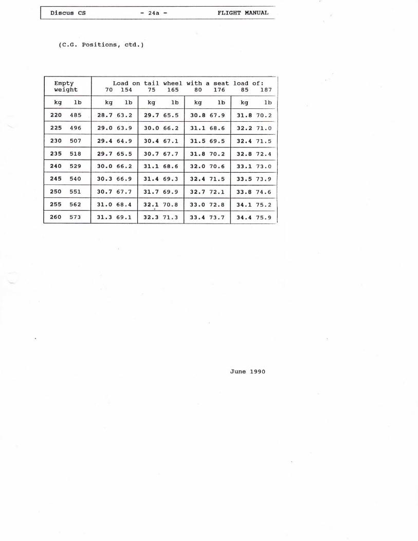
For easier deterrnination of the rremptyrt weightC.G.positlon the table on page 24 A shows, atvarious empty weights, the maximum perrnissible loadson the tail skid (or whgel - if installed) withvarious seat loads (with reference to the rearrnostc/G position).
Just determine the actual load on the tall skid (orwheel) with the sailplane being in weighing attitude(main wheel on the ground, tall jacked up as describedon page 23 ) .
If the determined load on the talL skid (or wheel - ifinstalled) is below the value shown on page 24 A, theC.G. positlon is withln the permltted range.
June 1990
Dlscus CS -24a- TLTGHT HANUAL
(c.c. Positions, ctd. )
Enptyweight
Load on tail wheel with a seat load of:70 1s4 75 165 80 L76 85 187
kg lb kg 1b kg 1b k9 Ib kg 1b
220 485 24.7 63.2 29.7 65.5 30.8 67.9 31.8 70.2
225 496 29-O 63.9 30.o 55.2 3l-. t- 68.6 32.2 7t -O
230 507 29 .4 64 .9 30.4 57. t" 31.5 69 . 5 32.4 7L.5
235 518 29.7 65.5 30.7 67 .7 31.8 70.2 32.8 72-4
240 529 30.o 66.2 31.1 68.6 32,O 70.6 33.1 73 . O
245 540 30.3 66.9 31.4 69.3 32.4 7L.5 33.5 73.9
250 551 30.7 67 .7 3L.7 69.9 32.7 72.1 33.8 74.5
255 562 31.O 68.4 32.1 70.A 33.O 72.8 34.L 75.2
260 573 31.3 59. t" 32.3 7t.3 33.4 73.7 34.4 75.9
June l-99o
Dlscus CS -25a- FI,IGHT I'TANUAL
(C.G. Positions, ctd.)
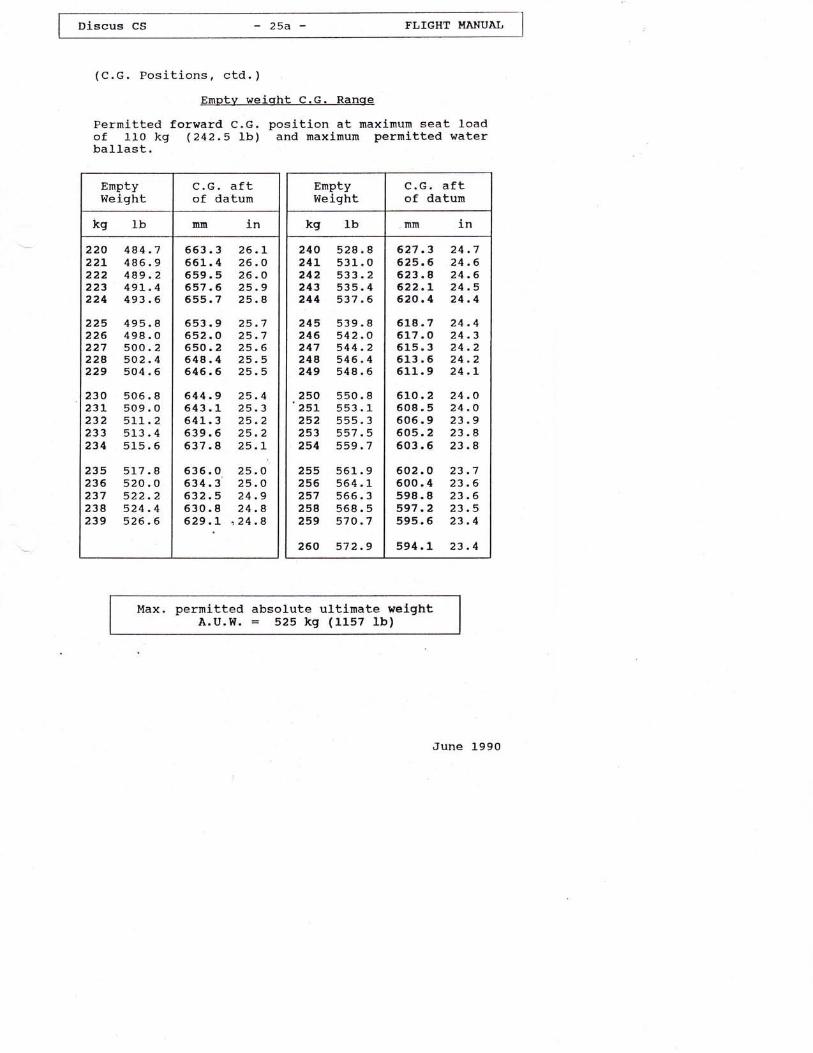
Emptv weight C.G. Ranqe
Permitted forward C.G. position at maximum seat loadof 110 kg (242.5 Ib) and rnaximurn permltted waterbaIlast.
Enptyweight
C.G. aftof datunr
Ibkg 1nlnrn
225 495226 498227 500224 502229 504
230 50623L 509232 511233 513234 515
235 5L7236 520237 522238 524239 526
220 4A4.722L 4A6.9222 489.2223 49L.4224 493.6
Io246
8o246
I0246
663.3661.4659. 5657.6655.7
553 .9652.0650 .2648.4546.6
644.9 25.4643.1 25.3641_.3 25.2639.6 25.2637.8 25.L
635.0 25.O634.3 25.O632.5 24 .9630.8 24.8629 .L n 24 .8
26.t26.O26.O25.925.4
25.725.725 .625.525.5
EmptyWeight
C.G. aftof datun
Ibkg 1nmm
240 52824L 53L242 533243 535244 53't
245 539.8246 542.O247 s44.224A 546.4249 s48.6
I0246
250 55025L 553252 555253 557254 559
255 56L256 s64257 566258 568259 570
260 572
I1357
913
57
627.3 24.7625.6 24.6623.4 24.6622.L 24 .5620.1 24.4
618.7 24 .4617 .O 24.3615.3 24.2613 .6 24 .2611.9 24.r
610. 2 24 .O608.5 24 .O605.9 23 .9605.2 23.8603.5 23 .8
602.O 23.7600.4 23.6598.8 23 .6597 .2 23.5595.6 23.4
594.1 23 .4
Max. permitted absolute ultimate welghtA.U.W. = 525 kq (1157 Ib)
June l-99o

ooo
oc)f)
.o
hI
x
.a
ul,x
q{o
.q'!r,doJJ0rrd i(om
;l .')
E
Eb
N00
o00
c
EE
V $:tCO(l0N CIFiOO OO000000 t\N\0\0lOt\ t\Nt\NN NNNNN \0\0\0\o\0 \0\0\0\0\0N NNC\NN NNNNN NNNNC! C\NNNNN O00\0Ort O00\Orl00 FO00l-O Io{ONr.N rO$ON-r O00N\0n SO!tOO 0ON\OUi{O OOOOO 0000000000 00000000N NC\Ni\N\o \0\0\0\0o \0\o\oo\0 \o\0o\0\0 \o\0\0\0\0
tro+,
UIo0.
()
U15t16I,rdoM
do
E1..
o0.
\0N
o00
EE
N NN\0\0 lf) nVr{m00 ONNr< iOOotot\0 \0\0\0\0\0 \0\0\0\0\0 \o\0\0\0\0 \0\0\0nnOI NNNC{N NNC\:S1 N C\]C!NNN OIOINNN00 iO00Nn $ON-,-, OOOO0\ OOOOOO 00Nn$01 NtOO(D N\OVON r.OO0000N NNNNN NNNOO \O\OO\O\O \O\ONNOo \0\0o\0o \0\o\0o\0 o\o\0\0o o\0oo\0
ln\0
nN
Ea
ts OOOOO 00()0t\Nt\ \0\OtOnn VrlVC000\0 \o\outlotll n!r!)nn nnn!Dn !Dnnn!3N NNNNN NNNNN NNNNN CINNNNo oooNN N\0\o\0\0 \0\0\0NN N00o\0\0N OO00N\0 tOSmN-. OO00NO UlS00NN\0 \ournnn u)nnnn !){{v{ tfsvs$\0 \0\0o\0\0 o\o\oo\o \o\0\0o\o ao\o\0o
$n
oN
c
Ea
O OONN- -.rOOO OOmm00 t\NN\0On nnnnut nlJDInnn VVVSV VV$V\tN C{NNNN NNNNN NNNNC! NC\NC\:C{
00 NNNNI\ NN0000O OOHN0/) $n\0NOO NTTOOO N\OnS00 flfirrOO 00N\0|l1$$ v$\to00 (400(l1(Y)01 01(Y)(r,,(r)N NNNNNo \0\0\0\oo o\0\0\oo \o\0\0\o\o \o\o\0\o\o
-)JEIP1'aEOId=
n
u!x
0o ONV\0c0 ON$\000 rrOlONO FO|.ONO0o -Ol0NCA NSO00O OONOr $\000OC\lN O(4f400cr) v$ssu3 tonnn\o \o\o\0Nt\lr) lrlluinnO n!0nnn nAnnn n!lUinno -,No$o \0N00o\0 nN01 vln \0N00o\()v {s!fv!f sv$vn !rnnnn nn!1naN NNNNN NNNNN NNNNN NNNNN
obcdfi\*)
dt{
(9
o
!,oU
boEX+)&ELI
diJu
o
o
+J
oo0"
(,U
0
.J
UI
oU
1,!d,,{dog!o.J
E1..
oA
n
.a
h)(
t{o
"a!a,do
11
,Utr{ )1otJ)
E.Q
E
cEbtx
uli(
N@
o00
c
EE
q 11tqI c'!::?? qqtq\ YYqq00 0000@0000 @m0000@ NNNNN NNNNN NNNNN CtNC{C\N NNNNN NC\lN.N
o r,0rNoo \0Nooni o0toNo\0 0tooototf NrrOCDt0 OrfN-tO 00NO$O N-,O00N NN-*=r tr?r!rFr?r OOOOO OOOON NNNNN NNt\NN NNt\t\N Nt.\O\0
\0t\
o00
aE
00 t\\0\0nn VSC0CON Ns=.OO OOC000
N NNT\NT\ NNNT\N T\NNNN \O\O\O\ON NNNNN NNC{O:N NNNNN NNNNO N00O\OC0 OO00ON $=.O\Orf rrONOn 6461 vrO00 \On$O-, OON\0tli {NFOo ooooo ooooo o00c000c 0000m00N NNN\0\0 \o\0\0\o\o oo\0\0\o \o\0ua
no
toN
Ae
t\.\0\01/)n n\titmm NNr-\0\0\0\0\o \o\0\0\0\0 \0\o\0\0NNNC!N NC{C{C\:C! NNC\NOOOrO ONAnrf ONrON\0nt(01 rOO00N \0Ui$0/)I\NNNN NN\0O\0 \OA\O\0o\0\o\0\o \0\0\0\0\0 ao\o\o
oNNorf00
oo0000N\0'o \0 \0 \0
"NNNNC,I\0$NooONrtO0000 00 00 00 t\\0\0\0\0\o
sfro
N
L
aE
N N*sOO OOo0000 NN\0\O\0 nnVVo o\0\0\0\0 nulnnn nnnnu) nnnuSN NO{C{C\N NNNNOI C{NC{NN NNNOIO ONIID$N rrO0oNn $ON:.O OO00O\0 $oNrro oN\0u1$ oNV.oor 00\0!ts\0 \o\0\oao nnnulul nnnns ${sv\0 \o\0\0\o\0 \0uoo\0 a\0\0\o\o o\ooo
-)x.c+)UtQ. 'xEOEl =
n
hX
N ON$\000 0Nv\000 0c!s\0@ oNs\0V r.0C^r(oO 00OC\V\0 o\;OION ONV\0@ @00O0\ot 0\OOOO Q*r*< NNNNs !tv{sv vrnnloto nnnnn nn!l)nO -rNOVn ON00OO rtN0')rftll) \ONC0ON NNNNN NNNN0l 04040101m O040400N NNNNN NNNNN NNNNN NNNN
J((
F.
orllq
I
"anC\
I
aU
UI
UUI
A

Jt4
dLFUHJfr.t
I
\oC\
UI
Utl
A
ooo
oc7h
ut&o
n0)ou
0)
oiJ
4lo
tdU
,d()U)
dc
x
aUrF.al
Lo.4E.
I
4'i-td."{Lq)
m
L
'r{
T,A-td
h&
U(,oJlllU
eJJoo
t-"
()HH>
{\ry J?D*?' 1"'-171.
2.-v?:ltLf H +4( nl )lolu,ilt '/
/".5t 4V+*--r;'
'/a"
$"1 $l
(-()o)o)
=
ut
!lJojJ rd
*)ino,6d
E- rlnrdA0,!AX
,{ rd.0erd rdJE3(
trt
E'dafJEO
rdd): 0.
J
JE1P" 'rEOId)
1JJOL+)(, r!E'd0.'a r)7Al/.rpl '<
ELE3
.JO v
ur, "^,A.A ltl(, (/) Al>O v
Aq{x oE0,o*)JE .q{ rd
Fl u (J'11
ultxCo.a
J.ddoA}
x
\{! q)
o crruJ
+) ,C,C, utno {u
'a- I0.- rd
E tI tl.

Dlecus CS -27- FLIGHT HAHUAIJ
.9 Towinq hook(s)
a) c.G. Release mechanism (if installed)For winch launching and aerotow the TOST releasemechani.sm
Safety release trEuroPa G 72tt orItEuropa G 73tt or ItEuroPa G 88rr
is used, which is lnstalled on the bottorn of thefuselage 1n front of the rnain landing wheel.
b) Nose tow release mechanism (lf installed)
For aerotow the TosT release mechanism Nose release
trE .72u or llE ?5n or trE 85rr iS uSed, WhlCh iS
lnstalled in the nose of the fuselage.
z.Lo weak links in winc@
For both winch launching and aerotow:
Maximum: 68q daN (L499 Ib)
The rnininun strength of the weak llnk should not beless than the value for the maxlmum a1l-up weight.
. LL Tire Pressure i.,3
up to 360 kg (794 rb) A.u.w. = 3.5 bar (so psi)Above 360 kg (7e4 lb) A.u.w. = 4.5 bar (64 psi)
2.12 Crosswind
Maximum crosswind component provenfor take-off and landing:
20 k^/b (s.5 m/s,Ll kt)
June 1990

.lr. App-Iy- fgll opposite rudder.,against thq
2. Ease the control stick forward unt'iI
. the rotation ceases.
:'' 3. Centralile.rudder, and pul1 out suoothly
f rorn dive.
June 199q

.r'. :3r.,2 Emeigenclz"Exit.: -
' ' l:
"'
,In'cas'e of da-nger., the .r.oony, and:unclutter:ed 'Gockpit ,
engu!,esra. qUick arid safe:energency,exiti : : '., l
,The :procedure for',jbttisoning the qan-op)f is' asfollows:
1, L..,'Sryi.ng carl.opy 1oc\i4g1' Ieve5 (with ::e$,kqrob) ,
,' , . 'on 'the, '1eft: side'. , ofi,, . the.,. canop11,,framer"' .
:2. Push red :knob,ll.ocated. dlreqf'lt belott:. the-r,'', !!qtr!- hand.canopy' frarne' fqrt'rarq.
r3n 'Tlrrow off. thq canopll; .
' '.' ': ' made',''of f iberglass larniriates, . strong rqnd' ,l.,.: .i ,r - withsut sharp .edges, so the pilot,nay'qse':rit 't-
for support when bailing out.]:
r, .:' :: :'. ; T.he forward'hinged instrument,, panetr..,giges .,:' : ' ,.. , under liElit: preqsurie by: hand:'or'with t.he. Iegis;, ,.;,. : . , .'.: "':,thus allowinf .for anr,easier,'etnergenc!:lsxig': ;. ,,'.: .
June. t99o
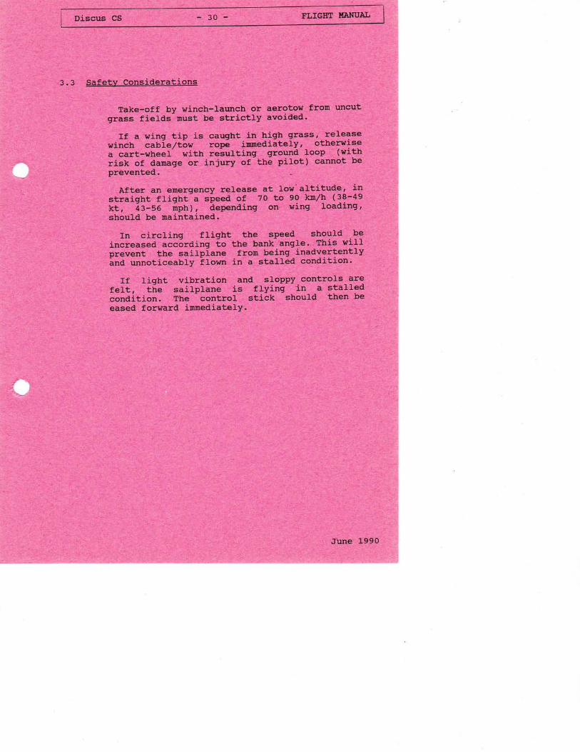
3.3 Safetv Considerations
Take-off by winch-taunch or aerotow from uncut". , ,, ':;grass ti'-efai"mGt'be.'strictly'avoi-dedr ,,
', 1 , -r, i. ' trf..a,ving'tjp,ria,caught ihr hign'graqs{':I_e1:1?:!',t' I i. , wlndtr eiureTtotl, j,'tibPg
, iunbdiately,'- ottteryis€:' I ii ''.'ar:cart-wheel: wtth' relurtinq:., ground' -}gop :t, lwittl1,, ,' ."', i 'risk. of damagg or injuqlz'91 ,thq pilot) cetl1o! be
prevented.
After an emergensy release at low'altitude, in:: " , ' ,'slriight-r:fliglt-a,speeil of ' 7a' to 90, kx0lh'.(38'r'49... ' "'. ', kt,. ii-sa" 'iiptr)I.'iglienOing onl iwing. rloading,,: :',, , ,1 ..,;slro d b6 ,rnaint4rqeg:: ,,.. ,: ,: 1-i, .,. r
In circling flight tlre speed should .be',' ', , , -::I inlJ;es edl aca;rding,io,t'rre,, bank--ang|.e. ,This r'ri1I',, :, revent :-iie' Uiipl-iir' lrfron being -inaa19rfently
,',,: ,', '','ipd,unnoLiqeabfy. !lor'rr' in,i, alr'ed cqndltion.t :
; ' .. ,, l,j3 ': liqtrt:' -vii="tton,'r'and sloppy controrsrSiS
: . . :'." fe t, 'tfre: sa5.-Ip1ane, ,,,1s,. fLying,': .in q.,'sgalf3d' ' t,.' c6naiiion. The'.''cqntrol', stick,l should ' then be
eased forward irnmediatelY.
Jllne Ivvu

Ft,lG}IT }IANUAI
4. Normal operations
4.1. Dailv Inspection
Before commencing the dayrs flying or after riggingthe sailplane it is very important to inspect itcarefully, ds accidents often occur when thesedaily inspections are neglected or carried orrtcarelessly.
When walking around the sailplane, check allsurfaces for paint cracks, dents and unevenness. Incase of doubt, ask an expert for his advice.
Open the canopy and check forward hingedinstrument panel for proper function.
Check that ^ the main pin is fully home andsecured.
Make a visual check of all control circuitsin the cockpit.
Check controls for fu1l, correct andrnovernents.
Check for foreign objects.
June 1990
.-l
a)
b)
c)
d)
e)
free

DIEcus cS -32- FLIGHT HANUAL
(Daily Inspection, continued)
f) check main wheel tire pressure:
up to 360 kg (794 Ib) AUW: 50 psi (3.5 bar)up to 360 kg (794 lb) AUw: 64 psi (4.5 bar)
S) Check condition and operation of the towhook( s ) .
2. a) Check upper and lower wing surfaces fordamage.
b) clean and grease water dump valves.
c) Check ailerons for proper condition and freemovement.
check for unusuat play by gently shaking thetraiting edge of the aileron.
Check hinges for damage.
3. Check airbrakes for proper condition, fit, andlocking.
4. a) Check fuselage for damage, particularly theunderside
June 1990
I niscus cs - 33 - FLIGHT HAHUAI
(DaiIy Inspection, continued)
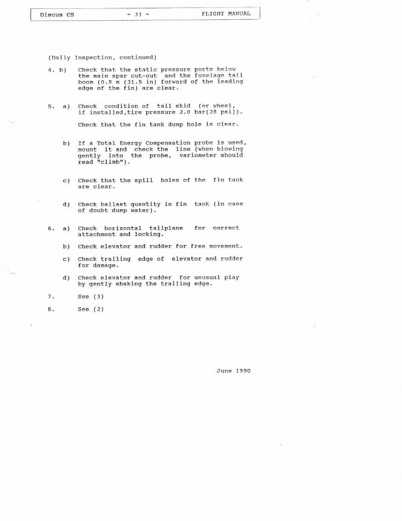
4. b) Check that the static pressure ports belowthe main spar cut-out and the fuselage tailboorn (0.8 m (31.5 in) forward of the leadingedge of the fin) are clear.
Check condition of tail skid (or whee1,if installed,tire pressure 2.0 bar(28 psi) ).
Check that the fin tank dump hole j-s c1ear.
If a Total Energy Compensation probe is used,mount it and check the line (when blowinggently into the probe, variometer shouldread rrclimbrr ) .
a)5.
b)
c)
d)
a)6.
Check that the spillare clear.
holes of the fin tank
( in case
b)
c)
Check ballast quantity in fin tankof doubt dump water).
Check horizontal tailp)-ane for correctattachment and locking.
Check elevator and rudder for free movement.
Check tralling edge of elevator and rudderf or darnage.
Check elevator and rudder for unusual playby gently shaking the trailing edge.
See (3)
See (2)
June 1990
d)
7.
8.
(Dai1y Inspection, continued)
9.
10.
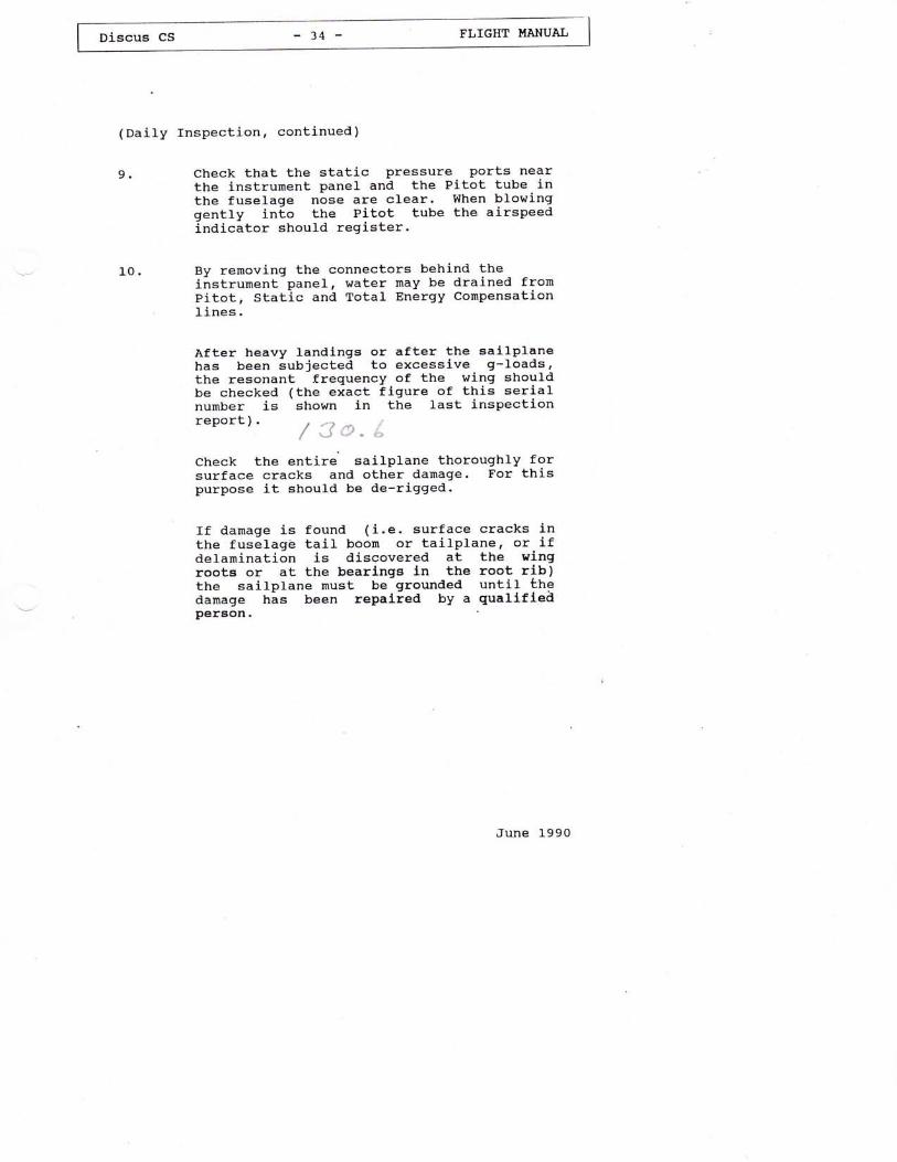
Check that the static pressure ports nearthe instrument panel and the Pitot tube inthe fuselage nose are clear. When blowinggently into the Pitot tube the airspeedindicator should register.
By removing the connectors behind theinstrument panel, water may be drained fromPitot, Static and Total Energy CompensationLines.
After heavy landlngs or after the sallplanehas been subiected to excessive g-Ioads,the resonant frequency of the wlng shouldbe checked (the exact figure of this serialnumber is shown in the last inspectionreport). t /.) */ J::r" '-Check the entire sailplane thoroughly forsurface cracks and other damage. For thispurpose it should be de-rigged.
If damage is found (i.e. surface cracks inthe fuselage tail boom or tailplane, or-ifdelamination is discovered at the wingrootg or at the bearlngs ln the root rib)the sailplane must be grounded until Lhedamage h-as been repalied by a quallfieiperson
June 1990

4.2
4.3
Discus cs - 35 - FI,IGHT II{ANUAL
Pre-fliqht Inspection
Refer to cockpit placards.(See chapter 1.2, page 5)
Take-off
4. 3 .1 Aerotov/
Maximum pernitted speed on aerotow
Vf : 180 kn/h (97 kt, l-12 nph)
Use the C.c. hook for aerotow, or, if installed,the nose tow hook. The Discus has been aerotowedusing hernp and nylon ropes of between 30 and 60n (100 and 200 ft) Iength.
For take-off set trim to about one third travelfrom its forward position (with the C.G. in aftmostposit,ion the trim should be fully noseheavy).
As the tow rope tightens apply the wheel brakegently so that the sailplane does not overrun thetow rope.
For intermediate to forward C.c. positions theelevator should be neutral for the ground run; inthe case of rear C.c. positions it is recommendedduring the ground run that down elevator is applieduntil the tail lifts.
Due to the control circuit geometry of the aileroncontrol slightly larger control stick movements arerequired during the take-off run.
After lift-off, at about 75 to 95 km/h (40 - 51 kt,47 - 59 nph) - depending on the load - the trin canbe re-set for rninimum elevator control Ioads.
June l-990

Dlscus cs - 36 - FLIGHT I'T,ANUAL
(Aerotow, continued)
Norma1 towing speed is in the region of l-00 to120 kmrzh (54 - 65 kt,62 - 75 mph) and between 12oand 140 km/h ( 65 - 76 kt, 75 - 87 mph) when waterballast is carried.
To keep station behind the tug only small controlmovements are necessary.
correspondingly greater control movements arerequlred when flylng the sal-lplane into the tugrspropeller slip streami furtherrnore, tailplanevibratlon occurs and the airspeed lndicator readingvaries.
The undercarrlage nay be retracted during tow;this is not, however, reconmended at low altitude,as changing hands on the control stick could easilycause the sailplane to lose station behind the tug.
When releasing the tow rope, pull the yellow gripfully several times and turn only when definitelyclear of rope
With stronq crossrrind and rear C.c. position applydown elevator during the ground run. For other C.G.positions the elevator during the ground run shouldbe neutral.
For rear C.G. posltion trlm heavy nose. For otherpositions the elevator trirn is in the one third ofthe range from the forward position.
June 1990

[;;-;; -37- FI.,IGIIT I,IAIIUAL
4 .3 .2 Winch launc,bing
Maximum permitted
Vw = 150 km/h
winch launch speed
(81 kt, 93 mph)
Winch launchlng I-e pernlttedonly when the C.G. hook l-a ueed.
The trlrn is nornally set at a mid-point position,for rearward c.c. posltlons lt should be set tofully nose heavy.
As the cable tightens, apply the wheel brake gentlyin order to prevent the sailplane overrunlng thewinch cable.
Ground run and lift off are normal and there is notendency to veer-off or to climb excessively steeplyon leaving the ground.
Depending on the seat load the sailplane is liftedoff with the control stick alrnost fully pushedforward in the case of aft C.G. posJ-tions andslightly pull-ed back with the c.G. in a forwardposition.
After climbing to a safe height the transitlon to atypical steep winch launch ctimbing attitude j-seffected by easing the control column back slightly.
At normal flying weights, without water ba1last,the launch speed should not be less than 90 kn/h(4g kt, 56 mph) i and with water ballast not lessthan L00 to 110 km/h (54-59 kt, 62-68 mph).Normal launch speed ls about 1oo km/h (54 kt, 62mph), with water ballast about 115 to 125 kn/h(62-68 ktt 7l-77 mph).
At the top of the launch the cable will norrnallyback release automatically; the cable releaseshould, however, be pu1led flrmly several times toensure that the cable has actually gone.
June 1990

Discus CS - 38 - FLIGHT I.IA}TUAL
(Winch launching, continued)
June L990
-fmportdntWinch launching at . maximum perlnitted all-upweight of 525 kq (1157 lb) should only beperiormed if an appropriately strong winch and acabte in perfect condition are available.
There is not much point in using a winch launchfor a soaring fltght if the release helghtgained is less than 4oo n (1"300 ft).
The length of the cable should also correspondto this condition.
In case of doubt, reduce al1-up weight to e.g.4OO kg (882 1b) or less.
Winch launching with waLer ballast ls notrecommended if the head wind is less than 20kn/h ( 5 .6 m/s, 1-1 kt ) .
It is explicitly advised'against winch launchingwith a tail wind.

I olscus cs - 39 - FLIGHT HANUAL I
4.4 Free flight
This sailpane has pleasant flight characteristicsand can be ilown effortlessly at all speeds, loadingconditions ( with or without water ballast),configurations and C.G. positions.
with a rnid-point c.G. position the speed rangecovered by the trim is from about 70 kn/h to about22o km/h (38 to 1L9 kt, 43 to 137 mph).
Flying characterlstics are pleasant and thecontrols are well harrnonized.
Turn reversal from 45o to 45o is effected withoutany noticeable skidding.
Ailerons and ruder nray be used to the limit oftheir travel.
Tines required are shown below, figures set inparenthesis refer to 525 kq (1157 lb) A.U.l'l .:
ines of revereal t
June l-99O
----{ines of reversal turns-km/h kt nph seconds
95 51 59 4
L20 65 75 3

Dlscus cS -40- FLIGHT I.TANUAI,
4.5 Lor"r Speed Handlinq and Stall
In order to become faniliar with the Discus wereconmend exploring the low speed and stallcharacteristics at a safe height.
Stalls should be approached from stralght flightand from turning fllght (with approx. 45" bank).
Stallinq from straight and level fliqht
The following stalling speeds are typical instraight flight:
A.U.W 333 kg 734 lb s2s kg 1157 Ib
c.G.aft of
datun (BE)
mm tn mm .l-n
400 15.7s 260 LO.24
Airbrakes kmrzh kt mPh kn/h kt nph
Closed(nose hook)
58 31 36(<60) (<32) (<37)
83 45 52(77 I (421 ( 48 )
Extended(nose hook)
63 34 39(<60) (<32) (<371
88 48 55(77 I (42) ( 48 )
Figures shown ln parenthesis apply for sailplaneshaving a nose.tow hook installed which causesa large airspeed indlcator error around the statlingspeed.
In the nose of the C.G. being at the fully aftposition stall warning occurs 3 to 5 kmrzh (2-3 kt,2.3-3.5 mph) above stalJ.ing speed and is indicatedby vibration in the control system. When pulling thecontrol stick further back, vibration increases upto the point of stall and the ailerons get spongy.
With the c.c. at the fully forward position stallwarning occurs just before the stalling speed isreached. The elevator and rudder control of thesailplane is normal up to the point to stall.
June 1990

I Dlscus cs - 41 - FLIGHT HANUAL
(Sta11ing from straj-ght and level flight,ctd. )
When reaching a stalled condition vrith the C.G. atan aft position the sailplane may drop a wing butusualy the wings can be held level.
When the C.c. is forward, the sailplane wiIlsimply stal1 straight ahead with ful1 aft stick.
Transition into a norrnal flight condition isperforned by releasing the back pressure on thecontrol stick and, if necessary, applying oppositerudder and aileron.
Turning fliqht stalls
When approachJ-ng a stall from a coordinated 45obanked turn with the control stick fully pulled backthe sailplane either continues to fly in a stalledconditlon or it drops a wing abruptly.
With the C.c. at forward posltion and the controlstick fully pu1-Ied back it simply sta1ls.
Transition into a normal flight condition isperforrned by approprj-ate. ube of controls.
Spins
In the case of aft C.c. position, application offulL ruder when the sal-lplane ls stalled willproduce a spin.
June 1990

Dl.scus CS -42- FLIGHT HANUAL
(splns,ctd. )
Wlth the C.G. atr aftmost positlon osclllatlons lnpltch occur durlng a spln.
If alleron ls applled In the dlrectlon of the splnthe pltch attldude steepens and the rate of rotatlonLncreases.
Followlng the standard recovery procedure the lossof hstqhE durlng r€covory from a rpln Isapproxlmately 50 to 80 m (164 Lo 262 ft) meaeuredfron the polnt at whlch recovery ls lnltlated to thepolnt at whlch horlzontal f1lght ls regalned.
Unfavourablc (atecp) attltudar on rGcovcry rlght . Icvon ceuae a 1o"r oi helght of up to lJo r (\fz rt;';
Recovery speed le between about 12O and 190 km,/h(65 and 103 kt, 75 and 118 mph).
A eafe recovory from the spln Ie effected byfollowlng the standart procedure:
a) apply opposlte rudder, I.e. agalnst dlrectlonof epln
b) shorts Pause
c) oase the control column forward untll rotatlonceases and the alrflow is restored
d) centrallze "rudder and pull gent'Iy out of theresultlng dlve.
Wlth the C.G. at the fully forward poaltlon Eplngcannot be lnduced, but, dependlng on the -use ofcontrols a splral- dlve may develop. The eallplanewlll gulckly recover fron thls condltlon by nornaluse of oPPoslte controls.
TECHNICAL NOTE NO. )60 - 1) June 199't

Discus CS - 43 - FLIGHT HANUAL
4.6 High Speed Fliqht
when flying at high speeds up to VuR = 250 km (135kt, l-55 mph) the sallplane ls well cijfrtrolable.
FulI deflection of control surfaces may only beused up to vA:200 km/h (1o8 kt' 124 mph).
At Vxn = 25o km/h (135 kt, 155 mph) only L/3controll^ed deflections are permitted. Avoidespecially sudden elevator control movements.
In strong turbulence, i.e. in wave rotors,thunderstorms, visible whirl winds or when crossingmountain ridges, the speed in rough air V*o = 2ookm/h (108 kt, L24 nph) nust not be exceeded.
with the C.G. in rearwand positions the controlcolumn movement from the point of stall to max.permissible speed is relatively small, though thechange in speed wl1l be noticed througha perceptible change in control colunn loads.
The airbrakes may be extended up to Vue = 2sokmrzh (135 kt, 155 mph), however, they should only beused at such high speeds in emergency or when themaximum permitted alrspeeds are being exceededinadvertendly.
As the airbrakes are very effective thedeceleration forces are considerable lf they areextended suddenly.
Therefore it must be ensured that the harness istight and that the control column is notinadvertently rnoved when the airbrakes are extended.
Avoid loose object 1n cockpit.
June 1990
O O - FLIGIItT IiANUAL I
(Hiqh Speed rliqht, ctd. )
It should also be noted that with the airbrakesextended the sailplane should be pulled out lessabruptly than with retracted alrbrakes (see section2.5, load factors ) .
A dive with the airbrakes fully extended- isllnited to an angle to the horizon of about 30o at,i"ir". permitted all-up weight and to about 45owithout witer ballast at speeds of approxlrnateJ-y 25okm/h (l-35 kt, 155 mph).
June 1990
4.7
Discus CS - 45 - FLTGHT HANUAL
Flvinq with water ballast
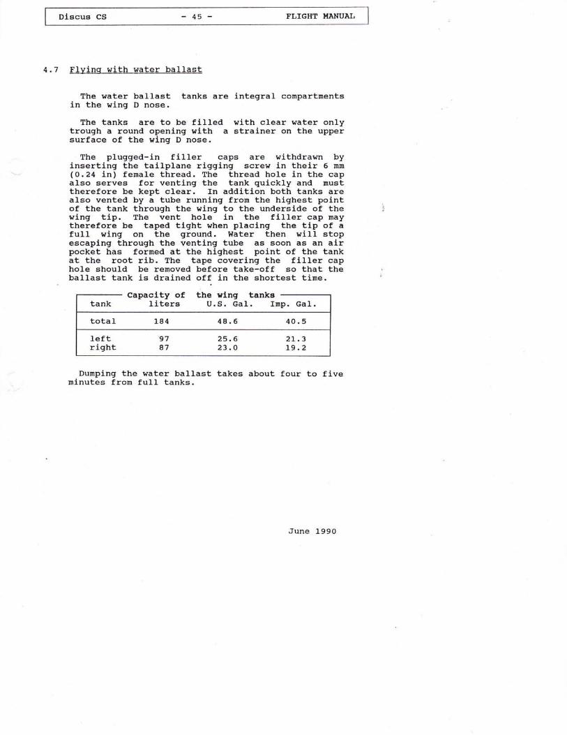
The water ballast tanks are integral conpartmentsin the wing D nose.
The tanks are to be fllled with clear water onlytrough a round openlng wlth a stralner on the uppersurface of the wing D nose.
The plugged-in fil1er caps are withdrawn byinserting the tailplane rigging screw in their 6 mm(o.24 Ln) fernale thread. The thread hole in the capalso serves for ventlng the tank quickly and rnusttherefore be kept c1ear. fn addition both tanks arealso vented by a tube running fron the highest pointof the tank through the wing to the underslde of thewing tip. The vent hole in the flller cap maytherefore be taped tlght when placing the tip of afu1l wlng on the ground. Water then will stopescaping through the venting tube as soon as an airpocket has formed at the highest point of the tankat the root rib. The tape covering the fi1ler caphole should be removed before take-off so that theballast tank is drained off in the shortest time.
Dumping the water ballast takes about four to fj.veninutes from fuI1 tanks.
June 1990
Capaclty of11ters U.S. Gal. Inp. Ga1.
total 1"84 48.5 4O.5
left 97 25.6 2L.3right a7 23.o L9.2

t- - --------- I
I Dtscus cs - 46 - FLTGHT HANUAI I
(flying with water ballast,ctd. )
When filling the tanks bear in nind the weight ofthe pilot and ensure that the maximum permittedweight is not exceeded (see loading tab1e, section2.7, page 22).
Both tanks should be filled with about the sameamount of water to prevent lateral imbalance. (withful1 wing tanks their different capacity ls hardlyperceptible as the excess weight is situated nearthe root rib).
When taking off with partly fu1l ballast tanksensure that the wj-ngs are held 1evel in order toallow the water to be equally dlstrlbuted so bothwings are ballanced.
Because of the additional weight in the wings thewingtip runner should continue running as long aspossible during the launch.
Thanks to the integral bulkheads in the ballasttanks there is no perceptible rnovement of the waterball-ast when flying wj-th partially full tanks.
When f lying at rnaximum perrnitted A.U.W. the lowspeed and sta11 behaviour of the sailplane isslightly differerit frorn the flight characteristicswithout water ba1last. The stalling speed increases(see sectl-on 4.5), and for corrections of the flytngattitude larger movements of the control surfacesare required. AIso, for recovery from a stallslightly rnore height is necessary to regain normal-flying attitude.
June 1990
Discus cS -47- FI,IGHT I{ANUAL
(Flying with water ballast,ctd. )
Water ballast is dumped through an opening on theIower wing surface near the root rlb.
The dump valve mechanism is hooked-upautomatically when the wings are rigged.
In the unlikely event of the tanks emptyingunevenly or only one of then emptying (recognized byhaving to apply up to 5ot opposite aileron fornormal flying attitude), it ls necessary to flysomewhat faster to take into account ther increasedweight and also to avoid stalling the sailplane.
If, despite this, the sailplane should enter aspin with a very flat angle to the horizon, then,for spin recovery according to the standardprocedure, full forward stlck is required and theairbrakes must be extended.
When landlng, be prepared to veer of courser dsthe heavier wing will touch down somewhat earlier.
Fin Tank
The forward travel of the center of gravity,caused by water ballast in the wings, maY becompensated by carrying water ballast in a fin tank,thus regaining pptimun performance in circlingflight
For i-nstructions how to use the fin tank refer tothe foltowing pages: 22a,22b,22c, 47a, 47b.
June 1990

oU\
o
)r')
;;?;?T;
+JooHk.0J 0,O.!al
troo.q .'{+J ,-{.-t.C i+{Ut5(,O.qH.IJ.|J
oEn.dao
'r4.lJt!r,+JC
(U
.H C'q{ .i0, .q
rJ^
c{ +JOFI
Utct'.r X!trtno.>\o
0,..1 tdd'lror+{0, .U!crOO qrq.{tr lJ.Cr. f'l0,(?|O.C +J)1H.cd 9ro'-l E+J . +{ .+). +J O |d+J (d UlFl OOkOOT r6to $ +JlJr{ '.{C vovO.( -t. -Ctr .Cq, 0).rt .6 o +J +J r-.t \o d.Fi (d 6 ur.lJ B\ tr AE ''r td O | '.{rd.rro aE*.,1 EC> A>,!(C}1 .CO3 (,c! E o .lrl{lo +rB EO O 0, Oo ^.a d O o. '-t O +rRp trco..{r-{ko .oElE }o.q.+r.-l O OFi . k d O.-l .d9^ trk.-r ldlll5.Ald +r9{> t,.lJ c{ dorJ) tr0ror.,tJro> -oHoc, utro .lrE 'ri9 0r!OO Odk OOTHOO\o +J(rt{E OE bi Q-rU r-{ EnOv O E O d O O O )1 E O O O 0, rd Ul0r6.C...{-COtr AAc o l,.lJO. Ul
C.-llrlr+r d E &'-l O 0, tr rd 0,F{ U! C d O l.{ ,4.-l q.{ r-{ .Q O O - -ird,r4 O .lq{OO OX.{ O P.Cl-'lr o lr o d o.-t (! (6r-rq{.c o o c, . o^b.'lo O! tr O O E d O lrd PrN .r kO . >rJ-.r H g. O E OIJlr\o 9a O(dOd't{ \ qJ o Ol.{ lF1tr o.+.lb.a-t OO)4oo o -oo..r . -tl tr a tu q{.C trd O -rE lr Oq{^ d 0,.-r 0,9 ' {J 6..r.C O O 0. tr Enco. 0, tr-.c c o .lJUlH .c.{o(d ox(, .-{ .{ O.rl +J .Fl g -t I A>(d r-.t.Q (d t{ o l{ +r . F{..{ o 6 c+rU --,l'a]J 0rE0r0, OO.C^ '{q-{6 O'-{o --r . q{.p c.Q o F{ tr .'r"{.c ur.c .-r o o ul..{ (J O O, k.i 16 O +r'.1 O Oro t,i O Odtd.E O O (,) +J r+{..1 Fl O l.| .lJ Ul -'{ -r{ O -l O
,51 O.l-.{ .rt.'l q.{ Q F{ .C q-{ 0) 5 - O ktr(d +Jl.{t{b! a olJoox rHxIt a,0o.n )(uo0,q ."r .cq Eo, otroo do+) r+ C {d.lJ'i.-t 0, d O O+J O t6 !}1 O 6. 6F{.Orrd.C+J > O Ui l.l+J C O{Okrur-r ppi}--r ,H r-ro.p br5 o +rrd dEO q{! .{ .lo trtrr! .QOt.l.t lJ{J.C - q (d .p.d .Fi qO.-lt'l EE6td.lJ. ..lO OOC+r gr O >l ,.P.rb OE3.-l-{ q{.{ O.C !..r C O t6 d C k tr -i q >q)
! ri .Q+r+r q'+.l O ^0, d O O (0..1 6l.{o u o.-r N x .+r pr+r o g-q 3 3..{E . tx^o^ ..r ..roHdE16 Eo daHCc0 HO^+.1 ^Ot{ (/)rlr(.)O} tsr|iO(, <tt.rr. -{ccc!o .rFlo() ol.q 0,q{ 5 q{..{.r{ -d +J -C o.-d d rd .a .lJ p !
uoq,..r l{.6d+J
.alrot{.+J.i o q,
Fl o+J_tv.q (d0!.cUlo)1 ! a)6+J>!..{ ..{("l L u-e
0, u 1.,Ir{ } 0)oooc,,-{ x .c
+J O,' +J
uro, E.-i,c > Uta]JQaF (!0+J Fr .+Jo cE{600)(,,Ft OC,.{ -o otddFl tU,a0rooko
'-i 6 0)dr0,vqqr0,(6H l{.IJ
a;-1aEr!xfrl
J4
'4
FoHJEr
I
rd
NvI
aU
r/l
oU]
A

----lI niscus cs - 47b - FLTGHT HANUAL
I
(Water ballast 1n the fin tank, ctd. )
water ballast is dumped from the fin tank throughan opening on the underside of the fuselage oppositeto the rudder
The fin tank dump valve is llnked to the dumpingmechanism of the wing tanks such that all threetanks always open simultanously.
Dumping water ballast from a full fin tank takesabout 2 to 2.5 mlnutes, i.e. half of time requiredfor the wing tanks.
Dumplng water ballast frorn the fin tank thereforeJ-s always qulcker than from the wlng tanks.
June 1990

Dlscue CS -48- FLIGHT HANUAI,
(F1ying with water ballast, ctd. )
Important
1.
2.
on longer fllghts at temperatures near ooc (32oF)water ballast must be dumped in any case whenreaching a temperature of 2oc (36oF).
There is little point ln uslng much water ballastlf the average rate of ctlmb expected does notexceed 1.5 m/s (295 ftrzmin). The same applies tofllghts in narrow thermals requlring high anglesof bank.
Before an off-fleld landing \.rater ballast shouldalways be durnped.
on no account whatsoever must the sailplane everbe parked with full balLast tanks, because of thedanger of them freezing up. Before the sailplaneis parked draln off all water conpletely, removethe filler caps and allow the tanks to dry out.
Before the water tanks are filled, check with thedurnp valves opened that both drain plugs open,move and close simultangously. Leaking (dripping)dump valves are avoided' by cleaning and greasinqthe valve seats and draln plugs (wlth the valvesopen), then, wlth the valves closed, the dralnplugs are pulled ln posltlon wlth tne threadedtool used to attach the tallPlane.
3.
4.
5.
6. Never pressurize the tanks, for instance byfilling directly from the water hose; watershould always be poured in.
7. Before the fin tank is filled, check that thosespill holes not belng taped closed are clear.
June l-990

^lru; i
4.8 Cloud Flvinq
This sailplane is sufficiently robust and stablefor cloud flying. It is simple to control and isstable in a turn.
Certain basic rules rnust be observed however.
Under no circumstances may the speed timitationsbe exceeded.
It is recommended that the airbrakes be extendedfully if the speed builds up to 13o km/h (70 kt,81 mph) or if more than 29 are pulled.
rhe addltlonal equipment requlred for cloud flyingis to be observed. (See chapter 2.3 b, page 1"7).
4.9 Flvinc, at temperatures below freezinq point
when flying in ternperatures below ooc (32oF), (asin long wave or during the wlnter months) it ispossible that the usual ease and smoothness of thecontrol circuits ls reduced.
Ensure that al-1 control elements are free frommoisture so that there ls no danger of then freezingso1id. This app"lies especlally to the al-rbrakes.
It has been found beneflclal to cover the matingsurfaces of the alrbrakes with Vasellne along theirful1 length so that they cannot freeze solid. Movethe control surfaces occasionally.
When flying with waterinstructions in section 4.7.
ballast note the
June 1990
ution:Only pernttted wlthout water ballast.

Discua cS -50- FLIGHT I,{ANUAL
(flying at temperatures below freezing point,ctd. )
warninq
The polyester coating on this sailplane is knownfrom many years experience to become very brittle atIow temperatures.
Particularly when flying in long wave at. altidudesabove about 6000 m (approx. -20000 ft), wheretemperatures of below -3ooc (-22oF) may occur, thegel coat, depending on lts thickness and thestressing of the aircraftrs components, is prone tocracking.
Initially, cracks will only appear ln thepolyester coatlng, however, with tirne and changingenvironment, cracks can reach the epoxy/glassmatrlx. Cracking is obvlously enhanced by steepdescents from hlgh altitudes at associated very lowtemperatures.
Therefore, for the preservation of a propersurface finish free from gracklng, the manufacturerstrongly advises agalnst. hlgh altitude ftights withassociaLed temperatures of clearly below -2ooc(-40F).
A steep descent wlth the alrbrakes extended shouldonly be conducted 1n case of emergency.
June 1990

FLIGHT HANUAI I| --*--- -- |
4.1o Restricted Aerobatics
utlon:
onl-y pernltted without water ballast.
The Discus cs is permittedfoJ-lowing aerobatics maneuvers:
a) Inside Loopsb) spins
Inside Loop
Enter the maneuver at a speed]-L2 mph) IAS. Speed duringmaneuver: Approx. 17O km/h (92 kt
Spins
to carry out the
c) Stalled Turnd) Lazy Eiqht
of l-8O kmrzh (97 kt,recovery from the, 1O5 mph).
Splns are only possible when the C.G. posltlon lsaft. Enter the spln fron a stall by applying fullrudder and with ailerons neutral. HoId the stickhard back while spinning. Recover from the spln byapplying opposite rudder. and easing the stickforward with the ailerons neutral. Recovery speed isabout 14O krn/h (76 kt, 87 nph). If spun with theC.c. at the fully aft posltion, the spin willcontinue for approximately half a turn afterrecovery action is initiated.
Stalled Turn
Enter the naneuver at speed of 160 km/h (86 kt,99 mph). while 'climbing vertically let the wingwhich will be on the lnside of the turn drag andthen at about 1-4o km/h (76 kt, 87 mph) apply rudder1n the directlon of the dragging wLng ln order toprevent a distorted maneuver. Speed during recoveryfron the maneuver: Approx. l-50 kn/h (81 kt, 93 mph).
Lazy Eiqht
Enter the maneuver at a speed of L60^km/h (86 kt,gg mph). After pulling up in a 45u clinb entera turn at about L2o km/h (65 kt, 75 mph). Recoveryspeed: Approx. 15O km/h (81 kt, 93 nph).
June 1990

4.11 Approach and Landinq
Normal approach speed with airbrakes fulIyextended anil- with the undercarriage lowered is 95km/h (51, kt 59 rnph) and at maximum all-up weight115 km/h (62 kt, 71 nph). In this configuration theglide angle is approxlnately 1 : 5.5.
The airbrakes open snoothly - they are veryeffective. There is no perceptible change of trin'
slide sllpping is weII controllable and can beused ae an eiiecllve landlng ald, wlth the airbrakesextended as well.
At nininum speed touch down is tail first.
The lrhee} brake works wel1.
To avoid a long landing run make sure that thesailplane touches down at ninimun speed (about 70kn/h, 38 kt, 43 nPh).
At a touch down speed of 90 km/h (49 kt, 55 mph)intead of 7o krn,zh (38 kt, 43 nph), the kinetic
. energy to be dissipated by braking is increased bya factor of L.65 and therefore increases the lengthof the ground run considerablY.
te:For off-field
thelandlngs always extendundercarriage.
June L990

5.
5.1
Riqqinq and De-riqqing
Rigqinq
The sailplane can be rigged by two personsa wlng stand is used under the wing tlp.
A1l wlng and taltplane rigglng fittings shouldcleaned and greased.
$llnqs
Unlock the airbrakes and set the water ballastjetlisoning knob in the forward (closed) position'Insert the left wing.
It is important that the helper on the wing tipshould conclntrate on llfting the trailing edge ofthe wlng more than teading edge, so that the rear,ir,g aftachment pln doet not force the swivelbeaiing on the fuselage down and out of allgnnent'
Check that the spar stub Ls located correctly onthe far side of the- fuselage ( if necessary tilt thefuselage or move the wing gently up and down to helpit home).
check that the angul-ar levers at the root rl-b areproperl-y Lnserted ln the funnels on the fuselage'
Push in the nain bolt approx. 30 mm (1.2 in) sothat the wing is is prevented from sliding out bythe GRFP cover over 'the forward wlng mountlng tube'The wing can no!{ be placed on the stand.
if
June 1990

Diecus CS FLIGHT I.IANUAL
Insert the rlghtThe procedure ls
u lng.the same as lor the Ieft ulng,
If the ulng canno[ be puehed fully homeS
Check uhether the alrbrake oparaLlng lever laallghtly pulled back aa otheru,lae the over-cantsrlng lorcea of the alrbrake Iocklngayatem ulll drlva the r,rlnga Bpsrt by aomemllllmaters.Flnally push the maln r,rlng pln fully homeand aecure lt by lts handle ulth thscoullng aafety pln on the fuselage alde.
0parations r,,lth t,lnq.le.ts (optlonal)
Inaert tubular sper atub (tnto the end rlb atthe tlp of the rulng) r.rlth lte locklng plnpushed doun. Push ulnglet fully home andcheck that the locklng pln has anapped up.
In case tha t Lhle plrl le not f lush ulth thsupper ulng aurfoce, lt has to be puahed upf rom the louor a lde urlth t,he a ld o I a plnr,rith a dlameter of 3 mm (O.'tZ ln. ).
TECLNTCAL NOTE NO. 360_ - 13 June 199rt

DLecus cS - 55 - FI,IGIIT HANUAI,
(RIqglng, cLd. )
tlorl zonta I taLLplarre
Take the round-headed rlgglng tool ( from thacockplt pockot ) and acrew 1t lnto the fronttallptane locating pln In the leadlng edge of thef ln.
Sllde the tallpl.ane aft onto the two elevatoractuatlng plna. Then pull the roundheaded rlgglngtool and lts pln forward, seat the front of thetallplane and push the ptn fully home Into thetallplane fitt,lng. Remove rlgglng tool.
llote:The pln
of thernust not
leadlngprotrude In frontedge of the fln.
Check whether elevator operatlng plns are reallt'located by movlng the elevator.
After rlqglng
Wlth the aid of a helper check controLs for fulland free novement ln the correct aenae
Use tape to seal off the ving/fuselage Jolnt, theving/vinglet jolnt (if eristJ-ng), the openi.n6 forthe front tailplane attachment pin and the Jolntbetveen fin and horizontal stabilizer.Scrllng vlth tapc la boncflcial ln tcrra of pcr-formancc and lt alao !crvc'6 to rcducc thc nolselovcl.
TECHNTCAL NOTE NO. 360' - 13 June 199\

Dlscus CS -56 TLIGHT HANUAL
5.2 De-rlqqlnq
Bafore tlre sallplane ls de-rlqqed, rsmovBeeallng tape.
Oparations h,ilh u,Jnplets (optional)
Puah lock lng p ln dor,rn ua lng the ta I Ip lanerlgglng tool and pull ofl urlnglet.
Horlzontal tallplanetrllthdrau, fronL atbachment pln urlth rlgglngtool; ltft the leadlng edge of the stablllzerellghtIy, ellda tallplane forurarda and off.
l/lnqe
Unlock the alrbrakes, set uater ballast valvecontrol torrcloeed" and 16movB safaty plnfrom tha maln bolt handle.
ulth a halper on oach rulng tlp pull out themaln bolt and trlthdrau the rlght rulng; gantlyrocklng lt, bscku,ards and forurards 1f neceaaary.
Then remove t,he le fl t rrrlng.
TECHNTCAL NOTD NO. 360- - 13 June 1994.

Discus cS
5.3 Storaqe, Hanoaring and Transport
The sailplane should always be hangared or kept inwell ventilated conditions.
If lt is kept ln closed trailers there rnust beadequate ventilation.
The sallplane must not be subjected to.Ioads whennot in u=L, "sp"cially in the case of high anbienttemperatures.
As the wlngs have a thin airfoil section if isimportant that they are well supported:
Leading edge down, wJ-th support at the spar rootsand appro*] a.3 ln (1o.8 ftl-frorn the ving tlp inwing cladles of correct airfoll sectlon'
The fueelaqe can rest on broad cradle Just forwardof the c.G. f,ook and on its tail skld (or wheel)'
The tallPlane should be kept leadlng edge- down Intwo cradles of correct alrfoil sectlon, about 1'om (3.3 ft) aPart.
on no account should the tailplane be supportedby its fittings in the traller'
In the case of sallplanes whlch remain rlggedpermanently it ls irnportant to ensure that theiraintenance program lncludes rust prevention for theflttings of Lne-fuseJ.age, wings and taitplane.
Dust covers should be regarded as essentlal fora high-performance sailPlane.
If the sallPlane is being Pushedit should not be pushed at the wlng tips but as
near to the fuselage as Possible.
June 1990
I oiscus cs - se - rl,reHr HANuAL I
5.4 Carinq for the sailplane surface
For cleaning and care we recommend:
Water with or without washing agents withusual additives, polish and pollsh rnaterials.
Petrol and alcohol may be used for a shorttime only.
Not recomrnended are thlnners of all klnds.
Never use chloride hydrogen (1.e. Trl, Tetra,Per, etc. ).The canopy should be cleaned wl-th ItPlexiklarrr,rrMirror Glazerr r oE with a slmllar plexiglasscleaner and only lf necessary, with warmwater. The canopy should be wiped down onlywith a clean soft chanois leather or a verysoft material.
Never rub the canopy when It le dry.
This sailplane, llke any other, should beprotected from the wet.
ff water has found a way in, the sallplaneshould be stored in a dry environment and thecornponets turned frequently to ellminate thewater.
The sa{lplane should not beunnecessarily to l-ntense sunllght orshould not be subjected to contlnuala mechanical sense.
June 1990
exposedheat andloads l-n

DiscuB cs -59- TLIGHT I{ANUAI,
(caring for the sailplane surface, ctd. )
A11 external portlons of the sailplane exposedto sunlight nust be painted white, except theareas for the reglstratlons numbers and(optional ) antl-colIl,sLons markings.
Colours other than whiteor CRFP overheatingresulting in weakening of
can lead to the GRFPin direct sunllght,the structure.
June l-990

6.
Dl-scus CS -60- FI,TGHT I'{ANUAI,
Appendix
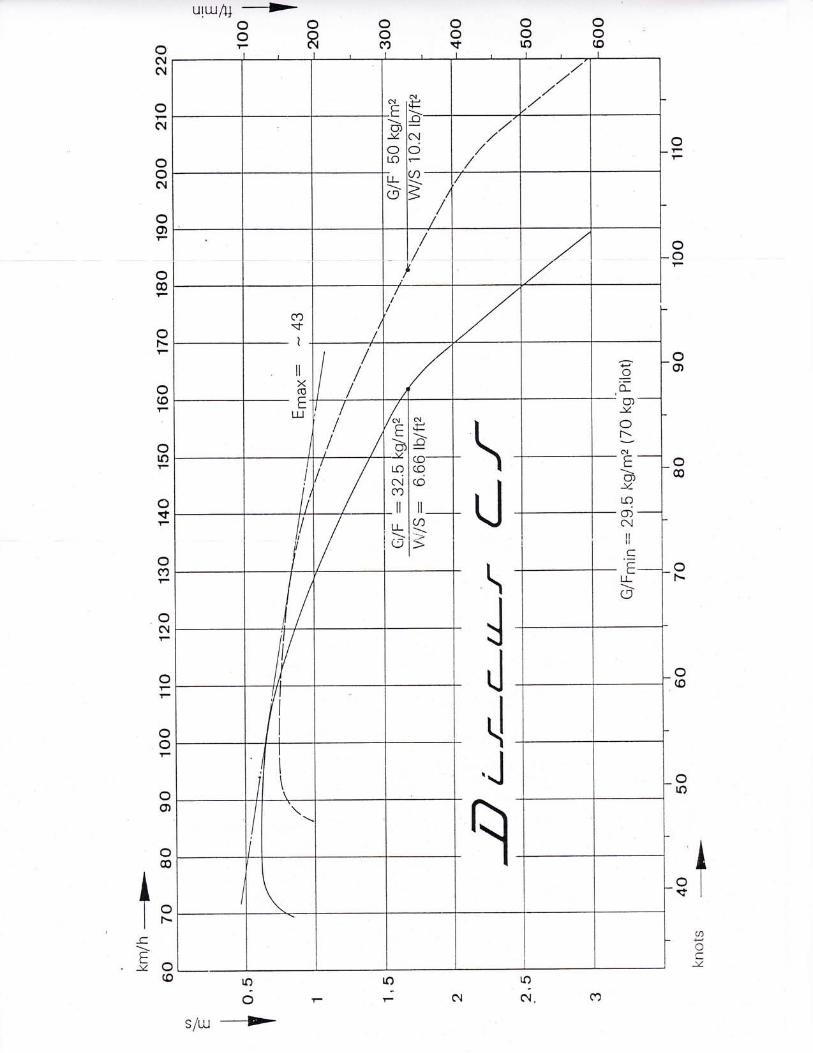
Perforrnance data
F1lght performance data shown refer to an all-upweight of 3so kg (772 lb).
A speed polar dJ-agrarn of Discus CS Ls shown on thenext page.
June 1990
Perfornance
Wing loading 33 kg/mz 6.76 Lb/rt2
Stalllng speed 69 kmrzh 37 kt 43 mph
Minlrnun sLnk rateat veloclty
0 . 61- n/s 1 20 f t,/mln78 km/h 42 kt 48 mph
llaxlmum gllde ratloat velocJ-ty
42.210o kn/h 54 kt 62 nph
o@
IloIr.-
ctrno
(o
ilxCO
?:=o-o)llONc{E(f)
-v_
qNilI
.CE
LL(9
Iolarl
IoC
rO
os/u
-F-