2o 7 sudget. paperwork reduction project (0704-0188 ... classification 19. ... boundary...
TRANSCRIPT

1 ~REPORT DOCUMENTATION PAGEFomApveF I OMB No. 0704-0188
in Is estimtdt vrg I hour per respos including the time for reviewing Instructions, searching existing data sources,Aoeting an=rviwig=h collection fifoation. Send comments regarding this burden estimate or any other aspet otreucngthis burden. to Vlshington Headquarters Services, Directorate for Informnation operations end Reports 1215 Jfferson
an oteOffice of Management and Sudget. Paperwork Reduction Project (0704-0188), Washington, DC 205032O 7 L Report Date. 3. Report Type and Dates Covered.
AD-A 33 ii Jurna Artcle S. Funding Numbers.
Clay Fabric of Gassy Stuarine Sediments PormEeetN-613
________________________________________________________ Project No. 032056. Author(s).
W. A. Chiou, William R. Bryant, and Richard H. Benntett Task No. 330
Accession No.DN257003
7. Performing Organization Name(s) and Address(es). 8. Performing OrganizationNaval Oceanographic and Atmospheric Research Laboratory Report Number.Ocean Science Di rectorateStennis Space Center, MS 39529-5004 JA 360:010:90
9. Sponsoring/Monitoring Agency Name(s) and Address(es). 10. Sponsoring/Monitoring Agency
Naval. Oceanographic and Atmospheric Research Laboratory Report Number.
Ocean Science Directorate JA 360:010:90Stenntis Space Center, NS 39529-5004
11. Supplementary Notes.
1NFS
12a. DistributionlAvallabllity Statement. 12b. Distribution Code.
Approved for pubtlc release; distribution is unlimited.
13. Abstract (Maximum 200 words).The primary objective of this research was to delineate clay fabric microfeatures in sediment samirpes obtained by theuse of a pressure core barrel. A secondary objective was to evaluate the difference in clay fabric between pressure'core barrel surptes and conventional. core samrples, and to enhance the unmderstanding of the clay fabric of fine-grained gassy sediments.
APR 01 1991
14. Subject Terms. 15. Number of Pages.
(U) Sediment Transport; (U) Sedimenits; (U) Pore Pressure; (U) Clay 2016. Price Code.
17. Security Classificastion 18. Security Classification 19. Security Classification 20. Limitation of Abstract.of Report. of This Page. of Abstract.Unclssiffied Unclassified Unclassified SAR
N"N ?U -0W Standard Form 298 (Rev. 2-89)Prescrbed by ANSI Bid. Z39-1691 3 120o05 MW.102

Reprinted from
Richard H. Bennett, William R. Bryant, and Matthew H. HulbertEditors
Microstructure of Fine-Grained Sediments© 1991 Springer-Veriag New York, Inc.Copyright is not claimed for chapters authored by U.S. Government employees (2, 6, 14, 15, 20, 44, 47, 48, 52, 58).Printed in United States of America.
,.., : '*'; ,-Q i
t -' .... ~ ~ .......... ........
Springer-V erlag c. ................................................New York Berlin Heidelberg London ti
Paris Tokyo Hong Kong Barcelona
, J1 ;pca
....s
CHAPTER 37
Clay Fabric of Gassy Submarine Sediments
W.A. Chiou, William R. Bryant, and Richard H. Bennett
Introduction scientists, and geologists. A very comprehensive and informa-tive literature review tracing the history of clay fabric study,
Objectives from early concept through current knowledge to the future per-spective, has been published by Bennett et al. (1977) and Ben-
The primary objective of this research was to delineate clay nett and Hulbert (1986). Moon (1972) also reviewed some of thefabric microfeatures in sediment samples obtained by the use of early clay fabric concepts, particularly in the microstructure ofa pressure core barrel. A secondary objective was to evaluate the fresh clay and compacted clays. A large collection of differentdifference in clay fabric between pressure core barrel samples soil fabrics accompanied with a comprehensive review andand conventional core samples, and to enhance the understand- description of sample preparation techniques, including tech-ing of the clay fabric of fine-grained gassy sediments. niques for quantifying the results was published by Smart and
Tovey (1981, 1982).During the last 15 years, due to the realization that the fabric
Historical Review and Previous Works of a clay fundamentally affects a soil's mechanical behavior, andto the availability of the electron microscope as a tool to study
Geologists have long been interested in the fabric of sediments, clay microfeatures, research on clay fabric has been gainingin particular the fabric of clastic sediments, but chiefly on large momentum significantly. Excellent studies were presented atgrain-sized particles such as sands, gravels, and tills. Study of several international meetings, such as the Southeastern Asianthe fabric of fine-grained argillaceous sediments has been in Conference on Soil Engineering in 1970 and 1971, the Roscoeabeyance due to the extremely fine texture and complex compo- Memorial Symposium (Parry, 1971), the Third Internationalsition of these sediments, and the necessity of high-resolution Conference on Expansive Soils in 1973, the International Sym-techniques to delineate individual particles. Although Henry posium on Soil Structure (Barden and Pusch, 1973), the FourthClifton Sorby, the father of sedimentology, presented the first International Working-Meeting on Soil Structure (Rutherford,microscopic study of rocks by means of thin section as early as 1974), a symposium held at the Third Meeting of Geological1851, it appears to be true, as Burnham (1970) stated, "Many Societies of the British Isles (Whalley, 1978), and the 8th Inter-geological authors ... have been content to describe the large national Clay Conference (Schultz et al., 198/). Papers pre-particles, and to dismiss the finer materials as a featureless inter- sented in these meetings demonstrated the significance of usinggranular paste of very finely crystaline materials." electron microscope techniques, and the important role that clay
The early interest in clay fabric study arose from attempts to fabric plays in the mechanical behavior of soils.determine the relationship between clay particle arrangement The published record contains few reports of studies dealingand the mechanical properties of soil. The early concepts of clay with the fabric of natural sediments in contrast to numerousfabric were conceived by Terzaghi (1925), Goldschmidt (1926), studies of laboratory-prepared sediment samples. The usc ofand Casagrande (1932). Since then, clay fabric research has laboratory-prepared pure clay specimens with different micro-been carried out sporadically primarily by civil engineers, soil fabric features could lead to misinterpretation of the mechanical
333

334 W.A. Chiou, W.R. Bryant, and R.H. Bennett
behavior of natural soils (Collins and McGown, 1974). Further- Floccule or floc: A well-defined clay aggregate composed ofmore, during the past few years, several geologists have begun to several particles or domains having spatial arrangements and par-focus their attention on the relationships between clay fabric and ticle contacts that produce relatively large intravoids relative todepositional environments (O'Brien and Hisatomi, 1978; Ben- the thickness of the individual particles that compose the flocnett et al., 1977, 1980; Chiou et al., 1980; O'Brien et al., 1980; (Bennett et al., 1977). In general a floc consists of a very porousShephard et al., 1980, 1982), particularly in solving sedimen- network of randomly oriented clay flakes or clumps of flakes.tary facies problems. Thus, it is important that specific, quan- Also, it may be composed of numerous face-to-face flocculatedtitative studies on natural sediments from different environ- flakes arranged in a cluster in a stairstep fashion (O'Brien, 1971).ments be carried out to fully understand the nature of the fabric Chain: A series of clay particles or domains that link togetherin a natural environment. However, due to the limitations of in stepped face-to-face and/or edge-to-edge contact (Bennett etboth coring devices and laboratory instruments, undisturbed al., 1977). Chains normally appear to be long and continuous. Aclay fabric has been difficult to obtain. This is especially true for three-dimensional network of twisted chains of clay plateletsdeeply buried, gassy sediments in which clay fabric may have having a stepped face-to-face association is termed stairstepchanged due to the release of hydrostatic pressure. Thus, it is cardhouse fabric (O'Brien, 1971).important to determine the clay fabric of gassy sediments that Particle: A well-defined entity that is resolved by electronhave not been affected by the loss of downhole pressure, and to microscopy. It can be a single clay platelet or several plateletscompare these results with those of studies performed using con- forming a domain. The particle can be thought of as the elemen-ventional methods. tary unit or building block of clay fabric (Bennett et al., 1977).
All the terms described here and applied in this research arestrictly descriptive and do not imply mode of formation.
Theoretical Considerations
Definitions and Terminology Assumptions
Clay fabric research involves sampling, sediment drying,As a result of the increasing number of clay fabric studies in dif- embedding, ultrathin sectioning, and the use of various electronferent scientific disciplines, and the broad variety and complex- microscopy techniques. Due to the soft gassy nature of the sedi-ity of fabrics that have been observed, there has been a prolifera- ments in question and some inherent limitations of the tech-tion of terms for the description of fabrics and fabric features. To niques, several assumptions must be made:prevent an overlap in meaning of terms with previous investiga-tors, a brief explanation of a few key terms is given herein, and 1. No mineralogical changes result from the slight temperaturewill be used in presentation of the results and interpretations in but relatively low pressure change and the substitution ofthis report. interstitial water with different fluids (ethyl alcohol and amyl
Clay fabric: Fabric, as used by sedimentary petrologists, refers acetate) during the replacement process prior to critical pointto "the orientation in space of the elements of which a sedimen- drying. Studies reported by Range et al. (1969) and results oftary rock is composed" (Gary et al., 1972). A fabric element of mineralogical studies by the author from Lee (1980) havea sedimentary rock may be a single crystal, a detrital fragment, demonstrated the stability of clay minerals under similar tem-a fossil, or any component that behaves as a single unit with peratures and pressures as used in this study.respect to an applied force (Fairbairn, 1949). Thus, fabric con- 2. No significant fabric changes result from the build-up of pres-stitutes three-dimensional patterns in space, and includes factors sure in the critical point-drying chamber or high local pres-such as packing, boundary relationships, discontinuities, grain sure in the specimen. To prevent this type disturbance, thesize, or the presence or absence of a matrix, shape and round- final stage of the critical point-drying procedure was per-ness of particles, and orientation. In this study, the fabric ele- formed very slowly as suggested by Tovey (1970) and shouldments are composed mainly of clay-size particles (<4 Arm). have little effect on fabric features (Tovey and Wong, 1973,Thus, clay fabric refers here to the spatial distribution, orienta- 1978; Wong, 1975; Smart and Tovey, 1982).tion, and particle-to-particle relationships of the. <4-1gm solid 3. No fabric disturbance results while substituting interstitialparticles (mainly clay minerals) in the sediment (Bennett, 1976). water with ethyl alcohol, amyl acetate, and liquid CO, before
Domain: A stack of face-to-face or slightly stepped face- critical point drying.to-face parallel clay plates (Aylmore and Quirk, 1960, 1962; 4. Little compression occurs between the diamond knife andBennett et al., 1977). It is essentially the same as the so-called specimen (i.e., no plastic deformation occurred) while ultra-book or packet structure of Sloane and Kell (1966). An array thin sectioning the specimen. Any possible disturbance byof such aggregates is referred to as turbostratic fabric (Biscoe compression has been minimized by adjusting the sectionand Warren. 1942; Olsen, 1962). Yong and Sheeran (1973) condition (specimen position, cutting speed, diamond knifedescribe the grouping of domains or aggregates into larger fabric position, etc.) and by applying xylene vapor over the ultrathinunits as clusters. sections to relieve any possible compression.

37. Clay Fabric of Gassy Submarine Sediments 335
89050' 8940' 893020 89 0'............. ..
*NN
o (
-0"""0
NHod of
Bl-AA
n N
0 40
N g89°50 ' 89o40 , 89o30 , 89o20 , 89°10 '
III I
Figure 37.1. Index map showing sampling site locations.
5. No fabric disturbance results from the possible difference phy and Department of Civil Engineering of Texas A&M Univer-between the measured downhole pressure and actual in situ sity. Detailed specifications and procedures for this samplingpore pressure if excess pore pressure existed. It has been device are presented by Denk et al. (1981).assumed that the difference between in situ total pore water Essentially, this coring device seals sections of sedimentspressure and the measured downhole pressure was insignifi- in a core barrel and retains the sediment at its in situ down-cant in terms of fabric changes. hole pressure. For further protection against pressure loss,
6. No electron-optical or subsequent optical distortion of the downhole pressure is applied to the interior of the core barrelimage in the measurement and calculation of clay fabric during withdrawal from the bore hole. This pressure is deter-orientation analysis exists, mined after the sample had been taken by applying helium gas
pressure through a tube inserted into the interior of the corebarrel just above the sample tube. Using a pressure regulator,
Materials and Experimental Methods the gas pressure is increased until a no-flow condition existsas indicated by a precise flow meter in the line. At this point
Sample the applied gas pressure just balances the downhole pressure(Denk et al., 1981). The sample should be maintained at the
General in situ pressure, but in reality, the pressure being maintainedmay well be that of the column of drilling fluid. The in situ
Samples studied in this research were obtained using a "pressu- downhole pressure on the cored sample was maintained duringrized core barrel" sampling device that was developed at the transport from the field to the laboratory and storage untilMarine Geotechnical Laboratories, Department of Oceanogra- laboratory analyses were made.

336 W.A. Chiou, W.R. Bryant, and R.H. Bennett
Table 37.1. Location and general information of sampling sites.*
Sample depth Measured downholeLocation Water depth below mudline pressure
Sample no. Core no. Latitude Longitude (W) (ft) (W) (ft) (kPa) (psi)
I B-IA 28°52'54" 89°2839" 21 69 4.9 16 324 472 B-IA 28°52'54 " 89°28'39" 21 69 7.9 26 365 533 B-IA 28°5254 " 8902829" 21 69 11.3 37 395 574 B-2 28°54'!3" 89*30'1Y0" 38 125 2.7 9 434 635 B-2 28°54'13" 89°30'!0' ' 38 125 5.8 19 483 706 B-2 28°54'13" 89°3010" 38 125 8.8 29 510 747 B-2 28°54'13 ° 89°30'10" 38 125 11.9 39 559 81
*The Lambert coordinates of Core B- I A: X = 2,594,001; Y = 82,970.The Lambert coordinates of Core B-2: X = 2,585,823: Y = 90,832.
Location fluid before critical point drying under equivalent in situ down-hole pressure, was constructed. The detailed description of theThe samples used in this study were obtained from an area spcaaprtuanpoedesfdyigscmnswe
located offshore Louisiana near the mouth of Southwest Pass spcaaprtuanpoedesfdyigpcmnsweloctedn ofhe isia neltar thmpex moh o. SThes anss presented in earlier papers (Chiou, 1980, 1981). Critical point-within the Mississippi Delta complex (Fig. 37.1). The locations, dried specimens were then embedded with a very low viscosity
water depth, sample depth, and measured downhole pressure of didseieswr hnebde ihavr o icsteatrcdeh , sample ep, ind mle p e 1. epoxy resin (SPURR) under vacuum, cured, and ultrathin sec-each sample are given in Table 37.1. tioned (800-1000 A thickness) with a diamond knife on a Sor-
vail MT-2 ultramicrotome for transmission electron microscopyGeological Background (TEM) study. Detailed techniques of specimen embedding, thin
The birdfoot deltaic complex of the Mississippi River is situated sectioning, and ultramicrotoming, and electron microscopyon the continental shelf offshore Louisiana. The delta front [both TEM and scanning electroa microscope (SEM)] observa-
represents the most recent area of deltaic sedimentation. Sedi- tion were presented by Bennett et al. (1977), Baerwald et al.ments are prograding seaward depositing clays and silty clays in (this volume), Chiou (1981), and Chiou et al. (this volume).the prodelta environment. During the past three decades, the To evaluate the difference in clay fabric between pressuregeology, clay mineralogy, geochemistry, and geotechnical core barrel samples and conventional core samples, sedimentsproperties of these Mississippi deltaic sediments have been adjacent to those selected for the proposed pressurized clayextensively studied. The present delta is probably one of the fabric study were depressurized and then prepared at ambientmost thoroughly investigated marine environments in the world, pressure and analyzed by the same method (as that used for pres-Broad and extensive literature reviews of previous work in the surized samples).Mississippi deltaic complex can be found in Shephard et al. To ensure a more comprehensive and representative study of
(1979), Trabant and Bryant (1979), and references cited in these clay fabric sediment, specimens were cut as shown in Figurereports. Nevertheless, the only clay fabric research that has been 37.3, so that the clay fabric of sediments could be viewed fromcarried out in the Mississippi Delta area was performed by different orientations of the sample relative to the core, i.e., sideBowles, et al. (1969) and Bennett and associates (Bennett and (thin sectioning parallel to core axis, A in Fig. 37.3), top (thinBryant, 1976; Bennett et al., 1977, 1979; Bohlke and Bennett, sectioning normal to core axis, B in Fig. 37.3), and random (C1978, 1980). in Fig. 37.3). However, it was very difficult to maintain the pre-
cise orientation of ultrathin sections because of the difficultiesencountered during sample preparation such as subsampling,
Clay Fabric Analyses embedding, and ultrathin sectioning. The orientation of ultrathinsections given here is thus rather rough, and is only an approxi-
Sample Preparation mate orientation at best.
The most critical steps in preparing samples for electronmicroscopic studies are the techniques employed in the dehydra- Orientation Analysistion of wet specimens and the process of embedding a specimenwith an appropriate medium. The orientation of clay particles was based on the measured
To accomplish this study, a special apparatus, "pressure yes- elongation direction of grain projection. To provide the simplest,sel" (Fig. 37.2) for replacing interstitial water with intermediate fastest, and most accurate measurement of fabric orientation,

37. Clay Fabric of Gassy Submarine Sediments 337
G AXIS of COREa - -C.A.
A200% EthylAlcohol
G b
C.A. -a
BG b
C.A. a
A Chemical VesselC B : Specimen Vessel
C : Drainage Vessel Figure 37.3. Schematic diagram showing the viewing orientation of embedded
G : Pressure Gauge specimen. (A) Side or parallel to core axis view. (B) Top or normal to core axisb Cview. (C) Random view.
C.A.: Compressed Aira, b : Valve
AgNO3 Test The capital letter without parentheses following the samplepostfix indicates the orientation of the thin section observed in
Figure 37.2. General arrangement of pressure vessels for substituting sediment the transmission electron microscope. For example, sample #1interstitial water with intermediate fluid. (A)-B means that this is the sample number 1 (Table 37. 1) that
was prepared following the new technique described in Chiou
the point counting method was used in this study. The detailed (1980, 1981) and the picture is viewed from the top of the core,counting technique followed those of Chiou (1981) and Chiou et i.e., the ultrathin section was cut perpendicular to the sedimental. (this volume), column (or the axis of the core).
In addition, due to experimental failure, some samples mayhave the capital letter F behind A, i.e., (A-F), which means
Designation of Sample Number the proposed (A) method failed to work correctly due to an
accident. Where the technique has not been completed suc-Different processing procedures and variations in sediment cessfully, the reasons for failure and the treatment after failureorientation for ultrathin sectioning necessitated a systematic will be described.designation of sample number. Samples designated with postfix(A) were prepared and dehydrated using the new techniquedescribed herein (i.e., sample dehydration was carried out Resultsentirely under the equivalent in situ downhole pressure). Samplepostfix (B) was designated for samples that were dehydrated Lithology and Grain Size Analysisonly partially under equivalent in situ downhole conditions, i.e.,after changing the samples' interstitial water with absolute ethyl The general lithology of the cores used in this investigation andalcohol. The samples were then exposed to ambient pressures. the results of selected geotechnical property tests are shown inSample postfix (C) was designated for samples that were Figures 37.4 and 37.5.dehydrated after in situ downhole pressures were released, i.e., The results of grain size analyses were performed at the samethe conventional method as described by Bennett et al. (1977). time the sample was fractionated for the clay mineralogy study,

338 W.A. Chiou, W.R. Bryant, and R.H. Bennett
Table 37.2. Bulk mineralogy percentages (%) in the total sediments of boreholes Table 37.3. Qualitative and semi-quantitative analysis (relative %) of clayB-IA and B-2 samples. minerals in sediments of boreholes B-IA and B-2 from the Mississippi Delta.
Core no. Sample no. Quartz Feldspars Calcite Dolomite Clays Size fraction
B-IA 1 56 15 I 2 26 (lpm) Sample no. Smectite Chlorite Illite Kaolinite2 56 13 1 2 28 <0.2 I 45 1 48 63 47 16 1 3 33 2 50 1 42 7
B-2 4 57 13 2 3 25 3 50 1 45 45 47 12 1 2 38 4 46 1 48 56 47 11 1 3 38 5 52 1 43 47 47 I1 I 2 39 6 48 1 45 6
7 49 1 44 62-0.2 1 7 8 56 29
thus no further subdivision of the presented grain size classifica- 2 7 Ii 63 193 6 7 64 23
tion was deemed necessary. Nevertheless, most of the sediments 4 6 7 60 244 6 10 60 24
displayed a bimodal distribution with the strongest mode at the 5 17 6 60 17medium and fine clay particles (s _2 pm) and the second mode at 6 12 8 60 20both coarse silts and medium-grained silts (62.5-5 gm). 7 19 5 58 18
The major constituent of all samples analyzed in this study is 5-2 I 3 14 66 172 3 14 66 17
clay size (<2-pm fraction), particularly less than 0.2-pm frac- 3 12 70 173 1 12 70 17
tions. The amount of the <0.2-pm fraction increases with 4 3 14 66 17depth, from 33.8 to 40.2% in borehole B-1A and from 35.2 to 5 4 12 72 1246% in borehole B-2, although the percentage of coarse clay 6 3 13 68 16(2-0.2 pnm) fraction remains rather constant (10.7-14.2%) in 7 2 15 66 17sediments from both cores. The weight percent of total silts(coarse, medium, and fine silts) is nearly equal to that of totalclays. The major constituent of the silts was quartz. The sand- in the sediments studied The major clay minerals identified insize fraction was generally a very minor constituent (< 1%) of the 5- to 2-gm fractions were illite (66-72%), kaolinite (12-17%),these sediments and was composed mainly of quartz with minor chlorite (12-15%), and smectite (1-4%). The clay minerals in theamounts of feldspars or shell fragments. 2- to 0.2-gm fractions were composed mainly of illite (56-64%)
The grain size analyses results parallel those Scafe's (1968) with fair amounts of kaolinite (17-29%) and small amounts ofreport (sample 64-A-6 #1). His results also depicted the unifor- chlorite 5-11%) and smectite (6-19%). The less than 0.2-pm finemity of grain size distribution. Similar homogeneity of minera- fraction of these sediments contained primarily smectite (46-logical constituents also was found in these sediments. This will 50%) and illite (42-48%) with very small amounts of kaolinitebe discussed in the following sections. (4-7%) and trace amounts of chlorite (1%).
The semiquantitative nature of estimating mineralogical com-position and the fact that all calculations are based on 100% clay
Mineralogical Analysis in each sample should be kept in mind. These percentages are
Bulk Mineralogy difficult to compare with the results of previous investigationssince only clay minerals in the less than 2-pm range are reported
The bulk analyses (Table 37.2) show a uniform distribution of in the literature. However, a comparison of the relative percen-mineral constituents in sediments throughout the two core sam- tage of clay minerals downhole is useful. In this study, it showspies. Quartz decreases slightly (approximately 10%) with depth. that illite was the dominant mineral in the coarse and mediumClay minerals range from 25 to 39% and increase slightly with clays. Percentage of kaolinite and chlorite also decreases as graindepth. Small amounts of feldspars (11-16%), and trace amounts size decreases. Smectite was thc predominant species in the lessof dolomite (2-3%) and calcite (1-2%) were also present than 0.2-pm clays. This result agrees with the general relation-throughout the cored sediments. ship between clay particle size and clay mineral species.
Clay MineralogyClay inerlogyClay Fabric AnalysisAlthough the clay mineralogy in the Mississippi Delta has beenextensively studied, no study has been reported in any great Method (A)detail. To understand the relationship between clay fabric andclay mineralogy, detailed clay mineral analyses of different size Clay fabric samples prepared using the new method, i.e., down-fractions were performed. The results of clay mineral analyses hole pressure maintained until the sample was critical point dried,(Table 37.3) indicate a fairly uniform distribution of clay minerals are characterized by relatively well-oriented clay particles or

37. Clay Fabric of Gassy Submarine Sediments 339
Boring I , Block 85 * Submerged Unit Undrained ShearWest Delta Area I - Weight , PCF Kips Per S . Ft
Seotloor at EL-69' - 30 40 0.05 0.10 0.15 0.20Very soft dart gray cloy - U
-with black seoms,2l to 41' ' de1 0-expansive, 12' to 41' and below 65'-gassy,6 to 29' and below 70' C
-orgonc odor, 12' to 14' 13 0 00
SAMPLE No. 1 -47- 5
1312 0 Qc
3 0 wI-' I-II- SAMPLE No.2 -53- JlI
oj a30 - 0,
0 0a: SAMPLE No. 3 -57-- 00 -with block and olive gray streoks Is 0 0
40 39' to 41' - .
IL 4IUJ U)
U)50- 0 e -1
60
80 20
70- - - - - -2
* MINIATURE VANEo TORVANE0 CONSOLIDATED UNDRAINED TRIAXIAL (Remolded Tests)
Figure 37.4. Profiles showing general lithology and results of field tests from boring 1.
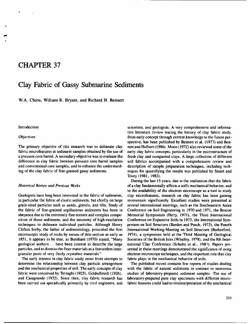
domains, with random structures occurring only locally (Figs. SEM micrograph, and, thus, the best way to perform an orienta-37.6 through 37.8). Domains are composed of face-to-face tion analysis is on a TEM micrograph.(or side-by-side) clay platelets forming a nearly perfect stack.The domains appear to vary over a considerable range of size, Method (B)but most of them are relatively large. Large voids are clearlydepicted between clay particles or domains. These voids could If the in situ downhole pressure was released before completehave been occupied by gases and/or interstitial waters. Some dehydration of the sediment, the clay fabric appears from semi-clay particles are also aligned step-by-step, forming either oriented to fairly nonoriented microfeatures. Although electronshort or long chains. Although some random arrangements microscopy observations show that some samples contained bothare also shown in the TEM observations, it appears that clay oriented and random microfeatures, it appears that the randomparticles are predominantly aligned in a preferred orientation. A microfeatures were predominant in most cases. TEM micrographstypical rose diagram of clay particle orientation and narrowly (Figs. 37.9 and 37.10) reveal numerous edge-to-edge contacts ofdistributed clay orientation frequency curve, as shown in clay particles, and the size of individual domains decreases. ManyFigures 37.6 and 37.7 reveals the statistical calculation of well- of the particles seen in the micrographs do not appear to be in con-oriented clay fabric. tact with other particles, but seem to be "floating" in space. Thus,
Scanning electron micrography observations (Fig. 37.8) also large voids are revealed in the micrographs. However, the micro-reveal fairly well-oriented nature of clay platelets although some feature is being observed in two dimensions, and the point con-may not show as distinctly as those in TEM micrographs. It is tacts are either above or below the plane of the ultrathin sections.obvious that the entire orientation is difficult to determine on a The clay particle orientation diagram depicts a random arrange-

340 W.A. Chiou. W.R. Bryant. and R.H. Bennett
Boring 2, Block 85 Submerged Unit Undrained ShearWest Delta Area WeigStrengthW D, Kips Per Sq. Ft.
0 Sfloor Ot EL-125' 30 40 0.05_0.10 0.15Vary soft to soft dark gray cloy Ui U 0
with organic odor to 2'OUl$nsiv and gassy to 104'
very soft to 125'10 with *and seams 3' to 5
SAMPLE No. 4 -63-with block streaks 15' to 17', 125' to127' and 150' to 152' 0 0 5
20 SAMPLE No.5 - 70-1
0 U)a, o wJ
SAMPLE No.6 174-
W 30 W10
ISAMPLE No.? 0
-8
0: 40 W_ -
0 00 a 0 0
W 50 - :15 w
60-
0
70 0 20
oo
60
so 0
90
* MINIATURE VANEo TORVANE0 CONSOLIDATED UNDRAINED TRIAXIAL (Remolded Tests)
Figure 37.5. Profiles showing general lithology and results of field tests from boring 2.
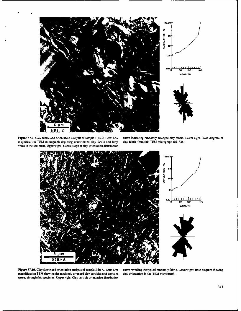
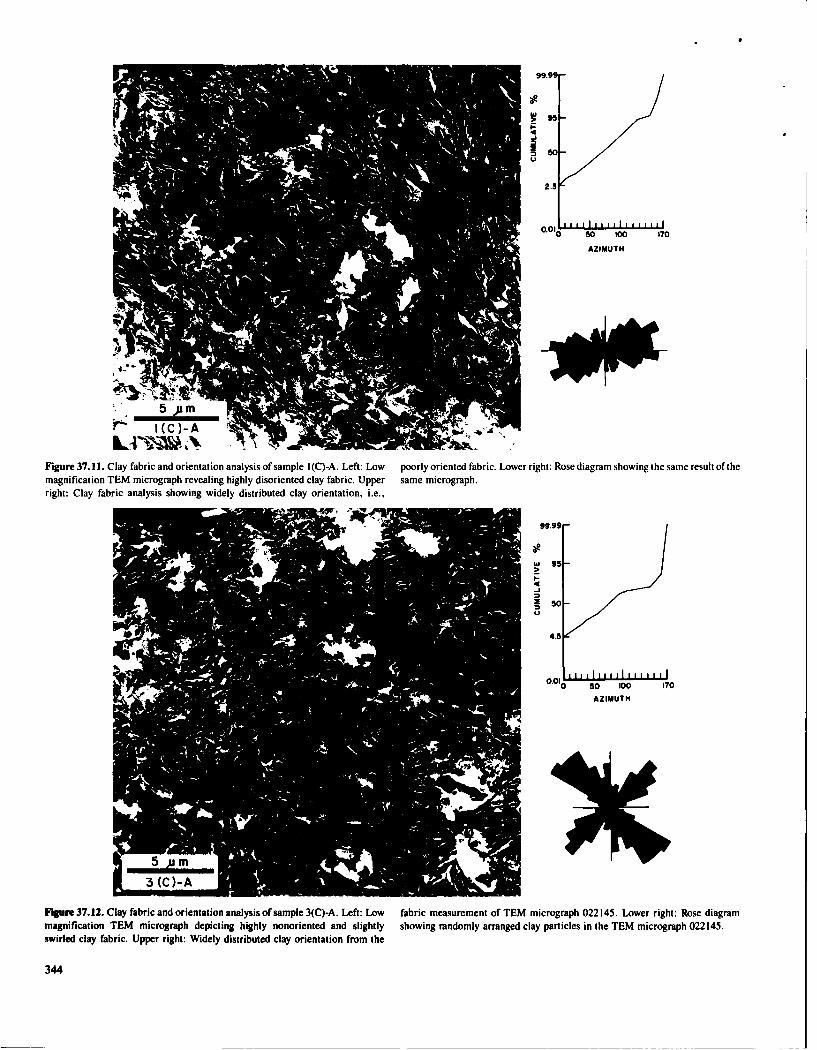
ment, and the corresponding frequency curve also shows a artificial). A few large "pocket-like" pore spaces are present aswidely spread orientation spectrum. are some void spaces of possible organic origin (Fig. 37.14).
These pocket-like pores may represent the gas expansion dueMethod (C) to depressurization of the specimen. Other interesting features,
e.g., slight "swirl" pattern and some "doughnut-like" clay fabric,Clay fabric samples prepared using the conventional method, have been observed in these specimens. A typical orientationi.e., the downhole pressure was released before any process of diagram and frequency curve (Figs. 37.11 and 37.12) illustratedehydration of the sample, are typified by a highly random the highly random clay particle arrangement. The SEM micro-arrangement of clay particles or domains (Figs. 37.11 through graphs also show similar clay microfeatures (Fig. 37.13).37.14) although in some areas preferred orientations are ob-served. Many particles appear to be "floating" in space and large Method (A-F)void spaces are present. Void spaces appear to be very well con-nected. In some cases these void spaces are wide enough to form Two types of interesting phenomenon were observed in thea "channel-like"' feature. Although these channel-like features experiments. In two cases, samples 2(A-F) and 7(A-F), samplesmay be due to irregular fracturing of the sample during prepara- during dehydration process were accidentally degassed for abouttion, they still indicate some type of discontinuity (natural or 10 sec and 45 min, respectively, the clay fabric observed in EM

99.99
w95-
S50-
3
0160
AZIMUTH
Figure 37.6. Clay fabric and orientation analysis of sample 1 (A)-A. Left: Low (shown by arrow) represent pore spaces of the specimen. Upper right: Narrowlymagnification TEM micrograph showing preferentially oriented clay particles distributed clay particleorientation. Lower right: A rose diagram revealing welland domains. The white areas (A) represent artifact "holes:' The gray areas oriented clay fabric.
99.99
0-
0.7
0 50 100 140
3 (AI-A
Figure 37.7. Clay fabric and orientation analysis of sample 3(A)-A. Left: Low rowly distributed orientation spectrum. Lower right: Rose diagram showing claymagnification TEM micrograph showing the preferentially oriented clay fabric, orientation in the TEM micrograph.Upper right: Clay particle orientation frequency distribution curve showing nar-
341

342 W.A. Chiou, W.R. Bryant, and R.H. Bennett
arranged clay domains and clay platelets as compared to theothers, even though some areas may consist of mixed microfea-tures (Figs. 37.17-37.19). Fairly large void spaces and otherswirl and channel-like features are also present. The frameworkof clay fabric in these long degassed samples is similar to thoseprepared by method (C).
Discussion
The Sediment
Based on the grain size, bulk mineralogy, and clay mineralogyanalyses, the constituents of the sediments were the samethroughout the two cored sections, although sample Nos. 1, 2, 4,
1(A and 6 showed a slightly higher weight percentage of coarse silt
b fraction than the others. Neither grain size analyses nor bulk andclay mineralogical analyses showed significant variations inthese samples. The grain size distribution and mineralogicalcomposition of the seven samples were very uniform, and thesediment can be classified as silty clay or mud (Folk, 1974).
There are several factors, both physical and chemical, that caninfluence fabric microfeatures of a clayey sediment. In thisstudy, the physical factors such as grain size, bulk mineralogy,clay mineralogy, rate of deposition, and depth of burial (in situdownhole pressure or effective pressure) were taken intoaccount. Because of sediment uniformity in the relatively shortcores, and the high deposition rate during Pleistocene time, thesediment can be considered as being homogeneous. The clayfabric in the different samples discussed has been subjected tosimilar geological conditions and the relationship between theclay fabric and the effects of the in situ downhole pressure on the
Figure 37.8. Clay fabric of sample I(A). Top: SEM micrograph showing the sediment can be compared.porous nature of the sediment in low magnification. The oval-shape depressionis thought to be created by a large gas bubble. Bottom: SEM micrograph showingwell-oriented clay fabric from the wall of the gas bubble-like depression. Comparison of Clay Fabric Using
Conventional and New Techniques
study appears to be preserved fairly well. At low magnifica- The clay fabric of samples prepared by method (B) or (C) of thistion clay particles are aligned in a general direction. Clay research was similar to the previous studies of Mississippi Deltaorientation and frequency distribution curves also indicate the sediments (Bowles, 1969; Bowles et al., 1969; Bennett et al.,material consists of fairly well-oriented clay particles over a 1977; Bohlke and Bennett, 1980). Bennett et al. (1977) foundrelatively wide angle range. However, in some areas of the thin random arrangement of clay particles predominating over thesection, the clay fabric shows slightly random arrangement. greater portion of the ranges in void ratio in shallow buried sedi-Figures 37.15 and 37.16 illustrate these combined features. It ments in the northwestern Gulf of Mexico and the Mississippialso was found that clay fabric near large pore spaces seems to Delta. Bennett did not encounter noticeable preferred particlelie more randomly. In general, results of these two samples show orientation in sediments buried less than 100 m in the Missis-mixed microfeatures of fairly oriented with some slightly ran- sippi prodelta. These clay fabric observations appeared similardomly arranged clay fabric, to those in sediments where the in situ downhole pressure was
Samples 4(A-F) and 6(A-F) had been degassed to ambient released before dehydrating the sample. Samples studied bypressure for 2 and 5 hr, respectively, during the dehydration of Bennett had low to negligible gas content, thus, the comparisonthese specimens, although the original in situ downhole pres- of results from this study to those of Bennett's is rather difficult.sures were reapplied after degassing. Both TEM and SEM obser- In contrast, preferred orientation of clay particles was rev-vations of these long degassed specimens show randomly ealed by the new sample preparation method, although the
95-
0-j-
0.6
0 50 100 160
AZIMUTH
J J- C .
Figure 37.9. Clay fabric and orientation analysis of sample 1(B)-C. Left: Low curve indicating randomly arranged clay fabric. Lower right: Rose diagram ofmagnification TEM micrograph depicting nonoriented clay fabric and large clay fabric from this TEM micrograph (021826).voids in the sediment. Upper right: Gentle slope of clay orientation distribution
0- 95-
S50-
2
0 50 100 170
AZIMUTH
Figure 37.10. Clay fabric and orientation analysis of sample 3(B)-A. Left: Low curve revealing the typical randomly fabric. Lower right: Rose diagram showingmagnification TEM showing the randomly arranged clay particles and domains clay orientation in the TEM micrograph.spread through this specimen. Upper right: Clay particle orientation distribution
343
99.99
50-
00 so 50 0 170
AZIMUTH
5 ym
Figure 37.11. Clay fabric and orientation analysis of sample 1(C)-A. Left: Low poorly oriented fabric. Lower right: Rose diagram showing the same result of themagnification TEM micrograph revealing highly disoriented clay fabric. Upper same micrograph.right: Clay fabric analysis showing widely distributed clay orientation, i.e.,
99.99
w95-
2 500
4.5 l
O iq It lii i ii i0 0 so 00 170
AZIMUTH
FIgure 37.12. Clay fabric and orientation analysis of sample 3(C)-A. Left: Low fabric measurement of TEM micrograph 022145. Lower right: Rose diagrammagnification TEM micrograph depicting highly nonoriented and slightly showing randomly arranged clay particles in the TEM micrograph 022145.swirled clay fabric. Upper right: Widely distributed clay orientation from the
344

37. Clay Fabric of Gassy Submarine Sediments 345
I(C
S(C) Figure 37.14. Clay fabric of sample 6(C)-A (TEM). Top: TEM micrograph9 1 (C ~showing large "pocket-like' pore space. It may be due to the degassing effect.
Figure 37.13. Clay fabric of sample I(C)-A. Top: SEM micrograph of the porous i.e., gas expansion. Bottom: TEM micrograph showing large void spaces. The
sediment. No ditference observed from Figure 37.8a. Bottom: Higher magnifi- lines shown in the large void may be biogenic in origin.cation of the "depression" area of the top micrograph revealing the randomlyarranged clay fabric. pressure core barrel. The release of such a relatively high concen-
tration of gas from the sediment would destroy the equilibriumpreferred orientation was not always perfect in samples sub- system in the sediment matrix. Thus, the clay particles mustjected to lower downhole pressures or effective overburden pres- undergo motion or rearrangement toward a new equilibrium sys-sures. Since most of the clay particles are of plate-like shape, the tem when exerting forces eased (i.e., when the gas or the overbur-clay particles tend to be aligned in a similar orientation due to den pressure was released).the overburden pressure exerted across the maximum surface Shear forces (stresses) exerted on clay particles must bearea of a clay particle (preferential orientation). While in situ, created whenever the pressure changes (degassing) due to thethe overburden pressure (downward) was much greater than (or release of in situ pressure. Consequently, clay particles will beat least equal to) gas pressure (upward). The preferred clay realigned to another stable condition because of this forceorientation thus was maintained, change. The mainly nonoriented but partially oriented clay
According to Whelan et al. (1981), methane concentration mea- fabric as shown in the results of method (B) and (C) prob-sured from the same pressurized core sediments used in this study ably resulted from the shearing stress and rearrangement ofranged from 3450 to 137,140 ppm (gtl CH 4(STP)/iiter wet sedi- clay particles. Similar fabric relationships with regard to shearment). These values are generally higher than values found in stresses and soil deformation have also been discussed bycompanion samples taken with conventional wire-line equipment. Sloane and Kell (1966), Morgenstern and Tchalenko (1967a,b),Their results also showed that at least 98% of the methane was Smart (1967), Pusch (1970), Barden (1972), and Mitchellreleased from the sediment matrix within 3-5 hr after opening the (1976).

346 W.A. Chiou, W.R. Bryant, and R.H. Bennett
99.99-
95-
5/
0 50 00o 170AZIMUTH
2(A-F)-A
Figure 37.15. Clay fabric and orientation analysis of sample 2(A-F)-A. Left: in the central portion (from lower left to upper right) clay has been compressedLow magnification TEM micrographs showing the general direction of clay a little as shown by elliptical-shaped clay aggregate (lower left). Thus, the orien-arrangement although slightly randomly arranged clay fabric occurs in some tation analysis of this micrograph is rather questionable. Upper right: Clay parti-places. The abundant fine silts are also shown in the micrograph. The rather poor cle orientation distribution curve showing the mixed oriented and nonorientedquality of this ultrathin section is mainly due to the large amounts of silt-size fabric pattern. Lower right: Rose diagram showing clay orientation in the TEMgrains. It was also found that areas containing silts were not well impregnated micrograph (022836).with the embedding medium and were therefore torn out (areas A). Clay fabric
The highly nonoriented random microfeature depicted in sam- effects of degassing as a function of time. Samples 2, 4, 6, andpies prepared by method (C) probably represents disturbed 7 offered such an opportunity.microfeatures primarily due to the disequilibrium of sediment Both sample 2(A-F) and sample 7(A-F) were accidentallymatrix by the release of in situ gas pressure. The channel-like degassed for approximately 10 sec and 45 min, respectively, andvoid spaces with randomly arranged clay particles may reflect the clay fabric observed in TEM seems to be preserved fairlythe avenues created by escaping gases. well. On the other hand, samples 4(A-F) and 6(A-F) had been
Similar results between methods (B) and (C) suggest that clay exposed to ambient pressure for approximately 2 and 5 hr,fabric microfeatures of gassy sediment are rather delicate and respectively, and revealed highly random microfeatures showingthat the fabric orientation can be altered if the in situ pressure is the same fabric as from conventional samples 7(C) and 6(C).released before the sediment is completely dry regardless of dry- The degassing effect on disrupting clay fabric is time dependent.ing time. Although it was not possible to study this aspect in detail (i.e.,
degree of clay particle orientation versus length of time ofdegassing, rate of degassing and specimen size), it appeared that
Clay Fabric vs. Degassing ime with a specimen size of 7 x 7 x 20 mm the clay fabric in thecentral portion of a specimen will not be disturbed if the length
During the course of this research, the accidental release of in of degassing time is less than an hour. Of course, it also dependssitu downhole pressure in the exchange Plexiglas pressure vessel on the rate of leaking and gas concentration in the sample. Thisoccurred during the testing of some samples. Although this was observation parallels the methane gas concentration studiesnot the original intent, it did offer an opportunity to examine the made on the saline pressurized core barrel sediments (Whelan

37. Clay Fabric of Gassy Submarine Sediments 347
et al., 1981), which showed that at least 98% of the methane wasreleased from the sediment matrix within 3-5 hr after openingthe pressure core barrel.
The concurrence of well-oriented and highly randommicrofeatures in one sample examined [7(C)] is difficult to inter-pret. They may result from a partially disturbed sample or froman artifact created during sample preparation. Randommicrofeatures observed in sample 2(A-F) at high magnificationprobably indicate slightly degassed sediment near the sampleedge. Clay fabric results of repressurized sediments also demon-strated the principle of clay fabric chemical irreversibility formarine sediment as proposed by Bennett et al. (1977). mI
_FClay Fabric and Shear Strength
One of the major purposes of the pressure core barrel samp.-ling project was to compare the in situ (pressurized) and con-ventional vane shear strengths. To accomplish this, vane shearequipment was taken into a hyperbaric chamber and sheartests were performed while at in situ downhole pressure. Thesame sample was then depressurized in the laboratory andthe shear strength measured again using the same vane shearinstrument.
By comparing both clay fabric and vane shear strength (1)in the hyperbaric chamber and (2) by the conventional method,the important relationship between these features is clearlyshown (Fig. 37.20). Clay sediment with preferred orientationdisplays high shear strength, while clay sediment with random r-, -microstructure has lower shear strength. This observation issimilar to the results presented by Matsuo and Kamon (1973)and Koff et al. (1973). Clay fabric with preferred orientation Figure 37.16. Clay fabric of sample 7(A-F)-A (TEM). Top: TEM micrograph
showing that slightly swirled fabric pattern (center) that occurs in a generallyprovides better sediment integrity and higher shear strength well-oriented clay sediment. Bottom: TEM micrograph showing locallybecause of the greater surface area contact, and higher bonding nonoriented clay fabric and large void spaces. Fluffy appearance (arrow) may beforce. organic in origin.
Conclusions tures of gassy, deltaic sediments are affected by different sam-fabric studies on sediments reco- ple dehydration techniques. The clay fabric reflected by these
Based on the results of clay fbr t uding oncsions rayo- different methods of dehydration can be summarized as fol-vered by the pressurized corer the following conclusions may be lows:
drawn:
1. The results presented in this research demonstrate that the a. The clay fabric of sediments prepared by the new methodpressure core apparatus and pressurized fabric techniques (A) was characterized by relatively well-oriented clay par-were successful. The new method, (method A) in this study, ticles and domains, although random structures may occurwas able to remove gas and dehydrate the wet sediment sam- locally. It appeared that the degree of preferred orientationpies by critical point-drying techniques without noticeably increases with the overburden pressure. The size ofdisturbing the clay fabric microfeatures. Nongassy sediment domains was larger than those prepared by methods (B)does not require the new method (A) described herein, and (C). Chains are well developed and relatively long.
2. The results of detailed investigations of electron micrographs Void spaces are more elongate in shape. Orientation fre-obtained by TEM and SEM observations, statistical calcula- quency curves are narrowly distributed and form a rela-tions, and graphic analyses show that clay fabric microfea- tively steep slope.

99.9
*
250-
2.3
0.01 JLL0 50 tOo 170
AZIMUTH
iMFigure 37.17. Clay fabric and orientation analysis of sample 4(A-F)-A. Left: distribution frequency (top) and rose diagram (bottom) showing the mixed pat-Low magnification TEM micrograph revealing the high void spaces and the clay tern of oriented and nonoriented clay fabric in the TEM micrograph (022866).particles that seem to be floating in the spaces. Right: Clay particle orientation
99.997
95-
450
S 3-
0 SO 100 160
AZIMUTH
FIgure 37.18. Clay fabric and orientation analysis of sample 6(A-F)-A. Left: tions. Right: Clay particle orientation analysis, as shown by orientation fre-Low magnification TEM micrograph revealing the randomly arranged clay par- quency distribution curve (top) and rose diagram (bottom) showing the highlyticles and domains, and somewhat swirled pattern in the studied ultrathin sec- randomly arranged clay fabric in this sample (TEM micrograph 022917).
348

37. Clay Fabric of Gassy Submarine Sediments 349
5pro
4 (A-F)
Figure 37.19. Clay fabric of sample 4(A-F). A mosaic of SEM micrographs giv- clay flakes associated with channel-like features (canyon-like in this micro-ing a general view over a relatively large area. Somewhat oriented clay arrange- graph) meandering through the central portion of the micrograph.ment is shown in upper portion of the micrograph whereas randomly arranged
b. The clay fabric of sediments prepared by method (B) Suggested Areas for Future Researchdepressurized gassy sediment was typified by a randomarrangement of clay particles. Degree of randomness This investigation represents only an initial step toward anseems to decrease with overburden pressure. The size of understanding of the mechanisms that may influence the com-domains was smaller as compared to those of method (A). plex clay fabric microfeatures in gassy, clayey sediments. TheClay particles appear to be floating in irregular void present research has attempted to evaluate the effect of only thespaces. Clay particle orientation frequency curves are physical pressure factor (release of pressure on gassy sediment)widely spread with gentle to low slopes, on the many complex variables that may interfere with the clay
c. The clay fabric of gassy sediments prepared using method fabric of a sediment. During the course of this research several(C) is primarily characterized by highly nonoriented clay areas for future study were identified.particles (except one case in sample no. 1). The fabric 1. How deep or to what depth will clay fabric microfeatures ofappears to result in more randomness than method (B). a gow de nt ill cly fabriclmiofatures-Clay particle orientation frequency curves are widely dis- a gassy sediment still be affected by the release of in situ pres-sure?tributed with a flat or slightly concave shape toward the 2. What is the detailed relationship between clay fabric andlower frequency. degassing time with different sampling (or burial) depth?
3. The comparison of clay fabric microfeatures in different 3. What are some statistical and mathematical technique(s) orstages of sediment degassing shows that the degassing formula(s) that can be developed to describe the relationship
(depressurizing) effect on the clay fabric texture in a sediment between clay fabric and shear strength or other geotechnical
matrix is time dependent. properties?
4. The relationship of clay fabric microfeatures and vane shear Based on the observation of thousands of TEM micrographs,strengths in both in situ pressure and ambient pressure condi- the writers found that if the clay particles in the ultrathintions illustrates the close correlation between these two sections can be identified easily and correctly, clay petrology,important geotechnical properties. Sediment with preferred analogous to clastic sedimentary petrology, sandstone, or car-clay orientation at in situ pressures has higher shear strength bonate petrology, can be developed and applied to the under-than degassed nonoriented clay fabric at ambient conditions. standing of fine grained particles. The most important aspect

350 W.A. Chiou, W.R. Bryant, and R.H. Bennett
21232
999
99.9
99
- 96
64.9psf Pressurized 9o 90 W
-80
70
ROTTIO (Rdio) 60 ZI nc-o 5 - 50
Go- -40
70- -30
so/ - Sample 1 ,(A) -C , 21819 -20
so/ Sampl* 4 1 ,(C) -A , 21232 -t
/ 106
0 20 40 60 s0 100 120 140 ISO O
ORIENTATION (Degree)
21619
Figure 37.20. Comparison of clay fabric and shear strength. Clay fabric and orientation analysis (cumulative orientation frequency curve and rose diagram)
hear strength between pressurized (new technique developed in this study) and indicating wel-oriented clay fabric from the pressurized sample whereas the
degssd (conventional technique) sediment samples. TEM micrograph and degassed sample reveals randomly arranged clay fabric.

37. Clay Fabric of Gassy Submarine Sediments 351
of such a future research area is to improve the software and Bennett, R.H., D.N. Lambert, M.H. Hulbert, H. Schmoll, and B.M. Bohlke,
hardware of the X-ray (EDS) system to become a highly efficient 1980. Clay fabric of sediments from various depositional environments (abs.).
particle composition analyzer, so that the texture, morphology, 29th Annual Clay Minerals Conference, Clay Minerals Society, Waco, TX, p. 22.Biscoe, J., and B.E. Warren, 1942. An x-ray study of carbon black. Journal of
mineralogical, and chemical composition can be studied at the Applied Physics, v. 13, p. 364-371.
same time. Bohlke, B.M., and R.H. Bennett, 1978. Mississippi prodelta crusts: a clayfabric and geotechnical analysis: Phase I report for the U.S. Geological Sur-vey. NOAA, AOML, Miami, FL, 67 p.
Bohlke, B.M., and R.H. Bennett, 1980. Mississippi prodelta crusts: a clayAcknowledgments fabric and geotechnical analysis. Marine Geotechnology, v. 4. p. 55-82.
Bowles, FA., 1969. Electron microscopy of the microstructure in sedimentThis chapter constitutes a portion of the senior author's doctoral samples from the Gulf of Mexico. Ph.D. dissertation, Texas A&M University,
dissertation under the direction of the co-authors. The authors College Station, TX, 113 p.are grateful to Dr. Hilton Mollenhauer (Veterinary Toxicology Bowles, F.A., W.R. Bryant, and C. Wallin, 1969. Microstructures of unconsoli-
dated and consolidated marine sediments. Journal of Sedimentary Petrology,and Entomology Research Laboratory, U.S. Department of Agri- v. 39, p. 1546-1551.
culture) who graciously permitted free access to the transmis- Burnham, C.P., 1970. The micromorphology of argillaceous sediments: particu-
sion electron microscopy laboratory and helped in many ways larly calcareous clays and siltstones. In: Osmond, D.A., and P. Bullock (eds.),
with the electron microscopy study. The authors wish to thank Micromorphological Techniques and Applications. Soil Survey Techniques
the members of Geotechnical Properties Laboratories at Texas Monograph, No. 2, p. 83-96.Casagrande, A., 1932. The structure of clay and its importance in foundation
A&M University, Drs. Wayne Dunlap, Les E. Shephard, engineering. Journal Boston Society of Civil Engineering, v. 19, p. 168-208.
Michael Regan, Elliott Taylor, and Mark Johns, for their gener- Chiou, W.A., 1980. A new technique in preparing in situ marine sediments for
ous assistance in providing and preparing pressurized core clay fabric study. Proceedings of the 38th Electron Microscopy Society of
samples for this research. This chapter has benefitted from dis- America Annual Meeting, p. 204-205.
cussions and reviews with Drs. Les E. Shephard, Louis J. Chiou, W.A., 1981. Clay fabric of gassy submarine sediments. Ph.D. disserta-
Thompson, Thomas R. McKee, U. Grant Whitehouse Ction, Texas A&M University, College Station, TX, 248 p.Chiou, W.A., L.E. Shephard, and W.R. Bryant, 1980. Clay fabric and geotech-
(deceased), Richard Rezak, and David D. McGrail (deceased). nical properties of trench sediments (abs.). 29th Annual Clay Minerals Con-
This research was supported by the National Oceanic and ference, Clay Minerals Society, Waco, TX, p. 28.
Atmospheric Administration (NOAA), U.S. Department of Collins, K., and A. McGown, 1974. The form and function of microfabric fea-
Commerce, and the U.S. Geological Survey (Texas A&M tures in a variety of natural soils. Geotechnique, v. 24, p. 223-254.Denk, E., W.A. Dunlap, W.R. Bryant, L.J Milberger, and T.J. Whelan, 1981.
Research Foundation Project #4076 and 3997). A pressurized core barrel for sampling gas-charged marine sediments.
Proceedings of the 13th Annual Offshore Technology Conference, p. 43-52.Fairbairn, H.W., 1949. Structural Petrology of Deformed Rock.. Addison-
References Wesley, Cambridge, 344 p.Folk, R.L., 1974. Petrology of Sedimentary Rocks. Hemphill Publishing Co.,
Austin, TX, 182 p.Aylmore, L.A.G., and J.P. Quirk, 1960. Domain or turbostratic structure of Gary, M., R. McAfee, Jr., and C.L. Wolf, eds., 1972. Glossary of Geology.
clay. Nature. v. 187, p. 1046-1043. American Geological Institute, Washington, D.C., 805 p.Aylmore, L.A.G.. and J.P. Quirk, 1962. The structural status of clay systems. Goldschmidt, V.M., 1926. Undersolkelser over lersedimenter. Nordisk jour-
Clays and Clay Minerals, v. 9, p. 104-130. brugsforkning, No. 4-7, p. 434-445.Barden. L., 1972. The influence of structure on deformation and failure in clay Koff, C.L., A.S. Polyakov, and E.M. Sergeev, 1973. Changes in microtexture of
soils. Geotechnique, v. 22. p. 153-163. marine clay sediments during their diagenesis. In: Barden L., and R. PuschBarden, L.,and R. Pusch (eds.), 1973. Proceedings of the International Sympo- (eds.), Proceedings of the International Symposium on Soil Structure,
sium on Soil Structure, Gothenburg, Sweden. Swedish Geotechnical Society Gothenburg, 1972. Swedish Geotechnical Society and Swedish Society forand Swedish Society for Clay Research, 251 p., with 44 p. Appendix. Clay Research, p. 227-242.
Bennett, R.H., 1976. Clay fabric and geotechnical properties of selected sub- Lee, H.T., 1980. Compressibility and permeability of clays at high pressure.marine sediment cores from the Mississippi Delta. Ph.D. dissertation, Texas M.S. Thesis, Texas A&M University, College Station, TX, 148 p.A&M University, College Station, TX, 269 p. Matsuo, S.I., and M. Kamon, 1973. Microscopic research on the consolidated
Bennett, R.H., and W.E. Bryant. 1976. Clay fabric and selected geotechnical samples of clayey soils. In: Barden, L., and R. Pusch (eds.), Proceedings of theproperties (abs.). 25th Annual Clay Minerals Conference, Corvallis, Oregon, International Symposium on Soil Structure, Gothenburg. Swedish Geotechni-p. 32. cal Society and Swedish Society for Clay Research, p. 197-199.
Bennett, R.H., and M.H. Hulbert, 1986. Clay Microstructure. International Mitchell, J.L., 1976. Fundamentals of Soil Behavior. Wiley, New York, 422 p.Human Resources Development Corporation, Boston, MA, 161 p. Moon, C.F., 1972. The microstructure of clay sediments. Earth-Science
Bennett, R.H., W.R. Bryant, and G.H. Keller, 1977. Clay Fabric and Geotech- Reviews, v. 8, p. 303-321.nical Properties of Selected Submarine Sediment Cores from the Mississippi Morgenstern, M.R., and J.S. Tchalenko, 1967a. Microscopic structure in kaolinDelta. NOAA Professional Paper 9, U.S. Department of Commerce, NOAA, subjected to direct shear. Geotechnique, v. 17, p. 309-328.Rockville, MD, 86 p. Morgenstern, M.R., and J.S. Tchalenko, 1967b. Microstructure observation on
Bennett, R.H., W.R. Bryant, and G.H. Keller, 1979. Clay fabric and related shear zones from slips in natural clays. Proceedings of Geotechnical Confer-pore geometry of selected submarine sediment. Mississippi Delta. In: O'Hare, ence, Oslo, Norway, Norwegian Geotechnical Institute, v. 1, p. 147-152.A.M.F. (ed.), Scanning Electron Microscopy, Vol. I, AMF O'Hare, Chicago, OBrien, N.R., 1971. Fabric of kaolinite and illite floccules. Clays and ClayIL., Scanning Electron Microscopy, Incorporated, p. 519-524. Minerals, v. 19, p. 353-359.

352 W.A. Chiou, W.R. Bryant, and R.H. Bennett
O'Brien, N.R., and E. Hisatomi, 1978. Sedimentological study of a turbidite Smart, P., 1967. Particle arrangements in kaolin. Clays and Clay Minerals. v.cycle, Kii Peninsula. Japan. Memoirs ofthe Faculty of Science, Kyoto Univer- 15, p. 241-254.sity, Series of Geology and Mineralogy, v. XLL(2), p. 177-186. Smart, P., and N.K. Tovey, 1981. Electron Microscopy of Soils and
O'Brien, N.R., K. Nakazawa. and S. Toluhashi, 1980. Use of clay fabric to dis- Sediments-Examples. Oxford University Press. Oxford. 176 p.tinguish turbiditic and hemipelagic siltstones and silts. Sedimentology, v. 27, Smart. P, and N.K. Tovey, 1982. Electron Microscopy of Soils andp. 47-61. Sediments-Techniques. Oxford University Press, Oxford, 264 p.
Olsen. H.W., 1962. Hydraulic flow through saturated clay. Clays and Clay Sorby. H.C., 1851. On the microscopic structure of the calcareous grit of theMinerals, v. 9, p. 131-161. Yorkshire coast. Quarterly Journal Geological Society. London. v. 7, p. 1-6.
Parry. R.H. (ed.), 1971. Stress-strain behavior of soils. Proceedings of the Ros- Terzaghi, K.. 1925. Erdbau Mechanik auf Bodenphysikalischer Grundlage.coe Memorial Symposium, Cambridge University. Oxfordshire, England, Franz Deutiche, Leipzig und Wien, 399 p.G.T. Foulis and Company, Ltd., 752 p. Tovey, N.K., 1970. Electron microscopy of clays. Ph.D. Dissertation. Univer-
Pusch, R., 1970. Microstructural changes in soft quick clay at failure. Canadian sity of Cambridge, Cambridge. England.Geotechnical Journal, v. 7, p. 1-7. Tovey, N.K., and K.Y. Wong. 1973. The preparation of solid and other geo-
Range, K.J., A. Range, and A. Weiss, 1969. Fire-clay type kaolinite or fire clay logical materials for the SEM. In: Barden. L., and R. Pusch (eds.). Proceed-mineral? Experimental classification of kaolinite-halloysite minerals. In: ings of the International Symposium on Soil Structure, Gothenburg. Sweden.Heller, L. (ed. in chief), Proceedings of the International Clay Conference, Swedish Geotechnical Society and Swedish Society for Clay Research, p.Tokyo. Japan. Israel Universities Press, Jerusalem, p. 3-13. 59-67.
Rutherford, C.K. (ed.), 1974. Soil microscopy. Proceedings of the 4th Interna- Tovey, N.K., and K.Y. Wong, 1978. Preparation. selection and interpretationtional Working Meeting on Soil Micromorphology. Kingston, Ontario, Canada, problems in scanning electron microscope studies in sediments. In: Whalley.Aug. 27-31, 1973. The Limestone Press, Kingston, Ontario, Canada, 857 p. W.B. (ed.), Scanning Electron Microscopy in Study of Sediments. Geo
Scafe, D.W., 1968. A clay mineral investigation six cores from the Gulf of Mex- Abstracts, Norwich. England. p. 181-199.ico. Ph.D. dissertation, Texas A&M University, College Station, TX, 75 p. Trabant, P.K.. and W.R. Bryant, 1979. Submarine geomorphology and geology
Schultz, L.G., H. van Olphen, and F.A. Mumpton (eds.), 1987. Proceedings of of the Mississippi River Delta front. Technical Report 79-1-T. Dept. ofthe International Clay Conference, Denver, 1985. The Clay Minerals Society, Oceanography, Texas A&M University, 118 p.Bloomington, IN. 456 p. Whalley, N.B. (ed.), 1978. Scanning Electron Microscopy in the Study of Sedi-
Shephard, L.E., W.R. Bryant. and W.A. Dunlap, 1979. Geotechnical properties ments. A symposium held at the 3rd Meeting of Geological Societies of theand their relation to geologic processes in South Pass Outer Continental Shelf British Isles, University College of Wales, Swansea. Sept. 24-25. 1977, Nor-Lease Area, Block 28, 47 and 48, Offshore Louisiana. Technical Report wich, England, Geo Abstracts, 414 p.79-5-T, Dept. of Oceanography, Texas A&M University, 125 p. Whelan, T. III, W.R. Bryant, and N.A. Dunlap, 1981. Methane concentrations
Shephard, L.E., W.A. Chiou, and W.R. Bryant, 1980. Consolidation charac- and distribution in pressure core samples from Mississippi Delta sediments.teristics and clay fabric of Japan Trench sediments. Geological Society of (abs.), American Association Petroleum Geologists Bulletin, v. 65. 1981America Annual Meeting, Atlanta, GA, Abstracts with program, v. 12, p. 52 1. AAPG-SEPM Annual Meeting, San Francisco, CA, p. 1007.
Shephard, L.E., W.R. Bryant, and W.A. Chiou, 1982. Geotechnical properties Wong, K.Y., 1975. Microfabric changes during the deformation of clays. Ph.D.of Mid-American Trench sediments. In: More, J.C., and J.S. Watkins (eds.), dissertation, Cambridge University, Cambridge, England.Initial Reports of the Deep Sea Drilling Project, v. 66. U.S. Government Print- Yong, R.N., and D.E. Sheeran, 1973. Fabric unit interaction and soil behavior.ing Office, Washington, D.C., p. 475-504. In: Barden, L., and R. Pusch (eds.), Proceedings of the International Sympo-
Sloane, R.L., and T.R. Kell, 1966. The fabric of mechanically compacted sium on Soil Structure, Gothenburg, Sweden. Swedish Geotechnical Society.kaolinite. Clays and Clay Minerals, v. 14, p. 289-296. p. 176-183.