2d mass-spring-like model for prediction of a sponge’s ... · 2d mass-spring-like model for...
TRANSCRIPT
2D Mass-spring-like Model for Prediction of aSponge’s Behaviour upon Robotic Interaction
Veronica E. Arriola-Rios and Jeremy Wyatt
Abstract The objective of this research is the study of the process of modelling,prediction and evaluation of the predictive capabilities of a mass-spring-like model,applied to the concrete scenario of robotic manipulation of an elastic deformableobject. We managed to automatically calibrate the model taking images and forcesfrom a real sponge as ground truth. The model can make good predictions for 250frames even when tested with forces being applied in different positions.
1 Introduction
The objective of this research is the study of the process of modelling, predictionand evaluation of the predictive capabilities of a mass-spring-like model, applied tothe concrete scenario of robotic manipulation of an elastic deformable object (dishwashing sponge). The robot is guided to identify the presence of an impenetrableregion of the world (where it’s force sensor detects opposition to movement) whoseshape and behaviour is susceptible of being modelled. This region can be betterobserved though a colour camera. A simple colour segmentation algorithm allowsfor the identification and tracking of the region’s behaviour. A regular triangularmesh has been chosen as the form of representation of this region, so that the mass-spring-like model can be applied to it. A search for the best set of parameters for themodel is conducted by evaluating the similarity of the behaviour of the modelledsponge vs. the real sponge in the 2D sequence of images. The generalisability of the
Veronica E. Arriola-RiosUniversity of Birmingham, Edgbaston, Birmingham, B15 2TT, U.K. e-mail: [email protected]
Jeremy WyattUniversity of Birmingham, Edgbaston, Birmingham, B15 2TT, U.K. e-mail: [email protected]
Veronica E. Arriola-Rios and Jeremy Wyatt
resulting set is tested on data gathered when the forces were applied on other partsof the sponge.
The aim of the cognitive robot is to find a way to calibrate a model, so thatit can describe the behaviour of an occupied physical region (sponge), only withthe help of the information it can receive from its sensors (a camera and a forcesensor) during a few interactions with it (pushing against an obstacle), and a set ofbasic knowledge of how to learn to calibrate those models (search algorithms). Thisphilosophy leads to a set of requirements for the representation of the deformableobject. They are explained in Sect. 3.
The type of representation is also closely related to the type of model that will beused. Since we are interested in prediction of behaviour (as a prerequisite for plan-ning) we opted for what seemed to be a simple general physics based model [28].However, in order to better reproduce the observed behaviours, some modificationsand extensions where introduced, as it is explained in Sect. 4.
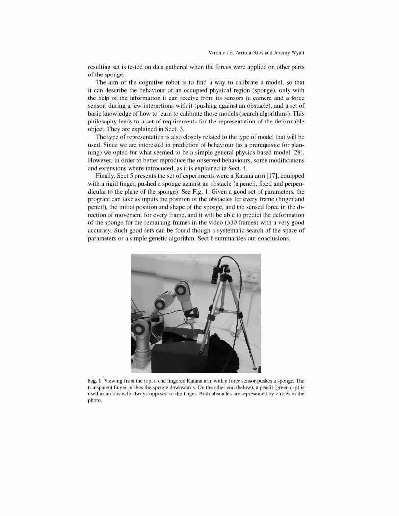
Finally, Sect 5 presents the set of experiments were a Katana arm [17], equippedwith a rigid finger, pushed a sponge against an obstacle (a pencil, fixed and perpen-dicular to the plane of the sponge). See Fig. 1. Given a good set of parameters, theprogram can take as inputs the position of the obstacles for every frame (finger andpencil), the initial position and shape of the sponge, and the sensed force in the di-rection of movement for every frame, and it will be able to predict the deformationof the sponge for the remaining frames in the video (330 frames) with a very goodaccuracy. Such good sets can be found though a systematic search of the space ofparameters or a simple genetic algorithm. Sect 6 summarises our conclusions.
Fig. 1 Viewing from the top, a one fingered Katana arm with a force sensor pushes a sponge. Thetransparent finger pushes the sponge downwards. On the other end (below), a pencil (green cap) isused as an obstacle always opposed to the finger. Both obstacles are represented by circles in thephoto.

2D Mass-spring-like Model for Prediction
2 Related Work
Modelling the behaviour of a real deformable object comprises several aspects:
Perception: The robot must receive information about the current configuration ofthe real object. Some form of internal representation must be created [21, 18].
Tracking: The robot must follow the deformation of the object as a continual pro-cess affecting the same entity [9, 10]. Furthermore, since we are interested inprediction, works from the literature that cover predictive tracking [30] 1 are ofinterest. There is also a very good, but also very complex, work by Luo and Nel-son [11] where visual tracking can provide haptic information, after a calibrationphase.
Simulation: Models of deformable objects are used in medicine [14] (mainly forsurgery training, where highly accurate and fast haptic simulations are required,or automatised diagnosis, where the main interest is in identification and/or track-ing [27, 16]) and computer graphics [20, 19] (where it is enough to get a visuallyplausible, even though not accurate, simulation).
Manipulation: Uncertain or qualitative models that only focus on relevant points[8, 25, 12] can be used for particular cases of robotic manipulation. There isplenty of literature in industrial robotics whose main aim is manipulation [23,22] (there is an extensive review by Saadat and Nan [24]). Even though mostapproaches tend to be quite restrictive to a particular application.
2.1 Physics Based Models
Two families of physics based models pervade the scientific literature for de-formable objects [4]:
Finite Element Methods (FEM): Objects are divided into unitary surface or vol-umetric elements joined at discrete node points where a continuous equilibriumequation is approximated over each element. To solve the system, large matricesconnecting the elements must be solved, consuming a great amount of time andresources.
Mass-spring Methods: Objects are represented by meshes where masses are lo-cated at the nodes and the edges correspond to springs connecting them. It ispossible to discretise and integrate the system of equations for each mass pointseparately, making the process easy and parallelisable.
Apart from them, other approaches include: Long Elements Method, Non-linearFEM, Geometric Nonlinear FEM and Boundary Element Method [1].
1 This is: that the program predicts the new configuration of the object before the new frame ofinformation is acquired, then compares and may correct.
Veronica E. Arriola-Rios and Jeremy Wyatt
2.1.1 Finite Element Methods
In the area of predictive tracking, the work by Malassiotis [13] resembles the struc-ture of our approach (even though the underlying model is different): a triangularmesh is calculated to cover the 2-D image of a textured deformable object of in-terest. The aim of his technique is to identify the principal deformation modes inthe mesh over the observed object, so that future deformations can be expressed ascombinations of these modes. The 2-D shape of the object is modelled with an elas-tic membrane deformed by virtual forces, its strain energy is calculated by makinguse of the finite element theory, which causes it to be costly in time and complexity.This information will guide the deformations of the mesh, while trying to predicthow the object will be deformed.
2.1.2 Mass-spring Methods
Among the most innovative works are: Burion et al. [3], who use a mass-springskeleton model [4], where filling spheres are placed along the medial skeleton ofthe object and are connected together with elastic links, which model elongation,flexion and torsion properties. They use a particle filter algorithm to estimate thestiffness coefficients.
Nevertheless, we chose to work with Teschner’s model [28], following the ex-perience of Morris [15]. Here, additionally to the traditional damped springs at theedges, two new energy terms are devised to enforce preservation of area and volume,making this model more adequate to simulate a broad range of realistic behaviours.Also, the terms for distance, area and volume preservation have the same structure,this makes the model uniform and straightforward to implement and extend.
2.2 Computer Graphics
The first aim of Computer Graphics is to provide with rich, general and flexiblerepresentation of deformable objects: meshes and splines cover these requirementsin different ways [26]. A good review of the techniques used up to 1997 for Com-puter Graphics, including FEM and mass-spring methods for dynamic simulationsis in [6]. There is a lot of work in the area of Computer Graphics, specially in themodelling of clothes [5].
3 Representation of the Deformable Object
It is clear that it took centuries for humans to discover the molecular and atomicstructure of matter, some time more to understand its interactions, how to control the
2D Mass-spring-like Model for Prediction
creation of particular structures, and how the macroscopic attributes emerge fromthe underlying microscopic composition of the material [7]. Nevertheless, there wasan intelligent process that allowed humans to handle materials even before they hadthis knowledge [29]. Since in this work we are interested in the programming ofcognitive robots, the model to be used does not have to be physically correct, but itsbehaviour must correspond with the observations, and it must be possible to applyit easily to a wide range of materials and shapes.
3.1 Requirements
There is a set of simple requirements, given by the predictive task we have in mind:
1. The representation must be deformable, just as the original material.2. Given that we are receiving visual information in 2D, we will try to keep things
simple by having an internal representation also in 2D.3. It must be possible to represent interactions between solids (rigid and deformable).
Particularly, we need to detect contact.4. The model must provide information beyond the points where data was collected
[interpolation and extrapolation] e.g. beyond the points where testing forces wereapplied and deformations or displacements were registered. Observe that, in par-ticular, the force sensor in our experiment only provides readings in one point,but the shape of the robotic finger is actually a sphere. Also, the initial shape andposition of the mesh is given for the first frame, but the model must be able todeform the initial representation accordingly.
3.2 Mass-spring Mesh
A very common representation of any object in computer graphics is a mesh. A meshcan be easily rendered, transformed (translated, rotated, resized, etc.) and deformed.It is also quite common to use meshes for physics based methods. Each node hasa mass, and neighbour nodes are connected by edges. Since we are interested inreal time modelling of dynamic behaviour, the evaluation of a mass-spring model isappealing, therefore, the mesh must be designed taking this into account. For mass-spring models, the shape of the mesh can lead to undesired anisotropic behaviours,since forces are applied only through the edges (which become springs) [2]. Toattend this, to a certain extent, we opted for taking the simple approach of generatinga symmetric triangular mesh.

Veronica E. Arriola-Rios and Jeremy Wyatt
4 Physics Model
4.1 Antecedents
This research approach is inspired by the work by Morris[15]. He works with a 3Dfinite element model as a ground truth to automatically calibrate an almost equiv-alent instance of the mass-spring model proposed by Teschner [28], which can beused instead for real time simulations. Random sets of parameters are proposed andevaluated at equilibrium positions, an adaptive simulated annealing search is usedto modify the best parameters of the springs and look for better candidates. Ob-serve that only the final equilibrium positions are evaluated, the forces are appliedon vertices of the mesh and the position of the objects is fixed.
4.2 Inputs
The katana arm has been equipped with a 6 degrees sensor (forces and torques),but for the experiments in this research only one direction is relevant. A colourcamera is placed perpendicular to the direction of movement so that it can capturethe movement of the finger and the deformation of the sponge. See Fig. 2.
Fig. 2 Viewing from the top, a one fingered Katana arm with a force sensor pushes a sponge. Thetransparent finger pushes the sponge downwards. On the other end (below), a pencil (green cap) isused as an obstacle always opposed to the finger. Both obstacles are represented by circles in thephoto.

2D Mass-spring-like Model for Prediction
4.3 Graphical Constraints
Given that the main focus of this work is on the deformable object, the treatmentof the rigid objects involved has been simplified as much as possible. Both, thefinger and the pencil are represented as instances of hard circular obstacles. Thisimplies that any element of the deformable mesh will not be allowed to enter orcross over the enclosed region. This constraint is enforced at every frame duringthe simulation through a standard set of collision detection subroutines. Also thetriangulation must remain without crossings. Whenever the displacemente of a nodeproduces a crossing, the opposite ending of the affected triangle and the node itselfget pushed in opposite directions to undo the error. If a set of parameters can notrespect this constraints it is eliminated.
4.4 Energy→ Force terms
The core of the model is in the energy terms that enforce the preservation of threequantities: length of the springs, area of each triangle and the internal angles ofthe triangles. The first two terms are directly derived for the two dimensional casefollowing Teschner’s method [28]. The last term is our original contribution.
Equal masses are allocated at the nodes of the mesh and the edges correspond tothe springs. The dynamics of the deformation of the objects are represented throughdynamic constraints from which potential energies are obtained. The dynamics ofthe system are ruled by the forces that minimise these energies. Teschner indicateshow to derive those forces and Morris [15] uses geometrical arguments to explainthem. The following table indicates the corresponding expressions.
Preservation of Distance:
The spring will tend to recover its original length. Strictly this is the only term thatwill force the triangles to recover their original shape. See Fig. 3.a.
Energy:
ED(pi, p j) =12
kD
(|p j− pi|−D0
D0
)2
(1)
Force:
FD(pi) = kD (|p j− pi|−D0)(
p j− pi
|p j− pi|
)(2)
Where pi, p j are the mass point positions, kD the stiffness coefficient, ED thepotential energy based on the difference between the current distance of two pointsand the initial or rest distance D0, with D0 6= 0. FD is the force resulting from thisenergy and it will pull or push the masses in the direction of the line that joins them.

Veronica E. Arriola-Rios and Jeremy Wyatt
Preservation of Surface Area:
Every triangle in the mesh tries to recover its area. This term does not respect theoriginal shape of the triangle, thus allowing the hole mesh to find a new equilibriumeven if greatly deformed. See Fig. 3.b.
Energy:
EA(pi, p j, pk) =12
kA
(12 |(p j− pi)× (pk− pi)|−A0
A0
)2
(3)
Force:
FA(pi) = kA · f orcemagA(pi) · f orcedirA(pi) (4)
f orcemagA(pi) =12 ((pk− pi)× (p j− pi))−A0
A0
f orcedirA(pi) =FA(pi)|FA(pi)|
=areagradient(pi)|areagradient(pi)|
areagradient(pi) = (pi− p j)−(
(pk− p j) ·(pk− p j) · (pi− p j)(pk− p j) · (pk− p j)
)Where the energy EA considers triples of mass points that build surface triangles.
EA represents energy based on the difference of the current area of a surface triangleand its initial area A0 with A0 6= 0. Here kA is an area stiffness coefficient. Eachmass with move in the direction of the height of the triangle that passes through it,to increase or decrease its area.
Fig. 3 a. The linear force of the spring pulls inside if the spring was elongated, or outside if itwas compressed. b. The triangle tries to quickly recover its area by pulling all its vertices along itscorresponding heights.

2D Mass-spring-like Model for Prediction
Preservation of Angles:
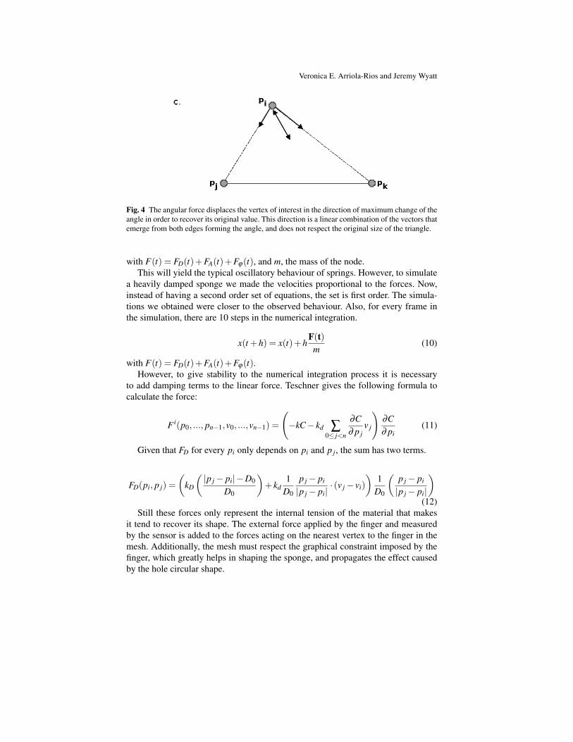
We added an extra term to enforce the preservation of angles. The energy dependson the difference of the angles between adjacent edges. The force emerging fromthis term is harder to visualize, it is a linear combinations of the vectors along theedges that form the angle of interest, it pretends to restore the original angle, butdoes not pay attention to the original size. See Fig. 4. Therefore, it helps recover asimilar triangle, but if used alone can collapse or explode the triangle. An additionalline in the code also forces an inverted angle to recover its original orientation.
Energy:
Eϕ(ϕ) =12
kϕ(ϕ−ϕ0) * (5)
ϕ(pi, p j, pk) = arccos
((p j− pi) · (pk− pi)∥∥p j− pi
∥∥‖pk− pi‖
)2
* It was also considered to multiply Eϕ by the lengths of the edges, but it hasn’timproved the performance of the model.
Where ϕ is the angle between adjacent edges, Eϕ is the energy associated tochanges in the angle and kϕ , the corresponding stiffness constant. Contrary to theprevious cases, it is not so evident in which direction the force will act.
Force:
Fϕ(pi) = kϕ(ϕ−ϕ0)∂ϕ
∂ pi(6)
∂ϕ
∂ pi(pi) =
1
d jidki
√1−[
pp(d ji)(dki)
]2
{[1− pp
d2ki
](pk− pi)+
[1− pp
d2ji
](p j− pi)
}
pp(pi) = (p j− pi) · (pk− pi)d ji(pi) =
∥∥p j− pi∥∥
dki(pi) = ‖pk− pi‖ (7)
The differential equations that rule the behaviour of the system are integratedwith a numerical approach. Originally the acceleration of the masses is proportionalto the force, the equation must be integrated twice to obtain the positions as a func-tion of time. In this case, in order to compute the new state of the system (x(t + h)position at time t + h, v(t + h) velocity at time t + h) the Verlet integration schemeis used [5].
x(t +h) = 2x(t)− x(t−h)+h2 F(t)m
+O(h4) (8)
v(t +h) =x(t +h)− x(t−h)
2h+O(h2) (9)
Veronica E. Arriola-Rios and Jeremy Wyatt
Fig. 4 The angular force displaces the vertex of interest in the direction of maximum change of theangle in order to recover its original value. This direction is a linear combination of the vectors thatemerge from both edges forming the angle, and does not respect the original size of the triangle.
with F(t) = FD(t)+FA(t)+Fϕ(t), and m, the mass of the node.This will yield the typical oscillatory behaviour of springs. However, to simulate
a heavily damped sponge we made the velocities proportional to the forces. Now,instead of having a second order set of equations, the set is first order. The simula-tions we obtained were closer to the observed behaviour. Also, for every frame inthe simulation, there are 10 steps in the numerical integration.
x(t +h) = x(t)+hF(t)m
(10)
with F(t) = FD(t)+FA(t)+Fϕ(t).However, to give stability to the numerical integration process it is necessary
to add damping terms to the linear force. Teschner gives the following formula tocalculate the force:
F i(p0, ..., pn−1,v0, ...,vn−1) =
(−kC− kd ∑
0≤ j<n
∂C∂ p j
v j
)∂C∂ pi
(11)
Given that FD for every pi only depends on pi and p j, the sum has two terms.
FD(pi, p j) =(
kD
(|p j− pi|−D0
D0
)+ kd
1D0
p j− pi
|p j− pi|· (v j− vi)
)1
D0
(p j− pi
|p j− pi|
)(12)
Still these forces only represent the internal tension of the material that makesit tend to recover its shape. The external force applied by the finger and measuredby the sensor is added to the forces acting on the nearest vertex to the finger in themesh. Additionally, the mesh must respect the graphical constraint imposed by thefinger, which greatly helps in shaping the sponge, and propagates the effect causedby the hole circular shape.

2D Mass-spring-like Model for Prediction
4.5 Implementation
The algorithms where implemented in C++, making use of the GNU compiler gcc4.4.4. The triangulations where managed with the CGAL library, and the vision partwas handled with OpenCV.
4.6 Weaknesses
At the beginning we assumed that the spring terms would suffice even to reproducethe slight translation of the sponge as it is pushed by the finger, since pushing aspring should make this push its neighbours and so on. However, our first experi-ments showed it not to be the case. The effect of pushing a spring get diluted amongthe deformation of the spring and the area and angular terms. In order to obtain thetranslation, we must add a solid propagation of the finger’s force. This is, that part ofthe force is absorbed in deformation, while another amount affects all vertices andproduces an even displacement. For the moment we just added an extra parameterto the model that fixes the amount of force that is invested in translation.
Also the discretisation of the equations of movement produce jumps whose ef-fects are hard to control. Sometimes the constrains can not be met. In order to con-sider new behaviours (plasticity, rotations, etc.) it is necessary to add new terms tothe model and the search space is increased. This shows how different behaviourrequire different physical models, which leaves open the question of whether thereis a simpler mechanism that can cover many behaviours on the same basis.
5 Experiments
5.1 Evaluation: Difference of Areas
The function used to automate the decision of what makes a good set of parametersis quite simple, but provides a sufficient criterion to eliminate bad sets of parameters.It consists in measuring the difference between the area occupied by the image ofthe sponge and the area covered by the mesh of the model (this is done pixel bypixel). The bigger this difference, the worst the model. All the differences frame byframe are added up to assign a mark to the set of parameters during the hole durationof the video. See Fig. 5.

Veronica E. Arriola-Rios and Jeremy Wyatt
Fig. 5 a) Shows the original image with the mesh overlaid as the simulation is executed. b) Thearea occupied by the sponge. c) The area occupied by the mesh. The evaluation function countsthe pixels in the difference: those in the sponge that are not in the mesh, and those in the mesh thatare not in the sponge. The positions are absolute.
5.2 Results
With the genetic algorithm, after 7 generations the set of parameters with the bestmark has been the same. It produced the videos summarized in Fig. 6.
Fig. 6 Sequence taken from a simulation with the best set as evaluated by a genetic algorithm. a)Over the video used for evaluation of the parameters. a) 5. In the last frame an error remains doto the oversimplification of the translation function: the elements of the sponge keep being pusheddown even after the finger has stopped moving (frame 300). b) Same model and parameters butwith the forces acting on different positions. The predictions are fairly correct for 250 frames.

2D Mass-spring-like Model for Prediction
From running the systematic search for parameters we noticed that big valuesfor the preservation of areas create severe problems while trying to maintain thegraphical constraints. Because of this, most of the sets of parameters get discarded.The best results are characterized by a high value of kD and about the half of it for kϕ .There are also differences in magnitude depending on the number of elements in themesh. If there are more elements, the stiffness coefficients are smaller. Unfortunatelythis kind of search can take up to several weeks in a PC with an Intel(R) Core(TM)2Quad CPU Q6600 @ 2.40GHz.
6 Conclusions
We managed to automatically calibrate a mass-spring-like model taking images andforces from a real sponge as ground truth. The calibrated model shows severe limi-tations in the exactitude of the predictions after 250 frames (2500 integration steps).Furthermore, different terms must be added beforehand so that the program canconsider different types of movements. This shows that, if we want to program acognitive robot using physical models, it would be required to provide the robotwith a big collection of components to consider. It is not clear, if even this wouldsuffice to deal with the variety of materials in the everyday world.
Acknowledgements Thank you to Dr. Helge Ritter and Matthias Schoepfer from the University ofBielefeld, Germany for their suggestions leading to the completion of this work. To the CONACYTin Mexico and to the ORSAS scheme in the UK for sponsoring my PhD.
References
1. R. Balaniuk and K. Salisbury. Dynamic simulation of deformable objects using the longelements method. 10th Symposium On Haptic Interfaces For Virtual Environment And Tele-operator Systems, Proceedings, pages 58–65, 2002.
2. David Bourguignon and Marie-Paule Cani. Controlling anisotropy in mass-spring systems. InNadia Magnenat-Thalmann, Daniel Thalmann, and Bruno Arnaldi, editors, 11th Eurograph-ics Workshop on Computer Animation and Simulation, EGCAS 2000, August, 2000, SpringerComputer Science, pages 113–123, Interlaken, Suisse, 2000. Springer-Verlag.
3. S. Burion, F. Conti, A. Petrovskaya, C. Baur, and O. Khatib. Identifying physical properties ofdeformable objects by using particle filters. 2008 Ieee International Conference On RoboticsAnd Automation, Vols 1-9, pages 1112–1117, 2008.
4. F. Conti, O. Khatib, and C. Baur. Interactive rendering of deformable objects based on a fillingsphere modeling approach. In Robotics and Automation, 2003. Proceedings. ICRA ’03. IEEEInternational Conference on, volume 3, pages 3716 – 3721, sept. 2003.
5. Arnulph Fuhrmann, Clemens Gro, and Volker Luckas. Interactive animation of cloth includingself collision detection. Journal of WSCG, 11(1):141–148, February 2003.
6. Sarah F. F. Gibson and Brian Mirtich. A survey of deformable modeling in computer graphics.Technical report, MERL (Mitsubishi Electric Research Laboratory), 1997.
7. Wenceslao Gonzlez-Vias and Hctor L. Mancini. An Introduction To Materials Science. Prince-ton University Press, U.S.A., 2004. Translation of: Ciencia de los Materiales.

Veronica E. Arriola-Rios and Jeremy Wyatt
8. S. Hirai and T. Wada. Indirect simultaneous positioning of deformable objects with multi-pinching fingers based on an uncertain model. Robotica, 18:3–11, 2000.
9. Michael Kass, Andrew Witkin, and Demetri. Terzopuolos. Snakes: Active contour models.International Journal Of Computer Vision, 1(4):321–331, 1988.
10. S. Krinidis and L. Pitas. Fast free-vibration modal analysis of 2-d physics-based deformableobjects. Ieee Transactions On Image Processing, 14(3):281–293, 2005.
11. Y. H. Luo and B. J. Nelson. Fusing force and vision feedback for manipulating deformableobjects. Journal Of Robotic Systems, 18(3):103–117, 2001.
12. Jeremy Maitin-Shepard, Marco Cusumano-Towner, Jinna Lei, and Pieter Abbeel. Cloth grasppoint detection based on multiple-view geometric cues with application to robotic towel fold-ing. In International Conference on Robotics and Automation (ICRA), 2010.
13. S. Malassiotis and M. G. Strintzis. Tracking textured deformable objects using a finite-elementmesh. Ieee Transactions On Circuits And Systems For Video Technology, 8(6):756–774, 1998.
14. Tim. McInerney and Demetri. Terzopoulos. Deformable models in medical image analysis: asurvey. Med Image Anal, 1(2):91–108, 1996.
15. D. Morris and K. Salisbury. Automatic preparation, calibration, and simulation of deformableobjects. Computer Methods In Biomechanics And Biomedical Engineering, 11(3):263–279,2008.
16. S. D. Mowbray and M. S. Nixon. Automatic gait recognition via fourier descriptors of de-formable objects. Audio-And Video-Based Biometric Person Authentication, Proceedings,2688:566–573, 2003.
17. Neuronics. Katana user manual and technical description. http://www.neuronics.ch, 2004.18. Richard A. Newcombe and Andrew J. Davison. Live dense reconstruction with a single mov-
ing camera. In CVPR, 2010.19. James F. O’Brien, Adam W. Bargteil, and Jessica K. Hodgins. Graphical modeling and ani-
mation of ductile fracture. ACM Trans. Graph., 21(3):291–294, 2002.20. James F. O’Brien and Jessica K. Hodgins. Graphical modeling and animation of brittle frac-
ture. In Proceedings of ACM SIGGRAPH 1999, pages 137–146. ACM Press/Addison-WesleyPublishing Co., August 1999.
21. Saiprasad Ravishankar, Arpit Jain, and Anurag Mittal. Multi-stage contour based detection ofdeformable objects. Computer Vision - Eccv 2008, Pt I, Proceedings, 5302:483–496, 2008.
22. A.. Remde, F. Abegg, and H. Worn. Ein allgemainer ansatz zur montage deformierarbarerlinearer objekte mit industrierobotern (a general approach for the assembly of deformablelinear objects with industrial robots). In Robotik’2000, Berlin, Germany, June 2000.
23. A. Remde, E. Pfaffenberger, and H. Worn. Manipulating deformable linear objects - force-based detection of contact state transitions. 2000 Ieee/Rsj International Conference On Intel-ligent Robots And Systems (Iros 2000), Vols 1-3, Proceedings, pages 1480–1486, 2000.
24. M. Saadat and P. Nan. Industrial applications of automatic manipulation of flexible materials.Industrial Robot, 29(5):434–442, 2002.
25. Mitul Saha and Pekka Isto. Manipulation planning for deformable linear objects. Ieee Trans-actions On Robotics, 23(6):1141–1150, 2007.
26. Y. Song and L. Bai. 3d modeling for deformable objects. Articulated Motion And DeformableObjects, Proceedings, 5098:175–187, 2008.
27. W. Sun, M. Cetin, R. Chan, and A. S. Willsky. Learning the dynamics and time-recursive boundary detection of deformable objects. Ieee Transactions On Image Processing,17(11):2186–2200, 2008.
28. Matthias Teschner, Bruno Heidelberg, Matthias Muller, and Markus Gross. A versatile and ro-bust model for geometrically complex deformable solids. In Proceedings of Computer Graph-ics International (CGI’04), pages 312–319, Crete, Greece, June 16-19 2004.
29. Lyn Wadley, Tamaryn Hodgskissb, and Michael Grantb. Implications for complex cognitionfrom the hafting of tools with compound adhesives in the middle stone age, south africa. Pro-ceeding of the National Academy of Sciences of the United States of America, 106(24):9590–9594, June 2009.
30. L. Q. Xu and D. C. Hogg. Using neural network to learn spatial-temporal models for movingdeformable objects tracking. International Workshop On Neural Networks For Identification,Control, Robotics, And Signal/Image Processing - Proceedings, pages 145–153, 1996.