2756 ieee sensors journal, vol. 12, no. 9, september 2012...
TRANSCRIPT

2756 IEEE SENSORS JOURNAL, VOL. 12, NO. 9, SEPTEMBER 2012
Design and Development of a Novel PassiveWireless Ultrasensitive RF Temperature
Transducer for Remote SensingTrang T. Thai, Jatlaoui M. Mehdi, Franck Chebila, Hervé Aubert, Senior Member, IEEE,
Patrick Pons, Gerald R. DeJean, Manos M. Tentzeris, Fellow, IEEE, and Robert Plana
Abstract— A wireless, passive, and ultrasensitive temperaturetransducer is presented in this paper. The transducer consistsof split ring resonators loaded with micro-bimorph cantilevers,which can potentially operate up to millimeter-wave frequencies(above 30 GHz). As the temperature changes, the bimorphcantilevers deflect and result in a shift of the resonant frequencyof the split rings. A design is proposed, that has a maximumsensitivity of 2.62 GHz/µm, in terms of frequency shift perdeflection unit, corresponding to a sensitivity of 498 MHz/°Cfor an operating frequency around 30 GHz, i.e. a frequencyshift of 1.6% per °C. Theoretically, it’s about two orders ofmagnitude higher than the existing sensors observed in the sameclass. This sensor design also offers a high Q factor and is ultra-compact, enabling easy fabrication and integration in micro-electromechanical systems technology. Depending on the choiceof materials, the proposed designs can also be utilized in harshenvironments. As a proof of concept, a prototype is implementedaround 4.7 GHz which exhibits a frequency shift of 0.05%/°C,i.e. 17 times more sensitive than the existing sensors.
Index Terms— Micro-electromechanical systems (MEMS)cantilevers, passive remote sensing, radar cross section (RCS),radio frequency transducer, split ring resonators (SRRs), tem-perature sensor, wireless sensor.
I. INTRODUCTION
PASSIVE sensors are critical and highly desirable inremote sensing platforms, where long term environment
controlling and monitoring can take place. In addition,temperature sensing is critical for use in automotive, medical,and industrial applications. More specific applications includemonitoring systems for engine operations, space shuttles,
Manuscript received January 4, 2012; revised April 6, 2012; accepted May3, 2012. Date of publication May 30, 2012; date of current version July 24,2012. The associate editor coordinating the review of this paper and approvingit for publication was Prof. Istvan Barsony.
T. T. Thai is with the Georgia Institute of Technology, Atlanta, GA 30318USA, with CNRS-LAAS, Toulouse 31077, France, and also with MicrosoftResearch, Redmond, WA 98052-6399 USA (e-mail: [email protected]).
J. M. Mehdi is with AS+/IPDiA, CNRS-LAAS, Toulouse 31077, France(e-mail: [email protected]).
F. Chebila is with CNRS-LAAS, Toulouse 31077, France (e-mail:[email protected]).
H. Aubert, P. Pons, and R. Plana are with the University ofToulouse, UPS, INSA, INP, ISAE, LAAS, Toulouse 31077, France (e-mail:[email protected]; [email protected]; [email protected]).
G. R. DeJean is with Microsoft Research, Redmond, WA 98052-6399 USA(e-mail: [email protected]).
M. M. Tentzeris is with the Georgia Institute of Technology, Atlanta,GA 30318 USA (e-mail: [email protected]).
Color versions of one or more of the figures in this paper are availableonline at http://ieeexplore.ieee.org.
Digital Object Identifier 10.1109/JSEN.2012.2201463
aircraft in-flight conditions, and road and bridge maintenance.Therefore, it is highly desirable for the sensors to be wireless,battery-less, compact, and easily integrated with other wirelesspassive sensors because multi-physical sensing is requiredfor complete environmental monitoring. A wireless, passivetemperature transducer is a device without internal powerplaced at the monitored site that can transform the localtemperature into an output signal that can be read wirelesslyby a control system located remotely from the monitored site.Some techniques for temperature measurements include thosebased on thermoelectricity, temperature dependent variationof the resistance of electrical conductors, fluorescence,and spectral characteristics [1]. However, most existingtemperature sensors require a power source, and those withhigh sensitivity suffer from performance degradation above130 °C [2]–[4]. Recently, a new class of passive, wirelesssensors was introduced based on the correspondence betweenthe physical parameters and shifts in resonant frequencies ofa resonating structure [5]–[7]. A capacitively-loaded MEMS(micro-electromechanical systems) slot element for wirelesstemperature sensing of up to 300 °C was introduced [5] buthad a low sensitivity of about 580 kHz/°C around 19.4 GHz,i.e. 0.003% of frequency shift per °C.
A new wireless, passive, and ultrasensitive temperaturetransducer operating at radio frequencies (RF) is proposedin this paper. The transducer consists of split ring res-onators (SRRs) integrated with bi-layer micro-cantilevers. Thebimorph cantilevers consist of layers of different thermalexpansion coefficients that cause them to bend as temper-ature changes [6]. Utilizing MEMS allows devices to havelow costs, small form factors, and ease of fabrication andintegration. The SRRs can potentially operate up to millimeter-wave frequencies above 30 GHz. The micro-cantilevers areplaced over split gaps of the SRRs. As the cantilevers deflectin response to temperature changes, the resonant frequen-cies of the SRR are shifted. The bimorph material choicescan be varied and adapted for various temperature rangesdesired for different applications while requiring little designmodification; thus, it may allow sensing applications up to300 °C or higher. Without loss of generality, a prototypescaled up in size with operating frequency of 4.7 GHz ispresented in this paper to demonstrate the proof-of-concept.In a sensing system, sensor nodes should not only provideinformation about the physical conditions of the surround-ing environment, but also allow their unique identifications
1530–437X/$31.00 © 2012 IEEE

THAI et al.: NOVEL PASSIVE WIRELESS ULTRASENSITIVE RF TEMPERATURE TRANSDUCER 2757
Fig. 1. Topology of the SRRs and bimorph cantilevers.
in practical networks of multiple sensor nodes. Therefore,based on the approach recently reported in [8] and [9],the authors also propose a newly improved micro-sensor iden-tification technique that allows for an efficient communicationbetween a network of many passive sensor nodes and acentral monitoring station. The communication is based onthe reading/monitoring of the radar cross section (RCS) levelof loaded multi-band scatterers by a frequency-modulated-continuous-wave (FMCW) radar. The RCS measurements ofthe temperature prototype are performed to illustrate a pos-sible implementation of the transducer in passive, wirelesssensing nodes for remote sensing networks. The conceptpresented in this paper was first introduced in our previouspublication [10]. In this extended work, the millimeter-wavedesigns have been optimized to achieve higher sensitivities,which is included in Sect. II. Additionally, the operationalprinciples of the transducer with an equivalent circuit modelare discussed in Sect. III. Direct temperature measurementsof the low frequency, proof-of-concept prototype are shownin Sect. IV to address the linear response limits of the sensor.An example implementation of the transducer based on radarcross section measurements is presented in Sect. V, followedby the conclusions in Sect. VI.
II. DESIGNS AND SIMULATIONS
A. Designs
The transducer consists of double split rings positioned ona dielectric substrate. The slits of the rings are covered withbimorph micro-cantilevers whose layers are made from twodifferent materials, gold with thermal coefficient of 14.1 (10−6
K−1) and silicon with thermal coefficient between 4.7 – 7.6(10−6 K−1) [11]. The design of the SRRs integrated withcantilevers is shown in Fig. 1. The dimensions of the splitrings are as follows: rint = 230 μm, c = 120 μm, d = 50 μm,and s = 45 μm. The substrate is made of glass with dielectricconstant εr = 4.82 and a thickness of 150 μm. The cantilevershave a length, Lcant, of 180 μm, the anchors have a lengthof 50 μm, and dcap is a variable parameter that symbolizesthe air gap between the cantilever tip and the ring surface,which is the same as the anchor’s thickness in simulations.Both thicknesses of the Au and Si layers are 0.5 μm.
The SRRs of the sensor can be excited by two distinctmethods. In the first method, a plane wave is incident onthe face of the SRRs as illustrated in Fig. 2. It shouldbe noted that an incident electromagnetic (EM) wave mustexcite the magnetic resonance of the SRR through magneticcoupling in which the external magnetic field (H-field) should
Fig. 2. Setup of the first approach to excite the SRRs.
Fig. 3. Setup of the second approach to excite the SRRs with (a) 3-Dview and (b) top view of the circuit with substrate not shown and dimensionsindicated in micrometers.
be polarized perpendicular to the SRR plane, i.e. the directionof propagation should be parallel to the SRR. However, if thedirection of propagation is normal to the SRR plane and theincident electric field (E-field) is parallel to an imaginary linecrossing the slits (Fig. 2), the E-field coupling can induce themagnetic resonance of the SRR [12]. In the second approach,a coplanar waveguide (CPW) is placed on the other side ofthe substrate, and the slits of the SRR, denoted by s, arealigned to a gap between the signal line and the ground plane,as illustrated in Fig. 3. Thus, the SRRs can be excited bythe fringing field that travels along the CPW, which has animpedance of 50 �.
B. Radio Frequency Simulations
Since the electromagnetic (EM) fields of the cantilevers aremostly concentrated in the air region sandwiched betweenthe cantilevers and the metal rings, the deflection of themicro-cantilevers is approximated with a uniform deflectionacross the whole length of the cantilevers in simulations andmeasurements. The relationship between the deflection of thecantilever tip and temperature is shown in Eq. (1) (see [11]for details), where δ denotes the deflection, α1 and α2 denotethermal expansion coefficients of the two layers, t1 and t2denote the thicknesses of the two layers, and �T denotesthe temperature change. From Eq. (1), the design of thecantilevers presented in Fig. 1 is estimated to have a sensitivityof 0.19 μm/°C.
δ = �T (α1 − α2)(1 + t1/t2)Lcant2
2(t1 + t2)(1)
The simulation results of the first excitation approach, aspresented in Fig. 2, are shown in Fig. 4. In this model, only onecantilever is implemented per SRR, which is positioned overthe split of the inner rings. The two resonance modes observed

2758 IEEE SENSORS JOURNAL, VOL. 12, NO. 9, SEPTEMBER 2012
Fig. 4. Magnitude of transmission coefficient S21 of the sensor in the firstexcitation configuration shown in Fig. 2.
in this frequency range (between 20–40 GHz) are excited bythe two rings in this structure. Observed from Fig. 4, thehighest sensitivity is shown to be 1.41 GHz/μm, correspondingto 268 MHz/°C using Au-Si bimorph cantilevers.
The simulation results of the second excitation approach,as presented in Fig. 3, are shown in Fig. 5. In this model,two cantilevers are implemented per SRR, one is positionedover the inner ring split, and the other is placed over the outerring split. The resonances in Fig. 4 are different from thoseobserved in Fig. 3 because the effective impedance in thisstructure is different from that presented in Fig. 2. From Fig. 5,the sensitivity is recorded as 2.62 GHz/μm, correspondingto 498 MHz/°C, i.e. 1.6% frequency shift per °C, more thantwo order of magnitude higher than the sensitivity reported in[5] where a slot resonator operating between 19.3–19.5 GHzwas introduced with bimorph micro-cantilevers yielding asensitivity of about 580 kHz/°C or 0.003% frequency shiftper °C. In the slot design in [5], the cantilevers deflect from200 μm to a flat position, corresponding to a temperature rangeof 25–300 °C.
III. PRINCIPLES OF OPERATION
The temperature sensing mechanism of the transducer isbased on two uncoupled principles: 1) deflections of bimorphcantilevers in response to temperature changes and 2) resonantfrequency shifts in response to deflections of cantilevers. Sincethey are two independent physical phenomena, they can beoptimized separately.
A. Mechanical Response – the Deflection of the Cantilevers inResponse to Temperature Change
The deflection is caused by the difference in thermalexpansion coefficients of the two materials that constitutethe two different layers of the cantilevers. This mechanismis well-known and has been utilized widely in numerousapplications [11], [13]. As temperature changes the length ofeach cantilever layer expands at different rates. Since the twolayers are bonded together, the cantilevers are bent in orderto accommodate the different rates of change in the lengthof their layers. The deflection can be estimated utilizing (1)presented in Section II. The bimorph cantilevers can realize
Fig. 5. Magnitude of transmission coefficient S21 of the sensor in the secondexcitation configuration shown in Fig. 3.
various operating ranges depending on the material choicesgiven that they provide the linear mechanical deflection withinthe temperature range of interest. Despite extended thermalcycling, the bimorph cantilevers are robust, and they reliablyreturn to the same position at a given temperature as longas they are operated within the range limits for a particularmaterial choice [11]. In the fabrication of bimorph micro-cantilevers, the tips of the cantilevers are usually deflected,referred to as initial deflection, which is due to the stress andstrain during different MEMS processes. The initial deflectionis in equilibrium at room temperature; then, it changes inresponse to temperature changes. As a result, this initialdeflection determines the resonances of the sensor at roomtemperature, which can be controlled to an acceptable toler-ance. The discussion of this tolerance limit is not within thescope of this paper.
B. Electromagnetic Response – Resonant Frequency Shifts inResponse to the Deflections of the Cantilevers
The split ring structure was first proposed in [14] and hasattracted growing interest since. Many variations of SRRshave been proposed to realize materials with negative valuesof magnetic permeability, also known as metamaterials. Themetamaterials, based on SRRs, are highly frequency selectivesuggesting that the SRR elements have a very high qualityfactor (Q > 600) [15], [16]. When the SRRs are excited, anelectromotive force is induced around the rings. However, dueto the slits on each ring, displacement currents flow from onering to another across the slot between them; thus, the SRRseffectively inherit a distributed capacitance. As a result, thefield at the slit on each ring has high intensity, which suggeststhat for any modification of the capacitance of these slots, thecurrents on the rings can be influenced significantly. Therefore,such change in the currents may induce a significant shift inthe resonant frequencies. In the design proposed in Fig. 1,the metal layer (gold) of the cantilever constitutes the lowerlayer of the bimorph cantilever, which is supported by a goldanchor that shorts the bimorph cantilever to one end of thesplit ring. The free end of the bimorph cantilever effectivelyforms a parallel plate capacitance with the other end of thesplit ring, making the split gap capacitance sensitive to thedeflection of the bimorph cantilever. Note that the split gap
THAI et al.: NOVEL PASSIVE WIRELESS ULTRASENSITIVE RF TEMPERATURE TRANSDUCER 2759
Lav
Ceq
R
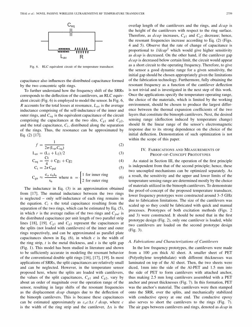
Fig. 6. RLC equivalent circuit of the temperature transducer.
capacitance also influences the distributed capacitance formedby the two concentric split rings.
To further understand how the frequency shift of the SRRscorresponds to the deflection of the cantilevers, an RLC equiv-alent circuit (Fig. 6) is employed to model the sensor. In Fig. 6,R accounts for the total losses at resonance, Lav is the averageinductance comprising of the self-inductance of the inner andouter rings, and Ceq is the equivalent capacitance of the circuitcomprising the capacitances at the two slits, Cg1 and Cg2,and the total capacitance, Ct , distributed along the separationof the rings. Thus, the resonance can be approximated byEq. (2) [17].
f = 1
2π(LavCeq)(2)
Lav = (L1 + L2)/2 (3)
Ceq = Ct
4+ Cg1 + Cg2 (4)
Ct = 2πCpul (5)
Cgn ≈ ∈o cntnsn
where n ={
1 for inner ring
2 for outer ring(6)
The inductance in Eq. (3) is an approximation obtainedfrom [17]. The mutual inductance between the two ringsis neglected – only self-inductance of each ring remains inthe equation. Ct s the total capacitance resulting from theseparation of the two rings, which can be estimated by Eq. (5),in which r is the average radius of the two rings and Cpul isthe distributed capacitance per unit length of two parallel striplines [18], [19]. Cg1 and Cg2 represent the capacitances atthe splits (not loaded with cantilevers) of the inner and outerrings respectively, and can be approximated as parallel platecapacitances shown in Eq. (6), in which c is the width ofthe ring strip, t is the metal thickness, and s is the split gap(Fig. 1). This model has been studied in literature and shownto be sufficiently accurate in modeling the resonant behaviorof the conventional double split rings [16], [17], [19]. In mostapplications of SRRs, the split capacitances are relatively smalland can be neglected. However, in the temperature sensorproposed here, where the splits are loaded with cantilevers,the values of the split capacitances, Cg1 and Cg2, vary byabout an order of magnitude over the operation range of thesensor, resulting in large shifts of the resonant frequenciesas the displacement dcap changes due to the deflection ofthe bimorph cantilevers. This is because these capacitancescan be estimated approximately as εoc�x / dcap, where cis the width of the ring strip and the cantilever, �x is the
overlap length of the cantilevers and the rings, and dcap isthe height of the cantilevers with respect to the ring surface.Therefore, as dcap increases, Cg1 and Cg2 decrease; hence,the resonant frequencies increase according to Eq. (2) (Figs.4 and 5). Observe that the rate of change of capacitance isproportional to 1/dcap2 which would give higher sensitivityas dcap is decreased. On the other hand, if the cantilever gapdcap is decreased below certain limit, the circuit would appearas a short circuit to the operating frequency. Therefore, to givethe sensor a good dynamic range for a given sensitivity, theinitial gap should be chosen appropriately given the limitationsof the fabrication technology. Furthermore, fully obtaining theresonant frequency as a function of the cantilever deflectionis not trivial and is investigated in the next step of this work.Once the applications specify the temperature operating range,the choice of the materials, which is limited by the workingenvironment, should be chosen to produce the largest differ-ence between the thermal expansion coefficients of the twolayers that constitute the bimorph cantilevers. Next, the desiredsensing range (deflection induced by temperature change)should fit the linear range of the sensor’s electromagneticresponse due to its strong dependence on the choice of theinitial deflection. Demonstration of such optimization is notwithin the scope of this paper.
IV. FABRICATIONS AND MEASUREMENTS OF
PROOF-OF-CONCEPT PROTOTYPES
As stated in Section III, the operation of the first principleis independent from that of the second principle; hence, thesetwo uncoupled mechanisms can be optimized separately. Asa result, the sensitivity and the upper and lower limits of thetemperature sensing range are determined mostly by the choiceof materials utilized in the bimorph cantilevers. To demonstratethe proof-of-concept of the proposed temperature transducer,lower frequency prototypes were constructed around 3–5 GHzdue to fabrication limitations. The size of the cantilevers wasscaled up so they could be fabricated with quick and manualprocesses. Prototypes of both excitation methods (Figs. 2and 3) were constructed. It should be noted that in the firstprototype design (Fig. 2), only one cantilever is loaded, whiletwo cantilevers are loaded on the second prototype design(Fig. 3).
A. Fabrications and Characterizations of Cantilevers
In the low frequency prototypes, the cantilevers were madefrom a 100 μm thick Al sheet. A smaller sheet of PET(Polyethylene terephthalate) with different thicknesses waslaminated on top of the Al sheet. Then, the two sheets werediced, 1mm into the side of the Al-PET and 1.5 mm intothe side of PET to form cantilevers with attached anchor,thus making 2.5 mm long cantilevers assembled with a PETanchor and preset thicknesses (Fig. 7). In this formation, PETwas the anchor’s material. The cantilevers were then stampedonto the SRR, over the splits, and mechanically stabilizedwith conductive epoxy at one end. The conductive epoxyalso serves to short the cantilevers to the rings (Fig. 7).The air gaps between cantilevers and rings, denoted as dcap in

2760 IEEE SENSORS JOURNAL, VOL. 12, NO. 9, SEPTEMBER 2012
Fig. 7. Capture of an Al-PET bimorph cantilever under microscope withPET anchor of 50-μm thickness.
Fig. 1, were measured with an optical scanner (a profilometer)after the assembly. Two samples with different anchor heightswere fabricated to emulate the uniform deflection of thecantilevers. When SRRs are loaded with these cantilevers,without inducing temperature change, the frequency measure-ments on these samples could validly demonstrate the secondoperation principle (the electromagnetic responses for a givendeflection) of the sensor. Note that although this formationof the cantilevers for prototypes operating around 4–6 GHzrange utilizes different materials from the cantilever formationshown in Fig. 1 (PET and aluminum instead of silver andsilicon in the respective order), the split ring structures loadedwith the bimorph cantilevers in Fig. 2 and 3 share the samecircuit topology (Fig. 6) with those in Fig. 10, 13. Recallthat the operation of the sensor is based on two indepen-dent principles (Sect. III), in which the mechanical principle(deflection versus temperature) is well-known. Thus, the proof-of-concept prototypes presented in the subsections IV B-Cseek to validate the electromagnetic principles, from which thefrequency shifts occur as observed in the thermally static RFsimulations. The order of the bimorph cantilever layers wouldonly affect the deflection direction of the cantilevers (up ordown) for a given temperature change (increased or decreased)but not the range of the deflection. In all of the thermally staticRF simulations presented in this work, the deflection directionof the cantilevers does not influence the frequency shifts butonly the range of the deflection does. An optical measurementcapture is shown in Fig. 8 where the surface height is codedin color. Different reflecting points along the red line in Fig. 8are plotted in Fig. 9, where the cantilever in the measurementis shown to slightly deflect upwards after the assembly andannealing processes.
B. Fabrications and Measurements of the Temperature SensorPrototype Built for Incident Wave Excitation
Four SRRs, each loaded with one cantilever, were fabricatedinto 2 × 2 array configuration as shown in Fig. 10 without aground plane. The substrate was RT5870 (εr = 2.33, substratethickness = 787 μm). The dimensions of the SRRs are asfollows: rint = 3.5 mm, c = 1.0 mm, d = 0.5 mm, and s =1.0 mm.
The measurements were performed with a horn antenna anda vector network analyzer (VNA). Reflection-only calibration
Fig. 8. Top view capture of a cantilever from optical scan.
Fig. 9. Plots of optical surface scan along a line about the center of thecantilever and ring surface.
Fig. 10. Array of four SRRs loaded with bimorph cantilevers.
was performed using short, open, and load standards. To obtaintemperature measurements, a horn antenna was directed atthe sample as shown in the setup (Fig. 11). The sample wasattached onto a foam mat, and the temperature probe wasplaced next to the sample. The horn antenna was connected tothe VNA for a 1-port measurement, and S11 was recorded. Atfirst, the temperature surrounding the sample was heated up toabout 100 °C with a lamp. Since this was an open environment,it was difficult to obtain the steady state of temperature sincethe heated air was diffused quickly away from the heatedsample. Therefore, the temperature was allowed to cool down

THAI et al.: NOVEL PASSIVE WIRELESS ULTRASENSITIVE RF TEMPERATURE TRANSDUCER 2761
Fig. 11. Temperature measurement setup.
Fig. 12. Frequency response for two different temperatures of the prototypewith a four-SRR array loaded with cantilevers.
until the reading on the thermometer became relatively stable.Also because of the open environment and limitations in thetest conditions, an array of four ring sets was chosen in thistest to achieve relatively uniform temperature induced by thelamp. Then, the temperature and S11 results could be recorded.With such a measurement setup, only two data sets corre-sponding to two temperature points of 60 °C and 32 °C couldbe validly recorded in which the temperature appeared to berelatively stable with a tolerance of about +/− 5 °C. However,in this demonstration only the difference in temperature isimportant. The plot of this measurement is shown in Fig. 12,which shows a resonant frequency shift of 70 MHz, from4.77 GHz to 4.70 GHz, corresponding to a sensitivity of 2.5MHz/°C, i.e. 0.05% of frequency shift per degree based on thecenter operating frequency of 4.735 GHz . In comparison tothe sensitivity of 580 kHz/°C as reported in [5], i.e. 0.003% offrequency shift per degree based on center operating frequencyof 19.36 GHz (Fig. 8 in [5]), our transducer prototype at4.7 GHz is 17 times more sensitive. The sensitivity achievedfor this prototype is not proportional to that reported in themillimeter-wave model in terms of dimension ratio becauseit is largely limited by the Al-PET bimorph cantilevers inthe mechanical responses to temperature changes as opposedto the Au-Si material choice. In this setup, the height ofthe cantilevers cannot be recorded during measurements sothe sensitivity (frequency shift per deflection unit) is notreported. Due to limitations of fabrication and measurements,the linearity response of the sensor is not addressed in thisprototype. In order to investigate the linearity response of the
Fig. 13. Sensor prototype with CPW excitation.
sensor design, a better controlled environment for temperaturemeasurements was constructed for the prototype excited withthe CPW.
C. Fabrications and Measurements of the Temperature SensorPrototype Built for CPW Excitation
In this configuration, the SRRs are loaded with two bimorphcantilevers and are excited by the traveling field of the CPWprinted on the other side of the substrate (Fig. 13). Theprototype was realized on Neltec N9217 substrate (εr =2.17, substrate thickness = 787 μm). The dimensions of theSRRs in this model are as follows: rint = 2.5 mm, c =1.0 mm, d = 0.5 mm, and s = 1.0 mm. The width of thesignal line is 4 mm (50 � of impedance), and the ground-signal separation is 150 μm. Since there is little control overthis process of fabrication (discussed in Section IV-A, thecantilevers assembled on the same prototype have differentheights. Two prototypes were built, and the average heightsof the cantilevers are approximately 128 μm and 101 μm foreach pair of the cantilevers assembled on the two prototypes.
1) Frequency response measurements at room temperaturefor prototypes with different cantilever heights for uni-form deflection approximation.
The simulated and measured results for this design areshown in Fig. 14. It should be noted that after the opticalcharacterization step to evaluate the heights of the cantileverswas performed, the measured height values were used insimulations; therefore, the simulated models corresponded tothe physical prototypes. Note that the simulations presented inFig. 14 have the same configuration, materials, and dimensionsof the prototype shown in Fig. 13. The simulations wereperformed with the actual dcap values obtained from theprofilometer measurements (Fig. 9) of the sensor prototypein order to validate the theoretical prediction of the frequencyshifts. The plots in Fig. 14 show good correlation betweensimulations and measurements in terms of resonant frequencypeaks. Thus, the agreement in Fig. 14 directly validates theelectromagnetic principles behind the frequency shifts corre-sponding to fixed dcap values representing a given deflectionof the cantilevers. Consequently, the results also indirectly val-idate the electromagnetic responses observed in the thermally

2762 IEEE SENSORS JOURNAL, VOL. 12, NO. 9, SEPTEMBER 2012
Fig. 14. Magnitude of S21 for the SRR sensor prototype with solid blackcurve is simulated results of dcap = 101 μm model, solid green curve issimulated results of dcap = 128 μm model, dashed red curve is measuredresults of dcap = 101 μm sample, dashed blue curve is measured results ofdcap = 128 μm sample.
static RF simulations shown in Figs. 4 and 5 because of thesame circuit topology that the two structures share. On theother hand, electromagnetic behavior of the sensor responsesto real time dynamic temperature changes (including themechanical response of deflection versus temperature change)is presented in Fig. 12 and Fig. 18 (next subsection). In Fig.14, the low value of S21 in the measurements reflects a highinsertion loss due to the transition between CPW and thecoaxial cable. Unfortunately, due to limitation of fabricationand assembly of this transition specifically to this prototype,the control of the fabricated dimensions was less than perfect.There were gaps between the SMA connectors and the CPWsignal line, and the SMA outer radius was also slightly smallerthan the width of the CPW signal line that caused reflection asthe signal was launched into the CPW. However the negativeeffect has little significance concerning the proof-of-concept.A frequency shift of about 800 MHz, from 4 GHz of the101 μm dcap sample to about 4.8 GHz of the 128 μmdcap sample, is observed resulting in a sensitivity of about30 MHz/μm that is approximately two orders of magnitudehigher than the 700 kHz/μm reported in [5], which is based ona 19 GHz resonating slot. Note that this comparison is in termsof how well the resonator is designed to convert a cantileverdeflection into a frequency shift, whereas the conversion oftemperature change into cantilever deflection is an independentprinciple.
2) Frequency response measurements with respect todifferent temperatures.
In this measurement, a close environment surrounding thetransducer prototype was constructed. The prototype wasconcealed in a small plastic box having two coaxial cablesconnected to the device through the sides of the box as shownin Fig. 15. The open holes, where the cables access the device,were sealed with rubber to ensure a closure. The temperatureprobe was inserted next to the sample and also running throughthe side of the box to connect to an external thermometerfor temperature monitoring. The sample and the air trappedinside the box were then heated to 100 °C with a lamp and
Fig. 15. Close environment construction of the CPW prototype for directtemperature measurement.
Fig. 16. Temperature measurement setup.
then allowed to cool down. It should be noted that the lampwas kept at a constant distance d from the sample to maintainconstant illumination of thermal flux as illustrated in Fig. 16.Thus, at any given temperature, distance d could be adjusted sothe temperature inside the box could be brought into thermalequilibrium with the outside region illuminated by the lamp.This configuration also allowed for the characterization ofthe height of the cantilevers loaded on the rings withoutremoving the prototype from the box. The captured image,shown in Fig. 17, presents the actual setup with VNA andSMA connectors present. The lamp was removed after heatingto avoid interference with the RF reading during the cool-downprocess. The temperature readings from the probe decreasedat a much slower rate because heat diffusion was takingplace instead of air diffusion. As a result, the temperaturereading was obtained in the range of 54 °C to 20 °Cwith a significantly improved tolerance of about +/− 1 °C.It should also be noted that it took about 10–15 minutes foreach temperature step in this measurement and about an hourand a half for temperature to be heated up to 100 °C andthen cooled down to about 27 °C. The sample was allowedto cool overnight, and the measurement at room temperature(recorded to be 20 °C) was carried out on the followingday. The measurement results are shown in Fig. 18, wheresix different temperature responses were recorded. The plotsshow a relatively linear response of frequency shifts from4.85 GHz at 47 °C to about 4.80 GHz at 20 °C, a sensitivityof 1.85 MHz/°C or a 0.04% frequency shift per °C. Thissensitivity is slightly lower but on the same order of magnitude

THAI et al.: NOVEL PASSIVE WIRELESS ULTRASENSITIVE RF TEMPERATURE TRANSDUCER 2763
Fig. 17. Image of temperature measurement setup with VNA (blue cables)and with the reference temperature probe inserted inside the plastic box (brownwire).
Fig. 18. Frequency response of the temperature sensor prototype excitedwith CPW at different temperatures.
Fig. 19. RCS measurement system for remote sensing and identification.
with 0.05% of frequency shift per °C reported in Section IV-B,which was obtained with higher tolerance in the measure-ments. The curve of 54 °C appears to be nonlinear indicatingthe limit of the linear region of operation. In a practicalimplementation, the linear region of each operational principleshould be characterized to obtain the overall linear responsefor the temperature transducer in terms of frequency shiftversus temperature change. It is worth noting that in previousmeasurements of Section IV-B, one temperature point at 62 °Cis outside of the linear range of response as indicated in Fig.18, which explains the higher recorded sensitivity of the sensorprototype in Fig. 10.
Fig. 20. Captured image of RCS measurement system.
Fig. 21. RCS measurements of the low frequency prototypes for one sensorsample with dcap of 101 m (solid line) and another sample with dcap of128 m (dashed line).
V. RCS MEASUREMENTS AND REMOTE SENSING
IMPLEMENTATION OF THE TEMPERATURE TRANSDUCER
A frequency modulated continuous wave (FMCW) radaroperating at 3 GHz was utilized as an interrogation devicein the communication system illustrated in Fig. 19. In thistechnique of remote identification and data acquisition, theradar transmits RF signals and receives a modified responsefrom the sensors while signals scattered from the rest of theenvironment remain unmodified. The loaded horn antenna,located 3.5 m away from the terminal of radar system, operatesin the band of 1.8 GHz to 3.4 GHz with a gain of 15 dBi.The sensor prototype is treated as a load on the horn antennaside of the system and is terminated with a 50 � load at theend of a 13 m long cable. The captured image of the radarcross-section (RCS) measurement system is shown in Fig. 20.Based on the total travel distance of the signals, each objectgives a different beat frequency with a different RCS level.Although multipath reflections are possible, the signal level isnegligibly low (close to noise level). The corresponding beatfrequency for the sensor prototype (Fig. 13) in this setup is22 kHz as indicated in Fig. 21. At this frequency, the fluctu-ation of the RCS level between the two average dcap values(101 μm and 128 μm) of the two prototypes is observed to beabout 3 dBm. Thus, with different lengths of the transmissionlines connecting the sensor nodes with the communicatingantenna, i.e. the loaded horn antenna in this setup (Fig. 19),the positions of different sensor nodes in this passive sensing
2764 IEEE SENSORS JOURNAL, VOL. 12, NO. 9, SEPTEMBER 2012
network can be identified (indicated by beat frequencies)along with its sensing information (indicated by RCS levels).When the measurements were repeated twice (with one dayin between each measurement), the same RCS fluctuation wasobserved. Thus, the RCS readings corresponding to the twodcap values are shown to be capable of reliable sensing. Notethat in this example of implementation, the horn antenna isconveniently used as the communication antenna (the loadedantenna in Fig. 19). In practice, it could be replaced bylow profile highly directive antenna arrays, such as a highlycompact Yagi-type array of patch antennas [20], [21].
VI. CONCLUSION
A new wireless passive ultrasensitive temperature trans-ducer based on SRRs and bimorph cantilevers is developedestablishing a new class of RF sensors. The transducer canpotentially operate up to the millimeter-wave frequenciesaround 30 GHz based on two principles: well-known can-tilever deflections induced by temperature changes, and thenewly introduced principle of SRR resonant frequency shiftsinduced by the deflection, of cantilevers. The newly designedsensor is shown in simulations to have a high sensitivityof frequency shift to cantilever deflection (2.62 GHz/μm),corresponding to 498 MHz/°C or 1.6% of frequency shiftper °C for the operating frequency around 30 GHz. The pre-sented transducer design is completely passive, miniaturized,and has a high quality factor that allows high resolution ofsensing which may enable integration of different types ofsensors without saturating the operating frequency band ofthe sensing system, thus achieving multiphysics sensing in asingle passive network. Scaled prototypes were also designed,fabricated, and presented in this paper to illustrate the proof-of-concept of the sensor. The scaled models operated around4 GHz, and measurements were performed with a heat sourcethat resulted in a sensitivity of 2.5 MHz/°C and 1.82 MHz/°Cor 0.05% and 0.04% of frequency shift per °C, respectivelyfor the two sensor designs featuring 1-2 orders of magnitudein improvement over similar wireless sensors. In addition,the RCS measurements of the temperature sensor prototype,implemented in the newly proposed technique of remote sens-ing and identification, demonstrate a correlation between thedeflection of the cantilevers of the sensor and the observableRCS at a particular beat frequency. As a result, this systemis capable of remote sensing and identification that couldpotentially enable “rugged” and completely passive sensornetworks. Such sensor networks can be implemented, forexample, on the wings of aircraft while the temperature can beread remotely and continuously in real time from the cabin ofthe aircraft with a radar system. This type of sensor is currentlycharacterized by lower resolution in temperature detectioncompared to those in CMOS technology but offer tremendousadvantages of being passive and wireless.
ACKNOWLEDGMENT
The authors would like to thank T. Idda and S. Bouaziz,CNRS-LAAS, Toulouse, France, for their assistance inmeasurements.
REFERENCES
[1] P. R. N. Childs, J. R. Greenwood, and C. A. Long, “Review oftemperature measurement,” Rev. Sci. Instrum., vol. 71, no. 8, pp. 2959–2978, Aug. 2000.
[2] J. Goetz, “Sensors that can take the heat–Part 1,” Sensors, vol. 17, no. 6,pp. 20–38, Jun. 2000.
[3] O. J. Gregory and T. You, “Ceramic temperature sensors for harshenvironments,” IEEE Sensors J., vol. 5, no. 5, pp. 833–838, Oct.2005.
[4] L. Toygur, “Interface circuits in SOI-CMOS for high-temperature wire-less micro sensors,” Ph.D. dissertation, Dept. Electr. Electron. Eng., CaseWestern Reserve Univ., Cleveland, OH, Jan. 2004.
[5] S. Scott and D. Peroulis, “A capacitively-loaded MEMS slot elementfor wireless temperature sensing of up to 300 °C,” in Proc. IEEE Int.Microw. Symp., Boston, MA, Jun. 2009, pp. 1161–1164.
[6] M. M. Jatlaoui, P. Pons, and H. Aubert, “Pressure micro-sensor based onradio-frequency transducer,” in Proc. IEEE Int. Microw. Symp., Atlanta,GA, Jun. 2008, pp. 15–20.
[7] T. T. Thai, G. R. DeJean, and M. M. Tentzeris, “A novel front-endradio frequency pressure transducer based on a millimeter-wave dual-band resonator for wireless sensing,” in Proc. IEEE Int. Microw. Symp.,Boston, MA, Jun. 2009, pp. 1701–1704.
[8] M. M. Jatlaoui, F. Chebila, P. Pons, and H. Aubert, “New micro-sensorsidentification techniques based on reconfigurable multi-band scatter-ers,” in Proc. Asia-Pacific Microw. Conf., Singapore, Dec. 2009, pp.968–971.
[9] M. M. Jatlaoui, F. Chebila, P. Pons, and H. Aubert, “Wireless inter-rogation techniques for a passive pressure micro-sensor using an EMtransducer,” in Proc. Eur. Microw. Conf., Rome, Italy, Sep.–Oct. 2009,pp. 53–56.
[10] T. T. Thai, F. Chebila, J. M. Mehdi, P. Pons, H. Aubert, G. R. DeJean,M. M. Tentzeris, and R. Plana, “A novel passive ultrasensitive RFtemperature transducer for remote sensing and identification utilizingradar cross sections variability,” in Proc. IEEE APSURSI, Toronto, ON,Canada, Jul. 2010, pp. 1–4.
[11] R. J. Stephenson, A. M. Moulin, and M. E. Welland, “Bimaterialsthermometers,” in The Measurement Instrumentation and Sensors Hand-book. Boca Raton, FL: Chemical Rubber, 1999.
[12] N. Katsarakis, T. Koschny, M. Kafesaki, E. N. Economou, and C. M.Soukoulis, “Electric coupling to the magnetic resonance of split ringresonators,” Appl. Phys. Lett., vol. 84, no. 15, pp. 2943–2945, 2004.
[13] C.-Y. Lee, C.-H. Tsai, L.-W. Chen, L.-M. Fu, and Y.-C. Chen, “Elastic-plastic modeling of heat-treated bimorph micro-cantilevers,” Microsyst.Technol., vol. 12, nos. 10–11, pp. 979–986, Aug. 2006.
[14] J. B. Pendry, A. J. Holden, D. J. Ribbins, and W. J. Stewart, “Magnetismfrom conductors and enhanced nonlinear phenomena,” IEEE Trans.Microw. Theory Tech., vol. 47, no. 11, pp. 2075–2084, Nov. 1999.
[15] D. Smith, W. J. Padilla, D. C. Vier, S. C. Nemat-Nasser, and S. Schultz,“Composite medium with simultaneously negative permeability andpermittivity,” Phys. Rev. Lett., vol. 84, no. 18, pp. 4184–4187, May2000.
[16] R. Marques, F. Mesa, J. Martel, and F. Medina, “Comparative analysisof edge- and broadside-coupled split ring resonators for metamaterialdesign - theory and experiments,” IEEE Trans. Antennas Propagat.,vol. 51, no. 10, pp. 2572–2581, Oct. 2003.
[17] M. Shamonin, E. Shamonina, V. Kalinin, and L. Solymar, “Resonantfrequencies of a split-ring resonator: Analytical solutions and numericalsimulations,” Microw. Opt. Technol. Lett., vol. 44, no. 2, pp. 133–136,Jan. 2005.
[18] P. Hammond and J. Sykulski, Engineering Electromagnetism: Physi-cal Processes and Computation. Oxford, U.K.: Oxford Univ. Press,1994.
[19] R. Marqués, F. Mesa, J. Martel, and F. Medina, “Comparative analysisof edge- and broadside-coupled split ring resonators for metamaterialdesign - theory and experiments,” IEEE Trans. Antenas Propagat.,vol. 51, no. 10, pp. 2572–2581, Oct. 2003.
[20] T. T. Thai, G. R. DeJean, and M. M. Tentzeris, “Design and developmentof a novel compact soft-surface structure for the front-to-back ratioimprovement and size reduction of a microstrip Yagi array antenna,”in Proc. IEEE Antennas Propagat. Soc. Int. Symp., Honolulu, HI, Jun.2007, pp. 1193–1196.
[21] G. R. DeJean, T. T. Thai, S. Nikolaou, and M. M. Tentzeris, “Designand analysis of microstrip Bi-Yagi and quad-Yagi antenna arrays forWLAN applications,” IEEE Antennas Wireless Propagat. Lett., vol. 6,pp. 244–248, Apr. 2007.

THAI et al.: NOVEL PASSIVE WIRELESS ULTRASENSITIVE RF TEMPERATURE TRANSDUCER 2765
Trang T. Thai received the B.Sc. degree in electricalengineering and the B.Sc. degree in physics fromthe Georgia Institute of Technology, Atlanta, in May2008, where she is currently pursuing the Ph.D.degree in electrical engineering. Her Ph.D. thesis isadvised by Prof. Manos Tentzeris and co-advisor Dr.Gerald DeJean.
She was invited to perform research at the FrenchNational Scientific Research Center-Laboratory ofAnalysis and Architecture of Systems (LAAS),Toulouse, France, under the supervision of H. Aubert
from 2009 to 2010 for approximately a year. The collaboration with LAAShas continued into present days. She was with Microsoft Research, Redmond,WA, as a Research Intern from 2010 to 2013. Her research at Microsofthas been centered around proximity sensing for gesture recognition, on-bodycommunication channels, and other wearable sensing platforms in order toenable new dimensions of human-machine interactions and new capabilitiesin non-invasive sensing of body physiological parameters. Her Ph.D. thesiswork includes designs and developments of radio frequency (RF) transducersfor pressure, temperature, and strain sensing, all of which pioneer a newclass of transducers that are based on RF principles. Other work includessensing based on nanomaterials, such as carbon nanotubes as well as materialcharacterization, front-end devices in microwave engineering, and surfaceplasmon RF sensing applications. Her current research interests include RFsensing with multidisciplinary approach.
Ms. Thai was a recipient of the Microsoft Research Ph.D. Fellowship in2011.
Jatlaoui M. Mehdi received the Diploma degree intelecommunications engineering from the NationalEngineering School of TUNIS, Tunisia, in 2004, andthe M.S and Ph.D. degrees in microwaves, electro-magnetism, and optoelectronics from the NationalPolytechnic Institute of Toulouse, Toulouse, France,in September 2005 and April 2009, respectively.
He is currently a Research Engineer withthe French National Scientific Research Center—Laboratory of Analysis and Architecture of Systems(CNRS-LAAS), Toulouse. He is interested in devel-
oping wireless passive microsytems based on the electromagnetic transductionprinciple for passive remote sensing. During his Doctoral studies, he acquireda theoretical and practical background dealing with such microsystemsdevelopment (theory, electromagnetic modeling, RF design, EM simula-tions, fabrication processes in the CNRS-LAAS cleanroom, and on-waferantenna/RF/pressure measurements). His current research interests includewireless interrogation techniques based on FMCW radar, integrated packagingfor RF and wireless applications using organic flexible substrates, passivesensors, microwave microelectromechanical systems, systems-on-package,3-D heterogeneous integration of communicating nano-objects, integrated(multiband, conformal) antennas, and flexible electronics.
Franck Chebila received the Ph.D. degree in elec-tronics engineering from the National PolytechnicInstitute of Toulouse, Toulouse, France, in 2011.
He has 12 years of experience as a MicrowaveCircuit Design Engineer in the aerospace engineer-ing sector. He joined the French National Sci-entific Research Center—Laboratory of Analysisand Architecture of Systems, Toulouse, in 2007,where he is currently a Research Engineer. Hiscurrent research interests include radar interrogationtechniques for passive sensors and wireless sensor
networks.
Hervé Aubert (SM’99) was born in Toulouse,France, in July 1966. He received the Eng.Dipl.degree in July 1989 and the Ph.D. degree (HighHons.) in January 1993 from the Institut NationalPolytechnique (INPT), Toulouse, both in electricalengineering.
He has been a Professor at INPT since Feb-ruary 2001. He joined the French NationalScientific Research Center—Laboratory of Analysisand Architecture of Systems, Toulouse, in February2006. From April 1997 to March 1998, he was
a Visiting Associate Professor with the School of Engineering and Applied
Science, University of Pennsylvania, Philadelphia. He was the Co-Chairmanof the Electronics Laboratory, INPT, from July 2001 to January 2005, and theHead of the Electromagnetics Research Group from July 2002 to September2005. From September 2004 to September 2011, he was the Director ofthe Research Master Program in Microwaves, Electromagnetism and Opto-electronics, Toulouse. He has performed research work on integral-equationand variational methods applied to electromagnetic wave propagation andscattering. He has authored or co-authored one book, two book chapters, and61 papers in refereed journals, and over 165 communications in internationalsymposium proceedings. He holds five international patents in the area ofantennas. His current research interests include the electromagnetic modellingof complex (multi-scale) structures. He has contributed to the books, Fractals:Theory and Applications in Engineering (Springer, 1999), MicromachinedMicrowave Devices and Circuits (Romanian Academy Edition, 2002), and theNew Trends and Concepts in Microwave Theory and Techniques (ResearchSignpost, 2003).
Dr. Aubert is the Secretary of the IEEE Antennas and PropagationFrench Chapter and was the Vice-Chairman from 2004 to 2009. He is amember of the URSI Commission B.
Patrick Pons received the Ph.D. degree in electron-ics from Toulouse University, Toulouse, France, in1990.
He has been a Researcher with the French NationalScientific Research Center—Laboratory of Analysisand Architecture of Systems, Toulouse, since 1991.In 1995, he started a study on microtechnology formicrowave applications. Currently, he manages thedevelopment of this technology for high frequencymicrosystems and also develops pressure sensors forspecific applications. In 2005, he started research
in a new field, coupling sensors and RF for the development of passivewireless sensors. His current research interests include microtechnology andmicrosensors.
Gerald R. DeJean received the B.S. degree inelectrical and computer engineering from MichiganState University, East Lansing, in 2000, andthe M.S. and Ph.D. degrees in electrical andcomputer engineering from the Georgia Institute ofTechnology (Georgia Tech), Altanta, in 2005 and2007, respectively.
He is currently with Microsoft Research,Redmond, WA, as a Researcher in RF and antennadesign. In November 2008, he was an AdjunctAssistant Professor with Georgia Tech. He has
authored or co-authored over 50 papers in refereed journals and conferenceproceedings. He is interested in equivalent circuit modeling techniques toassist in the design and optimization of compact wireless devices. He isconducting research in remote sensing technologies in the form of pressure,temperature, user proximity. Currently, he is working on the implementationof on-body communications for health monitoring and ubiquitously securedata. He has dedicated his research to making the antenna more compact andintegrable with multilayer packages, such as low temperature cofired ceramic,liquid crystal polymer, and multilayer organic, while maintaining the fullfunctionality of the device for wideband and/or multiband applications. Hiscurrent research interests include antenna design, RF and microwave designand characterization, and 3-D systems-on-package integration of embeddedfunctions that focuses largely on modern commercial RF systems, such ascellular phones for PCS applications, Bluetooth and 2.4 GHz ISM applica-tions, RFIDs, WLAN (802.11a,b,g), LMDS, and millimeter-wave applicationsat 60 GHz.

2766 IEEE SENSORS JOURNAL, VOL. 12, NO. 9, SEPTEMBER 2012
Manos M. Tentzeris (S’89–M’92–SM’03–F’10)was born in Piraeus, Greece. He received theDiploma degree in electrical engineering and com-puter science (magna cum laude) from the NationalTechnical University, Athens, Greece, in 1992, andthe M.S. and Ph.D. degrees in electrical engineeringand computer science from the University of Michi-gan, Ann Arbor, in 1993 and 1998, respectively.
He is currently a Professor with the School ofElectrical and Computer Engineering (ECE), Geor-gia Institute of Technology, Atlanta. He is currently
the Head of the Electromagnetics Technical Interest Group, School of ECE.He has published more than 420 papers in refereed journals and conferenceproceedings, four books, and 19 book chapters. He has served as the GeorgiaElectronic Design Center Associate Director for RFID/Sensors Researchfrom 2006 to 2010 and as the GT-Packaging Research Center (NSF-ERC)Associate Director for RF research and the Leader of the RF/WirelessPackaging Alliance from 2003 to 2006. He is the Head of the A.T.H.E.N.A.Research Group (20 students and researchers) and has established academicprograms in highly integrated and multilayer packaging for RF and wirelessapplications using ceramic and organic flexible materials, paper-based RFIDsand sensors, inkjet-printed electronics, nanostructures for RF, wireless sensors,power scavenging and wireless power transfer, microwave MEMs, SOP-integrated (UWB, mutliband, conformal) antennas and adaptive numericalelectromagnetics (FDTD, MultiResolution Algorithms).
Dr. Tentzeris was the Technical Program Co-Chair of the 54th ARFTGConference in 1999, and he is currently a member of the Technical ProgramCommittees of the IEEE-IMS, IEEE-AP, and the IEEE-ECTC Symposia. Hewas the TPC Chair for the IMS Conference in 2008 and the Co-Chair ofthe ACES Symposium in 2009. He was the Chairman for the IEEE CEM-TD Workshop in 2005. He was the Chair of the IEEE-CPMT TC16 in RFSubcommittee and he was the Chair of the IEEE MTT/AP Atlanta Sectionsfor 2003. He is a member of the MTT-15 Committee, an Associate Memberof the European Microwave Association, a fellow of the ElectromagneticsAcademy, and a member of the Commission D, URSI, and of the TechnicalChamber of Greece. He is the Founder and Chair of the newly formed IEEEMTT-S TC-24 (RFID Technologies). He was an IEEE MTT-DistinguishedMicrowave Lecturer from 2010 to 2012.
Robert Plana was born in Toulouse, France, inMarch 1964. He received the Ph.D. degree fromthe French National Scientific Research Center—Laboratory of Analysis and Architecture of Systems(CNRS-LAAS), Toulouse, and Paul Sabatier Univer-sity, Toulouse, in 1993.
He was an Associate Professor at CNRS-LAAS in1993 and began new research concerning the inves-tigation of millimeter-wave capabilities of silicon-based technologies. More precisely, he has focusedon the microwave and millimeterwave properties of
SiGe devices and their capabilities for low-noise circuits. In 1995, he starteda new project concerning the improvement of the passives on silicon throughthe use of MEMS technologies. In 1999, he was with SiGe SemiconductorInc., Ottawa, ON, Canada, where he worked on low-power and low-noiseintegrated circuits (ICs) for RF applications. In 2000, he was a Professor withPaul Sabatier University and Institut Universitaire de France, Paris, France.He has started a research team at CNRS-LAAS in the field of micro- andnanosystems for RF and millimeter-wave communications. Its main interestsare technology, design, modeling, test, characterization, and reliability ofRFMEMS for low-noise and high-power millimeter-wave applications andthe development of the MEMS IC concept for smart microsystems. He hasbuilt a network of excellence in Europe in this field, AMICOM, regrouping25 research groups. In 2004, he was appointed as a Deputy Director with theDepartment of Information and Communication, CNRS Headquarter, and fromJanuary 2005 to January 2006, as a Director. Since 2006, he has been the Headof a Research Group, CNRS-LAAS in the field of micro- and nanosystemsfor wireless communications. From November 2007 to November 2009, hejoined the French Research Agency, Paris, where he is the Project Officerwith the National Nanotechnology Initiative. Since November 2009, he hasbeen the Head with the Department of Physic, Mathematics, Nanosciencesand Nanotechnology, Information and Communication Technology, Ministryof Higher Education and Research, Paris, and is in charge of defining theFrench strategy for research and innovation. He is the author or co-author ofmore than 300 international journal and conference publications.
Dr. Plana was a recipient of the Special Award from CNRS for his workson silicon-based technologies for millimeter-wave communications.