27 august 2007 gde_rtml kom 1 rtml plans for edr pt - ns slac - fnal
TRANSCRIPT

27 August 2007GDE_RTML KOM
1
RTML Plans for EDR
PT - NS
SLAC - FNAL
27 August 2007 GDE_RTML KOM 2
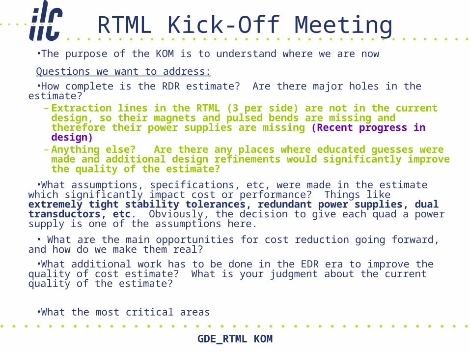
RTML Kick-Off Meeting•The purpose of the KOM is to understand where we are now
Questions we want to address:
•How complete is the RDR estimate? Are there major holes in the estimate? – Extraction lines in the RTML (3 per side) are not in the current design,
so their magnets and pulsed bends are missing and therefore their power supplies are missing (Recent progress in design)
– Anything else? Are there any places where educated guesses were made and additional design refinements would significantly improve the quality of the estimate?
•What assumptions, specifications, etc, were made in the estimate which significantly impact cost or performance? Things like extremely tight stability tolerances, redundant power supplies, dual transductors, etc. Obviously, the decision to give each quad a power supply is one of the assumptions here.
• What are the main opportunities for cost reduction going forward, and how do we make them real?
•What additional work has to be done in the EDR era to improve the quality of cost estimate? What is your judgment about the current quality of the estimate?
•What the most critical areas

27 August 2007 GDE_RTML KOM 3
Goals of the EDR
• Determine the relevant engineering specs for all components and beamlines– Ensure that a documented path from the physics requirements to
the specs exists
• Value engineering – verify that the design and specs represent the best balance between cost and performance– IE, reduce cost through changing design and/or specs
• Reduction of cost and cost uncertainty through engineering– IE, keep design and specs the same and reduce costs through
better engineering to meet the specs
• R & D program and EDR design– Complete the R & D program– Complete an ILC design which incorporates the R & D results and is
generally closer to “ready to build” than the RDR design
• Reduction of risk in the design

27 August 2007 GDE_RTML KOM 4
Goals of the EDR (2)• Original RTML EDR plan (developed for ART) had assumed EDR
was more like a DOE TDR– Requires ~30% of engineering drawings done– Consequently, much effort focused on magnet and beamline
engineering• Did not assume existence of PM Troika
– Effort went into planning for construction• Basically doing PM work in this work package
• Current EDR plan changes the emphasis– No urgent need to get detailed engineering drawings done– RTML leader responsible for developing an execution plan for the
area• RTML upstream areas need to be ready for beam early compared to BC,
ML, BDS– Need to ensure that complete engineering for those areas occurs in a
timely manner– Should be same time scale as sources and DRs– Need to understand timeline requirements from “here are my specs for
this magnet / vacuum chamber / BPM”, to, “Here is the first set of magnets / vacuum chambers / BPMs from the vendor”

27 August 2007 GDE_RTML KOM 5
RTML Cost Distribution• Total cost xxx MILCU per PHG 2007 March xxx
edited out by PHG• Of that:
– CFS: 42%– RF, CM, Cryo: 22 %– Magnets + PS: 20 %– All the rest: 16 %
• Instrumentation, vacuum, dumps, collimators, controls
• Best foci for cost reduction efforts:– BCs (RF and CFS)– Turnaround and Arc (CFS)– Std beamline cells (Magnets + other)
• A distant third
Magnets
+PS
RF, CM,Cryo
CFS

27 August 2007 GDE_RTML KOM 6
Implications of Cost Breakdown• No point doing design engineering on CFS or RF
portions of the cost pie– Already being done in other parts of the WBS
• Might be worth doing design engineering on conventional beamlines– Only 1/3 of RTML total cost …– … and RTML total cost is < 1/10 of ILC cost …– … and resources are tight
• Leaving cost aside, execution plan may (and probably will) demand some work on these areas in near term– Engineering beamline design, – Power, Cooling for CFS– Remember that RTML upstream area is needed for DR
extraction• Implies that DR full-power commissioning cannot occur without
RTML upstream area

27 August 2007 GDE_RTML KOM 7
RTML Risk Areas• Single-Bunch Beam Dynamics
–Studies of beam tuning in BC using 2006 optics missed emittance target by a factor of 2
• 2007 optics will be worse due to longer DR beam–Effects of dynamic misalignments (GM, vibrations, jitters) not
studied yet–Feedback/Feedforward corrections–Stray fields in Return line• Looks okay, but more understanding of fields other than dipole needed
– Is Recycler experience relevant to RTML?• More AC dipole fields would also be useful
–Annoying collective effects not yet resolved• Space charge incoherent tune spread – could cause some failure of global
tuning methods• Resistive wakes in the vacuum chamber – not looked at for Return line yet
–Cavity fields• Wakefield and RF kick from asymmetric coupler discussed at DESY
meeting– Scary!

27 August 2007 GDE_RTML KOM 8
RTML Risk Areas (2)
• Beam-beam collision timing– Need ~0.25° RMS stability of RF systems in
each RTML wrt common master oscillator for 2% loss in integrated luminosity
• For nominal – shorter bunch parameters need correspondingly tighter tolerances
• 0.25° @ 1.3 GHz = 0.53 psec
– Time scale of a few seconds• Assume direct measurement of arrival time at IP +
feedback to correct drifts which are slower than this
– Beam loading compensation• RTML runs far off-crest• When beam arrives, need to change phase and power of
RF station to compensate beam-induced fields and stay at correct voltage and phase

27 August 2007 GDE_RTML KOM 9
RTML Risk Areas (3)• Attainable voltage
– BC2 runs at high gradient• 30.2 MV/m for nominal, 31.0 MV/m for LowN
– If attainable voltage after R & D program is lower, changes are required
• Either more RF units or a lower final energy and consequent poorer emittance performance
• Packing factor of dense areas– Turnaround and DRX arc in particular– If desired packing factor is impossible, either more beamline
length or less optimal optics is needed
• BC1 Wiggler bend magnets– Very wide (~40 cm) good field region desirable
• Allows a wide range of R56 values, much flexibility in BC configuration
– Haven’t fully reviewed this issue since migration to 2007 optics
• Do we still need 40 cm? Would 10-20 cm be enough?
– Highly unusual magnets may be needed!

27 August 2007 GDE_RTML KOM 10
Technical Risks Summary:
Risk Probability Cost, M$ Prob*cost M$
Packing Fraction 30% 12 3.6
Beam motion 10% 2? 0.2
Stray field optics 5% 5? 0.25
Space charge 20%? 5? 1.0
Ion instability 10% 5 0.5
CollWake 10% 5? 0.5
Emittance 75% 10? 7.5
Cavity pitches 50% 20 10
Gradient 75% 16 12
Phase stability 25% 60 15
If I take the sum of (probability * cost) to be the cost risk of the RTML, then I'm looking at a total cost risk of M$ 50.
27 August 2007 GDE_RTML KOM 11
EDR Plan: Working Assumptions
• Concentrate for the work specific for RTML only• In our EDR plans we don’t assume any
design/engineering work already being done by other areas, even if their risk and cost impact are significant for RTML, unless our specs are different:– Cavities, Cryomodules, Cryogenic– HLRF – LLRF– Beam diagnostics
• We will provide specs and will work with technical groups

27 August 2007 GDE_RTML KOM 12
EDR Plan: Working Assumptions (2)
Use existing designs, where it is possible– Revision of existing design– Optimization Performances and Cost– Documentation
• Beam dump design– SLAC Beam Dump East – Radiation water handling, SLAC/SNS
• Pulse kicker, septa, some PS– SLAC, …
27 August 2007 GDE_RTML KOM 13
Proposed RTML EDR Plan
• Beamline design work– Engineered RTML lattice, geometry-matched RTML lattice,
ultra-short BC, magnet envelope estimation• Necessary to really understand what RTML beamline looks like, move
towards final design (EDR goal 4)
• Some value engineering (ultra-short BC is value engineering) (EDR goal 2)
• Necessary to reduce cost uncertainty, since some uncertainty was associated with design immaturity (EDR goal 3)
• Addresses risk in areas with a high packing fraction (EDR goal 5)
– Work load: about 1.5 FTEs in FY08 and 1.5 FTEs in FY09• Cornell would like to supply many of these (all?)
– Don’t know if they’ll get the budget
• Ultra-short BC: Kyungpook National Univ., Korea

27 August 2007 GDE_RTML KOM 14
Alternative bunch compressor Alternative two-stage BC has two rf sections and two chicanes with 4 bending
magnets each. Each chicane includes a 34 m lattice of bending.
Beams with bunch lengths of 6 mm rms and 9 mm rms can be compressed to 0.15 mm rms and 0.3 mm rms in the BC, respectively.
Dispersion correction, orbit correction and skew-correction were performed for emittance tuning in the alternative BC.
- Horizontal and vertical emittance growths due to conservative machine errors are about ~ 10% (8.9 m and 9.1 m due to ISR and ISR+CSR, respectively) and ~4%, respectively.
Eun-San KimKyungpook National Univ., Korea
Review design LET meeting Dec 2007 SLAC

27 August 2007 GDE_RTML KOM 15
Engineering: Tunnel X-section
RTML_BC2 ~0.5km Transferlines
~60cm

27 August 2007 GDE_RTML KOM 16
Proposed EDR RTML Plan (2)
• Specifications Development– Go through lattice and document specs on
each device, beamline, etc• Including path from physics goals of facility to specs• Pre-requisite for overall value engineering effort –
understanding which specs drive costs, which are unknown
– Probably about 0.2 FTE– After that, missing specs need to be filled in
• Probably done in collaboration with accelerator physics effort. Request to Acc Physics group
• Maybe another 0.2-0.3 FTE?

27 August 2007 GDE_RTML KOM 17
Proposed RTML EDR Plan (3)• Accelerator physics studies
– Address risks identified on slide 7– ART plan budgeted 0.5 FTE in FY08, 0.75 FTE in FY09– Probably about right (optimistic)
• Maybe a little light, but > 1 FTE in either year seems excessive
• Value Engineering of high-value targets– Compressors, arcs, and turnarounds– Estimate 0.5 FTE for this
• EDR writing– Actual effort of typing and etc.– Old plan had 0.2 FTE for this– Can probably push into FY10 for Jan 1, 2010 EDR draft
release• Implementation Plan
– ART plan budgeted 0.2 FTE in FY09 for this– More sensibly 0.2 FTE in FY08, 0.3 FTE in FY09

27 August 2007 GDE_RTML KOM 18
C.Adolphsen: ML, Installation and Operation
• Long-range alignment
– Spec for initial linac ‘straightness’ and slow ground
motion
• Trajectory control
– FB and magnet response times based on GM models
• Energy control
– Measuring the beam energy profile and matching the quad
lattice
– Regulation of energy at the end of the linac
• Backgrounds and machine protection
– Halo, SR, MP, dark currents, spoilers and beam abort
.
.
.

27 August 2007 GDE_RTML KOM 19
CA: ML, Wakefield/Cavity Topics
• Wake offset due to FPC/HOM antennae intrusions
• HOM absorber versus beam pipe losses
• Simulation of multi-cavity trapped modes
• Simulation of first/second band dipole mode properties and dipole mode data analysis
• Design of a lower R, E field and B field cavity with 60 mm irises
• Multipacting simulations in couplers and HOMs
• Surface magnetic field enhancement due to cell-to-cell misalignments

27 August 2007 GDE_RTML KOM 20
Proposed RTML EDR Plan (4)
• Total is about 2.8 FTE per year for 2 years– About k$ 525 / year at SLAC or FNAL– About k$ 315 / year at LEPP
• Faculty salaries covered during school year• Grad students will work for food
• Far less than plan presented to ART– K$ 625 in FY08 and k$ 1758 in FY09– Leaves out serious magnet engineering from
old ART plan• Is this OK?

27 August 2007 GDE_RTML KOM 21
ART WBS x.6 FY 08-09 Budget
FY08FY08FY08 FY09 FY09FY09 ContinuesPriorityFTE DirectTotal FTE DirectTotal in FY10
WBS WBS(WP)Description Lab Range 1-3M&S M&SK$ k$ K$ k$
2.6.1 Acc design2.6.1.1 Engineered RTML lattice SLAC + TBD1 0.3 0 55.02 0.45 0 85.48 Y2.6.1.2 Ultra-short bunch compressor LEPP 2 0.5 3 58.83 0.5 3 60.42 N2.6.1.3. Beam tails LEPP 2 0.5 2 57.24 0.5 2 58.83 N2.6.1.4 Lattice design for EDR geometry LEPP 1 0.5 3 58.83 0.5 2 58.83 Y2.6.1.5 EDR Writing SLAC 1 0.1 0 18.34 0.2 10 39.00 Y2.6.1.6 Preparation for Construction SLAC+TBD1 0 0 0 0.2 10 49.49 Y
2.6.2 Accelerator component design and engineering2.6.2.1 Magnet envelope estimation SLAC 1 0.2 0 36.68 0 0 0.00 N2.6.2.2 Beamline rough layout SLAC 1 0.1 0 18.34 0 0 0.00 N2.6.2.3 Std quad engineering design SLAC 1 1.4 0 256.8 0 0 0.00 N2.6.2.4 Dummy CavBPM Design SLAC 2 0.4 0 64.19 0 0 0.00 N2.6.2.5 DRX Arc bend engineering design TBD 1 0 0 0 1.4 0 265.93 N2.6.2.6 Std corrector engineering design TBD 2 0 0 0 0.65 0 123.47 N2.6.2.7 Tuning quad engineering design TBD 2 0 0 0 0.65 0 123.47 N2.6.2.8 DRX Arc Half-Cell Integration Design TBD 2 0 0 0 0.2 0 37.99 N2.7.2.9 BC1 Wiggler Bend 1 engineering design TBD 2 0 0 0 0.65 0 123.47 N2.6.2.10 BC1 Wiggler bend 2 engineering design TBD 2 0 0 0 1.9 0 360.91 N2.6.2.11 BC1 wiggler half-cell integration design TBD 2 0 0 0 0.4 0 75.98 N2.6.2.12 Return line quad engineering design TBD 2 0 0 0 0.65 0 123.47 N2.6.2.13 Return Line Quad Pkg Integration Design TBD 2 0 0 0 0.4 0 75.98 N2.6.2.14 DRX Arc In-Tunnel Integration Design TBD 3 0 0 0 0.5 0 94.975 Y
Proposed ART work packages WBS x.6 and x.7. Probably needs revision

27 August 2007 GDE_RTML KOM 22
ART WBS x.7 FY 08-09 Budget
FY08FY08 FY08 FY09 FY09 FY09WBSWBSWBS(WP) Description FTE M&S Total FTE M&S Total
k$ k$ k$ k$2.7 Acc. Design
2.7.2.1 Wakefields studies at SLAC 1.5 0 275 1 0 1902.7.2.2 Wakefields studies at FNAL 0.5 0 90 1 0 190
2.7.3 Acc. Physics2.7.3.3 RTML Emitance preserv study 0.50 0 92 0.75 0 1422.7.3.4 RTML Emitance tuning - LEPP 1.00 3 109 1.00 3 1122.7.3.5 Start-to-end simulations - FNAL 0.75 0 135 1.00 0 190
2.7.5 2.7.3.6 Start-to-end simulations - SLAC 0.50 0 92 0.75 0 1422.7.3.7 Dark current and MPS 0.00 0 0 0.35 0 66
3.7 R&D3.7.2.1 L-band BPM design and test 1.25 50 238 1.4 110 393
3.7.1 Quad package test3.7.1.1 SC Quad prototype and tests 1.25 40 272 1.8 80 4343.7.1.2 SC Corrector prototype and tests 1 30 215 0.8 37 180
WBS x.7 work packages related to RTML

27 August 2007 GDE_RTML KOM 23
Proposed RTML EDR Plan (5)• Magnet packages
– Design of the all magnets• EM parameters, field quality• Dimensions for lattice engineering design• Power and Cooling requirements.• Integrated Correctors ? (build-in vs. separate)
– Prototyping of the most critical or costing components to prove performance/technology or better cost estimation (?)
• SC solenoid in spin rotators: B=5 T. Short (0.5m) section to demonstrate technology
• SC quad/corrector for RTML cryomodules, demonstrate center stability, prove technology (in WBS x.7)
• Q20L200 – (~1500 magnets in RTML) cost impact• D25L900V3 - Wide aperture (40cm) bends in BC
27 August 2007 GDE_RTML KOM 24
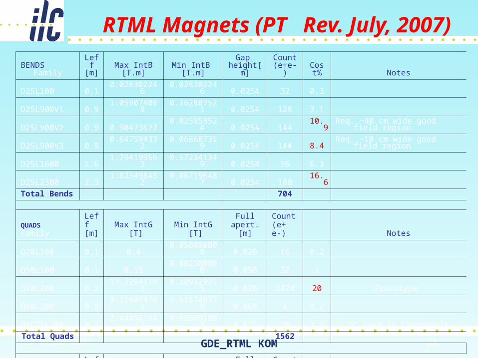
RTML Magnets (PT Rev. July, 2007)BENDS
FamilyLeff [m]
Max IntB[T.m]
Min IntB [T.m]
Gap height[m]
Count (e+e-)
Cost% Notes
D25L100 0.1 0.028302246 0.028302246 0.0254 32 0.3
D25L900V1 0.9 1.059074088 0.162887521 0.0254 128 3.1
D25L900V2 0.9 0.90473627 0.025859524 0.0254 144 10.9 Req. ~40 cm wide good field region
D25L900V3 0.9 0.647594332 0.068687319 0.0254 144 8.4 Req. ~10 cm wide good field region
D25L1600 1.6 1.794199563 0.572341349 0.0254 76 6.3
D25L2300 2.3 1.823498432 0.067196487 0.0254 180 16.6
Total Bends 704
QUADSFamily
Leff [m]
Max IntG [T]
Min IntG [T]
Full apert. [m]
Count (e+ e-) Notes
Q20L100 0.1 0.4 0.050000000 0.020 16 0.2
Q50L100 0.1 0.15 0.002500000 0.050 32 1
Q20L200 0.2 17.72946193 0.209329715 0.020 1474 20 Prototype
Q60L200 0.2 3.714074761 1.815746779 0.060 4 0.2
QSC75L200 0.2 2.444561947 0.659891993 0.075 36 3.6 SC Quad in Cryomodule
Total Quads 1562
DC CorrectFamily
Leff [m]
Max IntB [T.m]
Min IntB [T.m]
Full apert. [m]
Count (e+e-) Notes
D20L50 .05 0.05318839 0.000627989 0.020 2240 23 separated or build-in? Need R&D
DSC75L200 0.2 0.00733369 0.001979676 0.075 54 2.2 SC Corrector in Cryomodule
Total Correct 2294
27 August 2007 GDE_RTML KOM 25
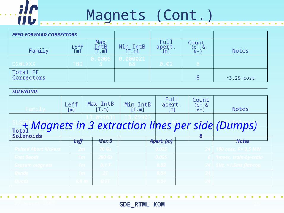
Magnets (Cont.)FEED-FORWARD CORRECTORS
FamilyLeff [m]
Max IntB [T,m]
Min IntB [T.m]
Full apert. [m]
Count (e+ & e-) Notes
D20LXXX TBD 0.00063 0.00002168 0.02 8
Total FF Correctors 8 ~3.2% cost
SOLENOIDS
FamilyLeff [m]
Max IntB [T,m]
Min IntB [T.m]
Full apert. [m]
Count(e+ & e-) Notes
SLSC50L2600 2.6 13.0990313 13.0990313 0.05 8 SC Solenoid
Total Solenoids 8
Leff Max B Apert. [m] Notes
Pulsed Abort Kickers 2m 70 Gs 0.025 24 100 nsec, P= 0.5 MW
Fast Bends 1m 280 Gs 0.025 6 1msec, train-by-train
Septum magnets 1m 0.1 T 0.03 24 5Hz, >1.5ms flat-top
Bends 1m 2T 0.04 24
Quads 0.8 m 0.9T 0.04 24
+ Magnets in 3 extraction lines per side (Dumps)
27 August 2007 GDE_RTML KOM 26
RTML Magnets R&D (V.Kashikhin)
• All RTML magnets are feasible for design and fabrication.
• Total number of magnets 4576.
• Number of magnet styles: Dipoles- 6, Quadrupoles – 4 plus 1 –SC, Correctors – 2 plus 1 SC, 1 SC solenoid, plus septums, bumps and kickers.
• Time frame for the magnet design depends on many factors (region, firm, institution, salary range, experience, supporting structure, etc.) and better use bidding process to resolve this issue.
• Magnets for R&D and prototyping: 1- conventional dipole, 1- conventional quadrupole, 1- corrector, 1- superconducting quadrupole package including correctors, 1- superconducting solenoid 0.5 m model.
• Goals for R&D: prove chosen magnet technology, reliability, investigate magnetic center stability in quadrupoles at BBA, hysteresis effects in dipoles, prove the chosen magnetic measurement technique. Investigate coupling effects between main magnet and correctors. Investigate the magnets long term behavior.
27 August 2007 GDE_RTML KOM 27
Proposed RTML EDR Plan (6)
• Studies of Beam-beam collision timing– Need ~0.25° RMS stability of RF systems in
each RTML wrt common master oscillator for 2% loss in integrated luminosity
– One or two RF systems (1 or 2 CMs)– Study stability of RF system, when beam– Experiment at TTF/DESY or NML/FNAL or KEK– Need more detailed plans– Resources ~ (???)

27 August 2007 GDE_RTML KOM 28
Two RF systems• Suggested by Tom Himel and PT. Idea- run two system 180° apart• Allows to evaluate two systems with respect to each other – just like we
need for the electron and positron BC’s• Relaxes the bunch arrival requirements• If both systems are run at equal amplitudes, the correlated energy
spread is canceled• The phase jitter of one system with respect to another will show up as
the energy jitter of the beam.• Use energy spectrometer to evaluate the beam energy
300 200 100 0 100 200 30040
30
20
10
0
10
20
30
40
Time, ps
Vol
tage
, MV
V t( )
t
.
300 200 100 0 100 200 30040
30
20
10
0
10
20
30
40
Time, ps
Vol
tage
, MV
V t( )
t
.
RF 1 RF 2
S.Nagaitsev
27 August 2007 GDE_RTML KOM 29
Conclusions
• For a single RF unit:– Need a bunch compressor to resolve 0.05-degrees or
100-fs. Bunch length of 1-ps should work, 10-ps will not.
– Can not run beam close to zero-crossing because of energy spread induced by rf slope and low injection energy.
– Need also to measured the incoming bunch-to-bunch energy jitter so this calls for dispersive section (a compressor) before the CM
• For two RF units:– Need two rf units or, at least, two rf systems powering
two cryomodules– Does not require bunch arrival jitter measurements.– Can run beam at zero-crossing
27 August 2007 GDE_RTML KOM 30
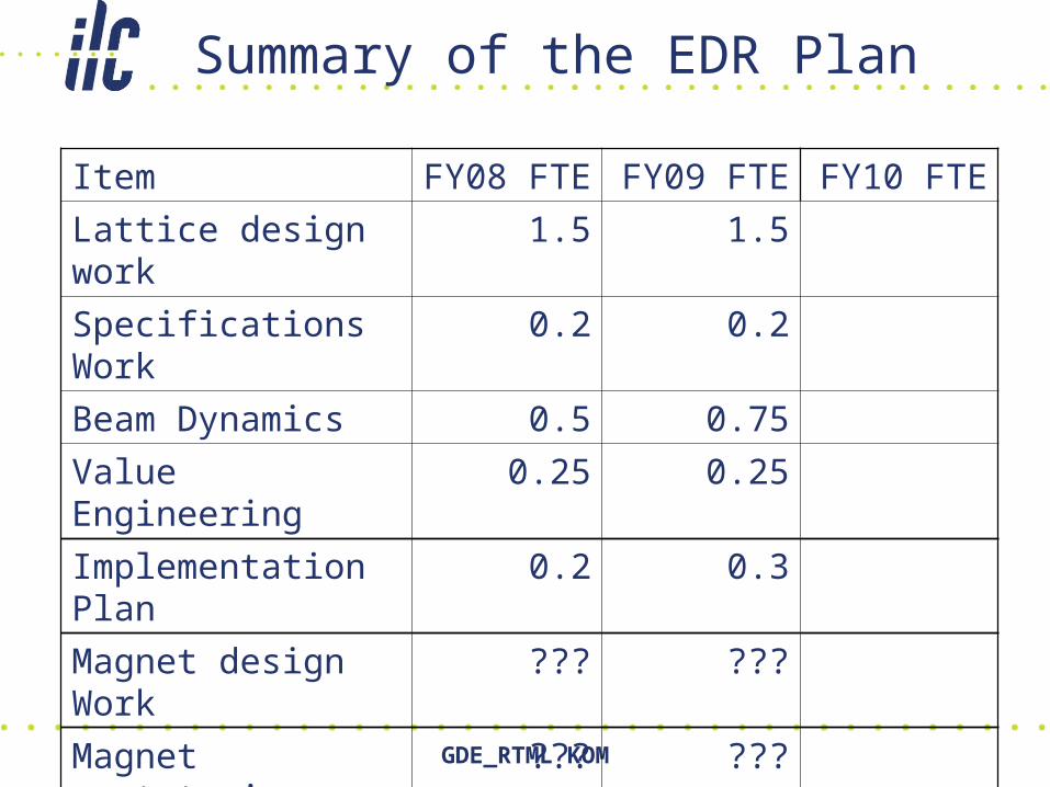
Summary of the EDR Plan
Item FY08 FTE FY09 FTE FY10 FTE
Lattice design work 1.5 1.5
Specifications Work 0.2 0.2
Beam Dynamics 0.5 0.75
Value Engineering 0.25 0.25
Implementation Plan 0.2 0.3
Magnet design Work ??? ???
Magnet prototyping ??? ???
Coll Timing studies ??? ???
Total 2.65+? 3.00+?

27 August 2007 GDE_RTML KOM 31
People• Optics Design
Peter Tenenbaum -- optics design of most sections, parameter selection for BC1 and BC2Jeff Smith -- spin rotatorMark Woodley -- skew correction and diagnostic section after the spin rotator, match from BC1 to BC2 RF and from BC2 RF to BC2 wigglerSergei Seletskiy -- BC1 and BC2 wigglers, new pulsed extraction lines (in progress)Eun-San Kim -- ultra-short bunch compressor
• Engineering Vladimir Kashikhin -- DC magnetsPaul Bellomo -- DC power suppliesTom Mattison -- fast kickers, septa, dump sweepers, and power supplies for these magnetsYusuke Suetsugu -- original vacuum system design for turnaround, warm areas of BC/BC2, pulsed extraction linesJohn Noonan -- vacuum system design for Return linesPaolo Michelato -- vacuum system for cryomodules
Tom Markiewicz -- dumps, stoppers, and collimatorsRay Larsen -- 1.3 GHz RF sources (klystrons and modulators)Manfred Wendt -- Instrumentation, including dipole-mode cavities and power sources for them
John Carwardine -- original work on RTML controlsClaude Saunders -- later work on RTML controls
Tom Peterson -- cryogenicsFred Asiri -- installation
Jean-Luc Baldy -- main contact on CFSGerry Aarons -- additional contact on CFSTom Lackowski -- contact on CFS, mainly for area near DR
Gerry Dugan – engineered RTML Layout
27 August 2007 GDE_RTML KOM 32
People (2)
• Performance
Peter Tenenbaum -- dispersion control upstream of BC1, emittance preservation in BC1-BC2, collimator wakefieldsJeff Smith -- dispersion and coupling control upstream of BC1, spin preservationKiyoshi Kubo -- dispersion control upstream of BC1, emittance preservation in BC1-BC2, stray field effectsAndrea Latina -- emittance preservation in BC1-BC2Eun-San Kim -- emittance preservation in ultra-short BCLanfa Wang -- estimates of ion instabilities and electron cloud effectsPanagiotis Spentzouris -- space charge (in progress)Marco Venturini -- space charge (in progress)Sergei Seletskiy -- beam-gas scattering Gerry Dugan - emittance preservation