2.6. survival rate and fracture strength of porcelain veneers
TRANSCRIPT

Aus der Universitätsklinik für Zahn-, Mund-, und Kieferheilkunde der
Albert-Ludwigs-Universität Freiburg
Abteilung für Zahnärztliche Prothetik
(Ärztl. Direktor: Prof. Dr. J. R. Strub)
Survival rate and fracture strength of maxillary incisors,
restored with different kinds of full veneers.
An in-vitro study
INAUGURAL-DISSERTATION
zur Erlangung des
Zahnmedizinischen Doktorgrades
Der Medizinischen Fakultät der Albert-Ludwigs-Universität
Freiburg
Vorgelegt 2003
Von
Nektaria Stathopoulou
Geboren in Athen, Griechenland
Dekan: Prof. Dr. med. J. Zentner
1. Gutachter: Prof. Dr. J. R. Strub
2. Gutachter: PD. Dr. P. Hahn
Jahr der Promotion: 2003

To my parents and my brother

Table of contents:
1. Introduction...................................................................................................... 1
2. Literature review ............................................................................................. 2
2.1 Historic perspective .................................................................................... 2
2.2 Indications and contraindications of porcelain veneers........................ 3
2.3 Classification of currently available all-ceramic systems for porcelain
veneers................................................................................................................ 5
2.3.1. Sintered ceramics .................................................................................................... 5
2.3.2. Infiltrated ceramics................................................................................................. 7
2.3.3. Castable ceramics.................................................................................................... 8
2.3.4. Pressable ceramics ................................................................................................ 10
2.3.5. Machining techniques .......................................................................................... 11
2.3.5.1. Copy-milling technique.............................................................. 11
2.3.5.2. CAD/CAM Systems ................................................................... 12
2.4. Preparation design................................................................................... 14
2.5. Luting procedure ..................................................................................... 18
2.5.1. Conditioning of the ceramic surface .................................................................. 18
2.5.2. Conditioning of the tooth surface....................................................................... 19
2.5.3. Luting composite .................................................................................................. 21
2.5.4. The adhesion complex: tooth/luting composite/porcelain ........................... 22
2.6. Survival rate and fracture strength of porcelain veneers................... 22
2.6.1. Biting forces and range of temperature on anterior dentition ....................... 22
2.6.2. Survival rate of porcelain veneers...................................................................... 23
2.6.3. Fracture strength of porcelain veneers .............................................................. 24
3. Aim of the study ............................................................................................ 27
4. Materials and Methods ................................................................................ 28
4.1. Materials .................................................................................................... 28
4.1.1. Abutment teeth ..................................................................................................... 28
4.1.2. Ceramic system ..................................................................................................... 28
4.1.3. Luting agent........................................................................................................... 29
4.1.4. Impression materials ............................................................................................ 31
4.1.5. Die materials.......................................................................................................... 31
4.1.6. Additional materials used ................................................................................... 32
4.2. Methods..................................................................................................... 32
4.2.1. Teeth ....................................................................................................................... 32
4.2.1.1. Selection of the abutment teeth ................................................. 32
4.2.1.2. Diagnostic Wax-up...................................................................... 33
4.2.1.3. Tooth preparation........................................................................ 33
4.2.2. Fabrication of the master models ....................................................................... 36
4.2.2.1. Impression .................................................................................... 36
4.2.2.2. Fabrication of the master dies.................................................... 36
4.2.3. Fabrication of the veneers.................................................................................... 36
4.2.3.1. Wax-up.......................................................................................... 36
4.2.3.2. Investment .................................................................................... 37
4.2.3.3. Preheat and Pressing................................................................... 37
4.2.3.4. Divestment ................................................................................... 38
4.2.3.5. Glazing.......................................................................................... 38
4.2.4. Cementation of the veneers................................................................................. 39
4.2.4.1. Pre-treatment of the veneers (Fig. 4.5) ..................................... 39
4.2.4.2. Pre-treatment of the abutments (Fig. 4.6) ................................ 39
4.2.4.3. Bonding procedure (Fig. 4.7) ..................................................... 40
4.2.5. Preparing the test specimens for the artificial-mouth ..................................... 41
4.2.5.1. Artificial periodontal membrane .............................................. 41
4.2.5.2. Fabrication of the master models for the artificial mouth..... 41
4.2.6. Dynamic loading in the artificial mouth ........................................................... 42
4.7. Examination of post-bonding cracks..................................................... 46
4.8. Fracture strength test (Fig. 4.12)............................................................. 46
4.9. Statistic analysis of data .......................................................................... 47
5. Results ............................................................................................................. 47
5.1. Dynamic loading in the artificial oral environment............................ 47

5.1.1. Survival rate .......................................................................................................... 47
5.1.2. Crack development .............................................................................................. 50
5.1.2.1. Crack formation rate (Fig. 5.3)................................................... 50
5.1.2.2. Crack pattern of porcelain veneers (Table 5.1)........................ 52
5.2. Fracture strength test............................................................................... 54
5.2.1. Fracture strength of individual samples ........................................................... 54
5.2.2. Statistical evaluation of data ............................................................................... 57
5.2.3.1. Component of the restoration that failed................................. 60
5.2.3.2. Position of the restoration where fracture occurred .............. 62
6. Discussion....................................................................................................... 64
6.1. Discussion of the materials..................................................................... 64
6.1.1. Extracted human teeth as abutments................................................................. 64
6.1.2. The storage solution ............................................................................................. 65
6.1.3. EPC as a material for the fabrication of full veneers ....................................... 65
6.2. Discussion of the methods...................................................................... 66
6.2.1. Preparation of the specimens for the artificial mouth..................................... 66
6.2.1.1. Preparation ................................................................................... 66
6.2.1.2. Cementation ................................................................................. 68
6.2.1.3. Artificial membrane .................................................................... 69
6.2.2. Dynamic loading in the artificial mouth ........................................................... 70
6.2.2.1. Angulation in the artificial mouth ............................................ 70
6.2.2.2. Contact point of the applied force in the artificial mouth ..... 71
6.2.2.3. Artificial ageing and its clinical relevance on the survival rate
of ceramic veneers .................................................................................... 71
6.2.3. Load-to-fracture testing ....................................................................................... 73
6.2.3.1. Angulation in the Zwick testing machine................................ 73
6.2.3.2. Contact point of the load-to-fracture applied force................ 73
6.2.3.3. Clinical relevance of the fracture strength tests of ceramic
veneers ....................................................................................................... 74
6.3. Discussion of the results ......................................................................... 75
6.3.1. Dynamic loading in the artificial mouth ........................................................... 75

6.3.1.1. Survival rate ................................................................................. 75
6.3.1.2. Crack formation........................................................................... 76
6.3.2. Load-to-fracture testing ....................................................................................... 78
6.3.2.1. Fracture strength of the specimens in the Zwick universal
machine...................................................................................................... 78
6.3.2.2. Fracture pattern of the specimens in the Zwick universal
machine...................................................................................................... 79
7. Conclusions .................................................................................................... 81
8. Summary ......................................................................................................... 82
9. Zusammenfassung ........................................................................................ 83
10. References..................................................................................................... 84
11. Curriculum vitae.......................................................................................... 97
12. Acknowledgements .................................................................................... 98

Introduction 1
1. INTRODUCTION
The publics demand for the treatment of unaesthetic anterior teeth is
steadily growing. Accordingly, several treatment options have been
proposed to restore the aesthetic appearance of the dentition. For many
years, the most predictable and durable aesthetic correction of anterior
teeth has been achieved with full crowns. However, this approach is
undoubtedly the most invasive, requiring removal of large amounts of
sound tooth structure and resulting in possible adverse effects on the pulp
and adjacent periodontal tissues.
The introduction of multi-step total-etch adhesive systems, along with the
development of high-performance hybrid resin composites has led to a
more conservative restorative technique. Resin composite veneers can be
used to mask tooth discoloration and/or to correct unaesthetic tooth form
and/or position. However, such restorations still suffer from a limited
longevity, since resin composites remain suspect to discoloration, wear
and marginal fractures.
In search for more durable aesthetics, porcelain veneers have been
introduced. Several studies have proven their long time prognosis in-vivo
and high level of patient acceptance (Rucker et al. 1990; Calamia 1993;
Fradeani 1998; Friedman 1998; Kihn and Barnes 1998; Peumans et al. 1998b;
Dumfahrt and Schaffer 2000). The failure rate ranged in these studies ranged
between 0% (Rucker et al. 1990) and 33% (Shaini et al. 1997). Additionally,
in-vitro studies demonstrated long term retention of porcelain veneers
(Magne and Douglas 1999c; Castelnuovo et al. 2000; Hahn et al. 2000).
Despite the promising results, there are certainly limits to the possibilities
that veneers can offer. Key factors for prognosis are the material and the

Literature review 2
kind of preparation used for such restorations. There are limited studies
concerning the design and thickness of the preparation. Regarding the
design of the preparation, four basic types have been described: the
window, the feather, the bevel and the overlapped incisal edge
preparation. As far as the thickness of preparation is concerned, the early
concepts suggested minimal or no tooth preparation. Nevertheless,
current beliefs support removal of varying amount of tooth structure.
Further studies are required to evaluate the influence of ceramic materials
and different types of preparation on the survival rate and fracture
strength of laminate porcelain veneers.
2. LITERATURE REVIEW
2.1 Historic perspective
Dr Charles Pincus (1938) was the first to describe the use of veneers to
enhance the appearance of actors for close-ups in the movie industry.
They were temporarily held in place with adhesive denture powder while
the actors were before a camera. The fragile restorations then had to be
removed, because no adhesive system existed at that time to provide a
permanent attachment of veneers to tooth structure.
Buonocore´s (1955) research on acid-etch techniques, combined with
Bowen´s (1978) later use of filled resin, enabled the mechanical bonding
between etched tooth and filled resins. The use of direct resin veneers was
now possible. The limitation of the self-curing technique was the limited
working time for the dentist to recreate a labial surface before the
composite resin chemically cured itself. The introduction of light-cured
composite resins allowed the dentist greater flexibility, due to a greater
working time and improved chemistry.

Literature review 3
Faunce and Meyers (1976) described a one-piece acrylic resin prefabricated
veneer as an improved alternative to a direct acid-etched bonded veneer.
By using a chemical primer applied to the veneer and a composite resin to
lute the veneer onto an etched tooth, both chemical and mechanical
bonding contributed to the attachment.
The concept of acid-etching porcelain was cited in the dental literature,
when Rochette described the restoration of a fractured incisor with an
“etched silanted porcelain block” (1975). Essential to the attachment of
porcelain veneers is the ability of porcelain to be etched and bonded to
composite resin as reported by Horn (1983) and Simonsen and Calamia
(1983). Continued research by Calamia (1985) also showed that the
treatment of the etched porcelain veneer with a silane coupling agent
produced a chemical bond that enhanced the porcelain-composite resin
mechanical bond.
From the moment porcelain veneers could be adhesively luted, the clinical
and laboratory techniques have continued to be refined. Today we have at
our disposal long term in-vivo and in-vitro studies focusing on porcelain
veneers, performed during the last 10 to 15 years (Karlsson et al. 1992;
Nordbo et al. 1994; Jäger et al. 1995; Fradeani 1998; Friedman 1998; Peumans et
al. 1998b). Furthermore, new preparation designs and extensions of
porcelain veneers are tested (Magne and Douglas 1999c).
2.2 Indications and contraindications of porcelain
veneers
According to the last classification of Belser et al. (1997), the three principal
indications for porcelain veneers are:
Literature review 4
Type I: Tooth discoloration resistant to vital bleaching procedures
Examples of type I indications include heavily discoloured teeth due to
tetracycline therapy [degrees III and IV according to Jordan and Boksman
(1984)], fluorosis and amelogenesis imperfecta (Calamia 1988). Anterior
teeth that present severely worn down edges, that subsequently lead to an
infiltration of dentine also belong to the same category.
Type II: Major morphological modifications
Type II a: Conical teeth
Type II b: Diastema and open embrasures to be closed
Type II c: Augmentation of incisal length and prominence
In the above cases, a single isolated problem can easily be handled with
the free-hand application of composite resins. However, in the case of
multiple modifications, the use of composites does not permit the control
of form, shade or colour and also presents signs of early fatigue when
used to restore incisal edges. Porcelain laminate veneers offer a more
predictable result.
Type III: Extensive restorations
Type III a: Extensive coronal fracture
Type III b: Extensive loss of enamel by erosion and wear
Type III c: Generalized congenital and acquired malformations

Literature review 5
In these situations, the tooth damage sometimes involves the major part of
the coronal volume or of the tooth surface. The primary advantage of
porcelain laminate veneers is that the vitality of the tooth is maintained.
Nevertheless, there are cases where porcelain veneers are contraindicated.
An extensive reduction of natural tooth structure, in extended caries and
multiple fillings, often requires a full crown because the enamel surface is
not enough to support a resin bonding procedure. Also, in patients with
bad oral hygiene and inadequate compliance veneers should be avoided
(Castelnuovo et al. 2000). Being an aesthetic treatment option, it should be
carried out under the complete collaboration of the patients, who demand
a refined appearance of their dentition.
Furthermore, patients with deep bites, open bites or bruxism are also
contraindicated, because pathological forces are placed on the teeth, that
can lead to fracture of the ceramic veneers (Sheets and Taniguchi 1990;
Fradeani and Barducci 1996).
2.3 Classification of currently available all-ceramic
systems for porcelain veneers
According to the fabrication procedure, the all-ceramic systems used for
porcelain veneers are:
2.3.1. Sintered ceramics
These products are available as powders to which the technician adds
water to produce a slurry. The ceramic mass is built up in layers on a
platinum foil or a refractory die material to form the restoration. The
Literature review 6
powders are available in various shades and translucency, and are
supplied with characterizing stains and glazes.
• Feldspathic porcelain
Vitadur N (Vita, Bad Säckingen, D) was one of the first feldspar ceramic
systems used for the fabrication of veneers (McLean and Sced 1987; Gilde et
al. 1989; Rucker et al. 1990; Hui et al. 1991). As per the technique described
by McLean and Scen (1987), a platinum foil of 0.02 mm is placed and
burnished to adapt to the die. The ceramic mass is then layered on the foil.
During sintering, microporosities are formed on the surface of the veneer,
which decrease the strength of the restoration. Thus, the clinical use of this
material is nowadays strongly limited.
• Optec HSP (Jeneric/Pentron, Wellingford, Connecticut, USA)
Optec is a leucite reinforced feldspar ceramic that condenses like an
alumina ceramic and is sintered like a traditional feldspar ceramic. The
leucite concentration was reported to be 50.6 wt% (Kelly et al. 1996). Due to
the higher amount of leucite crystals, it has greater strength than
conventional feldspathic porcelain. Because of its increased strength, it
does not require a core when used to fabricate all-ceramic restorations.
The leucite and glassy components are fused together during the baking
process at 1020°-1035°C. The build-up and contouring of the crown is
accomplished using the powder-slurry technique on a special semi-
permeable refractive die (Kühn 1992; Rosenblum and Schulman 1997). The
body and incisal porcelains are pigmented to provide the desired shade
and translucency.
Optec is recommended for the fabrication of inlays, onlays and veneers
(Schäffer 1990; Anusavice 1993). A flexural strength of 146 MPa has been

Literature review 7
reported for this material, but no survival rate data is available in the
literature.
• Duceram LFC (Ducera Dental, Rosbach, D)
Duceram is a low-fusing hydrothermal ceramic material composed of an
amorphous glass containing hydroxyl ions. The restoration is made in two
layers. The base layer is Duceram Metal Ceramic (a leucite-containing
porcelain) that is placed on a refractory die using standard powder-slurry
techniques and then baked at 930°C. Duceram LFC is applied over the
base layer using the powder-slurry technique and baked at a relatively
low temperature (660°-680°C). The material is supplied in various shades
and can be surface-characterized with compatible stains and modifiers.
Duceram is recommended for inlays, full-contour crowns and veneers
(Rosenblum and Schulman 1997). A flexural strength of 110 MPa has been
reported for this material. No survival rate data for veneers is available in
the literature.
2.3.2. Infiltrated ceramics
These products consist of two components: a powder, which is fabricated
into a porous substrate, and a glass, which is infiltrated at high
temperature into the porous substrate. The infiltrated ceramic is then
veneered, using the conventional feldspathic porcelain technique.
• In-Ceram Spinel (Vita, Bad Säckingen, D)
This glass-infiltrated ceramic is based on spinel, a composition containing
aluminum oxide and magnesium oxide. The powder is mixed with
distilled water to form a thick slip. The slip mass is placed on a refractory

Literature review 8
die and heat-treated at 1120°C for 10 hours to produce the opaque, porous
core. Then an appropriate shade of glass powder is applied to the core
which is baked again at 110°C for four hours. During this process the
molten glass infiltrates the porous alumina core by capillary action. This
procedure increases the strength of the core to about 20 times to its
original strength. The spinel crystals limit crack propagation and the glass
infiltration reduces porosity. Vitadur Alpha (Vita, Bad Säckingen, D)
aluminous veneering porcelain is then applied using conventional
powder-slurry techniques to create the proper shade and contour. The
core of spinel is not etchable. Sandblasting and tribochemical silica coating
is recommended for this material before its adhesive luting.
In-Ceram Spinel is the most translucent material among the glass
infiltrated sintered alumina ceramics and is therefore indicated for
veneers. Nevertheless, some strength has been sacrificed for the
translucency. The flexural strength of In-Ceram is reported to be 450 MPa
and that of In-Ceram Spinell 350 MPa. No survival rate data is available in
the literature.
2.3.3. Castable ceramics
These products are supplied as solid ceramic ingots, which are used for
the fabrication of cores or full-contour restorations using a lost-wax and
centrifugal casting technique. Generally, a monotone shade is available,
which is then veneered with conventional feldspathic porcelain or is
stained to obtain the proper shading and characterization of the final
restoration.
• Dicor (Dentsply, York, Pennsylvania, USA)

Literature review 9
Dicor ceramic is a polycrystalline glass-ceramic (45% glass phase and 55%
crystal phase). Its main component is silica that contains tetrasilicic
fluormica crystals. It is initially moulded as a glass (vitreous phase) and
subsequently heat treated under controlled crystallisation conditions to
produce a glass-ceramic material (mica phase) (Kelly et al. 1996; Rosenblum
and Schulman 1997). The fabrication method uses the lost-wax and
centrifugal casting techniques similar to those used to fabricate alloy
castings. A full contour transparent glass restoration is cast at 1350°C, then
is heat treated at 1075°C for 10 hours. To achieve the appropriate shade,
the extrinsic stains are baked on the surface of the glass-ceramic material
(Rosenblum and Schulman 1997).
The flexural strength of this ceramic material has been reported to be 152
MPa. Barnes et al. (1992) investigated in a short-term clinical study the
efficacy of the Dicor system for the fabrication of veneers. Although
limited survival rate data is available for inlays and crowns, no data is
available for veneers. This ceramic system has not further evolved,
especially for porcelain veneers and its clinical use is rather limited.
• Cera-Pearl (Kyocera Bioceram, Kyoto, Japan)
Cera-Pearl is a castable ceramic similar to the Dicor. It is an apatite ceramic
and its crystal phase is a hydroxyapatite phase in contrast to Dicor´s mica
phase (Hobo and Iwata 1985). The fabrication is also based on the lost wax
and centrifugal casting procedures. It is moulded at 1460°C and heat
treated at 870°C, similar to the Dicor technique. No data is available about
this ceramic system and its clinical use is also limited.

Literature review 10
2.3.4. Pressable ceramics
These products are also supplied as ceramic ingots. They are melted at
high temperatures and pressed into a mould, using the lost-wax
technique. The pressed form can be made to full contour, or can be used as
a substrate for conventional feldspathic porcelain build-up.
• IPS Empress®
IPS Empress® is a leucite reinforced glass ceramic designed for the
fabrication of single crowns, inlays and veneers (Dalloca and Demolli 1994).
The glass-ceramic ingot is partially precerammed by the manufacturer and
then processed in the laboratory and completed, using either a surface-
coloration or layering technique.
A full contour restoration is waxed-up, invested and placed in a special
mould that has an alumina plunger. After wax elimination, the glass-
ceramic is pressed into the preheated muffle. A temperature of 1050°C is
required for pressing the complete form, and a temperature of 1180°C is
required if the layering technique is to be used. Both techniques require 5
bar pressure for 30 to 40 minutes. When the layering technique is used, the
substructure is covered with dentine and enamel porcelain followed by a
final glazing cycle. For the surface-coloration technique, the restoration
form is obtained directly from the wax-pattern (Dong et al. 1992).
This glass ceramic material presents high optical and aesthetic qualities
(Fradeani and Barducci 1996). It shows also an abrasion behaviour close to
that of enamel (Wohlwend and Schärer 1990a). The marginal fit of IPS
Empress veneers has been reported to be relatively good at 95 µm (Schmalz
et al. 1994). Furthermore, Castelnuovo et al. (2000) reported mean fracture
loads between 164 N and 274 N for maxillary incisors restored with IPS
Empress® veneers. Hahn et al. (2000) reported fracture strength values

Literature review 11
between 466 N and 693 N for mandibular incisors restored with IPS
Empress® veneers. However, no survival rate data was mentioned in the
literature.
2.3.5. Machining techniques
In order to eliminate the necessary time and effort to manufacture a
restoration, machining techniques have become an option in the field of
veneer fabrication. Both precision copy-milling machines and CAD/CAM
system are commercially available.
2.3.5.1. Copy-milling technique
• Celay (Mikrona Technologies AG, Spreitenbach, CH)
In this technique the model (pro-veneer) is formed using a light-cured
resin on the master model. Based on the size of the piece to be copied, an
appropriate prefabricated ceramic block is pre-selected and fixed in the
milling unit. The model is fixed in a special attachment unit and a three-
dimensional construction is copied, by means of mechanical censoring and
synchronous milling under water cooling (Grüninger 1996).
For veneers, Alumina Celay® Blanks (Vita, Bad Säckingen, D) are
recommended. Alumina Celay blanks are ingots of a fine-grained
feldspathic porcelain. The milled copings are veneered with aluminous
porcelain (Vitadur Alpha, Vita, Bad Säckingen, D) (Eidenbenz et al. 1994).
Unfortunately, no data is mentioned in the literature concerning veneers.

Literature review 12
2.3.5.2. CAD/CAM Systems
• Cerec (Siemens, Bensheim, D)
Mörmann and Brandestini (1987) introduced the first computer-assisted
design/ computer-assisted manufacturing (CAD/CAM) system, Cerec® 1,
for the fabrication of inlays, onlays and veneers. This compact chair-side
system consists of an optical data acquisition camera and CAD/CAM
software. The prepared tooth is scanned using the intra-oral video camera
(“optical impression”). The preparation is then shown on the screen,
where the restoration is designed with the help of a trackball. Afterwards,
the electronic information is transferred to the 3-axis milling device. The
milling unit generates the restoration from a standard ceramic block
(Mörmann and Krecji 1992; Otto and De Nisco 2002).
The first generation equipment produced a marginal fit that was barely
below the 100 µm criterion under the best conditions. One of the design
goals of the second-generation equipment, Cerec® 2, was to produce
restorations that fit closer than 100 µm at the margins. The evolution from
Cerec® 2 to Cerec® 3 led to a further development in the fabrication of
inlays, onlays, veneers and crowns. A more accurate morphology and a
finer ceramic surface is possible with the new systems. Unfortunately, no
survival rate data is available for veneers.
For veneers, the recommended blocks are:
Cerec Vitablocs Mark® II (Vita, Bad Säckingen, D)
These are ingots of feldspathic porcelain of increased strength (152 MPa)
and finer grains size than the Mark® I compositions. These products are
supplied as ceramic ingots in various shades. The machined restoration
can be stained and glazed to obtain the desired appearance.

Literature review 13
Alumina Celay® Blanks (Vita, Bad Säckingen, D)
The Celay blanks are also compatible with the Cerec system.
• Procera
The Procera system utilizes the concept of computer-assisted design and
computer-assisted machining to fabricate all-ceramic veneers. The
restoration is composed of a densely sintered, high purity aluminium
oxide coping combined with a compatible low-fusing AllCeram®
veneering porcelain (Andersson 1998). The Procera system consists of a
computer-controlled scanning and design station, located in the dental
laboratory. This station is connected via a modem to Procera Sandvik in
Stockholm, Sweden. The fabrication of the coping takes into account the
sintering shrinkage of 20% by enlarging the model of preparation used in
the manufacturing process. A high pure aluminium oxide powder is
compacted against the enlarged preparation model, milled and sintered to
fully density. By the addition of the veneering porcelain, the veneer is
completed (Andersson 1998).
The flexural strength of the Procera AllCeram® coping material ranges at
650-687 MPa (Wagner 1996; Razzoog 1997), and its precision of fit has been
reported to be less than 100 µm (May et al. 1998; Boening et al. 2000).
Especially for veneers, no survival rate data is available in the literature.
For veneers, the recommended blocks are (as in the Cerec system):
Cerec Vitablocs Mark® II (Vita, Bad Säckingen, D)

Literature review 14
Alumina Celay® Blanks (Vita, Bad Säckingen, D)
Both ceramic blocks are compatible for the Procera system.
2.4. Preparation design
A key element for the success of porcelain veneers is the carefully
controlled but appropriate tooth reduction. The goals of tooth preparation
are:
• Generate sufficient space onto which the dental technician can build
the porcelain without over-contouring the tooth.
• Maintain as much tooth structure as possible.
• Provide a finished preparation that is smooth and has no sharp
internal-line-angles which would result in areas of high stress
concentration.
• Hide the preparation margins.
• Provide a well-defined insertion direction.
Aspects of tooth preparation that are of concern and have to be
systematically reviewed are the depth of preparation, the incisal edge
reduction, the interproximal extension and the marginal finish line.
Depth of preparation
Concepts regarding the amount of tissue removal have been changed over
the past few years. When the technique for porcelain veneers was
introduced, it was considered preferable to undertake minimal tooth

Literature review 15
preparation or non at all (Calamia 1983; Horn 1983; Garber et al. 1989).
Nevertheless it is believed that this approach might be a factor
contributing to a higher failure rate (Shaini et al. 1997). Tooth preparation
is necessary, because it creates some space for the technician to fabricate a
veneer without over-contouring the tooth, resulting in a better periodontal
response (Walls et al. 2002). It facilitates the correct positioning of the
restoration during cementation (Schneider 1981; Gilmour 1993). It also
creates the necessary space for the composite resin cement to mask the
underlying discoloration and most significantly to increase the bond
strength between tooth and ceramic. This is achieved by removing the
aprismatic and hyper-mineralized enamel layers which can be resistant to
acid etching (Schneider 1981).
In tooth reduction, the standard preparation remains within the enamel.
Troedson and Derand (1998), Hahn et al. (2000), Peumans et al. (2000) suggest
an enamel reduction of 0.5 mm, which allows the preservation of enamel
and enhances strong bonds, and at the same time allows a sufficient
thickness of porcelain. Christensen and Christensen (1991) state that 0.75 mm
is the optimum amount of enamel reduction.
According to Ferrari et al. (1992), however, the extent and thickness of
enamel in the gingival area of anterior teeth does not permit a reduction of
0.5mm without extending into the dentine. In addition, Natress et al. (1995)
showed that in case of freehand preparation, the proximal and cervical
enamel was reduced more than 0.5 mm in the vast majority of cases. This
means that very often dentine can be exposed during the tooth
preparation.
Incisal edge reduction
Literature review 16
In the literature, four preparation designs have been described with regard
to the incisal edge (Walls et al. 2002):
• Window, in which the veneer is taken close but not to the incisal edge.
This has the advantage of retaining the natural enamel over the incisal
edge, but has the disadvantage of weakening the enamel at the incisal
edge. In addition, it is difficult to hide the margins of the veneers.
• Feather, in which the veneer is taken up to the height of the incisal
edge but the edge is not reduced. This has the advantage of
maintaining anterior guidance, but the veneer is liable to be fragile at
the incisal edge and may be subject to peel/shear forces during
protrusion.
• Bevel, in which a bucco-palatal bevel is prepared across the full width
of the preparation and there is some reduction of the incisal length of
the tooth. This permits better aesthetic control at this area and
facilitates the seat of the veneer during try-in and cementation. The
margin is not in a position which will be subjected to direct shear
forces during protrusion. However, this type of preparation involves
more extensive reduction of tooth tissue.
• Incisal overlap, in which the incisal edge is reduced and the veneer
preparation extends onto the palatal tooth surface. This provides a
positive seat of the veneer during luting. However, it involves a more
extensive tooth preparation. Care is also to be taken concerning the
path of insertion, since the veneer has to be seated from the buccal-
incisal direction rather than from the buccal alone.

Literature review 17
Limited studies are available in order to come to a decision on incisal edge
preparation. Highton et al. (1987) claimed that an incisal reduction provides
suitable stress distribution and increases the longevity of laminate
veneers.
Hui et al. (1991) reported fracture strength values of 1190 N for the
window preparation of maxillary incisors, 788 N for the feather
preparation and 688 N for the incisal overlap preparation.
Castelnuovo et al. (2000) reported mean fracture loads of 310 N for
unrestored maxillary incisors, 274 N for the bevel preparation, 237 N for
the feather preparation, 192 N for the full veneer preparation and 164 N
for the incisal overlap preparation.
Hahn et al. (2000) reported fracture strength values of 653 N for unrestored
mandibular incisors, 693 N for the feather preparation and 466 N for the
incisal overlap preparation.
Wall et al. (1992b) and Meijering et al. (1997), furthermore, were unable to
distinguish any difference in failure rate between incisal preparation
designs.
Interproximal extension
In the case of minimum preparations, interproximal contacts should be
maintained. However, if major changes in form or the closure of diastemas
are planned, a preparation through the contact area is recommended
(Belser et al. 1997). This extension permits the dental ceramist to build a
veneer that matches to the form and the emergence profile of the tooth. It
also facilitates numerous treatment phases and, most of all, final
cementation with better stabilization of the porcelain veneer and easy
access to all of the margins during the bonding procedure (Belser et al.

Literature review 18
1997; Magne and Belser 2002). Unfortunately, the systematic creation of an
interdental lapping has not been sufficiently studied.
Finish line
The preparation line should allow an optimum adaptation of the final
restoration. Troedson and Derand (1999) suggested that a featheredge
preparation in the cervical and interproximal region is contraindicated.
The creation of a chamfer without internal line angles is recommended.
Magne and Douglas (1999a) also showed in their study that palatal mini-
chamfers or butt-joint margins are generally recommended.
2.5. Luting procedure
The porcelain veneer technique includes the bonding of the fabricated thin
porcelain laminate to the prepared tooth surface using a luting composite.
The success of the porcelain veneer restoration is greatly determined by
the strength and durability of the bond between these three components;
the veneer, luting agent and tooth, which form the adhesion complex.
2.5.1. Conditioning of the ceramic surface
A combination of micromechanical interlocking (hydrofluoric acid) and
chemical coupling (silanization) is necessary to obtain the most effective
bonding of porcelain (Jardel et al. 1999).
Literature review 19
Etching the inner side of the porcelain veneer with hydrofluoric acid
creates a retentive etch pattern. SEM of the etched porcelain surface
reveals an amorphous micro-structure with numerous porosities (Peumans
et al. 1999). These micro-porosities increase the surface area for bonding
and lead to a micro-mechanical interlocking of the resin composite.
Several factors determine the micro-morphology of the etch pattern and
consequently the bond strength of the resin composite to the etched
porcelain. Such factors include the etching time, the concentration of the
etching liquid, the method of fabrication of the porcelain restoration
(Simonsen and Calamia 1983; Stangel et al. 1987) and the type of porcelain
(Calamia 1985; Roulet et al. 1995). Ultrasonic cleaning of etched porcelain
with 95% alcohol, acetone or distilled water is essential to remove all
residual acid and dissolved debris from the porcelain surface (Peumans et
al. 2000).
Silanization of etched porcelain with a bi-functional coupling agent
provides a chemical link between the luting resin composite and
porcelain. A silane group at one end bonds chemically to the hydrolyzed
silicon dioxide at the ceramic surface, and a methacrylate group at the
other end copolymerises with the adhesive resin (Peumans et al. 2000).
Contamination of the pre-tested surface with die stone (Swift et al. 1995),
latex gloves (Holtan 1995), saliva (Nicholls 1988), silicone-based fit checker
paste (Sheth et al. 1988) and try-in paste (Della Bona 1994) will negatively
influence the bond strength of resin composite to the ceramic restoration.
2.5.2. Conditioning of the tooth surface
The procedure followed differs according to the clinical situation:
• Preparation maintained into the enamel

Literature review 20
Enamel reduction is required to improve the bond strength of the resin
composite to the tooth structure (Stacey 1993). Thus, the aprismatic top
surface of enamel, which is known to offer only a minor retention
capacity, is removed. When the enamel is cut, an organic smear layer is
formed on the remaining surface. Etching with a 30-40% phosphoric acid
dissolves the inorganic components of smear layer and changes the
smooth surface of the enamel to an irregular one in order to achieve a
micro-mechanical interlock with the composite resin. The enamel prisms
form a rough surface that makes it more receptive to adhesion. After
polymerisation, resin tags are formed in the microporosities of the etched
enamel, creating a resistant and lasting bond (Lopes 2002).
• Preparation with significant dentine exposure
If a considerable area of dentine has been exposed during tooth
preparation, dentine adhesion must take place. During cutting, a smear
layer is formed, consisting of burnished components and hydroxylapatite
fragments. The smear layer blocks the dentine tubules, stops the tubule
fluid from escaping and prevents the formation of a chemical and/or
micromechanical retention of the dentine bonding agent. Thus, pre-
treating the dentine surface becomes essential to obtaining effective
adhesion. Traditional dentine protocols include:
1. Etching/conditioning with a primer
2. Application of an adhesive
3. Application of a bonding resin
Etching dissolves the smear layer and demineralizes the dentine, resulting
in a wide opening of the dentine tubules (Gwinnett 1993). Primer
penetrates the collagen fibres and promotes the flow of bonding agent.
The applied bonding agent penetrates the collagen net and forms a mixed
Literature review 21
zone of demineralized dentine and unfilled composite (Gordan et al. 1998).
This zone is known as the "resin-dentine interdiffusion zone" and
represents a key factor for the success of dentine bonding.
It is, however, not necessary that these steps (conditioning, priming,
bonding) are sequentially performed. Some of these functions have been
combined in the form of self-conditioning primers and primer adhesives
in order to reduce the number of applications (Watanabe et al. 1994).
Recently, a new type of bonding system has been introduced which
combines all three functions, the so-called self conditioning primer
adhesives (Yoshiyama 1998).
2.5.3. Luting composite
For the cementation of porcelain veneers, light-curing composites have
been proposed as luting agents. A major advantage is that they allow a
longer working time compared with dual cure or chemically curing
materials. This allows the dentist to improve on position of the restoration,
and removal of excess composite prior to curing. This may reduce the
finishing time required for these restorations. In addition, their colour
stability is superior compared with the dual-cured composites, that are
characterised as colour unstable due to amine degradation (Peumans et al.
2000).
Nevertheless, it is important that there is enough light transmittance
throughout the porcelain veneer to polymerise the light-curing luting
composite. In cases of ceramic veneers with extreme facial thickness, or in
situations where the veneers have been rendered highly opaque (as in the
case of severe residual discoloration), light-cured resin composites do not
reach their maximum hardness (Linden et al. 1991). A dual-cured luting
composite, which contains the initiation system for both chemical and
light-cured composites, is then recommended.

Literature review 22
2.5.4. The adhesion complex: tooth/luting composite/porcelain
Stacey (1993) reported that a very strong complex was obtained in-vitro by
luting the porcelain veneer. The strength of the combined porcelain/luting
composite/enamel complex (63 MPa) was significantly higher than the
separate composite/etched enamel (31 MPa) and the separate luting
composite/porcelain (33MPa) bond strengths. Andreasen et al. (1991) and
Stokes and Hood (1993) noted that extracted incisors restored with porcelain
veneers were recovered to their original strength.
Magne and Douglas (1999a) also demonstrated that porcelain veneers
restore the mechanical behaviour and microstructure of the tooth in-vitro,
when they are bonded to an extensive dentine surface using an optimized
application of dentine adhesives. A sufficient and even thickness of
ceramic combined with a minimal thickness of luting agent provides the
restoration with a favourable configuration.
2.6. Survival rate and fracture strength of porcelain
veneers
2.6.1. Biting forces and range of temperature on anterior
dentition
Exposing dental materials to various loads and temperature ranges is a
common part of in-vitro testing. Both force and temperature should reflect
the situation that exists intraorally. Extreme values could over-stress the
material and probably indicate that it is unsatisfactory for clinical use. In
contrast, limited values may not adequately stress the material and
possibly promote the use of clinically deficient materials.

Literature review 23
In terms of loading, several investigations have evaluated the biting forces
in the anterior area. Parameters such as sex, age, state of the dentition,
training, muscular strength and bruxismus have proved to be correlated
with biting forces.
Helkimo et al. (1977) reported average values of 147 N for the canines and
137 N for the incisors. The mean values were higher for males than for
females. In males the maximal bite forces measured were 176 N in the
incisor region and in 108 N female.
Sonnenburg et al. (1978) found that the average load values for anterior
teeth are between 215 N and 360 N for men and 115 N and 269 N for
women.
Kalipcilar and Kedici (1993) reported maximal biting forces of 121.6 N for
the canines and 94.1 N for the incisors.
Kelly (1999) reported that the physiologic forces in the anterior region
during chewing and swallowing range between 5 N and 364 N, and the
maximum forces during clenching between 216 N and 890 N.
In terms of temperature ranges, there is limited data on the maximum or
minimum temperatures that can actually be reached at the tooth surface
in-vivo. Palmer at al. (1992) reported an average high temperature of
58.5°C in the maxillary anterior region and an average low temperature of
1.0°C for the mandibular posterior region. Thus, they suggested that a
range of 0°C to 67°C might be appropriate for thermocycling dental
materials.
2.6.2. Survival rate of porcelain veneers
The longevity of dental restorations is one of the most important factors
pertinent to the success and predictability of a proposed technique. Only
long-term studies are appropriate to draw to conclusions on the longevity
of restorations. It is important that 5-year clinical results should be
Literature review 24
available before new all-ceramic restorations can be recommended for use
in daily private practice (Strub 1992). According to Pröbster (1996), a
prosthetic restorative system can be considered successful if it
demonstrates a survival rate of 95% after 5 years and 85% after 10 years.
Aspects to determine the survival rate of porcelain veneers are fracture,
debonding, chipping, cracking and marginal integrity including caries,
staining and overcontouring. Several clinical studies have reported a very
low failure rate (0-5%) due to loss of bonding and fracture (Clyde and
Gilmour 1988; Strassler and Nathanson 1989; Rucker et al. 1990; Nordbo et al.
1994; Kihn and Barnes 1998; Peumans et al. 1998b; Dumfahrt and Schaffer
2000). Somewhat higher failure rates were noted by Christensen and
Christensen (1991) (13% after 3 years) and Strassler and Weiner (1995) (7%
after 7-10 years).
In addition, several in-vivo studies report a high number of restorations
with acceptable marginal adaptation (65-98%) and periodontal response
(Strassler and Nathanson 1989; Rucker et al. 1990; Christensen and Christensen
1991; Strassler and Weiner 1995; Kihn and Barnes 1998; Meijering et al. 1998a;
Dumfahrt and Schaffer 2000). Only a few clinical studies report small
marginal defects along the entire outline of porcelain veneers (Jäger et al.
1995; Peumans et al. 1998b).
2.6.3. Fracture strength of porcelain veneers
A natural tooth's ability to withstand masticatory and thermal loads
during a lifetime is the result of the structural and physical relationship
between an extremely hard tissue (enamel) and a more pliable tissue
(dentine). The moment some tooth reduction takes place to provide space
for a porcelain veneer, the biomechanical response of the tooth to the
restorative procedure is to be taken into consideration. The question is
whether a recovery of crown rigidity can be expected.
Literature review 25
It was demonstrated that crown rigidity could be recovered completely
when feldspathic porcelain is used as an enamel substitute, as with
porcelain veneer restorations (Magne and Douglas 1999a). Teeth restored
with dentin-bonded porcelain veneers demonstrated increased stiffness
when subjected to fracture tests (Magne and Douglas 1999c).
Susceptibility to fracture of ceramic veneers is the result of several factors.
Fracture strength is most dependent upon the number and severity of
cracks in the ceramic restoration. These cracks may occur before or after
the cementation procedures. Ceramics always contain a large number of
pre-existing cracks. They are caused by the condensation, melting, and
sintering process; by differences in the coefficient of thermal expansion
between cores and veneers; and by grinding and abrasion (Hondrum 1992).
Postoperative cracks are also reported as a possible consequence of
loading, polymerization shrinkage and thermocycling (Magne et al. 1999a).
Repetitive loading may be the most common mechanism of failure of
dental ceramics, causing a combination of bending and tensile forces.
These low energy flexural forces provoke surface flaws under tension
(Hondrum 1992). Slow crack growth of subcritical flaws occur when local
stresses are relieved by the growth of existing cracks until the crack
reaches a critical size for a catastrophic, fast fracture (Ritter 1995).
During polymerization, shrinkage of the luting agent also generates
compressive forces on the ceramic, either at the restoration surface or at
the interface. The ratio of the thickness of the luting agent appears to have
a relevant influence on stress distribution in porcelain veneers.
Restorations that are too thin combined with poor internal fit resulted in
higher stresses and crack propensity at the ceramic (Magne et al. 1999a).
Thermocycling is also to be taken under consideration. Temperature
ranges in the oral environment may vary between 0°C and 67°C and it is
assumed that the thermal expansion mismatch between tooth and
restorative materials can create significant stress in the porcelain.
Literature review 26
Furthermore, failures can result from a stress-dependent chemical reaction
between water vapour and micro-cracks on the surface of the ceramic
material. Absorbed moisture lowers the energy required for crack
propagation at the crack tip. There is a 20% to 30% reduction in strength in
a moist environment (Hondrum 1992).
Aim of the study 27
3. AIM OF THE STUDY
The aim of this comparative in-vitro study was to evaluate the survival
rate and fracture strength of four groups of anterior full veneers after
thermo-mechanical fatigue in a dual-axis chewing simulator. The
influence of the depth and the palatal extension of the veneer preparations
on the survival rate and fracture strength were of high interest.
In detail the following parameters were examined:
a) The influence of ceramic thickness on the stability of the full-veneers.
b) The influence of dentin exposure on the adhesion complex and the
fracture strength of the restorations.
c) The influence of the contact point on the fracture strength and crack
formation rate of the restorations.

Materials and methods 28
4. MATERIALS AND METHODS
4.1. Materials
4.1.1. Abutment teeth
Eighty caries-free, human maxillary central incisors were used as
abutments. The teeth were obtained directly after extraction and stored in
0.1% thymol solution at room temperature (Sparrius and Grossman 1989).
4.1.2. Ceramic system
An experimental press ceramic (EPC) from Ivoclar-Vivadent AG (Schaan,
FL) was used. It concerns a glass-ceramic material which similar to IPS
Empress® 2, is based on a SiO2-Li2O-system. The tables 4.1 and 4.2 show
the physical properties and the composition of the EPC:
Properties Experimental press ceramic (EPC)
Mechanical:
• Flexural strength
• Fracture toughness
525 ± 75 Mpa
3.0 ± 0.5 MPa • m0.5
Optical:
• Translucency
Very high translucency, similar to
the natural tooth
Thermical:
• Coefficient of thermal expansion
10.6 ± 0.5 • 10-6 K-1 m/m
Chemical:
• Solubility
< 100 µg/cm2

Materials and methods 29
Technical:
• Press temperature
• Firing temperature of sinter
ceramic resp. sinter glass ceramic
(Dentin and Incisal)
910 – 920 °C
800 °C
(New Type of material:
740 °C)
Table 4.1: Physical properties of the EPC
Components ma.-%
SiO2 57 – 80
Al2O3 0 – 5
La2O3 0.1 – 6
MgO 0 – 5
ZnO 0 – 8
K2O 0 – 13
Li2O 11 – 19
P2O5 0 – 11
Additional ingredients 0 – 8
Table 4.2: Composition of the EPC
4.1.3. Luting agent
Variolink® II -Professional-Set (Ivoclar-Vivadent AG, Schaan, FL)
Variolink® II is a micro-filled, dual-curing (light- and chemical-curing)
luting composite, indicated for adhesive cementation of all-ceramic,
Materials and methods 30
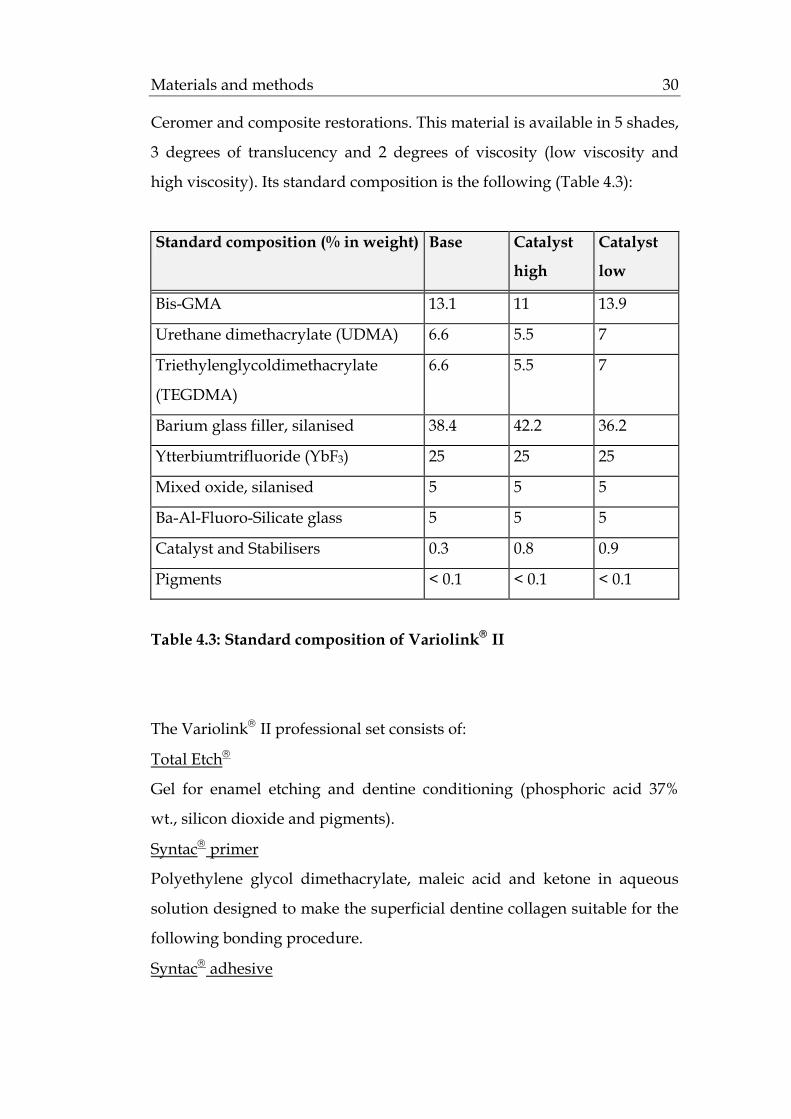
Ceromer and composite restorations. This material is available in 5 shades,
3 degrees of translucency and 2 degrees of viscosity (low viscosity and
high viscosity). Its standard composition is the following (Table 4.3):
Standard composition (% in weight) Base Catalyst
high
Catalyst
low
Bis-GMA 13.1 11 13.9
Urethane dimethacrylate (UDMA) 6.6 5.5 7
Triethylenglycoldimethacrylate
(TEGDMA)
6.6 5.5 7
Barium glass filler, silanised 38.4 42.2 36.2
Ytterbiumtrifluoride (YbF3) 25 25 25
Mixed oxide, silanised 5 5 5
Ba-Al-Fluoro-Silicate glass 5 5 5
Catalyst and Stabilisers 0.3 0.8 0.9
Pigments < 0.1 < 0.1 < 0.1
Table 4.3: Standard composition of Variolink® II
The Variolink® II professional set consists of:
Total Etch®
Gel for enamel etching and dentine conditioning (phosphoric acid 37%
wt., silicon dioxide and pigments).
Syntac® primer
Polyethylene glycol dimethacrylate, maleic acid and ketone in aqueous
solution designed to make the superficial dentine collagen suitable for the
following bonding procedure.
Syntac® adhesive

Materials and methods 31
Polyethylene glycol dimethacrylate and glutaraldehyde in an aqueous
solution.
Heliobond®
Light-curing single component bonding agent (Bis-GMA 60% wt. and
triethylene glycol dimethacrylate 40% wt.).
IPS Ceramic etching gel®
4.9% hydruofluoric acid, recommended for the EPC material.
Monobond-S®
Silane (99% wt. water/ethanol solution, acetic acid, 1% 3-
methacryloxypropyl-trimethoxysilane).
Liquid strip
Glycerine gel for the prevention of contact with oxygen.
4.1.4. Impression materials
Dimension® Garant L (3M-Espe, Seefeld, D): hydrophilic low consistency
addition polymerisation silicone material (polyvinyl-siloxane) with 99.9%
elastic return after deformation, -0.20% linear dimensional change after 24
hours and setting time of 5.30 minutes.
Permagum® Putty Soft (3M-Espe, Seefeld, D): high viscosity addition
silicone impression material with -0.05% linear dimensional change after
24 hours and setting time of 5 minutes.
4.1.5. Die materials
GC Fujirock® (GC Belgium): type 4 dental stone (water/powder ratio
20ml/100gr, setting expansion 0.08% and compressive strength 53 MPa).

Materials and methods 32
4.1.6. Additional materials used
The additional materials used are the following (Table 4.4):
Materials Company
Anti-Rutsch Lack Wenko-Wenselaar, GmbH Hilden,D
Technovit 4000 Heraus-Kulzer,Wehrheim, D
Diamonds No 386.023, No 8368.023,
No 7KR.012, No 8837KR.012
Gebr. Brasseler, Lemgo, D
Steatite ceramic balls Hoechst Ceram Tec, Wunsiedel, D
Thermocycling system Gebrüder Haake GmbH,Karlsruhe,D
Artificial oral environment Willytech, Munich, D
Table 4.4: Additional materials used in the study
4.2. Methods
4.2.1. Teeth
4.2.1.1. Selection of the abutment teeth
For this study 80 maxillary central incisors of comparable size were
selected and used as abutments. After the extraction they were stored in
0.1% thymol solution at room temperature (Sparrius and Grossman 1989).
Calculus deposits and soft tissue were removed using a hand scaler and
an ultra-scaler device where necessary.
Only teeth that had been visually examined and found to be sound and
free from caries, hypoplastic defects and cracks were included in this

Materials and methods 33
study. The teeth were randomly divided into five equal groups,
designated A, B, C, D and E. Each group contained 16 teeth.
4.2.1.2. Diagnostic Wax-up
An average-sized, completely healthy maxillary incisor, with a height of
11mm and width of 8.5 mm (Stambaugh and Wittrock 1977), was selected in
order to provide a reference for the preparation and the wax-up procedure
in the laboratory. The wax-up was modified to give the tooth an ideal
form for the final veneer restoration.
This model tooth was duplicated several times, using a silicone putty
matrix (Formasil®, Heraus-Kulzer, Wehrheim, D). A sagittal cut through
the impression offered the dentist and the dental technician the earlier
mentioned reference (Magne and Douglas 1999b). In this way a similarity of
design among the test groups was achieved.
4.2.1.3. Tooth preparation
In this study four different types of full veneer preparations were
compared. For this reason, the teeth were divided into the following five
groups:
• Group A = control group: natural teeth without preparation
• Group B = 1. test group: full veneer preparation maintained in the
enamel/ contact point on the natural tooth
• Group C = 2. test group: full veneer preparation maintained in the
enamel/ contact point on the veneer
• Group D = 3. test group: full veneer preparation extended into dentine/
contact point on the natural tooth
• Group E = 4. test group: full veneer preparation extended into dentine/
contact point on the veneer
Materials and methods 34
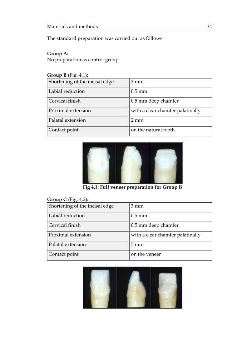
The standard preparation was carried out as follows:
Group A: No preparation as control group
Group B (Fig. 4.1): Shortening of the incisal edge 3 mm
Labial reduction 0.5 mm
Cervical finish 0.5 mm deep chamfer
Proximal extension with a clear chamfer palatinally
Palatal extension 2 mm
Contact point on the natural tooth.
Fig 4.1: Full veneer preparation for Group B
Group C (Fig. 4.2): Shortening of the incisal edge 3 mm
Labial reduction 0.5 mm
Cervical finish 0.5 mm deep chamfer
Proximal extension with a clear chamfer palatinally
Palatal extension 5 mm
Contact point on the veneer

Materials and methods 35
Fig 4.2: Full veneer preparation for Group C
Group D (Fig. 4.3):
Shortening of the incisal edge 3 mm
Labial reduction. 1 mm
Cervical finish 0.5 mm deep chamfer
Proximal extension with a clear chamfer palatinally
Palatal extension 2 mm
Contact point on the natural tooth
Fig 4.3: Full veneer preparation for Group D
Group E (Fig. 4.4):
Shortening of the incisal edge 3 mm
Labial reduction 1 mm
Cervical finish 0.5 mm deep chamfer
Proximal extension with a clear chamfer palatinally
Palatal extension 5 mm
Contact point on the veneer
Fig 4.4: Full veneer preparation for Group E

Materials and methods 36
4.2.2. Fabrication of the master models
4.2.2.1. Impression
After preparation, the abutment teeth were dried with air and cotton
pellets. Then, impressions of them were taken with a polyvinyl-siloxane
impression material (Dimension Garant L + Putty Soft, 3M-Espe, Seefeld,
D). For the impression procedure, perforated custom plastic trays were
used.
4.2.2.2. Fabrication of the master dies
One hour later, the impressions were sprayed with a surfactant and dried.
Distilled water and Fujirock® type 4 dental stone (GC, Tokyo, J) were
vacuum-mixed in a ratio of 20ml/100gr for 60 sec, and a cast of each
impression was poured. After the stone had set, the models were taken
out of the impressions and the prepared abutments were covered with a
thin flowing silicone (Prävegum; Pratzner, Böbingen, D) to protect the
margins from the trimming procedure. The models were trimmed, the
silicon films were removed and the preparation margins of the abutment
teeth were set free.
4.2.3. Fabrication of the veneers
All 64 veneers in groups B through E were fabricated out of EPC
VP2117/TC2 ceramic of the Fa. Ivoclar-Vivadent AG, Schaan, FL. The
following procedures were performed as recommended by the
manufacturer:
4.2.3.1. Wax-up
A sealer (Margidur, Benzer Dental AG, Zürich, CH) was applied on the
dies to harden the surface and to protect them without changing the

Materials and methods 37
dimensions. A layer of spacer (Purargent, Benzer Dental AG, Zürich, CH)
was applied up to 0.5 mm above the preparation margin.
A full wax-up was fabricated and a silicone index prepared. Organic
model dental wax that burns out without leaving residue was used for the
wax-up (Pro Art Sculpturing Wax, Williams, Ivoclar-Vivadent AG,
Schaan, FL).
4.2.3.2. Investment
A wax sprue with a round profile, 3-8 mm of length and 2-3 mm/8 gauge,
was attached directly to the wax-ups. The investment was mixed with its
liquid for 1 minute under vacuum, according to the manufacturer’s
instructions. After setting (1hour), the ring gauge and ring base were
removed. The paper ring and rough spots at the bottom of the investment
cylinder were also removed.
4.2.3.3. Preheat and Pressing
The investment cylinder was preheated in a conventional KaVo
preheating furnace, Type 5636. The following parameters were set:
-Temperature increase 5° C per minute
-Holding time 30 minutes at 250° C
-Final temperature 60 minutes at 850° C
For the pressing procedure of the ceramic veneers a special furnace (IPS
Empress® EP 500 hot press furnace, Ivoclar-Vivadent AG, Schaan, FL) was
used. The investment cylinder along with the ingot was placed at the
centre of the EP 500 press furnace and the pressing procedure followed.
The pressing temperature was 915°C. The exact pressing parameters were
set:
-Start temperature 700°C
-Temperature increase 60° C per minute

Materials and methods 38
-Final temperature at 915° C
-Holding time 20 minutes
-Vacuum start 500°C
-Vacuum stop 915°C
4.2.3.4. Divestment
After approximately 1 hour, the investment cylinder was removed from
the press furnace. Occasionally, the cylinders presented cracks due to
differences in the coefficients of thermal expansion of the various
materials. However, these cracks do not have to be considered as failures
of the pressing procedure.
The investment cylinder was separated, using a separating disc to create a
predetermined breaking point. The rough divestment was removed with
glazing blasting pearls at 2 bar pressure. The pressed veneers were cut
from the sprues and the attachment points were removed with
appropriate burs. Subsequently they were cleaned in Invex liquid (Ivoclar-
Vivadent AG, Schaan, FL) in an ultrasonic unit for 10 minutes, rinsed with
water and dried. Finally, they were carefully blasted with Al2O3 at 1 bar
pressure. The veneer fit was verified on the master models.
4.2.3.5. Glazing
The application of glazing and staining materials followed. Two glazing
procedures took place in Programat P100 with Empress® Universal Glasur
D64847. The firing parameters of these materials are reported as follows:
-Start temperature 403°C
-Temperature increase 60° C per minute
-Final temperature at 770° C
-Holding time 20 minutes
-Vacuum start 450°C
-Vacuum stop 769°C
Materials and methods 39
The fitting surfaces of the crowns were sandblasted with Al2O3 Type 100
at 1 bar pressure and cleaned with jet steam.
4.2.4. Cementation of the veneers
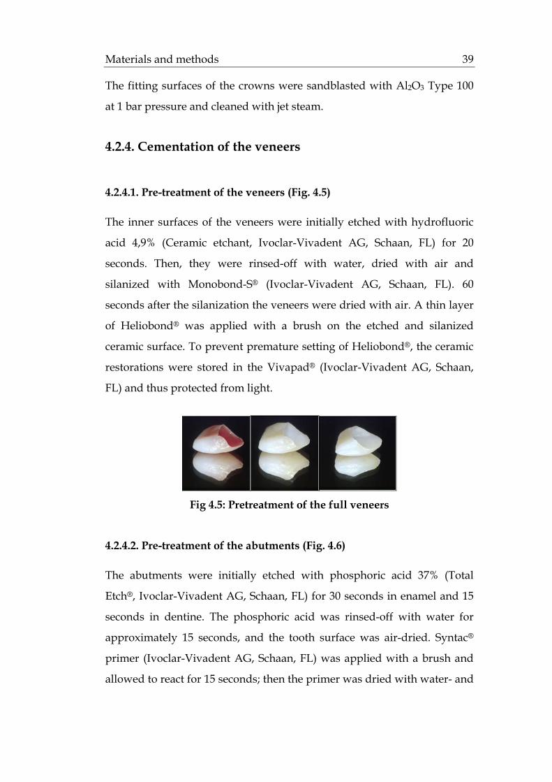
4.2.4.1. Pre-treatment of the veneers (Fig. 4.5)
The inner surfaces of the veneers were initially etched with hydrofluoric
acid 4,9% (Ceramic etchant, Ivoclar-Vivadent AG, Schaan, FL) for 20
seconds. Then, they were rinsed-off with water, dried with air and
silanized with Monobond-S® (Ivoclar-Vivadent AG, Schaan, FL). 60
seconds after the silanization the veneers were dried with air. A thin layer
of Heliobond® was applied with a brush on the etched and silanized
ceramic surface. To prevent premature setting of Heliobond®, the ceramic
restorations were stored in the Vivapad® (Ivoclar-Vivadent AG, Schaan,
FL) and thus protected from light.
Fig 4.5: Pretreatment of the full veneers
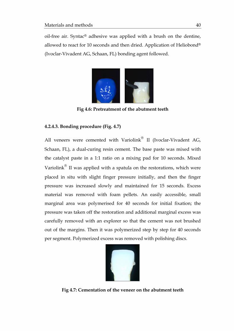
4.2.4.2. Pre-treatment of the abutments (Fig. 4.6)
The abutments were initially etched with phosphoric acid 37% (Total
Etch®, Ivoclar-Vivadent AG, Schaan, FL) for 30 seconds in enamel and 15
seconds in dentine. The phosphoric acid was rinsed-off with water for
approximately 15 seconds, and the tooth surface was air-dried. Syntac®
primer (Ivoclar-Vivadent AG, Schaan, FL) was applied with a brush and
allowed to react for 15 seconds; then the primer was dried with water- and
Materials and methods 40
oil-free air. Syntac® adhesive was applied with a brush on the dentine,
allowed to react for 10 seconds and then dried. Application of Heliobond®
(Ivoclar-Vivadent AG, Schaan, FL) bonding agent followed.
Fig 4.6: Pretreatment of the abutment teeth
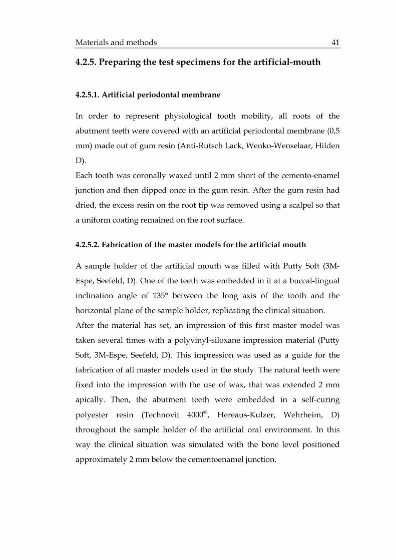
4.2.4.3. Bonding procedure (Fig. 4.7)
All veneers were cemented with Variolink® II (Ivoclar-Vivadent AG,
Schaan, FL), a dual-curing resin cement. The base paste was mixed with
the catalyst paste in a 1:1 ratio on a mixing pad for 10 seconds. Mixed
Variolink® II was applied with a spatula on the restorations, which were
placed in situ with slight finger pressure initially, and then the finger
pressure was increased slowly and maintained for 15 seconds. Excess
material was removed with foam pellets. An easily accessible, small
marginal area was polymerised for 40 seconds for initial fixation; the
pressure was taken off the restoration and additional marginal excess was
carefully removed with an explorer so that the cement was not brushed
out of the margins. Then it was polymerized step by step for 40 seconds
per segment. Polymerized excess was removed with polishing discs.
Fig 4.7: Cementation of the veneer on the abutment teeth
Materials and methods 41
4.2.5. Preparing the test specimens for the artificial-mouth
4.2.5.1. Artificial periodontal membrane
In order to represent physiological tooth mobility, all roots of the
abutment teeth were covered with an artificial periodontal membrane (0,5
mm) made out of gum resin (Anti-Rutsch Lack, Wenko-Wenselaar, Hilden
D).
Each tooth was coronally waxed until 2 mm short of the cemento-enamel
junction and then dipped once in the gum resin. After the gum resin had
dried, the excess resin on the root tip was removed using a scalpel so that
a uniform coating remained on the root surface.
4.2.5.2. Fabrication of the master models for the artificial mouth
A sample holder of the artificial mouth was filled with Putty Soft (3M-
Espe, Seefeld, D). One of the teeth was embedded in it at a buccal-lingual
inclination angle of 135° between the long axis of the tooth and the
horizontal plane of the sample holder, replicating the clinical situation.
After the material has set, an impression of this first master model was
taken several times with a polyvinyl-siloxane impression material (Putty
Soft, 3M-Espe, Seefeld, D). This impression was used as a guide for the
fabrication of all master models used in the study. The natural teeth were
fixed into the impression with the use of wax, that was extended 2 mm
apically. Then, the abutment teeth were embedded in a self-curing
polyester resin (Technovit 4000®, Hereaus-Kulzer, Wehrheim, D)
throughout the sample holder of the artificial oral environment. In this
way the clinical situation was simulated with the bone level positioned
approximately 2 mm below the cementoenamel junction.

Materials and methods 42
4.2.6. Dynamic loading in the artificial mouth
All specimens were artificially aged in a computer-controlled dual axis
chewing simulator (Willytec, Munich, D). The chewing simulator had
eight identical sample chambers and two stepper motors that allowed
computer-controlled vertical and horizontal movements between two
antagonistic specimens in each sample chamber (Fig. 4.8 and 4.9). The
masticatory load curve was programmed by combining this horizontal
(0.5 mm) and vertical (6 mm) motion. The computer unit controlled the
mechanical motion and the water flow of the cold and warm water baths
for the thermal cycling of the samples.
Each of the eight sample chambers had a plastic sample holder which was
adjusted and fixed with a butterfly nut to the base of the sample chamber
and the underlying lower crossbeam (Fig. 4.10). The samples were
embedded in resin into the lower sample holder. The lower crossbeam
was moved by one stepper motor and allowed a horizontal, sliding motion
of the samples.
Vertical guide rails were freely mounted within the bearings of the upper
crossbeam. The vertical height of the antagonistic, 6 mm in diameter,
steatite balls was adjusted by the adjustment screw on top of the upper
crossbeam (Fig. 4.10). Weights of 5 kg were mounted on top of the guide
rails and established a chewing force of 49 N. The upper crossbeam was
moved by the second stepper motor and moved the antagonistic steatite
balls vertically. Because the guide rails were freely mounted within
bearings in the crossbeam, their individual weight was fully transferred to
each lower sample. The effective impact force is dependent on the
antagonist’s total weight and on its velocity, and both could be precisely
controlled. The chewing machine’s computer unit calculates and displays
the effective impact as kinetic energy.

Materials and methods 43
Each sample chamber was equipped with a water nozzle through which
the sample was sprayed alternately with cold and warm water (Fig. 4.10).
To prevent the mixing of cold and warm water, the preceding water was
fully suctioned out before water of the other temperature was applied.
The cyclic dynamic occlusal load of 49 N was applied to the veneers for 1.2
million chewing cycles and 3.000 thermocyclings (5°/55°C) (Fig. 4.11). The
cycle frequency was set at 1.6 Hz. The following parameters were
assessed: rising speed: 55 mm/s; descending speed: 60 mm/s; forward
speed: 60 mm/s; backward speed: 55 mm/s (Table 4.5).
Chewing cycle 1.200.000
Cycle frequency 1.6 Hz
Vertical movement 7 mm
Horizontal movement 0.5 mm
Descending speed 60 mm/s
Rising speed 55 mm/s
Forward speed 60 mm/s
Backward speed 55 mm/s
0 point subincisal 2 mm
Applied weight pro sample 49N
Hot dwell time 60s
Hot bath temperature 55°C
Cold dwell time 60s
Cold bath temperature 5°C
Intermediate pause 12s
Table 4.5: Overview of the assessed parameters in the artificial mouth

Materials and methods 44
Fig 4.8: The dual-axis chewing simulator
1. upper crossbeam 6. pump for cold water removal
2. lower crossbeam 7. pump for warm water removal
3a. water reservoir in 8. pump for cold water application
3b. water reservoir out 9. pump for cold water application
4. filter for cold water 10. motor block
5. filter for warm water 11. table
Fig 4.9: Schematic drawing of the dual-axis chewing simulator with
eight sample chamber according to Kern et al. 1999

Materials and methods 45
vertical guide rail
adjustable weight
shock absorber ring
sample chamber base
adjustment screw
fixation ring
upper crossbeam
upper sample holder antagonistic sample sample lower sample holder
lower crossbeam
butterfly nut
water supply
water nozzle
sample chamber
water outlet
Fig 4.10: Schematic drawing of one chewing chamber according to Kern
et al. 1999
Fig 4.11: Test sample during dynamic loading

Materials and methods 46
4.7. Examination of post-bonding cracks
After dynamic loading in the artificial mouth, the samples that survived
were examined under the stereomicroscope (Zeiss, Jena, D) at a
magnification of 200x, in order to observe whether post-bonding crack
formation had occurred. The samples that failed were not examined
further.
4.8. Fracture strength test (Fig. 4.12)
All samples that survived the exposure to the artificial mouth were
statically loaded in the Zwick Z010/TN2S universal testing machine
(Zwick, Ulm, D), until fracture of the veneer or the tooth occurred.
Each sample was mounted in the test machine. A double layer of 1 mm tin
foil (DT Dental Tradint, Bad Kissingen, D) was placed in the incisal edge
of each veneer to ensure homogeneous stress distribution. The test started
via a computer connected to the testing machine. The 135° axially inclined
samples were subjected to an increasing compressive load with a speed of
1.5 mm/min until fracture occurred. The fracture strength and the
displacement were automatically recorded by the Text X-pert (Zwick,
Ulm, D) controlling the software of the machine. The recorded data was
automatically analysed, and a graph was drawn for each sample.
Fig. 4.12: Test sample loaded to fracture
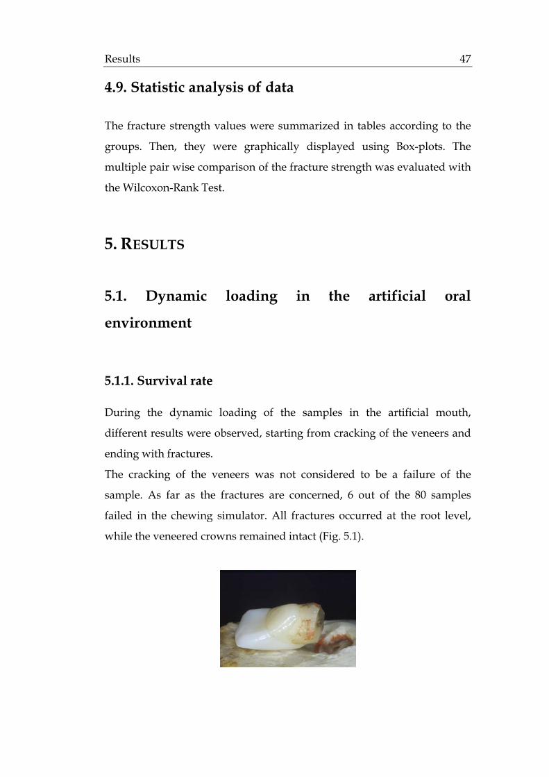
Results 47
4.9. Statistic analysis of data
The fracture strength values were summarized in tables according to the
groups. Then, they were graphically displayed using Box-plots. The
multiple pair wise comparison of the fracture strength was evaluated with
the Wilcoxon-Rank Test.
5. RESULTS
5.1. Dynamic loading in the artificial oral
environment
5.1.1. Survival rate
During the dynamic loading of the samples in the artificial mouth,
different results were observed, starting from cracking of the veneers and
ending with fractures.
The cracking of the veneers was not considered to be a failure of the
sample. As far as the fractures are concerned, 6 out of the 80 samples
failed in the chewing simulator. All fractures occurred at the root level,
while the veneered crowns remained intact (Fig. 5.1).

Results 48
Fig 5.1: Fracture of the test sample at the root level
The survival rate of the 5 groups was as follows (Fig. 5.2):
• Group A (no preparation)
In the control group, 3 out of the 16 samples fractured.
Sample no.6 fractured at 530.000 chewing cycles, sample no.8
fractured at 430.000 chewing cycles and sample no.14 fractured at
210.000 chewing cycles.
• Group B (preparation maintained in enamel/ contact point on the
tooth)
In test group B, all 16 samples survived the exposure to the artificial
environment.
• Group C (preparation maintained in enamel/ contact point on the
veneer)
In test group C, 2 out of the 16 samples fractured.
Sample no.5 fractured at 170.000 chewing cycles and sample no.10
fractured at 470.000 chewing cycles
• Group D (preparation extended into dentine / contact point on
the tooth)
In test group D, all 16 samples survived the exposure to the
artificial environment. • Group E (preparation extended into dentine / contact point on the
veneer)
In test group E, 1 out of the 16 samples fractured.
Sample no.7 fractured at 520.000 chewing cycles

Results 49
81%
100%
88%
100%94%
0%
10%
20%
30%
40%
50%
60%
70%
80%
90%
100%
Control group A Test group B Test group C Test group D Test group E
Control group A: no preparation
Test group B: preparation maintained in enamel / contact point on the tooth
Test group C: preparation maintained in enamel / contact point on the veneer
Test group D: preparation extended into dentin / contact point on the tooth
Test group E: preparation extended into dentin / contact point on the veneer
Fig. 5.2: The survival rate of the different groups

Results 50
5.1.2. Crack development
After dynamic loading in the artificial mouth, the samples that survived
were examined under the stereomicroscope (Zeiss, Jena, D) at a
magnification of 200x. The samples that failed were not examined further.
The rate and the position of the cracks were the topics of interest.
5.1.2.1. Crack formation rate (Fig. 5.3)
Among the different test groups, cracks in the porcelain veneers were
developed in 28 out of the 64 samples (44%). The crack formation rate was
as follows:
• Group B (preparation maintained in enamel/ contact point on the
tooth)
In test group B, cracks were observed in 3 out of the 16 samples.
• Group C (preparation maintained in enamel/ contact point on the
veneer)
In test group C, cracks were observed in 10 out of the 14 samples.
• Group D (preparation extended into dentin/ contact point on the
tooth)
In test group D, cracks were observed in 6 out of the 16 samples.
• Group E (preparation extended into dentin/ contact point on the
veneer)
In test group E, cracks were observed in 9 out of 15 samples.

Results 51
19%
71%
38%
60%
0%
10%
20%
30%
40%
50%
60%
70%
80%
90%
100%
Test group B Test group C Test group D Test group E
Test group B: preparation maintained in enamel / contact point on the tooth
Test group C: preparation maintained in enamel / contact point on the veneer
Test group D: preparation extended into dentin / contact point on the tooth
Test group E: preparation extended into dentin / contact point on the veneer
Fig. 5.3: The crack formation rate of porcelain veneers in the different test groups

Results 52
5.1.2.2. Crack pattern of porcelain veneers (Table 5.1)
Among the different test groups, differences were observed in the position
where the crack had developed. The crack pattern was as follows:
a. no crack
b. palatal (Fig. 5.4)
c. proximal (Fig. 5.5)
d. palatal and proximal (Fig. 5.6)
e. vestibular (Fig. 5.7)
f. circular, extended around the tooth
Fig 5.4: Cracks on the palatal Fig 5.5: Cracks on the prox.
surface of the veneer surface of the veneer
Fig 5.6: Cracks on the palatal and Fig 5.7: Cracks circumferentially
the prox. surface of the veneer on the veneer

Results 53
N no crack palat. prox. pal.+prox. vestib. circular
Group B 16 13 0 3 0 0 0
Group C 14 4 3 0 3 0 4
Group D 16 10 3 3 0 0 0
Group E 15 6 8 0 1 0 0
Table 5.1: Position on the porcelain veneers where the cracks were observed A statistical analysis of the above information is presented in Table 5.2. It
was of interest to compare if a higher crack formation rate occurred when
the contact point was on the veneer (groups C and E) instead of on the
tooth (groups B and D).
Group B and D Group C and E
No crack 23 10
Crack 9 19
Total 32 29*
*3 sampes fractured in the oral environment Table 5.2: Crack formation on the full veneers according to the contact point The pair-wise comparison was performed with the Fisher exact test. The
p-value was 0.005, which showed that there was a significant difference
between the groups.
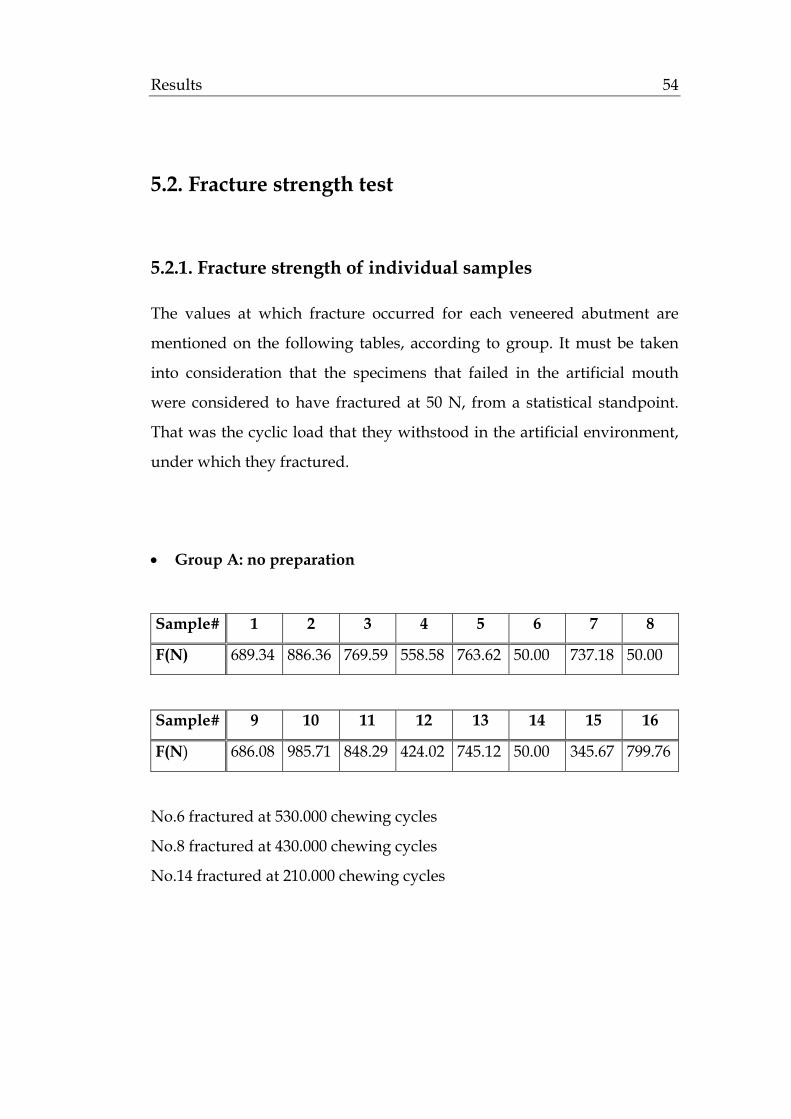
Results 54
5.2. Fracture strength test
5.2.1. Fracture strength of individual samples
The values at which fracture occurred for each veneered abutment are
mentioned on the following tables, according to group. It must be taken
into consideration that the specimens that failed in the artificial mouth
were considered to have fractured at 50 N, from a statistical standpoint.
That was the cyclic load that they withstood in the artificial environment,
under which they fractured.
• Group A: no preparation
Sample# 1 2 3 4 5 6 7 8
F(N) 689.34 886.36 769.59 558.58 763.62 50.00 737.18 50.00
Sample# 9 10 11 12 13 14 15 16
F(N) 686.08 985.71 848.29 424.02 745.12 50.00 345.67 799.76
No.6 fractured at 530.000 chewing cycles
No.8 fractured at 430.000 chewing cycles
No.14 fractured at 210.000 chewing cycles

Results 55
• Group B: preparation maintained in enamel/ contact point on the
tooth
Sample# 1 2 3 4 5 6 7 8
F(N) 848.78 643.78 848.48 649.55 661.73 669.87 816.69 589.26
Sample# 9 10 11 12 13 14 15 16
F(N) 489.77 414.14 644.57 463.51 861.17 698.07 268.72 221.98
• Group C: preparation maintained in enamel/ contact point on the
veneer
Sample# 1 2 3 4 5 6 7 8
F(N) 680.02 580.52 446.54 911.11 50.00 609.00 575.48 454.43
Sample# 9 10 11 12 13 14 15 16
F(N) 804.38 50.00 551.58 721.45 503.19 640.97 827.42 715.53
No.5 fractured at 170.000 chewing cycles
No.10 fractured at 470.000 chewing cycle
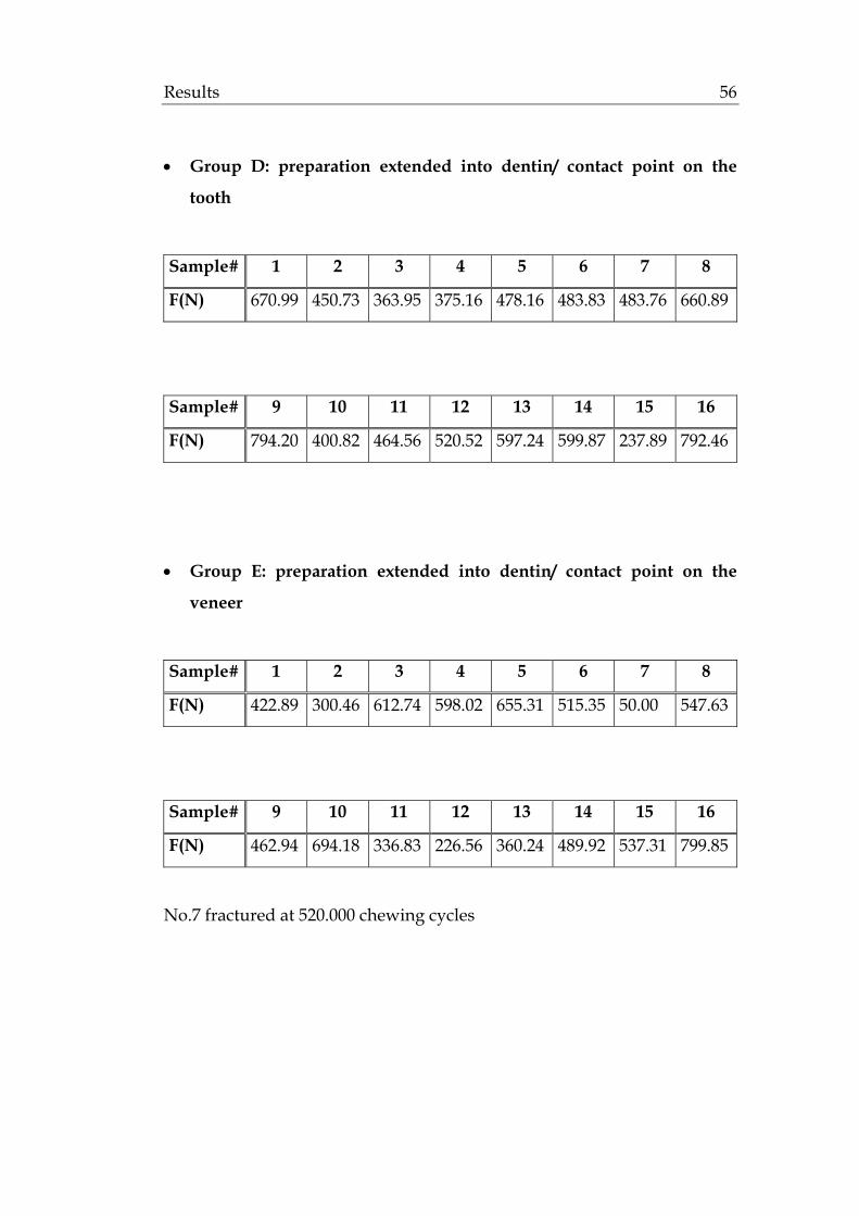
Results 56
• Group D: preparation extended into dentin/ contact point on the
tooth
Sample# 1 2 3 4 5 6 7 8
F(N) 670.99 450.73 363.95 375.16 478.16 483.83 483.76 660.89
Sample# 9 10 11 12 13 14 15 16
F(N) 794.20 400.82 464.56 520.52 597.24 599.87 237.89 792.46
• Group E: preparation extended into dentin/ contact point on the
veneer
Sample# 1 2 3 4 5 6 7 8
F(N) 422.89 300.46 612.74 598.02 655.31 515.35 50.00 547.63
Sample# 9 10 11 12 13 14 15 16
F(N) 462.94 694.18 336.83 226.56 360.24 489.92 537.31 799.85
No.7 fractured at 520.000 chewing cycles

Results 57
5.2.2. Statistical evaluation of data
The statistical analysis of the recorded fracture strength test results was
performed with a Boxplot representation of the median, quartiles,
minimum and maximum values (Table 5.3; Fig. 5.8).
Min. 1st
Quartile
Median Mean 3rd
Quartile
Max.
Control
group A
50.0 404.4 713.3 586.8 777.1 985.7
Test
group B
222.0 483.2 647.1 611.9 727.7 861.2
Test
group C
50.0 491.0 594.8 570.1 717.0 911.1
Test
group D
237.9 438.3 483.8 523.4 615.1 794.2
Test
group E
50.0 354.4 502.6 475.6 601.7 799.9
Table 5.3: Statistical analysis of the fracture strength test results in N

Results 58
a= Control group A: no preparation
b= Test group B: preparation maintained in enamel / contact point on the tooth
c= Test group C: preparation maintained in enamel / contact point on the veneer
d= Test group D: preparation extended into dentin / contact point on the tooth
e= Test group E: preparation extended into dentin / contact point on the veneer
Fig. 5.8: Box plot of the fracture strength test results in N
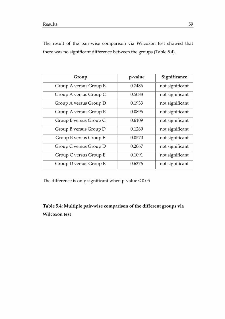
Results 59
The result of the pair-wise comparison via Wilcoxon test showed that
there was no significant difference between the groups (Table 5.4).
Group p-value Significance
Group A versus Group B 0.7486 not significant
Group A versus Group C 0.5088 not significant
Group A versus Group D 0.1933 not significant
Group A versus Group E 0.0896 not significant
Group B versus Group C 0.6109 not significant
Group B versus Group D 0.1269 not significant
Group B versus Group E 0.0570 not significant
Group C versus Group D 0.2067 not significant
Group C versus Group E 0.1091 not significant
Group D versus Group E 0.6376 not significant
The difference is only significant when p-value ≤ 0.05
Table 5.4: Multiple pair-wise comparison of the different groups via
Wilcoxon test

Results 60
5.2.3. Fracture patterns
Among the control and test groups, differences were observed in the
manner that the veneered abutments fractured. Several aspects were
examined. First of all, it was of interest to see which component failed
first, i.e the ceramic, the tooth, or both of them. Furthermore, it was
observed in which part of the restoration the fracture occurred.
5.2.3.1. Component of the restoration that failed
When the samples fractured, differences were observed concerning the
component that failed. Three possibilities were reported:
a. fracture of the ceramic (Fig. 5.9)
b. fracture of the tooth (Fig. 5.10)
c. fracture of the ceramic and the tooth (Fig. 5.11)
Fig 5.9: Fracture of the Fig 5.10: Fracture of the Fig 5.11: Fracture of the
ceramic tooth ceramic and tooth

Results 61
The results, according to group, were the following (Table 5.5):
N tooth tooth+ceramic ceramic
Group A 13 13 0 0
Group B 16 11 5 0
Group C 14 7 4 3
Group D 16 4 3 9
Group E 15 4 3 8
Table 5.5: Component of the restoration that failed
Based on the above table, a statistical analysis followed. It was of interest
to see if the thickness of the ceramic or the extension of dentine bonding
influenced the fracture of the full veneers. The thinner veneers in group B
and C were compared to the thicker ones in group D and E. It was
examined in which of the above cases the ceramic has resisted better to
fracture (Table 5.6).
intact ceramic fractured ceramic total
Group B and C 18 12 30*
Group D and E 8 23 31*
*3 samples fractured in the oral environment Table 5.6: Resistance of the ceramic to fracture according to thickness and extension of dentine bonding
The pair-wise comparison was performed with the Fisher exact test. The
p-value was 0.01, which showed that there was a significant difference
between the groups.
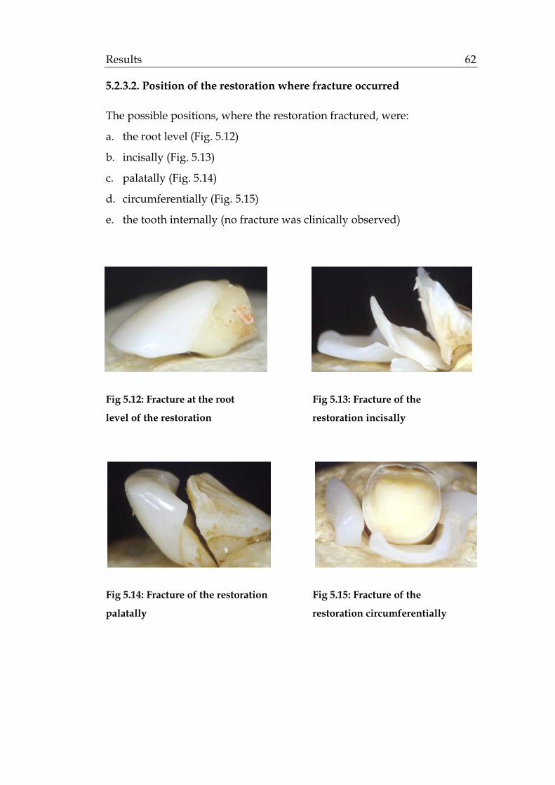
Results 62
5.2.3.2. Position of the restoration where fracture occurred
The possible positions, where the restoration fractured, were:
a. the root level (Fig. 5.12)
b. incisally (Fig. 5.13)
c. palatally (Fig. 5.14)
d. circumferentially (Fig. 5.15)
e. the tooth internally (no fracture was clinically observed)
Fig 5.12: Fracture at the root Fig 5.13: Fracture of the
level of the restoration restoration incisally
Fig 5.14: Fracture of the restoration Fig 5.15: Fracture of the
palatally restoration circumferentially
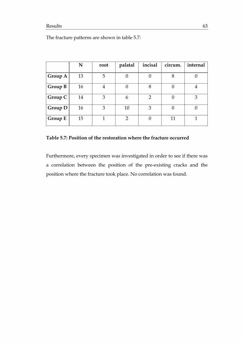
Results 63
The fracture patterns are shown in table 5.7:
N root palatal incisal circum. internal
Group A 13 5 0 0 8 0
Group B 16 4 0 8 0 4
Group C 14 3 6 2 0 3
Group D 16 3 10 3 0 0
Group E 15 1 2 0 11 1
Table 5.7: Position of the restoration where the fracture occurred
Furthermore, every specimen was investigated in order to see if there was
a correlation between the position of the pre-existing cracks and the
position where the fracture took place. No correlation was found.
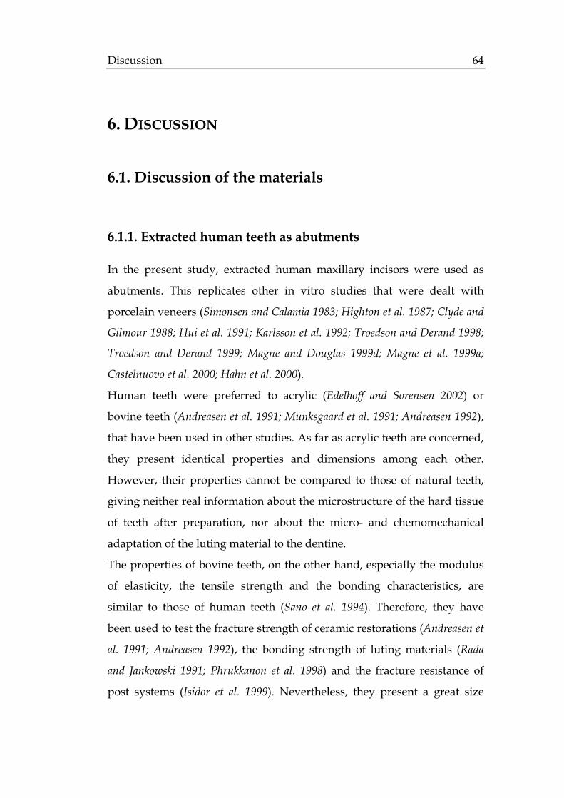
Discussion 64
6. DISCUSSION
6.1. Discussion of the materials
6.1.1. Extracted human teeth as abutments
In the present study, extracted human maxillary incisors were used as
abutments. This replicates other in vitro studies that were dealt with
porcelain veneers (Simonsen and Calamia 1983; Highton et al. 1987; Clyde and
Gilmour 1988; Hui et al. 1991; Karlsson et al. 1992; Troedson and Derand 1998;
Troedson and Derand 1999; Magne and Douglas 1999d; Magne et al. 1999a;
Castelnuovo et al. 2000; Hahn et al. 2000).
Human teeth were preferred to acrylic (Edelhoff and Sorensen 2002) or
bovine teeth (Andreasen et al. 1991; Munksgaard et al. 1991; Andreasen 1992),
that have been used in other studies. As far as acrylic teeth are concerned,
they present identical properties and dimensions among each other.
However, their properties cannot be compared to those of natural teeth,
giving neither real information about the microstructure of the hard tissue
of teeth after preparation, nor about the micro- and chemomechanical
adaptation of the luting material to the dentine.
The properties of bovine teeth, on the other hand, especially the modulus
of elasticity, the tensile strength and the bonding characteristics, are
similar to those of human teeth (Sano et al. 1994). Therefore, they have
been used to test the fracture strength of ceramic restorations (Andreasen et
al. 1991; Andreasen 1992), the bonding strength of luting materials (Rada
and Jankowski 1991; Phrukkanon et al. 1998) and the fracture resistance of
post systems (Isidor et al. 1999). Nevertheless, they present a great size

Discussion 65
discrepancy in comparison to human teeth, and consequently a difficulty
in the fabrication of the ceramic restoration.
In the case of human extracted teeth, the advantage is that they possess
similar modulus of elasticity, hardness, strength and bonding
characteristics as the teeth in the oral environment. A disadvantage is that
there is a great variation in age, size, shape and quality, making it difficult
to standardize the samples (Morgano and Milot 1993; Isidor et al. 1999). In
order to minimize this danger, an attempt was made to select abutments
with comparable sizes. For that purpose a silicone control key of an
average-sized incisor was used. The extracted human teeth that were too
big or too small, as well as teeth with caries were excluded.
6.1.2. The storage solution
In the present study the extracted teeth were stored in thymol solution.
Other authors have reported the use of distilled water (Andreasen et al.
1991; Andreasen 1992; Reeh and Ross 1994; Castelnuovo et al. 2000), NaCl
(Stacey 1993; Magne et al. 1999a), or 10% formol solution (Stokes and Hood
1993).
A thymol solution of 0.1 % concentration was used in this study to prevent
the specimens from drying out and thereby becoming brittle. The thymol
solution also functioned as an antibacterial means of storage (Sparrius and
Grossman 1989).
6.1.3. EPC as a material for the fabrication of full veneers
In this study an EPC from Ivoclar-Vivadent AG (Schaan, FL) was used for
the fabrication of the full veneers. According to manufacturer it is
considered to have a higher flexural strength (525 Mpa) in comparison to
sintered ceramics. It seems to combinate a higher fracture than Empress I®
(Ivoclar-Vivadent AG, Schaan, FL) and a higher translucency than

Discussion 66
Empress II® (Ivoclar-Vivadent AG, Schaan, FL), similar to the natural
tooth. According to Isenberg et al. (1992) veneers fabricated with such a
pressable ceramic have also a better marginal adaptation compared to the
CAD/CAM or copy milling system.
6.2. Discussion of the methods
6.2.1. Preparation of the specimens for the artificial mouth
6.2.1.1. Preparation
It remains controversial whether different tooth preparation designs can
affect the strength of ceramic veneers, or whether one configuration of
tooth is superior to another. Highton et al. (1987) claimed that preparation
with incisal overlap contributed to a better distribution of load forces and
was consequently less prone to fracture.
Gilde et al. (1989), Hui et al. (1991), Hahn et al. (2000), however, reported
that porcelain veneers without overlap demonstrated more resistance to
load, when compared to overlapping veneers.
Wall et al. (1992b) and Meijering et al. (1997), furthermore, were unable to
distinguish any difference in failure rate between incisal preparation
designs.
However an overlapping veneer preparation is necessary when aesthetics
on the incisal edge third or occlusal corrections demand it (Dumfahrt 2000).
Castelnuovo et al. (2000) showed that if the reduction of incisal edge is
considered necessary then a bevel preparation is preferred than an incisal
overlap.
In this study, the preparation forms that were examined can be used as
restorative options in more severe defects. When a tooth fracture is located
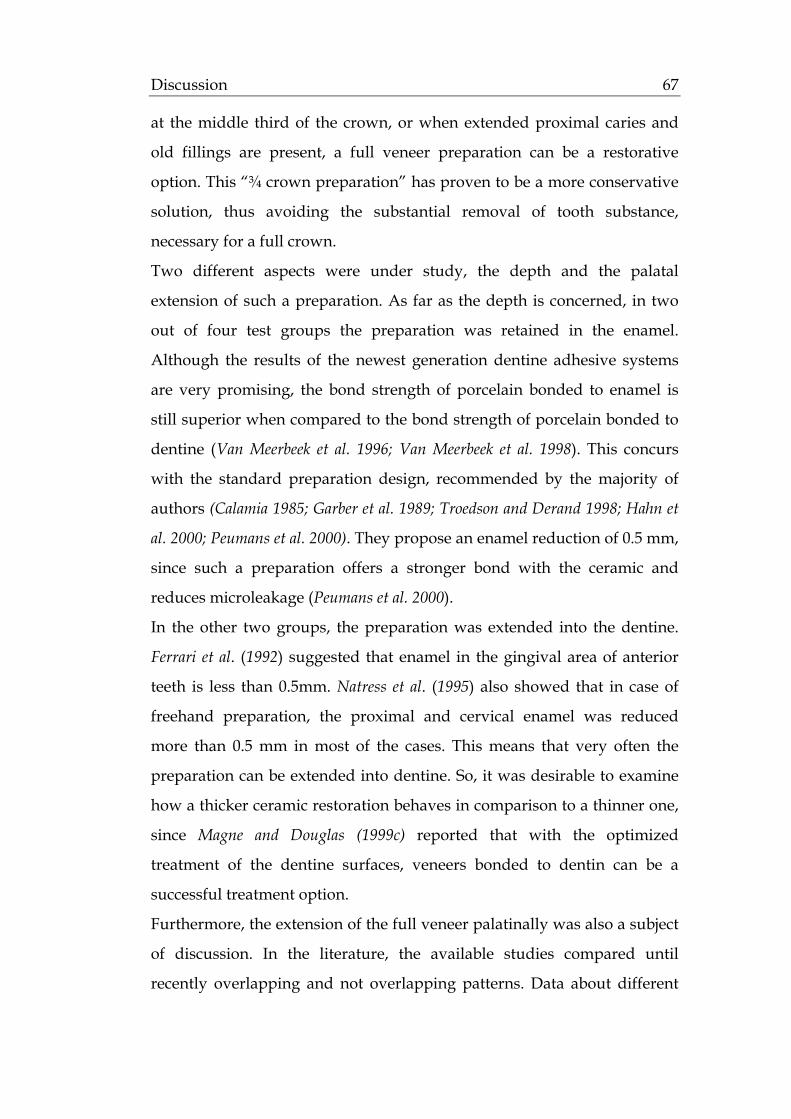
Discussion 67
at the middle third of the crown, or when extended proximal caries and
old fillings are present, a full veneer preparation can be a restorative
option. This “¾ crown preparation” has proven to be a more conservative
solution, thus avoiding the substantial removal of tooth substance,
necessary for a full crown.
Two different aspects were under study, the depth and the palatal
extension of such a preparation. As far as the depth is concerned, in two
out of four test groups the preparation was retained in the enamel.
Although the results of the newest generation dentine adhesive systems
are very promising, the bond strength of porcelain bonded to enamel is
still superior when compared to the bond strength of porcelain bonded to
dentine (Van Meerbeek et al. 1996; Van Meerbeek et al. 1998). This concurs
with the standard preparation design, recommended by the majority of
authors (Calamia 1985; Garber et al. 1989; Troedson and Derand 1998; Hahn et
al. 2000; Peumans et al. 2000). They propose an enamel reduction of 0.5 mm,
since such a preparation offers a stronger bond with the ceramic and
reduces microleakage (Peumans et al. 2000).
In the other two groups, the preparation was extended into the dentine.
Ferrari et al. (1992) suggested that enamel in the gingival area of anterior
teeth is less than 0.5mm. Natress et al. (1995) also showed that in case of
freehand preparation, the proximal and cervical enamel was reduced
more than 0.5 mm in most of the cases. This means that very often the
preparation can be extended into dentine. So, it was desirable to examine
how a thicker ceramic restoration behaves in comparison to a thinner one,
since Magne and Douglas (1999c) reported that with the optimized
treatment of the dentine surfaces, veneers bonded to dentin can be a
successful treatment option.
Furthermore, the extension of the full veneer palatinally was also a subject
of discussion. In the literature, the available studies compared until
recently overlapping and not overlapping patterns. Data about different

Discussion 68
preparation designs palatinally is limited. Magne and Douglas (1999a)
reported in a finite-element study that extensive chamfering into the
palatal concavity must be avoided, due to the accumulation of functional
stresses in this area, and recommended a short chamfer or bevel.
Castelnuovo et al. (2000) also reported the palatal chamfer appeared to be
the weak feature that displayed cracks extending to the facial surface of
the veneer. In our study, instead of a short chamfer, a short bevel was
created to examine if a thicker preparation and consequent ceramic
restoration at the palatinal margin represented a favourable feature in the
prevention of palatinal cracks and provided a better stress distribution.
6.2.1.2. Cementation
Since ceramics have a lower flexural strength, it is the bond to the
underlying tooth structure that provides the full veneers the strength
necessary to resist the incisal shear loads and survive intraorally.
In the present study, the ceramic surface was etched (IPS Ceramic etching
gel®, Ivoclar-Vivadent AG, Schaan, FL) and silanated (Monobond-S®,
Ivoclar-Vivadent, Schaan, FL) as the majority of authors reported
(Simonsen and Calamia 1983; Calamia 1985; Friedman 1998; Hahn et al. 2000).
Malament and Socransky (1999) reported the importance of acid etching for
the survival of Dicor glass-ceramic restorations. Nonacid-etched
restorations had a 2.2 times greater risk of failure compared to the acid-
etched ones. Calamia and Simonsen (1983) also showed that silane coupling
agents improved the bond strength to a resin composite-based luting
material by about 20%.
For the conditioning of the tooth surface, a total etch system (Total Etch®,
Vivadent-Ivoclar AG, Schaan, FL) for both enamel and dentin was
preferred. As mentioned, in half of the specimens the preparation was
extended into dentine. In the other half, where the preparation was
maintained in the enamel, there was always a suspicion of dentine
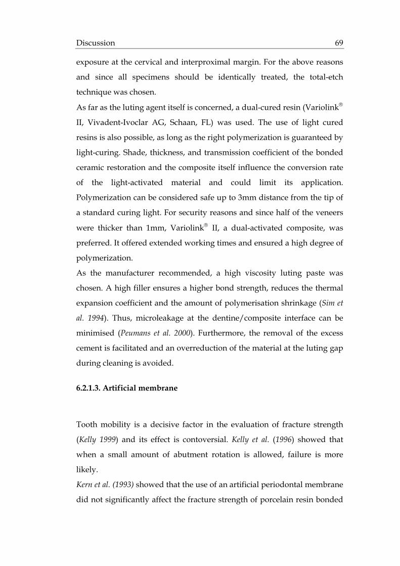
Discussion 69
exposure at the cervical and interproximal margin. For the above reasons
and since all specimens should be identically treated, the total-etch
technique was chosen.
As far as the luting agent itself is concerned, a dual-cured resin (Variolink®
II, Vivadent-Ivoclar AG, Schaan, FL) was used. The use of light cured
resins is also possible, as long as the right polymerization is guaranteed by
light-curing. Shade, thickness, and transmission coefficient of the bonded
ceramic restoration and the composite itself influence the conversion rate
of the light-activated material and could limit its application.
Polymerization can be considered safe up to 3mm distance from the tip of
a standard curing light. For security reasons and since half of the veneers
were thicker than 1mm, Variolink® II, a dual-activated composite, was
preferred. It offered extended working times and ensured a high degree of
polymerization.
As the manufacturer recommended, a high viscosity luting paste was
chosen. A high filler ensures a higher bond strength, reduces the thermal
expansion coefficient and the amount of polymerisation shrinkage (Sim et
al. 1994). Thus, microleakage at the dentine/composite interface can be
minimised (Peumans et al. 2000). Furthermore, the removal of the excess
cement is facilitated and an overreduction of the material at the luting gap
during cleaning is avoided.
6.2.1.3. Artificial membrane
Tooth mobility is a decisive factor in the evaluation of fracture strength
(Kelly 1999) and its effect is contoversial. Kelly et al. (1996) showed that
when a small amount of abutment rotation is allowed, failure is more
likely.
Kern et al. (1993) showed that the use of an artificial periodontal membrane
did not significantly affect the fracture strength of porcelain resin bonded

Discussion 70
bridges in comparison to abutments which were directly embedded in
acrylic material.
Kappert and Knode (1990) tested the fracture strength of 3-unit bridges on
metal dies. They used elastic rings and silicone material around the teeth
in half of the samples to simulate physiological tooth mobility. They
reported a mean fracture strength of 703 N for the group with
physiological tooth mobility in comparison to 225 N for the group with no
abutment mobility.
Furthermore, the materials used in order to achieve the tooth mobility
vary in the literature. In some studies, samples were embedded directly
into the resin (Beschnidt and Strub 1999), when the periodontal movement
was already foreseen in the chewing simulator. Other authors have
embedded their samples in thiokol resin (Stokes and Hood 1993), in nylon
rings and orthodontic resin (Reeh and Ross 1994), or in phenol rings and
epoxy resin (Castelnuovo et al. 2000). In the present study, the simulation of
the physiological tooth movement was desirable, in an attempt to
resemble the clinical situation. For this reason, a thin 0,5 mm layer of gum
resin (Anti-Rutsch-Lack®, Wenko-Wenselaar, GmbH Hilden, D) was
applied on the root of the incisors, up to 2 mm below the cementoenamel
junction. This simulated the position of the alveolar bone with regard to
the biological width (Gargiulo 1961; Kois 1994). Kern et al. (1993) showed
that this method could imitate the tooth mobility during dynamic loading
and fracture strength testing.
6.2.2. Dynamic loading in the artificial mouth
6.2.2.1. Angulation in the artificial mouth
Load angulation can represent a crucial factor when testing the strength of
the teeth. In some studies that compared fracture strength of different

Discussion 71
designs for ceramic veneers, the specimens were tested by loading the
veneer-tooth system directly at the incisal edge and in a direction parallel
to the long axis of the tooth (Highton et al. 1987; Hui et al. 1991).
Nevertheless, the orthognathic interincisal angle in case of natural
dentition is 135° (Reitz 1973). Stresses that affect maxillary ceramic veneers
during mastication and protrusive mandibular movements are not usually
directed parallel to the long axis of a tooth. Elevated loads generated
during parafunction are not applied in this direction either. Such loads are
usually directed toward the palatal surface of maxillary incisors and are
not parallel to the long axis of the tooth (Castelnuovo et al. 2000).
For the above reasons, in the present study the veneered abutments were
fixed in the specimen holder at a 135° angle to the saggital plane and 2° to
the vertical plane. This concurs with other studies (Castelnuovo et al. 2000;
Hahn et al. 2000), that also tried to simulate the clinical situation.
6.2.2.2. Contact point of the applied force in the artificial mouth
In the present study, the force was applied palatinally on the veneered
abutment, 6 mm apical to the incisal edge. Thus, an attempt was made to
reproduce the clinical situation, since the points of application of the forces
during occlusion on maxillary anterior teeth are predominantly within a
range of 2-6 mm from the incisal edge (Coca and Schwickerath 1987).
6.2.2.3. Artificial ageing and its clinical relevance on the survival rate of
ceramic veneers
In order to consider a dental material or design acceptable for clinical use,
5-year clinical results should be available (Strub 1992). However, clinical
studies are time consuming, expensive and, additionally, it is often
difficult to standardize the test parameters (Kern et al. 1999). Therefore,
various in vitro tests have been developed to simulate clinical conditions
and to save evaluation time (Krejci et al. 1994; Kern et al. 1999).
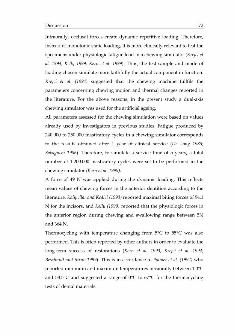
Discussion 72
Intraorally, occlusal forces create dynamic repetitive loading. Therefore,
instead of monotonic static loading, it is more clinically relevant to test the
specimens under physiologic fatigue load in a chewing simulator (Krejci et
al. 1994; Kelly 1999; Kern et al. 1999). Thus, the test sample and mode of
loading chosen simulate more faithfully the actual component in function.
Krejci et al. (1994) suggested that the chewing machine fullfils the
parameters concerning chewing motion and thermal changes reported in
the literature. For the above reasons, in the present study a dual-axis
chewing simulator was used for the artificial ageing.
All parameters assessed for the chewing simulation were based on values
already used by investigators in previous studies. Fatigue produced by
240.000 to 250.000 masticatory cycles in a chewing simulator corresponds
to the results obtained after 1 year of clinical service (De Long 1985;
Sakaguchi 1986). Therefore, to simulate a service time of 5 years, a total
number of 1.200.000 masticatory cycles were set to be performed in the
chewing simulator (Kern et al. 1999).
A force of 49 N was applied during the dynamic loading. This reflects
mean values of chewing forces in the anterior dentition according to the
literature. Kalipcilar and Kedici (1993) reported maximal biting forces of 94.1
N for the incisors, and Kelly (1999) reported that the physiologic forces in
the anterior region during chewing and swallowing range between 5N
and 364 N.
Thermocycling with temperature changing from 5°C to 55°C was also
performed. This is often reported by other authors in order to evaluate the
long-term success of restorations (Kern et al. 1993; Krejci et al. 1994;
Beschnidt and Strub 1999). This is in accordance to Palmer et al. (1992) who
reported minimum and maximum temperatures intraorally between 1.0°C
and 58.5°C and suggested a range of 0°C to 67°C for the thermocycling
tests of dental materials.

Discussion 73
6.2.3. Load-to-fracture testing
6.2.3.1. Angulation in the Zwick testing machine
In the present study, the specimens were tested in the Zwick universal
testing machine, until fracture occurred. They were set at an angle of 135°
to their long axis, like in the artificial mouth. The angulation is in
agreement with the intraoral orthognathic interincisal angle of 135°, as
mentioned before (Reitz 1973).
In the literature, however, other angulations have also been used. Highton
et al. (1987) loaded specimens at an angle of 0° to the tooth long axis.
Castelnuovo et al. (2000) loaded specimens at an angle of 90°. Troedson and
Derand (1999) loaded specimens at an angle of 0°, 30°, 60° to the tooth long
axis and reported higher values in the case of 0°.
Nevertheless, Hahn et al. (2000) tested an angle of 135°, that similar to our
study was considered to be the one closer to the clinical situation.
6.2.3.2. Contact point of the load-to-fracture applied force
In our study, the veneers were loaded until fracture on their incisal edge
(Hölsch 1992). This is comparable with other studies, like Highton et al.
(1987), Gilde et al. (1989), Hui et al. (1991), and Troedson and Derand (1999),
who loaded specimens to fracture directly on the incisal edge.
However, Castelnuovo et al. (2000) loaded 2,5 mm apical to the incisal edge.
Andreasen et al. (1992) and Stokes and Hood (1993), on the other hand,
loaded specimens vestibularly.
In the clinical situation, the occlusal forces are applied approximately 3
mm apical to the incisal edge (Coca and Schwickerath 1987). However, our
study required the total force to be applied on the veneer, which is the
weakest feature in our restoration design. If a palatinal loading pattern
was to be chosen, then the tooth surface would have been loaded in half of

Discussion 74
our specimens (in the groups were the contact point was on the natural
tooth). This could have lead to a failure of the tooth first and not of the
veneer. This was not the purpose of our test.
Furthermore, a double layer of 1mm tin foil was placed on the incisal edge
of each veneer. The goal was to avoid a loading on one point only and to
ensure a homogeneous stress distribution (Hölsch 1992).
6.2.3.3. Clinical relevance of the fracture strength tests of ceramic
veneers
Fracture strength tests of ceramic restorations are of substantial
importance in deciding the efficiency, longevity and subsequent success of
the reconstructions. Ideally, in vitro load-to-failure tests should simulate
clinical failure, in order to evaluate new materials or designs and
recommend them for clinical use.
Kelly (1999) questioned the clinical validity of the such tests. He suggested
that significant differences were found between the failure behaviour
created during traditional load to failure tests and that observed to have
occurred during clinical failure of all ceramic restorations. Examination of
clinically filed glass-ceramic restorations revealed that failures initiated
from flaws and stresses existing at the cementation surface. In contrast, in
vitro tests induce failure from damage at the occlusion surface.
Another problem of laboratory testing is that extremely high loads are
required compared with those during mastication, swallowing or
clenching movements. He concluded that traditional laboratory tests fail
to (1) create appropriate stress states, (2) cause failure from clinically
relevant flaws, or (3) create crack systems modelled on clinical failure.
For the above reasons, several sections found in the dental literature
regarding the strength and function of ceramic veneers could be
misleading. More realistic conditions must be produced, so that the
clinical situation can be reproduced more closely.
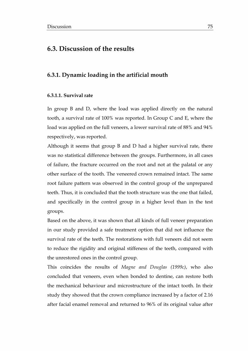
Discussion 75
6.3. Discussion of the results
6.3.1. Dynamic loading in the artificial mouth
6.3.1.1. Survival rate
In group B and D, where the load was applied directly on the natural
tooth, a survival rate of 100% was reported. In Group C and E, where the
load was applied on the full veneers, a lower survival rate of 88% and 94%
respectively, was reported.
Although it seems that group B and D had a higher survival rate, there
was no statistical difference between the groups. Furthermore, in all cases
of failure, the fracture occurred on the root and not at the palatal or any
other surface of the tooth. The veneered crown remained intact. The same
root failure pattern was observed in the control group of the unprepared
teeth. Thus, it is concluded that the tooth structure was the one that failed,
and specifically in the control group in a higher level than in the test
groups.
Based on the above, it was shown that all kinds of full veneer preparation
in our study provided a safe treatment option that did not influence the
survival rate of the teeth. The restorations with full veneers did not seem
to reduce the rigidity and original stiffeness of the teeth, compared with
the unrestored ones in the control group.
This coincides the results of Magne and Douglas (1999c), who also
concluded that veneers, even when bonded to dentine, can restore both
the mechanical behaviour and microstructure of the intact tooth. In their
study they showed that the crown compliance increased by a factor of 2.16
after facial enamel removal and returned to 96% of its original value after

Discussion 76
the placement of the veneer. Similar results were found in the study of
Magne and Douglas (2000a), who reported no significant differences in
crown flexure between natural and veneered incisors. Even when
composite build-ups were used to replace the missing dentine in cases of
fracture defects, the original tooth compliance was almost restored (Magne
and Douglas 1999d).
6.3.1.2. Crack formation
After the dynamic loading in the artificial mouth, the full veneers were
examined under the stereomicroscope. Crack formation was observed at
64% of the samples.
The rate of the existing cracks was higher in groups C (69%) and E (56%),
where the antagonist was coming in contact with the full veneer. In
groups B and D, on the other hand, where the antagonist was coming in
contact with the natural tooth, the reported rate was lower (19% and 38%
respectively). The statistical analysis showed a significant difference
between the two categories.
Based on the above results, it can be concluded that the extension of full
veneers palatally plays a preliminary role in crack formation. And since
this crack formation is a possible consequence of polymerization
shrinkage, function and thermocycling (Magne et al. 1999a), these are the
parameters that have to be relatively examined.
Initially, thermocycling have the same influence in all groups and can be
thus excluded as a reason that caused the above results. On the other
hand, function seems to be decisive. When the antagonist is coming in
contact with porcelain, numerous cracks are developed. According to the
literature, the level of the fossa happens to be the area of maximum tensile
stress (Magne et al. 1999a). Because of the ceramic brittleness, these tensile
forces are the most detrimental for the restoration during mechanical
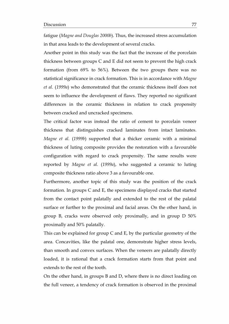
Discussion 77
fatigue (Magne and Douglas 2000b). Thus, the increased stress accumulation
in that area leads to the development of several cracks.
Another point in this study was the fact that the increase of the porcelain
thickness between groups C and E did not seem to prevent the high crack
formation (from 69% to 56%). Between the two groups there was no
statistical significance in crack formation. This is in accordance with Magne
et al. (1999a) who demonstrated that the ceramic thickness itself does not
seem to influence the development of flaws. They reported no significant
differences in the ceramic thickness in relation to crack propensity
between cracked and uncracked specimens.
The critical factor was instead the ratio of cement to porcelain veneer
thickness that distinguishes cracked laminates from intact laminates.
Magne et al. (1999b) supported that a thicker ceramic with a minimal
thickness of luting composite provides the restoration with a favourable
configuration with regard to crack propensity. The same results were
reported by Magne et al. (1999a), who suggested a ceramic to luting
composite thickness ratio above 3 as a favourable one.
Furthermore, another topic of this study was the position of the crack
formation. In groups C and E, the specimens displayed cracks that started
from the contact point palatally and extended to the rest of the palatal
surface or further to the proximal and facial areas. On the other hand, in
group B, cracks were observed only proximally, and in group D 50%
proximally and 50% palatally.
This can be explained for group C and E, by the particular geometry of the
area. Concavities, like the palatal one, demonstrate higher stress levels,
than smooth and convex surfaces. When the veneers are palatally directly
loaded, it is rational that a crack formation starts from that point and
extends to the rest of the tooth.
On the other hand, in groups B and D, where there is no direct loading on
the full veneer, a tendency of crack formation is observed in the proximal
Discussion 78
surface rather than in the palatal. In the literature, there is no available
data explaining the above phenomenon. A speculation could be that
ceramic is slightly thinner in the proximal aspect than in the neighbouring
palatal or incisal aspect, making thus the veneer there prone to cracking.
6.3.2. Load-to-fracture testing
6.3.2.1. Fracture strength of the specimens in the Zwick universal
machine
The specimens that fractured in the artificial mouth could not be tested in
the universal testing machine. From a statistical standpoint they were
considered to have fractured at 50 N, since that was the cyclic load that
they withstood in the artificial environment, under which they fractured.
The full veneers in Group B and C, that were bonded to enamel, presented
mean fracture strength values of 611.88 N and 570.1 N consequently. The
full veneers in Group D and E, that were bonded to dentin, presented
mean fracture strength values of 523.41 N and 475.6 N consequently.
All the above mean fracture strength values were within the limits of
clinical acceptance when compared with the physiologic forces developed
in-vitro. According to the literature, Helkimo et al. (1977) reported average
values of 137 N for the incisors. Sonnenburg et al. (1978) found that the
average load values for anterior teeth are between 215 N and 360 N for
men and 115 N and 269 N for women and Kalipcilar and Kedici (1993)
reported maximal biting forces of 94.1 N for the incisors. Kelly (1999)
reported that the physiologic forces in the anterior region during chewing
and swallowing range between 5 N and 364 N, and the maximum forces
during clenching between 216 N and 890 N.
The question whether the bonding of veneers to enamel, in comparison to
dentine, would provided higher values of fracture strength was negatively

Discussion 79
answered by these results. Among the groups, the differences were not
found to be statistically significant.
In-vitro, there is limited data comparing the fracture strength of veneers
bonded to these two different surfaces. The studies of Castelnuovo et al.
(2000) and Hahn et al. (2000) compared different preparation designs
within the enamel. They report values between 164-310 N for maxillary
incisor and 466-653 N for mandibular incisors respectively. The great
difference between the values is the support provided by the jaw and
varying angle of loading. Castelnuovo et al. (2000) loaded speciments at an
angle of 90° to the tooth long axis, whereas Hahn et al. (2000) loaded
speciments incisally as in this study. That is why the last results can be
comparable to the ones in our study, concerning only groups B and D,
where the preparation remained in the enamel.
On the other hand, Magne and Douglas (1999c) and Magne and Douglas
(2000a) experimented with dentine-bonded porcelain veneers in relation to
crown flexure and stiffness, but they did not study their fracture resistance
compared to strength. In-vivo Dumfahrt (2000) reported that in 6 out of 7
cases, the failures were located at the restoration-dentine interface,
supporting the suggestion of Christensen and Christensen (1991) that the
connection of resin cement to dentine may be the weakest link in bonding
porcelain veneers. To this weak link are also attributed the lower fracture
values in groups D and E.
6.3.2.2. Fracture pattern of the specimens in the Zwick universal
machine
After the load-to-fracture testing, three failure patterns were observed. In
some cases it was the tooth that fractured, in some others the ceramic, or a
third possibility was that both the tooth and the ceramic broke.
Discussion 80
It was of interest to see whether the thickness of the ceramic influenced the
resistance of the material to fracture. In groups B and C, where thin
ceramic veneers were bonded to enamel, 18 out of the 30 ceramic samples
remained intact and it was the tooth that broke.
Another scenario was often recorded in group D and E, where thicker
ceramic veneers were bonded to dentine. In 23 out of the 31 specimens, a
fracture was observed on the ceramic. In some of the above cases (6) the
tooth broke at the same time, but in most of them (17) only the veneers
fractured and not the tooth.
The above results were statistically analyzed and a significant difference
was found between the two groups. Thinner veneers remained intact more
often after fracture in comparison to thicker ones. In concurrence with
extensive literature on the subject, it is proven that the resistance of a
ceramic restoration depends not on the thickness of the ceramic, but on the
strength of the adhesion complex. Characteristically, Stacey (1993) reported
that the strength of the complex porcelain/luting composite/enamel (63
MPa) was almost double than that of the separate composite/etched
enamel (31 MPa) and the separate luting composite/porcelain (33MPa)
bond strengths. Andreasen et al. (1991) and Stokes and Hood (1993) proved
also that extracted incisors restored with porcelain veneers recovered to
their original strength.
In groups B and C, where the thinner ceramic was luted on enamel, the
composite/etched enamel bonding was so strong that it resisted the
transmitted stresses and the tooth structure failed first. On the contrary,
although thicker, the veneers that were bonded to dentine fractured in
most of the cases first, leaving the tooth intact. This can be also explained
by the fact that the link in bonding porcelain veneers is the weakest at the
restoration-dentine interface (Christensen and Christensen 1991).

Discussion 81
Initially, it seems that thinner veneers behaved better in our in-vitro study.
But it has to be taken into consideration that clinically a full veneer
restoration is a treatment option in cases of more extended defects, where
less enamel is left. Thus, it is clinically important that in case of the dentin
bonded veneers, if a failure is to happen, it is more likely that the ceramic
will fail, protecting the tooth structure.
7. CONCLUSIONS
The following conclusions can be drawn from this study:
(a) Full veneers are indicated in clinical practice, since all mean fracture
strength values obtained were within the limits of clinical acceptance.
Thus, the removal of large amounts of sound tooth substance, necessary
for a full crown preparation, can be avoided.
(b) According to the fracture strength values detected, restorations with
thin labial ceramic surfaces bonded to enamel were as successful as
restorations with thick labial ceramic surfaces bonded to dentine.
(c) It is preferable that the contact point remains on the tooth and not on
the ceramic. Thus, the danger of crack formation is minimised.
(d) The EPC (48 samples) in combination with an adhesive bonding
system (Variolink® II, Ivoclar-Vivadent AG, Schaan, FL) seems to be a
promising material for the restoration of anterior teeth with full veneers.
Clinical data is necessary before the EPC is indicated for everyday clinical
use.
Summary 82
8. SUMMARY
In this study, the survival rate and fracture strength of different kinds of ceramic
full veneers, fabricated with a new experimental press ceramic (EPC), were
evaluated after exposure to the artificial mouth.
Eighty, caries-free human maxillary central molars were used as abutments for
the full veneers. The teeth were randomly divided into one control group and
four test-groups of 16 samples each. In control group A, unprepared teeth served
as a control. In the test groups, four different types of full veneer preparations
were performed. In test group B, the preparation was maintained in enamel and
the contact point was on the tooth. In test group C, the preparation was
maintained in enamel and the contact point was on the veneer. In test group D,
the preparation was extended into dentin and the contact point was on the tooth.
In test group E, the preparation was extended into dentine and the contact point
was on the veneer. In all test groups, heat-pressed glass ceramic was used for the
fabrication of the porcelain veneers. They were luted using Variolink® II (Ivoclar-
Vivadent AG, Schaan, FL). All samples were exposed to the artificial mouth.
After exposure in the artificial mouth, a survival rate of the veneers of 81-100%
was reported among the different groups, but no failures of the ceramic materials
could be recognised. The mean fracture strength in group A was 586.34 N, for
group B 611.9 N, for group C 570.1 N, for group D 523.4 N and for group E 475.6
N.
Among the different groups no statistically significant differences were found.
All mean values obtained were within the limits of clinical acceptance, indicating
that the use of full veneers and the EPC is acceptable. Furthermore, it seems to be
preferable to maintain the contact point of the adjacent tooth on the tooth
structure. Thus, it may result in reduced crack formation.
Zusammenfassung 83
9. ZUSAMMENFASSUNG
Ziel dieser Studie war die Bestimmung der Überlebensrate und Frakturresistenz
unterschiedlicher Arten von Vollveneers, nach Exposition im künstlichen Mund,
hergestellt mittels einer neuen experimentellen Presskeramik (EPC).
Als Ankerzähne für die Vollveneers dienten 80 kariesfreie menschliche
Oberkiefer-Zähne. Die Zähne wurden mittels des Zufallsprinzips in eine
Kontrollgruppe und 4 Testgruppen zu jeweils 16 Zähnen aufgeteilt. In Gruppe A
dienten unpräparierte Zähne als Kontrollgruppe. In den Testgruppen wurden 4
unterschiedliche Arten von Vollveneer- Präparationen vollzogen. In Testgruppe
B waren die Präparation vorwiegend im Schmelz und der Kontaktpunkt auf der
natürlichen Zahnhartsubstanz. In Testgruppe C war die Präparation vorwiegend
im Schmelz und der Kontaktpunkt war auf der Zahnhartsubstanz. In der
Testgruppe E reichte die Präparation bis in das Dentin und der Kontaktpunkt
war auf dem Veneer. In allen Testgruppen wurde für die Anfertigung der
Keramischen Veneers eine Presskeramik verwendet. Die adhäsive Befestigung
fand mittels Variolink® statt. Danach wurden alle Proben dem künstlichen Mund
ausgesetzt.
Nach der Exposition im künstlichen Mund wurde eine Überlebensrate von 81-
100% in den verschiedenen Testgruppen und keine Misserfolge des keramischen
Materials beobachtet. Die durchschnittliche Frakturresistenz in Gruppe A war
586.34 N, für Gruppe B 611.9 N, für Gruppe C 570.1 N, für Gruppe D 523.4 N und
für Gruppe E 475.6 N.
Innerhalb der verschiedenen Gruppen war kein statistisch signifikanter
Unterschied festzustellen. Alle so erhaltenen Durchschnitteswerte waren
innerhalb der klinischen Akzeptanz und zeigten somit, dass die Anwendung von
Vollveneers und von EPC vertretbar ist. Weiterhin scheint vorzuziehend den
Kontaktpunkt auf dem Zahn zu belassen, da so Rissbildungen reduziert werden
können.

References 84
10. REFERENCES
A. Andersson M, Razzoog ME, Oden A, Hegenbarth EA, Lang BR (1998). Procera: A new way to achieve an all-ceramic crown. Quintessence Int 29:285-296. Andreasen FM, Daugaard-Jensen J, Munksgaard EC (1991). Reinforcement of bonded crown fractured incisors with porcelain veneers. Endod Dent Traumatol 7:78-83. Andreasen FM, Flügge E, Daugaard-Jensen J, et al. (1992). Treatment of crown fractured incisors with laminate veneer restorations: an experimental study. Endodontics and Dental Traumatology 8:30-35. Anusavice KJ (1993). Recent developments in restorative dental ceramics. J Am Dent Assoc 124:72-74, 76-78, 80-74.
B. Barnes DM, Blank LW, Gingell JC, Latta MA (1992). Clinical evaluation of castable ceramic veneers. J Esthet Dent 4:21-26. Belser UC, Magne P, Magne M (1997). Ceramic laminate veneers: continuous evolution of indications. J Esthet Dent 9:197-207. Beschnidt SM, Strub JR (1999). Evaluation of the marginal accuracy of different all-ceramic crown systems after simulation in the artificial mouth. J Oral Rehabil 26:582-593. Boening KW, Wolf BH, Schmidt AE, Kastner K, Walter MH (2000). Clinical fit of Procera AllCeram crowns. J Prosthet Dent 84:419-424. Bowen RL, Chandler HH, Wyckoff HOJ, Misra DN (1978). Metal-filled resin composites II. J Dent Res 57:213-220.

References 85
Buonocore MG (1955). A simple method of increasing the adhesion of acrylic filling materials to enamel surfaces. J Dent Res 34:849-853.
C. Calamia JR (1983). Etched porcelain facial veneers: a new treatment modality based on scientific and clinical evidence. N Y J Dent 53:255-259. Calamia JR (1985). Etched porcelain veneers: the current state of the art. Quintessence Int 16:5-12. Calamia JR (1988). Materials and techniques for etched porcelain facial veneers. Alpha Omega 81:48-51. Calamia JR (1993). The current status of etched porcelain veneer restorations. J Indiana Dent Assoc 72:10-15. Castelnuovo J, Tjan AH, Phillips K, Nicholls JI, Kois JC (2000). Fracture load and mode of failure of ceramic veneers with different preparations. J Prosthet Dent 83:171-180. Christensen GJ, Christensen RP (1991). Clincial observations of porcelain veneers: a three year report. J Esthet Dent 3:174-179. Clyde JS, Gilmour A (1988). Porcelain veneers: a preliminary review. Br Dent J 164:9-14. Coca I, Schwickerath H (1987). [Stress distribution in crowns in the anterior region]. Dtsch Zahnarztl Z 42:338-341.
D. Dalloca LL, Demolli U (1994). A new esthetic material for laminate veneers: IPS-Empress. Quintessence Dent Tech 17:167-171. De Long R, Sakaguchi RL, Douglas WH, Pintado MR (1985). The wear of dental amalgam in an artificial mouth. A clinical correlation. Dent Mater 1:238-242.

References 86
Della Bona A, Northeast SE (1994). Shear bond strength of resin bonded ceramic after different try-in procedures. J Dent 22:103-107. Dong JK, Luthy H, Wohlwend A, Scharer P (1992). Heat-pressed ceramics: technology and strength. Int J Prosthodont 5:9-16. Dumfahrt H (2000). Entwicklung und klinische Anwendung von Keramikveneers. 12-jährige Erfahrungen. Quintessenz 51:357-367. Dumfahrt H, Schaffer H (2000). Porcelain laminate veneers. A retrospective evaluation after 1 to 10 years of service: Part II-Clinical results. Int J Prosthodont 13:9-18.
E. Edelhoff D, Sorensen JA (2002). Tooth structure removal associated with various preparation designs for anterior teeth. J Prosthet Dent 87:503-509. Eidenbenz S, Lehner CR, Scharer P (1994). Copy milling ceramic inlays from resin analogs: a practicable approach with the CELAY system. Int J Prosthodont 7:134-142.
F. Faunce FR, Myers DR (1976). Laminate veneer restoration of permanent incisors. J Am Dent Assoc 93:790-792. Ferrari M, Patroni S, Balleri P (1992). Measurement of enamel thickness in relation to reduction for etched laminate veneers. Int J Periodontics Restorative Dent 23:407-413. Fradeani M, Barducci G (1996). Versatility of IPS Empress restorations. Part II: Veneers, inlays, and onlays. J Esthet Dent 8:170-176. Fradeani M (1998). Six-year follow-up with Empress veneers. Int J Periodontics Restorative Dent 18:216-225. Friedman MJ (1998). A 15-year review of porcelain veneer failure- a clinician's observations. Compend Contin Educ Dent 19:625-628, 630, 632, 638.

References 87
G. Garber DA, Goldstein RE, Feinman RA (1989). Porcelain laminate veneers. Chicago, Quintessence Gargiulo W, Wentz FM, Orban B (1961). Dimensions and relations of the dentogingival junction in humans. J Periodontol 32:261-267. Gilde H, Lenz P, Furst U (1989). [Studies on the compressive strength of ceramic veneers]. Dtsch Zahnarztl Z 44:869-871. Gilmour AJ, Stone DC (1993). Porcelain laminate veneers. a clinical success? Dent Update 20:167-169. Gordan VV, Vargas MA, Denehy GE (1998). Interfacial ultrastructure of the resin-enamel region of three adhesive systems. Am J Dent 11:13-16. Grüninger A, Hugo B, Stassinakis A, Hotz P (1996). Das Celay System. Schweiz Monatsschr Zahnmed 106:127-135. Gwinnett AJ (1993). Quantitative contribution of resin infiltration/hybridization to dentin bonding. Am J Dent 6:7-9.
H. Hahn P, Gustav M, Hellwig E (2000). An in vitro assessment of the strength of porcelain veneers dependent on tooth preparation. J Oral Rehabil 27:1024-1029. Helkimo E, Carlsson GE, Helkimo M (1977). Bite force and state of dentition. Acta Odontol Scand 35:297-303. Highton R, Caputo AA, Matyas J (1987). A photoelastic study of stresses on porcelain laminate preparations. J Prosthet Dent 58:157-161. Hobo S, Iwata T (1985). Castable apatite ceramics as a new biocompatible restorative material. Quintessence Int 16:135,207. Hölsch W, Kappert HF (1992). Festigkeitsprüfung von vollkeramischem Einzelzahnersatz. Dtsch Zahnarztl Z 47:621-623.

References 88
Holtan JR, Lua MJ, Belvedere Pl (1995). Evaluating the effect of glove coating on the shear bonding strength of porcelain laminate veneers. J Am Dent Assoc 126:611-616. Hondrum SO (1992). A review of the strength properties of dental ceramics. J Prosthet Dent 67:859-865. Horn HR (1983). Porcelain laminate veneers bonded to etched enamel. Dent Clin North Am 27:671-684. Hui KK, Williams B, Davis EH, Holt RD (1991). A comparative assessment of the strengths of porcelain veneers for incisor teeth dependent on their design characteristics. Br Dent J 171:51-55.
I. Isenberg BP, Essig ME, Leinfelder KF (1992). Three year clinical evaluation of CAD-CAM restorations. J Esthet Dent 4:173-176. Isidor F, Brondum K, Ravnholt G (1999). The influence of post length and crown ferrule length on the resistance to cyclic loading of bovine teeth with prefabricated titanium posts. Int J Prosthodont 12:78-82.
J. Jäger K, Stern M, Wirz J (1995). Laminates - reif für die Praxis? Quintessenz 46:1221-1230. Jardel V, Degrange M, Picard B, Derrien G (1999). Surface energy of etched ceramic. Int J Prosthodont 12:415-418. Jordan RF, Boksman I (1984). Conservative vital bleaching treatment of the discolored dentition. Compend Cont Educ Dent 5:803-808.
K.

References 89
Kalipcilar B, Kedici S (1993). Beeinflussung der Kaukraft durch die Versorgung mit keramischen Verblendschalen. Quintessenz 44:979-987. Kappert HF, Knode H (1990). In-Ceram auf dem Prüfstand. Quintessenz Zahntech 16:980-1002. Karlsson S, Landahl I, Stegersjo G, Milleding P (1992). A clinical evaluation of ceramic laminate veneers. Int J Prosthodont 5:447-451. Kelly JR, Nishimura I, Campbell SD (1996). Ceramics in dentistry: historical roots and current perspectives. J Prosthet Dent 75:18-32. Kelly JR (1999). Clinically relevant approach to failure testing of all-ceramic restorations. J Prosthet Dent 81:652-661. Kern M, Douglas WH, Fechtig T, Strub JR, DeLong R (1993). Fracture strength of all-porcelain, resin-bonded bridges after testing in an artificial oral environment. J Dent 21:117-121. Kern M, Strub JR, Lu XY (1999). Wear of composite resin veneering materials in a dual-axis chewing simulator. J Oral Rehabil 26:372-378. Kihn PW, Barnes DM (1998). The clinical evaluation of porcelain veneers: a 48-month clinical evaluation. J Am Dent Assoc 129:747-752. Kois JC (1994). Altering gingival levels: the restorative connector. Part I: Biologic variables. J Esthet Dent 6:3-9. Krejci I, Mueller E, Lutz F (1994). Effects of thermocycling and occlusal force on adhesive composite crowns. J Dent Res 73:1228-1232. Kühn T (1992). Eine Gegenüberstellung zweier vollkeramischer Systeme. Teil I und II. Dental Lab 40:1329-1334, 1479-1483.
L. Linden JJ, Swift EJ, Boyer DB, et al. (1991). Photo-activation of resin cements through porcelain veneers. J Dent Res 70:154-157. Lopes GC, Baratieri LN, de Andrada MA, Vieira LC (2002). Dental adhesion: present state of the art and future. Quintessence Int 33:213-224.

References 90
M. Magne P, Douglas WH (1999a). Design optimization and evolution of bonded ceramics for the anterior dentition: a finite-element analysis. Quintessence Int 30:661-672. Magne P, Douglas WH (1999b). Rationalization of esthetic restorative dentistry based on biomimetics. J Esthet Dent 11:5-15. Magne P, Douglas WH (1999c). Porcelain veneers: dentin bonding optimization and biomimetic recovery of the crown. Int J Prosthodont 12:111-121. Magne P, Douglas WH (1999d). Optimization of resilience and stress distribution in porcelain veneers for the treatment of crown-fractured incisors. Int J Periodontics Restorative Dent 19:543-553. Magne P, Kwon KR, Belser UC, Hodges JS, Douglas WH (1999a). Crack propensity of porcelain laminate veneers: A simulated operatory evaluation. J Prosthet Dent 81:327-334. Magne P, Versluis A, Douglas WH (1999b). Effect of luting composite shrinkage and thermal loads on the stress distribution in porcelain laminate veneers. J Prosthet Dent 81:335-344. Magne P, Douglas WH (2000a). Cumulative effects of successive restorative procedures on anterior crown flexure: intact versus veneered incisors. Quintessence Int 31:5-18. Magne P, Douglas WH (2000b). Interdental design of porcelain veneers in the presence of composite fillings: finite element analysis of composite shrinkage and thermal stresses. Int J Prosthodont 13:117-124. Magne P, Belser U (2002). Bonded porcelain restorations in the anterior dentition. A biomimetic approach. Chicago, Quintessence. Malament KA, Socransky SS (1999). Survival of Dicor glass ceramic dental restorations over 14 years: Part I. Survival of Dicor complete coverage restorations and effect of internal surface acid etching, tooth position, gender, and age. J Prosthet Dent 81:23-32. May KB, Russell MM, Razzoog ME, Lang BR (1998). Precision of fit: the Procera AllCeram crown. J Prosthet Dent 80:394-404.

References 91
McLean JW, Sced JR (1987). Reinforcement of aluminous dental porcelain crowns using a platinium alloy performed coping technique. Br Dent J 164:347-351. Meijering AC, Roeters FJ, Mulder J, Creugers NH (1997). Patients' satisfaction with different types of veneer restorations. J Dent 25:493-497. Meijering AC, Creugers NH, Roeters FJ (1998a). Survival of three types of veneer restoration in a clinical trial: a 2.5-year interim evaluation. J Dent 26:563-568. Morgano SM, Milot P (1993). Clinical success of cast metal posts and cores. J Prosthet Dent 70:11-16. Mörmann WH, Brandestini M (1987). Cerec-System: Computer-Inlays, - Onlays und - Schalenverblendungen. Zahnärztl Mitt 77:2400-2409. Mörmann WH, Krecji I (1992). Computer-designed inlays after 5 years in situ: Clinical performance and scanning electron microscopic evaluation. Quintessence Int 23:109-115. Munksgaard EC, Hojtved L, Jorgensen EH, Andreasen JO, Andreasen FM (1991). Enamel-dentin crown fractures bonded with various bonding agents. Endodontics and Dental Traumatology 7:73-77.
N. Nattress BR, Youngson CC, Patterson C, et al. (1995). An in vitro assessment of tooth preparation for procelain veneer restorations. J Dent 23:165-170. Nicholls JI (1988). Tensile bond of resin cements to porcelain veneers. J Prosthet Dent 60:443-447. Nordbo H, Rygh-Thoresen N, Henaug T (1994). Clinical performance of porcelain laminate veneers without incisal overlapping: 3-year results. J Dent 22:342-345.
O.

References 92
Otto T, De Nisco S (2002). Computer-aided direct ceramic restorations: a 10-year prospective clinical study of Cerec CAD/CAM inlays and onlays. Int J Prosthodont 15:122-128.
P. Palmer DS, Barco MT, Billy EJ (1992). Temperature extremes produced orally by hot and cold liquids. J Prosthet Dent 67:325-327. Peumans M, Van Meerbeek B, Lambrechts P, Vuylsteke-Wauters M, Vanherle G (1998b). Five-year clinical performance of porcelain veneers. Quintessence Int. 29:211-221. Peumans M, Van Meerbeek B, Yoshida Y, Lambrechts P, Vanherle G (1999). Porcelain veneers bonded to tooth structure: an ultra-morphological FE-SEM examination of the adhesive interface. Dent Mater 15:105-119. Peumans M, Van Meerbeek B, Lambrechts P, Vanherle G (2000). Porcelain veneers: a review of the literature. J Dent 28:163-177. Phrukkanon S, Burrow MF, Tyas MJ (1998). Bonding of amalgam and a gallium alloy to bovine dentin. Oper Dent 23:195-202. Pincus CR (1938). Building mouth personality. J South California Dent Ass 14:125-129. Pröbster L (1996). Klinische Erfahrung mit vollkeramischem Zahnersatz - Ein Rückblick. In: Vollkeramik: Werkstoffkunde - Zahntechnik - Klinische Erfahrung. HF Kappert editor. Berlin: Quintessence Verlag, p. 103-116.
Q.
R. Rada RE, Jankowski BJ (1991). Porcelain laminate veneer provisionalization using visible light-curing acrylic resin. Quintessence Int 22:291-293. Razzoog ME, Lang LA, Mc Andrew KS (1997). All-ceram crowns for single replacement of implant abutments. J Prosthet Dent 78:486-489.

References 93
Reeh ES, Ross GK (1994). Tooth stiffness with composite veneers: a strain gauge and finite element evaluation. Dent Mater 10:247-252. Reitz PV, Aoki H, Yoshioka M, Uehara J, Kubota Y (1973). A cephalometric study of tooth position as related to facial structure in profiles of human beings: a comparison of Japanes (Oriental) and American (Caucasian) adults. J Prosthet Dent 29:157-166. Ritter JE (1995). Predicting lifetimes of materials and material structures. Dent Mater 11:142-146. Rochette AL (1975). A ceramic restoration bonded by etched enamel and resin for fractured incisors. J Prosthet Dent 33:287-293. Rosenblum MA, Schulman A (1997). A review of all-ceramic restorations. J Am Dent Assoc 128:297-307. Roulet JF, Söderholm KJM, Longmate J (1995). Effects of treatment and storage conditions on ceramic/ composite bond strength. J Dent Res 74:381-387. Rucker LM, Richter W, MacEntee M, Richardson A (1990). Porcelain and resin veneers clinically evaluated: 2-year results. J Am Dent Assoc 121:594-596.
S. Sakaguchi RL, Douglas WH, De Long R, Pintado MR (1986). The wear of posterior composite in an artificial mouth: a clinical evaluation. Dent Mater 2:235-240. Sano H, Ciucchi B, Matthews WG, Pashley DH (1994). Tensile properties of mineralized and demineralized human and bovine dentin. J Dent Res 73:1205-1211. Schäffer H, Hölbling M (1990). Vollkeramische Restaurationen aus Optec hsp. Dent Labor 38:1593-1600. Schmalz G, Federlin M, Geurtsen W (1994). Sind Keramik-Inlays und -Veneers wissenschaftlich anerkannt? Dtsch Zahnarztl Z 49:197-208.

References 94
Schneider PM, Messerm LB, Douglas WH (1981). The effect of enamel reduction in vitro on the bonding of composite resin to permanent human enamel. J Dent Res 60:895-900. Shaini FJ, Shortall AC, Marquis PM (1997). Clinical performance of porcelain laminate veneers. A retrospective evaluation over a period of 6.5 years. J Oral Rehabil 24:553-559. Sheets CG, Taniguchi T (1990). Advantages and limitations in the use of porcelain veneer restorations. J Prosthet Dent 64:406-411. Sheth J, Jensen M, Tolliver D (1988). Effect of surface treatment on etched porcelain bond strength to enamel. Dent Mater 4:328-337. Sim C, Neo J, Chua EK, Tan BY (1994). The effect of dentin bonding agents on the microleakage of porcelain veneers. Dent Mater 10:278-281. Simonsen RJ, Calamia JR (1983). Tensile bond strength of etched porcelain. J Dent Res 62:297. Sonnenburg M, Fethke K, Riedel S, Voelker H (1978). [The load carrying capacity of the teeth of the human jaw]. Zahn Mund Kieferheilkd Zentralbl 66:125-132. Sparrius O, Grossman ES (1989). Marginal leakage of composite resin restorations in combination with dentinal and enamel bonding agents. J Prosthet Dent 61:678-684. Stacey GD (1993). A shear stress analysis of the bonding of porcelain veneers to enamel. J Prosthet Dent 70:395-402. Stambaugh RV, Wittrock JW (1977). The relationship of the pulp chamber to the external surface of the tooth. J Prosthet Dent 37:537-546. Stangel I, Nathanson D, Hsu CS (1987). Shear strength of the composite bond to etched porcelain. J Dent Res 66:1460-1465. Stokes AN, Hood JAA (1993). Impact fracture characteristics of intact crown human central incisors. J Oral Rehabil 20:89-95. Strassler HE, Nathanson D (1989). Clinical evaluation of etched porcelain veneers over a period of 18 to 42 months. J Esthet Dent 1:21-28. Strassler HE, Weiner S (1995). Seven to ten year clinical evaluation of etched porcelain veneers. J Dent Res 74:176 (Abstr. No. 1326).

References 95
Strub JR (1992). Vollkeramische Systeme. Dtsch Zahnarztl Z 47:566-571. Swift EJ, Jr., Perdigao J, Heymann HO (1995). Bonding to enamel and dentin: a brief history and state of the art. Quintessence Int 26:95-110. T. Troedson M, Derand T (1998). Shear stresses in the adhesive layer under porcelain veneers. A finite element method study. Acta Odontol Scand 56:257-262. Troedson M, Derand T (1999). Effect of margin design, cement polymerization, and angle of loading on stress in porcelain veneers. J Prosthet Dent 82:518-524.
U.
V. Van Meerbeek B, Perdigao J, Gladys S, Lambrechts P, Vanherle G (1996). Enamel and dentin adhesion., 141-186 Quintessence, Chicago. Van Meerbeek B, Perdigao J, Lambrechts P (1998). The clinical performance of adhesives. J Dent 26:1-20.
W. Wagner WC, Chu, T.M (1996). Biaxial flexular strength and indentation fracture toughness of three new dental core ceramics. J Prosthet Dent 76:140-144. Wall JG, Reisbick MH, Espeleta KG (1992b). Cement luting thickness beneath porcelain veneers made on platinum foil. J Prosthet Dent 68:448-450. Walls AW, Steele JG, Wassell RW (2002). Crowns and other extra-coronal restorations: porcelain laminate veneers. Br Dent J 193:73-76, 79-82. Watanabe I, Nakabayashi N, Pashley DH (1994). Bonding to ground dentin by a phenyl-P self-etching primer. J Dent Res 73:1212-1220.
References 96
Wohlwend A, Schärer P (1990a). Die Empress-Technik; Eine neue Möglichkeit Einzelkronen, Inlays und Verblendschalen herzustellen. Quintessenz Zahntech:966-978.
X.
Y. Yoshiyama M, Matsuo T, Ebisu S, Pashley D (1998). Regional bond strength of self-etching/ self-priming adhesive systems. J Dent 26--:609-610.
Z.
Curriculum vitae 97
11. CURRICULUM VITAE
Date of birth: October 11th, 1975
Place of birth: Athens, Greece
Parents: Stathopoulos Georgios
Stathopoulou Irini
Marital status: Single
Nationality: Greek
Education: 1987-1993 College “Saint-Paul”,
Athens, Greece (High School Certificate)
1994-2000 Faculty of Dentistry, University of
Athens, Greece
2000-2003 Postgraduate Student, Department of
Prosthodontics, Albert Ludwigs
University, Freiburg, Germany.
Program director: Dr. R.J. Kohal,
Associate Professor
Acknowledgements 98
12. ACKNOWLEDGEMENTS
I would like to express my most sincere gratitude to Prof. Dr. J. R. Strub,
Chairman, Department of Prosthodontics, Albert Ludwigs University,
Freiburg, Germany for offering me the possibility to conduct research
under his supervision, as well as for his revision of this manuscript.
I would also like to express my gratitude to the Bakala Foundation,
Athens, Greece for supporting me financially through a two-year
scholarship.
I would also like to thank:
Dr. C. F. J. Stappert, Senior Lecturer, Department of Prosthodontics, Albert
Ludwig University, Freiburg, Germany, for the idea for the present
research and his continued help, advice and support during the entire
period of the present study.
Dr. P. Hahn, Associate Professor, Department of Operative Dentistry and
Periodontology, Albert Ludwigs University, Freiburg, Germany for the
revision of this manuscript.
Mr. H. P. Foser, Chief, Dental Laboratory, Ivoclar-Vivadent AG, Schaan,
FL for the fabrication of the porcelain laminate veneers.
Dr. M. Krah, Division of Dental Materials, Albert Ludwigs University,
Freiburg, Germany for his help in carrying out the fracture strength tests.
Dr. W. Att for his guidance and Dental technician W. Stathopoulos for his
support in operating the artificial oral environment.
Mr. T. Gerds, Institute of Medical Biometry and Medical Informatics,
Albert Ludwigs University, Freiburg, Germany, for the statistical analysis
of the data.

Table of contents