2.4kva portable petrol inverter generator · thank you for purchasing your cromtech outback™...
TRANSCRIPT

2.4kVA Portable PetrolInverter Generator
OWNER’S MANUAL
Thank you for purchasing your Cromtech Outback™ 2.4kVA portable petrol inverter generator.
This manual provides understanding of the operation and maintenance of this generator. Please read this manual carefully before operating machine.
For any questions regarding operation or maintenance, please consult your local service agent.
IMPORTANT ICONSImportant information is distinguished by the notifications below. The Safety Alarm Symbol ( ! ) alerts you to potential hazards. Please obey all safety information in the symbol to avoid any possible injury or even death.
! WARNING: - The WARNING text indicates a hazardous situation, which will lead to severe injury or death if not avoided.
! NOTICE: The ‘NOTICE’ text indicates special precautions to avoid damage to this machine or other property.
! NOTE: The ‘NOTE’ text provides important information to simplify operation.
! WARNING: PLEASE READ AND UNDERSTAND THIS MANUAL BEFORE OPERATING THE GENERATOR.
! NOTE: The manufacturer of this generator continually seeks advancements in product design and quality. Therefore, there may be minor discrepancies in actual machine and the printed manual.
! NOTE: There may be changes in generator for different countries according to laws and regulations.
Pg. 2

INDEX:Warranty ...................................................................... 5 Consumer Advice ........................................................ 5 Crommelins Contact Details ....................................... 5Important Labels .......................................................... 6 Symbol Meanings ....................................................... 7Safety Information ....................................................... 8 Highly Flammable and Poisonous Fuel ...................... 9 Hot Engine and Muffler .............................................. 9 Electric Shock Prevention ........................................... 10 Connection Notes ....................................................... 11CTG2500i Diagram ........................................................ 12 Control Panel .............................................................. 12 On/Off Control Switch ................................................. 12 Smart-Throttle Switch (Eco-Mode) .............................. 13 DC Protector ............................................................... 13 Ground (Earth) Terminal ............................................. 13 Low Oil Alarm (Yellow) ................................................ 14 Overload Alarm (Red) ................................................. 14 Output Indicator (Green) ........................................... 15 Fuel Tank Cap Ventilation ........................................... 15 Reset Button ............................................................... 15Pre-Operation Check .................................................... 16 Fuel & Tank Capacity .................................................. 16 Engine Oil ................................................................... 17 Recommend Engine Oil .............................................. 17 Engine Oil Capacity ..................................................... 17 Ground (Earth) Terminal ............................................. 17Operation Instructions .................................................. 18 Starting the Generator ................................................ 18 Application Range ....................................................... 20 AC & DC Table ............................................................. 20 AC Connection (Powering Equipment) ..................... 21 Starting the Engine ..................................................... 21 DC Connection (Battery Charging) ............................ 22 Starting the Engine ..................................................... 22 Stopping the Engine .................................................... 23
Pg. 3
Maintenance ................................................................. 24 Carburetor Adjustment ............................................... 25 Spark Plug Inspection .................................................. 25 Engine Oil Replacement .............................................. 26 Flame Retardant Element and Screen ......................... 27 Air Filter Replacement ................................................. 28 Fuel Tank Filter ............................................................ 29Troubleshooting ............................................................ 29 Engine will not start .................................................... 29 Generator has no output ............................................ 30Storage ......................................................................... 31 Drain the Fuel ............................................................. 31 Protect the Engine ...................................................... 31 Clean the Generator ................................................... 32Identication & Serial Numbers ...................................... 32Wiring Diagram ............................................................. 33CTG2500i Specifications ................................................ 34 Noise Level Information .............................................. 34 Standard Features ....................................................... 35 Applications ................................................................. 35 Industry ....................................................................... 35
Pg. 4

WARRANTYCROMTECH™ and CROMTECH OUTBACK™ are a registered trademark of Crommelins Machinery. Crommelins Machinery warrants their goods against defects in materials and workmanship under normal use and service.
The Crommelins Machinery warranty does not cover fair wear commensurate with the age of the product, any damage caused by accident, abuse, misuse, neglect or failure to observe proper operating instructions or proper machinery maintenance as described in the instruction manual.
It is the owner’s responsibility to regularly maintain a product in accordance with the owner’s manual and only use the equipment for its designed purpose.
Our goods come with guarantees that cannot be excluded under the Australian Consumer Law. You are entitled to a replacement or refund for a major failure and for compensation for any other reasonably foreseeable loss or damage. You are also entitled to have goods repaired or replaced if the goods fail to be of acceptable quality and the failure does not amount to a major failure.
CONSUMER ADVICEAny claim under these warranties must be made in the warranty period from the date of purchase of the product.
There are over 185 national authorised service/repair agents available, visit www.crommelins.com.au for their details and locations.
To make a claim under the warranty, you must return the product (with proof of purchase) to the closest warranty agent or to the place of purchase.
Where a failure does not amount to a major failure, Crommelins Machinery is entitled to choose between providing you with a repair, replacement or refund. To obtain compensation, you would need to provide documentary evidence of the loss or damage suffered, and documentary evidence that such loss or damage was a reasonably foreseeable consequence of a failure by Crommelins Machinery to comply with a consumer guarantee under the Australian Consumer Law.
Crommelins Operations Pty Ltd trading as Crommelins Australia and Crommelins Machinery
CROMMELINS MACHINERY:Ph: (08) 9350 5588 Fax: (08) 9451 6381 [email protected]
PO Box 352, BENTLEY WA 6982ABN 11 008 889 656
Pg. 5

LOCATION OF IMPORTANT LABELS! NOTE: Maintain/replace safety and instruction labels,
if worn or illegible when necessary.
CTG2500i Series - Safety and instruction labels
① ②
③ ④
Pg. 6

SYMBOL MEANINGS (Refer to SAFETY INFORMATION for more details. Page 7)
! Attention! Become alert! Your safety is important!
Read the manual before operation.
Be careful of poisonous exhaust.
Never operate the machine in a closed area.
Avoid touching hot surfaces, such as engine and muffler.
Ground (earth) terminal. Be sure to ground (earth) the generator.
Pg. 7
SAFETY INFORMATION
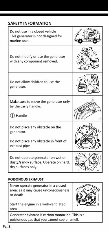
Do not use in a closed vehicleThis generator is not designed for marine-use.
Do not modify or use the generator with any component removed.
Do not allow children to use the generator.
Make sure to move the generator only by the carry handle.
① Handle
Do not place any obstacle on the generator.
Do not place any obstacle in front of exhaust pipe
Do not operate generator on wet or dusty/sandy surface. Operate on hard, dry surfaces only.
POISONOUS EXHAUST
Never operate generator in a closed area, as it may cause unconsciousness or death.
Start the engine in a well-ventilated area.Generator exhaust is carbon monoxide. This is a poisionous gas that you cannot see or smell.
Pg. 8
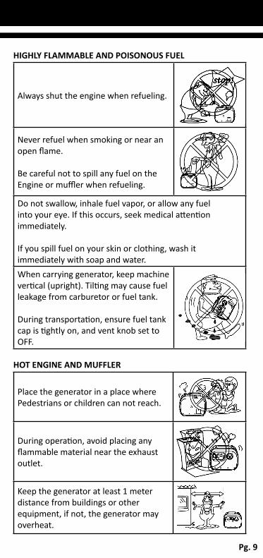
HIGHLY FLAMMABLE AND POISONOUS FUEL
Always shut the engine when refueling.
Never refuel when smoking or near an open flame.
Be careful not to spill any fuel on the Engine or muffler when refueling.
Do not swallow, inhale fuel vapor, or allow any fuel into your eye. If this occurs, seek medical attention immediately.
If you spill fuel on your skin or clothing, wash it immediately with soap and water.When carrying generator, keep machine vertical (upright). Tilting may cause fuel leakage from carburetor or fuel tank.
During transportation, ensure fuel tank cap is tightly on, and vent knob set to OFF.
HOT ENGINE AND MUFFLER
Place the generator in a place where Pedestrians or children can not reach.
During operation, avoid placing any flammable material near the exhaust outlet.
Keep the generator at least 1 meter distance from buildings or other equipment, if not, the generator may overheat.
Pg. 9

Do not operate the generator in a confined space or when covered with dust cover (or other materials).
Ensure the engine and muffler are completely cooled, before covering generator.
ELECTRIC SHOCK PREVENTION
Never operate generator in rain or snow to avoid electric shock.
Never touch the generator with wet hands, or electric shock may occur.
Connect the ground line of generator with ground (earth) terminal, and the other end to the ground electrode buried in the ground.
① Ground (earth) terminal
Pg. 10

CONNECTION NOTES
Avoid connecting the generator to commercial power socket. Avoid connecting the generator in parallel with any other generator.
① Correct ② Incorrect
! WARNING: Before connecting generator to a building’s electrical system, a licensed electrician must install an isolation (transfer) switch to main fuse box. The switch is the connection point for generator power and allows generator power or main line power to the building. This will prevent from charging the main power line (back feeding) when the main power supply has failed or has been turned off for a line repair. Back feeding can electrocute or injure line maintenance personnel. Also damage can occur when normal operation power returns if unit is used without an isolation switch.
Pg. 11

CTG2500i DIAGRAM① Vent knob② Fuel tank cap③ Fuel tank④ Handle⑤ Recoil starter handlebar⑥ Choke cable⑦ Control panel⑧ Muffler⑨ Main switch⑩ Engine oil cover (Plug)⑪ Drain screw, carburetor⑫ Air filter cover⑬ Spark plug cover
CONTROL PANEL① Smart-throttle switch (Eco-mode)② 12V DC charging socket③ DC protector④ AC socket⑤ AC socket⑥ Ground (earth) bolt/nut⑦ Low oil alarm⑧ Over load alarm⑨ Output indicator⑩ Reset button
ON/OFF SWITCH① OFF - Ignition circuit and fuel supply are off, and engine stops.
② ON - Ignition circuit and fuel supply are on, and engine can be started to work.
Pg. 12

SMART-THROTTLE SWITCH (ECO-MODE)① ON - When smart-throttle switch is in ON position, the economic control mode will automatically adjust the engine speed according to the connected load, so as to achieve low fuel consumption and low noise.
② OFF - When smart-throttle switch is in the OFF position, the engine will run at rated speed (5000rpm), regardless of load. ! NOTE: Smart-throttle switch must be in OFF position,
when applying to electric devices that require a large starting current, such as air conditioner, air compressor, submersible pump, or high-power DC equipment.
DC PROTECTORThe DC protector turns off automatically when DC load exceeds the rated output of generator or with a reverse connection on +/- .
! NOTE: If DC protector turns off, reduce the load to generator (to below the specified rated output). If it turns off again, consult your local dealer.
! NOTE: Press to reset DC protector.
① RESET ②
GROUND (EARTH) BOLT/NUT TERMINALMake sure ground (earth) terminal of generator is connected to avoid electric shock. When electric device is applied, generator should connect with earth ground.① Ground (earth) terminal
Pg. 13

LOW OIL ALARM (YELLOW)If engine oil level falls below the lower level, the low oil alarm will turn on, and the engine will stop automatically. Refill engine oil, otherwise engine will not start.
① Engine Oil Alarm
! NOTE: If engine won’t start, turn the main switch to ON position, then pull the recoil starter. If low oil alarm light flickers for a few seconds, it means engine oil is insufficient. Add engine oil and retry.
OVERLOAD ALARM (RED)Overload Alarm is Blinking - The overload alarm light (RED) ① will turn ON and blink when the total power of connected electrical devices is close to rated power.
Overload Alarm is ON - The overload alarm light will turn ON when it detects an overload of power to all connected devices. The electrical breaker will activate and stop the generator in order to protect it and connected devices. The AC output indicator (Green) will be off, and the overload alarm light (red) will stay on and the generator will not stop running.
When overload light is ON proceed as follows:
1. Disconnect all devices and press the reset button ①.
2. Reduce total wattage of electric devices below the output range
3. Check for blockages around cooling air inlet and control unit. If blocked, clear it.
Pg. 14

4. Restart the engine after checking.
! NOTE: The generator output automatically resets when engine is stopped and then restarted.
! NOTE: The overload indicator light may be ON for a few seconds at first when using electric devices that require a large starting current, such as air conditioner, air compressor, submersible pump, or high-power DC equipment. This is not a malfunction.
OUTPUT INDICATOR (GREEN)When the engine is started the output indicator turn ON (Green).
① Output indicator
FUEL TANK CAP VENT KNOBThe fuel tank cap has a vent to balance inner and outer pressure of fuel tank, and stop fuel flow. Turn vent knob clockwise from OFF to ON to allow fuel to flow into carburetor to allow the generator to start.
When generator is OFF or moved, ensure to turn vent knob counter clockwise from ON to OFF to avoid possible fuel overflow or vapor.
① Vent knob ② Fuel tank cap
RESET BUTTONIf the generator stops output due to an overload, disconnect all devices, reduce total wattage to within the application range, and press the reset button ①. The generator will recover to output.
Pg. 15
PRE-OPERATION CHECK! NOTE: Pre-operation checks should be made each
time before using generator.
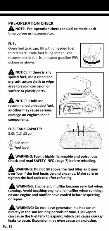
FUELOpen fuel tank cap, fill with unleaded fuel to red mark inside fuel filling screen. The recommended fuel is unleaded gasoline #93 octane or above.
! NOTICE: If there is any spilled fuel, use a clean and dry soft cotton cloth to wipe area to avoid corrosion on surface or plastic parts.
! NOTICE: Only use recommened unleaded fuel, as other may cause serious damage on engines inner components.
FUEL TANK CAPACITY5.0L (1.3 US gal)
① Red Mark② Fuel level
! WARNING: Fuel is highly flammable and poisonous. Check and read SAFETY INFO (page 7) before refueling.
! WARNING: Do not fill above the fuel filter as it may overflow if the fuel heats up and expands. Make sure to tighten the fuel tank cap after refueling.
! WARNING: Engine and muffler become very hot when running. Avoid touching engine and muffler when running, ensure engine and muffler have cooled before inspecting or repair.
! WARNING: Do not leave generator in a hot car or directly in the sun for long periods of time. Fuel vapors can cause the fuel tank to expand, which can cause cracks/leaks to occur. Expansion may even cause an explosion.
Pg. 16

ENGINE OILCheck the oil level by placing generator on a level surface and inspecting at the oil filter hole. The oil should be level with the Lower edge. Add oil if necessary.
① Lower edge, oil filter hole
! NOTICE: The generator leaves the factory without engine oil.
! NOTICE: Do not tilt the generator when filling engine oil. This may result in overfilling and potential damage to the generator.
RECOMMENDED ENGINE OILA: SAE15W-40 B: SAE10W-30 C: SAE5W-30
ENGINE OIL CAPACITY300 to 400ml (0.42US qt, 0.35Imp qt)
! NOTICE: Do not over fill, fill to oil indicator line only
GROUND (EARTH) BOLT/NUT TERMINALMake sure ground (earth) terminal of generator is connected to avoid electric shock. When electric device is applied, generator should connect with earth ground.① Ground (earth) terminal
Pg. 17

OPERATION INSTRUCTIONS! WARNING: Always operate generator in a well
ventilated area. Never operate generator in a closed in area as it may cause unconsciousness or even death within minutes.
! NOTE: Clean dust, dirt or water off the socket before use. Before starting the engine, do not connect any electrical devices.
! NOTICE: Read PRE-OPERATION CHECK (see page XX) carefully before operation of generator.
! NOTE: Generator can be used at rated output load in standard atmospheric conditions as follows:
• Ambient temperature - 25°C• Atmospheric pressure - 1000KPa• Relative humidity - 30%
The generator output may differ due to changes in temperature, altitude (the higher altitude, the lower air pressure) and humidity.
STARTING THE GENERATOR1. Hold the fuel tank cap to avoid it moving, and turn vent knob clockwise from OFF to ON, so as to open the vent hole. ① Vent knob
Pg. 18

2. Turn the main switch to ON position. This turns on the Ignition circuit and allows the fuel to flow.
3. Pull out choke cable button out completely. ① Choke cable button
! NOTE: Choke is not required when starting a warm engine. Set choke back to original position.
4. Pull slowly on the recoil starter handlebar until it is compressing, then pull hard.
! NOTE: Grasp generator by the carry handle firmly to prevent the generator from falling when pulling the recoil starter.
5. After the engine is started, allow engine to warm before pressing the choke button back to original position.
! NOTICE: Choke cable button should be moved back to original position when generator is warmed.
! NOTE: When starting generator, place smart-throttle switch in OFF position when there is no load on the generator.
• For ambient temperatures below 3°C (37°F), engine should run at rated speed for 5 minutes to warm up.
• For ambient temperatures above 3°C (37°F), engine should run at rated speed for 3 minutes to warm up.
• Once engine is warmed up, place smart-throttle switch to ON position (and run the generator in economy status).
Pg. 19

APPLICATION RANGEWhen using the generator, please make sure total load is under the range of generator rated output, or the generator may be damaged.
! NOTE: The overload alarm indi-cator ① is on (red) When total watts exceed the application range. (See page 17 for more details.)
CTG2500i
Power Factor Rated Output
AC 1.0 2100VA0.8 1680VA
DC -96W
12V/8A
! NOTICE: Do not overload. The total load of all electrical appliances must not exceed the supply range of the generator. Overloading will damage the generator.
When supplying precision equipment, PCs, electronic computers, mobile devices or battery chargers, keep the generator a sufficient distance away to prevent electrical interference.
This generator is not designed for medical applications.
Some electrical appliances or general-purpose electric motors have high starting currents, and may not run, even if they lie within the supply range given in the above table.
Pg. 20

AC CONNECTION (POWERING EQUIPMENT)! WARNING: Be sure all electric devices are turned off
before connection.
! NOTICE1. Be sure all electric devices including lines and plugs connections are in good condition before connecting to generator.2. Be sure the total load is within generator rated output.3. Be sure the socket load current is within socket rated current.
! NOTE: Make sure generator is connected to ground earth. When electric device is connected to ground earth, generator should connect ground earth.
STARTING THE ENGINE1. Start the generator.
2. Connect the plug with the AC socket.
3. Make sure the AC output indicator is ON (Green).
① AC output indicator
4. Turn the smart–throttle Switch to the ON position , and then turn on all electric devices.
! NOTICE: When using electric devices that require a large starting current, such as air-conditioner, compressor, submersible pump, or high-power DC equipment, the smart-throttle switch must be placed in OFF position.
Pg. 21

DC CONNECTION (BATTERY CHARGING)! WARNING: Never connect with VRLA (valve regulated
lead-acid) battery, which needs special (constant voltage) battery charging.
! NOTE: The generator rated DC voltage is 12V - 8 Amp.• Make connection to battery after starting engine• Clamp the red wire to the positive (+) terminal and
the black wire to the negative (-) terminal of the battery. ① Red cable ② Black cable
STARTING THE ENGINE 1. Start the generator.
2. Press the DC protector to reset and connect.
① RESET
②
3. Turn the smart-throttle switch to OFF position.
4. Connect charging line to battery terminal, and then plug to generator DC socket.
! NOTICE: Make sure the smart-throttle switch is in OFF position while charging battery and ensure battery lines are properly connected.
To avoid short circuit, connect charging line to battery terminal first, then to generator DC socket. After charging, disconnect the generator terminal first.
If DC protector turns OFF, reduce the load to the generators rated output. If it turns OFF again, consult your local dealer/service agent.
Pg. 22

! NOTE: At full charge, electrolyte specific gravity is between 1.26 and 1.28. Check specific gravity hourly to avoid over charging on battery.
! WARNING: During charging, do not smoke near or cut battery connection cable, as a spark may occur and cause a fire.
! WARNING: - Battery electrolyte is poisonous and dangerous, causing severe burns, etc. It contains sulfuric acid. Avoid contact with skin, eyes or clothing.
1. CONTACT WITH SPILL: Wash with water.2. CONTACT WITH EYES: Flush with water for 15
minutes and get prompt medical attention. 3. DO NOT CONSUME: If this occurs, contact medical
facility immediately. Drink large quantities of water or milk (milk with magnesia, beaten egg or vegetable oil) to dilute the sulfuric acid.
Batteries produce explosive gases. Keep sparks, flame, cigarettes, etc, away. Always ventilate when charging. Cover eyes when working near batteries. Keep battery out of reach of children.
STOPPING THE ENGINE! NOTE: Disconnect all electric devices.
Place smart-throttle switch in position of OFF.
1. Disconnect all electric devices.
2. Turn the main switch to OFF position.
3. Turn the vent knob to OFF position to close vent hole (when engine is completely cooled down).① Vent knob
Pg. 23

MAINTENANCEIt is an owners requirement to periodicly inspect, adjust, lubricate and maintain their generator to keep it in good working condition.
! NOTE: Use only genuine parts for replacement, contact Crommelins spare parts 1300 554 524.
! WARNING: Consult your local service agent for all major maintenance work.
! WARNING: Stop the engine before starting maintenance work.
Item DescriptionPre-
operationcheck
Every 6 months or 100 hour
Every 12 months
or 300 hour
Spark Plug Check condition, clean and replace if necessary ○
Fuel Check fuel level and leakage ○Fuel hose Check fuel hose for cracks or
damage. Replace if necessary. ○
Engine oilCheck oil level in engine ○Replace (1.) ○
Air filter element Check condition and clean ○ (2.)Flame retardant element
Check condition, clean and replace if necessary ○
Fuel screen Clean and replace if necessary ○Crankcase breather hose
Check breather hose for cracks or damage. Replace if necessary. ○
Cylinder head
Decarbonizes cylinder head more frequently if necessary ●
Valve clearance
Check and adjust when engine is cold. ●
Fittings/fasteners
Check all fittings and fasteners.Correct if necessary. ●
General inspection
Check machine over for any abnormality. ○
1. ENGINE OIL - Initial replacement of engine oil is after 1 month or 20 hours of operation.
2. AIR FILTER ELEMENT - When using in unusually wet or dusty areas, more frequent cleaning is required.
• 12 MONTH OR 300HR - Please contact local authorised service agent to conduct this service
Pg. 24

CARBURETOR ADJUSTMENTConsult your local service agent for any adjustments on the carburetor as special equipment is required for correct adjustment.
SPARK PLUG INSPECTION1. Remove spark plug cover and spark plug cap.
① Spark plug cover ② Spark plug cap
2. Locate spark plug socket on spark plug, turn it clockwise with wrench, and then disassemble spark plug.
③ Spark plug socket ④ Spark plug
3. Check for discoloration and remove the carbon (Standard electrode color: Medium-to-light tan color).
4. Check spark plug type and clearance. Spark plug: A5RTC (TORCH) Plug clearance: (a) 0.6mm
5. Install spark plug. Plug torque: 12~15N.m
6. Install spark plug cover.
! NOTE: When installing spark plug, twist it for 2-3 rounds by hand, and lock it up with specified torque value.
Pg. 25

ENGINE OIL REPLACEMENT ! WARNING: Never drain engine oil immediately after
turning off engine. Let the engine cool first to avoid scalding.
1. Place generator on a level surface, and start engine for few minutes to reduce the engine oil viscosity. Shut-off the engine, and turn the fuel tank cap vent knob to OFF.
2. Un-screw and remove oil filling cover. ① Screw ② Oil filling cover
3. Remove oil drain plug, place an oil pan under the engine, and tilt the generator to drain the oil completely. ③ Oil drain plug ! NOTE: It is your responsibility to dispose of waste
engine oil correctly.
4. Place generator on a level surface and add engine oil to lower level of filter port.
④ Lower level
! NOTICE: Do not tilt the generator when filling oil. This can result in overfilling and damage to the generator. Ensure no other material enters the engine crankcase.
RECOMMENDED ENGINE OIL: See page 15
5. Wipe any spilled oil around filter port, and tighten oil drain plug.
6. Re-install oil filling cover and screw tight.Pg. 26
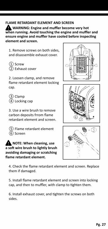
FLAME RETARDANT ELEMENT AND SCREEN! WARNING: Engine and muffler become very hot
when running. Avoid touching the engine and muffler and ensure engine and muffler have cooled before inspecting element and screen.
1. Remove screws on both sides, and disassemble exhaust cover.
① Screw② Exhaust cover 2. Loosen clamp, and remove flame retardant element locking cap.
③ Clamp④ Locking cap
3. Use a wire brush to remove carbon deposits frrom flame retardant element and screen. ⑤ Flame retardant element⑥ Screen
! NOTE: When cleaning, use a soft wire brush to lightly brush avoiding damaging or scratching flame retardant element.
4. Check the flame retardant element and screen. Replace them if damaged.
5. Install flame retardant element and screen into locking cap, and then to muffler, with clamp to tighten them.
6. Install exhaust cover, and tighten the screws on both sides.
Pg. 27

AIR FILTER REPLACEMENT1. Loosen screws and remove air intake cover.
① Screw② Air intake cover
2. Loosen screw, remove air filter cover, and take out filter element.
③ Screw④ Air filter cover⑤ Filter element
3. Wash the filter element in solvent and dry it.
4. Add a small ammount of engine oil to element and squeeze out any excess oil. The element should be wet, but not dripping.
Recommended filter oil:Foam-air-filter oil or SAE#20 lubricant oil.
! NOTICE: Do not 'wring out' the element sponge or may get damaged.
5. Insert the element into air filter.
! NOTE: Be sure the element sealing surface matches the air filter so as to not leak air.
! NOTICE: Never run the engine without element or it may cause excessive poisonous gas and cylinder wear.
6. Install air filter cover, and tighten it with screws.
! NOTE: When installing air filter cover, check and place the sealing strip on air filter correctly.
7. Assembly air intake cover, and tighten screws.
8. Install the mainenance door with the screwPg. 28

FUEL TANK FILTER1. Open fuel tank cap, and take out inlet filter screen. Remove fuel outlet line and take out fuel outlet filter screen.
① Fuel tank cap② Fuel filling filter screen ③ Fuel outlet pipe, fuel tank ④ Fuel outlet filter screen
2. Clean the fuel filling filter screen and fuel outlet screen with gasoline. Replace it if damaged.
3. Wipe fuel intake filter screen and outlet filter screen, and install them into fuel tank intake port and outlet port.
4. Install fuel tank cap and tighten it. Assemble fuel outlet pipe in correct position and tighten it with clamp.
! WARNING: Make sure to tighten fuel tank cap, and fuel pipe clamp.
TROUBLESHOOTING
ENGINE WILL NOT START1. No fuel supplied to combustion chamber.• There is no fuel in tank:
Add fuel• There is some fuel in tank:
Check vent knob on fuel tank cap, and turn it to position ON.
• Clogged fuel line: Clean fuel line.• Clogged carburetor: Clean carburetor.
Pg. 29

2. Low engine oil level: • Add engine oil to specified position.
3. Electrical system • Check main switch, and turn it to
position ON.
4. Poor spark• Spark plug
is dirty with carbon or wet: Remove carbon or wipe and dry spark plug.
• Check spark plug clearance is 0.5~0.7mm: Replace if it is over tolerance.
• Faulty ignition system: Consult dealer.
GENERATOR HAS NO OUTPUT1. For generator with reset function, disconnect all electric devices, reduce total wattage of connected electric devices within the application range, and press the reset button ①.
① Reset button
2. Press DC protector to position ON to reset the DC output.
Pg. 30

STORAGEFor long term storage of your machine, follow these preventive procedures to guard against deterioration.
DRAIN THE FUEL1. Remove fuel tank cap. Drain the fuel from fuel tank into an approved gasoline container by a commercially available hand siphon. Then install fuel tank cap.
2. Remove carburetor drain cover, loosen the drain screw on the carburetor float chamber, and drain the fuel from carburetor into an approved gasoline container.
① Drain screw ② Carburetor drain cover
3. Tighten carburetor drain screw, and install carburetor drain cover.
! WARNING: Fuel used in the machine is highly flammable and poisonous. Check SAFETY INFORMATION (page 9) carefully before adding the fuel. Make sure to wipe up any spilled fuel immediately to avoid damage on rubber or plastic parts.
4. Start the engine and let run until it automatically stops (As it has used all remaining fuel in carburetor).
PROTECT THE ENGINEIn order to protect engine, inside the cylinder, piston rings and other parts, please proceed as following steps:
1. Remove the spark plug, and pour about 5ml SAE10W\30 or 20W\40 engine oil into the spark plug hole and then re-install the spark plug. Pull the recoil starter several times to coat the cylinder wall, piston rings and other parts with engine oil.
2. Pull the recoil starter until you feel compression and then stop pulling (This prevents the cylinder and valves from rusting).
Pg. 31

CLEAN THE GENERATOR1. Clean the exterior part of the generator. Use only damp cloth with mild detergent. Avoid excess moisture.
2. Store the generator in a dry and well-ventilated place, with a clean cloth covered.
3. The generator must remain in a vertical position when stored, carried and operated.
TRANSPORTWhen transporting the generator;
1. Do not overfill the tank (there should be no fuel in the filler neck).
2. Do not operate generator while it is on a vehicle. The generator must be operated in a well ventilated area.
3. Avoid putting the generator on a vehicle exposed directly to sunlight. If the generator is left in an enclosed vehicle for many hours, the high temperatures inside the vehicle could cause fuel to vaporize resulting in possible explosion.
4. Do not drive on a rough road for an extended period with the generator on board. If you must transport the generator on a rough road, drain the fuel from the generator before hand.
5. Ensure Vent knob is turned to the OFF position.
IDENTIFICATIONThe machine identification series number is attached in the location as shown in drawing.
① Machine series number
SERIAL NUMBERS
___ ___ ___ ___ ___ ___(Write serial no.)
Pg. 32

WIRING DIAGRAM
Pg. 33

CTG2500i SPECIFICATIONS2.4kVA CROMTECH™ GENERATOR
Power Factor (kVA) 2.4kVA
Max. Wattage 2400watts
Cont. Wattage 2100watts
Type Single Phase
Voltage Regulation Inverter / Pure Sine Wave 2.5% THD
AC Output 240V - 50hz
Cromtech Engine LH148F(G)
Engine Type 4 stroke, air-cooled, single cylinder, OHV gasoline engine
Displacement 2.6kw, 79cc
Engine Oil 300-400ml
Fuel Tank 5.0L
Spark Plug A5RTC (TORCH)
Strarting System Recoil Start
Noise Level 52 - 59db at 7m*
Battery Charging 12V - 8Amp
USB (x2) 5V
Dimensions (LxWxH) 511x314x447mm
Weight 19.8kg
Package Dimensions 547x350x505mm
Run Time 5 to 20hours (depending on load)
*Noise level is measured when the smart-throttle switch is ON. LWA shows the sound power level under the ISO3744 standard test condition. The decibel rating is measured at 7m from the machine (Noise level may vary in different environments).
NOISE LEVELThe figures quoted are emission levels and are not necessarily safe working levels. Whilst there is a correlation between the emission and exposure levels, this cannot be used reliably to determine whether or not further precautions are required. Factors that influence the actual level of exposure of work-force include the characteristics of the work room, the other sources of noise, etc. i.e. the number of machines and other adjacent processes, and the length of time for which an operator is exposed to the noise. Also the permissible exposure level can vary from country.
Pg. 34

STANDARD FEATURES• Outlets (single phase - 15 Amp) x2• USB Charging (5V-2 Amp) x2• Battery charging (12V-8Amp)• Pure Sine Wave <2.5% THD suits precise instruments• Super quiet running at 52-59dbs• Low oil alarm, overload alarm, output indicator• Eco-mode adjusts output as load requires and lowers
noise• 5 to 20hrs continuous running (depending on load• Bonus protective yellow cover• 4-Stroke, forced air coole, OHV engine• 5.0L fuel tank• Lightweight & compact design• Recoil start with direct gravity fuel supply• Easy maintenance with quick convenient access ports• Durable, cast iron cylinder liner• 1 Year Cromtech warranty
APPLICATIONS• Camping• Caravanning & RVs• Home/small office backup power• Shop and production use• Precision Instruments• Small power tools• Fetes & Markets
Pg. 35
INDUSTRY• Recreation• Light industrial• Light commercial

www.crommelins.com.au
CROMTECH OUTBACK™ is a registered trademark ofCrommelins Operations Pty Ltd, ABN 11 008 889 656