2465a 2455a 2445a operators manual
TRANSCRIPT
8/2/2019 2465A 2455A 2445A Operators Manual
http://slidepdf.com/reader/full/2465a-2455a-2445a-operators-manual 1/182
T EKOPERATORS
MANUAL
070-6014-00
Product Group 38
2465A/2455A/2445AOSCILLOSCOPES
and OPTIONS

8/2/2019 2465A 2455A 2445A Operators Manual
http://slidepdf.com/reader/full/2465a-2455a-2445a-operators-manual 2/182
Copyright' 1986 Tektronix, Inc. All rights reserved.
Contents of this publication may not be reproduced in any
form without the written permission of Tektronix, Inc.
Products of Tektronix, Inc. and its subsidiaries are covered
by U.S. and foreign patents and/or pending patents.
TEKTRONIX, TEK, SCOPE-MOBILE, and Ill!!i are
registered trademarks of Tektronix, Inc. TELEQUIPMENT
is a registered trademark of Tektronix U.K. Limited.
Printed in U.S.A. Specification and price change privileges
are reserved.

8/2/2019 2465A 2455A 2445A Operators Manual
http://slidepdf.com/reader/full/2465a-2455a-2445a-operators-manual 3/182
NOTICE to the user/operator:
The German Postal Service requires that Systems assembled by theoperator/user 01 this instrument must also comply with Postal
Regulation, Vig. 1046/1984, Par. 2, Sect. 1.
HINWEIS Ilir den Benutzer/Betreiber:
Die vom Betreiber zusammengestellte Anlage, innerhalb derer dies
Geriit eingesetzt wird, muB ebenlalls den Voraussetzungen nach Par. 2,
Zift. 1 der Vig. 1046/1984 genugen.

8/2/2019 2465A 2455A 2445A Operators Manual
http://slidepdf.com/reader/full/2465a-2455a-2445a-operators-manual 4/182

8/2/2019 2465A 2455A 2445A Operators Manual
http://slidepdf.com/reader/full/2465a-2455a-2445a-operators-manual 5/182
Certificate of the Manufacturer/Importer
We hereby certify that the _ _ _4_6_5A--",--2_4_55_A--,,_2_4_45_A_0-,-S-,-C_IL __-,-0-,-SC-,-0__P,--E=-S,,-_
AND ALL INSTALLED OPTIONS
complies with the RF Interference Suppression requirements of
Amtsbl.-Vfg 1046/1984.
The German Postal Service was notified that the equipment is beingmarketed.
The German Postal Service has the right to re-test the series and toverify that it complies.
TEKTRONIX

8/2/2019 2465A 2455A 2445A Operators Manual
http://slidepdf.com/reader/full/2465a-2455a-2445a-operators-manual 6/182

8/2/2019 2465A 2455A 2445A Operators Manual
http://slidepdf.com/reader/full/2465a-2455a-2445a-operators-manual 7/182
Contents
Page
Illustrations. ............................. . .................. . ........................ iv
Tables ... . ............................................ . ...................... v
Operators Safety Summary" ................. .. ..... vi
The 2465A, 2455A, 2445A ....... .................. .. ........................................ ix
1 General Information
Preparation for Use...... . ...................................................... 1-1
Safety...... ................ ........................... .. ................. 1-1
Line Voltage Selection ......................................................................... 1-1
Line Fuse............................................... . . .................................... 1-1
Power Cord.. . .......... ... . ......................................... 1-3
Instrument Cooling ........ . . .................................... 14Start-up .......................... . ...............................................................14
Repackaging For Shipment. ..................................... . ................
2 OperationFundamentals..... ..................... ............... ......................... . ............... 2-1
Getting a Display ............... .. ...................... 2-1
Vertical .......................... . ............ 2-2

8/2/2019 2465A 2455A 2445A Operators Manual
http://slidepdf.com/reader/full/2465a-2455a-2445a-operators-manual 8/182
Contents
Page
3 Applications
Peak-to-Peak Voltage ....................... . ... 3-1
Absolute Voltages .............. ................. .. ..... 3-1
Noise Immunity....... ......................... ...... .......................... .. 3-2
"Quick and Dirty" DC Voltage Measurement........ .. .. 3-2
Amplitude Modulation ..... ............... ....................... . ... 3-2Frequency Modulation ............ ................. ............... ... 3-3
Measuring Video Signals in IRE Units ....... 3-4
Avoiding False Displays with Multi-Mode Signals.. 3-4
Algebraic Addition to Detect Coincidence or Cancel Interference.. 3-4
Observing Coincidence 01 Digital Signals ... .................................. 3-5
Measuring Off-Ground Signals And Cancelling Interference ............ 3-5
Period and Frequency .............. ................ ................ ................ ........... 3-6Rise Time and Fall Time ....... ............... .. ............. 3-7
Propagation Delay.. ............... ................. .. ............ 3-8
Setup and Hold Times ................................ 3-8
Slew Rate ......................... . ........................... 3-9
Time Ratio .......................... ........................... . ..... ..... ..... ..... ... 3-10
Phase Difference Between Two Signals .................................... . ..... 3-11
4 Checks and Adjustments
Introduction .... .......................... .. .................... 4-1

8/2/2019 2465A 2455A 2445A Operators Manual
http://slidepdf.com/reader/full/2465a-2455a-2445a-operators-manual 9/182
6 Performance Characteristics
Performance Conditions
7 Options and Accessories
Introduction ...
Contents
Page
.................. 6-1
.................. 7-1
Option 11.................. . ............................ 7-1
Option 1R ................ . ............................. 7-1
Power Cord Options ............................................................................. 7-2
Standard Accessories. 7-3
Optional Accessories ........................................................................... 7-4
A AppendixA
Extended Functions with Diagnostic Exercisers ....................................... A-1
B AppendixB
Sequence Programming and Operation...... .......... ...... .......................... B-1
Executing Sequences ............................................................................ B-3
C AppendixC

8/2/2019 2465A 2455A 2445A Operators Manual
http://slidepdf.com/reader/full/2465a-2455a-2445a-operators-manual 10/182
Contents
Illustrations
Figure Page
1·1 Line selector switch, line fuse, and detachable power cord ...... ........... 1-3
2-1 Readout display locations ..... 2-9
3·1 Instantaneous voltages ............................... .. 3-1
3·2 Eliminating common.mode signals ............... . .. ............ 3-6
3-3 Measuring rise times .. .. ................... 3-7
3-4 Time between two pulses (cursor method) . .. .................. 3-9
3·5 Time ratio (duty factor) .... .......................... ......... . ...... .. .... 3-10
3·6 Phase difference between two signals ....... .................. .. .......... 3-11
3·7 Small.angle phase difference ....... ...... " ... . .. ......................... 3-11
4-1 Probe low.frequency compensation ..... .. .... 4-3
Power and display controls .. .. ............................. 5·3
SETUP and MODE buttons, and CH 1 and CH 2 POSITION controls. 5-5
Channell and Channel 2 controls and connectors ...
5-1
5-2
5-3
5-4
5-5
5-6
5-7
CH 3 and CH 4 controls and connectors and CALIBRATOR output.. ...... ..5-75-9
Horizontal and delta measurement controls .... ................. .
Trigger controls and indicators .....................................
Rear panel controls and connectors .. ..
5-11
.. ............ 5-18
.......... 5-26

8/2/2019 2465A 2455A 2445A Operators Manual
http://slidepdf.com/reader/full/2465a-2455a-2445a-operators-manual 11/182
Contents
Tables
Table Page
1-1 Power Cord and Voltage Data .................. . .................................... 1-2
2-1 Resolution Selections................. ................ .. .................................... 2-21
2-2 Auto Resolution ............................................................................................ 2-21
2-3 Delay-by-Events Combinations................................ . ............................. 2-24
2-4 Sweep Triggering ........................................................................................... 2-29
6-1 2465A/2455A/2445A Electrical Characteristics ..... ...... ...... ...... ...... ....... ... .... 6-6
6-2 Option 01 (DMM) Electrical Characteristics .................................................. 6-156-3 Option 05 (TV) Electrical Characteristics ...................................................... 6-22
6-4 Option 06 (C/TIT) Electrical Characteristics .................................................. 6-24
6-5 Option 09 (WR) Electrical Characteristics ..................................................... 6-31
6-6 Option 10 (GPIB) Electrical Characteristics ................................................... 6-336-7 Mechanical Characteristics ............................................................................ 6-34
6-8 Environmental Requirements ................................... ................. . ........... 6-36
C-1Confidence Test
Numbers and Affected Functions................. .
............. C-2

8/2/2019 2465A 2455A 2445A Operators Manual
http://slidepdf.com/reader/full/2465a-2455a-2445a-operators-manual 12/182
Operators Safety Summary
The general safety information in this part of the summary is for both operating
and servicing personnel. Specific warnings and cautions will be found
throughout the manual where they apply and do not appear in this summary.
Terms
In This Manual
CAUTION statements identify conditions or practices that could result in
damage to the equipment or other property.
WARNINGstatements identify conditions or practices that could result
in
personal injury or loss of life.
As Marked on Equipment
CAUTION indicates a personal injury hazard not immediately accessible as one
reads the markings, or a hazard to property. including the equipment itself.
DANGER indicates a personal injury hazard immediately accessible as one
reads the marking.
Symbols

8/2/2019 2465A 2455A 2445A Operators Manual
http://slidepdf.com/reader/full/2465a-2455a-2445a-operators-manual 13/182
Operators Safety Summary
Power Source
This product is intended to operate from a power source that does not apply more
than 250 volts rms between the supply conductors or between either supply
conductor and ground. A protective ground connection by way of the grounding
conductor in the power cord is essential for safe operation.
Grounding the Product
This product is grounded through the grounding conductor of the power cord. To
avoid electrical shock, plug the power cord into a properly wired receptacle before
connecting to the product input or output terminals. A protective ground
connection by way of the grounding conductor in the power cord is essential for
safe operation.
Danger Arising From Loss of Ground
Upon loss of the protective-ground connection, all accessible conductive parts
(including knobs and controls that may appear to be insulating) can render an
electric shock.
Use the Proper Power CordUse only the power cord and connector specified for your product.
Use only a power cord that is in good condition.

8/2/2019 2465A 2455A 2445A Operators Manual
http://slidepdf.com/reader/full/2465a-2455a-2445a-operators-manual 14/182

8/2/2019 2465A 2455A 2445A Operators Manual
http://slidepdf.com/reader/full/2465a-2455a-2445a-operators-manual 15/182
The 2465A, 2455A, and 2445A
The TEKTRONIX 2465A, 2455A, ano 2445A portable oscilloscopes have four
vertical channels with DC to 350 MHz, 250 MHz, and 150 MHz bandwidths.
Deflection factors run from 2 mV to 5 V per division, in a 1-2-5 sequence, with either1 Mn or 50 n input resistance, in channels 1 and 2. Either AC or DC input coupling is
available at 1 Ma. Channels 3 and 4 give 0.1 V or 0.5 V per division, with 1 Mf! input
resistance, and DC coupling. With the standard 10X probes, channels 1 and 2 display
20 mV to 50 V/division and channels 3 and 4 display 1 V or 5 V/division.
The trigger systems work automatically for most signals. They operate in various
modes, from any channel, with couplings for a wide range of signals. The 2445A
triggers from DC to 250 MHz. The 2455A and 2465A trigger from DC to 500 MHz.
Sweep speeds range from 1.5 s to 1 ns per division on the 2445A and 2455A and
to 500 ps per division on the 2465A, including the effects of the X10 magnifier and the
calibrated variable between 1-2-5 steps. Horizontal displays include A·Sweep, B
Sweep (delayed), A alternated with 8, and CH 1 (for XIV displays).
The SETUP features, AUTO, SAVE, and RECALL, save time and prevent errors,
whether you are a novice operator or a master. AUTO Setup works with almost any
signal. For repeating measurements, the Save and Recall functions record and restore
as many as 30 instrument setups, including the extended-function options. Setups can
be recalled either immediately or sequentially.
Digital readouts of time, voltage, scale factors, trigger levels, and auxiliary
information also save time and reduce errors.
With the available Counter/Timer/Trigger (CIT), Option 06 or Option 09,

8/2/2019 2465A 2455A 2445A Operators Manual
http://slidepdf.com/reader/full/2465a-2455a-2445a-operators-manual 16/182

8/2/2019 2465A 2455A 2445A Operators Manual
http://slidepdf.com/reader/full/2465a-2455a-2445a-operators-manual 17/182
SECTION
1General Information
.
00
f( ' \

8/2/2019 2465A 2455A 2445A Operators Manual
http://slidepdf.com/reader/full/2465a-2455a-2445a-operators-manual 18/182

8/2/2019 2465A 2455A 2445A Operators Manual
http://slidepdf.com/reader/full/2465a-2455a-2445a-operators-manual 19/182
Genera/Information
Preparation for Use
Safety
Before connecting the oscilloscope to a power source, read entirely both thissection and the Safety Summary at the front of this manual. Be sure you have the
training required to safely connect the instrument inputs to the signals you will be
measuring. Refer to the Safety Summary for power source, grounding, and other
safety considerations pertaining to the use of the instrument.
This instrument may be damaged if operated with the LINE VOLTAGE
SELECTOR switch set for the wrong applied ac input-source voltage or if
thewrong
line fuseis installed.
Line Voltage Selection

8/2/2019 2465A 2455A 2445A Operators Manual
http://slidepdf.com/reader/full/2465a-2455a-2445a-operators-manual 20/182
General Information
Table 1-1
Power Cord and Voltage Data
Plug Power Cordi Line Voltage Reference
Configuration Option Plug Type Selector Standardsb
,/'"ANSI G73,11
- - r ; ~ ~ } ' ~ U,S, U,S, NEMA 5-15-P
Std, 120V 115V lEG 83
UL 198,6
~ - ' / ? " F ' < ; ' - " EURO GEE(7), II, IV, VII
~ ~ > , ~ ( ) : : : Al 220V 230V lEG 83
lEG 127
i=;:f UK' BS 1363
'fI-' ,A2 240V 230V lEG 83~ 1 [ " : ' lEG 127
' ~ ~ Australian
A3 240V 230V AS Gl12' ,_:1 ,
lEG 127

8/2/2019 2465A 2455A 2445A Operators Manual
http://slidepdf.com/reader/full/2465a-2455a-2445a-operators-manual 21/182
General Information
LINE FUSE
CAunON
"roc".,'""",,, "",.' ,.>";,,,",,"",,,,,,,.,, ...,'"""Of.' "", '",,« ,',"'" '>"." '", .K '"

8/2/2019 2465A 2455A 2445A Operators Manual
http://slidepdf.com/reader/full/2465a-2455a-2445a-operators-manual 22/182
General Information
Instrument Cooling
To prevent instrument damage from internally generated heat, adequate air flow
must be maintained. Before turning on the power, verify that the spaces around the
air-intake holes on the bottom of the cabinet and the fan-exhaust holes in the rear
panel are free of any obstruction to airflow.
Start-up
The oscilloscope automatically performs a set of diagnostic tests each time the
instrument is turned on. These tests warn the user of any available indication that
the instrument may not be fully functional. The tests run for several seconds afterpower is applied. If no faults are encountered, the instrument operates normally. A
failure of any of the power-up tests will be indicated by either a flashing TRIG'O
indicator on the instrument front panel or a bottom-line readout on the CRT in the
form: TEST XX FAIL VV (where XX is the test number and YY is the failure code
of the failed test).
If a failure of any power-up test occurs, the instrument may still be usable for
some applications. To operate the instrument after a power-up test failure, press
the AlB TRIG button. Even if the instrument then functions for your particular

8/2/2019 2465A 2455A 2445A Operators Manual
http://slidepdf.com/reader/full/2465a-2455a-2445a-operators-manual 23/182
General Information
Repackaging For Shipment
If this instrument is to be shipped by commercial transportation, it should be
packaged in the original manner. The carton and packaging material in which your
instrument was shipped to you should be retained for this purpose.
If the original packaging is unfit for use or is not available, repackage the
instrument as follows:
1. Obtain a corrugated cardboard shipping carton having inside dimensions at
least six inches greater than the instrument dimensions and having a carton
test strength of at least 275 pounds.
2. If the instrument is to be shipped to a Tektronix Service Center for service or
repair, attach a tag to the instrument showing the following: owner of the
instrument (with address), the name of a person at your firm who can be
contacted, complete instrument type and serial number, and a description of
the service required.
3. Wrap the instrument with polyethylene sheeting or equivalent to protect the
outside finish and prevent entry of packing materials into the instrument.
4. Cushion the instrument on all sides by tightly packing dunnage or urethane
foam between the carton and the instrument, allowing three inches on each

8/2/2019 2465A 2455A 2445A Operators Manual
http://slidepdf.com/reader/full/2465a-2455a-2445a-operators-manual 24/182

8/2/2019 2465A 2455A 2445A Operators Manual
http://slidepdf.com/reader/full/2465a-2455a-2445a-operators-manual 25/182

8/2/2019 2465A 2455A 2445A Operators Manual
http://slidepdf.com/reader/full/2465a-2455a-2445a-operators-manual 26/182

8/2/2019 2465A 2455A 2445A Operators Manual
http://slidepdf.com/reader/full/2465a-2455a-2445a-operators-manual 27/182
Operation
Fundamentals
Like any oscilloscope, this instrument draws a graph of voltage as a function of
time. The VERTICAL controls, marked off by a heavy gray line, define the voltage axis
of the display. SEC/DIV, X10 MAG, and horizontal POSITION control the time axis of
the display. The TRIGGER controls, marked off by a green box, define the signals
required to initiate sweeps across the time axis. The controls under the CRT affect the
display but not the waveform.
Getting a Display
1. Connect a probe from the input of a Vertical channel to a signal.
2. Select the channel using the Vertical MODE buttons. You may select any
combination of vertical channels (if you are using the standard accessory
probes, make sure the CH 1 and CH 2 input are not set at 50 Q).
3. Press AUTO Setup to initialize vertical, horizontal, trigger, and display intensity
for a usable display. (If STEP is illuminated, first push RECALL to extinguish
it.)
4. If the resulting display isn't exactly what you want, adjust the appropriate
VOLTS/DIV, SEC/DIV, POSITION, or Trigger controls.

8/2/2019 2465A 2455A 2445A Operators Manual
http://slidepdf.com/reader/full/2465a-2455a-2445a-operators-manual 28/182
Operation
Vertical
For voltage measurements, set VOL TS/DIV VAR fully clockwise. For best
accuracy. set VOLTSIDIV for the largest display possible.
Input Coupling
Use 1 MIl DC input mode for most applications. This mode is compatible
with the standard accessory, high-impedance probes and it displays logic levels
and dc levels of static signals. Use the pair of buttons near the CH 1 and CH 2
inputs to select input coupling. CH 3 and CH 4 inputs are fixed at 1 MQ DC.
GND input mode shows where the O-volt level will be displayed with DC
coupling.
Use AC coupling for the special cases where you need to see small
signals on large dc voltages.
Use the 50 Il DC input mode for the best possible vertical performance
with active probes, 50-12 signal sources, and low-impedance passive
probes. A low-impedance probe can present less than 2 pF load to the
signal-source, in parallel with 500 Q or 5000 n with 10X or 100X
attenuation.

8/2/2019 2465A 2455A 2445A Operators Manual
http://slidepdf.com/reader/full/2465a-2455a-2445a-operators-manual 29/182
Operation
Channel Selection
Using the Vertical MODE buttons, you can display any combination of the
four vertical channels. To manually switch between CH 1 and another channel,
with minimum button pushing, deselect CH 1 and press the button for the other
channel to turn it on and off; CH 1 is displayed when all other verticals are off.
ADD and INVERT
Press ADD to display the algebraic sum of CH 1 and CH 2. Select INVERT
to change the sense of the CH 2 waveform or to see the difference between
CH 1 and CH 2 on the ADD trace. If you use ADD, the CH 1 and CH 2
VOL TS/DIV settings should be equal.
Choosing CHOP or AL T
With two or more channels, the display is time-shared. Chop mode displays
each channel for a short time and multiplexes during the sweep to give the
appearance of displaying all channels at once. Chop works better than Alt for
sweeps slower than 1 ms/division and for low repetition-rate signats that makethe display flicker, up to 2 ~ s / d i v i s i o n .

8/2/2019 2465A 2455A 2445A Operators Manual
http://slidepdf.com/reader/full/2465a-2455a-2445a-operators-manual 30/182
Operation
Horizontal
The A-Sweep is the only horizontal function you need for most applications. The A
SWP indicator is on when the A-Sweep is displayed. To make sure the A-Sweep is
displayed. press AUTO Setup and push SEC/DIV in. You can also restore the A
Sweep display by pushing the SEC/DIV knob in and turning it counterclockwise until
the A SWP indicator lights. If both A SWP and B SWP indicators are of(, pushSEC/DIV in and turn it clockwise to escape the X/V display mode.
The X10 MAGnifier expands the center of the unmagnified waveform.
For best measurement accuracy, set SECIDIV for the fastest sweep that willdisplay the interval of interest and set VAR fully clockwise.
See "Delayed Sweep Operation" for more information about B-Sweep, B-Trigger,
and trace separation.
Trigger Controls

8/2/2019 2465A 2455A 2445A Operators Manual
http://slidepdf.com/reader/full/2465a-2455a-2445a-operators-manual 31/182
Operation
Normal mode produces a sweep only when the trigger signal meets the Leveland Slope criteria.
Use Normal mode for infrequent events and erratic signals.
5g1 Seq mode accepts one trigger for each sweep in the display. Press thelower Mode button to arm the trigger and illuminate the READY indicator for
each sequence. With a multi-trace display, a sequence comprises up to sixteen
sweeps.
Use 5g1 Seq to detect a rare event or to eliminate all but the first one of a
chaotic burst of pulses. Set the trigger for the signal of interest in Normal mode.Then press the lower Mode button to select 5g1 Seq and illuminate the READY
indicator. To detect the occurrence of a rare event, display a single trace and
arm 5g1 Seq with the trigger set for the event. Periodically check to see if
READY is on. If a burst of trigger events occurs, the sweep runs once for each
trace displayed and READY extinguishes.
Trigger Source

8/2/2019 2465A 2455A 2445A Operators Manual
http://slidepdf.com/reader/full/2465a-2455a-2445a-operators-manual 32/182
Operation
Trigger Slope
Press SLOPE to select the rising (+) or falling ( - ) edge of the signal to
trigger the sweep.
Trigger Level
INIT@50% sets the trigger level near the midpoint between signal peaks, in
any mode. Some signals below 50 Hz may not produce the correct level setting.
LEVEL gives you complete freedom to choose the most appropriate
threshold voltage on a signal to initiate sweeps, in case neither the Auto Lvi
mode nor INIT@50% provides a suitable threshold.
Trigger Holda"
With irregular signals such as bursts, the Trigger HOLDOFF setting can
improve display stability. Also, if the signal has a fixed pattern of variation from
cycle to cycle, some modes of the signal may be omitted from the display.Changing the Holdoff setting can force the instrument to display all the modes
of the signal. Normally, HOLDOFF should be set at MIN.

8/2/2019 2465A 2455A 2445A Operators Manual
http://slidepdf.com/reader/full/2465a-2455a-2445a-operators-manual 33/182
Operation
To trigger at a specific video line:
1. Select a composite video signal as the trigger source.
2. Select FLD1, FLD2, or AL T coupling.
3. Set SLOPE to the polarity of the sync.
4. Turn FLO LINE # p.) to the desired line number.
When you increment or decrement the line number outside the range of the
selected field, the other field is automatically selected.
With AL T field coupling, the line number is referred to the beginning of both
fields.
To compare two video signals with the same format that are not periectly
synchronized. such as from a camera and a VCR or from the input and output of a
time base corrector:
1. Display the signals on CH 1 and CH 2, with Alt Vertical mode.

8/2/2019 2465A 2455A 2445A Operators Manual
http://slidepdf.com/reader/full/2465a-2455a-2445a-operators-manual 34/182
Operation
Readout
To aid waveform interpretation, the readout shows scale factors, delta
measurements, delay times, trigger settings, and other information. To display all
readout information, set the READOUT INTENSITY control clockwise from OFF
(SCALE FACTORS ON). See Figure 2-1.
Trigger Readout
The trigger readout shows wh'lch trigger (A or B) is affected by the controls
(Mode, Source, Coupling, Slope, Level, and INIT@50%), which channel (1-4) is
supplying the trigger signal, and the voltage at which triggering takes place,
with the following settings:
Trigger Coupling
Trigger Source
Vertical Input
VOLTS/DIV VAR
DC or Noise Reject
Any Single Channel
Dc or Gnd
Fully Clockwise.
If the trigger comes from the word recognizer, which is available with the
CTT, the readout shows the defined word.

8/2/2019 2465A 2455A 2445A Operators Manual
http://slidepdf.com/reader/full/2465a-2455a-2445a-operators-manual 35/182
Operation
TRIGGER TRIGGER SO fISOURCE LEVEL OVERLOAD
(1,2,3, OR 4) INDICATOR INDICATION
TRIGGER _ ~ l fl-, Et'-----' 'WEE 'URRENTLY ----...!" ro "" - - - I DELAY TIMEUNDER CONTROL I L- _I DELTA VOLTAGE
(AorB) --c.: _ _ DELTA TIME
~ i o o ~ t t 1 DELTA TIME
SErue N U M B E R ~ 1 j It I M-ND NAME __ _
I +-l +---:-f-----f---+- CHANNel 4CHANNEL 2 f-" + + -ttH ·..-+-+-t-r--+tj SCALE
, ~ ~ \ i R 1- .--:--r--± I
!i i h ::.:
IN::::::L,' f ..··[ •..• ;.tt l-. ri.""";::'-:::' >.' .. + , - i j i ~ ' : D ~ ~ ~ ~ : R , ~ " c ~ \ i R ----r-",- •:.:... •• Tf'l' ." ·.... l'L .' - , ~ " c ~ \ i R
INVERTINDICA TOR (_)
BANDWIDTH A SWEEPLIMIT SCALE
INDICATOR FACTOR(BWl)
CHANNEL 3SCALE
FACTOR
5854-03

8/2/2019 2465A 2455A 2445A Operators Manual
http://slidepdf.com/reader/full/2465a-2455a-2445a-operators-manual 36/182
Operation
Measurements with Cursors
The controls in the gray box (J.V, J.t, TRACK/INDEP, J. REF OR DLY POS, and J.)
operate cursors and sweep delays. With the cursors, you can measure voltage, time,
frequency, ratios, and phase. We often refer to the ..l REF OR DL Y POS control as "..l
REF" for convenience.
Cursors are more accurate and easier to use than the graticule. They eliminate the
inconvenience and errors of counting and interpolating graticule markings and they
avoid CRT linearity errors.
For best..lV accuracy, display the signal on either CH 1 or CH 2 with VOLTS/DIVset for three to eight divisions of waveform amplitude. For best..lt and l/. .lt accuracy.
use the fastest sweep that will include the interval of interest.
Measure Voltage
1. Turn on the..lV cursors and readout with the..lV button.
2. Align the cursors with points of interest, such as waveform peaks. using
the..l REF and ..l knobs.
Operation

8/2/2019 2465A 2455A 2445A Operators Manual
http://slidepdf.com/reader/full/2465a-2455a-2445a-operators-manual 37/182
Measure Frequency with Cursors
1. Turn on the 1/.lt cursors and readout by pressing the.lV and.lt
buttons together.
2. Align the cursors with identical points, such as zero crossings, on
adjacent cycles of the waveform, using the j , REF and.l knobs.
3. The readout shows the frequency of the signal.
4. Press.lV and .lt together or press either .l button twice to turn off the
1/.l t cursors and readout.
Measure Voltage Ratio, Time Ratio (such as Duty Factor), or
Phase
1. Set VOL TS/DIV or SEC/DIV so a feature of the waveform which you
consider the 100% reference covers more than five divisions of the
graticule.
2. Turn the VOLTS/DIV VAR or SEC/DiV VAR counterclockwise from the
detent until the 100% reference feature covers exactly five divisions.
You can use one signal as a refereilce and compare others to it. Forphase, set one cycle, which is the 360 degree reference, to five
divisions.
Operation

8/2/2019 2465A 2455A 2445A Operators Manual
http://slidepdf.com/reader/full/2465a-2455a-2445a-operators-manual 38/182
Display Operation
Set both INTENSITY and READOUT INTENSITY controls for comfortable viewing,
but no brighter than you need. Use high intensity settings to observe low repetition
rate signals, narrow pulses in long time intervals, or occasional variations in fast
signals.
Signal Connections
A probe is usually the most convenient way to connect an input signal to the
instrument. Shielded to prevent pickup of electromagnetic interference, the standard
10X probes supplied with the instrument present a high impedance to a circuit under
test. While the 10 Mn and 11 pF of the probe are a negligible load on most circuits,very fast circuits or very high impedance circuits may be seriously affected.
Waveform Fidelity and Probe Grounds
A probe ground mustbe
used for accurate measurementsand
observations.Use the shortest ground connection possible if you want good waveform
fidelity.
Operation

8/2/2019 2465A 2455A 2445A Operators Manual
http://slidepdf.com/reader/full/2465a-2455a-2445a-operators-manual 39/182
Probe Handling
Both the probe and the probe accessories should be handled carefully to
prevent damage. Striking a hard surface can damage both the probe body and
the probe tip. Exercise care to prevent the cable from being crushed, kinked, or
excessively strained.
Coaxial Cables
To maintain good waveform fidelity and accuracy, only high-quality, low-loss
coaxial cables should be used. The instrument is optimized for 50 Q sources,
driving the 50 n dc input through 50 n cable. If you use another signal source
impedance, such as 75 n, use the appropriate coaxial cable and an external
terminator to match, with the input set at 1 MO. Some high frequency response
will be lost with external termination.
Magnify Waveform Details with Delayed-Sweep
1. Display a waveform with the A-Sweep, then pull SEC/DIV out to activate B
Sweep and light both the A SWP and B SWP indicators (INTEN mode).
2. If a B-Trigger Mode indicator is on, select RUN AFT DLY. (If an A-Trigger

8/2/2019 2465A 2455A 2445A Operators Manual
http://slidepdf.com/reader/full/2465a-2455a-2445a-operators-manual 40/182
Operation

8/2/2019 2465A 2455A 2445A Operators Manual
http://slidepdf.com/reader/full/2465a-2455a-2445a-operators-manual 41/182
De/ta-De/ay-Time
Use the delayed (B) sweep to magnify both ends of a time interval for the best
measurement accuracy available. Appendix D gives relative accuracies of the various
time-measurement techniques.
Measure Time or Frequency with Delta-Delay-Time
1. Display the time interval or signal period with the A Sweep running as
fast as possible, unmag nified, up to one speed slower than the fastest
SEC/DIV setting. If the interval is a propagation delay or other two
signal measurement, display the signals on CH 1 and CH 2 and trigger
A Sweep on the earlier of the two.
2. Pull SEC/DIV out to activate B Sweep and light the A SWP and B SWP
indicators (lNTEN mode). (If you inadvertently chose the fastest A
Sweep speed, the CH2 Delay Match function will be active. See the
"Operator Checks and Adjustments" section.)
3. If a B-Trigger Mode indicator is on, select RUN AFT DLY. (If an A
Trigger Mode indicator is on, the B-Trigger has been set previously toRUN AFT DLY.)
4. Select t>t or 1/t>t while the SEC/DIV knob is out.
Operation

8/2/2019 2465A 2455A 2445A Operators Manual
http://slidepdf.com/reader/full/2465a-2455a-2445a-operators-manual 42/182
De/ta-De/ay-Time Measurement Characteristics
A delta-delay-time measurement is valid between a pair of pointssuperimposed on the pair of B Sweeps, regardless of display positions, Trace
Sep setting, and CRT-distortion errors. In other words, the only points that can
be superimposed are those points that are separated by the delta-time value.
(Good accuracy for short intervals does depend on correct CH 2 DL Y
adjustment. See "Operator Checks and Adjustments" section.)
The main sweep trigger event begins the interval of interest for manymeasurements. The delta-delay-time measurement can include the A-Sweep
trigger event with A SEC/DIV set faster than 50 p.S. If an interval begins less
than 0.05 division from the beginning of A Sweep, the readout shows a
question mark. Move.). RE F clockwise and change the A-Trigger controls as
required to eliminate the question mark and still see a suitable waveform feature
for the beginning of the interval.
Sing/e-De/ay-Time Measurements
For intervals longer than 10 P.s or for low repetition rate signals that make the
display flicker, you may prefer to use the B Sweep without.1t. Without ~ t , the display
repetition rate is higher and the Diy readout shows the time from the start of A Sweepto the start of B Sweep. Compared to delta-delay-time measurements, some accuracy
will be lost, unless you can take the difference between one delay time and another.
Operation

8/2/2019 2465A 2455A 2445A Operators Manual
http://slidepdf.com/reader/full/2465a-2455a-2445a-operators-manual 43/182
Precision Timing
The available Counter/Timer/Trigger (CIT) directly and precisely measures any
interval defined by the delayed (8) Sweep and the 8 Trigger. The CIT also reduces
the effort required for repetitive measurements or measurements on changing signals.
Direct and Indirect Measurements
AS the counter completes each direct measurement, the last character of the
units symbol blinks. If the readout includes the word "SET: it indicates an
indirect measurement of delay-time, including delta-delay-time or 1Jdelta-delay
time. Indirect measurements are inferred from the A Sweep and control
settings.
Indirect delay-time measurements are displayed when any Count, Delay-by
Events, or Logic-Trigger function of the CIT s active, except 8 Sweep
triggered by the Word Recognizer. Indirect measurements are also displayed for
a few seconds when 6. REF or 6. are adjusted. Moving any control that affects
direct measurements produces an indirect reading until a new, direct
measurement is complete.
Direct, counted measurements may be different from indirect ("SET")
measurements for any of the following reasons:
Operation

8/2/2019 2465A 2455A 2445A Operators Manual
http://slidepdf.com/reader/full/2465a-2455a-2445a-operators-manual 44/182
Triggered Delta-Delay-Time Measurements
The available Counter-Timer-Trigger (Crr) directly measures intervals defined by
the B-Sweep delays and B Trigger. B Trigger with and 1/dt can have different
sources, levels, and slopes for the pair of B-sweeps. Repeatedly pressing the lower
Mode button selects the following sequence of B-Trigger modes with the noted
characteristics;
With or without LIt or tlLlt:
RUN AFT DLY
B Sweepruns
immediately after the set delay.
Without LIt or tlLlt:
TRIG AFT DLY
B Sweep runs at the first trigger after the set delay.
With LIt or 1/Llt:
Operation

8/2/2019 2465A 2455A 2445A Operators Manual
http://slidepdf.com/reader/full/2465a-2455a-2445a-operators-manual 45/182
Measure a Time Interval Defined by the 8 Trigger
1. Follow the first five steps of the procedure in • Measure Time or
Frequency with Delta-Delay-Time," earlier in this section.
2. If the interval is a propagation delay or other two-signal measurement,
select AlT Vertical Mode and be sure A-Trigger Source is a single
channel. Note that .:l REF controls the intensified zone on the CH 1
trace.
3. Select TRIG , l DlY B-Trigger Mode. For the special case of a
measurement on one signal where the beginning and end of the interval
have the same slope and threshold, select TRIG AFT DlY and TRIG
Ll DLY (both indicators on).
4. Set B-Trigger Source to VERT. If the measurement is limited to one
signal and more than one signal is displayed, either deselect the othersignals or set Source to the appropriate channel.
5. Set B-Trigger Coupling to DC. For unusual applications, other couplings
may be preferred.
6. Press INIT@50%. If necessary, adjust LEVEL for the desired trigger
threshold.
7. Select TRIG AFT DlY Mode and repeat step 6. (For the special case
noted in step 3, skip this step.)
8. If required, readjust REF and to intensify the transitions that mark

8/2/2019 2465A 2455A 2445A Operators Manual
http://slidepdf.com/reader/full/2465a-2455a-2445a-operators-manual 46/182
Operation

8/2/2019 2465A 2455A 2445A Operators Manual
http://slidepdf.com/reader/full/2465a-2455a-2445a-operators-manual 47/182
A SEC/DIY
10 ns to 500 ms
1 0 n s t 0 5 ~ s
10"5
to50"5
100"5 to 500"5
1 ms to 5 ms
10 ms to 50 ms
100 ms to 500 ms
Table 2-1
Resolution Selections
Selection Least Digit
AUTO See Table 2-2
10 ps 10 ps
tOO ps 100 ps
1 ns 1 ns
10 ps or 100 ps100 ps
1 ns 1 ns
10pstolns 1 ns
Any 10 ns
Any 100 ns
Any 1 "5
N for Average
See Table 2-2
> 106
> to '
> 100
>10'
> 100
> 100
> 1
> 1
> 1
Operation

8/2/2019 2465A 2455A 2445A Operators Manual
http://slidepdf.com/reader/full/2465a-2455a-2445a-operators-manual 48/182
Frequency, Period, and Totalize Counting
The available Counter-Timer-Trigger (CIT) makes various counting measurements.
Measure Frequency or Period
1. Activate the Main CIT Menu.
a. Select an A-Sweep display. (You can press AUTO Setup and push the
SEC/DIV knob in to force the A Sweep on.)
b. Press AlB/MENU to turn on the MENU indicator and Main Menu:
COUNT DLY EVTS LOGIC-TRIG RES
2. Turn either MENU-SELECT to position the cursor under COUNT.
3. Push the upper Trigger-MODE button to display the Count Menu.
a. Without the available Word Recognizer:
MODE<FREQ PERIOD TOT> E V T ~ A TRIG
b. With the available Word Recognizer (WR):
MODE<FREQ PERIOD TOT> EVT<A WR>
Operation

8/2/2019 2465A 2455A 2445A Operators Manual
http://slidepdf.com/reader/full/2465a-2455a-2445a-operators-manual 49/182
Totalize Random or Low Repetition-Rate Events
1. Select the Totalize Count Mode, as described above, for frequency and
period counting.
2. Move any front panel switch to reset the displayed count.
Cancelling Menu Functions
To cancel any function selected through the menu, press the A/B/MENU
button to light the MENU indicator, then press the lower Trigger-MODE button.
When a menu is displayed, you can either press the lower Trigger-MODE
button to escape the menu and deactivate all menu-selected functions or press
the upper Trigger-MODE button to step through the menu levels and restore
the previous measurement.
The main menu comes up if you select AUTO trigger with Totalize or AUTO
LVL with the Word Recognizer active. Selecting either LINE Source or SGL
SEQ Mode cancels any counting measurement.
Delay Sweeps by Event Counts
Operation

8/2/2019 2465A 2455A 2445A Operators Manual
http://slidepdf.com/reader/full/2465a-2455a-2445a-operators-manual 50/182
Sweep to
Delay
A
B
Table 2-3
Delay·by-Events Combinations
Start Event to Explanation
At Delay by
A Trigger B Trigger Delay begins at the A-Trigger event;
then A Sweep runs after the
selected number of B-Trigger
events.
A Trigger B Trigger Delay begins when the A Sweep istriggered by the A-trigger event;
then B Sweep runs after the
selected number of B-Trigger
events, if the A Sweep has not
terminated.
Added Delay-by-Events Combinations with Word Recognizer
A A Trigger Word Delay begins at the A Trigger; then
Recognizer A Sweep runs after the selected
Operation

8/2/2019 2465A 2455A 2445A Operators Manual
http://slidepdf.com/reader/full/2465a-2455a-2445a-operators-manual 51/182
Initiate a Sweep by an Event Count (Delay-by-Events)
1. Activate the Main CIT Menu.
a. Select an A-Sweep display. (You can press AUTO Setup and push the
SEC/DIV knob in to force the A Sweep on.)
b. Press AlB/MENU to turn on the MENU indicator and the Main Menu:
COUNT DlY EVTS lOGIC-TRIG RES
2. Turn either MENU-SELECT to position the cursor under DLY/EVTS.
3. Push the upper Trigger-Mode button to display the Delay-by-Events Menu.
a. Without the WR:SWP<A B> S T A R T ~ A DlY BY B
b. With the WR:
SWP<A B> START<A WR> DlY BY<B WR>
4. Select a Sweep to delay, a Start event, and an event to Delay by.
a. Without theWR:
Turn Left-MENU-SELECT to select A or B, the sweepto delay.
b. With the WR:
Operation

8/2/2019 2465A 2455A 2445A Operators Manual
http://slidepdf.com/reader/full/2465a-2455a-2445a-operators-manual 52/182
If 8 Sweep is delayed by events, the message "PULL SEC/DIV" appears
until the B Sweep is activated.
The display shows "A" or "8" to identify the sweep delayed, "D8E" to
indicate the Delay-by-Events function, and the number of events required to
initiate the sweep, for example:
A DBE 1234567
Change the Number of Events
1. Turn off any competing function, such as .6.t, so the Delay-by-Events
display appears on the right-hand side of the CRT.
2. Turn Left-MENU-SELECT to underline a digit.
3. Turn Right-MENU-SELECT to change the value of the digit.
Reset the Number of Events to Zero
1. Turn Left-MENU-SELECT to underline the most significant digit of the
number.
Operation

8/2/2019 2465A 2455A 2445A Operators Manual
http://slidepdf.com/reader/full/2465a-2455a-2445a-operators-manual 53/182
Avoid Ambiguous Event Counts
With slow signal transitions, the start event detected by the A Trigger may
also be detected as a delaying event by the B Trigger, depending on SLOPE
and LEVEL settings of the two triggers.
When the time between the start event and the first delaying event is less
than 4 ns, the first delaying event mayor may not be counted. In most cases,the ambiguity can be resolved by choosing appropriate trigger slopes for the
start and delaying events.
To see exactly which event is counted as the first event, select B-Sweep
Delayed-by-Events, pull SEC/DIV out to display the intensified A Sweep, and
set the event count to 1. The intensified zone will show which event is countedfirst.
Cancelling Menu Functions
To cancel any function selected through the menu, press the A/B/MENU
button to light the MENU indicator, then press the lower Trigger-MODE button.
When a menu is displayed, you can either press the lower Trigger-MODE
button to escape the menu and deactivate all menu-selected functions or press
Operation

8/2/2019 2465A 2455A 2445A Operators Manual
http://slidepdf.com/reader/full/2465a-2455a-2445a-operators-manual 54/182
Logic Triggering
The available Counter-Timer-Trigger (CIT) enhances trigger selectivity. Sweeps
can be initiated by combinations of two vertical signals, defined by A Trigger and B
Trigger. The available Word Recognizer (WR) expands logic triggering to 17-bit
patterns, either synchronous or asynchronous.
Initiate a Sweep with the Logic Trigger
1. Activate the CTT MENU.
a. Select an A-Sweep display. (You can press AUTO Setup and push the
SEC/DIV knob in to force the A Sweep on.)
b. Press AlB/MENU to turn on the MENU indicator and Main Menu:
COUNT DLY EVTS LOGIC-TRIG RES
2. Turn Left-MENU-SELECT to position the cursor under LOGIC-TRIG.
3. Push the upper Trigger-MODE button to display the Logic Trigger Menu.
a. Without the WR:TRIG A SWEEP BY <A'B A+B>
Operation

8/2/2019 2465A 2455A 2445A Operators Manual
http://slidepdf.com/reader/full/2465a-2455a-2445a-operators-manual 55/182
Each input to the AlB logical AND or logical OR is TRUE with + SLOPE
and a t r i g g e r ~ s o u r c e voltage above the trigger level or with - SLOPE and a
trigger -source voltage below the trigger level.
When the B Sweep is triggered by the WR, d e l a y ~ t i m e or d e l t a ~ d e l a y ~ t i m e time is measured by the c r y s t a l ~ c o n t r o l l e d timer. With any other l o g i c ~ t r i g g e r function, d e l a y ~ t i m e and d e l t a ~ d e l a y ~ t i m e measurements are derived from
delay settings or cursors.
Selection Triggers
A-B A Sweep
A+B A Sweep
Table 2-4
Sweep Triggering
When
AND of A and B Triggers A:A- B
FALSE to TRUE_
changes from
OR of A and B Triggers A:A+B changes from
FALSE to TRUE.
Operation

8/2/2019 2465A 2455A 2445A Operators Manual
http://slidepdf.com/reader/full/2465a-2455a-2445a-operators-manual 56/182
Word Recognizer Operation
Count functions, Delay-by-Events, and Logic Trigger functions can invoke the
available Word Recognizer (WR), if it is included in the instrument. The WR requires a
data radix, clock parameters, and a data pattern.
When the WR is invoked, the following display guides radix and clock specification:
RADIX<BIN OCT HEX> CLOCK<l J X>
1. Turn Left-MENU-SELECT to underline RADIX.
2. Turn Right-MENU-SELECTto
the desired data format; BIN (binary), OCT(octal), or HEX (hexadecimal).
3. Turn Left-MENU-SELECT to CLOCK.
4. Turn Right-MENU-SELECT to the desired clock function; T (rising edge), 1
(falling edge), or X (asynchronous or no clock).
5. Press the upper Trigger-MODE button to activate the function that invoked
the WR.
6. Specify the desired pattern. During operation of the function driven by the
WR, the WR status is displayed in this format:
Operation

8/2/2019 2465A 2455A 2445A Operators Manual
http://slidepdf.com/reader/full/2465a-2455a-2445a-operators-manual 57/182
If a word is defined in one radix then displayed in another, some but not all bits
of a hexadecimal or octal digit may be X (irrelevant), rendering the digit ambiguous,Ambiguous digits are displayed as question marks,
Al011XX XXXO
BIN
AIO 1?X077
OCT
AIO ??3F
HEX
When the WR defines the starting event or the counting event for Delay-by
Events, the display shows both the WR status and the delay count. Any character
in either field can be defined with MENU-SELECT,
The Word Out Signal
The available Word Recognizer (WR) generates a WORD OUT signal at a BNC
connector on the rear panel. The output is TIL-high when the selected word is
recognized, The most recent word definition controls the signal, whether or not the
function that invoked the WR is active. The timing of the word occurrence, relative to
other signals, can be observed by connecting the WORD OUT signal to one vertical
channel and using the remaining vertical channels for the other signals.

8/2/2019 2465A 2455A 2445A Operators Manual
http://slidepdf.com/reader/full/2465a-2455a-2445a-operators-manual 58/182
Operation

8/2/2019 2465A 2455A 2445A Operators Manual
http://slidepdf.com/reader/full/2465a-2455a-2445a-operators-manual 59/182
Recall a Setup
1. Press RECALL. The readout will indicate the Direct Recall mode by
showing the names of the four setups numbered 1 through 4 in the top
row and the names of the four setups numbered 5 through 8 in the
bottom row. For example:
Top Row
Bottom Row --
SKEW ADJ.PLL TP-2467 CLOCK
ACE KING QUEEN JACK
2. Press the setup number button (1 through 8) that occupies the same
position among the buttons as the name of the desired setup occupies
among the names display. The readout will show, in the upper left
corner, the number of the button you pushed and the name of the setup
associated with that setup number.
You can also recall any of the setups beyond 8 by turning 6. to the desired
one, then pressing STEP/AUTO. This does not establish the Step mode.
RECALL a Sequence
1. Press RECALL. The readout will indicate the Direct Recall mode by
showing the user-defined menu of the first eight setups.
2. Press STEP. The readout will show the name of the beginning step of
the first sequence and the names of additional sequences, up to four.

8/2/2019 2465A 2455A 2445A Operators Manual
http://slidepdf.com/reader/full/2465a-2455a-2445a-operators-manual 60/182

8/2/2019 2465A 2455A 2445A Operators Manual
http://slidepdf.com/reader/full/2465a-2455a-2445a-operators-manual 61/182

8/2/2019 2465A 2455A 2445A Operators Manual
http://slidepdf.com/reader/full/2465a-2455a-2445a-operators-manual 62/182
Applications

8/2/2019 2465A 2455A 2445A Operators Manual
http://slidepdf.com/reader/full/2465a-2455a-2445a-operators-manual 63/182
Peak-to-Peak Voltage
With::::"V turned on and VOLTS/DIV VAR fuUy clockwise, align the::::" REF cursor
with the bottom of a waveform and align the ..l cursor with the top. The readout
shows the equivalent voltage between the cursors anywhere on a waveform.
Accuracy is degraded at frequencies approaching the instrument bandwidth.
Absolute Voltages
1. Position the waveform as desired for convenient viewing, with VOL TSIDIV
VAR fully clockwise and with VOL TS/DIV set for the largest usable display
amplitude.
2. Momentarily switch Input Coupling to GND and align the::::" REF cursor with
the trace.
3. Switch Input Coupling to DC and set the ..l cursor to the point of interest.
INSTANTANEOUS
VOLTAGE LEVEL
Applications

8/2/2019 2465A 2455A 2445A Operators Manual
http://slidepdf.com/reader/full/2465a-2455a-2445a-operators-manual 64/182
Noise Immunity
Set the .J.V cursors to the upper and lower threshold limits of a digital circuit.
For example, with TTL:
1, Superimpose the .J. REF cursor on the trace with input coupling at GND.
2, Set the .J. cursor for a 2.0 V readout.
3. Set the .J. REF cursor for 1.2 V readout, the difference between the 0.8 V
lower-threshold limit and the 2.0 V upper-threshold limit.
4. Set Input Coupling to DC and observe the relationship between the signal
and the cursors. The signal is faulty if it changes directiorl between cursors
or if either the high level or the low level appears between cursors.
"Quick and Dirty" DC Voltage Measurement
Sometimes a 5% estimate of a dc voltage is good enough to verify the
operation of a power supply, trace power supply distribution,or
verify the stateof
a control system.
Applications

8/2/2019 2465A 2455A 2445A Operators Manual
http://slidepdf.com/reader/full/2465a-2455a-2445a-operators-manual 65/182
Frequency Modulation
For modulation index more than 1%:
1. Set SEC/DIV and VAR so the average signal period covers five divisions.
2. If deviation is less than 1 division in one cycle (20%), turn on Xl0 MAG.
3. Align..1t cursors with the extremes of the deviation.
4. The readout shows the peak-to-peak deviation in percent. If Xl 0 MAG is
on, divide the reading by 10.
For modulation index from 0.1%to
2%:
1. Measure the carrier period.
2. Display A-Sweep with SEC/DIV between 1 and 2.5 times the period.
3. Turn off ..1t, pull SEC/DIV, and turn..l REF for a DLY reading 10 times the
carrier period. If a B-Trigger mode indicator is on, select RUN AFT DL Y.
4. Turn and push SEC/DIV to display the B-Sweep and set SEC/DIV at 0.2
times the period, using the switch and VAR. (The display will show one
8/2/2019 2465A 2455A 2445A Operators Manual
http://slidepdf.com/reader/full/2465a-2455a-2445a-operators-manual 66/182
Applications

8/2/2019 2465A 2455A 2445A Operators Manual
http://slidepdf.com/reader/full/2465a-2455a-2445a-operators-manual 67/182
Observing Coincidence of Digital Signals
With digital signals applied to CH 1 and CH 2, the Add waveform is high when
both signals are high, low when both are low, and at an intermediate level when
one signal is high and the other is low. By inverting CH 2, you can observe the
coincidence of one signal and NOT the other. To observe coincidence of TIL
signals:
1. Connect the signals of interest to CH 1 and CH 2. If the coincidence of
interest has one signal high and the other one low, invert CH 2.
2. Display CH 1, CH 2. and Add. Set both VOLTS/DIV to 2 V and both inputs
to GND. Position both channels on screen and the Add trace one division
above the bottom of the graticule. Then deselect CH 1 and CH 2.
3. Set both inputs to DC. Set Trigger mode to Auto and Source to Vert. If the
coincidence of interest is high-high, set trigger SLOPE to +. If thecoincidence is low-low, set SLOPE to - . (If CH 2 is inverted, consider the
inverse of the CH 2 signal in the high-high or low-low combination.) Press
INIT@50%, then carefully adjust the trigger level to respond to the high
high or low-low state combination. (Trigger level readout doesn't operate
with Add Source.)
4. Now you can observe and measure coincidence durations and other time
intervals. Channels 3 and 4 can show relationships to other signals.
Applications

8/2/2019 2465A 2455A 2445A Operators Manual
http://slidepdf.com/reader/full/2465a-2455a-2445a-operators-manual 68/182
CH 1 SIGNAL
WITH UNWANTED
LINE FREQUENCY
COMPONENT
CH 2 SIGNAL
FROM LINE
FREQUENCY
SOURCE
SIGNAL WITH
LINE FREQUENCY
COMPONENT
CANCELED
OUT
I
IA I CH 1 ANO CH 2 SIGNALS
[ ,'--,--,-t • ,
Applications

8/2/2019 2465A 2455A 2445A Operators Manual
http://slidepdf.com/reader/full/2465a-2455a-2445a-operators-manual 69/182
1. Press AlB/MENU to display the main CTT Menu.
2. Turn..1 to select COUNT, then press the upper Trigger MODE button.
3. Turn..1 to select FREQ or PERIOD, then press the upper MODE button.
4. The readout will automatically show the frequency or period of the A
Trigger signal, up to 150 MHz, until a conflicting fUnction is selected or the
function is cancelled by pressing AUTO Setup or by selecting the Menu and
pressing the lower Trigger Mode button.
Rise Time and Fall Time
1. Set VOLTSIDIV, VAR, and POSITION to align the bottom of the waveform
with the DOlo graticule line and the top with the 100% line.
2. Set Trigger SLOPE to + for rise time or to - for fall time.
3. Set SEC/DIV and, if necessary, Xl 0 MAG to spread the transition over as
wide a span as possible.
4. Turn on ..1t and align the cursors with the points where the transition
intersects the 10% and 90% graticule lines.
For best accuracy, observe the considerations given in the Signal Connection
parts of the "Operation" section and be sure TRACE ROTATION is set correctly,
as described in the "Checks and Adjustments" section.
Applications

8/2/2019 2465A 2455A 2445A Operators Manual
http://slidepdf.com/reader/full/2465a-2455a-2445a-operators-manual 70/182
Propagation Delay
1. Display the input to the device under test on one channel and the output on
another, with the largest practical vertical amplitude while keeping the
zero-volt level on screen.
2. Trigger the sweep on the input signal.
3. Vertically position each waveform so the appropriate threshold voltage or
the 50% point on transitions is aligned with a horizontal graticule line. You
can use the same or different graticule lines for each waveform.
a. Turn on :::..V and adjust:::.. for the desired threshold vOltage.
b. Press TRACK/INDEP to select TRACK.
c. Adjust:::.. REF to align the:::.. cursor, the one with dashes, with the
graticule line you want the signal to cross.
d. Select GND vertical input coupling and adjust POSITION to align the
trace with the:::" REF cursor, the one with dots.
e. Select DC vertical input coupling.
4. Set SEC/DIVas fast as possible while containing the measured time on
screen. Use X1 0 MAG if needed.
5. Turn on :::..t and align the cursors with the intersections of the waveforms
with the chosen graticule lines.
Applications

8/2/2019 2465A 2455A 2445A Operators Manual
http://slidepdf.com/reader/full/2465a-2455a-2445a-operators-manual 71/182
A1
•-1 ..
NCEEFERE
SIGNA L'
-r
.
. .
2V 1 V-'---- ' .
Iii)
ri
-
REFERENCE CURSOR
I "' t
•-
-
,
,.J,
' - - - ' - - -
TIME DIFFERENCE
i
9 1 8 ~ J l S II .. -,
COM..- 51
PARISON
GNALIi
-i
: . Lc.._'-
20 /-.is:
DELTA CURSOR
(3832-17) 5854-15
Figure 3-4. Time between two pulses (cursor method).
Slew Rate
Applications

8/2/2019 2465A 2455A 2445A Operators Manual
http://slidepdf.com/reader/full/2465a-2455a-2445a-operators-manual 72/182
Time Ratio
The Delta Time (..It) function also can measure the percent ratio between two
different time intervals, such as the period and width of a pulse, which define duty
factor.
1. Display the signal with SEC/DIV and VAR set for one cycle over exactly
five horizontal divisions.
2. Activate -I t and align the two vertical cursors with the beginning and end of
the high portion of the pulse. Measure the low portion of the pulse if you
want to measure the portion of the cycle that is low (see Figure 3-5).
If the portion of the pulse you are measuring is less than 1 division wide (20%),you can improve the accuracy of the measurement. Activate the X10 MAG, without
changing SEC/DIV or VAR, and align the cursors with the magnified pulse. The
RATIO reading will be 10 times the actual ratio.
The CRT readout displays the ratio, in percent, between the separation of the
two cursors and the five-division reference interval. When the two cursors are
separated by five divisions, the readout indicates 100%.
Applications
Phase Difference Between Two Signals

8/2/2019 2465A 2455A 2445A Operators Manual
http://slidepdf.com/reader/full/2465a-2455a-2445a-operators-manual 73/182
1. Using either probes or cables with equal time delays, display the reference
signal on CH 1 and the comparison signal on CH 2. For higher frequencies,
signal delay matching is more critical. The procedure for matching delays is
found under "Matching Channel 2 Delay" in Section 4.
2. Set CH 1 and CH 2 VOL TSIDIV and VAR controls to obtain equal
amplitudes of the reference and the comparison signals. Set the amplitudes
as large as is practical.
3. Set Vertical POSITION controls to center both displays vertically. Phase
measurement accuracy depends on the accuracy of vertical centering.
4. Set SEC/DIV and VAR to display one cycle of the reference signal over five
horizontal divisions.
5. Activate 1 / ~ t by pressing both the and buttons together.
6. Align the Reference cursor with a zero-crossing of the reference signal.
Align the Delta cursor with the nearest zero-crossing of the comparison
Signal, on the same slope as the reference signal zero-crossing (see Figure
3-6). Use the center horizontal graticule line as the reference for aligning the
zero-crossings.
7. Read phase shift in degrees from the CRT readout.
If the phase shift is less than 1 horizontal division (72 degrees), you can
improve the accuracy of the measurement. Use the X10 MAGnifier, without

8/2/2019 2465A 2455A 2445A Operators Manual
http://slidepdf.com/reader/full/2465a-2455a-2445a-operators-manual 74/182
Checks and Adjustments

8/2/2019 2465A 2455A 2445A Operators Manual
http://slidepdf.com/reader/full/2465a-2455a-2445a-operators-manual 75/182
Introduction
The checks and adjustments in this section eliminate some significant sources
of measurement error and improve measurement confidence. If adjustments are
required beyond the scope of this section, refer the instrument to a qualified
service technician.
Initial Setup
1. Press in the POWER switch button (ON) and allow the instrument to warm
up (20 minutes is recommended for maximum accuracy).
2. Set instrument controls to obtain a display:
READOUT INTENSITY
INTENSITY
Midrange between "OFF" and fully clockwise
Midrange
FOCUS Midrange
VERTICAL MODE CH 1
CH 1 Input Coupling 1 MQ DC
3. Connect the Calibrator output to the CH 1 input with a standard accessory
probe and ground the probe near the Calibrator output.
Checks and Adjustments

8/2/2019 2465A 2455A 2445A Operators Manual
http://slidepdf.com/reader/full/2465a-2455a-2445a-operators-manual 76/182
Astigmatism Adjustment
1. Obtain a display as described in "Initial Setup."
2. Set 20 MHz BW LIMIT on and adjust the CH 1 POSITION control to center
the display on the screen.
3. Select::.V and position the cursors near the top and bottom of the screen.
4. Set SEC/DIV to 1 "5.
5. Slowly adjust the FOCUS control to its optimum setting (best defined
display of cursor dots).
6. Use a srnall-bladed screwdriver to adjust the ASTIG control for best defined
display of cursor dots. The waveform and the entire readout should be
well-defined.
7. Since the ASTIG and FOCUS adjustments interact, repeat steps 5 and 6
until the best-defined display over the entire graticule area is obtained.
NOTE
Once set, the ASTIG adjustment should be correct for any display. How-
ever, it may be necessary to reset the FOCUS control slightly when theINTENSITY control setting is changed.
Checks and Adjustments

8/2/2019 2465A 2455A 2445A Operators Manual
http://slidepdf.com/reader/full/2465a-2455a-2445a-operators-manual 77/182
Probe Compensation
Accurate measurements require accurate probe compensation. To ensure
optimum measurement accuracy, check probe compensation any time a probe is
attached to the instrument or any other time you are not certain of correct
compensation. Because of minor differences between channels, CH 1 and CH 2
probes should be compensated on their respective channels. CH 3 and CH 4
probes should be compensated on CH 1 or CH 2. Check and adjust probe lowfrequency compensation as follows:
1. Obtain a display as described in "Initial Setup."
2. Set the SEC/DIV control to 1 ms and 20 MHz BW LIMIT on. If the probe to
be compensated is connected to CH 2, enable the Channel 2 display. Set
the appropriate VOL TS/DIV control to 100 mV.
3. Connect the probe to the CALIBRATOR output.
4. Check the waveform for overshoot and rolloff (see Figure 4-1). If necessary,
adjust the probe for a square front corner on the waveform, using the small
adjustment tool supplied in the probe accessory package. Insert the tool
through the small hole in the side of the box attached to the vertical input
connector.
Checks and Adjustments
8/2/2019 2465A 2455A 2445A Operators Manual
http://slidepdf.com/reader/full/2465a-2455a-2445a-operators-manual 78/182
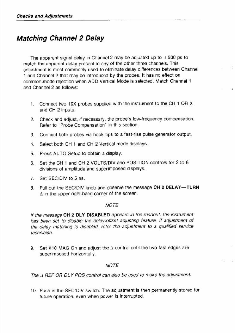
Matching Channel 2 Delay
The apparent signal delay in Channel 2 may be adjusted up to ± 500 ps to
match the apparent delay present in any of the other three channels. This
adjustment is most commonly used to eliminate delay differences between Channel
1 and Channel 2 that may be introduced by the probes. It has no effect on
common-mode rejection when ADD Vertical Mode is selected. Match Channel 1
andChannel 2
asfollows:
1. Connect two 10X probes supplied with the instrument to the CH 1 OR X
and CH 2 inputs.
2. Check and adjust, if necessary, the probe's low-frequency compensation.
Refer to "Probe Compensation" in this section.
3. Connect both probes via hook tips to a fast-rise pulse generator output.
4. Select both CH 1 and CH 2 Vertical mode displays.
5. Press AUTO Setup to obtain a display.
6. Set the CH t and CH 2 VOLTS/DIV and POSITION controls for 3 to 6
divisions of amplitude and superimposed displays.
7. Set SEC/DIV to 5 ns.
8. out the SEelDlV knob observe the message CH 2 DELAY-TURN
Checks and Adjustments

8/2/2019 2465A 2455A 2445A Operators Manual
http://slidepdf.com/reader/full/2465a-2455a-2445a-operators-manual 79/182
Amplitude Check
1. Obtain a display as described in alnitial Setup."
2. Set the VOLTS/DIV switch to tOO mV, the SEC/DIV switch to t ms, and
20 MHz BW LIMIT on.
3. Adjust the CH 1 POSITION control to center the display on the screen.
4. CHECK-Amplitude of the CALIBRATOR signal is between 3.88 and 4.12
divisions as measured on the center vertical graticule line.
S. Select and carefully superimpose the cursors on the high and low levels
of the waveform. C H E C K - ~ V readout is between 392 mV and 408 mY.
6. Repeat this procedure using the Channel 2 connector and controls.
Timing Check
The period of the CALIBRATOR signal automatically tracks the A SEC/DIV
setting within the range of 100 ms to 100 j,Ls. Within that SEC/DIV range, the
CALIBRATOR period is 200 ms to 200 ns, S cycles per 10 divisions of the A
Sweep. To quickly check the operation and calibration of the oscilloscope timing,
use the following procedure:

8/2/2019 2465A 2455A 2445A Operators Manual
http://slidepdf.com/reader/full/2465a-2455a-2445a-operators-manual 80/182
Controls, Connectors, and Indicators

8/2/2019 2465A 2455A 2445A Operators Manual
http://slidepdf.com/reader/full/2465a-2455a-2445a-operators-manual 81/182
Introduction
The following descriptions are intended to familiarize the operator with the
location and fUnction of the instrument's controls, connectors, and indicators.
All continuously variable controls, except FOCUS, TRACE ROTATION,
ASTIGMATISM, and SCALE ILLUMINATION have fine resolution for a portion oftheir rotation after each reversal. Continued rotation in the same direction gives
progressively coarser resolution.
Power And Display
Refer to Figure 5-1 for the location of items 1 through 10.
CD
CD
INTENSITY
Control
BEAM FINDButton
Adjusts the brightness of the waveform.
Limits the CRT deflection both vertically and horizontallyto within the graticule. Display intensity is not affected
by the BEAM FIND button.
Controls, Connectors, and Indicators
Various functions generate displays in the upper row.

8/2/2019 2465A 2455A 2445A Operators Manual
http://slidepdf.com/reader/full/2465a-2455a-2445a-operators-manual 82/182
CD ASTIG Control
SCALE ILLUM
Control
POWER
Switch
The most recently selected function displaces any
previous readout. If delta or delay readouts displacedisplays generated by the available TV enhancement
or crr, the TVor crr displays shift to the upper
left corner, in lieu of the trigger level readout.
Minimum intensity occurs at the control's midrange,
OFF position. Clockwise rotation from midrange
increases the intensity and enables all displays.Counterclockwise rotation from midrange increases
the intensity and disables the scale·factor and
control-status displays.
Adjusts the CRT beam shape to obtain a well-defined
display over the entire graticule area, in conjunction withthe FOCUS control. Once adjusted with a screwdriver, it
normally does not require readjustment.
Adjusts the level of graticule illumination.
Turns instrument power on and off. Press in for ON;
press again for OFF. An indicator in the switch shows
Controls, Connectors, and Indicators

8/2/2019 2465A 2455A 2445A Operators Manual
http://slidepdf.com/reader/full/2465a-2455a-2445a-operators-manual 83/182
7-_______p_9\_ _ _ _ _ _ _ _ _ ~ ~ ~ - - -Tektronix 2 4 6 5 A ' : ~ , ~ , : , ' / " 00 ' " '0"
: - - + - - 4 - - 1 - - 4 - - ~ - - ~ ~ - - ~ _ r _ _ i .>
Controls, Connectors, and Indicators

8/2/2019 2465A 2455A 2445A Operators Manual
http://slidepdf.com/reader/full/2465a-2455a-2445a-operators-manual 84/182
Setup and Vertical
Refer to Figure 5-2 for the location of items 11 through 17.
@ STEP/AUTO
Button
@
@
SAVE/HELP
Button
RECALL/HELP
Recalls the next step in a stored sequence of setups, if
the STEP indicator is illuminated. If the STEP indicator
is not illuminated, the oscilloscope automatically
establishes triggering and scales the waveform display
vertically and horizontally (AUTO).
Saves the current oscilloscope control settings in a
numbered setup when followed by one of the setup
number buttons, 1 through 8, which are also the Vertical
MODE buttons. Pushing the SAVE/HELP button
replaces the top and bottom rows of the normal readout
display with prompting and help messages. These help
messages may be cycled through by repeatedly pushing
the SAVE/HELP button. Additional setups are accessible
by using .J. and STEP. For operational information, see
the "Operation" section and Appendix B.
Restores previous oscilloscope control settings saved in
Controls, Connectors, and Indicators

8/2/2019 2465A 2455A 2445A Operators Manual
http://slidepdf.com/reader/full/2465a-2455a-2445a-operators-manual 85/182
SETUPSTEP;
0Y----
oSM l
r.:i\12 ~ " e ~ - - - D ®---------.:
AECAlC
13 HllP
D
14
A D ~ '.'.,1 ,IT , :H) ' l J\ \ ' ,
: A.T HW.IMI_'_---@
D ® ~ I D \ 9 ~ 16
6014·03
Figure 5 ~ 2 . SETUP and MODE buttons, and CH 1 and CH 2 POSITION controls.
Controls, Connectors, and Indicators
The algebraic sum of Channel 1 and Channel 2 is

8/2/2019 2465A 2455A 2445A Operators Manual
http://slidepdf.com/reader/full/2465a-2455a-2445a-operators-manual 86/182
@ CHOP/ALl
Button
CHOP
displayed when the Add display is selected. When
both Add and Invert displays are selected, the
waveform displayed is the difference between the
Channel 1 and Channel 2 signals. The INVERT
button also inverts the polarity of the signal output at
the CH 2 SIG OUT connector on the rear panel. At
the same time, the Channel 2 trigger-signal polarity is
inverted so that if CH 2 is selected as the TRIGGER
SOURCE, the displayed slope will agree with theTRIGGER SLOPE setting.
Selects the vertical display mode for multiple-channel
displays.
CHOP/ALT has no effect on the switching rate of X-Y
function displays. If more than one vertical display is
selected for X-Y, the display switches at 2.5 MHz.
When more than one channel is selected, the vertical
display switches sequentially through the selected
channels at the chop-switching rate.
When more than one channel is selected, if theSEC/DIV setting for the displayed sweep is in the
range of 20 /ls/div to 2 /ls/div, each channel is
20 MHz BW
Controls, Connectors, and Indicators
l imits the bandwidth of the vertical deflection system to
8/2/2019 2465A 2455A 2445A Operators Manual
http://slidepdf.com/reader/full/2465a-2455a-2445a-operators-manual 87/182
®LIMIT Button 20 MHz. Full vertical bandwidth is available when the
bandwidth limit function is off. Neither the triggersignals nor the output from the CH 2 SIG OUT
connector is affected by the 20 MHz BW LIMIT.
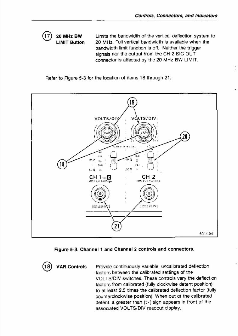
Refer to Figure 5·3 for the location of items 18 through 21.
",c
0 " 0, ; ~ l ' ; ~ U 'Mn co
mn cc
18"" 0 "C 0on cc so n m
CH 1 £J CH 2IMQ ISpF:S400Vp, lMn lopf:::4GU\·pk
Controls, Connectors, and Indicators
VOLTS/DIV Select vertical deflection factor settings in a 1-2-5

8/2/2019 2465A 2455A 2445A Operators Manual
http://slidepdf.com/reader/full/2465a-2455a-2445a-operators-manual 88/182
Switches
Input
Coupling
Buttons and
Indicators
1 MU AC
sequence with 11 positions. The VAR control must be in
the detent (funy clockwise) position to obtain a calibrated
deflection factor. Basic deflection factors are from 2 mV
per division to 5 mV per division. The switches can
rotate continuously, but have no effect beyond the
extreme settings. Deflection factors shown in the CRT
readout reflect actual deflection factors when Tektronix
attenuation-coded probes are connected to the inputs.
Select the method of coupling input signals to Channell
and Channel 2 and indicate the selection made. If the
upper Channell and Channel 2 Input Coupling buttons
are both pressed together, the instrument automatically
performs a dc balance of Channell and Channel 2
vertical circuit!"Y-
Input signal is capacitively coupled to the vertical
attenuator. The dc component of the input signal is
blocked. The low-frequency limit ( - 3 dB point) is
10Hz or less when using either a 1X probe or a
coaxial cable and is 1 Hz or less when using a
properly compensated lOX probe.
Only with the available Television!Video (TV)
1 Mil DC
Controls, Connectors, and Indicators
All frequency components of the input signal are

8/2/2019 2465A 2455A 2445A Operators Manual
http://slidepdf.com/reader/full/2465a-2455a-2445a-operators-manual 89/182
50 Il DC
CH 1 OR Xand CH 2
Input
coupled to the vertical. Input resistance is 1 MQ to
ground.
All frequency components of the input signal are
coupled to the vertical, with the input terminated by
50 Q to ground. If excessive signal is applied to
either the CH 1 or the CH 2 input connector while
50 n DC input coupling is selected, input coupling willrevert to 1 MQ GND and a CRT readout will indicate
the overloaded condition. Changing the input
coupling of the affected channel removes the
overload message.
Conduct external signalsto
the Channel 1 and Channel2 vertical inputs. A signal applied to the CH 1 OR X
connector provides the horizontal deflection for an X-V
display. Each connector includes a coding-ring contact
for Tektronix-coded probes.
Refer to Figure 5-4 for the location of items 22 through 26.
Controls, Connectors, and Indicators
CH 3 and Conduct external signals to the Channel 3 and Channel

8/2/2019 2465A 2455A 2445A Operators Manual
http://slidepdf.com/reader/full/2465a-2455a-2445a-operators-manual 90/182
@
@
@
CH 4 Input
Connectors
POSITION
Controls
VOLTS/DIV
Switches
CALIBRATOR
Connector
4 vertical inputs. Each connector includes a coding·ring
contact for Tektronix·coded probes. Input coupling from
these connectors is DC only. Channel 3 and Channel 4
are most useful as digital-signal and trigger-signal input
channels, given their limited choice of deflection factors.
Set vertical position of the Channel 3 and Channel 4
signal displays. The controls operate identically to the
Channel 2 POSITION control, but with less range ontheir associated traces.
Toggle between 0.1 V and 0.5 V per division deflection
factors for Channel 3 and Channel 4.
Provides a OA-V p-p square-wave into a 1 Mil load,
0.2-V p-p into a 50 Q dc-coupled load, or a-mA p-p intoa short circuit. The signal is useful for checking sweeps,
delay-times, and vertical deflection accuracies, as well
as compensating voltage probes and checking the
accuracy of current probes. The repetition rate of the
square wave changes with A-Sweep SEC/DIV changes.
From 100 ms per division to 100 ns per division, the A
Sweep of the instrument supplying the CALIBRATORsignal displays five cycles per 10 divisions. At 100 ms
per division and slower, the CALIBRATOR frequency is
Controls, Connectors, and Indicators
Horizontal

8/2/2019 2465A 2455A 2445A Operators Manual
http://slidepdf.com/reader/full/2465a-2455a-2445a-operators-manual 91/182
Refer to Figure 5-5 for the location of items 27 through 36.
Controls. Connectors, and Indicators
B SEC/DIY When the B Sweep is displayed, SEC/DIY selects
B-Sweep speeds in 22 calibrated steps from 50

8/2/2019 2465A 2455A 2445A Operators Manual
http://slidepdf.com/reader/full/2465a-2455a-2445a-operators-manual 92/182
ms/div to 5 ns/div in a 1-2-5 sequence (21 steps to
10 ns/div in the 2455A and 2445A).
Horizontal Display Mode Selection (PULL·INTEN TURN·ALT PUSH.B):
A When the SEC/DIV knob is in, the A Sweep is
displayed, unless the B Sweep has been displayedand the B Sec/Div setting remains faster than the A
Sec/Div setting. The exception is that Channel 1 is
displayed in the horizontal at the extreme
counterclockwise setting of SEC/DIV.
PULL·INTEN Pulling the SEC/DIY knob out while the A Sweep isdisplayed selects the Intensified horizontal display
mode and cancels the Delta Volts function if it is
active. The A-Sweep display intensifies during the B
Sweep. The B Sweep is not displayed, but it runs
either 100 times faster than the A Sweep or at 5 ns
per division, whichever is slower. In Alt horizontal
display mode, setting B Sec/Div equal to A Sec/Divalso selects the Intensified horizontal display mode.
Controls, Connectors, and Indicators
Pulling the SEC/DIV switch knob out at the fastest A

8/2/2019 2465A 2455A 2445A Operators Manual
http://slidepdf.com/reader/full/2465a-2455a-2445a-operators-manual 93/182
TURN-ALT
PUSH-B
Sec/Div rate selects thE' CH 2 delay offset
adjustment. The readout displays one of twomessages: -CH 2 DLY-TURN : '-or "CH 2 DLY
DISABLED.ff If the adjustment is enabled, the j ,
control or the . l REF control can adjust the apparent
delay between the Channel 1 signal and the Channel
2 signal. The adjustment range is sufficient to
compensate for propagation delay variations up to
± 500 ps. Adjusting the delay offset betweenChannel 1 and Channel 2 signals has no effect on
the common-mode rejection between Channel 1 and
Channel 2.
When the SEC/DIV knob is out, clockwise rotation
activates the Alternate Horizontal Display mode. TheAlt mode presents the intensified A-Sweep
alternating with the delayed B-Sweep. The position
of the intensified zone on the A-Sweep indicates the
time position of the B-Sweep, and the length of the
intensified zone indicates the B-Sweep duration. A
separate B-Sweep runs for each intensified zone.
In the Alt horizontal display mode, pushing in the
Controls, Connectors, and Indicators
TRACE SEP
Control
Positions the B trace downward from the A trace in Alt
horizontal display mode. In the B horizontal display

8/2/2019 2465A 2455A 2445A Operators Manual
http://slidepdf.com/reader/full/2465a-2455a-2445a-operators-manual 94/182
POSITION
Control
X10 MAG
Button
mode, with..lt or 1/j,t, TRACE SEP positions the trace
associated with the .:l control downward. Fully clockwise
rotation eliminates separation between the traces.
Horizontally positions the sweep displays.
Horizontally magnifies the portion of the sweep display
positioned at the center vertical graticule line by a factor
of 10. When in Alt or B horizontal display mode, only the
B·Sweep is affected.
Delay and Delta Controls
The :'V, :,t, and TRACKIINDEP buttons, with the:' REF OR DLY POS and:'
rotary controls, are used to make voltage, time, frequency, ratio, and phase
measurements. These controls also affect the SAVE and RECALL functions and
the CH 2 DLY matching function. With the available TV enhancement, j, also
serves as a line number selector and "FLD LINE #" nomenclature is added. With
the available CTT, j, REF and j, serve as menu selectors, with "MENU SELECT"
nomenclature added, and also as delaying·event·count controls. With the available
WR, they serve as word definition controls.
@ :'V Button Activates the Delta Volts measurement function and
@ :>t Button
Controls, Connectors, and Indicators
Activates the Delta Time measurement function and
cancels the!:J.V or 1/j,t measurement functions. When.lt

8/2/2019 2465A 2455A 2445A Operators Manual
http://slidepdf.com/reader/full/2465a-2455a-2445a-operators-manual 95/182
1/ >t
FUnction
is selected with Inten or Alt horizontal display modes,
two delay times are defined. When !:J.t is selected with
either A-Sweep or B-Sweep horizontal display, two
vertical cursors are established. One delay time or
cursor position is controlled by the :J. REF OR DL Y POS
control, and the other is controlled by the:J. control. The
CRT readout displays either the difference between the
two delay times or the equivalent time between the
vertical cursors.
If SEC/DIV VAR is not in the detent position, and either
the A-Sweep or the B-Sweep horizontal display mode is
selected, the CRT readout displays delta-time as a ratio,
where five divisions correspond to 100% ratio.
When .It is active, pressing the ..It button deactivates
the function.
Momentarily pressing the ..It and :J.V buttons
together activates the 1/Delta-Time function and
cancels any other Delta measurement function. Thewaveform display and the Delta controls operate the
same as for !It, but the readout shows the reciprocal
Controls, Connectors, and Indicators
OlY, j.V, .6.t,
and 1 { ~ t Each of these readouts includes a function name, a
signed, f l o a t i n g ~ p o i n t numeral, and the appropriate

8/2/2019 2465A 2455A 2445A Operators Manual
http://slidepdf.com/reader/full/2465a-2455a-2445a-operators-manual 96/182
Readoutsunit symbol. Numerals are displayed with larger sized
characters. A numeral immediately following ".6.
indicates which channel provides the delta voltage
scaling, the lowest numbered of the displayed
channels. Sweep Delay Time (DLY) is displayed for
the Inten, Alt, and B horizontal display modes when
none of the delta functions are selected. Except for
DLY, these readouts are enabled with ReadoutIntensity set for Scale Factors On or Scale Factors
Off.
A question mark appears after the .6.V function label
when the function applies to CH 3 or CH 4,
indicating poorer accuracy than is available with
CH 1 or CH 2.
A question mark appears in a DLY readout or in a .6.t
or 1/.6.t readout with a pair of sweep delays, when
one or both of the sweep delay settings is less than
1% of maximum delay (full scale) setting or when the
B-Trigger mode is TRIG AFT DlY (or, with CIT,
TRIG .6. DLV). With the CIT, these question marks
disappear when a direct measurement is complete. Aquestion mark also appears when the difference
betweeen the pair of delays in 1/.6.t is less than 1%
@ 1\ Control
Controls, Connectors, and Indicators
Positions the delta B-Sweep delay or time cursor
(dashed vertical line) when either.6.t or 1 / ~ t is active.

8/2/2019 2465A 2455A 2445A Operators Manual
http://slidepdf.com/reader/full/2465a-2455a-2445a-operators-manual 97/182
When V is active, the .6. control positions the delta
cursor (dashed horizontal line).
When a Save mode is active, .6. defines each character
in a setup name definition and each attribute field in a
sequence step definition.
With the availableCIT, .6.
selects items in theCIT
menuand defines characters in event-count definition displays.
With the WR, j . defines characters in word-definition
displays.
With the available TV enhancement, the control
nomenclature includes "FLO LINE # . ~ The control
selects specific line numbers within a video field fortriggering the A Sweep when trigger Coupling is set to
FLO 1, FLO 2, or alternate FLO 1-FLO 2. Possible line
numbers range from 1 to the maximum number of lines
per frame in the television signal. Rotating the control
clockwise increases the line number; rotating it
counterclockwise decreases the line number. Increasing
the line number above the number of lines in a field ordecreasing the number below the minimum automatically
sets the line number to the minimum or the maximum in
Controls, Connectors, and Indicators
TRACK/INDEP
Button
Selects either the Tracking or Independent mode for the
1\ REF OR DL Y pas control. In the Tracking mode,

8/2/2019 2465A 2455A 2445A Operators Manual
http://slidepdf.com/reader/full/2465a-2455a-2445a-operators-manual 98/182
rotating the .l REF OR DLY pas control changes both
delays or both cursors equally until the limit of either is
reached.
In the Indep mode, 1\ REF OR DL Y pas affects only the
reference delay or cursor. In either Tracking or
Independent mode, the .l control moves only the 6.
cursor.
Refer to Figure 5-6 for the location of items 37 through 46.
"J'Il_I'1 ' / [HI cc
AL '0 'c N:IS[
A·Trigger Modes:
Controls, Connectors, and Indicators

8/2/2019 2465A 2455A 2445A Operators Manual
http://slidepdf.com/reader/full/2465a-2455a-2445a-operators-manual 99/182
AUTO LVL Automatically establishes the trigger level on atriggering signal and free runs the sweep in the
absence of a triggering signal.
In Auto Lvi mode, LEVEL covers the range between
the positive and negative peaks of repetitive
triggering signals. If the triggering signal amplitudechanges, the trigger level does not change unless a
trigger is no longer produced at the established level.
The signal peaks are measured and the trigger level
is redefined when triggering ceases, when the LEVEL
control is turned to either extreme, or when the
upper MODE button is pressed. If the LEVEL control
is set near either end position, the trigger level is setnear the corresponding signal peak. If LEVEL is inthe midrange between either end, the trigger level set
by AUTO LVL is near the midpoint between the
trigger signal peaks. When INIT@50% is pressed,
the trigger level is set near the midpoint of the signal,
regardless of the setting of LEVEL. The established
trigger level remains in effect when switching to Autotrigger mode.
Controls, Connectors, snd Indicstors
NORM Sweep is triggered and runs when an adequate
triggering signal is applied. In the absence of an

8/2/2019 2465A 2455A 2445A Operators Manual
http://slidepdf.com/reader/full/2465a-2455a-2445a-operators-manual 100/182
SGl SEa
B·Trigger Modes:
MENU
adequate triggering signal, the A Sweep does not
run, except when the input coupling of the trigger
source channel is set to GND. If the selected source
is Vert, and the Add vertical display is selected, the
A Sweep free runs if Channel 1 and Channel 2 input
coupling are both set to GND.
When armed by pushing the lower MODE button, the
sweep runs once for each of the traces defined by
the following controls: Vertical MODE, A and B
SEC/DIV, and Ilt or 1/D.t. Each sweep requires a
distinct A-Sweep triggering eventt? !q The READY
indicator remains illuminated until the final trace in
the sequence is completed. At the end of the displaysequence, scale-illumination flashes and the readout
display is written once to present the scale factors
and other readout data.
Only with the available CIT, the Menu indicator
lights when a menu is displayed and when the trigger
TRIG'" DLY
Controls, Connectors, and Indicators
Only with the available crr, and with A.t or 1/llt
active, the Trigger Slope and Level for the II delay

8/2/2019 2465A 2455A 2445A Operators Manual
http://slidepdf.com/reader/full/2465a-2455a-2445a-operators-manual 101/182
SOURCE
Buttons and
Indicators
VERT
canbe
set separately from those for the REFerencedelay. If both TRIG AFT DLY and TRIG'" DLY
indicators are on, the B ~ T r i g g e r Slope and Level are
common for the two delays. TRIG oil DLY should
normally be used with VERT trigger source for
B Trigger. Pressing the lower trigger Mode button
alternates between TRIG AFT DLY and TRIG'" DLY
and the controls are alternately directed to the twotriggers.
Select the trigger-signal source for either A Sweep or B
Sweep.
The sweep triggers on the displayed channel when
only one channel is selected. If multiple vertical
displays are selected, both the trigger Mode and the
Chop/Alt selection affect the triggering source. With
Alt vertical mode and with A-Trigger modes other
than Auto Lvi, each displayed channel in turn
provides the triggering signal and the respective LEDindicator for each displayed channel is illuminated.
With Auto Lvi trigger mode or with Chop vertical
Controls, Connectors, and Indicators
NOISE REJ All frequency components of the input signal are
coupled to the trigger. This coupling improves trigger

8/2/2019 2465A 2455A 2445A Operators Manual
http://slidepdf.com/reader/full/2465a-2455a-2445a-operators-manual 102/182
HF REJ
LF REJ
AC
stability with signals accompanied by low-level noise.
Attenuates high-frequency triggering-signal
components above 50 kHz. This coupling eliminates
radio-frequency interference and high-frequency
noise components from the signal applied to the
trigger. It allows triggering on the low-frequency
components of a complex waveform.
Signals are capacitively coupled, blocking the dc
component of the triggering signal and attenuating
the low-frequency signal components below 50 kHz.
This coupling allows triggering on the high-frequency
components of a complex waveform.
Signals are capacitively coupled. Frequency
components below 60 Hz are attenuated, and the dc
component of the input signal is blocked. This
coupling worksfor
signals that are superimposedon
slowly changing dc voltages. This method will work
for most signals when trigger-level readout is not
ALT
Controls, Connectors, snd Indicstors
The A Sweep alternately triggers on the same
selected line in both TV fields. Both the FLD 1 and

8/2/2019 2465A 2455A 2445A Operators Manual
http://slidepdf.com/reader/full/2465a-2455a-2445a-operators-manual 103/182
A/B
TRIG (orA/B/MENU)
Button
the FLD 2 indicators light. NORM trigger mode isautomatically selected.
With CHOP vertical mode, all channels are displayed
with both the FLD 1 and the FLD 2 triggers.
With Alt vertical mode and more than one channel
displayed, field 1of
the video signal triggers thesweep with the first displayed channel and field 2
triggers the sweep with the next displayed channel.
With more than two channels, each additional
channel is displayed with triggers from both fields.
The MODE, SOURCE, COUPLING, SLOPE, LEVEL,and INIT@50% controls are normally directed to the
A Trigger. They are directed to the B Trigger with Inton,
Alt, or B-Sweep horizontal displays, if B mode is TRIG
AFT DLY (or, with the CIT, TRIG ,:\ DLV). The trigger
controls are directed to the opposite trigger while the
AlB TRIG (or, with the CIT, A/B/MENU) button is
pressed. With Inten, Alt,or
B-Sweep horizontal displays,and with B-Trigger mode set to RUN AFT DLY or with
A-Trigger mode set to Sgl Seq, the trigger controls are
Controls, Connectors, and Indicators
@ SLOPE Button
and Indicators
Determines whether the A Trigger or 8 Trigger respond
to the positive-going or the negative-going slope of a

8/2/2019 2465A 2455A 2445A Operators Manual
http://slidepdf.com/reader/full/2465a-2455a-2445a-operators-manual 104/182
@
@
@
ASWP
TRIG'D
Indicator
READY
Indicator
HOLDOFF
Control
signal. With the availableTV
enhancement, Slopeselects positive or negative sync polarity. With the
available Crr, in Logic Trigger modes, Slope determines
whether the high (+) or low ( - ) state of the signal is the
true input to the logic function.
Illuminates when the A Sweepis
triggered. Itextinguishes a short time after completion of a sweep
unless a triggering signal is received.
Illuminates when Sgl Seq mode is selected and the ASweep is armed and waiting for a triggering event to
occur. It extinguishes following the completion of all the
traces selected for the Sgl Seq display.
Varies the time from the end of an A Sweep to enabling
the next sweep to be initiated by the triggering signal.
This control can be set to stabilize some aperiodic
signals. In the a ENDS A position (fully clockwise)
trigger holdoff time is minimum, and A Sweep terminates
immediately at the end of the 8 Sweep. This enables the
Controls, Connectors, and Indicators
Rear Panel

8/2/2019 2465A 2455A 2445A Operators Manual
http://slidepdf.com/reader/full/2465a-2455a-2445a-operators-manual 105/182
Refer to Figure 5-7 for the location of items 47 through 57.
®
@
@
®
@
A GATE OUT
and B GATE
OUT
Connectors
Line Voltage
Selector
Switch
EXT Z·AXIS
IN Connector
Fuse Holder
Detachable
Power Cord
Provide TIL-compatible, positive-going gate signals that
are HI during their respective sweeps and LO while the
sweep is not running. When the A SEC/OIV switch is set
to 5 ns per division, a gate signal is present at both theA GATE OUT and the B GATE OUT connectors.
Selects either 115 V or 230 V nominal ac-power-source
voltage.
Provides an input for external signals to modulate the
display intensity.
Contains the ac power-source fuse.
Connects the ac power source to the instrument.
Controls, Connectors, and Indicators
@ Word Connects the 17 -Bit Word Recognizer Probe to the
Recognizer instrument, only with the available WR (Option 09), or
Probe supplies conditioned dc voltages to active probes, only

8/2/2019 2465A 2455A 2445A Operators Manual
http://slidepdf.com/reader/full/2465a-2455a-2445a-operators-manual 106/182
Connector or with Option 11.
Probe Power
Connector
@ WORD Provides a LSTTL-compatible, positive-going pulse
RECOG OUT when the Word Recognizer detects the selected word,
Connector or only with the available WR (Option 09), or supplies
Probe Power conditioned dc voltages to active probes, only withConnector Option 11.
® GPIB Provides the IEEE Std 488-1978 compatible electrical
Connector and mechanical connection to the GPIB.
Controls, Connectors, and Indicstors
DMM

8/2/2019 2465A 2455A 2445A Operators Manual
http://slidepdf.com/reader/full/2465a-2455a-2445a-operators-manual 107/182
All OMM controls are momentary push buttons. The buttons alternately select
and deselect functions. Refer to Figure 5-8 for the location of items 58 through 70.
@ RANGE
Buttons
AUTO
UP and
DOWN
Select full-scale ranges for measurements.
Selects autorange. The measurement range changes
as necessary to maintain the reading within 9% to
100% of full scale. Autoranging is automatically
selected each time a new measurement function is
selected. If autoranging is active, pressing AUTO
deselects autoranging. When the button is pressed
again, autoranging returns.
When a measurement range changes, the displayblanks momentarily. If a measurement exceeds a
manually selected range or the highest range with
autoranging, "OVER" is displayed in the readout.
Change the measurement range. In autorange mode,
pressing either button disables autoranging andselects the next range above or below the present
range. Pressing the UP button at the highest range
Controls, Connectors, and Indicators
dBm Displays ac rms voltage measurements as the log of
the ratio of the input voltage to a 1 mW reference at
600 n. Readings equal 20X 10g(VinputNref)' where

8/2/2019 2465A 2455A 2445A Operators Manual
http://slidepdf.com/reader/full/2465a-2455a-2445a-operators-manual 108/182
@ CONT
@ HIIl/LO Il
Hill
Vinput is the input voltage and Vref is 0.7746 V. With
zero input, the readout displays "OVER."
Selects or deselects continuity. If the resistance between
the probes is less than 10 n, the instrument produces an
audible tone. The readout shows either "SHORT <10 fl" or "OPEN> 10 n." The tone responds to
continuity within about 100 ms.
Continuity operation is not affected by AUTO, UP,
DOWN, HOLD, SMOOTH, MIN/MAX DISPLAY,
MIN/MAX RESET, REF DISPLAY, or REF SET.
Selects or deselects resjstance measurement.
Measures resistance within 2 k, 20 k, 200 k, 2 M,
and 20 M n ranges. At full scale, 2 V appears across
the test leads, which will bias a silicon semiconductor
junction to forward conduction.
@ 'C/ 'F
Controls, Connectors, and Indicators
Selects or deselects temperature measurement. If a
temperature probe is not connected to the input jacks,
the readout shows "ATTACH TEMP PROBE."

8/2/2019 2465A 2455A 2445A Operators Manual
http://slidepdf.com/reader/full/2465a-2455a-2445a-operators-manual 109/182
'C
'F
@ SHIFT
Measures temperature in Celsius degrees.
Measures temperature in Fahrenheit degrees.
Selects the secondary functions of the other DMM
buttons. Primary functions are indicated on the panel
above the DMM buttons and secondary functions are
indicated below. Pressing SHIFT while shift is pending
cancels the shift prefix. A pending shift prefix will clear
automatically if another DMM button is not pressed
within 10 seconds. While the shift prefix is pending,
"SHIFT" appears in the readout.
@ HOLD/SMOOTH Changes the display mode.
HOLD "Freezes" the display, which also shows "HLD."
Display updating resumes when any DMM button is
pressed.
Controls, Connectors, and Indicators
MINIMAX
RESET
Initializes the minimum and maximum values when
the next measurement is made. Selecting a new
DMM function also resets the minimum and

8/2/2019 2465A 2455A 2445A Operators Manual
http://slidepdf.com/reader/full/2465a-2455a-2445a-operators-manual 110/182
REF DISPLAY
IREF SET
REF
DISPLAY
REF SET
maximum values.
Displays or sets a reference measurement.
Shows the present reference value. If no reference
has been set, the display will show O.
Initializes the reference value to the present display.
All subsequent measurements will be displayed with
this reference value subtracted from them. If no
measurement is displayed, or if the present
measurement is out of range, REF SET has no
effect.
When a measurement has a reference value
subtracted from it, the display includes a .J. symbol.
With dBV or dBm, the reference takes the place of
Vref
. Selecting a new DMM function or turning off
power clears the reference. The reference is retained
if another instrument function, such as .lt, displaces
Controls, Connectors, and Indicators
DMM Displays

8/2/2019 2465A 2455A 2445A Operators Manual
http://slidepdf.com/reader/full/2465a-2455a-2445a-operators-manual 111/182
Large digits indicate measured values. Parameter units and other textexcept "OVER" are displayed as smaller letters and digits. The following
examples show various display formats:
DC Voltage
SMOOTH
Using a Reference Value
Reference Display
Minimum Display
Maximum Display(with Reference)
Continuity Display
Over-Range Display
15.693 V DC
1 4356 A DC 1641
. l 0.9861 A DC
1.3461 V D C ~ R E F
0.5201 V A C ~ M I N
. l 0.8293 V DC MAX
OPEN
SHORT
OVER
> 10 n
< 10 n

8/2/2019 2465A 2455A 2445A Operators Manual
http://slidepdf.com/reader/full/2465a-2455a-2445a-operators-manual 112/182
Performance Characteristics
Performance Conditions

8/2/2019 2465A 2455A 2445A Operators Manual
http://slidepdf.com/reader/full/2465a-2455a-2445a-operators-manual 113/182
The following electrical characteristics (Tables 6-1 through 6-6) are valid for the
instrument when it has been adjusted at an ambient temperature between +20°C
and +30°C, has had a warm-up period of at least 20 minutes, and is operating at
an ambient temperature between -15°C and +55°C (unless otherwise noted).
Items listed in the "Performance Requirements" column define the measurementcapabilities of the instruments. Supplementary measurement conditions may also
be listed in the "Performance Requirement" column.
Mechanical characteristics are listed in Table 6-7.
Environmental characteristics are given in Table 6-8. The oscilloscope meets the
environmental requirements of MIL-T-28800C for Type III, Class 3, Style C
equipment, with the humidity and temperature requirements defined in paragraphs
3.9.2.2, 3.9.2.3, and 3.9.2.4.
Performance Characteristics

8/2/2019 2465A 2455A 2445A Operators Manual
http://slidepdf.com/reader/full/2465a-2455a-2445a-operators-manual 114/182
Table 6-1
2465A/2455A/2445A Electrical Characteristics
Characteristics Performance Requirements
VERTICAL DEFLECTION SYSTEM-CHANNEL 1 AND CHANNEL 2
Deflection Factor
Range 2 mV/division to S V/division in a 1-2-5
sequence of 11 steps.
Accuracy 1 Mn input, non inverted.
+lSoC to ...... 3SoC
On-Graticule Accuracy Within ± 2% at any VOL TS/DIV setting for a
four or five-division signal centered on the
screen.
V Accuracy (using ±(1.25% of reading +0.03 div + signal
cursors over entire aberrations).
graticule area)
-15 'C to +15'C and Add ± 2% of reading.
Performance Characteristics
Table 6-1 (cont)
2465A/2455A/2445A Electrical Characteristics

8/2/2019 2465A 2455A 2445A Operators Manual
http://slidepdf.com/reader/full/2465a-2455a-2445a-operators-manual 115/182
Characteristics Performance Requirements
Frequency Response Bandwidth is measured with a leveled, low
distortion, 50-0 source, sine-wave generator,
terminated in 50 o. The reference signal
amplitude is set at the lesser of 6 divisions or
the maximum leveled amplitude.
Bandwidth with probe is checked using a
probe-tip-to-GR (017-OS20-00) termination
adapter.
Bandwidth with external termination is checkedusing a BNC 50-0 feed through terminator
(011 -0049-01).
-3 dB Bandwidth Using standard accessory probe or internal
50-0 termination.
2465A+1S'C to +3S'C Dc to 3S0 MHz.
Performance Characteristics
Table 6-1 (cant)
2465A/2455A/2445A Electrical Characteristics

8/2/2019 2465A 2455A 2445A Operators Manual
http://slidepdf.com/reader/full/2465a-2455a-2445a-operators-manual 116/182
Characteristics Performance Requirements
AC Coupled, Lower -3 dB 10Hz or less.
Frequency
With Standard Accessory Probe 1 Hz or less.
Step Response Rise Time Calculated from Tr=0.35/BW.
2465A ",;1 ns .
2455A .",;1.4 ns.
2445A .",;2.33 ns.
Channel Isolation ;?o100: 1 attenuation of deselected channel at
100 MHz; ;?o50:1 at 350 MHz, for an eight-
division input signal from 2 mV per division to
500 mV per division, with equal VOL TS/DIV
settings on both channels.
Displayed Channel 2 Signal Delay Adjustable through a range of at least - 500 ps
with Respect to Channell Signal to +500 ps.
Input Rand C (1 MIl)
Performance Characteristics
Table 6-1 (cont)
2465A/2455A/2445A Electrical Characteristics

8/2/2019 2465A 2455A 2445A Operators Manual
http://slidepdf.com/reader/full/2465a-2455a-2445a-operators-manual 117/182
Characteristics
Cascaded Operation
Deflection Factor
CMRR (ADD Mode with Channel 2
inverted)
Performance Requirements
Channel 2 Vertical Signal Output into Channel 1
input; DC coupled using a 50 n RG-58C/U
coaxial cable, terminated in 50 { l at the
Channel 1 input. Channel 1 and Channel 2
VOLTS/DIV set at 2 mV and Bandwidth LimitOn.
400 per division ± 10%.
At least 20:1 at 50 MHz for common-mode
signals of eight divisions or less, with VAR
VOL TS/DIV control adjusted for best CMRR at50 kHz, at any VOLTS/DIV setting.
VERTICAL DEFLECTION SYSTEM-CHANNEL 3 AND CHANNEL 4
Deflection Factors
Values 100 mV and 500 mV per division.
Accuracy Within ± 10'%.
Frequency Response Bandwidth is measured with a leveled, low
Performance Characteristics
Table 6-1 (cant)
246SA/24SSA/244SA Electrical Characteristics

8/2/2019 2465A 2455A 2445A Operators Manual
http://slidepdf.com/reader/full/2465a-2455a-2445a-operators-manual 118/182
Characteristics Performance Requirements
-4.7 dB Bandwidth Using 50-0 external termination.
2465A
+15'C to +35'C Dc to 350 MHz.
-15 'C to +15'C Dc to 300 MHz.
and -r-35°C to +55°C
2455A
+15'C to +35'C Dc to 250 MHz.
-15 'C to +15'C Dc to 200 MHz.
and +35'C to +55'C
2445A Dc to 150 MHz.
Step Response Rise Time Calculated from Tr=0.35/BW.
2465A ns.2455A ~ 1 . 4 n s .
Performance Characteristics
Table 6-1 (cont)
2465A/2455A/2445A Electrical Characteristics

8/2/2019 2465A 2455A 2445A Operators Manual
http://slidepdf.com/reader/full/2465a-2455a-2445a-operators-manual 119/182
CharacteristiCs
Vertical Signal Delay
Chopped Mode Switching Rate
Minimum p_p Signal Amplitude for
Stable Triggering from Channel 1or
Channel 2 Source
Performance Requirements
At least 30 ns of the sweep is displayed before
the triggering event is displayed at any SECJDIV
~ 1 0 ns/div. At 5 nsJdiv, at least 10 ns of the
sweep is displayed before the triggering event.
With displayed SEC/DIV in the 20 #s to 2 #s/div
range, the switching rate is 2.5 MHz ± 0.2%.
Otherwise, the switching rate is 1 MHz ± 0.2%.
The display cycle rate equals the chop switching
rate divided by the number of channels
displayed. The chop switching rate is modulatedslightly to minimize waveform breaks with
repetitive signals.
TRIGGERING
Performance Characteristics
Table 6-1 (cont)
2465A/2455A/2445A Electrical Characteristics

8/2/2019 2465A 2455A 2445A Operators Manual
http://slidepdf.com/reader/full/2465a-2455a-2445a-operators-manual 120/182
Characteristics Performance Requirements
AC Coupled 0.35 division from 60 Hz to 50 MHz; increasing
to 1.5 divisions at 250 MHz. Attenuates signals
below 60 Hz.
HF REJ Coupled 0.5 division from dc to 30 kHz.
LF REJ Coupled 0.50 division from 80 kHz to 50 MHz;
increasing to 1.5 divisions at 250 MHz.
Minimum P-P Signal Amplitude for Add 0.5 division to CH 1 or CH 2 requirement at
Stable Triggering from ADD Source 300 MHz and 500 MHz for 2465A and 2455A.
Minimum P-P Signal Amplitude for 0.5 X CH 1 or CH 2 requirement.
Stable Triggering from CH 3 or
CH 4 Source
Minimum P-P Signal Amplitude for Add 1 division to the single-ehannel source
Stable Triggering from Composite, specification.
Multiple Channel Source, ALT
Vertical Mode
Checked at 50 mV per division.
Performance Characteristics
Table 6-1 (cant)
2465A/2455A/2445A Electrical Characteristics

8/2/2019 2465A 2455A 2445A Operators Manual
http://slidepdf.com/reader/full/2465a-2455a-2445a-operators-manual 121/182
Characteristics Performance Requirements
LEVEL Readout Accuracy For triggering signals with transition times
greater than 20 ns.
CH 1 or CH 2 SOURCE+15°C to +35°C Within ± [3% of setting + 3% of p-p signal +
0.2 division + 0.5 mV + (0.5 mV X probe
attenuation factor)] with Vertical Input at 1 Mn
DC, CH 2 Source Not Inverted, and Trigger DC
Coupled.
-15°C to +35°C and Add 1.5 mV X probe attenuation to +15°C to+35°C to +55°C +35°C specification.
50 Q Input Add ± 1% to 1 Mn input specification.
CH 2 Inverted Add ± 1% of setting to non-inverted
specification.
NOISE REJ Coupled Add ± 0.6 division to DC Coupledspecifications.
PerformBnce ChBrBcteristics
Table 6-1 (conI)
2465A/2455A/2445A Electrical Characteristics

8/2/2019 2465A 2455A 2445A Operators Manual
http://slidepdf.com/reader/full/2465a-2455a-2445a-operators-manual 122/182
Characteristics
AUTO LVL Mode Trigger
Acquisition Time
Trigger Holdoff
Minimum
Variable
SLOPE Selection
Performance Requirements
Eight to 100 times the AUTO LVL Mode
maximum triggering signal period, depending on
the triggering signal period and waveform.
The greater of the A-SEC/DIV setting value or
2 }.lS, within +33% to -10%, except 1 }.lS at
5 ns/div.
Increases trigger holdoff time to 10 to 25 times
the minimum holdoff.
Conforms to trigger-source waveform or acpower-source waveform.
HORIZONTAL DEFLECTION SYSTEM
A Sweep Time Base Range
2465A 500 ms/div to 5 ns/div in a 1-2-5 sequence of
25 steps. X10 MAG extends maximum sweeprate to 500 ps/div.
Performance Characteristics
Table 6-1 (cont)
2465A/2455A/2445A Electrical Characteristics

8/2/2019 2465A 2455A 2445A Operators Manual
http://slidepdf.com/reader/full/2465a-2455a-2445a-operators-manual 123/182
Characteristics Performance Requirements
Xl0 MAG Accuracy Add ± 0.5% of time interval to unmagnified
Sweep and ,j,t Cursors specifications. Exclude
the first 0.5 division after the sweep starts (the
first 0.5% of the full 100 division sweep).
500 ms or 200 ms/div Timing Add ± 0.5% of interval to specifications for A
Accuracy (A Sweep only) SEC/DIV at 100 ms or faster.
SEC/DIV VAR Timing Accuracy Add 2% of time interval to sweep accuracy
specifications when VAR is out of detent.
Timing Accuracy (-15°C to +15°C Add ± 0.2% of time interval to all .It and delay
and +35'C to +55'C) specifications. Add ± 0.5% of interval to sweep
accuracy specification .
.}.t Readout Resolution
2465A Greater of either lOps or 0.025% of full scale.
2455A, 2445A Greater of either 20 ps or 0.25% of full scale.
.}.t Range ± 10 times A-SEC/DIV setting with Cursors,
Performance Characteristics
Table 6-1 (cont)
2465A/2455A/2445A Electrical Characteristics

8/2/2019 2465A 2455A 2445A Operators Manual
http://slidepdf.com/reader/full/2465a-2455a-2445a-operators-manual 124/182
Characteristics Performance Requirements
X-V Operation
X-Axis Deflection Factor Range, Same as Channell.
Variable, and Input
Characteristics
Deflection Factor Accuracy Same as Channell.
X-Axis Bandwidth Dc to 3 MHz.
Phase Difference Between X and ..;;;1 0 from dc to 1 MHz; ..;;;3 0 from 1 MHz to
Y with BW Limit Off 2 MHz.
X-Axis Low-frequency Linearity 0.1 division or less compression or expansion of
a two-division, center-screen signal when
positioned within the graticule area.
Cursor Position Range
DISPLAY
Performance Characteristics
Table 6·1 (cont)

8/2/2019 2465A 2455A 2445A Operators Manual
http://slidepdf.com/reader/full/2465a-2455a-2445a-operators-manual 125/182
2465A/2455A/2445A Electrical Characteristics
Characteristics
Sensitivity
De to 2 MHz
2 MHz to 20 MHz
Input Resistance
Maximum Input Voltage
CALIBRATOR
Output Voltage and Current
Performance Requirements
Z·AXIS INPUT
Positive voltage decreases intensity; + 2 V
blanks a maximum intensity trace.
+2 V modulates a normal intensity trace.
9 kn +10%.
± 25 V peak; 25 V p-p ac at 10kHz or less.
SIGNAL OUTPUTS
With A SEC/DIV set to 1 ms.
0.4 V ± 1% into a 1-Mn load, 0.2 V ± 1.5% into
a so-n load, or 8 mA ± 1.S% into a short circuit.

8/2/2019 2465A 2455A 2445A Operators Manual
http://slidepdf.com/reader/full/2465a-2455a-2445a-operators-manual 126/182

8/2/2019 2465A 2455A 2445A Operators Manual
http://slidepdf.com/reader/full/2465a-2455a-2445a-operators-manual 127/182
Performance Characteristics
Table 6-2 (cont)
Option 01 (DMM) Electrical Characteristics
Characteristics

8/2/2019 2465A 2455A 2445A Operators Manual
http://slidepdf.com/reader/full/2465a-2455a-2445a-operators-manual 128/182
Performance Requirements
AC VOLTS
Accuracies by Range Crest Factor ~ 4 . +18"C to +28"C
200 mV to 200 V Input signal between 5% and 100% of full scale.
40 Hz to 10 kHz ±(0.6% of reading + 0.1% of full scale).
20 Hz to 40 Hz and ± (1 % of reading + 0.1 % of full scale).
10 kHz to 20 kHz
20 kHz to 100 kHz ±(5% of reading
+0.1% of full scale).
500 V Input signal between 100 V and 500 V.
40 Hz to 10 kHz + (0.6% of reading + 0.2% of full scale).
20 Hz to 40 Hz and ±(1% of reading + 0.2% of full scale).
10kHz to 20 kHz
20 kHz to 100 kHz + (5% of reading + 0.2% of full scale).
-15"C to f18"C and +28"C
Performance Characteristics
Table 6·2 (cant)
Option 01 (OMM) Electrical Characteristics

8/2/2019 2465A 2455A 2445A Operators Manual
http://slidepdf.com/reader/full/2465a-2455a-2445a-operators-manual 129/182
Characteristics
Response Time
Manual Range
Auto Range
Input Impedance
dBV, dBm
Accuracy
Resolution
Accuracies by Range
+18'C to +28'C
2kOt02MO
20 M!l
Performance Requirements
Less than 2 seconds.
Less than 3 seconds.1 Mn ± 1% in parallel with less than 100 pF.
dB readings are calculated from AC VOLTS
measurements.
0.01 dB.
HI OHMS
± (0.1 % of reading
+0.01 % of full scale).
± (0.5% of reading + 0.01 % of full scale).
Performance Characteristics
Table 6·2 (cant)
Option 01 (OMM) Electrical Characteristics

8/2/2019 2465A 2455A 2445A Operators Manual
http://slidepdf.com/reader/full/2465a-2455a-2445a-operators-manual 130/182
Characteristics Performance Requirements
Measuring Current by Range
2 kO Approximately 1 mAo
20 kO Approximately 0.1 mAo
200 kO Approximately 10 JlA.
2 MO Approximately 1 11A.
20 Mn Approximately 0.1 p,A.
Response Time
2kQt02Mn
Manual Range Less than 1 second.
Auto Range Less than 2 seconds.
20 MQ Range Less than 5 seconds.
Reading Rate by Range
2 kO to 2 Mn Approximately 3 per second.
Performance Characteristics
Table 6-2 (cant)
Option 01 (OMM) Electrical Characteristics

8/2/2019 2465A 2455A 2445A Operators Manual
http://slidepdf.com/reader/full/2465a-2455a-2445a-operators-manual 131/182
Characteristics Performance Requirements
LO OHMS
Accuracies by Range
+18"C to +28"C
200 n ± (0.1 ''10 of reading + 0.1 % of full scale).
2 kn to 200 kn ± (0.1 % of reading + 0.01 % of full scale).
2 Mn ± (0.25% of reading + 0.01 % of full scale).
-15"Cto
+18"C
and+28"C
to +55"C
200 n to 20 kn Add ± (0.01 % of reading + 0.001 % of full
scale)I"C above 28"C or below 18"C.
200 kn Add ± (0.01 % of reading + 0.001 % of full
scale)jOC above 28°C or below 18°C ±2% of
reading per 10% relative humidity above 70%relative humidity.
Performance Characteristics
Table 6-2 (cant)Option 01 (DMM) Electrical Characteristics

8/2/2019 2465A 2455A 2445A Operators Manual
http://slidepdf.com/reader/full/2465a-2455a-2445a-operators-manual 132/182
Characteristics Performance Requirements
AMPS
DC Accuracy
+18'C to +28'C ± (0.1 % of reading + 0.02% of full scale).
-15 'C to +18'C and +28'C ± (0.15% of reading + 0.06% of full scale).
to +55'C
AC Accuracy 20 Hz to 10kHz sinusoidal waveform.
+18'C to +28'C ±(0.6% of reading + 0.1% of full scale).
-15 'C to +18'C and +28'C ± (0.7% of reading + 0.15% of full scale).
to +55'C
Response Time
Manual Range Less than 1 second.
Performance Characteristics
Table 6-2 (cant)Option 01 (DMM) Electrical Characteristics

8/2/2019 2465A 2455A 2445A Operators Manual
http://slidepdf.com/reader/full/2465a-2455a-2445a-operators-manual 133/182
Characteristics Performance Requirements
CONTINUITY
Response Time Approximately 0.1 second.
Threshold Resistance 10n± ln .
TEMPERATURE
Accuracy
+18°C to +28°C AmbientTemperature
~ 1 5 ° C to +18°C and +28°C
to +55"C Ambient Temperature
Probe Tip Measurement Range
Resolution
± (2% of reading + 1.5"C).
±(2% of reading + 2.0"C).
~ 6 2 " C to +230"C in one range.
0.1"C or 0.1"F.
Performance Conditions
Table 6-3
Option 05 (TV) Electrical Characteristics

8/2/2019 2465A 2455A 2445A Operators Manual
http://slidepdf.com/reader/full/2465a-2455a-2445a-operators-manual 134/182
Characteristics Performance Requirements
VERTICAL DEFLECTION SYSTEM-CHANNEL 1 AND CHANNEL 2
Frequency Response For VOL TS/DIV settings between 5 mV and
0.2 V with VAR control in calibrated detent.
Five-division, 50-kHz reference signal from a
50-0 system. With external 50-n termination on
1 Mn input.
Full Bandwidth
50 kHz to 5 MHz Within ± 1%.
>5 MHz to 10 MHz Within +1%, -2%.
>10 MHz to 30 MHz Within +2%, -3%.
Bandwidth Limit
50 kHz to 5 MHz Within +1%, -4%.
Square Wave Flatness With fast-rise step (rise time 1 ns), 1 Mn dc
Performance Characteristics
Table 6-3 (cont)
Option 05 (TV) Electrical Characteristics

8/2/2019 2465A 2455A 2445A Operators Manual
http://slidepdf.com/reader/full/2465a-2455a-2445a-operators-manual 135/182
Characteristics Performance Requirements
TV (Back-Porch) Clamp (CH 2 only) For VOLTS/DIV settings between 5 mV and
0.2 V with VAR control in calibrated detent.
Six-division reference signal.
60 Hz Attenuation ""S dB.
Back-Porch Reference Within 1.0 division of ground reference.
TRIGGERING
Sync Separation Stable video rejection and sync separation fromsync-positive or sync-negative composite video,
525 to 1280 lines, 50 Hz or 60 Hz, interlaced or
noninterlaced systems.
For noninterlaced scan systems, the video
signal source must start and end with full lines
of video for correct line identification in the fieldtrigger modes.
Performance Characteristics
Table 6-4
Option 06 (CIT T) Electrical Characteristics
Characteristics Performance Requirements

8/2/2019 2465A 2455A 2445A Operators Manual
http://slidepdf.com/reader/full/2465a-2455a-2445a-operators-manual 136/182
SIGNAL INPUT
With DC Coupling of A Trigger and B Trigger.
Maximum Input Frequency for ;;.150 MHz.
Count and Delay by Events
Minimum Width of High or Low ~ 3 . 3 ns.
State of Input Signal for Count and
Delay by Events
Sensitivity For Count, Delay by Events, and Logic Trigger
Functions Excluding Word Recognizer.
Dc to 50 MHz (0.5 Hz to 50 MHz
for Frequency and Period)
CH 1 and CH 2
CH 3 and CH 4
50 MHz to 150 MHz
CH1andCH2
1.5 divisions.
0.75 division.
4.0 diviSions.

8/2/2019 2465A 2455A 2445A Operators Manual
http://slidepdf.com/reader/full/2465a-2455a-2445a-operators-manual 137/182
Performance Characteristics
Table 6-4 (cont)
Option 06 (CIT IT) Electrical Characteristics

8/2/2019 2465A 2455A 2445A Operators Manual
http://slidepdf.com/reader/full/2465a-2455a-2445a-operators-manual 138/182
Characteristics
Maximum Count
Display Update Rate
Performance Requirements
TOTALIZE
9999999.
Twice per second or once per event, whichever
is slower.
DELAY BY EVENTS
Maximum Event Count 4194303.
Minimum Time from Start Signal to 4 ns.
Any Delay Event
LOGIC TRIGGER
Minimum Function-True Time 4 ns.
Minimum Function-False Time 4 ns.
Performance Characteristics
Table 6·4 (cant)Option 06 (CIT IT) Electrical Characteristics
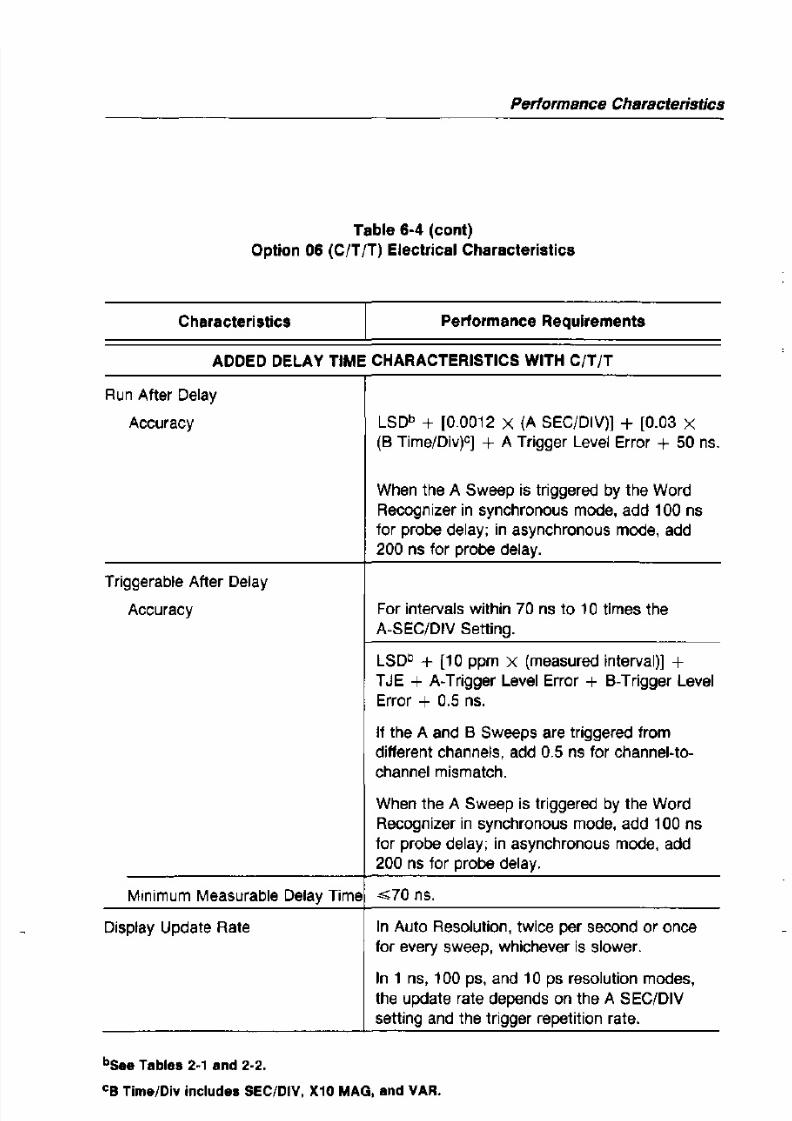
8/2/2019 2465A 2455A 2445A Operators Manual
http://slidepdf.com/reader/full/2465a-2455a-2445a-operators-manual 139/182
Characteristics Performance Requirements
ADDED DELAY TIME CHARACTERISTICS WITH CIT IT
Run After Delay
Accuracy
Triggerable After Delay
Accuracy
LSDb + [0.0012 X (A SEC/DIV)) + [0.03 X
(B Time/Div)C) + A Trigger Level Error + 50 ns.
When the A Sweep is triggered by the Word
Recognizer in synchronous mode, add 100 nsfor probe delay; in asynchronous mode, add
200 ns for probe delay.
For intervals within 70 ns to 10 times the
A·SEC/DIV Setting.
LSDb + [10 ppm X (measured interval)] +T JE + A-Trigger Level Error + B-Trigger Level
Performance Characteristics
Table 6-4 (cont)
Option 06 (C/T/T) Electrical Characteristics

8/2/2019 2465A 2455A 2445A Operators Manual
http://slidepdf.com/reader/full/2465a-2455a-2445a-operators-manual 140/182
Characteristics Performance Requirements
ADDED DELTA-DE LAY-TIME CHARACTERISTICS WITH C/T/T
Run After Delay
Accuracy
Triggerable After Delay
Accuracy
Superimposed Delta Time
LSDb + [0.0008 X (A SEC/DIV)] + [0.01 X(8 Time/Div)'] + 83 ps.
When the A Sweep is triggered by the Word
Recognizer in synchronous mode, add 1 ns for
probe jitter; in asynchronous mode, add 20 ns
for probe jitter.
Both delays are within 70 ns to 10 times the
A-SEC/DIV setling.
LSDb + [0.01 X (8 Time/Div)'] + [10 ppm X
(A SEC/DIV)] + [10 ppm X (measured interval)]
+ 50 ps + TJE.
If CH 3 or CH 4 is one channel of a two-channel
Performance Characteristics
Table 6-4 (cont)
Option 06 (CIT T) Electrical Characteristics

8/2/2019 2465A 2455A 2445A Operators Manual
http://slidepdf.com/reader/full/2465a-2455a-2445a-operators-manual 141/182
Characteristics Performance Requirements
DEFINITIONS
A Trigger Level Error = (A Trigger Level Readout Error)/SRA•
8 Trigger Level Error = (8 Trigger Level Readout Error)/SRB.
trREF = rise time, reference trigger signal.
trOELT = rise time, delta trigger signal.
SR A = slew rate at trigger point, A sweep trigger signal in diY/sec.
SRB = slew rate at trigger point, 8 sweep trigger signal in diy/sec.
SRREF = slew rate at trigger point, reference trigger signal in diY/sec.
SR DELT = slew rate at trigger point, delta trigger signal in diY/sec.
Performance Characteristics
Table 6·4 (cont)
Option 06 (C/T/T) Electrical Characteristics

8/2/2019 2465A 2455A 2445A Operators Manual
http://slidepdf.com/reader/full/2465a-2455a-2445a-operators-manual 142/182
Characteristics Performance Requirements
Delta Trigger Signal Jitter = (ens + enoELT)/SROELT'
= a or Frequency or Delay mode.
enOELT = delta signal rms noise in div.
A Trigger Signal Sweep Jitter = (ens + enA)/SRA.
enA = A sweep trigger signal rms noise in div.
When the Word Recognizer supplies a trigger in synchronous mode, the trigger
jitter of the associated trigger signal is <1 ns; in asynchronous mode, the
associated trigger signal jitter is <20 ns.
N = number of averages during measurement interval.
= see Table 2-1 for Delay or Delta Time.
Performance Characteristics
Table 6-5Option 09 (WR) Electrical Characteristics

8/2/2019 2465A 2455A 2445A Operators Manual
http://slidepdf.com/reader/full/2465a-2455a-2445a-operators-manual 143/182
Characteristics Performance Requirements
SYNCHRONOUS MODE
Data Setup Time
00-015 and Q
Data Hold Time
0 0-°15 and Q
Minimum Clock Pulse Width
High
Low
Minimum Clock Period
Delay from Selected Clock Edge
to Word Out from C/T/T
25 ns.
ons.
20 ns.
20 ns.
50 ns.
..-;;;55 ns.
Performance Characteristics
Table 6-5 (cont)Option 09 (WR) Electrical Characteristics

8/2/2019 2465A 2455A 2445A Operators Manual
http://slidepdf.com/reader/full/2465a-2455a-2445a-operators-manual 144/182
Characteristics Performance Requirements
INPUTS AND OUTPUTS
Input Voltages
Minimum Input Voltage A -0.5 v.
Maximum Input Voltage A 5.5 V.
Maximum Input Low Voltage 0.6 V.Minimum Input High Voltage 2.0 V.
WORD RECOG OUT
High > 2.5 V LSTTL output.
Low <0.5
V LSTTL output.Input High Current ~ 2 0 / . L A .
Performance Characteristics
Table 6·6Option 10 (GPIB) Electrical Characteristics

8/2/2019 2465A 2455A 2445A Operators Manual
http://slidepdf.com/reader/full/2465a-2455a-2445a-operators-manual 145/182
Characteristics Performance Requirements
Vertical Position Accuracy Position accuracy is only valid when:
1. Positioning occurs after a BALance
command is invoked at the ambient
temperature in which the
instrument is operating.
2. The VOL TS/DIV VAR control is in
the calibrated detent.
CH 1, CH 2 (noninverted)
+15'C to +35'C ± (0.3 div + 3% of distance from center
screen in div + 0.5 mV/VIDIV setting.)
CH 2 Inverted Add 0.2 div.
-15 'C to +15'C and +35'C Add 1.5 mV/VIDIV setting.
Performance Characteristics
Table 6-7Mechanical Characteristics

8/2/2019 2465A 2455A 2445A Operators Manual
http://slidepdf.com/reader/full/2465a-2455a-2445a-operators-manual 146/182
Characteristics Description
Weight
With Accessories and Pouch 10.2 kg (22.4 Ib).
With Option 05, 06 and 09, or 10 12.0 kg (26.44 Ib).
With Option 01 13.1 kg (28.8 Ib).
Without Accessories and Pouch 9.3 kg (20.5 Ib).
Domestic Shipping Weight
2465A, 2455A, 2445A 12.8 kg (28.2 Ib).
With Option 05, 06 and 09, or 10 17.6 kg (38.8 Ib).
With Option 01 19.2 kg (42.2 Ib).
Height
Without Accessories Pouch
Performance Characteristics
-: 9L±1 CC 2L 6Sf>, 2455A .

8/2/2019 2465A 2455A 2445A Operators Manual
http://slidepdf.com/reader/full/2465a-2455a-2445a-operators-manual 147/182
20?:t25.4C
T-----
9.56±1 CC
243±25.40-
1
_1
~ { ; " -t,--- -/
- - - - - - - - - ~
c:=b-1
'l,------
---- 15,60
---20. CC
:')08
2445A, VUH OR
I'IlTHO'JT OP7!Or--.;S
:]5, 06 ,A,ND 09.
A · ~ C ' 10
2 4 6 ~ A , 2455,';,24L.SA N. ---i
: J ~ T I O \ l (I'

8/2/2019 2465A 2455A 2445A Operators Manual
http://slidepdf.com/reader/full/2465a-2455a-2445a-operators-manual 148/182
Performance Characteristics
Table 6-8 (coni)
Environmental Requirements

8/2/2019 2465A 2455A 2445A Operators Manual
http://slidepdf.com/reader/full/2465a-2455a-2445a-operators-manual 149/182
Characteristics
Shock (operating and
nonoperating)
Not Rack Mounted
Rack Mounted
Transit Drop (not in
shipping package)
Bench Handling (cabinet on
and cabinet off)
Topple (operating with
cabinet installed)
Packaged Transportation
Drop
Performance Requirements
50 g. half sine, 11 ms duration, three shocks on each
face, for a total of 18 shocks.
30 g.
8-inch drop on each corner and each face
(MIL-T-28800C, para. 4.5.5.4.3).MIL-STD-810C, Method 516.2, Procedure V
(MIL-T-28800C, para. 4.5.5.4.3).
Set on rear feet and allow to topple over onto each of
four adjacent faces (Tektronix Standard 062-2858-00).
Meets the limits of the National Safe Transit Assn., test
procedure 1 A-B-2; 10 drops of 36 inches (Tektronix

8/2/2019 2465A 2455A 2445A Operators Manual
http://slidepdf.com/reader/full/2465a-2455a-2445a-operators-manual 150/182
SECTION

8/2/2019 2465A 2455A 2445A Operators Manual
http://slidepdf.com/reader/full/2465a-2455a-2445a-operators-manual 151/182
7Options
and
Accessories

8/2/2019 2465A 2455A 2445A Operators Manual
http://slidepdf.com/reader/full/2465a-2455a-2445a-operators-manual 152/182
Options and Accessories
Introduction
This section contains a general description of instrument options available atthe time of publication of this manual. Also included is a complete list (with
Tektronix part numbers) of standard accessories included with each instrument and

8/2/2019 2465A 2455A 2445A Operators Manual
http://slidepdf.com/reader/full/2465a-2455a-2445a-operators-manual 153/182
a partial list of optional accessories. Additional information about instrument
options, option availability, and other accessories can be obtained either by
consulting the current Tektronix Product Catalog or by contacting your local
Tektronix Field Office or representative.
Options 01, 05, 06 and 09, and 10 are discussed throughout this manual.
Option 11
Option 11 provides two probe-power connectors on the rear panel of the
instrument. Voltages supplied at these connectors meet the power requirements of
standard Tektronix active oscilloscope probes.
Option 1R
Options and Accessories
Power Cord Options
Instruments are shipped with the detachable power-cord configuration orderedby the customer. Descriptive information about the international power-cord
options is provided in Section 1, "Preparation for Use." The following list identifies

8/2/2019 2465A 2455A 2445A Operators Manual
http://slidepdf.com/reader/full/2465a-2455a-2445a-operators-manual 154/182
the Tektronix part numbers for the available power cords and associated fuses.
Option Al (Universal Euro)
Power cord (2.5 m) 161-0104-06Fuse (1.6 A, 250 V,
5 x 20 mm, Quick-acting) 159-0098-00
Option A2 (UK)
Power cord (2.5 m) 161-0104-07
Fuse (1.6 A, 250 V,5 x 20 mm, Quick-acting) 159-0098-00
Option A3 (Australian)
Power Cord (2.5 m) 161-0104-05
Fuse (1.6 A, 250V,
5 x 20 mm, Quick-acting) 159-0098-00
Options and Accessories
Standard Accessories
The following standard accessories are provided with each instrument:
Qty Description Part Number

8/2/2019 2465A 2455A 2445A Operators Manual
http://slidepdf.com/reader/full/2465a-2455a-2445a-operators-manual 155/182
2 Probes (10X, 1.3 m) with Accessories
(2465A and 2455A) P6136 Op1 01
2 Probes (10X, 2 m) with Accessories(2445A) P6133 Opt 01
Banana Plug/
Binding Post Adaptor 134-0016-01
Accessory Pouch, Snap Fastener 016-0692-00
Accessory Pouch, Zip-lock Fastener 016-0537-00
Operators Manual 070-6014-00
Fuse (2 A, 250 V) 159-0021 -00
CRT Filter, Blue Plastic (installed) 378-0199-00
CRT Filter, Clear Plastic 378-0208-00
Front Cover 200-3199-00

8/2/2019 2465A 2455A 2445A Operators Manual
http://slidepdf.com/reader/full/2465a-2455a-2445a-operators-manual 156/182
Optional Accessories
The following optional accessories are recommended:
Options and Accessories

8/2/2019 2465A 2455A 2445A Operators Manual
http://slidepdf.com/reader/full/2465a-2455a-2445a-operators-manual 157/182
Description
Protective Cover, Waterproof, Blue Vinyl
Probe Package:
2465A and 2455A
2445A
Rackmounting Conversion Kit
Polarized Collapsible Viewing Hood
Folding Viewing Hood, L i g h t ~ s h i e l d i n g
Collapsible Viewing Hood, Binocular
Oscilloscope Camera
SCOPE-MOBILE Cart
Carrying Strap
Part Number
016-0720-00
P6136 Opt 01
P6133 Opt 01
016-0825-01
016-0180-00
016-0592-00
01 6-0566-00
See C3DB Series
200C
346-0058-00

8/2/2019 2465A 2455A 2445A Operators Manual
http://slidepdf.com/reader/full/2465a-2455a-2445a-operators-manual 158/182
APPENDIX

8/2/2019 2465A 2455A 2445A Operators Manual
http://slidepdf.com/reader/full/2465a-2455a-2445a-operators-manual 159/182
A

8/2/2019 2465A 2455A 2445A Operators Manual
http://slidepdf.com/reader/full/2465a-2455a-2445a-operators-manual 160/182
Appendix A
Extended Functions with Diagnostic
Exercisers

8/2/2019 2465A 2455A 2445A Operators Manual
http://slidepdf.com/reader/full/2465a-2455a-2445a-operators-manual 161/182
Diagnostic exercisers provide access to an operating-time log and they control
instrument setup modes and the viewing-time display. The available GPIB interface
adds exercisers to establish system parameters of the instrument and to transfer the
set of thirty saved setups from one instrument to one or more other instruments. With
the available TelevisionNideo (TV) enhancement, added exercisers control video line
numbering. The available DMM also adds an exerciser, DM EXER 72. The Service
Manual describes other exercisers which are used only for instrument testing and
troubleshooting.
EXER 05
EXER 06EXER 07
EXER 08
GP EXER 11
GP EXER 12
GP EXER 13
GP EXER 14
Display Operating Time and Power Cycle Count
Select Setup to Use at Power UpEnable/Disable Setup SAVE and Sequence Definition
Initialize Setups
Program GPIB Address
Program GPIB Message Terminator and Talk/Listen
Receive-Setups Mode
Send-Setups Mode
Appendix A
In the descriptions below, the lines marked with ">" show what is displayed in the
top row of the readout.
EXER 05 Display Operating Time and Power Cycle Count

8/2/2019 2465A 2455A 2445A Operators Manual
http://slidepdf.com/reader/full/2465a-2455a-2445a-operators-manual 162/182
> HRS ON nnnn OFF/ON CYCLES mmmm
EXER 06
nnnn = Accumulated Number of Hours with Power Applied
mmmm = Accumulated Number of Power Cycles
Select Setup to Use at Power Up
> POWER UP TO POWER DOWN SETUP
Instrument will power up with the setup in effect at power down.
> POWER UP TO SETUP 1
Instrument will power up with the setup stored as setup 1.
EXER 07 Enable/Disable Setup SAVE and Sequence Definition
> ENABLE SAVE AND SEQUENCE-CHANGE
Appendix A
GP EXER 11 Program GPIB Address
> GPIB ADDRESS nn
nn = a primary address within a o 31. Turn the 6. control
to select the appropriate address. With address 31, bus data
has no effect on the instrument and is unaffected by the
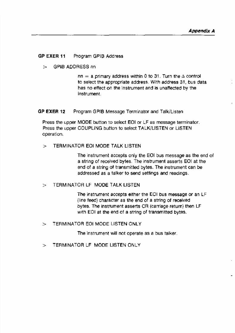
8/2/2019 2465A 2455A 2445A Operators Manual
http://slidepdf.com/reader/full/2465a-2455a-2445a-operators-manual 163/182
instrument.
GP EXER12 Program GPrB Message Terminator and Talk/Listen
Press the upper MODE button to select EOI or LF as message terminator.
Press the upper COUPLING button to select TALK/LISTEN or LISTEN
operation.
> TERMINATOR EOI MODE TALK LISTEN
The instrument accepts only the EOr bus message as the end of
a string of received bytes. The 'Instrument asserts EOI at the
end of a string of transmitted bytes. The instrument can be
addressed as a talker to send settings and readings.
> TERMINATOR LF MODE TALK LISTEN
The instrument accepts either the EOI bus message or an LF(line feed) character as the end of a string of received

8/2/2019 2465A 2455A 2445A Operators Manual
http://slidepdf.com/reader/full/2465a-2455a-2445a-operators-manual 164/182

8/2/2019 2465A 2455A 2445A Operators Manual
http://slidepdf.com/reader/full/2465a-2455a-2445a-operators-manual 165/182

8/2/2019 2465A 2455A 2445A Operators Manual
http://slidepdf.com/reader/full/2465a-2455a-2445a-operators-manual 166/182
APPENDIX

8/2/2019 2465A 2455A 2445A Operators Manual
http://slidepdf.com/reader/full/2465a-2455a-2445a-operators-manual 167/182
B

8/2/2019 2465A 2455A 2445A Operators Manual
http://slidepdf.com/reader/full/2465a-2455a-2445a-operators-manual 168/182
AppendixB
Sequence Programming and Operation
As many as thirty stored setups can be organized into one or more sequences
to be sequentially recalled by the STEP/AUTO button. Unless otherwise defined, all
thirty setups can be recalled in one sequence.

8/2/2019 2465A 2455A 2445A Operators Manual
http://slidepdf.com/reader/full/2465a-2455a-2445a-operators-manual 169/182
A sequence is defined as a contiguous group of saved setups, where the first
setup includes the BEGIN attribute and the last setup includes the END attribute.
The Sequence-Save mode provides accessto
the BEGIN/END attributes andprovides sequence editing facilities to REPLACE, INSERT, and DELETE setups.
Pressing SAVE establishes the Direct-Save mode, as described in the
"Operation" section. Pressing STEP then establishes the Sequence-Save mode.
The readout shows a definition mode, a step attribute. a setup number. the
"NAME:H prompt. and the name argument in the top row and a HELP message inthe bottom row. (If the Direct-Save mode displays "SAVE FUNCTIONS
DISABLED" or if the Sequence-Save mode displays "SEQUENCE DEFINITION
DISABLED," refer to EXER 07, described in Appendix C.)
Top Row
or
or
REPLACE STEP :nn
REPLACE BEGIN :nn
REPLACE END :nn
NAME:xxxxxxx
NAME:xxxxxxx
NAME:xxxxxxx
AppendixB
While REPLACE is selected, repeated operation of SAVE presents this cycle of
HELP messages in the bottom row.
Top Rowor
or
REPLACE STEP :nn NAME:xxxxxxxREPLACE BEGIN :nn NAME:xxxxxxx
REPLACE END :nn NAME:xxxxxxx

8/2/2019 2465A 2455A 2445A Operators Manual
http://slidepdf.com/reader/full/2465a-2455a-2445a-operators-manual 170/182
Bottom Row
or
or
or
PUSH STEP TO REPLACE SETUP.
TURN c, REF TO FIELD, THEN-
TURN t> TO DESIRED SETIING.
PUSH RECALL TO CANCEL THIS MODE.
When STEP is pressed in the INSERT definition mode, the numbers attached to
the currently selected setup and each higher-numbered setup are increased by one
and setup 30 is discarded. The current instrument setup, the displayed step
attribute, and the displayed NAME are then stored in the selected memory location.
While INSERT is selected. repeated operation of SAVE presents this cycle of
HELP messages in the bottom row.
Top Row
or
or
INSERT STEP :nn NAME:xxxxxxx
INSERT BEGIN ;nn NAME:xxxxxxx
INSERT END :nn NAME:xxxxxxx
Appendix B
ExecuffngSequences
Pressing RECALL establishes the Direct-Recall mode, as described in the
Operation section. Then pressing STEP in the Direct-Recall mode enables the
Sequence-Recall mode. The top row of the readout shows the names of the first
four defined BEGIN steps. If no BEGIN steps are defined, step 1 is the beginning
of a sequence, by default. Pressing a setup-number button initiates the

8/2/2019 2465A 2455A 2445A Operators Manual
http://slidepdf.com/reader/full/2465a-2455a-2445a-operators-manual 171/182
corresponding sequence and illuminates the STEP indicator. The position of each
button among the others corresponds to the position of a sequence name among
the others on the screen. Pressing STEP initiates the first defined sequence and
illuminates the STEP indicator.
Repeatedly pressing RECALL presents this cycle of HELP messages. In
message 1, "_n° is blank, "-2," "-3," or "-4," depending on how many
sequences are defined.
Bottom Row -
or
or
PUSH 1-n OR STEP TO START SEQ.
TURN" TO SELECT ANY STEP.
PUSH SAVE TO CANCEL THIS MODE.
Turning ,1 REF or ..l while in the Sequence-Recall mode accesses to any setup.

8/2/2019 2465A 2455A 2445A Operators Manual
http://slidepdf.com/reader/full/2465a-2455a-2445a-operators-manual 172/182
APPENDIX
c

8/2/2019 2465A 2455A 2445A Operators Manual
http://slidepdf.com/reader/full/2465a-2455a-2445a-operators-manual 173/182

8/2/2019 2465A 2455A 2445A Operators Manual
http://slidepdf.com/reader/full/2465a-2455a-2445a-operators-manual 174/182
AppendixC
Power Up Tests
Power-up tests are automatically performed each time the instrument is turned on.
These tests provide the user with the highest possible confidence that the instrument
is operational. They include a Kernel test and Confidence tests.

8/2/2019 2465A 2455A 2445A Operators Manual
http://slidepdf.com/reader/full/2465a-2455a-2445a-operators-manual 175/182
Kernel Test
A kernel test failure is considered ~ f a t a l " to the operation 01 the instrument. A
Kernel test failure causes the TRIG'D indicator to flash and displays a binary code
pattern on other front panel indicators. If a kernel test fails, the user can attempt to
operate the instrument normally by pressing the NB TRIG button. Operation is
unpredictable; it depends on the natureof
the failure.
Confidence Tests
Confidence tests are performed after the processor kernel has been found
operational. These tests check a portion of the instrument for correct operation.
Appendix C
Table C-l
Confidence Test Numbers and Affected Functions
Test Number Description
01 Controlier Timing Signal Missing or Wrong Period

8/2/2019 2465A 2455A 2445A Operators Manual
http://slidepdf.com/reader/full/2465a-2455a-2445a-operators-manual 176/182
02 Momentary Switch Stuck
03 Readout Interface or Memory Failure
04 Calibration Data Parity or Checksum Error
05 Main Board Failure Detected by Auto Level Trigger on LINE
Source
06 Memory·Battery Voltage Too High or Too Low
GP 11 GPIB Interface Failure Detected
DM 76 Digital Multimeter Failure Detected
APPENDIX

8/2/2019 2465A 2455A 2445A Operators Manual
http://slidepdf.com/reader/full/2465a-2455a-2445a-operators-manual 177/182
D

8/2/2019 2465A 2455A 2445A Operators Manual
http://slidepdf.com/reader/full/2465a-2455a-2445a-operators-manual 178/182
De/ta-Time and De/ta-De/ay-TimeAccuracy under Noted Conditions
for the C/T/T Option
Appendix D
1 0 " S ~ - - - - - r - - - - - ' - - - - - - - r - - - - - ' - - - - - - - - - - - - 7 ; - - - - - - '

8/2/2019 2465A 2455A 2445A Operators Manual
http://slidepdf.com/reader/full/2465a-2455a-2445a-operators-manual 179/182
>-0
"::J
00
"...
IIa:w....~ w,.
;::
' " S ~ - - - - ~ - - - - - - r - - - - - r - - - - - ~ - - - ~
100 ns
10 ns·
10 nsI
1 n s ~
1 ns1\
100 ps*
1\100 pS
Appendix D
De/ay-Time Accuracy under Noted Conditionsfor the C/T/T Option
100 s
s

8/2/2019 2465A 2455A 2445A Operators Manual
http://slidepdf.com/reader/full/2465a-2455a-2445a-operators-manual 180/182
> 1 J.!s /:'Q":- -:::>U
;i, 100 n>
s10 ns·
I'
, --0'd:
W
>-
:;
10 ps*- l ns·
10 ns·::IE 10 ni=
s - ' ~ ( > 1 ns *
1 ns100 ps· ::;...--
10 PS"I
DMM
DCV ACV dBV CONT Hlfl
00000DCA ,\CA ,Bm Lon
Tektronix 2465A(),;( (I;'! GPtB S-:-':"ILS
01 '·0'" -' O ~ t ' "
M I ~ IoIAX REF
SHIFT ~ { l L O DISPLAY DISPLAY
o o DO DSMOOTH MIN M A ~ REF
RESET SET
SETUP VERTICALSTEP! {; POSITION {: POSITION ~ P O S I T I O N L ) "0AUTO '70 MAG
0 ~ \ _ - j , , 0- j
MODE
SAVE C" , C" 2 eH 3 C" , 'RACK!
HELP ,2 3
, 1 ! ~ t INOEP
0 0 0 0 0 0 0 0
TRIGGER
HOLDOFF
( -
AlB MENU SLOPE INIT:):50,
0 0 0

8/2/2019 2465A 2455A 2445A Operators Manual
http://slidepdf.com/reader/full/2465a-2455a-2445a-operators-manual 181/182
"II I I III f
· - - ~ - - r - - + - - ~ ~ ~ - + - - + - ~ - - ~ ~ I I~ " . ~ : : L
INTENSITY FOCUS READOUT INTENSITY SCALE IllUM POWEA
e l ~ ~ ' RACE II ""'
0I I ~ l
0l o - ~ ' I U ~ (, ~ S ' G
0 ©0 @ C2)\ @\ - - . / ~ s r A I ; '-. -' > ~ A _ l :"f
fArlell, , ~ C - : R S :11,HI Wi )
RECAll ADD INVERT CHoe! 1 jMHI ~ R E F u R D L Y P O S .,:,.HELP
'"BWlIMIT
0 0 0 D 0
VOLTS/DIV VOLTS/DIV
0 ~ D V 2mV
PUSH B J T ~ - 8 A I A ~ C [ TV ClAM,
l ~ n ,c
i j ~ U 50Q [)c
C)
oCH 1",E.l
lM1115pF::::400Vpk
5011 :;5V RMS
'Mn
~ , u n
"0G ~ D
OC
0NJ
CC
CH 2lMn 15pF::::400Vpk
(50115.'JVRMS
o 'Wy'"MENU SE:ECT
P U l l - l ~ I 'URN-AL' P U , ~ B
8SIIiF
PUII-ADJCH2UlY
TRACE
(5.j POSITION
CH 3l M n 1 5 ~ F : : : : 4 0 0 V p k
> l R I ~ l
AU I lVl I'[KI OC
AAU'e, CHI ~ O I S , NOKM el , ", "USGl SlU CH 3 ",<FNU-
'" "BR U ~ Afl LlNl LINES
TRIG Ol1 FLO' ~ l ' T\
TRIG ->OLY FLO, f,J
MODE SOURCE COUPLING
C)C)
00VOLTS/D!V
.5V/.lV 5V/.IV
o 0
CALIBRATORJ15H7·5MHI
COI<P PROBE 2 :ml
1:118 (§ I J T \ ~ lMrl our)
[_ POSITION
0 ~ . : 0 ,\".
CH 4IMn 1 5 ~ F : : : : 4 0 0 V p k
6014·11
r CAUTION
HI AI/Oj[) HEeTlllC SHOCK THE POWER CORD
PROTECTIVE 6RDUN-DlNG CONDUCTOR 'AUST Bf

8/2/2019 2465A 2455A 2445A Operators Manual
http://slidepdf.com/reader/full/2465a-2455a-2445a-operators-manual 182/182
CONNECTED TO Gl!OltNI).
UU NOT R < M O V ~ COVlRS RHER SERVICING fllOUAUFIHl PEIISONNEL
DISCONNECT INPUT POWER BEfORE REPLACING fl)S[
FOR CDN-TlN-UW fiRE PROH.CTION R£P\AU ONLY
WITH SPfClflW TYPE AND RATED fUSE.
POWER MAX WATTS 1;>0
MAl( VA lBO
,REO 48441m,
'fIlfHQNIX GU[flNSfY t i l l L I
GPIS C O N N E C T Q ~ ItEr sm 4S8 r-QAI
SHI, IIK1. In 13. SRI All,fP\l OCI, oU, C ~ , H
,_...... . . . . . . . . . . ,
CH 2 SIGNAL OUT A GAn aliT STEP/AUTO il GAn OUT
IO",VIOIV INTO 50 n TH It EXT SWITCH TTL n
.....
E ~ T Z AXIS - ; - N ~ ,:::::S'lpl;l TTL It BLANKS)
f )
6014-12