242-515 agd: 10. meshes11 objective o to describe how shape meshes and models can be used, with...
TRANSCRIPT

242-515 AGD: 10. Meshes 11
• Objectiveo to describe how shape meshes and models
can be used, with emphasis on the OBJ and MTL 3D formats
Animation and Games
Development242-515, Semester 1, 2014-2015
10. Meshes and Models
242-515 AGD: 10. Meshes 22
1. Triangle Meshes2. Three Custom Meshes3. Phong and Gouraud Shading4. jME Built-in Shapes5. Using Models6. Loading Models into a Grid7. Using the Chase Camera8. The Wavefront (.obj) Format9. OBJ Cube Example10.Other Geometric Models
Overview
242-515 AGD: 10. Meshes 33
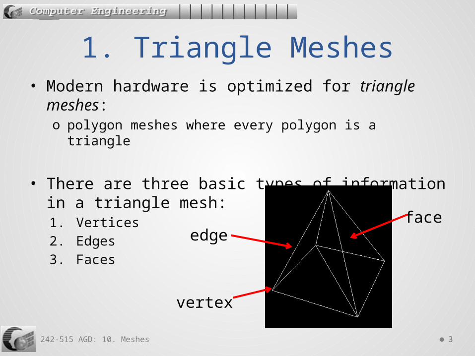
• Modern hardware is optimized for triangle meshes: o polygon meshes where every polygon is a triangle
• There are three basic types of information in a triangle mesh:1. Vertices2. Edges3. Faces
1. Triangle Meshes
vertex
edgeface

242-515 AGD: 10. Meshes 44
1. Vertices. Each triangle has exactly three vertices. A vertex may be shared by many triangles.
2. Edges. An edge connects two vertices. Each triangle has three edges. Usually, each edge is shared by two faces.
3. Faces. The surfaces of the triangles. Usually stored as a list of three vertices, or a list of three edges.
Triangle Mesh Information

242-515 AGD: 10. Meshes 55
+X
+Z
+Y
(1,0,1)
(1,0,-1)
(-1,0,1)
(-1,0,-1)
(0,2,0)
A Pyramid

242-515 AGD: 10. Meshes 66
• An indexed triangle mesh consists of a list of vertices, and a list of triangles indicies.
Indexed Triangle Mesh
+X
+Z
+Y
(1,0,1)
(1,0,-1)
(-1,0,1)
(-1,0,-1)
(0,2,0)
0 1
2
3
4

242-515 AGD: 10. Meshes 77
• Each triangle is represented using three indices. • The index order is specified in terms of the front
face of the triangle. • The index order follows the right-hand rule:
o the front faces the direction of the thumbo the vertices indicies are listed in the counterclockwise
order of the fingers
Index Order and Front Faces
242-515 AGD: 10. Meshes 88
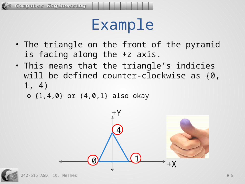
• The triangle on the front of the pyramid is facing along the +z axis.
• This means that the triangle's indicies will be defined counter-clockwise as {0, 1, 4)o {1,4,0} or (4,0,1} also okay
Example
+X
+Y
0 1
4
242-515 AGD: 10. Meshes 99
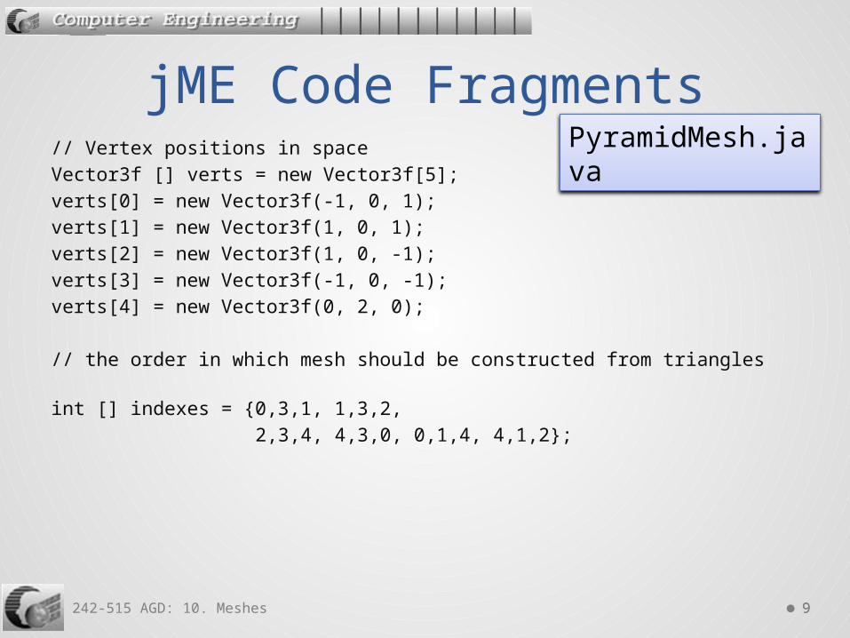
jME Code Fragments// Vertex positions in space Vector3f [] verts = new Vector3f[5]; verts[0] = new Vector3f(-1, 0, 1); verts[1] = new Vector3f(1, 0, 1); verts[2] = new Vector3f(1, 0, -1); verts[3] = new Vector3f(-1, 0, -1); verts[4] = new Vector3f(0, 2, 0);
// the order in which mesh should be constructed from triangles int [] indexes = {0,3,1, 1,3,2, 2,3,4, 4,3,0, 0,1,4, 4,1,2};
PyramidMesh.java

242-515 AGD: 10. Meshes 1010
// mesh creationMesh mesh = new Mesh();
// Setting mesh buffers // the 2nd parameter is the number of components in each value mesh.setBuffer(Type.Position, 3, BufferUtils.createFloatBuffer(verts)); mesh.setBuffer(Type.Index, 1, BufferUtils.createIntBuffer(indexes)); mesh.updateBound();

242-515 AGD: 10. Meshes 1111
// mesh is displayed as a white wireframe Geometry geom = new Geometry("pyramid", mesh); Material matWF = new Material(assetManager, "Common/MatDefs/Misc/Unshaded.j3md"); matWF.setColor("Color", ColorRGBA.White); geom.setMaterial(matWF); rootNode.attachChild(geom);
RenderState rs = matWF.getAdditionalRenderState(); rs.setWireframe(true); // activate wireframe view rs.setFaceCullMode(RenderState.FaceCullMode.Off);
cam.setLocation(new Vector3f(0.5f, 3.5f, 4)); cam.lookAt(Vector3f.ZERO, Vector3f.UNIT_Y); // look at the origin with +y-axis being up

242-515 AGD: 10. Meshes 1212
Execution

242-515 AGD: 10. Meshes 1313
2. Three Custom Meshes
solid blue
coloredverticies
lit with adirectionallight
CustomMeshes.java

242-515 AGD: 10. Meshes 1414
The Basic Mesh
+X
+Y
0 1
2 3
(0,0,0) (2,0,0)
(0,2,0) (2,2,0)

242-515 AGD: 10. Meshes 1515
Mesh mesh = new Mesh();
// Vertex positions in space Vector3f[] verts = new Vector3f[4]; verts[0] = new Vector3f(0,0,0); // can use any ordering verts[1] = new Vector3f(2,0,0); verts[2] = new Vector3f(0,2,0); verts[3] = new Vector3f(2,2,0);
// the order in which mesh should be constructed from triangles int[] indexes = {2,0,1, 1,3,2};
// setting the buffersmesh.setBuffer(Type.Position, 3, BufferUtils.createFloatBuffer(verts)); mesh.setBuffer(Type.Index, 1, BufferUtils.createIntBuffer(indexes)); mesh.updateBound();
Create the Mesh

242-515 AGD: 10. Meshes 1616
Geometry geom = new Geometry("solid", mesh); Material mat = new Material(assetManager, "Common/MatDefs/Misc/Unshaded.j3md"); mat.setColor("Color", ColorRGBA.Blue); geom.setMaterial(mat); geom.setLocalTranslation(-2, -3, 0); rootNode.attachChild(geom);
A Solid Blue Mesh

242-515 AGD: 10. Meshes 1717
Mesh colMesh = mesh.clone();
Geometry colGeom = new Geometry ("colored", colMesh); Material colMat = new Material(assetManager, "Common/MatDefs/Misc/Unshaded.j3md"); colMat.setBoolean("VertexColor", true);
// each vertex requires 4 color values (R G B A) // in the same ordering as the vertices array, verts[] float[] colorArray = {
1f, 0f, 0f, 1f, // red
0.8f, 0.2f, 1f, 1f, // purple
0.8f, 0.2f, 1f, 1f, 0f, 0f, 1f, 1f }; // blue
// Set the color buffer colMesh.setBuffer(Type.Color, 4, colorArray); colGeom.setMaterial(colMat);
:
Coloured Verticies
0 1
2 3
242-515 AGD: 10. Meshes 1818
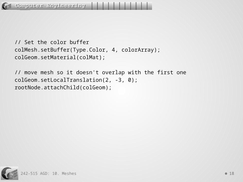
// Set the color buffer colMesh.setBuffer(Type.Color, 4, colorArray); colGeom.setMaterial(colMat);
// move mesh so it doesn't overlap with the first one colGeom.setLocalTranslation(2, -3, 0); rootNode.attachChild(colGeom);

242-515 AGD: 10. Meshes 1919
Mesh litMesh = mesh.clone(); Geometry litGeom = new Geometry ("lit", litMesh);
Material litMat = new Material(assetManager, "Common/MatDefs/Light/Lighting.j3md"); litMat.setBoolean("UseMaterialColors", true); litMat.setColor("Diffuse", ColorRGBA.Orange); // reflection litMat.setColor("Specular", ColorRGBA.White); litMat.setFloat("Shininess", 12); litGeom.setMaterial(litMat);
:
Lit Mesh, Reflecting Orange

242-515 AGD: 10. Meshes 2020
// verticies require normals for Phong lighting float[] normals = {0,0,1, 0,0,1, 0,0,1, 0,0,1}; // all of them point along +z axis litMesh.setBuffer(Type.Normal, 3, BufferUtils.createFloatBuffer(normals)); litGeom.setLocalTranslation(-2, 1, 0); rootNode.attachChild(litGeom);
// add a white light to make the lit object visible DirectionalLight dl = new DirectionalLight(); dl.setDirection(new Vector3f(1, 0, -2).normalizeLocal()); dl.setColor(ColorRGBA.White);
rootNode.addLight(dl);

242-515 AGD: 10. Meshes 2121
Vertex Normals Diagram
+X
+Z
+Y
0 1
2 3
(0,0,0)
(0,2,0)
(2,0,0)
(2,2,0)
directionallight

242-515 AGD: 10. Meshes 2222
• Phong shading interpolates normals between all the shape verticies. It uses these normals to calculate the shading for every pixelo many normals are generatedo this is the default shading technique in jME
• Gouraud shading calculates the shading for each vertex, and interpolates those shading values across every pixelo this requires less computation since only vertex normals
are needed
3.3. Phong and Gouraud Shading

242-515 AGD: 10. Meshes 2323
• The black arrows are the vertex normals.• The blue arrows are the interpolated surface
normals.• These extra normals will make the hexagon look
smoother on screen.
Phong Shading in Action

242-515 AGD: 10. Meshes 2424
• Phong shading makes polygons look smoother

242-515 AGD: 10. Meshes 2525
4. jME Built-in Shapes
Dome (the cone and pyramid are special cases)
Torus PQTorus Surface(a NURB)

242-515 AGD: 10. Meshes 2626
// Sphere mesh = new Sphere(16, 16, 1.0f); // Cylinder mesh = new Cylinder(20, 50, 1, 2, true); :
Geometry geom = new Geometry("Shape", mesh); Material mat = new Material(assetManager, "Common/MatDefs/Misc/Unshaded.j3md"); mat.setColor("Color", ColorRGBA.Blue); geom.setMaterial(mat);rootNode.attachChild(geom);
RenderState rs = mat.getAdditionalRenderState(); rs.setWireframe(true); // activate wireframe view rs.setFaceCullMode(RenderState.FaceCullMode.Off);
Viewing Wireframe ShapesWireShape.java

242-515 AGD: 10. Meshes 2727
Dome, Cone, Pyramid
Dome mesh = new Dome(Vector3f.ZERO, 32, 32, 1f, false); // center, planes, radialSamples, radius, insideView

242-515 AGD: 10. Meshes 2828
Dome mesh = new Dome(Vector3f.ZERO, 2, 32, 1f, false); // cone: planes == 2 and radialSamples > 4
242-515 AGD: 10. Meshes 2929
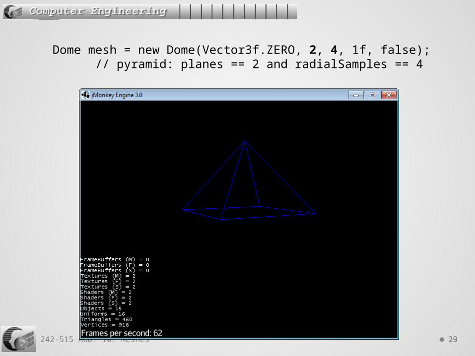
Dome mesh = new Dome(Vector3f.ZERO, 2, 4, 1f, false); // pyramid: planes == 2 and radialSamples == 4

242-515 AGD: 10. Meshes 3030
• For more information see http://en.wikipedia.org/wiki/Torus_knot
Knotted Doughnuts (braids)
PQTorus mesh = new PQTorus(2, -3, 2, 1, 64, 64); // trefoil// (2,−3) torus knot

242-515 AGD: 10. Meshes 3131
PQTorus mesh = new PQTorus(3, -8, 2, 0.5f, 64, 64); // Flower torus, (3, -8) torus knot
242-515 AGD: 10. Meshes 3232
• jME's built-in shapes come with pre-calculated normals, which can be displayed visually with the ShowNormals.j3md material definition.o a color gradient is calculated from the model's surface
normals. o no need for lights in the scene
Shapes and Normals

242-515 AGD: 10. Meshes 3333
public void simpleInitApp() { Cylinder mesh = new Cylinder(20, 50, 1, 2, true); Geometry geom = new Geometry("Shape", mesh); Material mat = new Material(assetManager,
"Common/MatDefs/Misc/ShowNormals.j3md"); geom.setMaterial(mat); geom.rotate(FastMath.HALF_PI, 0, 0); rootNode.attachChild(geom);}
Viewing a Cylinder's Normals
242-515 AGD: 10. Meshes 3434
• There are many free 3D models available onlineo e.g. at http://archive3d.net/,
http://sketchup.google.com/3dwarehouse/o see the list of websites at
http://www.hongkiat.com/blog/ 60-excellent-free-3d-model-websites/
• There are many 3D model formats:o e.g. 3D Studio (.3ds), Blender (.blend), Wavefront (.obj)o see the list at
http://edutechwiki.unige.ch/en/3D_file_format
5. Using Models

242-515 AGD: 10. Meshes 3535
• Blender (http://www.blender.org/)o extremely powerful, free, open source 3D modellero a confusing GUI which keeps being changedo use it to import models, and export them in a different
format
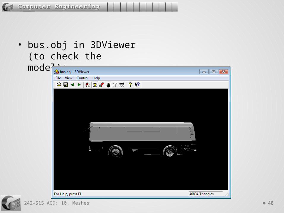
• 3DViewer (http://www.xs4all.nl/~karelse/3DViewer/)o very simple, free 3D viewer which is useful for checking
models
3D Tools

242-515 AGD: 10. Meshes 3636
• jME can load models in two formats:o Wavefront .obj formato Ogre XML
• I'll use .obj since it's a simple format, and is supported by most (all) 3D modeling tools.o the format is text-based, and is easy to edit manually
(see later)
• Blender can export Ogre XML files, but it requires the installation of a plugino details at http://jmonkeyengine.org/wiki/doku.php/
jme3:advanced:3d_models
3D Formats in jME

242-515 AGD: 10. Meshes 3737
• jME can also save Spatial nodes as .j3o binary files, which can be loaded later.o details at http://jmonkeyengine.org/wiki/doku.php/
jme3:advanced:save_and_load
• .j3o files can be viewed and edited by the jME SDK

242-515 AGD: 10. Meshes 3838
6. Loading Models into a Grid
GridZoneLoad.java

242-515 AGD: 10. Meshes 3939
The Grid Zone
+X
+Z
+Y
1 unit
1 unit
1 unit
0.1 unit
242-515 AGD: 10. Meshes 4040
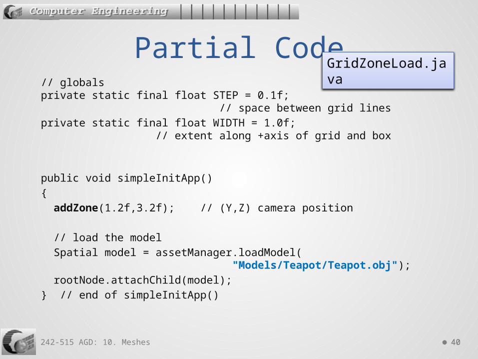
// globals private static final float STEP = 0.1f; // space between grid lines private static final float WIDTH = 1.0f; // extent along +axis of grid and box
public void simpleInitApp() { addZone(1.2f,3.2f); // (Y,Z) camera position
// load the model Spatial model = assetManager.loadModel( "Models/Teapot/Teapot.obj"); rootNode.attachChild(model); } // end of simpleInitApp()
Partial CodeGridZoneLoad.java
242-515 AGD: 10. Meshes 4141
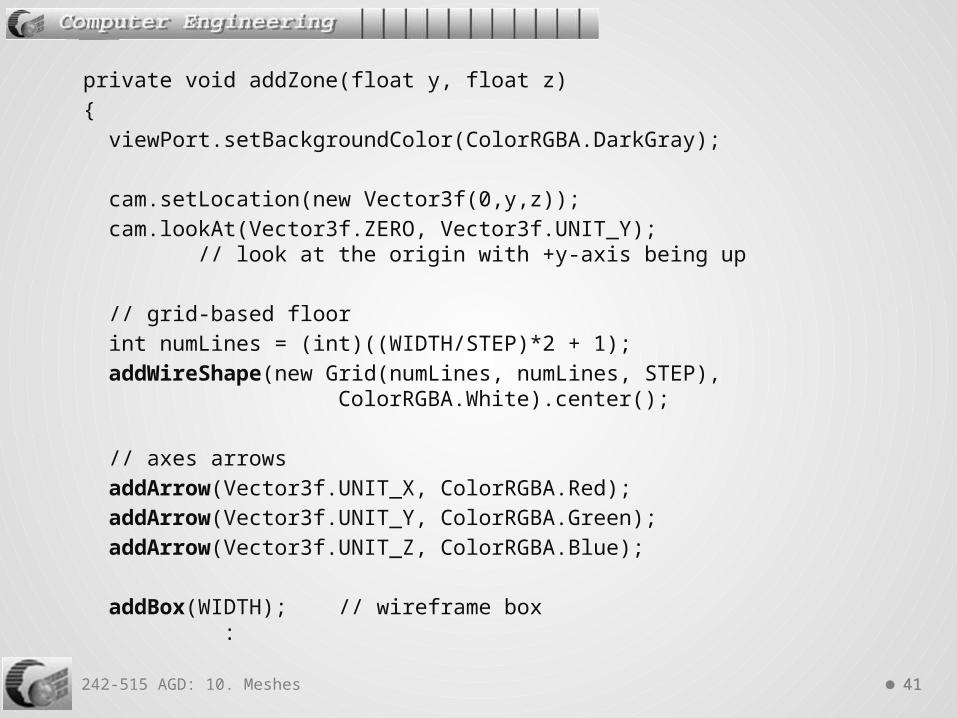
private void addZone(float y, float z) { viewPort.setBackgroundColor(ColorRGBA.DarkGray);
cam.setLocation(new Vector3f(0,y,z)); cam.lookAt(Vector3f.ZERO, Vector3f.UNIT_Y); // look at the origin with +y-axis being up
// grid-based floor int numLines = (int)((WIDTH/STEP)*2 + 1); addWireShape(new Grid(numLines, numLines, STEP), ColorRGBA.White).center();
// axes arrows addArrow(Vector3f.UNIT_X, ColorRGBA.Red); addArrow(Vector3f.UNIT_Y, ColorRGBA.Green); addArrow(Vector3f.UNIT_Z, ColorRGBA.Blue);
addBox(WIDTH); // wireframe box :

242-515 AGD: 10. Meshes 4242
// white light aimed down in front-left quadrant DirectionalLight dl1 = new DirectionalLight(); dl1.setDirection(new Vector3f(-1, -1, 1).normalizeLocal()); dl1.setColor( ColorRGBA.White); rootNode.addLight(dl1);
// white light aimed down in back-right quadrant DirectionalLight dl2 = new DirectionalLight(); dl2.setDirection(new Vector3f(1, -1, -1).normalizeLocal()); dl2.setColor( ColorRGBA.White); rootNode.addLight(dl2);
} // end of addZone()
xz
y
xz
y
242-515 AGD: 10. Meshes 4343
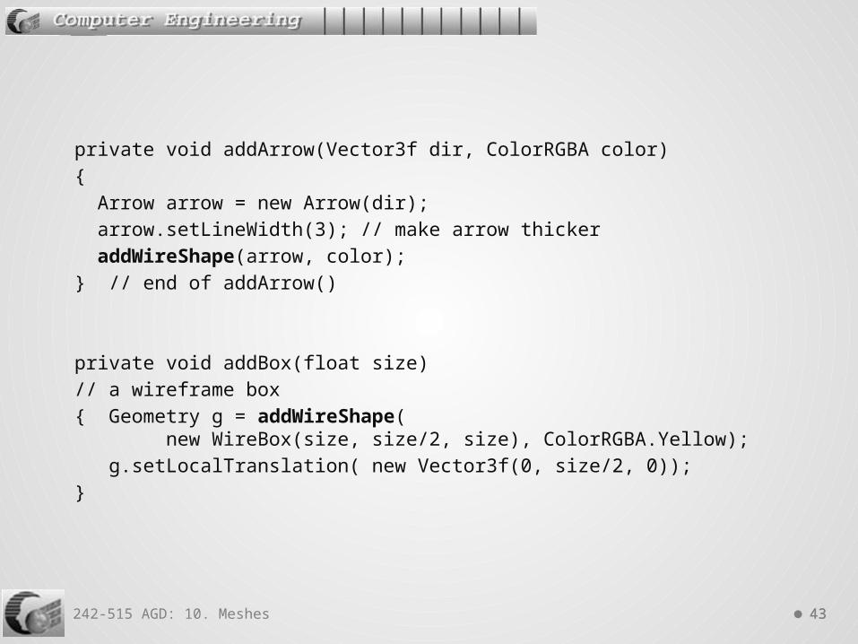
private void addArrow(Vector3f dir, ColorRGBA color) { Arrow arrow = new Arrow(dir); arrow.setLineWidth(3); // make arrow thicker addWireShape(arrow, color); } // end of addArrow()
private void addBox(float size) // a wireframe box { Geometry g = addWireShape( new WireBox(size, size/2, size), ColorRGBA.Yellow); g.setLocalTranslation( new Vector3f(0, size/2, 0)); }

242-515 AGD: 10. Meshes 4444
private Geometry addWireShape(Mesh shape, ColorRGBA color) // add a colored wireframe version of shape to the scene { Geometry g = new Geometry("shape", shape); Material mat = new Material(assetManager, "Common/MatDefs/Misc/Unshaded.j3md"); mat.getAdditionalRenderState().setWireframe(true); mat.setColor("Color", color); g.setMaterial(mat); rootNode.attachChild(g); return g; } // end of addWireShape()
242-515 AGD: 10. Meshes 4545
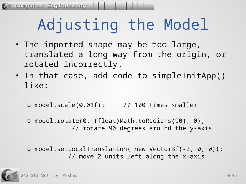
• The imported shape may be too large, translated a long way from the origin, or rotated incorrectly.
• In that case, add code to simpleInitApp() like:
o model.scale(0.01f); // 100 times smaller
o model.rotate(0, (float)Math.toRadians(90), 0); // rotate 90 degrees around the y-axis
o model.setLocalTranslation( new Vector3f(-2, 0, 0)); // move 2 units left along the x-axis
Adjusting the Model

242-515 AGD: 10. Meshes 4646
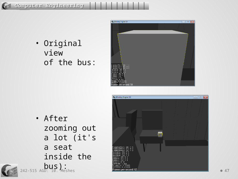
• The loaded bus.obj model is too large:o Spatial model = assetManager.loadModel( "models/bus.obj");
o bus.obj is in the local models/ directory
• I worked out the size problem by using the camera keys and mouse to move about:o the WASDQZ keys to zoom in/out
and translate left/right/up/down.o the mouse to rotate left/right/up/down
Bus Example
242-515 AGD: 10. Meshes 4747
• Original viewof the bus:
• After zooming out a lot (it's a seat inside thebus):
242-515 AGD: 10. Meshes 4848
• bus.obj in 3DViewer (to check the model):
242-515 AGD: 10. Meshes 4949
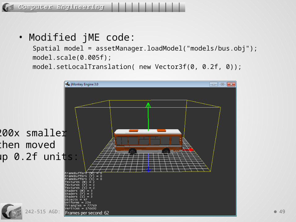
• Modified jME code:Spatial model = assetManager.loadModel("models/bus.obj");model.scale(0.005f); model.setLocalTranslation( new Vector3f(0, 0.2f, 0));
200x smallerthen movedup 0.2f units:

242-515 AGD: 10. Meshes 5050
Spatial model = assetManager.loadModel( "Models/HoverTank/Tank2.mesh.xml");model.scale(0.1f);model.rotate(0, -(float)Math.toRadians(90), 0);
HoverTank
10x smallerthen rotated-90 degreesaround they-axis:

242-515 AGD: 10. Meshes 5151
• A drawback of the default camera (a FlyByCamera object) is that rotation is around the camera's position.
• For model viewing, it is often better to rotate around the model.
• This is possible by using a ChaseCamera object insteado this kind of camera can rotate around a specified Spatialo it will also automatically follow the Spatal if it moves (i.e.
it chases the model)
7. Using the Chase Camera
242-515 AGD: 10. Meshes 5252
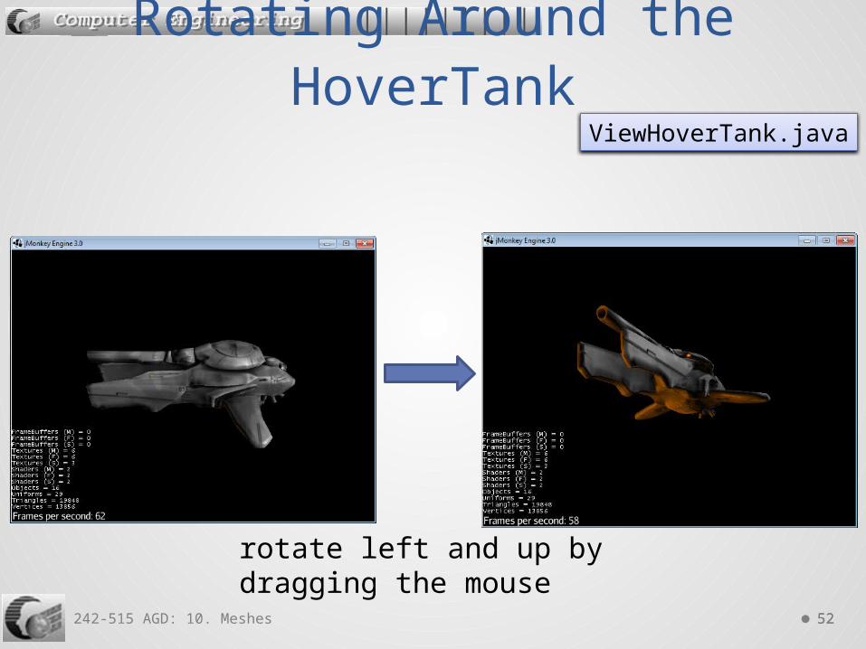
Rotating Around the HoverTank
ViewHoverTank.java
rotate left and up by dragging the mouse

242-515 AGD: 10. Meshes 5353
public void simpleInitApp() { Node tank = (Node) assetManager.loadModel( "Models/HoverTank/Tank2.mesh.xml"); rootNode.attachChild(tank);
// replace FlyByCamera by ChaseCamera flyCam.setEnabled(false); ChaseCamera chaseCam = new ChaseCamera(cam, tank, inputManager); // camera follows the tank and // can turn around it by dragging the mouse chaseCam.setSmoothMotion(true); chaseCam.setMaxDistance(100000); chaseCam.setMinVerticalRotation(-FastMath.PI / 2); :
Partial Code
242-515 AGD: 10. Meshes 5454
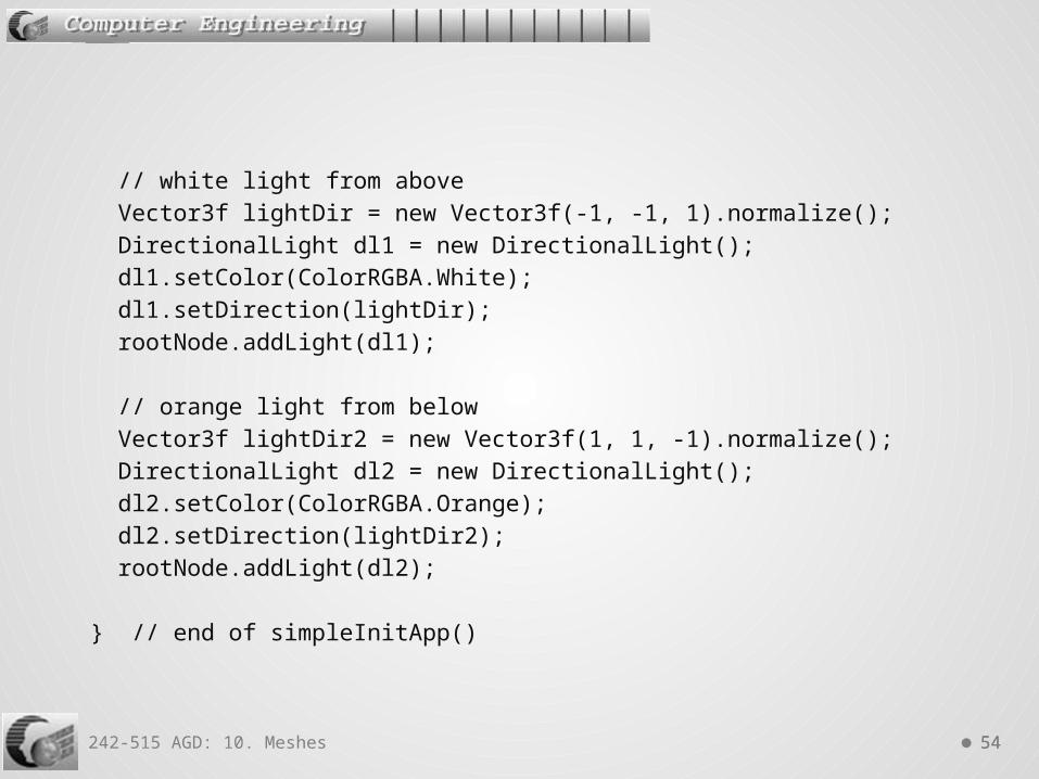
// white light from above Vector3f lightDir = new Vector3f(-1, -1, 1).normalize(); DirectionalLight dl1 = new DirectionalLight(); dl1.setColor(ColorRGBA.White); dl1.setDirection(lightDir); rootNode.addLight(dl1);
// orange light from below Vector3f lightDir2 = new Vector3f(1, 1, -1).normalize(); DirectionalLight dl2 = new DirectionalLight(); dl2.setColor(ColorRGBA.Orange); dl2.setDirection(lightDir2); rootNode.addLight(dl2);
} // end of simpleInitApp()

242-515 AGD: 10. Meshes 5555
• Most models are made up of triangles. • Each triangle is called a face.
• Each face is defined using verticeso a face may also have normals and texture coordinates
• Faces can be grouped together, and different groups can be assigned materials made from ambient, diffuse, and specular colors, and textures.
• • The material information is stored in a separate
MTL text file.
8. The Wavefront (.obj) Format

242-515 AGD: 10. Meshes 5656
• There are three types of basic OBJ statements: o for defining shapeo for groupingo for materials (most of these operations are located in
the separate .mtl file)

242-515 AGD: 10. Meshes 5757
• Vertex position:v float float float
• each "v" line has an index, starting from 1
• A normal:vn float float float
• each "vn" line has an index, starting from 1
• 2D or 3D texture coordinate:vt float float [float]
• each "vt" line has an index, startiong from 1
Defining Shape

242-515 AGD: 10. Meshes 5858
• A face (in terms of vertex indicies)f int int int
• A face (uses vertex and texture indicies)f int/int int/int int/int
• A face (uses vertex, texture and normal indicies):f int/int/int int/int/int int/int/int
242-515 AGD: 10. Meshes 5959
• g name • Faces ("f" lines) defined after a "g" line will belong
to the group called “name”.
• Named groups are a useful way of referring to a collection of faces for assigning materials or textures.
Grouping

242-515 AGD: 10. Meshes 6060
• mltlib filename• The MTL file named in the “mltlib” statement will
contain material definitions used in the rest of the OBJ file.
• usemtl name • All subsequent faces after this line will be
rendered with the named material, until the next “usemtl” line.
Material Use Statements

242-515 AGD: 10. Meshes 6161
• Ambient RGB color:Ka r g b
• Diffuse RGB:Kd r g b
• Specular color: Ks r g b
• Transparency:d alpha Tr alpha
The MTL File Format

242-515 AGD: 10. Meshes 6262
• Shininess:Ns s
• Illumination mode:illum n
• If n == 1 then no specular highlights are used• If n == 2 then use “Ks” value for the highlights• if n == 0 then all lighting is disabled
• Texture filename:map_Ka filename

242-515 AGD: 10. Meshes 6363
• A cube was exported from Blender as the OBJ file blenderCube.objo a MTL file was created automatically, called
blenderCube.mtl
9. OBJ Cube Example
in Blender

242-515 AGD: 10. Meshes 6464
# Blender v2.62 (sub 0) OBJ File: ''# www.blender.orgmtllib blenderCube.mtlo Cubev 1.000000 -1.000000 -1.000000 // 1v 1.000000 -1.000000 1.000000 // 2v -1.000000 -1.000000 1.000000 // 3v -1.000000 -1.000000 -1.000000 // 4v 1.000000 1.000000 -0.999999 // 5v 0.999999 1.000000 1.000001 // 6v -1.000000 1.000000 1.000000 // 7v -1.000000 1.000000 -1.000000 // 8
vn 0.000000 -1.000000 0.000000 // 1vn 0.000000 1.000000 0.000000 // 2vn 1.000000 0.000000 0.000000 // 3vn -0.000000 -0.000000 1.000000 // 4vn -1.000000 -0.000000 -0.000000 // 5vn 0.000000 0.000000 -1.000000 // 6g Cube_Cube_Materialusemtl Material :
The OBJ file
only 6 normals(1 per face)
blenderCube.obj

242-515 AGD: 10. Meshes 6565
s offf 1//1 2//1 3//1f 1//1 3//1 4//1f 5//2 8//2 7//2f 5//2 7//2 6//2f 1//3 5//3 6//3f 1//3 6//3 2//3f 2//4 6//4 7//4f 2//4 7//4 3//4f 3//5 7//5 8//5f 3//5 8//5 4//5f 5//6 1//6 4//6f 5//6 4//6 8//6
each face is defined using3 vertices and 1 normal;no tex coords used
12 faces (even though thecube only has 6 sides)

242-515 AGD: 10. Meshes 6666
4
OBJ Cube Diagram
+X
+Z
+Y
(1,-1,1)
(1,-1,-1)
(-1,1,1)
1
23
5
(-1,-1,1)
(1,1,-1)
67
(-1,1,-1)8
53
2
6
4
1
242-515 AGD: 10. Meshes 6767
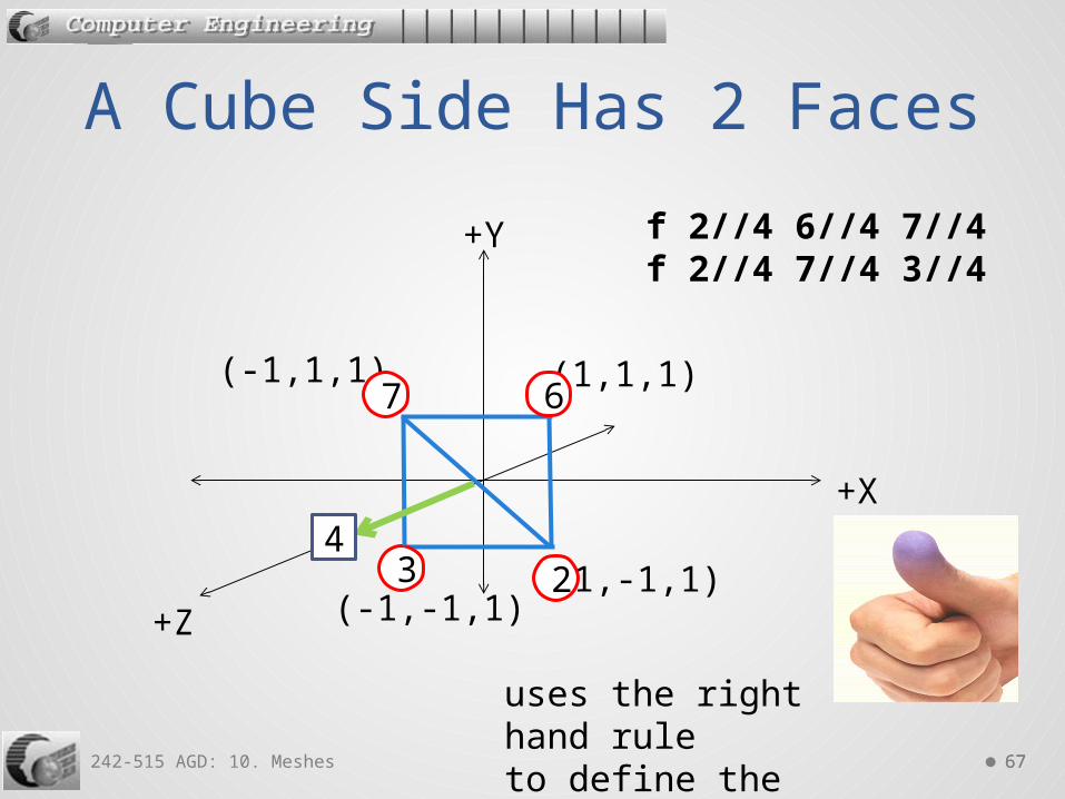
A Cube Side Has 2 Faces
+X
+Z
+Y
(1,-1,1)
(1,1,1)(-1,1,1)
23(-1,-1,1)
67
4
f 2//4 6//4 7//4f 2//4 7//4 3//4
uses the right hand ruleto define the front face
242-515 AGD: 10. Meshes 6868
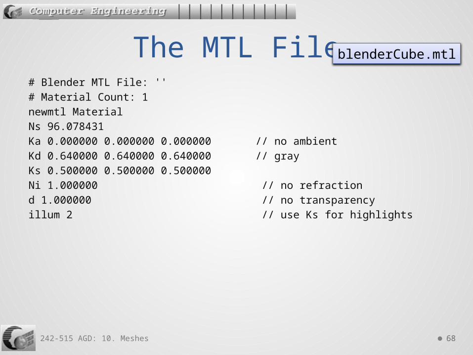
# Blender MTL File: ''# Material Count: 1newmtl MaterialNs 96.078431Ka 0.000000 0.000000 0.000000 // no ambientKd 0.640000 0.640000 0.640000 // grayKs 0.500000 0.500000 0.500000Ni 1.000000 // no refractiond 1.000000 // no transparencyillum 2 // use Ks for highlights
The MTL File blenderCube.mtl

242-515 AGD: 10. Meshes 6969
Spatial model = assetManager.loadModel("models/blenderCube.obj");model.scale(0.5f);
Loaded by jME
Cube's sidesare scaled to0.5 units
GridZoneLoad.java

242-515 AGD: 10. Meshes 7070
• It's easy to modify the MTL file:Kd 0.54 0.89 0.63 // jade (see Part 9, sec 6.1)
Modifying the Material
Cube's diffusereflection isnow jade
242-515 AGD: 10. Meshes 7171
• The OBJ format is fully explained at:o http://local.wasp.uwa.edu.au/~pbourke/dataformats/obj/
• The MTL format:o http://local.wasp.uwa.edu.au/~pbourke/dataformats/mtl/
Full OBJ and MTL Details

242-515 AGD: 10. Meshes 7272
• The use of meshes composed of verticies, faces, edges, and normals is the standard way of creating models in computer graphics.
• There are other approaches, such as:o Constructive Solid Geometry (CSG)o Metaballs
10. Other Geometric Models

242-515 AGD: 10. Meshes 7373
• CSG builds a shape using Boolean operators (union, difference, intersection) on primitive shapes (cubes, spheres, etc)o available in the Unreal engine
Constructive Solid Geometry (CSG)
union:cube + sphere
difference: cube - sphere
intersection: cube ∩ sphere

242-515 AGD: 10. Meshes 7474
• Used to model organic shapes and fluids. • A ball has a fuzzy region around it. • When two ball come near to each other, their
fuzzy regions start merging.
Metaballs
the red and blue metaballs come together