2.4 tape head technology
TRANSCRIPT

© 2012 Information Storage Industry Consortium – All Rights Reserved International Magnetic Tape Storage Roadmap Reproduction Without Permission is Prohibited May 2012
107
2.4 Tape Head Technology
Participants
Bob Biskeborn, IBM (Team Co-Leader) Larry Neumann, Quantum (Team Co-Leader) C. Singh Bhatia, National University of Singapore Gary Decad, IBM Richard Dee, Quantum Robert Fontana, IBM Paul Frank, INSIC Larry Hansen, Hewlett-Packard Pierre-Olivier Jubert, IBM Calvin Lo, IBM Kevin McKinstry, Oracle Marty Schmalhorst, Oracle Osamu Shimizu, Fujifilm Fred Spada, University of California, San Diego
2.4.1 Introduction Heads used for tape and hard disk recording are comprised of thin film read and write transducers fabricated on hard ceramic wafers, usually AlTiC (aluminum oxide - titanium carbide). Finished wafers are subsequently fashioned into heads suitable for reading from and writing to the moving medium. During this fabrication process, heads are lapped to achieve the necessary transducer dimensions and to provide a nanometer scale smooth finish to allow small head-medium spacing. For many years, tape transducer designs have been a generation or so behind their disk head counterparts [1]. For example, giant magnetoresistive (GMR) sensors were introduced in 1997 in HDDs but were not deployed in tape drive products until 2008 (IBM TS1130) [2, 3]. Tunneling magnetoresistive (TMR) sensors are used exclusively in current HDDs, but have not yet appeared in tape drives. This is primarily because magnetic head requirements are tied to areal density, and hard disk areal densities are currently > 200 times higher than for tape. This is largely related to the differences between tape and disk media. For example, tape is particulate, disks are sputtered thin films, etc. Areal density trends are shown in Section 2.1 of this Roadmap. It is apparent that in 10 years tape areal density will still be catching up to today’s HDD areal density. Thus, HDD sensor technologies are expected to satisfy the requirements for tape heads as outlined in this Roadmap. That HDD engineers have developed transducers years in advance of when they will be needed for tape suggests that tape engineers and scientists may have an easier time with heads. While certainly beneficial, just having sensitive transducers is not the whole story. For example, to achieve the data rates shown in the Roadmap, tape heads will continue to employ multiple simultaneously operating channels, and in increasing numbers. Thus, where disk slider yield is based on having a single functional pair of read-write transducers, tape head die yield is based on having all transducers (34 for today’s LTO head) fully functional – one bad transducer means the entire die is bad. Another aspect unique to tape heads is a need for precise alignment between the write and read transducer arrays on a die. This affects, for example, the
© 2012 Information Storage Industry Consortium – All Rights Reserved International Magnetic Tape Storage Roadmap Reproduction Without Permission is Prohibited May 2012
108
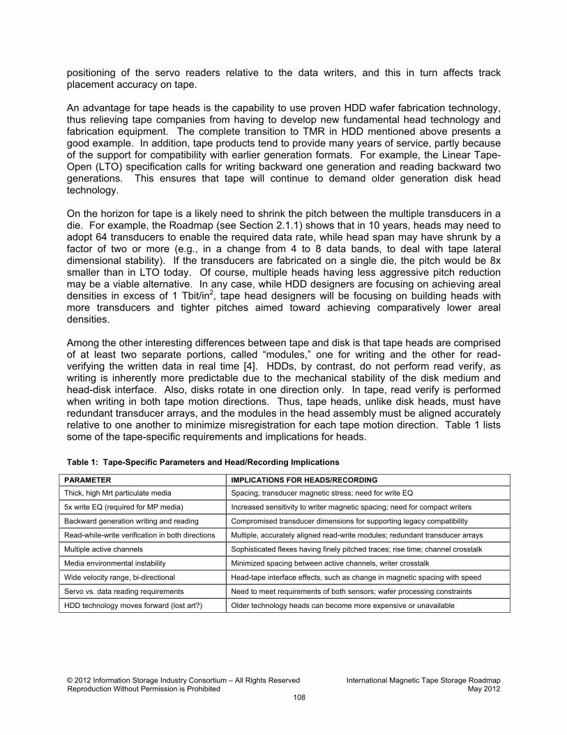
positioning of the servo readers relative to the data writers, and this in turn affects track placement accuracy on tape. An advantage for tape heads is the capability to use proven HDD wafer fabrication technology, thus relieving tape companies from having to develop new fundamental head technology and fabrication equipment. The complete transition to TMR in HDD mentioned above presents a good example. In addition, tape products tend to provide many years of service, partly because of the support for compatibility with earlier generation formats. For example, the Linear Tape-Open (LTO) specification calls for writing backward one generation and reading backward two generations. This ensures that tape will continue to demand older generation disk head technology. On the horizon for tape is a likely need to shrink the pitch between the multiple transducers in a die. For example, the Roadmap (see Section 2.1.1) shows that in 10 years, heads may need to adopt 64 transducers to enable the required data rate, while head span may have shrunk by a factor of two or more (e.g., in a change from 4 to 8 data bands, to deal with tape lateral dimensional stability). If the transducers are fabricated on a single die, the pitch would be 8x smaller than in LTO today. Of course, multiple heads having less aggressive pitch reduction may be a viable alternative. In any case, while HDD designers are focusing on achieving areal densities in excess of 1 Tbit/in2, tape head designers will be focusing on building heads with more transducers and tighter pitches aimed toward achieving comparatively lower areal densities. Among the other interesting differences between tape and disk is that tape heads are comprised of at least two separate portions, called “modules,” one for writing and the other for read-verifying the written data in real time [4]. HDDs, by contrast, do not perform read verify, as writing is inherently more predictable due to the mechanical stability of the disk medium and head-disk interface. Also, disks rotate in one direction only. In tape, read verify is performed when writing in both tape motion directions. Thus, tape heads, unlike disk heads, must have redundant transducer arrays, and the modules in the head assembly must be aligned accurately relative to one another to minimize misregistration for each tape motion direction. Table 1 lists some of the tape-specific requirements and implications for heads.
Table 1: Tape-Specific Parameters and Head/Recording Implications
PARAMETER IMPLICATIONS FOR HEADS/RECORDING
Thick, high Mrt particulate media Spacing; transducer magnetic stress; need for write EQ
5x write EQ (required for MP media) Increased sensitivity to writer magnetic spacing; need for compact writers
Backward generation writing and reading Compromised transducer dimensions for supporting legacy compatibility
Read-while-write verification in both directions Multiple, accurately aligned read-write modules; redundant transducer arrays
Multiple active channels Sophisticated flexes having finely pitched traces; rise time; channel crosstalk
Media environmental instability Minimized spacing between active channels, writer crosstalk
Wide velocity range, bi-directional Head-tape interface effects, such as change in magnetic spacing with speed
Servo vs. data reading requirements Need to meet requirements of both sensors; wafer processing constraints
HDD technology moves forward (lost art?) Older technology heads can become more expensive or unavailable
© 2012 Information Storage Industry Consortium – All Rights Reserved International Magnetic Tape Storage Roadmap Reproduction Without Permission is Prohibited May 2012
109
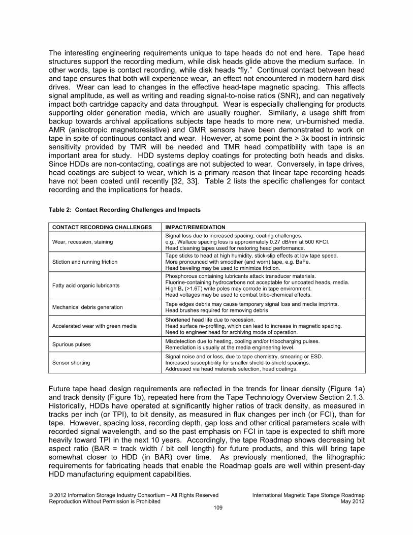
The interesting engineering requirements unique to tape heads do not end here. Tape head structures support the recording medium, while disk heads glide above the medium surface. In other words, tape is contact recording, while disk heads “fly.” Continual contact between head and tape ensures that both will experience wear, an effect not encountered in modern hard disk drives. Wear can lead to changes in the effective head-tape magnetic spacing. This affects signal amplitude, as well as writing and reading signal-to-noise ratios (SNR), and can negatively impact both cartridge capacity and data throughput. Wear is especially challenging for products supporting older generation media, which are usually rougher. Similarly, a usage shift from backup towards archival applications subjects tape heads to more new, un-burnished media. AMR (anisotropic magnetoresistive) and GMR sensors have been demonstrated to work on tape in spite of continuous contact and wear. However, at some point the > 3x boost in intrinsic sensitivity provided by TMR will be needed and TMR head compatibility with tape is an important area for study. HDD systems deploy coatings for protecting both heads and disks. Since HDDs are non-contacting, coatings are not subjected to wear. Conversely, in tape drives, head coatings are subject to wear, which is a primary reason that linear tape recording heads have not been coated until recently [32, 33]. Table 2 lists the specific challenges for contact recording and the implications for heads.
Table 2: Contact Recording Challenges and Impacts
Future tape head design requirements are reflected in the trends for linear density (Figure 1a) and track density (Figure 1b), repeated here from the Tape Technology Overview Section 2.1.3. Historically, HDDs have operated at significantly higher ratios of track density, as measured in tracks per inch (or TPI), to bit density, as measured in flux changes per inch (or FCI), than for tape. However, spacing loss, recording depth, gap loss and other critical parameters scale with recorded signal wavelength, and so the past emphasis on FCI in tape is expected to shift more heavily toward TPI in the next 10 years. Accordingly, the tape Roadmap shows decreasing bit aspect ratio (BAR = track width / bit cell length) for future products, and this will bring tape somewhat closer to HDD (in BAR) over time. As previously mentioned, the lithographic requirements for fabricating heads that enable the Roadmap goals are well within present-day HDD manufacturing equipment capabilities.
CONTACT RECORDING CHALLENGES IMPACT/REMEDIATION
Wear, recession, staining Signal loss due to increased spacing; coating challenges. e.g., Wallace spacing loss is approximately 0.27 dB/nm at 500 KFCI. Head cleaning tapes used for restoring head performance.
Stiction and running friction Tape sticks to head at high humidity, stick-slip effects at low tape speed. More pronounced with smoother (and worn) tape, e.g. BaFe. Head beveling may be used to minimize friction.
Fatty acid organic lubricants
Phosphorous containing lubricants attack transducer materials. Fluorine-containing hydrocarbons not acceptable for uncoated heads, media. High Bs (>1.6T) write poles may corrode in tape environment. Head voltages may be used to combat tribo-chemical effects.
Mechanical debris generation Tape edges debris may cause temporary signal loss and media imprints. Head brushes required for removing debris
Accelerated wear with green media Shortened head life due to recession. Head surface re-profiling, which can lead to increase in magnetic spacing. Need to engineer head for archiving mode of operation.
Spurious pulses Misdetection due to heating, cooling and/or tribocharging pulses. Remediation is usually at the media engineering level.
Sensor shorting Signal noise and or loss, due to tape chemistry, smearing or ESD. Increased susceptibility for smaller shield-to-shield spacings. Addressed via head materials selection, head coatings.

© 2012 Information Storage Industry Consortium – All Rights Reserved International Magnetic Tape Storage RoadmapReproduction Without Permission is Prohibited May 2012
110
Figure 1a: Tape Linear Density Trend
Figure 1b: Tape Track Density Trend
For all the demands placed on heads and other aspects of tape systems, the strains on HDDand NAND flash may be even more daunting [5]. While tape areal density is projected to growat roughly 33% per year in this period, lithographic and other fundamental challenges for HDD
Linear Tape Products
Roadmap Projections
Linear Tape Products
Roadmap Projections
(8% per year)
(13% per year)
(19% per year)
(23% per year)
© 2012 Information Storage Industry Consortium – All Rights Reserved International Magnetic Tape Storage Roadmap Reproduction Without Permission is Prohibited May 2012
111
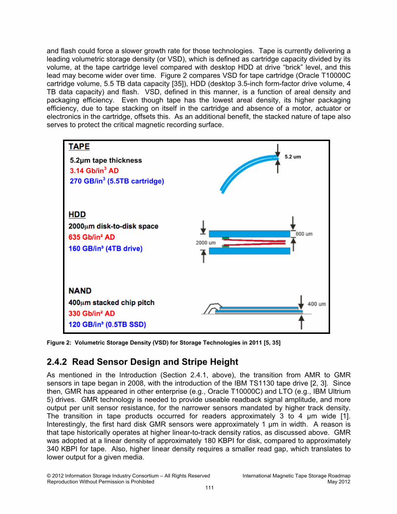
and flash could force a slower growth rate for those technologies. Tape is currently delivering a leading volumetric storage density (or VSD), which is defined as cartridge capacity divided by its volume, at the tape cartridge level compared with desktop HDD at drive “brick” level, and this lead may become wider over time. Figure 2 compares VSD for tape cartridge (Oracle T10000C cartridge volume, 5.5 TB data capacity [35]), HDD (desktop 3.5-inch form-factor drive volume, 4 TB data capacity) and flash. VSD, defined in this manner, is a function of areal density and packaging efficiency. Even though tape has the lowest areal density, its higher packaging efficiency, due to tape stacking on itself in the cartridge and absence of a motor, actuator or electronics in the cartridge, offsets this. As an additional benefit, the stacked nature of tape also serves to protect the critical magnetic recording surface.
Figure 2: Volumetric Storage Density (VSD) for Storage Technologies in 2011 [5, 35] 2.4.2 Read Sensor Design and Stripe Height As mentioned in the Introduction (Section 2.4.1, above), the transition from AMR to GMR sensors in tape began in 2008, with the introduction of the IBM TS1130 tape drive [2, 3]. Since then, GMR has appeared in other enterprise (e.g., Oracle T10000C) and LTO (e.g., IBM Ultrium 5) drives. GMR technology is needed to provide useable readback signal amplitude, and more output per unit sensor resistance, for the narrower sensors mandated by higher track density. The transition in tape products occurred for readers approximately 3 to 4 µm wide [1]. Interestingly, the first hard disk GMR sensors were approximately 1 µm in width. A reason is that tape historically operates at higher linear-to-track density ratios, as discussed above. GMR was adopted at a linear density of approximately 180 KBPI for disk, compared to approximately 340 KBPI for tape. Also, higher linear density requires a smaller read gap, which translates to lower output for a given media.
5.2μm tape thickness
3.14 Gb/in3 AD
270 GB/in3 (5.5TB cartridge)
5.2 um
© 2012 Information Storage Industry Consortium – All Rights Reserved International Magnetic Tape Storage Roadmap Reproduction Without Permission is Prohibited May 2012
112
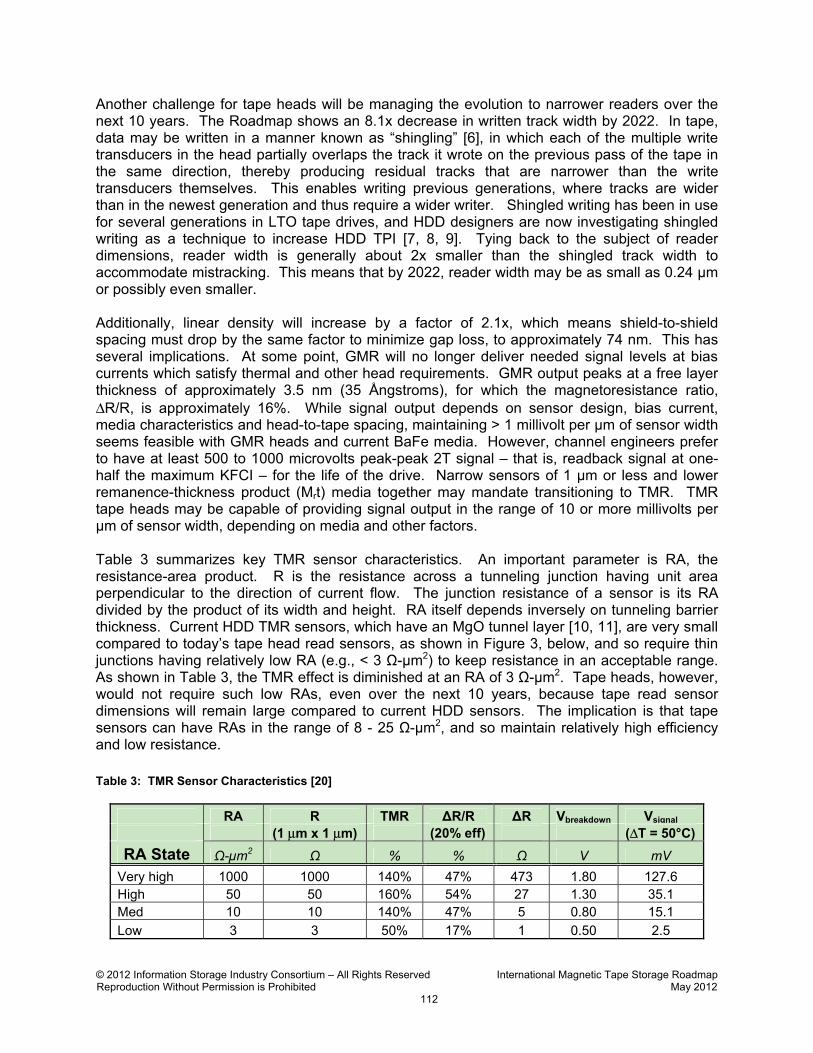
Another challenge for tape heads will be managing the evolution to narrower readers over the next 10 years. The Roadmap shows an 8.1x decrease in written track width by 2022. In tape, data may be written in a manner known as “shingling” [6], in which each of the multiple write transducers in the head partially overlaps the track it wrote on the previous pass of the tape in the same direction, thereby producing residual tracks that are narrower than the write transducers themselves. This enables writing previous generations, where tracks are wider than in the newest generation and thus require a wider writer. Shingled writing has been in use for several generations in LTO tape drives, and HDD designers are now investigating shingled writing as a technique to increase HDD TPI [7, 8, 9]. Tying back to the subject of reader dimensions, reader width is generally about 2x smaller than the shingled track width to accommodate mistracking. This means that by 2022, reader width may be as small as 0.24 µm or possibly even smaller. Additionally, linear density will increase by a factor of 2.1x, which means shield-to-shield spacing must drop by the same factor to minimize gap loss, to approximately 74 nm. This has several implications. At some point, GMR will no longer deliver needed signal levels at bias currents which satisfy thermal and other head requirements. GMR output peaks at a free layer thickness of approximately 3.5 nm (35 Ångstroms), for which the magnetoresistance ratio, ΔR/R, is approximately 16%. While signal output depends on sensor design, bias current, media characteristics and head-to-tape spacing, maintaining > 1 millivolt per µm of sensor width seems feasible with GMR heads and current BaFe media. However, channel engineers prefer to have at least 500 to 1000 microvolts peak-peak 2T signal – that is, readback signal at one-half the maximum KFCI – for the life of the drive. Narrow sensors of 1 µm or less and lower remanence-thickness product (Mrt) media together may mandate transitioning to TMR. TMR tape heads may be capable of providing signal output in the range of 10 or more millivolts per µm of sensor width, depending on media and other factors. Table 3 summarizes key TMR sensor characteristics. An important parameter is RA, the resistance-area product. R is the resistance across a tunneling junction having unit area perpendicular to the direction of current flow. The junction resistance of a sensor is its RA divided by the product of its width and height. RA itself depends inversely on tunneling barrier thickness. Current HDD TMR sensors, which have an MgO tunnel layer [10, 11], are very small compared to today’s tape head read sensors, as shown in Figure 3, below, and so require thin junctions having relatively low RA (e.g., < 3 Ω-µm2) to keep resistance in an acceptable range. As shown in Table 3, the TMR effect is diminished at an RA of 3 Ω-µm2. Tape heads, however, would not require such low RAs, even over the next 10 years, because tape read sensor dimensions will remain large compared to current HDD sensors. The implication is that tape sensors can have RAs in the range of 8 - 25 Ω-µm2, and so maintain relatively high efficiency and low resistance.
Table 3: TMR Sensor Characteristics [20]
RA R TMR ∆R/R ∆R Vbreakdown Vsignal (1 μm x 1 μm) (20% eff) (ΔT = 50°C)
RA State Ω-µm2 Ω % % Ω V mV
Very high 1000 1000 140% 47% 473 1.80 127.6 High 50 50 160% 54% 27 1.30 35.1 Med 10 10 140% 47% 5 0.80 15.1
Low 3 3 50% 17% 1 0.50 2.5

© 2012 Information Storage Industry Consortium – All Rights Reserved International Magnetic Tape Storage RoadmapReproduction Without Permission is Prohibited May 2012
113
Assuming that linear density increases according to the Roadmap, TMR will be required toaddress both decreasing sensor width and signal loss due to head recession. For example, by2022 the losses for a given sensor recession will be > 2x that of today. There are no TMR tapeproducts as of mid 2012, and compatibility with tape is not certain. Favoring TMR is theabsence of the thin, corrosion sensitive copper spacer used in GMR sensors. In addition, apublished report [12] suggests that “[TMR] heads have a remarkable resilience against[electrical over-stress].”
Another possibility for tape heads might be using TMR sensors in conjunction with a flux guidein a yoke head configuration [13, 14]. This would eliminate the presence of electrically activeelements at the head surface (spacing losses notwithstanding). The assumptions in Table 3 arethat 20% of the available flux from the transition traverses the sensor. This is reasonable if thesensor is at the tape-bearing surface between two shields. A yoke head has reduced fluxefficiency, but even if only 1% efficient, its signal level might still be 5 mV/µm. An alternative toTMR may be CPP current-perpendicular-to-the-plane GMR heads [15], currently an active areaof study for HDD. These have lower resistance for a given area than conventional CIP current-in-the-plane GMR heads and may also be attractive for tape head applications.
Figure 3: Tape Head Read Sensor Width Scaling over Time and Comparison to Current HDD TMR SensorDimensions (at approximately 50 nm x 50 nm, shown at the bottom of the figure). [See also Figure 9 inSection 2.4.9 for the 2012-2022 read sensor width dimensions]
A requirement for all future sensors is that stripe height and lapping tolerance will need todecrease to keep pace with decreasing sensor width. This is shown in Figure 3, where AMR is
= AMR= GMR= Transition from GMR to TMR= TMR
Sensor Width: 5.7 µm (½ the written track width)
StripeHeight
(roughlyto scale)
© 2012 Information Storage Industry Consortium – All Rights Reserved International Magnetic Tape Storage Roadmap Reproduction Without Permission is Prohibited May 2012
114
shown in blue, GMR in green and TMR (projected) in red. Sensor widths are ½ the INSIC Roadmap written track widths, and sensor heights are rough estimates based on historical trends. Today, stripe heights are approximately 1.0 µm with a typical tolerance of approximately +/- 25%. Optimum stripe height depends on thermal and magnetic utilization calculations, but narrow sensors having a high aspect ratio may exhibit noise due to ferromagnetic resonance within the free layer [16], as observed in narrow HDD heads. By 2022, optimal stripe height will be comparable to sensor width, as for HDD, and the total stripe height will be comparable to today’s lapping tolerances alone. Stripe heights will need to be controlled very precisely across the array of sensors in the head module. Techniques developed for HDD are not directly applicable to tape heads today, so new fabrication procedures may need to be developed. Compared to HDD sensors (as shown at the bottom of Figure 3), however, required dimensions are well within reach. Finally, there may be issues related to the 74 nm shield-to-shield spacing required by 2022. A well-known phenomenon in tape recording is conductive bridging across the read gap due to running tape over the head. Ten years ago, tape heads had 400 nm read gaps, but even these were not completely immune to bridging and the resultant electrical shorting of the sensor. Low ductility shield materials, such as CZT cobalt-zirconium-tantalum alloy or various laminated Fe/NiFe films, can help. In conventional GMR and AMR CIP heads, multiple bridge connections are required to degrade the readback signal. In contrast, TMR heads operate in CPP mode, where a single bridge event may potentially degrade readback. Protective coatings for GMR sensors have recently been introduced in some products [32, 33] and are actively being investigated [17]. These may become even more important for TMR heads, and research in the areas of tape head tribology and coatings must continue.
2.4.3 Pulse Width, User Bit Density and SNR Heads are designed to operate at areal densities commensurate with the capabilities of a specific type of medium, or types of media, depending on requirements for backward compatibility. Operating points establish read sensor shield-to-shield spacing and width, sensor bias current, and writer gap length and width. Beyond this, signal characteristics are determined primarily by the media magnetic properties and head-media separation. Therefore, a discussion of tape heads in some respects becomes a discussion of how to control head-media separation. Obviously, there are many important considerations, such as designing sensors to operate stably for multiple media generations which may have quite different Mrt values. In any case, a discussion of PW50 and SNR can help illuminate head design challenges. High bit density requires narrow pulse width (PW50) to enable resolving the bits. The ratio of PW50 to bit length is called “user bit density” (UBD). PW50 depends on reader shield-to-shield gap (g), head-media separation (d), which is the magnetic spacing between the transducers and the surface of the magnetic recording layer, magnetic coating thickness (δ), and transition parameter (a), via the expression shown in Table 4 [18, 19] below. Shield-to-shield gap is normally scaled with decreasing bit length to minimize gap loss. Target head-media separation is set to 2/3 times the bit length. Magnetic coating thickness is taken to be 2x the target head-media separation. An expression for the transition parameter a is shown in Table 4. In the Roadmap, bit length decreases approximately 14% per generation, corresponding to 8.0% CAGR in linear bit density. Calculated values for transition parameter and PW50 are given for each generation assuming that media remanence Mr and coercivity Hc are constant. The Media Section of this Roadmap (see Section 2.3.2) suggests that smaller particles will be needed to

© 2012 Information Storage Industry Consortium – All Rights Reserved International Magnetic Tape Storage Roadmap Reproduction Without Permission is Prohibited May 2012
115
Table 4: SNR and User Bit Density, Assuming Constant Hc
© 2012 Information Storage Industry Consortium – All Rights Reserved International Magnetic Tape Storage Roadmap Reproduction Without Permission is Prohibited May 2012
116
sustain continued improvement in media SNR by 2020. Accordingly, in 2020 Hc will increase due to the decrease in particle size, and this happens again in 2022. In this analysis, UBD does not change from generation to generation because g, a, d and δ are all assumed to scale with bit length, and PW50 is approximately 3.7 times the bit length. The implication is that effects which influence d and a must be managed carefully over time to ensure proper scaling. For example, higher Hc in 2020 may require higher Bs (saturation flux density) write pole materials. This is discussed in the section on Write Transducer Design (Section 2.4.5, below). Deployment of non-oriented BaFe media and, later, perpendicularly oriented media or even thin film media, may have implications for recording physics and the assumptions in Table 4. For example, MP media requires write equalization (WEQ), which is a recording process for linearizing the readback signal over the spectrum of recorded wavelengths. It also serves to reduce PW50. It does this by adding extra transitions to the low frequency content of the incoming waveform at a linear density too high for the reader to detect. This has the effect of reducing the readback amplitude at low frequency, while not altering the high frequency content, thus effectively linearizing the readback. The random orientation of the magnetic particles in non-oriented BaFe media diminishes the effectiveness of WEQ, which is thus not required for this medium. Two tape products that use BaFe media shipped in 2011 (IBM TS1140 and Oracle T10000C). The trend of constant UBD shown in Table 4 does not take into account the fact that the recording channel may be improved over the same period, as suggested in the Recording Channel Electronics Section (see Section 2.5) of the Roadmap. Developments that lead to even higher UBD may require more sophisticated channels for decoding the data. In any case, head designs will be adapted to work optimally with future media and operating points. From this perspective, tape head transducer design is, once again, likely to follow trends similar to HDD. Signal-to-noise ratio is a critical parameter in magnetic recording. Broadband SNR (BBSNR) decreases as the square root of read sensor width via the expression shown in Table 4, where w1 represents the read track width in 2012 and w2 the reduced future read track width, or 3.0 dB for each halving of reader width. Track density is assumed to grow approximately 1.5x each two-year generation (23.3% CAGR). Thus, BBSNR decreases 1.8 dB each generation, as shown in the table. This represents a 9.1 dB drop in SNR due to reader width on the assumption of approximately a constant number of particles in the bit cell. SNR depends not only on reader width, but also on bit density and head-media spacing, as well as properties of the medium itself, as indicated in Table 4. The present scaling assumptions predict a 14 dB drop in BBSNR by 2022, even with the assumption of smaller particles starting in 2020 [21, 22]. This is shown in Figure 4 (in blue), for both the case where track width (TW) is fixed and the case where TW varies according to the Roadmap, along with the two companion cases (shown in red) where a also scales with linear density, as assumed in Table 4. The Recording Media Technology section of this Roadmap (see Section 2.3) explains that, prior to 2020, improvements in particle orientation and improvements in detection channels will enable the projected operating points. By 2020, smaller particles and higher Hc will be needed to achieve the target areal densities.

© 2012 Information Storage Industry Consortium – All Rights Reserved International Magnetic Tape Storage Roadmap Reproduction Without Permission is Prohibited May 2012
117
Figure 4: The Change in BBSNR vs. 2T Linear Density at Each Generation in the Roadmap [21, 22] The growth in data rate projected over the next 10 years means that the read channel bandwidth will also increase. This implies that the thermal (or Nyquist) noise in the head may
also increase according to the familiar expression: Vn = (4kTR ∆f)1/2, where k is Boltzmann’s constant, T is the sensor temperature in Kelvin, R is sensor resistance and ∆f is the 2T signal bandwidth. If resistance is constant over generations, then the ratio of 2T signal to Nyquist noise declines unless the 2T amplitude scales with signal bandwidth. Channel engineers typically want this ratio to be approximately 30dB or higher. For resistances of the order of 100 ohms and amplitudes of at least 1 mV, Nyquist noise has not been a significant issue, but may become a more important consideration for future heads having smaller reader track widths.
2.4.4 Wear, Spacing and Friction In order to achieve the highest possible areal density, head designers must ensure that reading and writing transducers remain in close proximity to the tape magnetic surface as the head wears. This is because, for a given head and tape, both signal amplitude and BBSNR decline with increasing head-media separation, and the effect is more pronounced at higher signal frequencies. Figure 5 shows computed BBSNR vs. spacing at 400 KFCI for 3 cases: writer magnetic spacing dW fixed; reader magnetic spacing dR fixed; and both spacing values changing together. Writing and reading functions may be performed by transducers fabricated in physically separate head modules (such as in the TS1140 and T10000C), which may show

© 2012 Information Storage Industry Consortium – All Rights Reserved International Magnetic Tape Storage Roadmap Reproduction Without Permission is Prohibited May 2012
118
different wear characteristics. For Figure 5, the calculations take into account the dependence of the transition parameter on spacing [23]. The data show that the losses in SNR become significant at higher spacing and are greater for reader than for writer spacing. While scaling is needed to enable the areal densities in the Roadmap, controlling wear is needed for scaling to remain valid.
Figure 5: The Change in BBSNR with respect to Magnetic Spacing d for 400 KFCI Recording and Reading with 65 nm Thick Non-oriented BaFe Medium. Write Gap = 200 nm. Reader Shield-to-Shield = 100 nm [23] Media thickness, surface roughness and head coatings all contribute to static magnetic spacing. However, other effects, such as stain buildup on the head, re-profiling of the head contour by the media, and wear-induced pole tip recession may also play a role. Maintaining control of head-media spacing over the life of the drive is an important consideration for tape. As mentioned in the Introduction (Section 2.4.1), heads may be especially susceptible to wear from what is termed “green” media, which is tape that has had little to no exposure in a drive. Green tapes may produce more head wear due to a higher density of un-burnished asperities. Fortunately, a few full file passes of a tape may be enough to burnish the asperities, depending on the design and state of wear of the head. However, archiving operations, in which tapes are written once and stored, may expose drives to a constant supply of green tapes, and the prevalence of archiving-only applications may expand in the coming years. A possible area of additional research is to seek better understanding of the interaction between head materials and tape components, such as asperities and lubricants, with the goal of finding materials that are compatible and minimally degrading to heads. Media will have to become smoother to minimize magnetic spacing. But transitioning to ever-smoother media may mean increased static and running friction at the head-tape interface. This is particularly evident with BaFe media introduced in 2011. Static friction can lead to transport stalls or worse. Running tape velocity variations, caused by stick-slip effects, can disrupt data detection, especially at low tape speeds (< 2 m/s) [24, 34]. A means for reducing friction is to round, or “bevel,” the non-functional portions of the head surface. This was introduced in 2010
25 30 35 40 45 50 55 60 65-15
-10
-5
0
d (nm)
ΔBB
SN
R (
dB
)
d=dW
=dR
d=dW
, dR
=29nm
d=dR
; dW
=29nm

© 2012 Information Storage Industry Consortium – All Rights Reserved International Magnetic Tape Storage Roadmap Reproduction Without Permission is Prohibited May 2012
119
in the IBM LTO-5 drive offerings. However, newer generation BaFe media are expected to be smoother and beveling may not be adequate. This could call into question the viability of the air-skiving arrangement used in modern linear tape drives, in which sharp, over-wrapped edges of the head’s flat surface "scrape" or "skive" off the boundary layer of air which would otherwise be carried by the tape into its interface with the head and thus increase the head-media separation. Non-skiving designs may need to be developed, thereby mandating a re-engineering of the head-tape interface. Another aspect of head tribology is the role of media lubricants and other components that can chemically affect the head-tape interface. For example, phosphorus is long suspected to contribute to pitting of the sputtered alumina used in tape heads for electrical insulation, yet it is still found in modern linear tapes. There is evidence that the acid-to-ester ratio in tape lubricants, which are necessary for controlling friction between head and tape, affects wear and pitting [25]. A complicating factor is that friction and wear processes may be affected by relative humidity and may also depend on the electrical potentials in the head. Read sensors are electrically biased and so operate at a fixed potential relative to ground. To help control the tribology, the AlTiC substrate may also be voltage biased. The relationships are complex and worthy of on-going investigation. The above discussion emphasizes that managing media roughness, wear and friction is an important area worthy of further investigation. Another interesting subject for future study is non-skiving head-tape interfaces. For example, active spacing compensation, used in HDD heads, might be possible for tape heads, but wear due to tape contact would be a primary concern. 2.4.5 Write Transducer Design Future particulate media will have smaller values of the thermal-stability parameter KuV/kT (where Ku is the anisotropy constant, V is particle volume, k is Boltzmann’s constant, and T is the absolute temperature), and this will result in a "dynamic" coercivity according to the following expression [26]:
Hc(t) = H01 – [(kT/KuV)ln(f0t)]n
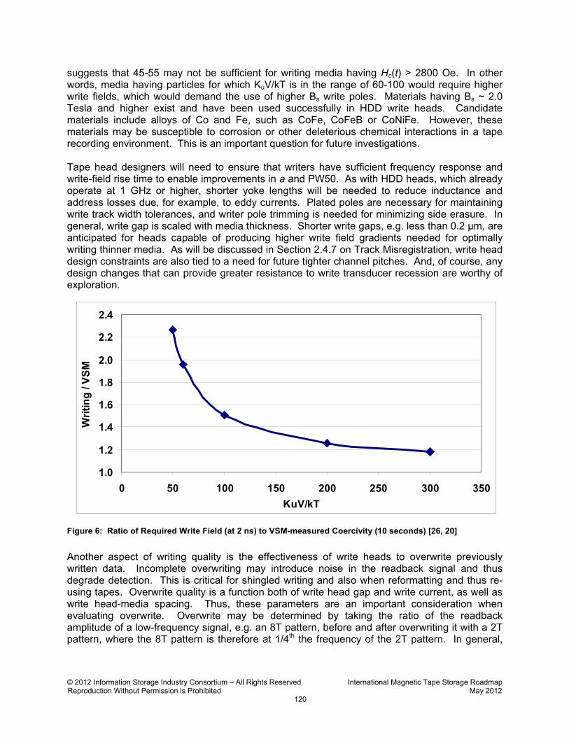
Here, H0 is the coercivity (~Ku/Ms, where Ms is the saturation magnetization), f0 is the applied frequency (approximately 1 GHz), t is the time scale of the applied field, and n ~ 0.7. Thus, there is a larger change in effective coercivity for smaller KuV/kT, as can be seen in Figure 6, which shows the ratio of “writing coercivity” at 2 ns to vibrating sample magnetometer (VSM) coercivity at 10 seconds. From the data in this figure, future media having smaller KuV/kT ratio may require higher writing field than that based on the statically determined H0 value for the medium. A conventional guideline is that KuV/kT must be > 60 for archival media stability, implying that the writing/VSM coercivity ratio, Hc(t)/H0, could climb to nearly 1.8. This means that write heads would need to deliver up to 1.8 times the field needed for legacy particulate media having the same static coercivity H0. This has implications for write head design. The nickel-iron alloy which is comprised of 45% Ni and 55% Fe (“45-55”) has been used for write poles in tape heads for years [36]. From a tribology standpoint, it is a viable candidate for future tape heads. Magnetically, however, the saturation induction Bs of 45-55 is 16 kG. Write heads having 45-55 poles are capable of developing write fields near the middle of the write gap > 8000 Oe at saturation. Using an approximate rule of thumb that head gap field must be at least approximately three times H0
© 2012 Information Storage Industry Consortium – All Rights Reserved International Magnetic Tape Storage Roadmap Reproduction Without Permission is Prohibited May 2012
120
suggests that 45-55 may not be sufficient for writing media having Hc(t) > 2800 Oe. In other words, media having particles for which KuV/kT is in the range of 60-100 would require higher write fields, which would demand the use of higher Bs write poles. Materials having Bs ~ 2.0 Tesla and higher exist and have been used successfully in HDD write heads. Candidate materials include alloys of Co and Fe, such as CoFe, CoFeB or CoNiFe. However, these materials may be susceptible to corrosion or other deleterious chemical interactions in a tape recording environment. This is an important question for future investigations. Tape head designers will need to ensure that writers have sufficient frequency response and write-field rise time to enable improvements in a and PW50. As with HDD heads, which already operate at 1 GHz or higher, shorter yoke lengths will be needed to reduce inductance and address losses due, for example, to eddy currents. Plated poles are necessary for maintaining write track width tolerances, and writer pole trimming is needed for minimizing side erasure. In general, write gap is scaled with media thickness. Shorter write gaps, e.g. less than 0.2 μm, are anticipated for heads capable of producing higher write field gradients needed for optimally writing thinner media. As will be discussed in Section 2.4.7 on Track Misregistration, write head design constraints are also tied to a need for future tighter channel pitches. And, of course, any design changes that can provide greater resistance to write transducer recession are worthy of exploration.
Figure 6: Ratio of Required Write Field (at 2 ns) to VSM-measured Coercivity (10 seconds) [26, 20]
Another aspect of writing quality is the effectiveness of write heads to overwrite previously written data. Incomplete overwriting may introduce noise in the readback signal and thus degrade detection. This is critical for shingled writing and also when reformatting and thus re-using tapes. Overwrite quality is a function both of write head gap and write current, as well as write head-media spacing. Thus, these parameters are an important consideration when evaluating overwrite. Overwrite may be determined by taking the ratio of the readback amplitude of a low-frequency signal, e.g. an 8T pattern, before and after overwriting it with a 2T pattern, where the 8T pattern is therefore at 1/4th the frequency of the 2T pattern. In general,
1.0
1.2
1.4
1.6
1.8
2.0
2.2
2.4
0 50 100 150 200 250 300 350
KuV/kT
Wri
tin
g /
VS
M

© 2012 Information Storage Industry Consortium – All Rights Reserved International Magnetic Tape Storage Roadmap Reproduction Without Permission is Prohibited May 2012
121
overwrite ratios of 25 - 30 dB or greater are achieved and should be sustainable over the next 10 years with proper head design. A few years ago, hard disks transitioned to perpendicularly oriented media, which has a magnetically soft underlayer below the primary magnetic storage layer. This has stimulated speculation that tape media may also need to transition to perpendicular media, although most likely without a soft underlayer. At the bit densities envisioned in the tape Roadmap, traditional “ring” heads should have adequate perpendicular fields to record perpendicularly oriented BaFe media.
2.4.6 Data Rate and Interconnects An engineering aspect common to all magnetic recording heads relates to the interconnections between write and read electronics on the drive circuit board and the respective transducers. Hard disks have put the preamplifier “chip-on-the-flex” to minimize signal propagation length, but heat generation and the weight of a multi-channel chip needed for a tape drive tend to discourage this approach. As a result, tape head flex circuits are typically substantially longer than in HDDs. And as mentioned in the Introduction (Section 2.4.1), tape heads have multiple transducers operating in parallel to achieve target data rates. This is because simply increasing tape speed is not feasible due to limitations imposed by the track-following servo bandwidth, motor and guide bearings, tape pack air entrainment, etc. Thus, tape head interconnects carry many more channels than their HDD counterparts. For example, the flex circuit for an LTO head die contains 16 pairs of write lines, 16 pairs of read lines, plus two extra pairs for servo readers. And each head contains two modules and thus two flex circuits. During writing, all 16 transducers are operating, and the noise arising from the writer lines must be isolated from the reader lines such that the spurious noise pickup is approximately 30 dB or better below the read signal level. Having a relatively large number of traces may adversely affect interconnect stiffness. This may, in turn, affect tracking performance. Thus, managing the growing number of transducers and connections is not trivial. This is an area that needs attention and investigation of possible alternatives. For example, according to the Roadmap, heads may need 64 channels by 2022, or 4 times the number of channels in today’s LTO heads. Figure 7 shows a chip image of an LTO head, where each channel is comprised of a reader-writer pair. Squeezing 4x the number of devices and connections into this space could be challenging. Apart from the difficulties of fabricating such a structure, there are other concerns, such as signal interference in the interconnect cables. Separating reading and writing functions into dedicated head modules addresses this, but at the expense of requiring additional components. Even so, this effectively reduces the number of connections to each module by about half.
Figure 7: Plane View of LTO Chip Image Showing 16 Data Tracks, 2 Servo Readers and Connection Pads (at top) [5]
Beyond the packaging aspects, interconnects must provide the proper impedance to the write drivers and read preamplifiers. Requiring a large number of traces in a limited space constrains trace geometries. Tape head cables are typically built from copper clad Kapton base films using a subtractive process. Cable resistance and impedance must be designed within the limitations
© 2012 Information Storage Industry Consortium – All Rights Reserved International Magnetic Tape Storage Roadmap Reproduction Without Permission is Prohibited May 2012
122
of the process. An area of future work would be looking into ways of overcoming these limitations. For example, additive copper cable processing could enable tighter trace geometries and tolerances.
2.4.7 Track Misregistration and Crosstalk Effects The active transducers in modern linear tape heads are clustered together into a span no more than either 1/4th (LTO, see Figure 7) or 1/8th (T10000C) the width of the tape. This is done to minimize misregistration between head tracks and previously written tape tracks caused by environmental changes. For example, head dimensions change with temperature, so head span at the time of recording may not be the same as when the wafer was built in the temperature-controlled wafer facilities. The span between servo readers in an LTO head is nominally 2.8689 mm, as built in a wafer fab at 20 °C. But in use in a tape drive at 40 °C, the span will be more than 0.4 µm larger. This is comparable to the Roadmap’s 2018 projection for reader transducer width alone. Moreover, the tape width itself may change with temperature, humidity and tension. As mentioned, this drives a potential need to shrink the span between the outermost head transducers over the coming decade as track density increases. More channels and reduced total span means that the pitch between transducers may have to drop by 4x or more. This leaves less room for read transducer hard bias magnets and leads. Write transducer footprints as small as 20 to 30 μm for spiral coil designs, or to as low as 15 to 20 μm for helical write coil designs, may be possible, but maintaining an adequate number of write coil turns along with shorter yokes may mean too few coil turns. For example, tape head writers typically have 10 or more turns, compared to 3 or fewer for HDD writers, which carry much higher currents than tape head writers. In addition, closely spaced writers can exhibit writer to writer crosstalk, a phenomenon that alters timing between recorded transitions [27] and degrades performance. There are already means available for controlling or cancelling head-tape misregistration. Helical scan tape recording has relied on azimuthally-oriented track shingling to reject off-track transitions on readback. However, this requires track angles of at least 30 degrees for adequate rejection [28], and this is not easy to implement in a linear tape drive. Another approach, called “Adjacent Track Recording,” was pioneered by O-MASS [29] but has a drawback of being sensitive to mistracking caused by tape skewing and also is not amenable to multi-product family architecture, in which track density increases incrementally from generation to generation. Yet another approach [30] involves mounting the head in the drive slightly rotated and then making small angular adjustments to correct the projected head span. Each approach requires a change in the manner in which linear drives record data, and a consequence of this is loss of backward compatibility. The current methodology of linear serpentine recording is likely to remain the preferred approach for at least a few years.
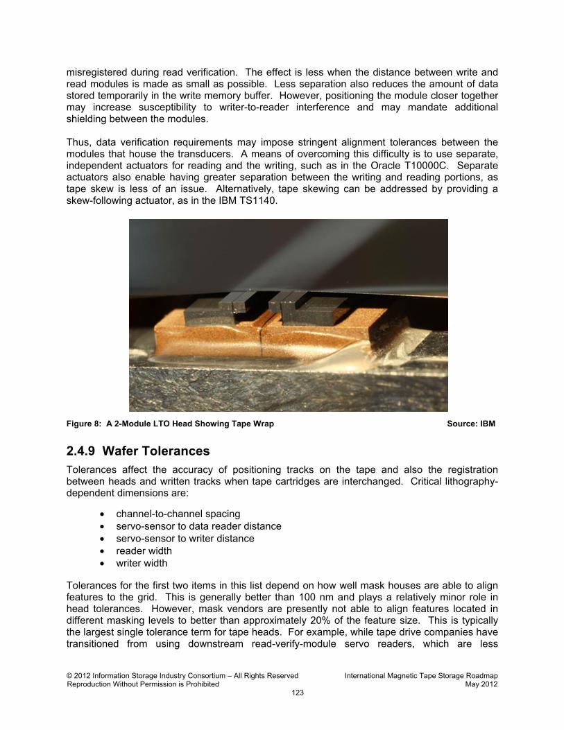
2.4.8 Head Requirements for Data Verification Since tape is used for backup and archive, most products read just-written data while still writing in order to verify that the information being stored was accurately recorded and will be retrievable [4]. Figure 8 shows a 2-module LTO head with tape wrapped across the surface. During writing, the downstream module verifies the data as it is being written by the upstream module. The drive needs to position the writers so that tracks are placed in the correct position and the readers are simultaneously kept on track. Problems may arise if the tape itself does not run perfectly horizontally across the head. This may cause readers to become temporarily
© 2012 Information Storage Industry Consortium – All Rights Reserved International Magnetic Tape Storage Roadmap Reproduction Without Permission is Prohibited May 2012
123
misregistered during read verification. The effect is less when the distance between write and read modules is made as small as possible. Less separation also reduces the amount of data stored temporarily in the write memory buffer. However, positioning the module closer together may increase susceptibility to writer-to-reader interference and may mandate additional shielding between the modules. Thus, data verification requirements may impose stringent alignment tolerances between the modules that house the transducers. A means of overcoming this difficulty is to use separate, independent actuators for reading and the writing, such as in the Oracle T10000C. Separate actuators also enable having greater separation between the writing and reading portions, as tape skew is less of an issue. Alternatively, tape skewing can be addressed by providing a skew-following actuator, as in the IBM TS1140.
Figure 8: A 2-Module LTO Head Showing Tape Wrap Source: IBM
2.4.9 Wafer Tolerances Tolerances affect the accuracy of positioning tracks on the tape and also the registration between heads and written tracks when tape cartridges are interchanged. Critical lithography-dependent dimensions are:
• channel-to-channel spacing • servo-sensor to data reader distance • servo-sensor to writer distance • reader width • writer width
Tolerances for the first two items in this list depend on how well mask houses are able to align features to the grid. This is generally better than 100 nm and plays a relatively minor role in head tolerances. However, mask vendors are presently not able to align features located in different masking levels to better than approximately 20% of the feature size. This is typically the largest single tolerance term for tape heads. For example, while tape drive companies have transitioned from using downstream read-verify-module servo readers, which are less

© 2012 Information Storage Industry Consortium – All Rights Reserved International Magnetic Tape Storage Roadmap Reproduction Without Permission is Prohibited May 2012
124
susceptible to noise from writers, to servo readers in the writing module (called “same gap servo”), track placement accuracy still depends on how well the servo readers are aligned to the writers in the writing module. Present and projected lithographic capabilities [31] suggest that the reader widths required will be controlled to ± 10% of the target values. Similarly, plated pole writer widths should be controllable to ± 10% of the target values. Requirements set forth in the section of this Roadmap on Tape Transport Technology (see Section 2.2.4) suggest that, if we continue on the evolutionary path of the past decade, tolerances will have to improve by at least this much over the next 10 years. Projected requirements for track pitch, reader width and head tolerances, based on achieving the track densities specified in the Roadmap, are shown in Figure 9. Here, the track pitch is simply calculated as the inverse of the track density projections shown in the Roadmap (see Section 2.1.1), reader width is assumed to be half the track pitch, and the head tolerances shown are assumed to be 5% of the track pitch (and thus 10% of the reader width). The average final written track width is assumed to be equal to the track pitch. Ultimately, tolerance requirements are considered in the wider context of tracking, media dimensional stability and the technologies discussed in other Sections of the Roadmap. Of less concern are shield-to-shield spacing, which is not dependent on photolithography, and write gap lengths, both of which should be controllable to better than ± 10%.
Figure 9: Track Pitch, Reader Width and Head Trackwidth Tolerance Requirements for Tape Heads
Verifying the dimensions of individual channels to sub-micrometer tolerances over hundreds to thousands of micrometers separation is not an easy task. Hence, establishing that heads are built as designed is not always feasible. Furthermore, achieving these tolerances may demand head fabrication equipment upgrades.
© 2012 Information Storage Industry Consortium – All Rights Reserved International Magnetic Tape Storage Roadmap Reproduction Without Permission is Prohibited May 2012
125
As a point of reference, the International Technology Roadmap for Semiconductors (ITRS) [31] has historically set lithography critical dimension 3σ at approximately 10% of the minimum feature size. Tape transducer processing controls are closer to those of NAND flash than of DRAM or MPU/Logic. Today, NAND flash devices are produced with 22 nm minimum features and the 3σ tolerance for this critical dimension is 2.3 nm. The NAND flash 3σ for overlay is 7.2 nm for small features, and overlay tolerance is approximately independent of the minimum size. In this example, overlay tolerance is > 3x the critical dimension tolerance. State-of-the-art mask technology delivers feature placements on a mask with an accuracy of 4.3 nm, which with a mask magnification factor of 4, translates to feature placement accuracy on a wafer of 1.1 nm. Caution must be used in applying this state of the art to tape heads, however. Specific points include cost of the tooling and the thickness limitation of the processed features:
• NAND processing uses state of the art, DUV 193 (deep ultraviolet lithography with 193 nm exposure wavelength), immersion photo tools with in situ resist apply and develop modules (with such tools costing > $25,000,000).
• Depth of field for this type of lithography tool limits processing to ultra-thin resists of approximately 100 nm in thickness.
However, when tape features approach the 250 nm read sensor track width range (10X larger than today’s NAND dimension), optical lithography tooling is expected to deliver 10% 3σ dimension control, i.e. 25 nm, and 20% 3σ overlay control, i.e. 50 nm. These precisions were realized 12 years ago in the HDD industry when comparable HDD heads were delivered for roughly 80 Gbit/in² areal densities. Tape heads have the added advantage of using optical lithography tooling that is 12 years more current than the tooling used by the HDD industry for these same dimensions.
2.4.10 Conclusion This Section of the Roadmap on Tape Head Technology has outlined many of the exciting head engineering challenges that lie ahead in the 10 year period envisioned in this Roadmap. The technology for fabricating future transducers exists, but needs to be specifically tailored for tape heads. Head architecture will be driven more by format, media dimensional stability, and tape transport capability. Control of head tolerances and head-media spacing will become increasingly demanding. Engineering of tape heads requires continued interaction and collaboration with the developers of the other parts of the tape drive and media system.
2.4.11 Suggested Areas for Further Research
Tribology
Friction between head and media is a critical issue for drive manufacturers. Determine causes of static and dynamic friction, experimentally and analytically. - Relation between friction and head materials, contour, surface finish…
- Stick-slip behavior with smooth media.
Head wear by green media is critical for archiving applications. Understand green media, the role of tape asperities and lubricants for head wear.
- Potential for a standard abrasive test for green vs. not-green media. - Changes in media as it evolves from “green” to not-green.
© 2012 Information Storage Industry Consortium – All Rights Reserved International Magnetic Tape Storage Roadmap Reproduction Without Permission is Prohibited May 2012
126
Tape lubricants are required but are implicated in staining, electrochemical reactions, etc.
Determine compatibility of the materials in heads and media such as lubricants, binders.
- Role of relative humidity (especially extremes) for tape head tribology. - Stain analysis to elucidate staining mechanisms.
Controlling electrochemistry with voltage bias appears critical to control transducer pitting.
Continue these efforts to establish broadly applicable guidelines for heads and media.
Lifetime corrosion protection may be needed for TMR by 2016. Evaluate wear and friction of head coatings with a goal of finding higher durability.
Spacing
Limiting head-tape spacing variation to around 2-3 nm is critical to achieve the Roadmap goals. Spacing is implicitly addressed in the Tribology initiatives outlined above. Assess potential for non-skiving air bearings and active spacing control.
Tracking and Tape Dimensional Instability
Tape dimensional instability will be a critical issue after about 2016. Quantify magnetic crosstalk in heads having writers on < 83 µm pitch. Research-level brainstorming of TDS management proposals.
Interconnects
Managing growing number of transducers and connections is critical. Evaluate feasibility of 64 channels in 2022 in a single head assembly. Assess opportunities for optical or other novel interconnects.
Writing
Writing high Hc particles in 2020 will require higher moment poles than presently used.
Evaluate high moment materials for use in tape heads. Assess impact with perpendicular media and heads.
2.4.12 References
1. Nibarger, J. P., “Transition from AMR to GMR Heads in Tape Recording,” presented at THIC Meeting in Boulder, CO, August 2007. Available online at: http://www.thic.org/pdf/August07/sun.Nibarger.pdf. Accessed May 2012.
2. “IBM Introduces the Industry's Fastest One Terabyte Storage Tape Drive,” News release, July 15, 2008, Available online at: http://www-03.ibm.com/press/us/en/pressrelease/24619.wss#release. Accessed May 2012.
3. Reine, D., “Lowering the TCO of the Data Center – IBM Innovates Tape Architecture … Again!” The Clipper Group Navigator, July 16, 2008, Available online at: ftp://public.dhe.ibm.com/storage/tape/clipper.pdf. Accessed May 2012.
4. Dee, R. H., “Magnetic Tape for Data Storage: An Enduring Technology,” Proceedings of the IEEE, Vol. 96, No. 11, November 2008, pp. 1775-1785.

© 2012 Information Storage Industry Consortium – All Rights Reserved International Magnetic Tape Storage Roadmap Reproduction Without Permission is Prohibited May 2012
127
5. Fontana Jr., R. E., Hetzler, S. R. and Decad, G., “Technology Roadmap Comparisons for TAPE, HDD, and NAND Flash: Implications for Data Storage Applications,” IEEE Trans. Magn., Vol. 48, No. 5, Part 1, May 2012, pp. 1692-1696.
6. Hellman, D.J., “Introducing Third-Generation LTO Tape Technology: IBM TotalStorage LTO Ultrium 3,” Technology Whitepaper, May 2005, Available online at: http://www.ess-direct.com/pdf/whitepapers/qualstar/IBM_LTO3_Technology_Whitepaper.pdf. Accessed May 2012. See particularly Appendix A.
7. Wood, R., et al., “The Feasibility of Magnetic Recording at 10 Terabits Per Square Inch on Conventional Media,” IEEE Trans. Magn., Vol. 45, No. 2, February 2009, pp. 917-923.
8. Shiroishi, Y., et al., “Future Options for HDD Storage,” IEEE Trans. Magn., Vol. 45, No. 10, October 2009, pp. 3816-3822.
9. Amer, A., et al., “Data Management and Layout for Shingled Magnetic Recording,” IEEE Trans. Magn., Vol 47, No. 10, October 2011, pp. 3691-3697.
10. Butler, W.H., et al., “Spin-dependent tunneling conductance of Fe/MgO/Fe sandwiches,” Phys. Rev. B 63 (5): 054416, January 2011.
11. Parkin, S.S.P., et al., “Giant tunnelling magnetoresistance at room temperature with MgO (100) tunnel barriers,” Nat. Mat. 3 (12), 2004: pp. 862–867
12. Guarisco, D., “Resilience of Tunneling Magnetoresistive Heads Against Electrical Overstress,” J. Applied Phys., Vol. 103, No. 7, April 2008.
13. Coehoorn, R., et al., “The electrical and magnetic response of yoke type read heads based on a magnetic tunnel junction,” IEEE Trans. Magn., Vol. 35, No. 5, September 1999, pp. 2586-2588.
14. Machida, K., et al., “Yoke-type TMR head with front-stacked gap for perpendicular magnetic recording,” Journal of Magnetism and Magnetic Materials, Vol. 235, October 2001, pp. 201-207.
15. Takagishi, M., et al., “The applicability of CPP-GMR heads for magnetic recording,” IEEE Trans. Magn., Vol. 38, No. 5, September 2002, pp. 2277-2282.
16. Klaassen, K.B., et al., “Broad-Band Noise Spectroscopy of Giant Magnetoresistive Read Heads,” IEEE Trans. Magn., Vol. 41, No. 7, , July 2005, pp. 2307-2317.
17. Rismani, E., et al., “Effect of pretreatment of Si interlayer by energetic C+ ions on the improved nanotribological properties of magnetic head overcoat,” Journal of Applied Physics, Vol. 111, No. 8, April 2012, 10 pages.
18. Bertram, H. Neal, Theory of Magnetic Recording, Cambridge University Press, April 1994, 376 pages.
19. Thurlings, L., “Statistical analysis of signal and noise in magnetic recording,” IEEE Trans. Magn., Vol. 16, No. 3, May 1980, pp. 507-513.
20. International Magnetic Tape Storage Roadmap, Information Storage Industry Consortium, September 2008, 149pp.
21. Jubert, P.-O., et al., “Noise and Recording Properties of Barium-Ferrite Particulate Media Studied by Micromagnetic Modeling,” IEEE Trans. Magn., Vol. 47, No. 2, February 2011, pp. 386-394.
© 2012 Information Storage Industry Consortium – All Rights Reserved International Magnetic Tape Storage Roadmap Reproduction Without Permission is Prohibited May 2012
128
22. Jubert, P.-O. and Alighieri, G., “Micromagnetic modeling of particulate tape media with increasing perpendicular orientation,” J. Appl. Phys., Vol. 111, No. 7, April 2012.
23. Biskeborn, R. G., et al., “Head and Interface for High Areal Density Tape Recording,” Digest Submission for Intermag 2012, Paper HH-05, presented May 11, 2012, full paper to appear in IEEE Trans. Magn.
24. Cherubini, G., et al., “29.5 Gb/in2 Recording Areal Density on Barium Ferrite Tape” IEEE Trans. Magn., Vol. 47, No. 1, January 2011, pp. 137-144.
25. Spada, F., “Contribution of Electrochemical Processes to Increased Head-Media Spacing in Tape Drives,” presented at INSIC TAPE Research Program Technical Reviews, November 15, 2011, February 14, 2012 and May 15, 2012.
26. Sleiter, D. and Sharrock, M., “Magnetic time effects in small metallic particles for recording: orientation dependence,” IEEE Trans. Magn., Vol. 40, No. 4, July 2004, pp. 2413-2415.
27. Biskeborn, R.G., Herget, P. and Jubert, P.-O., “Crosstalk Between Write Transducers,” IEEE Trans. Magn., Vol. 44, No. 11, November 2008, pp. 3625-3628.
28. Mallinson, J.C., The Foundations of Magnetic Recording, Second Edition, Academic Press, pp. 168-169 (1987).
29. Raastad, J., “Leveraging O-MASS Technology for a Multi-Terabyte Removable Media Solution,” presented at the THIC Meeting in Boulder, CO, July 2005, Available online at: http://www.thic.org/pdf/Jul05/tandberg.jraastad.pdf. Accessed May 2012.
30. Barndt, R.D., and Taussig, C.P., U.S. Patent 6,222,698 B1, “Magnetic tape dimensional instability compensation by varying recording head azimuth angle,” April 24, 2001.
31. International Technology Roadmap for Semiconductors: 2011 Edition. Available online at: http://www.itrs.net/Links/2011ITRS/Home2011.htm. Accessed May 2012.
32. “IBM System Storage TS1140 Tape Drive Model E07 delivers higher performance, reliability, and capacity,” May 9, 2011. Available online at: http://www-01.ibm.com/common/ssi/cgi-bin/ssialias?subtype=ca&infotype=an&appname=iSource&supplier=872&letternum=ENUSAG11-0093#. Accessed June 2012.
33. Biskeborn, R.G., “Magnetic Tape Heads and Contact Recording,” abstract submitted to the Pacific Rim Meeting on Electrochemical and Solid-State Science (PRiME 2012). Full paper to appear in the ECS Transactions. Available online at: http://ecsmeet6.peerx-press.org/ms_files/ecsmeet6/2012/04/14/00004380/00/4380_0_art_1_m2gh22.pdf. Accessed June 2012.
34. McClelland, G.M., et al., “Effect of Tape Longitudinal Dynamics on Timing Recovery and Channel Performance,” IEEE Trans. Magn., Vol. 45, No. 10, October 2009, pp. 3587-3589.
35. “StorageTek T10000C Tape Drive,” Data Sheet, 2011, and private communications. Data Sheet available at: http://www.oracle.com/us/products/servers-storage/storage/tape-storage/t10000c-drive-ds-289750.pdf. Accessed June 2012.
36. Biskeborn, R.G., and Eaton, J.H., “Hard-disk-drive technology flat heads for linear tape recording,” IBM Journal of Research and Development, Vol. 47, No. 4, p. 385 (2003).