22comm-um004_-en-p
DESCRIPTION
22comm-um004_-en-pTRANSCRIPT

EtherNet/IPAdapter
22-COMM-EFRN 1.xxx
User Manual

Important User InformationSolid state equipment has operational characteristics differing from those of electromechanical equipment. “Safety Guidelines for the Application, Installation and Maintenance of Solid State Controls” (Publication SGI-1.1 available from your local Rockwell Automation Sales Office or online at http://www.ab.com/manuals/gi) describes some important differences between solid state equipment and hard-wired electromechanical devices. Because of this difference, and also because of the wide variety of uses for solid state equipment, all persons responsible for applying this equipment must satisfy themselves that each intended application of this equipment is acceptable.
In no event will Rockwell Automation, Inc. be responsible or liable for indirect or consequential damages resulting from the use or application of this equipment.
The examples and diagrams in this manual are included solely for illustrative purposes. Because of the many variables and requirements associated with any particular installation, Rockwell Automation, Inc. cannot assume responsibility or liability for actual use based on the examples and diagrams.
No patent liability is assumed by Rockwell Automation, Inc. with respect to use of information, circuits, equipment, or software described in this manual.
Reproduction of the contents of this manual, in whole or in part, without written permission of Rockwell Automation, Inc. is prohibited.
Throughout this manual we use notes to make you aware of safety considerations.
Attentions help you:
• identify a hazard• avoid the hazard• recognize the consequences
Important: Identifies information that is especially important for successful application and understanding of the product.
ControlFLASH, DriveExplorer, DriveTools, DriveExecutive, PLC-5, SCANport, and SLC are trademarks of Rockwell Automation, Inc.
Allen-Bradley, PowerFlex, and ControlLogix are registered trademarks of Rockwell Automation, Inc.
RSLinx, RSLogix, and RSNetWorx are trademarks of Rockwell Software.
Ethernet is a trademark of Digital Equipment Corporation, Intel Corporation, and Xerox Corporation.
Netscape and Netscape Navigator are registered trademarks of the Netscape Communications Corporation.
Windows, Windows CE, Windows NT, and Microsoft are either registered trademarks or trademarks of Microsoft Corporation.
!ATTENTION: Identifies information about practices or circumstances that can lead to personal injury or death, property damage, or economic loss.
Shock Hazard labels may be located on or inside the drive to alert people that dangerous voltage may be present.

Summary of Changes
The information below summarizes the changes made to this manual since its first release (December 2003) of the EtherNet/IP adapter FRN 1.xxx:
Description of Changes Page(s)Corrected the values in the Input Size and Output Size columns in Table 4.A.
4-6

S-ii Summary of Changes

Table of Contents
Preface About This Manual Related Documentation . . . . . . . . . . . . . . . . . . . . . . . . . . . . . P-1Conventions Used in this Manual . . . . . . . . . . . . . . . . . . . . . P-2Rockwell Automation Support. . . . . . . . . . . . . . . . . . . . . . . . P-2
Chapter 1 Getting StartedComponents . . . . . . . . . . . . . . . . . . . . . . . . . . . . . . . . . . . . . . 1-1Features . . . . . . . . . . . . . . . . . . . . . . . . . . . . . . . . . . . . . . . . . 1-2Compatible Products . . . . . . . . . . . . . . . . . . . . . . . . . . . . . . . 1-3Required Equipment . . . . . . . . . . . . . . . . . . . . . . . . . . . . . . . 1-3Safety Precautions . . . . . . . . . . . . . . . . . . . . . . . . . . . . . . . . . 1-4Quick Start . . . . . . . . . . . . . . . . . . . . . . . . . . . . . . . . . . . . . . 1-5Modes of Operation . . . . . . . . . . . . . . . . . . . . . . . . . . . . . . . . 1-6
Chapter 2 Installing the AdapterPreparing for an Installation. . . . . . . . . . . . . . . . . . . . . . . . . . 2-1Setting Operating Mode and Web Pages Switches . . . . . . . . 2-1Connecting the Adapter to the Network . . . . . . . . . . . . . . . . 2-3Connecting the Adapter to the Drive . . . . . . . . . . . . . . . . . . . 2-4Applying Power . . . . . . . . . . . . . . . . . . . . . . . . . . . . . . . . . . . 2-6Commissioning the Adapter. . . . . . . . . . . . . . . . . . . . . . . . . . 2-6
Chapter 3 Configuring the AdapterConfiguration Tools . . . . . . . . . . . . . . . . . . . . . . . . . . . . . . . . 3-1Using the PowerFlex 4-Class HIM . . . . . . . . . . . . . . . . . . . . 3-2Using BOOTP . . . . . . . . . . . . . . . . . . . . . . . . . . . . . . . . . . . . 3-3Setting the IP Address, Subnet Mask, and Gateway Address 3-5Setting the Data Rate . . . . . . . . . . . . . . . . . . . . . . . . . . . . . . . 3-7Setting the I/O Configuration. . . . . . . . . . . . . . . . . . . . . . . . . 3-7Setting a Fault Action . . . . . . . . . . . . . . . . . . . . . . . . . . . . . . 3-8Setting Web Features Access . . . . . . . . . . . . . . . . . . . . . . . . 3-10Resetting the Adapter . . . . . . . . . . . . . . . . . . . . . . . . . . . . . 3-11Viewing the Adapter Configuration . . . . . . . . . . . . . . . . . . . 3-12
Chapter 4 Configuring the Scanner or BridgeExample Network . . . . . . . . . . . . . . . . . . . . . . . . . . . . . . . . . 4-1Adding a Bridge or Scanner to the I/O Configuration . . . . . . 4-2Adding the Adapter and Drive to the I/O Configuration . . . . 4-4Saving the Configuration . . . . . . . . . . . . . . . . . . . . . . . . . . . . 4-7

ii Table of Contents
Chapter 5 Using I/O MessagingAbout I/O Messaging . . . . . . . . . . . . . . . . . . . . . . . . . . . . . . . 5-1Understanding the I/O Image. . . . . . . . . . . . . . . . . . . . . . . . . 5-2Using Logic Command/Status . . . . . . . . . . . . . . . . . . . . . . . . 5-2Using Reference/Feedback . . . . . . . . . . . . . . . . . . . . . . . . . . 5-3Example Ladder Logic Program . . . . . . . . . . . . . . . . . . . . . . 5-3
Chapter 6 Using Explicit MessagingAbout Explicit Messaging . . . . . . . . . . . . . . . . . . . . . . . . . . . 6-1Formatting Explicit Messages . . . . . . . . . . . . . . . . . . . . . . . . 6-2Performing Explicit Messages . . . . . . . . . . . . . . . . . . . . . . . . 6-4About the Example Explicit Messages . . . . . . . . . . . . . . . . . 6-5Example Get Attribute Single Message . . . . . . . . . . . . . . . . . 6-6Example Set Attribute Single Message . . . . . . . . . . . . . . . . . 6-8
Chapter 7 Using Multi-Drive ModeSingle Mode vs. Multi-Drive Mode . . . . . . . . . . . . . . . . . . . . 7-1System Wiring . . . . . . . . . . . . . . . . . . . . . . . . . . . . . . . . . . . . 7-3Understanding the I/O Image. . . . . . . . . . . . . . . . . . . . . . . . . 7-4Configuring the RS-485 Network . . . . . . . . . . . . . . . . . . . . . 7-5Multi-Drive Ladder Logic Program Example . . . . . . . . . . . . 7-6ControlLogix Example. . . . . . . . . . . . . . . . . . . . . . . . . . . . . . 7-7Multi-Drive Mode Explicit Messaging . . . . . . . . . . . . . . . . 7-20Additional Information . . . . . . . . . . . . . . . . . . . . . . . . . . . . 7-22
Chapter 8 TroubleshootingLocating the Status Indicators . . . . . . . . . . . . . . . . . . . . . . . . 8-1PORT Status Indicator . . . . . . . . . . . . . . . . . . . . . . . . . . . . . . 8-2MOD Status Indicator . . . . . . . . . . . . . . . . . . . . . . . . . . . . . . 8-3Net A Status Indicator . . . . . . . . . . . . . . . . . . . . . . . . . . . . . . 8-4Net B Status Indicator . . . . . . . . . . . . . . . . . . . . . . . . . . . . . . 8-5Adapter Diagnostic Items in Single Drive Mode . . . . . . . . . 8-5Adapter Diagnostic Items in Multi-Drive Mode . . . . . . . . . . 8-7Viewing and Clearing Events. . . . . . . . . . . . . . . . . . . . . . . . . 8-8
Chapter 9 Viewing the Adapter’s Web PagesAccessing the Adapter’s Web Home Page . . . . . . . . . . . . . . . 9-1Process Display Pop-up Windows . . . . . . . . . . . . . . . . . . . . . 9-6TCP/IP Configuration Web Page . . . . . . . . . . . . . . . . . . . . . . 9-7Configure E-mail Notification Web Page . . . . . . . . . . . . . . . 9-8Configure Process Display Web Page . . . . . . . . . . . . . . . . . 9-10DSI Device Information Pages. . . . . . . . . . . . . . . . . . . . . . . 9-11

Table of Contents iii
Appendix A SpecificationsCommunications . . . . . . . . . . . . . . . . . . . . . . . . . . . . . . . . . A-1Electrical . . . . . . . . . . . . . . . . . . . . . . . . . . . . . . . . . . . . . . . A-1Mechanical . . . . . . . . . . . . . . . . . . . . . . . . . . . . . . . . . . . . . . A-1Environmental . . . . . . . . . . . . . . . . . . . . . . . . . . . . . . . . . . . A-2Regulatory Compliance . . . . . . . . . . . . . . . . . . . . . . . . . . . . A-2
Appendix B Adapter ParametersAbout Parameter Numbers. . . . . . . . . . . . . . . . . . . . . . . . . . . B-1Parameter List . . . . . . . . . . . . . . . . . . . . . . . . . . . . . . . . . . . . B-1
Appendix C EtherNet/IP ObjectsIdentity Object . . . . . . . . . . . . . . . . . . . . . . . . . . . . . . . . . . . . C-2Assembly Object . . . . . . . . . . . . . . . . . . . . . . . . . . . . . . . . . . C-4Register Object. . . . . . . . . . . . . . . . . . . . . . . . . . . . . . . . . . . . C-6Parameter Object . . . . . . . . . . . . . . . . . . . . . . . . . . . . . . . . . . C-9Parameter Group Object. . . . . . . . . . . . . . . . . . . . . . . . . . . . C-13PCCC Object . . . . . . . . . . . . . . . . . . . . . . . . . . . . . . . . . . . . C-15DPI Device Object . . . . . . . . . . . . . . . . . . . . . . . . . . . . . . . C-21DPI Parameter Object . . . . . . . . . . . . . . . . . . . . . . . . . . . . . C-24DPI Fault Object . . . . . . . . . . . . . . . . . . . . . . . . . . . . . . . . . C-28DPI Diagnostic Object . . . . . . . . . . . . . . . . . . . . . . . . . . . . . C-30TCP/IP Interface Object. . . . . . . . . . . . . . . . . . . . . . . . . . . . C-32Ethernet Link Object . . . . . . . . . . . . . . . . . . . . . . . . . . . . . . C-34
Appendix D Logic Command/Status WordsPowerFlex 4 and PowerFlex 40 Drives . . . . . . . . . . . . . . . . D-1
Glossary
Index

iv Table of Contents
Preface
About This Manual
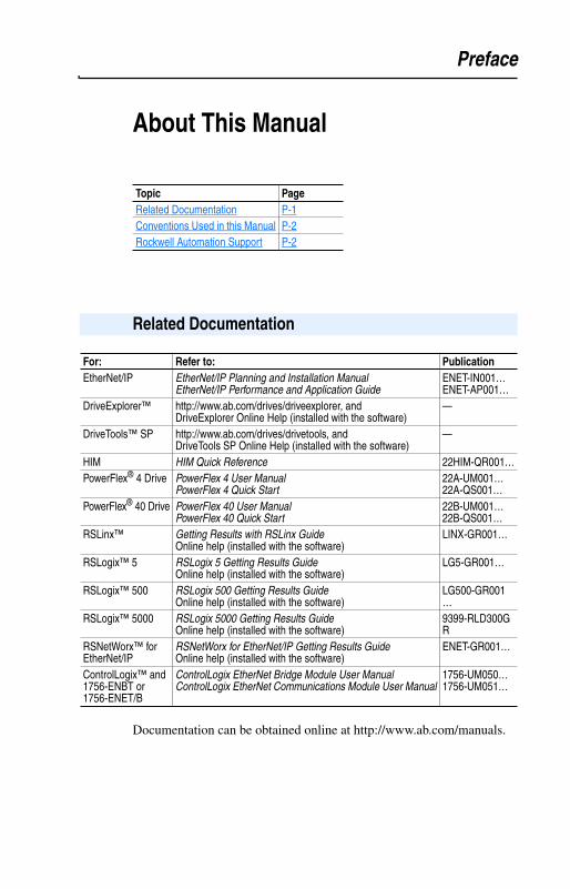
Documentation can be obtained online at http://www.ab.com/manuals.
Topic PageRelated Documentation P-1Conventions Used in this Manual P-2Rockwell Automation Support P-2
Related Documentation
For: Refer to: PublicationEtherNet/IP EtherNet/IP Planning and Installation Manual
EtherNet/IP Performance and Application GuideENET-IN001…ENET-AP001…
DriveExplorer™ http://www.ab.com/drives/driveexplorer, and DriveExplorer Online Help (installed with the software)
—
DriveTools™ SP http://www.ab.com/drives/drivetools, and DriveTools SP Online Help (installed with the software)
—
HIM HIM Quick Reference 22HIM-QR001…PowerFlex® 4 Drive PowerFlex 4 User Manual
PowerFlex 4 Quick Start22A-UM001…22A-QS001…
PowerFlex® 40 Drive PowerFlex 40 User ManualPowerFlex 40 Quick Start
22B-UM001…22B-QS001…
RSLinx™ Getting Results with RSLinx GuideOnline help (installed with the software)
LINX-GR001…
RSLogix™ 5 RSLogix 5 Getting Results GuideOnline help (installed with the software)
LG5-GR001…
RSLogix™ 500 RSLogix 500 Getting Results GuideOnline help (installed with the software)
LG500-GR001…
RSLogix™ 5000 RSLogix 5000 Getting Results GuideOnline help (installed with the software)
9399-RLD300GR
RSNetWorx™ for EtherNet/IP
RSNetWorx for EtherNet/IP Getting Results GuideOnline help (installed with the software)
ENET-GR001…
ControlLogix™ and 1756-ENBT or 1756-ENET/B
ControlLogix EtherNet Bridge Module User ManualControlLogix EtherNet Communications Module User Manual
1756-UM050…1756-UM051…

P-2 About This Manual
The following conventions are used throughout this manual:
• Parameter names are shown in the format Parameter xx - [*]. The xx represents the parameter number. The * represents the parameter name. For example Parameter 01 - [Mode].
• Menu commands are shown in bold type face and follow the format Menu > Command. For example, if you read “Select File > Open,” you should click the File menu and then click the Open command.
• The firmware release is displayed as FRN X.xxx. The “FRN” signifies Firmware Release Number. The “X” is the major release number. The “xxx” is the minor update number.
• RSNetWorx for EtherNet/IP (version 4.01), RSLinx (version 2.40), and RSLogix5000 (version 11) were used for the screen shots in this manual. Different versions of the software may differ in appearance and procedures.
• This manual provides information about the 22-COMM-E EtherNet/IP adapter and using it with PowerFlex 40 drives. The adapter can be used with other products that support an internal DSI adapter. Refer to the documentation for your product for specific information about how it works with the adapter.
Rockwell Automation, Inc. offers support services worldwide, with over 75 sales/support offices, over 500 authorized distributors, and over 250 authorized systems integrators located through the United States alone. In addition, Rockwell Automation, Inc. representatives are in every major country in the world.
Local Product Support
Contact your local Rockwell Automation, Inc. representative for:
• Sales and order support
• Product technical training
• Warranty support
• Support service agreements.
Conventions Used in this Manual
Rockwell Automation Support

About This Manual P-3
Technical Product Assistance
If you need to contact Rockwell Automation, Inc. for technical assistance, please review the information in Chapter 8, Troubleshootingfirst. If you still have problems, then call your local Rockwell Automation, Inc. representative.

P-4 About This Manual
Notes:

Chapter 1
Getting Started
The 22-COMM-E EtherNet/IP adapter is a communication option intended for installation into a PowerFlex 40 drive. It can also be used with other Allen-Bradley products that support an internal DSI adapter. The Multi-Drive feature (Chapter 7) also provides a means for PowerFlex 4 drives and other DSI Hosts to connect to EtherNet/IP.
Figure 1.1 Components of the Adapter
Topic Page Topic PageComponents 1-1 Safety Precautions 1-4Features 1-2 Quick Start 1-5Compatible Products 1-3 Modes of Operation 1-6Required Equipment 1-3
Components
Item Part Description
➊ Status Indicators
Four LEDs that indicate the status of the Ethernet connection, DSI, and the adapter. Refer to Chapter 8, Troubleshooting.
➋ DSI Connector A 20-pin, single-row shrouded male header. An Internal Interface cable is connected to this connector and a connector on the drive.
➌ Ethernet Connector
An RJ-45 connector for the Ethernet cable. The connector is CAT-5 compliant to ensure reliable data transfer on 100Base-TX Ethernet connections.
➍ Operating Mode Switch and Web Pages Switch
Selects Single or Multi-Drive mode of operation, and enables or disables the adapter web pages. Refer to Chapter 2, Setting Operating Mode and Web Pages Switches.
➊
➌
➋
➍
LEDs are on bottom side of adapter board
1-2 Getting Started
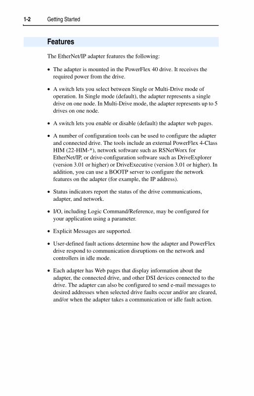
The EtherNet/IP adapter features the following:
• The adapter is mounted in the PowerFlex 40 drive. It receives the required power from the drive.
• A switch lets you select between Single or Multi-Drive mode of operation. In Single mode (default), the adapter represents a single drive on one node. In Multi-Drive mode, the adapter represents up to 5 drives on one node.
• A switch lets you enable or disable (default) the adapter web pages.
• A number of configuration tools can be used to configure the adapter and connected drive. The tools include an external PowerFlex 4-Class HIM (22-HIM-*), network software such as RSNetWorx for EtherNet/IP, or drive-configuration software such as DriveExplorer (version 3.01 or higher) or DriveExecutive (version 3.01 or higher). In addition, you can use a BOOTP server to configure the network features on the adapter (for example, the IP address).
• Status indicators report the status of the drive communications, adapter, and network.
• I/O, including Logic Command/Reference, may be configured for your application using a parameter.
• Explicit Messages are supported.
• User-defined fault actions determine how the adapter and PowerFlex drive respond to communication disruptions on the network and controllers in idle mode.
• Each adapter has Web pages that display information about the adapter, the connected drive, and other DSI devices connected to the drive. The adapter can also be configured to send e-mail messages to desired addresses when selected drive faults occur and/or are cleared, and/or when the adapter takes a communication or idle fault action.
Features

Getting Started 1-3
The EtherNet/IP adapter is compatible with Allen-Bradley PowerFlex Component Class drives and other products that support an internal DSI adapter. At the time of publication, compatible products include:
• PowerFlex 40 drives
The Multi-Drive feature (Chapter 7) also provides a means for PowerFlex 4 drives and other DSI Hosts to connect to EtherNet/IP.
Equipment Shipped with the Adapter
When you unpack the adapter, verify that the package includes:
User-Supplied Equipment
To install and configure the EtherNet/IP adapter, you must supply:
Phillips is a registered trademark of the Phillips Screw Company.
Compatible Products
Required Equipment
❑ One EtherNet/IP adapter❑ A 15.24 cm (6 in.) Internal Interface Cable❑ This manual
❑ A small flathead or Phillips® screwdriver❑ Ethernet cable (refer to the EtherNet/IP Media Planning and
Installation Manual, Publication No. ENET-IN001…, for details)❑ Configuration tool, such as:
– PowerFlex 4-Class HIM (22-HIM-*)– DriveExplorer (version 3.01 or higher)– DriveExecutive (version 3.01 or higher)– RSNetWorx for EtherNet/IP– BOOTP Server (version 2.1 or higher) (network setup only)
❑ A PC connection to the EtherNet/IP network.❑ Controller configuration software
(Examples: RSLogix5, RSLogix500, or RSLogix 5000)

1-4 Getting Started
Please read the following safety precautions carefully.
Safety Precautions
!ATTENTION: Risk of injury or death exists. The PowerFlex drive may contain high voltages that can cause injury or death. Remove all power from the PowerFlex drive, and then verify power has been removed before installing or removing an EtherNet/IP adapter.
!ATTENTION: Risk of injury or equipment damage exists. Only personnel familiar with drive and power products and the associated machinery should plan or implement the installation, start-up, configuration, and subsequent maintenance of the product using an EtherNet/IP adapter. Failure to comply may result in injury and/or equipment damage.
!ATTENTION: Risk of equipment damage exists. The EtherNet/IP adapter contains ESD (Electrostatic Discharge) sensitive parts that can be damaged if you do not follow ESD control procedures. Static control precautions are required when handling the adapter. If you are unfamiliar with static control procedures, refer to Guarding Against Electrostatic Damage, Publication 8000-4.5.2.
!ATTENTION: Risk of injury or equipment damage exists. If the EtherNet/IP adapter is transmitting control I/O to the drive, the drive may fault when you reset the adapter. Determine how your drive will respond before resetting an adapter.
!ATTENTION: Risk of injury or equipment damage exists. Parameters18 - [Comm Flt Action] and 19 - [Idle Flt Action] let you determine the action of the adapter and connected PowerFlex drive if communications are disrupted. By default, these parameters fault the drive. You can set these parameters so that the drive continues to run. Precautions should be taken to ensure that the settings of these parameters do not create a risk of injury or equipment damage. When commissioning the drive, verify that your system responds correctly to various situations (for example, a disconnected cable or a faulted controller).
!ATTENTION: Hazard of injury or equipment damage exists. When a system is configured for the first time, there may be unintended or incorrect machine motion. Disconnect the motor from the machine or process during initial system testing.
!ATTENTION: Hazard of injury or equipment damage exists. The examples in this publication are intended solely for purposes of example. There are many variables and requirements with any application. Rockwell Automation, Inc. does not assume responsibility or liability (to include intellectual property liability) for actual use of the examples shown in this publication.

Getting Started 1-5
This section is provided to help experienced users quickly start using the EtherNet/IP adapter. If you are unsure how to complete a step, refer to the referenced chapter.
Quick Start
Step Refer to . . . 1 Review the safety precautions for the adapter. Throughout This
Manual2 Verify that the PowerFlex drive is properly installed. Drive User Manual3 Install the adapter.
Verify that the PowerFlex drive is not powered. Then, connect the adapter to the network using an Ethernet cable and to the drive using the Internal Interface cable. Use the captive screw to secure and ground the adapter to the drive.
Chapter 2,Installing the Adapter
4 Apply power to the adapter.The adapter receives power from the drive. Apply power to the drive. The status indicators should be green. If they flash red, there is a problem. Refer to Chapter 8, Troubleshooting.
Chapter 2,Installing the Adapter
5 Configure the adapter for your application.Set the following parameters for the adapter as required by your application:• IP address, subnet mask, and gateway address• Data rate• I/O configuration• Fault actions
Chapter 3,Configuring the Adapter
6 Create a ladder logic program.Use a programming tool such as RSLogix to create a ladder logic program that enables you to:• Control the adapter and connected drive using I/O.• Monitor or configure the drive using Explicit Messages.
Chapter 4,Configuring the Scanner or Bridge
Chapter 5,Using I/O Messaging
Chapter 6,Using Explicit Messaging

1-6 Getting Started
The adapter uses four status indicators to report its operating status. They can be viewed on the adapter or through the drive cover. See Figure 1.2.
Figure 1.2 Status Indicators (location on drive may vary)
Modes of Operation
Item Status Indicator
Status (1)
(1) If all status indicators are off, the adapter is not receiving power. Refer to Chapter 2,Installing the Adapter, for instructions on installing the adapter.
If any other conditions occur, refer to Chapter 8, Troubleshooting.
Description
➊ PORT Green Normal Operation. The adapter is properly connected and is communicating with the drive.
Flashing Green
Normal Operation. The adapter is in the process of establishing a connection to the drive. This status indicator will turn solid green or red.
➋ MOD Green Normal Operation. The adapter is operational and is transferring I/O data.
Flashing Green
Normal Operation. The adapter is operational but is not transferring I/O data.
➌ NET A Green Normal Operation. The adapter is properly connected and communicating on the network.
Flashing Green
Normal Operation. The adapter is properly connected but is not communicating with any devices on the network.
➍ NET B Flashing Green
Normal Operation. The adapter is properly connected and is transmitting data packets on the network.
Off Normal Operation. The adapter is not transmitting data packets.
➊➋➌➍
➌➍
➊➋
Bottom sideof adapter board

Chapter 2
Installing the Adapter
Chapter 2 provides instructions for installing the adapter in a PowerFlex 40 drive.
Before installing the EtherNet/IP adapter:
• Read the EtherNet/IP Performance and Application Guide,Publication ENET-AP001…, and the EtherNet/IP Media Planning and Installation Manual, Publication ENET-IN001….
• Verify that you have all required equipment. Refer to Chapter 1,Getting Started.
Important: To guard against device malfunction, use a grounding wrist strap when installing the EtherNet/IP adapter.
Before installing the adapter, you must set its Operating Mode Switch for Single or Multi-Drive operation. To use the adapter web pages, the Web Pages Switch must be set to its “Enable Web” position.
Important: New settings are recognized only when power is applied to the adapter, or the adapter is reset. If you change a setting, cycle power or reset the adapter.
Topic PagePreparing for an Installation 2-1Setting Operating Mode and Web Pages Switches 2-1Connecting the Adapter to the Network 2-3Connecting the Adapter to the Drive 2-4Applying Power 2-6Commissioning the Adapter 2-6
Preparing for an Installation
Setting Operating Mode and Web Pages Switches

2-2 Installing the Adapter
1. Set the Operating Mode Switch (SW1) for Single or Multi-Drive operation (see Figure 2.1 and setting descriptions below). For complete details on Multi-Drive mode operation, see Chapter 7,Using Multi-Drive Mode.
Figure 2.1 Setting Single/Multi-Drive Operation and Web Page Enable Switches
2. Set the Web Pages Switch (SW2) to enable or disable the adapter web pages (see Figure 2.1 and setting descriptions below). By default, the adapter web pages are disabled. For complete details on the adapter web pages, see Chapter 9, Viewing the Adapter’s Web Pages.
!ATTENTION: Risk of equipment damage exists. The EtherNet/IP adapter contains ESD (Electrostatic Discharge) sensitive parts that can be damaged if you do not follow ESD control procedures. Static control precautions are required when handling the adapter. If you are unfamiliar with static control procedures, refer to Guarding Against Electrostatic Damage, Publication 8000-4.5.2.
SW1 Setting DescriptionDown position(DN = Closed = 0)
Sets the adapter for Single drive mode (default setting) using a single drive connection.
Important: In this mode, connections to multiple drives must be removed since all powered and connected hosts will respond to any message sent by the adapter.
Up position(UP = Open = 1)
Sets the adapter for Multi-Drive operation mode using up to 5 different drives. DSI peripherals (22-HIM-*, 22-SCM-*, etc.) do not operate with the adapter in this mode.
SW2 Setting DescriptionDown position(DN = Closed = 0)
Disables the adapter web pages (default setting).
Up position(UP = Open = 1)
Enables the adapter web pages.
21
OPERATING MODE SWITCH
Single-Drive Operation
Position
Multi-Drive Operation
Position
Disable Web Position
Enable Web Position
WEB PAGES SWITCH

Installing the Adapter 2-3
1. Remove power from the drive.
2. Use static control precautions.
3. Remove the drive cover.
4. Connect an Ethernet cable to the EtherNet/IP network. See Figure2.2 for an example of wiring to an EtherNet/IP network.
Figure 2.2 Connecting the Ethernet Cable to the Network
5. Route the Ethernet cable through the bottom of the PowerFlex drive (Figure 2.3), and insert the cable’s plug into the mating adapter receptacle.
Connecting the Adapter to the Network
!ATTENTION: Risk of injury or death exists. The PowerFlex drive may contain high voltages that can cause injury or death. Remove power from the PowerFlex drive, and then verify power has been discharged before installing or removing an adapter.
Switch
ControlLogix with EtherNet/IP Bridge
PowerFlex 40 with 22-COMM-E Router
(optional)
EtherNet/IP
PowerFlex 40 with 22-COMM-E

2-4 Installing the Adapter
1. Remove power from the drive.
2. Use static control precautions.
3. Mount the adapter on the required special drive cover (ordered separately — see Figure 2.4 for part numbers).
• C Frame: Use the adapter screw to secure the adapter to the cover.• B Frame: Disregard the screw and snap the adapter in place.
Important: For C Frame drives, tighten the adapter’s lower left screw to ground the adapter (see Figure 2.4). For B Frame drives, install the special drive cover onto the drive using both cover fasteners to ground the adapter.
4. Connect the Internal Interface cable to the DSI port on the drive and then to the mating DSI connector on the adapter.
Figure 2.3 DSI Ports and Internal Interface Cables
Connecting the Adapter to the Drive
Item Description➊ DSI Connector
➋ 15.24 cm (6 in.) Internal Interface cable
➌ Ethernet cable
PowerFlex 40 Drive(C Frame shown
with cover removed) Back of Required Special Drive Cover (ordered separately):
Part Number 22B-CCB for B FramePart Number 22B-CCC for C Frame
➋
EtherNet/IP Adapter
➊
➌

Installing the Adapter 2-5
Figure 2.4 Mounting and Grounding the Adapter
PowerFlex 40 Drive(C Frame shown
with cover removed)
Adapter Mounted on Back of Required Special Drive Cover
(C Frame cover shown)
Part Number 22B-CCB for B FramePart Number 22B-CCC for C Frame
Ground for C Frame drives
NOTE: For B Frame drives, the lower left adapter screw does not ground the adapter. To ground the adapter, install the special drive cover onto the drive using both cover fasteners.

2-6 Installing the Adapter
1. Install the required special cover on the drive. The status indicators can be viewed on the front of the drive after power has been applied.
2. Apply power to the PowerFlex drive. The adapter receives its power from the connected drive. When you apply power to the product for the first time, the status indicators should be green or off after an initialization. If the status indicators go red, there is a problem. Refer to Chapter 8, Troubleshooting.
To commission the adapter, you must set a unique IP address. (Refer to the Glossary for details about IP addresses.) After installing the adapter and applying power, you can set the IP address by using a BOOTP server or by setting parameters.
By default, the adapter is configured so that you must set the IP address using a BOOTP server. To set the IP address using parameters, you must disable the BOOTP feature. Refer to Chapter 3, Configuring the Adapter, for details.
Important: New settings for some parameters (for example, Parameters 03 - [IP Addr Cfg 1] through 06 - [IP Addr Cfg 4]) are recognized only when power is applied to the adapter or it is reset. After you change parameter settings, cycle power or reset the adapter.
Applying Power
!ATTENTION: Risk of equipment damage, injury, or death exists. Unpredictable operation may occur if you fail to verify that parameter settings and switch settings are compatible with your application. Verify that settings are compatible with your application before applying power to the drive.
Commissioning the Adapter

Chapter 3
Configuring the Adapter
Chapter 3 provides instructions and information for setting the parameters in the adapter.
For a list of parameters, refer to Appendix B, Adapter Parameters. For definitions of terms in this chapter, refer to the Glossary.
The EtherNet/IP adapter stores parameters and other information in its own non-volatile memory. You must, therefore, access the adapter to view and edit its parameters. The following tools can be used to access the adapter parameters:
Topic Page Topic PageConfiguration Tools 3-1 Setting the I/O Configuration 3-7Using the PowerFlex 4-Class HIM 3-2 Setting a Fault Action 3-8Using BOOTP 3-3 Setting Web Features Access 3-10Setting the IP Address, Subnet Mask, and Gateway Address
3-5 Resetting the Adapter 3-11
Setting the Data Rate 3-7 Viewing the Adapter Configuration 3-12
Configuration Tools
Tool Refer to . . .PowerFlex 4-Class HIM (22-HIM-*)
page 3-2
BOOTP Server page 3-3DriveExplorer Software (version 3.01 or higher)
DriveExplorer Online help (installed with the software)
DriveExecutive Software (version 3.01 or higher)
DriveExecutive Online help (installed with the software)

3-2 Configuring the Adapter
The PowerFlex 4-Class HIM (Human Interface Module) can be used to access parameters in the adapter (see basic steps shown below). It is recommended that you read through the steps for your HIM before performing the sequence. For additional HIM information, refer to the HIM Quick Reference card.
Using the HIM
Using the PowerFlex 4-Class HIM
Step Key(s) Example Screens1. Power up the drive.
Then plug the HIM into the drive. The Parameters menu for the drive will be displayed.
2. Press Sel key once to display the Device Selectmenu.
3. Press Enter to display the DSIDevices menu. Press Down Arrow to scroll to 22-COMM-E.
4. Press Enter to select the EtherNet/IP adapter. The Parameters menu for the adapter will be displayed.
5. Press Enter to access the parameters. Edit the adapter parameters using the same techniques that you use to edit drive parameters.
Parameters
GroupsLinear ListChanged Params
DIAG PARAM DSEL MEM SEL
Sel Device Selected
DSI Devices
DIAG PARAM DSEL MEM SEL
and DSI Devices
PowerFlex 4022-COMM-E
Parameters
Linear ListChanged Params
DIAG PARAM DSEL MEM SEL
Mode RO
Parameter: # 001
Single Drive 0
VALUE LIMITS SEL
Configuring the Adapter 3-3
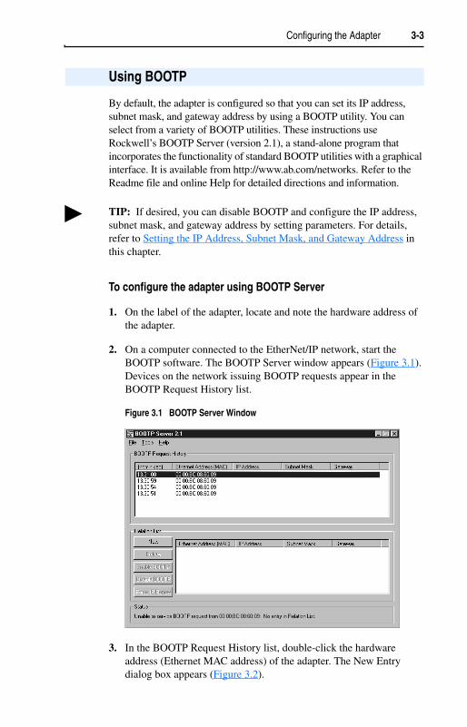
By default, the adapter is configured so that you can set its IP address, subnet mask, and gateway address by using a BOOTP utility. You can select from a variety of BOOTP utilities. These instructions use Rockwell’s BOOTP Server (version 2.1), a stand-alone program that incorporates the functionality of standard BOOTP utilities with a graphical interface. It is available from http://www.ab.com/networks. Refer to the Readme file and online Help for detailed directions and information.
To configure the adapter using BOOTP Server
1. On the label of the adapter, locate and note the hardware address of the adapter.
2. On a computer connected to the EtherNet/IP network, start the BOOTP software. The BOOTP Server window appears (Figure 3.1).Devices on the network issuing BOOTP requests appear in the BOOTP Request History list.
Figure 3.1 BOOTP Server Window
3. In the BOOTP Request History list, double-click the hardware address (Ethernet MAC address) of the adapter. The New Entry dialog box appears (Figure 3.2).
Using BOOTP
TIP: If desired, you can disable BOOTP and configure the IP address, subnet mask, and gateway address by setting parameters. For details, refer to Setting the IP Address, Subnet Mask, and Gateway Address in this chapter.

3-4 Configuring the Adapter
Figure 3.2 New Entry Dialog Box
4. Edit the following:
5. Click OK to apply the settings. The adapter appears in the Relation List with the new settings (Figure 3.3).
Figure 3.3 BOOTP Server Window with an Adapter in the Relation List
6. To assign this configuration to the adapter permanently, click Disable BOOTP. When power is cycled on the adapter, it will use the configuration you assigned it and not issue new BOOTP requests.
7. To save the Relation List, select File > Save.
Box (1)
(1) For definitions, refer to the Glossary.
TypeIP Address A unique IP address for the adapterSubnet Mask The subnet mask for the adapter’s networkGateway The IP address of the gateway device on the adapter’s network
TIP: To enable BOOTP for an adapter that has had BOOTP disabled, first select the adapter in the Relation List, then click Enable BOOTP, and finally reset the adapter.

Configuring the Adapter 3-5
By default, the adapter is configured so that you set its IP address, subnet mask, and gateway address using a BOOTP server. If you want to set these functions using the adapter’s parameters instead, you must first disable BOOTP and then set the appropriate parameters in the adapter.
To disable the BOOTP feature
1. Set the value of Parameter 02 - [BOOTP] to Disabled.
Figure 3.4 Example BOOTP Screen on PowerFlex 4-Class HIM (22-HIM-*)
2. Reset the adapter. See Resetting the Adapter section in this chapter.
After disabling the BOOTP feature, you can then configure the IP address, subnet mask, and gateway using the adapter’s parameters.
To set an IP address using parameters
1. Verify that Parameter 02 - [BOOTP] is set to Disabled. This parameter must be set to Disabled in order to configure the IP address using parameters.
2. Set the value of Parameters 03 - [IP Addr Cfg 1] through 06 - [IP Addr Cfg 4] to a unique IP address.
Figure 3.5 Example IP Address Screen on PowerFlex 4-Class HIM (22-HIM-*)
Setting the IP Address, Subnet Mask, and Gateway Address
Value Setting0 Disabled1 Enabled (Default)
BOOTP
Parameter: # 002
0
VALUE LIMITS SEL
Default = 0.0.0.0 255 . 255 . 255 . 255
[IP Addr Cfg 1]
[IP Addr Cfg 2]
[IP Addr Cfg 3]
[IP Addr Cfg 4]
IP Addr Cfg 1
Parameter: # 003
0
VALUE LIMITS SEL

3-6 Configuring the Adapter
3. Reset the adapter. See Resetting the Adapter section in this chapter.
The Net A status indicator will be solid green or flashing green if the IP address is correctly configured.
To set a subnet mask using parameters
1. Verify that Parameter 02 - [BOOTP] is set to Disabled. This parameter must be set to Disabled in order to configure the subnet mask using parameters.
2. Set the value of Parameters 07 - [Subnet Cfg 1] through 10 - [Subnet Cfg 4] to the desired value for the subnet mask.
Figure 3.6 Example Subnet Mask Screen on PowerFlex 4-Class HIM (22-HIM-*)
3. Reset the adapter. See Resetting the Adapter section in this chapter.
To set a gateway address for the adapter using parameters
1. Verify that Parameter 02 - [BOOTP] is set to Disabled. This parameter must be set to Disabled in order to configure the gateway address using parameters.
2. Set the value of Parameters 11 - [Gateway Cfg 1] through 14 - [Gateway Cfg 4] to the IP address of the gateway device.
Figure 3.7 Example Gateway Screen on PowerFlex 4-Class HIM (22-HIM-*)
3. Reset the adapter. See Resetting the Adapter section in this chapter.
Default = 0.0.0.0 255 . 255 . 255 . 255
[Subnet Cfg 1]
[Subnet Cfg 2]
[Subnet Cfg 3]
[Subnet Cfg 4]
Subnet Cfg 1
Parameter: # 007
0
VALUE LIMITS SEL
Default = 0.0.0.0 255 . 255 . 255 . 255
[Gateway Cfg 1]
[Gateway Cfg 2]
[Gateway Cfg 3]
[Gateway Cfg 4]
Gateway Cfg 1
Parameter: # 011
0
VALUE LIMITS SEL

Configuring the Adapter 3-7
By default, the adapter is set to autodetect, so it automatically detects the data rate and duplex setting used on the network. If you need to set a specific data rate and duplex setting, the value of Parameter 15 - [EN Rate Cfg] determines the Ethernet data rate and duplex setting that the adapter will use to communicate. For definitions of data rate and duplex, refer to the Glossary.
1. Set the value of Parameter 15 - [EN Rate Cfg] to the data rate at which your network is operating.
Figure 3.8 Ethernet Data Rate Screen on PowerFlex 4-Class HIM (22-HIM-*)
2. Reset the adapter. See Resetting the Adapter section in this chapter.
The I/O configuration determines the number of drives that will be represented on the network as one node by the adapter. If the Mode Switch is set to the Single mode (default) position, only one drive is represented by the adapter and Parameter 22 - [DSI I/O Cfg] has no effect. If the Operating Mode Switch is set to the Multi-Drive position, up to five drives can be represented as one node by the adapter.
1. Set the value in Parameter 22 - [DSI I/O Cfg].
Figure 3.9 I/O Configuration Screen on Powerflex 4-Class HIM (22-HIM-*)
Setting the Data Rate
Value Data Rate0 Autodetect (default)1 10M bits/sec Full2 10M bits/sec Half3 100M bits/sec Full4 100M bits/sec Half
EN Rate Cfg
Parameter: # 015
0
VALUE LIMITS SEL
Setting the I/O Configuration
Value DescriptionMode Switch PositionSingle Multi-Drive
0 Drive 0 (Default) ✓ ✓
1 Drives 0-1 ✓
2 Drives 0-2 ✓
3 Drives 0-3 ✓
4 Drives 0-4 ✓
DSI I/O Cfg
Parameter: # 022
Drive 0 0
VALUE LIMITS SEL

3-8 Configuring the Adapter
Drive 0 is the PowerFlex 40 with the 22-COMM-E adapter installed. Drive 1 through 4 are PowerFlex 4 and/or 40 drives that multi-drop to the RJ45 (RS-485) port on Drive 0. Refer to Chapter 7, UsingMulti-Drive Mode for more information.
2. If a drive is enabled, configure the parameters in the drive to accept the Logic Command and Reference from the adapter. For example, set Parameters 36 - [Start Source] and 38 - [Speed Reference] in a PowerFlex 40 drive to “Comm Port.”
3. Reset the adapter. See Resetting the Adapter section in this chapter.
By default, when communications are disrupted (for example, a cable is disconnected) or the scanner is idle, the drive responds by faulting if it is using I/O from the network. You can configure a different response to communication disruptions using Parameter 18 - [Comm Flt Action]and a different response to an idle scanner using Parameter 19 - [Idle Flt Action].
Setting a Fault Action
!ATTENTION: Risk of injury or equipment damage exists. Parameters 18 - [Comm Flt Action] and 19 - [Idle Flt Action] let you determine the action of the adapter and connected drive if communications are disrupted or the scanner is idle. By default, these parameters fault the drive. You can set these parameters so that the drive continues to run. Precautions should be taken to ensure that the settings of these parameters do not create a risk of injury or equipment damage. When commissioning the drive, verify that your system responds correctly to various situations (for example, a disconnected cable or faulted controller).

Configuring the Adapter 3-9
To change the fault action
• Set the values of Parameters 18 - [Comm Flt Action] and 19 - [Idle Flt Action] to the desired responses:
Figure 3.10 Fault Action Screens on PowerFlex 4-Class HIM (22-HIM-*)
Changes to these parameters take effect immediately. A reset is not required.
If Multi-Drive mode is used, the same fault action is used by the adapter for all of the drives it controls (Drive 0 - Drive 4).
To set the fault configuration parameters
If you set Parameter 18 - [Comm Flt Action] or 19 - [Idle Flt Action] to the “Send Flt Cfg,” the values in the following parameters are sent to the drive after a communications fault and/or idle fault occurs. You must set these parameters to values required by your application.
Changes to these parameters take effect immediately. A reset is not required.
Value Action Description0 Fault The drive is faulted and stopped. (Default)1 Stop The drive is stopped, but not faulted.2 Zero Data The drive is sent 0 for output data after a communications
disruption. This does not command a stop.3 Hold Last The drive continues in its present state after a communications
disruption.4 Send Flt Cfg The drive is sent the data that you set in the fault configuration
parameters (Parameters 20 - [Flt Cfg Logic] and 21 - [Flt Cfg Ref]).
Parameter Name Description20 Flt Cfg Logic A 16-bit value sent to the drive for Logic Command. 21 Flt Cfg Ref A 16-bit value (0 – 65535) sent to the drive as a Reference.
Comm Flt Action
Parameter: # 018
Fault 0
VALUE LIMITS SEL
Idle Flt Action
Parameter: # 019
Fault 0
VALUE LIMITS SEL

3-10 Configuring the Adapter
By accessing the IP address set for the adapter using a web browser, you can view the adapter’s web pages for information about the adapter, the PowerFlex drive to which it is connected, and other DSI devices connected to the drive such as HIMs, serial adapters or other daisy-chained drives (when adapter is in Multi-Drive mode). Additionally, the adapter can be configured to automatically send e-mail messages to desired addresses when selected drive faults occur and/or are cleared, and/or when the adapter takes a communication or idle fault action. For more details on the adapter’s web pages, refer to Chapter 9, Viewing the Adapter’s Web Pages.
By default, the adapter web pages are disabled.
To enable the adapter web pages
• Refer to Figure 2.1 and set the Web Pages Switch (SW2) to the “Enable Web” (up) position.
Important: For a change to the switch setting to take effect, the adapter must be reset (see Resetting the Adapter section in this chapter).
Bit 0 of Parameter 30 - [Web Features] is used to protect the configured settings for e-mail notification. By default, settings are not protected. To protect an e-mail configuration, set the value of E-mail Cfg Bit 0 to “0” (Disabled). You can unprotect the configuration by changing Bit 0 back to “1” (Enabled). E-mail notification will always remain active regardless of whether or not its settings are protected — unless e-mail notification was never configured. For more information about configuring adapter e-mail notification or stopping e-mail messages, refer to Chapter 9, Configure E-mail Notification Web Page.
Figure 3.11 Web Features Screen on Powerflex 4-Class HIM (22-HIM-*)
Bit 0 is the right-most bit. In Figure 3.11 it is highlighted and equals “1.”
Changes to this parameter take effect immediately. A reset is not required.
Setting Web Features Access
Bit Description0 E-mail Cfg (Default = 1 = Enabled)1 Proc Dsp Cfg (Default = 1 = Enabled)2 - 7 Not Used
Access Control
Parameter: # 030
x x x x x x 1 1
VALUE LIMITS SEL

Configuring the Adapter 3-11
Bit 1 of Parameter 30 - [Web Features] protects the configuration of parameters (names and values) shown in the “Process status” fields on both the Home page (Single Mode only) and Process Display pop-up window. By default, this configuration is not protected. To protect the configuration, set the value of Proc Dsp Cfg Bit 1 to “0” (Disabled). You can unprotected the configuration by changing Bit 1 back to “1” (Enabled). For more information about configuring the parameters for display, refer to the Configure Process Display Web Page section in Chapter 9.
Changes to switch settings and some adapter parameters require that you reset the adapter before the new settings take effect. You can reset the adapter by cycling power to the drive or by using the following parameter:
• Set Parameter 17 - [Reset Module] to Reset Module.
Figure 3.12 Reset Screen on PowerFlex 4-Class HIM (22-HIM-*)
When you enter 1 = Reset Module, the adapter will be immediately reset. When you enter 2 = Set Defaults, the adapter will set all adapter parameters to their factory-default settings. After performing a Set Defaults, enter 1 = Reset Module so that the new values take effect. The value of this parameter will be restored to 0 = Ready after the adapter is reset.
Resetting the Adapter
!ATTENTION: Risk of injury or equipment damage exists. If the adapter is transmitting control I/O to the drive, the drive may fault when you reset the adapter. Determine how your drive will respond before resetting a connected adapter.
Value Description0 Ready (Default)1 Reset Module2 Set Defaults
Reset Module
Parameter: # 017
Ready 0
VALUE LIMITS SEL

3-12 Configuring the Adapter
The following parameters provide information about how the adapter is configured. You can view these parameters at any time.
Viewing the Adapter Configuration
Number Name Description01 Mode The mode in which the adapter is set:
Values0 = Single drive operation2 = Multi-Drive operation
16 EN Rate Act The data rate used by the adapter:Values1 = 10M bits/sec full2 = 10M bits/sec half3 = 100M bits/sec full4 = 100M bits/sec half
23 DSI I/O Act Indicates the Drives that are active in the Multi-Drive mode:Bit Definitions0 = Drive 0 Active1 = Drive 1 Active2 = Drive 2 Active3 = Drive 3 Active4 = Drive 4 Active
29 Web Enable Indicates the setting of the Web Pages Switch (SW2) on the adapter when the adapter was last reset:
Values0 = Disabled1 = Enabled

Chapter 4
Configuring the Scanner or Bridge
Chapter 4 provides instructions on how to configure a ControlLogix bridge to communicate with the adapter and connected PowerFlex drive.
After the adapter is configured, the connected drive and adapter will be a single node on the network. This chapter provides the steps that are needed to configure a simple network like the network in Figure 4.1. In our example, we will configure a 1756-ENBT bridge to communicate with a drive using Logic Command/Status and Reference/Feedback over the network.
Figure 4.1 Example EtherNet/IP Network
Topic Page Topic PageExample Network 4-1 Adding the Adapter and Drive to the
I/O Configuration4-4
Adding a Bridge or Scanner to the I/O Configuration
4-2 Saving the Configuration 4-7
Example Network
PWR
STS
PORT
MOD
NET A
NET B
IP Address 131.200.130.176ControlLogix Controller with 1756-ENBT Bridge
Computer with Ethernet Connection
IP Address 131.200.130.178PowerFlex 40 Drive with EtherNet/IP Adapter
Switch
4-2 Configuring the Scanner or Bridge
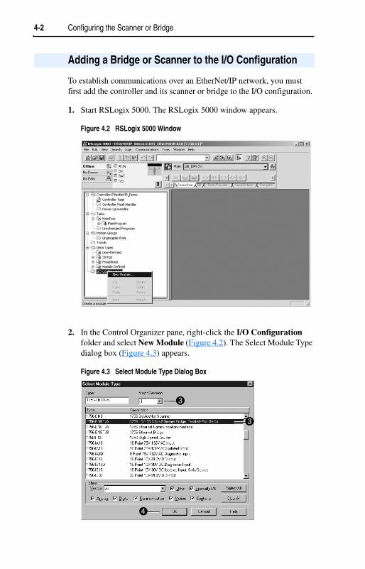
To establish communications over an EtherNet/IP network, you must first add the controller and its scanner or bridge to the I/O configuration.
1. Start RSLogix 5000. The RSLogix 5000 window appears.
Figure 4.2 RSLogix 5000 Window
2. In the Control Organizer pane, right-click the I/O Configurationfolder and select New Module (Figure 4.2). The Select Module Type dialog box (Figure 4.3) appears.
Figure 4.3 Select Module Type Dialog Box
Adding a Bridge or Scanner to the I/O Configuration
➌
➌
➍

Configuring the Scanner or Bridge 4-3
3. In the list, select the EtherNet/IP scanner or bridge used by your controller and then select the major revision of its firmware in the Major Revision box. In this example (Figure 4.3), we use a 1756-ENBT EtherNet/IP Bridge (Series A), so the 1756-ENBT/A option is selected.
4. Click OK. The Module Properties dialog box (Figure 4.4) appears.
Figure 4.4 Module Properties Dialog Box - Page 1
5. Edit the following:
6. Click Finish>>. The scanner or bridge is now configured for the EtherNet/IP network. It appears in the I/O Configuration folder. In our example, a 1756-ENBT bridge appears under the I/O Configuration folder (Figure 4.5).
Figure 4.5 RSLogix 5000: I/O Configuration Folder
Box TypeName A name to identify the scanner or bridge.Slot The slot of the EtherNet/IP scanner or bridge in the rack.Revision The minor revision of the firmware in the scanner. (You
already set the major revision in the Select Module Type dialog box, Figure 4.3 on page 4-2.)
IP Address The IP address of the EtherNet/IP scanner or bridge.Electronic Keying Compatible Module. This setting for Electronic Keying
ensures the physical module is consistent with the software configuration before the controller and scanner or bridge make a connection. Therefore, ensure that you have set the correct revision in this dialog box. Refer to the online Help if the controller and scanner have problems making a connection and you want to change this setting.

4-4 Configuring the Scanner or Bridge
To transmit data between the scanner or bridge and the adapter, you must add the 22-COMM-E adapter as a child device of the scanner or bridge.
1. In the Control Organizer pane, right-click on the scanner or bridge and select New Module (Figure 4.6). In our example, we right-click on the 1756-ENBT/A bridge.
Figure 4.6 Right-Clicking on the Scanner
The Select Module Type dialog box (Figure 4.7) appears.
Figure 4.7 Select Module Type Dialog Box
2. Select ETHERNET-MODULE to configure a 22-COMM-E (Figure 4.7), and then click OK.
Adding the Adapter and Drive to the I/O Configuration

Configuring the Scanner or Bridge 4-5
The Module Properties dialog box (Figure 4.8) appears.
Figure 4.8 Module Properties Dialog Box - Page 1
3. Edit the following information about the adapter:
4. Under Connection Parameters, edit the following:
Type the number of bytes that are required for your I/O in the Input Size and Output Size boxes. The size will depend on the I/O that you enabled in the adapter. This information can be found in Parameter 22 - [DSI I/O Cfg] in the adapter. Table 4.A shows common configuration Input/Output sizes.
In our example, we typed 4 in the Input Size and Output Size boxes because the Operating Mode Switch on the adapter is set to “Single” (default) and Parameter 22 - [DSI I/O Cfg] is set to “Drive 0” (only one drive being connected). Logic Command/Reference uses 2
Box TypeName A name to identify the adapter and drive.Comm. Format Data - INT.
This setting formats the data in 16-bit words.IP Address The IP address of the adapter.
Box Assembly Instance SizeInput 1 (This value is
required.)The value will vary based on your application (setting of Parameter 22 - [DSI I/O Cfg]). It will contain 2 additional words for ENBT overhead. Refer to Table 4.A on page 4-6.
Output 2 (This value is required.)
The value will vary based on your application (setting of Parameter 22 - [DSI I/O Cfg]).Refer to Table 4.A on page 4-6.
Configuration 6 (This value is required.)
0 (This value is required.)

4-6 Configuring the Scanner or Bridge
words and Logic Status/Feedback uses 2 words. The additional 2 words for the inputs are for ENBT overhead.
Table 4.A Input/Output Size Configurations
5. Click Next > to display the next page.
Figure 4.9 Module Properties Dialog Box - Page 2
6. In the Requested Packet Interval (RPI) box, set the value to 5.0 milliseconds or greater. This value determines the maximum interval that a controller should use to move data to or from the adapter. To conserve bandwidth, use higher values for communicating with low priority devices.
7. Click Finish>>. The new node (“PF40_Demo” in this example) now appears under the scanner or bridge (“1756-ENBT” in this example) in the I/O Configuration folder. If you double-click the Data Types folder and then double-click on the Module-Defined folder, you will see that module-defined data types and tags have been automatically created. After you save and download the configuration, these tags allow you to access the Input and Output data of the adapter via the controller’s ladder logic.
Input Size
Output Size
Logic Command/Status
Reference/Feedback
Parameter 22 - [DSI I/O Cfg]
Parameter 1 - [Mode]
4 2 ✔ ✔ Drive 0 Single6 4 ✔ ✔ Drives 0-1
Multi-Drive8 6 ✔ ✔ Drives 0-210 8 ✔ ✔ Drives 0-312 10 ✔ ✔ Drives 0-4
TIP: For instructions on configuring the I/O for the adapter (Parameter 22 - [DSI I/O Cfg]), see Chapter 3,Configuring the Adapter.

Configuring the Scanner or Bridge 4-7
Figure 4.10 RSLogix 5000 - I/O Configuration Folder
After adding the scanner or bridge and the adapter to the I/O configuration, you must download the configuration to the controller. You should also save the configuration to a file on your computer.
1. Select Communications > Download. The Download dialog box (Figure 4.11) appears.
Figure 4.11 Download Dialog Box
2. Click Download to download the configuration to the controller. When the download is completed successfully, RSLogix enters online mode and the I/O OK box in the upper-left part of the screen is green.
3. Select File > Save. If this is the first time that you saved the project, the Save As dialog box appears. Navigate to a folder, type a file name, and click Save to save the configuration to a file on your computer.
Saving the Configuration
TIP: If a message box reports that RSLogix is unable to go online, select Communications > Who Active to try to find your controller in the Who Active dialog box. If it does not appear, you need to add or configure the EtherNet/IP driver in RSLinx. Refer to the RSLinx online help.

4-8 Configuring the Scanner or Bridge
Notes:

Chapter 5
Using I/O Messaging
Chapter 5 provides information and examples that explain how to use a ControlLogix controller to send I/O Messaging to control, configure, and monitor a PowerFlex 40 drive.
Important: At the time of publication, only ControlLogix controllers can make an EtherNet/IP network I/O connection as described in this chapter; PLC-5’s and SLC’s cannot. However, these controllers can perform control using explicit messaging to the CIP Register object and PCCC N41 and N42 files.
On EtherNet/IP, I/O messaging is used to transfer the data which controls the PowerFlex drive and sets its Reference.
The EtherNet/IP adapter provides many options for configuring and using I/O, including configuring the size of I/O by selecting the number of attached drives (Single or Multi-Drive mode).
Chapter 3, Configuring the Adapter, and Chapter 4, Configuring the Scanner or Bridge, discuss how to configure the adapter and scanner or bridge on the network for these options. The Glossary defines the different options. This chapter discusses how to use I/O after you have configured the adapter and scanner or bridge.
Topic Page Topic PageAbout I/O Messaging 5-1 Using Reference/Feedback 5-3Understanding the I/O Image 5-2 Example Ladder Logic Program 5-3Using Logic Command/Status 5-2
!ATTENTION: Risk of injury or equipment damage exists. The examples in this publication are intended solely for purposes of example. There are many variables and requirements with any application. Rockwell Automation, Inc. does not assume responsibility or liability (to include intellectual property liability) for actual use of the examples shown in this publication.
About I/O Messaging

5-2 Using I/O Messaging
The terms input and output are defined from the scanner’s point of view. Therefore, Output I/O is data that is produced by the scanner and consumed by the EtherNet/IP adapter. Input I/O is status data that is produced by the adapter and consumed as input by the scanner. The I/O image table will vary based on the:
• Configuration of the Operating Mode Switch (SW1) on the adapter and (Parameter 22 - [DSI I/O Cfg]). The image table always uses consecutive words starting at word 0.
Figure 5.1 illustrates an example of a Single drive I/O image (16-bit words).
Figure 5.1 Single Drive Example of I/O Image
Single mode is the typical configuration, where one node consists of a PowerFlex 40 drive with a 22-COMM-E adapter.
For Multi-Drive mode, where one node can consist of up to 5 drives, refer to Chapter 7, Using Multi-Drive Mode.
When enabled, the Logic Command/Status word is always word 0 in the I/O image. The Logic Command is a 16-bit word of control produced by the scanner and consumed by the adapter. The Logic Status is a 16-bit word of status produced by the adapter and consumed by the scanner.
This manual contains the bit definitions for compatible products available at the time of publication in Appendix D, Logic Command/Status Words. For other products, refer to their documentation.
Understanding the I/O Image
Controller Scanner Adapter Word and I/O
PowerFlex 40 Drive
EtherNet/IP DSI
Output Image (Write)
Input Image (Read)
Message Handler
Message Buffer
0 Logic Status1 Feedback
Logic StatusFeedback
Message Handler
0 Logic Command1 Reference
Logic CommandReference
Using Logic Command/Status

Using I/O Messaging 5-3
When enabled, Reference/Feedback begins at word 1 in the I/O image. The Reference (16 bits) is produced by the controller and consumed by the adapter. The Feedback (16 bits) is produced by the adapter and consumed by the controller.
The example ladder logic program works with a ControlLogix controller and a PowerFlex 40 drive.
Function of the Example Program
This example program enables you to:
• Obtain status information from the drive.
• Use the Logic Command to control the drive (for example, start, stop).
• Send a Reference to the drive and receive Feedback from the drive.
Adapter Setting for the Example Program
• Adapter IP address 10. 91. 97. 74 is set using parameters.
• The adapter is configured for Single mode (Operating Mode Switch is set to “Single”).
RSLogix 5000 Configuration
Controller Tags
When you add the adapter and drive to the I/O configuration (see Chapter 4), RSLogix 5000 automatically creates controller tags for them. In this example program, the following controller tags are used.
Using Reference/Feedback
Size Valid Values (1)
(1) The Reference for a PowerFlex 4 or 40 is set in Hz. and not in engineering units like other PowerFlex drives. For example, “300” equates to 30.0 Hz (the decimal point is always implied).
In I/O Image Example16-bit 0.0 to 240.0 Hz (PowerFlex 4) or
0.0 to 400.0 Hz (PowerFlex 40)Word 1 Figure 5.1
Example Ladder Logic Program

5-4 Using I/O Messaging
Figure 5.2 Controller Tags for Example ControlLogix Ladder Logic Program
You can expand the Output and Input tags to reveal the output and input configuration. The Output tag for this example program requires two 16-bit words of data. The Input tag for this example requires four 16-bit words of data. See Figure 5.3.
Figure 5.3 Input/Output Image for Example ControlLogix Ladder Logic Program
Program Tags
In addition to the Controller tags that are automatically created, you need to create the following Program tags for this example program.
Figure 5.4 Program Tags for Example ControlLogix Ladder Logic Program

Using I/O Messaging 5-5
Logic Command/Status Words
This example uses the Logic Command word and Logic Status word for PowerFlex 40 drives. Refer to Appendix D, Logic Command/Status Words to view these. The definition of the bits in these words may vary if you are using a different DSI product. Refer to the documentation for your product.
Example ControlLogix Ladder Logic Program
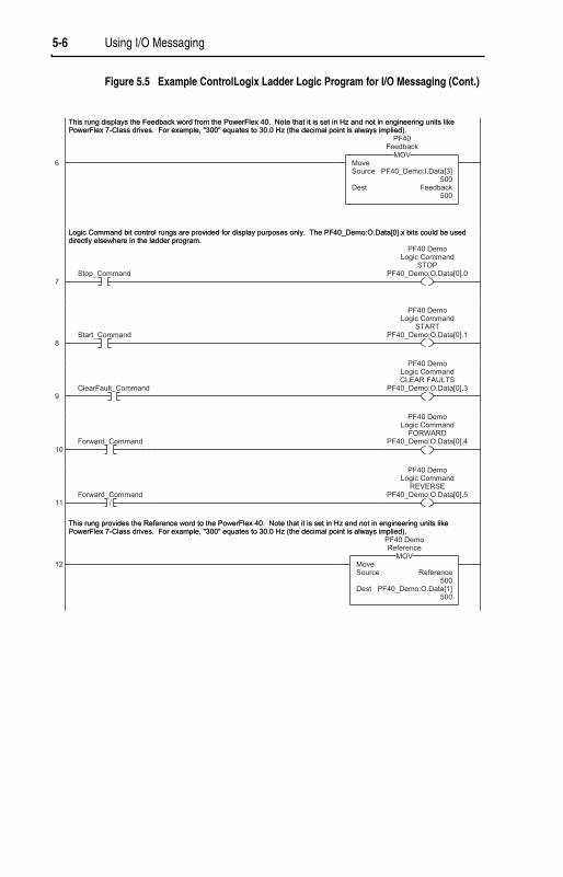
Figure 5.5 Example ControlLogix Ladder Logic Program for I/O Messaging
5-6 Using I/O Messaging
Figure 5.5 Example ControlLogix Ladder Logic Program for I/O Messaging (Cont.)

Chapter 6
Using Explicit Messaging
Chapter 6 provides information and examples that explain how to use Explicit Messaging to configure and monitor the EtherNet/IP adapter installed and connected to the PowerFlex 40 drive.
Refer to Chapter 5 for information about the I/O image, using Logic Command/Status and Reference/Feedback.
Explicit Messaging is used to transfer data that does not require continuous updates. With Explicit Messaging, you can configure and monitor a slave device’s parameters on the EtherNet/IP network.
Topic Page Topic PageAbout Explicit Messaging 6-1 About the Example Explicit Messages 6-5Formatting Explicit Messages 6-2 Example Get Attribute Single Message 6-6Performing Explicit Messages 6-4 Example Set Attribute Single Message 6-8
!ATTENTION: Risk of injury or equipment damage exists. The examples in this publication are intended solely for purposes of example. There are many variables and requirements with any application. Rockwell Automation, Inc. does not assume responsibility or liability (to include intellectual property liability) for actual use of the examples shown in this publication.
!ATTENTION: Risk of equipment damage exists. If Explicit Messages are programmed to write parameter data to Non-Volatile Storage (NVS) frequently, the NVS will quickly exceed its life cycle and cause the drive to malfunction. Do not create a program that frequently uses Explicit Messages to write parameter data to NVS.
About Explicit Messaging

6-2 Using Explicit Messaging
Explicit Messages for the ControlLogix Controller
ControlLogix scanners and bridges accommodate both downloading Explicit Message Requests and uploading Explicit Message Responses. The scanner or bridge module can accommodate one request or response for each transaction block. Each transaction block must be formatted as shown in Figure 6.1.
Figure 6.1 ControlLogix Message Format in RSLogix 5000
Refer to page 6-3 for a description of the data that is required in each box (1 – 11).
Formatting Explicit Messages
➋
➌ ➍➎ ➏
➐➑➒
➓
➊
11
TIP: To display the Message Configuration dialog box in RSLogix 5000, add a message instruction (MSG), create a new tag for the message (properties: Base tag type, MESSAGE data type, controller scope), and click the blue box inside the message.

Using Explicit Messaging 6-3
ControlLogix Message Requests and Responses
Box Description
➊ Message TypeThe message type must be CIP Generic.
➋ Service TypeThe service type indicates the service (for example, Get Attribute Single or Set Attribute Single) that you want to perform. Available services depend on the class and instance that you are using. Refer to Appendix C, EtherNet/IP Objects.
➌ Service CodeThe service code is the code for the requested EtherNet/IP service. This value changes based on the Service Type that has been selected. In most cases, this is a read-only box. If you select “Custom” in the Service Type box, then you need to specify a service code in this box (for example, 4B for a Get Attributes Scattered service or 4C for a Set Attributes Scattered service).
➍ ClassThe class is an EtherNet/IP class. Refer to Appendix C, EtherNet/IP Objects, for available classes.
➎ InstanceThe instance is an instance (or object) of an EtherNet/IP class. Refer to Appendix C, EtherNet/IP Objects, for available instances for each class.
➏ AttributeThe attribute is a class or instance attribute. Refer to Appendix C, EtherNet/IPObjects, for available attributes for each class or instance.
➐ Source ElementThis box contains the name of the tag for any service data to be sent from the scanner or bridge to the adapter and drive.
➑ Source LengthThis box contains the number of bytes of service data to be sent in the message.
➒ DestinationThis box contains the name of the tag that will receive service response data from the adapter and drive.
➓ PathThe path is the route that the message will follow.
Tip: Click Browse to find the path or type in the name of an adapter that you previously mapped.NameThe name for the message.
11

6-4 Using Explicit Messaging
There are five basic events in the Explicit Messaging process. The details of each step will vary depending on the controller. Refer to the documentation for your controller.
Figure 6.2 Explicit Message Process
Event
1. You format the required data and set up the ladder logic program to send an Explicit Message request to the scanner or bridge module (download).
2. The scanner or bridge module transmits the Explicit Message Request to the slave device over the Ethernet network.
3. The slave device transmits the Explicit Message Response back to the scanner. The data is stored in the scanner buffer.
4. The controller retrieves the Explicit Message Response from the scanner’s buffer (upload).
5. The Explicit Message is complete.
Performing Explicit Messages
➍
➎
➊
➋
➌
Set up and send ExplicitMessage Request
Complete Explicit Message
Retreive Explicit Message Respnse

Using Explicit Messaging 6-5
These examples show how to format and execute the following types of Explicit Messages using a ControlLogix controller:
• Get Attribute Single• Set Attribute Single
Message Formats
When formatting an example message, refer to Formatting Explicit Messages in this chapter for an explanation of the content of each box.
Also, to format and execute these example messages, you need the Controller tags displayed in Figure 6.3.
Figure 6.3 Controller Tags for Explicit Messages
Ladder Logic Rungs
The ladder logic rungs for the examples in this chapter can be appended after rung 12 in the ladder logic program (Figure 5.5) in Chapter 5,Using I/O Messaging.
Source and Destination Data
The example values for the source and destination data that appear in this chapter may vary in your application.
About the Example Explicit Messages

6-6 Using Explicit Messaging
A Get Attribute Single message reads a single attribute value. In this example, we read the value of a parameter in a PowerFlex 40 drive.
Example Message Format
Figure 6.4 Message Format for a Get Attribute Single Message
The following table identifies key settings for the message format:
Example Get Attribute Single Message
Configuration Value Description Refer to . . .Service Type (1)
Service Code (1)
ClassInstanceAttributeDestination
(1) The default setting for Service Type is “Custom,” which enables you to enter a Service Code that is not available from the Service Type pulldown menu. When you select a Service Type other than “Custom” from the pulldown menu, an appropriate Hex. value is automatically assigned to the Service Code box which grays out (unavailable).
Get Attribute Singlee (Hex.)f (Hex.)39 (Dec.)1 (Hex.)ParameterReadValue
Read parameter dataGet_Attribute_SingleDSI Parameter ObjectParameter 39 - [Accel Time 1]Parameter ValueController tag for response data
C-27C-12C-24C-24C-25—

Using Explicit Messaging 6-7
Example Ladder Logic Rung
Figure 6.5 Example Get Attribute Single Message
Example Destination Data
In this example, the Get Attribute Single message reads Parameter 39 - [Accel Time 1] in the PowerFlex 40 drive and returns its value to the destination tag named ParameterReadValue.
Figure 6.6 Example Destination Data from a Get Attribute Single Message
The acceleration time is 10.0 seconds.

6-8 Using Explicit Messaging
A Set Attribute Single message writes a value for a single attribute. In this example, we write the value of a parameter in a PowerFlex 40 drive.
Example Message Format
Figure 6.7 Message Format for a Set Attribute Single Message
The following table identifies key settings for the data format:
Example Set Attribute Single Message
Configuration Value Description Refer to . . .Service Type (1)
Service Code (1)
ClassInstanceAttributeSource ElementSource Length
(1) The default setting for Service Type is “Custom,” which enables you to enter a Service Code that is not available from the Service Type pulldown menu. When you select a Service Type other than “Custom” from the pulldown menu, an appropriate Hex. value is automatically assigned to the Service Code box which grays out (unavailable).
Set Attribute Single10 (Hex.)f (Hex.)39 (Dec.)1 (Hex.)ParameterWriteValue2 bytes
Write parameter dataSet_Attribute_SingleDSI Parameter ObjectParameter 39 - [Accel Time 1]Parameter ValueController tag for write dataOne 16-bit word of data is sent
C-27C-12C-24C-24C-25——

Using Explicit Messaging 6-9
Example Ladder Logic Rung
Figure 6.8 Example Set Attribute Single Message
Example Source Data
In this example, the Set Attribute Single message writes 100, the value in the source tag named ParameterWriteValue, to Parameter 39 - [Accel Time 1] in the PowerFlex 40 drive.
Figure 6.9 Example Source Data from a Set Attribute Single Message
10.0 seconds is written to the parameter.

6-10 Using Explicit Messaging
Notes:

Chapter 7
Using Multi-Drive Mode
Chapter 7 provides information and a ControlLogix ladder example to explain how to use Multi-Drive mode.
Single mode is a typical network installation, where a single EtherNet/IP node consists of a single drive with a 22-COMM-E adapter (Figure 7.1).
Figure 7.1 Single Mode Example for Network
Multi-Drive mode is an alternative to the typical network installation, where a single EtherNet/IP node can consist of one to five drives (Figure 7.2). The first drive must be a PowerFlex 40 with a 22-COMM-E adapter. The remaining drives can be PowerFlex 4 or PowerFlex 40 drives that are daisy-chained over RS-485 with the first drive.
Topic Page Topic PageSingle Mode vs. Multi-Drive Mode 7-1 Multi-Drive Ladder Logic Program
Example7-6
System Wiring 7-3 ControlLogix Example 7-7Understanding the I/O Image 7-4 Multi-Drive Mode Explicit Messaging 7-20Configuring the RS-485 Network 7-5 Additional Information 7-22
!ATTENTION: Risk of injury or equipment damage exists. The examples in this publication are intended solely for purposes of example. There are many variables and requirements with any application. Rockwell Automation, Inc. does not assume responsibility or liability (to include intellectual property liability) for actual use of the examples shown in this publication.
Single Mode vs. Multi-Drive Mode
PowerFlex 40 with 22-COMM-E
PowerFlex 40 with 22-COMM-E
PowerFlex 40 with 22-COMM-E
EtherNet/IP1 drive per node

7-2 Using Multi-Drive Mode
Figure 7.2 Multi-Drive Mode Example for Network
Benefits of Multi-Drive mode include:
• Lower hardware costs. Only one 22-COMM-E adapter is needed for up to five drives. PowerFlex 4’s can also be used for the daisy-chained drives instead of PowerFlex 40’s.
• Reduces the network node count. For example, in Single mode 30 drives would consume 30 nodes. In Multi-Drive mode, 30 drives can be connected in 6 nodes.
• Provides a means to put PowerFlex 4’s on EtherNet/IP (PowerFlex 4’s do not have an internal communications adapter slot).
• Controller can control, monitor, and read/write parameters for all five drives.
The trade-offs of Multi-Drive mode include:
• If the PowerFlex 40 with the 22-COMM-E adapter is powered down, then communications with the daisy-chained drives is disrupted and the drives will take the appropriate communications loss action set in each drive.
• Communications throughput to the daisy-chained drives will be slower than if each drive was a separate node on EtherNet/IP (Single mode). This is because the 22-COMM-E adapter must take the EtherNet/IP data for the other drives and sequentially send the respective data to each drive over RS-485. The approximate additional throughput time for Logic Command/Reference to be transmitted and received by each drive is:
Drive Additional Throughput Time versus Single Mode
PowerFlex 40 with 22-COMM-E 0 msPowerFlex 40 with 22-COMM-E plus 1 drive +24 msPowerFlex 40 with 22-COMM-E plus 2 drives +48 msPowerFlex 40 with 22-COMM-E plus 3 drives +72 msPowerFlex 40 with 22-COMM-E plus 4 drives +96 ms
EtherNet/IPup to 5 drives per node
PowerFlex 40
22-COMM-E
Up to 4 PowerFlex 4's or 40's
AK-U0-RJ45-TB2PConnector with
Terminating ResistorAK-U0-RJ45-TB2P
Connector with Terminating Resistor
AK-U0-RJ45-TB2PRS-485

Using Multi-Drive Mode 7-3
• Since the RS-485 ports are used for daisy-chaining the drives, there is no connection for a peripheral device such as a HIM. The AK-U0-RJ45-SC1 DSI Splitter cable cannot be used to add a second connection for a peripheral device.
To daisy-chain the drives off the PowerFlex 40 with the 22-COMM-E adapter (Drive 0), the AK-U0-RJ45-TB2P terminal block connector (Figure 7.3) can be used for easy installation.
Figure 7.3 AK-U0-RJ45-TB2P Terminal Block Connector
The wiring diagram for using AK-U0-RJ45-TB2P terminal block connectors is shown in Figure 7.4.
Figure 7.4 AK-U0-RJ45-TB2P Connector Wiring Diagram
The AK-U0-RJ45-TB2P comes with (5) terminal block connectors and (2) terminating resistors.
System Wiring
To PowerFlex 40
with 22-COMM-D
To Drive #2
To Drive #3
To Drive #4
To Drive #5
120 Ω ¼ Watt
Resistor
120 Ω ¼ Watt
Resistor

7-4 Using Multi-Drive Mode
The terms input and output are defined from the scanner’s point of view. Therefore, Output I/O is data that is output from the scanner and consumed by the EtherNet/IP adapter. Input I/O is status data that is produced by the adapter and consumed as input by the scanner. The I/O image table will vary based on the:
• Configuration of the Operating Mode Switch (SW1) on the adapter and Parameter 22 - [DSI I/O Cfg]. The image table always uses consecutive words starting at word 0.
Figure 7.5 illustrates the Multi-Drive I/O image with 16-bit words.
Figure 7.5 Multi-Drive Example of I/O Image
Note: If a daisy-chained drive is disconnected from the RS-485 (DSI) network or powered down, the Logic Status and Feedback words for the affected drive will be set to 0.
Understanding the I/O Image
Controller Scanner Adapter Word and I/O
EtherNet/IP DSI
Output Image (Write)
Input Image (Read)
Message Handler
Message Buffer
0 Logic Command1 Reference
2 Logic Command3 Reference
4 Logic Command5 Reference
6 Logic Command7 Reference
8 Logic Command9 Reference
0 Logic Status1 Feedback
2 Logic Status3 Feedback
4 Logic Status5 Feedback
6 Logic Status7 Feedback
8 Logic Status9 Feedback
PowerFlex Drive 2
PowerFlex Drive 0
PowerFlex Drive 1
PowerFlex Drive 3
PowerFlex Drive 4
PowerFlex Drive 0
PowerFlex Drive 1
PowerFlex Drive 2
PowerFlex Drive 3
PowerFlex Drive 4

Using Multi-Drive Mode 7-5
The following parameters must be set in the daisy-chained drives:
Note that the RS-485 network is fixed at 19.2K baud, 8 data bits, no parity, and 1 stop bit.
Important: Parameters A105 - [Comm Loss Action] and A106 - [Comm Loss Time] in the daisy-chained drives are still used in Multi-Drive mode. If the RS-485 cable is disconnected or broken, the disconnected drive(s) will take the corresponding Comm Loss Action(s). On the EtherNet/IP side, Parameters 18 - [Comm Flt Action] and 19 - [Idle Flt Action] in the 22-COMM-E determine the action taken for ALL of the drives on the Multi-Drive node.
The following Multi-Drive parameters must be set in the 22-COMM-E:
After setting the 22-COMM-E parameters, set the Operating Mode Switch (SW1) from Single drive operation to Multi-Drive operation (set to ON position), and reset the adapter or cycle power. Refer to Chapter 2,Setting Operating Mode and Web Pages Switches.
Important: 22-COMM-E parameters can be set using a DSI peripheral (HIM, DriveExplorer with 22-SCM-232, etc.) ONLY when the Operating Mode Switch is in the Single mode position (SW1 = OFF).
Configuring the RS-485 Network
Parameter ValueP36 - [Start Source] 5 (Comm Port)P38 - [Speed Reference] 5 (Comm Port)A103 - [Comm Data Rate] 4 (“19.2K”)A104 - [Comm Node Addr] 1-247 (must be unique)A107 - [Comm Format] 0 (“RTU 8-N-1”)
Parameter Value22 - [DSI I/O Cfg] 0 = Drive 0 connected
1 = Drives 0-1 connected2 = Drives 0-2 connected3 = Drives 0-3 connected4 = Drives 0-4 connected
24 - [Drv 0 Addr] = Parameter A104 - [Comm Node Address] in Drive 025 - [Drv 1 Addr] = Parameter A104 - [Comm Node Address] in Drive 126 - [Drv 2 Addr] = Parameter A104 - [Comm Node Address] in Drive 227 - [Drv 3 Addr] = Parameter A104 - [Comm Node Address] in Drive 328 - [Drv 4 Addr] = Parameter A104 - [Comm Node Address] in Drive 4

7-6 Using Multi-Drive Mode
The example ladder logic program demonstrates using Multi-Drive mode with five drives. See Figure 7.2 for a system layout diagram.
Function of the Example Program
The example program provided is for the ControlLogix, but other controllers can also be used. This example program enables you to:
• View status information from the drives such as Ready, Fault, At Speed, and Feedback.
• Control the drives using various Logic Command bits (Stop, Start, etc.) and Reference.
• Perform a single parameter read and write for each drive. The example uses drive Parameter 39 - [Accel Time] for both so you can see (read) the change after a write is performed.
Adapter Settings for the Example Program
• The Operating Mode Switch (SW1) on the adapter is set to the Multi-Drive operation position. See Chapter 2, Setting Operating Mode and Web Pages Switches.
• The following adapter parameters are set:
Multi-Drive Ladder Logic Program Example
Parameter Value Description22 - [DSI I/O Cfg] 4 “Drives 0-4” — 5 drives on 1 node24 - [Drv 0 Addr] (1)
(1) The settings for these parameters must match the Parameter A104 - [Comm Node Addr] settings in the respective drives.
1 Modbus address of Drive 025 - [Drv 1 Addr] (1) 2 Modbus address of Drive 126 - [Drv 2 Addr] (1) 3 Modbus address of Drive 227 - [Drv 3 Addr] (1) 4 Modbus address of Drive 328 - [Drv 4 Addr] (1) 5 Modbus address of Drive 4

Using Multi-Drive Mode 7-7
Drive Settings for the Example Program
The following common Tags are used:
The following Tags are used for Drive 0:
ParameterValue
Drive 0 Drive 1 Drive 2 Drive 3 Drive 4P36 - [Start Source] 5 5 5 5 5P38 - [Speed Reference] 5 5 5 5 5A103 - [Comm Data Rate] 4 4 4 4 4A104 - [Comm Node Addr](1)
(1) The settings for these parameters must match the respective parameter settings in the adapter (Parameter 17 - [Drv 0 Addr] through Parameter 21 - [Drv 4 Addr]).
1 2 3 4 5A105 - [Comm Loss Action] 0 0 0 0 0A106 - [Comm Loss Time] 5 5 5 5 5A107 - [Comm Format] 0 0 0 0 0
ControlLogix Example
Tag Name Type DescriptionMultiDrive_Demo : I AB: 1756_E...
1756-ENBT I/OMultiDrive_Demo : O AB: 1756_E...MultiDrive_Demo : C AB: 1756_E...Drive Input Image INT [10] Input Image TableDrive Output Image INT [10] Output Image Table
Tag Name Type DescriptionDrive 0 Command Stop BOOL Logic Command bit 0 (STOP)Drive 0 Command Start BOOL Logic Command bit 1 (START)Drive 0 Command Jog BOOL Logic Command bit 2 (JOG)Drive 0 Command Clear Faults BOOL Logic Command bit 3 (CLEAR FAULTS)Drive 0 Command Forward BOOL Logic Command bit 4 (FORWARD)Drive 0 Reference INT Speed ReferenceDrive 0 Status Ready BOOL Logic Status bit 0 (READY)Drive 0 Status Active BOOL Logic Status bit 1 (ACTIVE)Drive 0 Status Forward BOOL Logic Status bit 3 (FORWARD)Drive 0 Status Faulted BOOL Logic Status bit 7 (FAULT)Drive 0 Status At Reference BOOL Logic Status bit 8 (AT SPEED)Drive 0 Feedback INT Speed FeedbackPerform Parameter Read 0 BOOL Initiates the parameter readParameter RD Value 0 INT Read value of the parameterParameter RD Message 0 MESSAGE Get_Attribute_Single (Read)

7-8 Using Multi-Drive Mode
The same type of Tags are also used for Drive 1 through Drive 4.
Main Routine
The Main Routine reads the network Input Image from the scanner, calls the various drive control subroutines, and writes the network Output Image to the scanner. See Figure 7.6.
Perform Parameter Write 0 BOOL Initiates the parameter valueParameter WR Value 0 INT Write value to the parameterParameter WR Message 0 MESSAGE Set_Attribute_Single (Write)
Tag Name Type Description

Using Multi-Drive Mode 7-9
Figure 7.6 Main Routine

7-10 Using Multi-Drive Mode
Drive 0 - Drive 4 Control Routines
The following Drive Control routines provide status information (Logic Status and Feedback), control (Logic Command and Reference), and parameter read/write for each of the respective drives:
Figure 7.6 Main Routine (Continued)
Control Routine Refer to . . .Drive 0 Figure 7.7Drive 1 Figure 7.8Drive 2 Figure 7.9Drive 3 Figure 7.10Drive 4 Figure 7.11

Using Multi-Drive Mode 7-11
Figure 7.7 Drive 0 Control Routine

7-12 Using Multi-Drive Mode
Figure 7.7 Drive 0 Control Routine (Continued)

Using Multi-Drive Mode 7-13
Figure 7.8 Drive 1 Control Routine
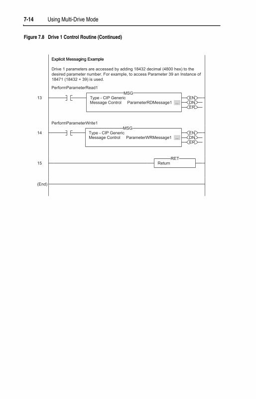
7-14 Using Multi-Drive Mode
Figure 7.8 Drive 1 Control Routine (Continued)

Using Multi-Drive Mode 7-15
Figure 7.9 Drive 2 Control Routine

7-16 Using Multi-Drive Mode
Figure 7.9 Drive 2 Control Routine (Continued)
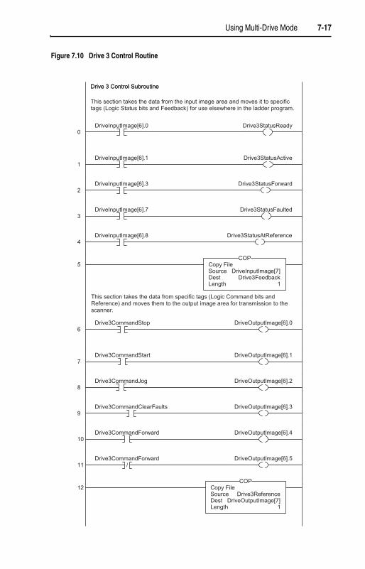
Using Multi-Drive Mode 7-17
Figure 7.10 Drive 3 Control Routine

7-18 Using Multi-Drive Mode
Figure 7.10 Drive 3 Control Routine (Continued)

Using Multi-Drive Mode 7-19
Figure 7.11 Drive 4 Control Routine
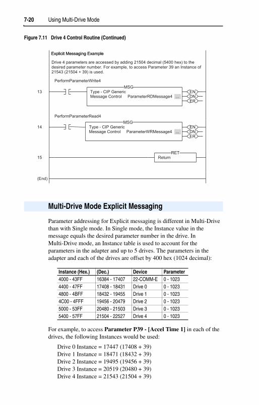
7-20 Using Multi-Drive Mode
Parameter addressing for Explicit messaging is different in Multi-Drive than with Single mode. In Single mode, the Instance value in the message equals the desired parameter number in the drive. In Multi-Drive mode, an Instance table is used to account for the parameters in the adapter and up to 5 drives. The parameters in the adapter and each of the drives are offset by 400 hex (1024 decimal):
For example, to access Parameter P39 - [Accel Time 1] in each of the drives, the following Instances would be used:
Drive 0 Instance = 17447 (17408 + 39)Drive 1 Instance = 18471 (18432 + 39)Drive 2 Instance = 19495 (19456 + 39)Drive 3 Instance = 20519 (20480 + 39)Drive 4 Instance = 21543 (21504 + 39)
Figure 7.11 Drive 4 Control Routine (Continued)
Multi-Drive Mode Explicit Messaging
Instance (Hex.) (Dec.) Device Parameter4000 - 43FF 16384 - 17407 22-COMM-E 0 - 10234400 - 47FF 17408 - 18431 Drive 0 0 - 10234800 - 4BFF 18432 - 19455 Drive 1 0 - 10234C00 - 4FFF 19456 - 20479 Drive 2 0 - 10235000 - 53FF 20480 - 21503 Drive 3 0 - 10235400 - 57FF 21504 - 22527 Drive 4 0 - 1023

Using Multi-Drive Mode 7-21
Drive 0 Explicit Message Example
The Explicit message examples in the ControlLogix example program perform a read (Get_Attribute_Single) and a write (Set_Attribute_Single) to Parameter 39 - [Accel Time 1]. The configuration for the read is shown in Figure 7.12 and the write is shown in Figure 7.13.
Figure 7.12 Parameter Read Message Configuration
Figure 7.13 Parameter Write Message Configuration

7-22 Using Multi-Drive Mode
The Class Code is “ f ” for the Parameter Object and the Instance Attribute is “1” to select retrieving the parameter value. See Appendix C,Parameter Object for more information. The Instance value is “17447” to access Parameter 39 - [Accel Time 1].
The Explicit messages for Drive 1 to Drive 4 are identical except for the Instance values:
Drive 1 Instance = 18471 (18432 + 39)Drive 2 Instance = 19495 (19456 + 39)Drive 3 Instance = 20519 (20480 + 39)Drive 4 Instance = 21543 (21504 + 39)
• When the PowerFlex 40 with the 22-COMM-E (Drive 0) is powered up, all configured daisy-chained drives must be present before an I/O connection is allowed on EtherNet/IP (i.e. before the drives can be controlled).
• If the PowerFlex 40 with the 22-COMM-E adapter (Drive 0) is powered down, communications with the four daisy-chained drives (Drive 1 to Drive 4) are disrupted and the drives will take their corresponding Comm Loss Actions.
• If any of the daisy-chained drives (Drive1 to Drive 4) are powered down, the respective Input Image (Logic Status and Feedback) sent to the scanner will be zeros, and the NET A and PORT LEDs on the 22-COMM-E adapter will flash red. Status information from the scanner will not indicate there is a fault at the node, and the I/O connection will not be dropped.
Additional Information

Chapter 8
Troubleshooting
Chapter 8 provides information for troubleshooting potential problems with the adapter.
The EtherNet/IP adapter has four status indicators. They can be viewed on the adapter or through the drive cover. See Figure 8.1.
Figure 8.1 Status Indicators (location on drive may vary)
Topic Page Topic PageLocating the Status Indicators 8-1 Adapter Diagnostic Items in
Single Drive Mode8-5
PORT Status Indicator 8-2 Adapter Diagnostic Items in Multi-Drive Mode
8-7
MOD Status Indicator 8-3 Viewing and Clearing Events 8-8Net A Status Indicator 8-4
Locating the Status Indicators
Item Status Indicator Description Page➊ PORT DSI Connection Status 8-2
➋ MOD Adapter Status 8-3
➌ NET A EtherNet/IP Connection Status 8-4
➍ NET B EtherNet/IP Transmit Status 8-5
➊➋➌➍
➌➍
➊➋
Bottom sideof adapter board

8-2 Troubleshooting
PORT Status Indicator
Status Cause Corrective ActionOff The adapter is not powered or
properly connected to the drive.
• Securely connect the adapter to the drive using the Internal Interface (ribbon) cable.
• Apply power to the drive.Flashing Red
In Single mode, the adapter is not receiving communication from the drive.
In Multi-Drive mode, the adapter is not receiving communication from a drive, or a drive is not an Allen-Bradley drive.
• Verify the setting for Parameter 22 - [DSI I/O Cfg].
• Verify that cables are securely connected and not damaged. Replace cables if necessary.
• Cycle power to the drive.
• Use Allen-Bradley PowerFlex 4/40 drives.Flashing Green
The adapter is establishing communications with the drive.
No action required. This status indicator will turn solid green or flashing red.
SolidGreen
The adapter is properly connected and is communicating with the drive.
No action required.
Orange In Single mode, the drive is not an Allen-Bradley drive.
Use an Allen-Bradley PowerFlex 40 drive.

Troubleshooting 8-3
MOD Status Indicator
Status Cause Corrective ActionOff The adapter is not powered or
properly connected to the drive.
• Securely connect the adapter to the drive using the Internal Interface (ribbon) cable.
• Apply power to the drive.Flashing Red
The adapter has failed the firmware test.
• Cycle power to the drive.
• If cycling power does not correct the problem, the adapter parameter settings may have been corrupted. Reset defaults and reconfigure the adapter.
• If resetting defaults does not correct the problem, flash the adapter with the latest firmware release.
SolidRed
The adapter has failed the hardware test.
• Cycle power to the drive.
• Replace the adapter.Flashing Green
The adapter is operational, but is not transferring I/O data.
• Place the scanner in RUN mode.
• Program the controller to recognize and transmit I/O to the adapter.
• Configure the adapter for the program in the controller.
SolidGreen
The adapter is operational and transferring I/O data.
No action required.

8-4 Troubleshooting
Net A Status Indicator
Status Cause Corrective ActionsOff The adapter and/or
network is not powered, the adapter is not properly connected to the network, or the adapter needs an IP address.
• Securely connect the adapter to the drive using the Internal Interface (ribbon) cable and to the network using an Ethernet cable.
• Correctly connect the Ethernet cable to the Ethernet connector.
• Set a unique IP address using a BOOTP server or by disabling BOOTP and using adapter parameters.
• Apply power to the drive and network.Flashing Red
An EtherNet/IP connection has timed out.
• Place the scanner in RUN mode.
• Check the amount of traffic on the network.SolidRed
The adapter failed the duplicate IP address detection test.
Configure the adapter to use a unique IP address and cycle power.
Flashing Green
The adapter is properly connected but is not communicating with any devices on the network.
• Place the controller in RUN mode.
• Program the controller to recognize and transmit I/O or make a messaging connection to the adapter.
• Configure the adapter for the program in the controller.
SolidGreen
The adapter is properly connected and communicating on the network.
No action required.
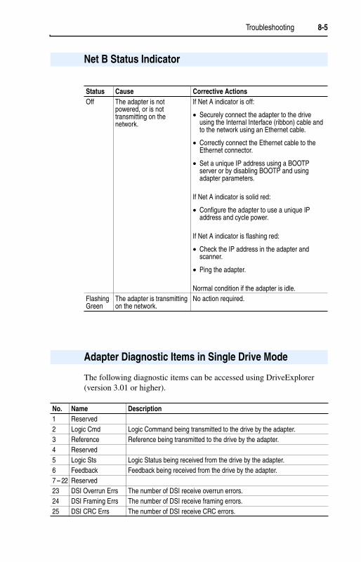
Troubleshooting 8-5
The following diagnostic items can be accessed using DriveExplorer (version 3.01 or higher).
Net B Status Indicator
Status Cause Corrective ActionsOff The adapter is not
powered, or is not transmitting on the network.
If Net A indicator is off:
• Securely connect the adapter to the drive using the Internal Interface (ribbon) cable and to the network using an Ethernet cable.
• Correctly connect the Ethernet cable to the Ethernet connector.
• Set a unique IP address using a BOOTP server or by disabling BOOTP and using adapter parameters.
If Net A indicator is solid red:
• Configure the adapter to use a unique IP address and cycle power.
If Net A indicator is flashing red:
• Check the IP address in the adapter and scanner.
• Ping the adapter.
Normal condition if the adapter is idle.Flashing Green
The adapter is transmitting on the network.
No action required.
Adapter Diagnostic Items in Single Drive Mode
No. Name Description1 Reserved2 Logic Cmd Logic Command being transmitted to the drive by the adapter.3 Reference Reference being transmitted to the drive by the adapter.4 Reserved5 Logic Sts Logic Status being received from the drive by the adapter.6 Feedback Feedback being received from the drive by the adapter.7 – 22 Reserved 23 DSI Overrun Errs The number of DSI receive overrun errors.24 DSI Framing Errs The number of DSI receive framing errors.25 DSI CRC Errs The number of DSI receive CRC errors.
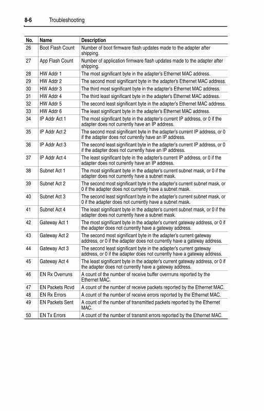
8-6 Troubleshooting
26 Boot Flash Count Number of boot firmware flash updates made to the adapter after shipping.
27 App Flash Count Number of application firmware flash updates made to the adapter after shipping.
28 HW Addr 1 The most significant byte in the adapter’s Ethernet MAC address.29 HW Addr 2 The second most significant byte in the adapter’s Ethernet MAC address.30 HW Addr 3 The third most significant byte in the adapter’s Ethernet MAC address.31 HW Addr 4 The third least significant byte in the adapter’s Ethernet MAC address.32 HW Addr 5 The second least significant byte in the adapter’s Ethernet MAC address.33 HW Addr 6 The least significant byte in the adapter’s Ethernet MAC address.34 IP Addr Act 1 The most significant byte in the adapter’s current IP address, or 0 if the
adapter does not currently have an IP address.35 IP Addr Act 2 The second most significant byte in the adapter’s current IP address, or 0
if the adapter does not currently have an IP address.36 IP Addr Act 3 The second least significant byte in the adapter’s current IP address, or 0
if the adapter does not currently have an IP address.37 IP Addr Act 4 The least significant byte in the adapter’s current IP address, or 0 if the
adapter does not currently have an IP address.38 Subnet Act 1 The most significant byte in the adapter’s current subnet mask, or 0 if the
adapter does not currently have a subnet mask.39 Subnet Act 2 The second most significant byte in the adapter’s current subnet mask, or
0 if the adapter does not currently have a subnet mask.40 Subnet Act 3 The second least significant byte in the adapter’s current subnet mask, or
0 if the adapter does not currently have a subnet mask.41 Subnet Act 4 The least significant byte in the adapter’s current subnet mask, or 0 if the
adapter does not currently have a subnet mask.42 Gateway Act 1 The most significant byte in the adapter’s current gateway address, or 0 if
the adapter does not currently have a gateway address.43 Gateway Act 2 The second most significant byte in the adapter’s current gateway
address, or 0 if the adapter does not currently have a gateway address.44 Gateway Act 3 The second least significant byte in the adapter’s current gateway
address, or 0 if the adapter does not currently have a gateway address.45 Gateway Act 4 The least significant byte in the adapter’s current gateway address, or 0 if
the adapter does not currently have a gateway address.46 EN Rx Overruns A count of the number of receive buffer overrruns reported by the
Ethernet MAC.47 EN Packets Rcvd A count of the number of receive packets reported by the Ethernet MAC.48 EN Rx Errors A count of the number of receive errors reported by the Ethernet MAC.49 EN Packets Sent A count of the number of transmitted packets reported by the Ethernet
MAC.50 EN Tx Errors A count of the number of transmit errors reported by the Ethernet MAC.
No. Name Description

Troubleshooting 8-7
The following diagnostic items can be accessed using DriveExplorer (version 3.01 or higher).
Adapter Diagnostic Items in Multi-Drive Mode
No. Name Description1 Reserved2 Drv 0 Logic Cmd Logic Command being transmitted to drive 0 by the adapter.3 Drv 0 Reference Reference being transmitted to drive 0 by the adapter.4 Reserved5 Drv 0 Logic Sts Logic Status being received from drive 0 by the adapter.6 Drv 0 Feedback Feedback being received from drive 0 by the adapter.7 Drv 1 Logic Cmd Logic Command being transmitted to drive 1 by the adapter.8 Drv 1 Reference Reference being transmitted to drive 1 by the adapter.9 Drv 1 Logic Sts Logic Status being received from drive 1 by the adapter.10 Drv 1 Feedback Feedback being received from drive 1 by the adapter.11 Drv 2 Logic Cmd Logic Command being transmitted to drive 2 by the adapter.12 Drv 2 Reference Reference being transmitted to drive 2 by the adapter.13 Drv 2 Logic Sts Logic Status being received from drive 2 by the adapter.14 Drv 2 Feedback Feedback being received from drive 2 by the adapter.15 Drv 3 Logic Cmd Logic Command being transmitted to drive 3 by the adapter.16 Drv 3 Reference Reference being transmitted to drive 3 by the adapter.17 Drv 3 Logic Sts Logic Status being received from drive 3 by the adapter.18 Drv 3 Feedback Feedback being received from drive 3 by the adapter.19 Drv 4 Logic Cmd Logic Command being transmitted to drive 4 by the adapter.20 Drv 4 Reference Reference being transmitted to drive 4 by the adapter.21 Drv 4 Logic Sts Logic Status being received from drive 4 by the adapter.22 Drv 4 Feedback Feedback being received from drive 4 by the adapter.23 DSI Overrun Errs The number of DSI receive overrun errors.24 DSI Framing Errs The number of DSI receive framing errors.25 DSI CRC Errs The number of DSI receive CRC errors.26 Boot Flash Count Number of boot firmware flash updates made to the adapter after
shipping.27 App Flash Count Number of application firmware flash updates made to the adapter after
shipping.28 HW Addr 1 The most significant byte in the adapter’s Ethernet MAC address.29 HW Addr 2 The second most significant byte in the adapter’s Ethernet MAC address.30 HW Addr 3 The third most significant byte in the adapter’s Ethernet MAC address.31 HW Addr 4 The third least significant byte in the adapter’s Ethernet MAC address.32 HW Addr 5 The second least significant byte in the adapter’s Ethernet MAC address.33 HW Addr 6 The least significant byte in the adapter’s Ethernet MAC address.34 IP Addr Act 1 The most significant byte in the adapter’s current IP address, or 0 if the
adapter does not currently have an IP address.35 IP Addr Act 2 The second most significant byte in the adapter’s current IP address, or 0
if the adapter does not currently have an IP address.36 IP Addr Act 3 The second least significant byte in the adapter’s current IP address, or 0
if the adapter does not currently have an IP address.

8-8 Troubleshooting
The adapter maintains an event queue that reports the history of its actions. You can view the event queue using DriveExplorer (3.01) software.
Figure 8.2 DriveExplorer Event View/Clear Screen
37 IP Addr Act 4 The least significant byte in the adapter’s current IP address, or 0 if the adapter does not currently have an IP address.
38 Subnet Act 1 The most significant byte in the adapter’s current subnet mask, or 0 if the adapter does not currently have a subnet mask.
39 Subnet Act 2 The second most significant byte in the adapter’s current subnet mask, or 0 if the adapter does not currently have a subnet mask.
40 Subnet Act 3 The second least significant byte in the adapter’s current subnet mask, or 0 if the adapter does not currently have a subnet mask.
41 Subnet Act 4 The least significant byte in the adapter’s current subnet mask, or 0 if the adapter does not currently have a subnet mask.
42 Gateway Act 1 The most significant byte in the adapter’s current gateway address, or 0 if the adapter does not currently have a gateway address.
43 Gateway Act 2 The second most significant byte in the adapter’s current gateway address, or 0 if the adapter does not currently have a gateway address.
44 Gateway Act 3 The second least significant byte in the adapter’s current gateway address, or 0 if the adapter does not currently have a gateway address.
45 Gateway Act 4 The least significant byte in the adapter’s current gateway address, or 0 if the adapter does not currently have a gateway address.
46 EN Rx Overruns A count of the number of receive buffer overrruns reported by the Ethernet MAC.
47 EN Packets Rcvd A count of the number of receive packets reported by the Ethernet MAC.48 EN Rx Errors A count of the number of receive errors reported by the Ethernet MAC.49 EN Packets Sent A count of the number of transmitted packets reported by the Ethernet
MAC.50 EN Tx Errors A count of the number of transmit errors reported by the Ethernet MAC.
No. Name Description
Viewing and Clearing Events

Troubleshooting 8-9
Events
Many events in the Event queue occur under normal operation. If you encounter unexpected communications problems, the events may help you or Allen-Bradley personnel troubleshoot the problem. The following events may appear in the event queue:
Code Event DescriptionAdapter Events
0 No Event Text displayed in an empty event queue entry.1 Normal Startup Power is applied to the adapter.2 Manual Reset The adapter was reset from the “Reset Module” parameter.3 Watchdog T/O Flt The software watchdog detected a failure and reset the
adapter.4 App Updated The application firmware has been flash updated.5 Boot Updated The boot firmware has been flash updated.6 EEPROM Sum Flt The EEPROM checksum/CRC in incorrect. The functionality
of the adapter will be limited. Default parameter values must be loaded to clear the condition.
7 – 9 ReservedDSI Events
10 Slave Detected The adapter detected that the slave has been connected.11 Slave Removed The adapter detected that the slave has been disconnected.12 Slave Logon The adapter has established communications with the slave.13 Slave Timeout The adapter has lost communications with the slave.14 Slave Brand Flt The slave brand is different than the adapter.15 Host 0 Logon The adapter has established communications with host 0.16 Host 1 Logon The adapter has established communications with host 1.17 Host 2 Logon The adapter has established communications with host 2.18 Host 3 Logon The adapter has established communications with host 3.19 Host 4 Logon The adapter has established communications with host 4.20 Host 0 Timeout The adapter has lost communications with host 0.21 Host 1 Timeout The adapter has lost communications with host 1.22 Host 2 Timeout The adapter has lost communications with host 2.23 Host 3 Timeout The adapter has lost communications with host 3.24 Host 4 Timeout The adapter has lost communications with host 4.25 Host 0 Brand Flt The host 0 brand is different than the adapter.26 Host 1 Brand Flt The host 1 brand is different than the adapter.27 Host 2 Brand Flt The host 2 brand is different than the adapter.28 Host 3 Brand Flt The host 3 brand is different than the adapter.29 Host 4 Brand Flt The host 4 brand is different than the adapter.30 – 39 Reserved
Network Events40 EN Link Up The network link is established.41 EN Link Down The network link is lost.42 Dup IP Addr The adapter detected that another device is using its
network address. In this case, the adapter will not participate in any network activity.

8-10 Troubleshooting
43 EN Open An I/O connection from the network to the adapter was opened.44 EN Close An I/O connection from the network to the adapter was closed.45 EN Timeout An I/O connection from the network to the adapter has timed
out.46 EN Comm Flt The adapter has performed the “Comm Flt” action specified
by the user.47 EN Idle Flt The adapter has performed the “Idle Flt” action specified by
the user.48 PCCC IO Open The adapter has begun receiving PCCC Control messages
(the PCCC Control Timeout was previously set to a non-zero value).
49 PCCC IO Close The device sending PCCC Control messages to the adapter has set the PCCC Control Timeout to a value of zero.
50 PCCC IO Time Flt The adapter has not received a PCCC Control message for longer than the PCCC Control Timeout.
51 EN Sent Reset The adapter received a reset from the network.52 Msg Ctrl Open The adapter has begun receiving Client-Server Control
messages (the Client-Server Control Timeout was previously set to a non-zero value).
53 Msg Ctrl Close The device sending Client-Server Control messages to the adapter has set the Client-Server Control Timeout to a value of zero.
54 Msg Ctrl Timeout The adapter has not received a Client-Server Control message for longer than the established timeout period.
55 – 59 ReservedAdapter-Specific Events
60 BOOTP Response The adapter received a response to its BOOTP request.61 E-mail Failed The adapter attempted to send an e-mail notice, but could
not deliver the message to the mail server.
Code Event Description

Chapter 9
Viewing the Adapter’s Web Pages
Chapter 9 provides instructions on how to monitor the adapter and connected PowerFlex drive using the adapter’s web interface.
Future enhancements may result in adapter web pages that look different than the examples shown in this chapter.
After configuring the adapter, you can view its web pages. These pages present information about the adapter, the drive to which it is connected, and other DSI devices connected to the drive such as a HIM or other daisy-chained drives (when adapter is operated in Multi-Drive mode).
The adapter can be configured to automatically send e-mail messages to desired addresses when selected drive faults occur and/or are cleared, and/or when the adapter takes a communication or idle fault action. For more details, see the Configure E-mail Notification Web Page section in this chapter.
Bits 0 and 1 of Parameter 30 - [Web Features] can be used to respectively protect the configured settings for e-mail notification and the Process Display web page. The process display settings determine the parameters whose values you want shown in the “Process status” field on the Home page and the Process Display pop-up window for the host. (When the adapter is operated in Multi-Drive mode, the Home Page does not show a “Process status” field for a host.) For details to protect settings, refer to Chapter 3, Setting Web Features Access.
Topic Page Topic PageAccessing the Adapter’s Web Home Page
9-1 Configure E-mail Notification Web Page
9-8
Process Display Pop-up Windows 9-6 Configure Process Display Web Page 9-10TCP/IP Configuration Web Page 9-7 DSI Device Information Pages 9-11
Accessing the Adapter’s Web Home Page
TIP: By default the adapter web pages are disabled. To enable the web pages, set the Web Pages Switch (SW2 in Figure 2.1) to its “Enable Web” position and then reset the adapter.

9-2 Viewing the Adapter’s Web Pages
To view the web pages of the adapter
1. On a computer with access to the EtherNet/IP network on which the adapter is installed, launch a web browser such as Microsoft™ Internet Explorer (version 5.0 or greater) or Netscape® Navigator®
(version 4.6 or greater).
The computer can access the adapter web pages if it is connected to the same network as the adapter, or if it is connected to a network with access to the adapter’s network via a gateway device (for example, a router).
2. In the Address box (Explorer) or Location box (Navigator), type the IP address of the adapter, and then press ENTER. The web Home Page for the adapter appears.
Important: Clicking the browser’s Refresh button always re-displays the Home Page even while viewing another adapter web page.
Figure 9.1 Adapter Web Home Page Example (Single Mode)

Viewing the Adapter’s Web Pages 9-3
Figure 9.2 Adapter Web Home Page Example (Multi-Drive mode)
Title Bar on Adapter Web Pages
The title bar appears on all adapter web pages, including its Home Page. It consists of three elements:
Navigation Menu on Adapter Web Pages
The navigation menu appears on the left side of all adapter web pages, including its Home Page. The navigation menu consists of links and link folders which can be expanded or minimized. There are some slight differences in the navigation menu when the adapter is operated in Single mode versus Multi-Drive mode. These differences are highlighted
Item Description
Allen-Bradley logo (at far left)
This logo is also a link. Click it to view the ab.com web Home Page.
Adapter Title (middle) Shows the adapter type and title.
Rockwell Automation logo (at far right)
This logo is also a link. Click it to view the Rockwell Automation web Home Page.

9-4 Viewing the Adapter’s Web Pages
in the following table, which shows all of the navigation menu’s links and link folders:
Link/Folder Description
Home link Click this link to view the adapter’s Home Page (Figure 9.1 or Figure 9.2).
Process Display link (only Single mode)
Process Display folder (only Multi-Drive mode)
Clck this link to view the Host’s Process Display pop-up window (Figure 9.3) showing dynamic process information (updates every 3 seconds).
Click this folder to expand and view the links for all connected hosts (Host 0 – X). Then click a respective host’s link to view its Process Display pop-up window (Figure 9.3) showing dynamic process information (updates every 3 seconds).
TCP/IP configuration link
Click this link to view the adapter’s TCP/IP Configuration web page showing information about the TCP/IP configuration, such as the adapter’s IP address and the number of packets being sent. Figure 9.4 shows an example TCP/IP Configuration web page.
Configure e-mail notification link
Click this link to view the adapter’s Configure E-mail Notification web page (Figure 9.5) for configuring the adapter to send automatic e-mail messages. See Figure 9.6 for an example e-mail message.
Configure process display link
Click this link to view the adapter’s Configure Process Display web page (Figure 9.7) for configuring the parameters whose values you want shown in the “Process status” field on the Home Page (static values) and the Process Display pop-up window for the host (dynamic values).
Browse DSI devices folder
Click this folder to expand and view the Port folders for all present DSI devices, including the drive, adapter, and other DSI devices connected to the drive such as a HIM or other daisy-chained drives (when the adapter is in Multi-Drive mode).
Port 0 – X folders(X = total connected hosts)
Click a respective Port folder to expand and view its device’s “Module information” link, “Module diagnostics” link, and “Fault queue” link, which take you to related information pages. See Figure 9.8, Figure 9.9, and Figure 9.10 for examples of these pages.
Online user manuals link
Click this link to view Allen-Bradley’s web page with documentation for drives and other devices.
Software tools Web site link
Click this link to view Allen-Bradley’s web page with information about software tools such as DriveExplorer and DriveExecutive.
Launch my DriveExplorer software link
Click this link to launch the DriveExplorer software already installed on your PC.
Launch my DriveExecutive software link
Click this link to launch the DriveExecutive software already installed on your PC.
E-mail technical support link
Click this link to view a new e-mail message window to send a message to Allen-Bradley’s Technical Support Team.

Viewing the Adapter’s Web Pages 9-5
Information on Adapter Home Page
The adapter Home Page displays the following information for the adapter and host:
Item DescriptionAdapter Information • Revision
• IP Address• Ethernet Address (MAC)• Serial Number• Status• I/O connection status
Host “X” Information Information for each connected host includes:
Adapter In Single Mode• Revision• Status• Commanded direction• Rotation drection• Process status
Adapter In Multi-Drive Mode• Revision• Status

9-6 Viewing the Adapter’s Web Pages
The Process Display pop-up window dynamically shows a host’s information. To view this window, click the “Process Display” link in the navigation menu.
Figure 9.3 Example of Process Display Pop-up Window for Host 0
Process Display Pop-up Windows
TIP: To view Process Display pop-up windows when the adapter is operated in Multi-Drive mode, expand the “Process Display” folder and click the respective Host “X” link.
Information DescriptionProduct text Description of host.Status Status of host.Commanded direction Commanded direction of host.Rotation direction Rotation direction of host.Process status Line 1 – desired parameter of host and its dynamic value. (1)
Line 2 – desired parameter of host and its dynamic value. (1)
Line 3 – desired parameter of host and its dynamic value. (1)
(1) The parameter whose value is shown on this line can be set by using the Configure Process Display web page. For details, see the Configure Process Display Web Pagesection in this chapter.

Viewing the Adapter’s Web Pages 9-7
The TCP/IP Configuration web page provides details about the adapter’s EtherNet/IP settings and network activities.
Figure 9.4 Example of TCP/IP Configuration Web Page
TCP/IP Configuration Web Page
Information DescriptionIP Address IP address of the adapter.Subnet Mask Subnet mask for the adapter’s network.Gateway Address Address for the gateway device on the adapter’s network.BOOTP Whether BOOTP is being used to configure the adapter’s
network information.Ethernet Address Hardware address for the adapter.Ethernet received packets Number of packets that the adapter has received.Ethernet receive errors Number of receive errors reported by the hardware.Ethernet receive overruns Number of receive buffer overruns reported by the
hardware.Ethernet transmitted packets Number of packets that the adapter has sent.Ethernet transmit errors Number of transmit errors reported by the hardware.

9-8 Viewing the Adapter’s Web Pages
The Configure E-mail Notification web page contains selections and data fields for configuring the adapter to automatically send e-mail messages to desired addresses when selected types of events occur. By default, this configuration is not protected. After configuration, the settings can be protected by setting the Parameter 30 - [Web Features]E-mail Cfg Bit 0 value to “0” (Disabled). To change a protected configuration, it must first be unprotected by setting the E-mail Cfg Bit 0 value back to “1” (Enabled). For more information, see Chapter 3,Setting Web Features Access.
Figure 9.5 Example of Configure E-mail Notification Web Page
To configure e-mail notification
1. Click the desired Host Faults check boxes you want to occur that will send e-mail notification:
– If you only want e-mail notification when specific faults occur, click this radio button and type the fault numbers in the box.
– If you only want e-mail notification when all faults except specific faults occur, click this radio button and type the fault numbers in the box.
Configure E-mail Notification Web Page

Viewing the Adapter’s Web Pages 9-9
2. Click the desired Adapter Faults check boxes you want to occur that will send e-mail notification.
3. Type the following information in their respective boxes:
4. Click Save changes.
Important: It is recommended that Parameter 30 - [Web Features] E-mail Cfg Bit 0 value be set to “0” (Disabled) after E-mail Notification has been configured. Otherwise the configuration can be changed anytime the web page is accessed with a browser.
An example of an e-mail message automatically sent by the adapter in response to selected events is shown below.
Figure 9.6 Example of E-mail Message Sent by Adapter
Information Description“IP address of …" Type in the address of the mail server that will be
used to deliver the e-mail messages.“E-mail addresses to notify …" Type in addresses to where you want e-mail
messages to be sent. Multiple addresses can be used, but they must be separated by commas (comma delimited).
“Subject of e-mail message …" Type in the desired subject text for the e-mail message.
TIP: To stop e-mail messages, do one of the following:
• Delete all e-mail addresses from the Configure E-mail Notification web page.
• Uncheck all of the “Send an e-mail message when …” boxes.
Disabling the adapter web pages by setting the Web Pages Switch (SW2 in Figure 2.1) to the “Disable Web” position will NOT stop the adapter from sending e-mail messages.

9-10 Viewing the Adapter’s Web Pages
The Configure Process Display web page enables you to set a host’s parameters whose values you want shown in the “Process status” fields on the Home Page and the Process Display pop-up window. (When the adapter is operated in Multi-Drive mode, the Home Page does not show a “Process status” field for a host.) By default, this configuration is not protected. After configuration, the settings can be protected by setting the Parameter 30 - [Web Features] Proc Dsp Cfg Bit 1 value to “0” (Disabled). To change a protected configuration, it must first be unprotected by setting the Proc Dsp Cfg Bit 1 value back to “1” (Enabled). For more information, see Chapter 3, Setting Web Features Access.
Figure 9.7 Example of Configure Process Display Web Page (Single Mode)
1. To set a host’s parameters whose values you want shown on Lines 1, 2, and 3 of the “Process status” fields in both the Home Page (only Single mode) and Process Display pop-up window (Figure 9.3), type the corresponding parameter number in each box.
Configure Process Display Web Page
Information DescriptionLine 1 – parameter # Number of the parameter whose value you want on Line 1.Line 2 – parameter # Number of the parameter whose value you want on Line 2.Line 3 – parameter # Number of the parameter whose value you want on Line 3.

Viewing the Adapter’s Web Pages 9-11
2. Click Save changes.
Important: It is recommended that Parameter 30 - [Web Features] Proc Dsp Cfg Bit 1 value be set to “0” (Disabled) after configuration. Otherwise the configuration can be changed anytime the web page is accessed with a browser.
DSI device information pages show a device’s module information, diagnostic information, and fault queue. Figure 9.8 shows a module information example page for the Port 0 device (host). Figure 9.9 and Figure 9.10 respectively show diagnostic information and fault queue example pages for the Port 5 device (22-COMM-E adapter).
Figure 9.8 Example of Port 0 (PowerFlex 40 Drive) Module Information Page
DSI Device Information Pages
Information DescriptionProduct text Text identifying the deviceVendor ID 1 = Allen-BradleyDevice type 127Product code Code for the product name and its ratingRevision Firmware revision used by the deviceSerial number Serial number of the deviceStatus Operating status of the device (for example, faulted)

9-12 Viewing the Adapter’s Web Pages
Figure 9.9 Example of Port 5 (22-COMM-E Adapter) Diagnostic Information Page
Figure 9.10 Example of Port 5 (22-COMM-E Adapter) Fault Queue Page
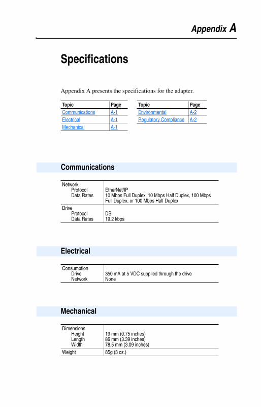
Appendix A
Specifications
Appendix A presents the specifications for the adapter.
Topic Page Topic PageCommunications A-1 Environmental A-2Electrical A-1 Regulatory Compliance A-2Mechanical A-1
Communications
NetworkProtocolData Rates
EtherNet/IP10 Mbps Full Duplex, 10 Mbps Half Duplex, 100 Mbps Full Duplex, or 100 Mbps Half Duplex
DriveProtocolData Rates
DSI19.2 kbps
Electrical
Consumption DriveNetwork
350 mA at 5 VDC supplied through the driveNone
Mechanical
DimensionsHeightLengthWidth
19 mm (0.75 inches)86 mm (3.39 inches)78.5 mm (3.09 inches)
Weight 85g (3 oz.)

A-2 Specifications
NOTE: This is a product of category C2 according to IEC 61800-3. In a domestic environment this product may cause radio interference in which case supplementary mitigation measures may be required.
Environmental
TemperatureOperatingStorage
-10 to 50°C (14 to 149°F)-40 to 85°C (-40 to 185°F)
Relative Humidity 5 to 95% non-condensingAtmosphere Important: Adapter must not be installed in an area
where the ambient atmosphere contains volatile or corrosive gas, vapors or dust. If the adapter is not going to be installed for a period of time, it must be stored in an area where it will not be exposed to a corrosive atmosphere.
Regulatory Compliance
Certification SpecificationUL UL508CcUL CAN / CSA C22.2 No. 14-M91CE EN50178 and EN61800-3CTick AS/NZS 2064, Group 1, Class A

Appendix B
Adapter Parameters
Appendix B provides information about the EtherNet/IP adapter parameters.
The parameters in the adapter are numbered consecutively. However, depending on which configuration tool you use, they may have different numbers.
Topic PageAbout Parameter Numbers B-1Parameter List B-1
About Parameter Numbers
Configuration Tool Numbering Scheme• DriveExplorer• DriveExecutive• HIM
The adapter parameters begin with parameter 1. For example, Parameter 01 - [Mode] is parameter 1 as indicated by this manual.
• Explicit Messaging• RSNetWorx for EtherNet/IP
Refer to Chapter 6, Using Explicit Messaging, and Appendix C, EtherNet/IP Objects, for details.
Parameter List
ParameterNo. Name and Description Details01 [Mode]
Displays the Single or Multi-Drive operating mode selected with the Operating Mode Switch (SW1) on the adapter.
Default: 0 = Single DriveValues: 0 = Single Drive
1 = Multiple DriveType: Read Only
02 [BOOTP]Configures the adapter to use BOOTP so that you can set its IP address, subnet mask, and gateway address with a BOOTP server.
Default: 1 = EnabledValues: 0 = Disabled
1 = EnabledType: Read/WriteReset Required: Yes

B-2 Adapter Parameters
03040506
[IP Addr Cfg 1][IP Addr Cfg 2][IP Addr Cfg 3][IP Addr Cfg 4]Sets the bytes in the IP address.
Important: To set the IP address using these parameters, Parameter 02 - [BOOTP] must be set to Disabled.
Default: 0Default: 0Default: 0Default: 0Minimum: 0Maximum: 255Type: Read/WriteReset Required: Yes
07080910
[Subnet Cfg 1][Subnet Cfg 2][Subnet Cfg 3][Subnet Cfg 4]Sets the bytes of the subnet mask.
Important: To set the subnet mask using these parameters, Parameter 02 - [BOOTP] must be set to Disabled.
Default: 0Default: 0Default: 0Default: 0Minimum: 0Maximum: 255Type: Read/WriteReset Required: Yes
11121314
[Gateway Cfg 1][Gateway Cfg 2][Gateway Cfg 3][Gateway Cfg 4]Sets the bytes of the gateway address.
Important: To set the gateway address using these parameters, Parameter 02 - [BOOTP] must be set to Disabled.
Default: 0Default: 0Default: 0Default: 0Minimum: 0Maximum: 255Type: Read/WriteReset Required: Yes
ParameterNo. Name and Description Details
255 . 255 . 255 . 255
[IP Addr Cfg 1]
[IP Addr Cfg 2]
[IP Addr Cfg 3]
[IP Addr Cfg 4]
255 . 255 . 255 . 255
[Subnet Cfg 1]
[Subnet Cfg 2]
[Subnet Cfg 3]
[Subnet Cfg 4]
255 . 255 . 255 . 255
[Gateway Cfg 1]
[Gateway Cfg 2]
[Gateway Cfg 3]
[Gateway Cfg 4]

Adapter Parameters B-3
15 [EN Rate Cfg]Sets the network data rate at which the adapter communicates.
Default: 0 = AutodetectValues: 0 = Autodetect
1 = 10 Mbps Full2 = 10 Mbps Half3 = 100 Mbps Full4 = 100 Mbps Half
Type: Read/WriteReset Required: Yes
16 [EN Rate Act]Displays the network data rate currently being used by the adapter.
Default: 0 = No LinkValues: 0 = No Link
1 = 10 Mbps Full2 = 10 Mbps Half3 = 100 Mbps Full4 = 100 Mbps Half
Type: Read Only17 [Reset Module]
No action if set to “Ready.” Resets the adapter if set to “Reset Module.” Restores the adapter to its factory default settings if set to “Set Defaults.” This parameter is a command. It will be reset to “0 = Ready” after the command has been performed.
Default: 0 = ReadyValues 0 = Ready
1 = Reset Module2 = Set Defaults
Type: Read/WriteReset Required: No
18 [Comm Flt Action]Sets the action that the adapter and drive will take if the adapter detects that Ethernet communications have been disrupted. This setting is effective only if I/O that controls the drive is transmitted through the adapter.
Default: 0 = FaultValues: 0 = Fault
1 = Stop2 = Zero Data3 = Hold Last4 = Send Flt Cfg
Type: Read/WriteReset Required: No
ParameterNo. Name and Description Details
!ATTENTION: Risk of injury or equipment damage exists. If the adapter is transmitting I/O that controls the drive, the drive may fault when you reset the adapter. Determine how your drive will respond before resetting a connected adapter.
!ATTENTION: Risk of injury or equipment damage exists. Parameter 18 - [Comm Flt Action] lets you determine the action of the adapter and connected drive if communications are disrupted. By default, this parameter faults the drive. You can set this parameter so that the drive continues to run. Precautions should be taken to ensure that the setting of this parameter does not create a risk of injury or equipment damage. When commissioning the drive, verify that your system responds correctly to various situations (for example, a disconnected drive).

B-4 Adapter Parameters
19 [Idle Flt Action]Sets the action that the adapter and drive will take if the adapter detects that the scanner is idle because the controller was switched to program mode. This setting is effective only if I/O that controls the drive is transmitted through the adapter.
Default: 0 = FaultValues: 0 = Fault
1 = Stop2 = Zero Data3 = Hold Last4 = Send Flt Cfg
Type: Read/WriteReset Required: No
20 [Flt Cfg Logic]Sets the Logic Command data that is sent to the drive if any of the following is true:
• Parameter 18 - [Comm Flt Action] is set to “Send Flt Cfg” and communications are disrupted.
• Parameter 19 - [Idle Flt Action] is set to “Send Flt Cfg” and the scanner is put into Program or Test mode.
The bit definitions will depend on the product to which the adapter is connected.
Default: 0000 0000 0000 0000Minimum: 0000 0000 0000 0000Maximum: 1111 1111 1111 1111Type: Read/WriteReset Required: No
21 [Flt Cfg Ref]Sets the Reference data that is sent to the drive if any of the following is true:
• Parameter 18 - [Comm Flt Action] is set to “Send Flt Cfg” and communications are disrupted.
• Parameter 19 - [Idle Flt Action] is set to “Send Flt Cfg” and the scanner is put into Program or Test mode.
Default: 0Minimum: 0Maximum: 65535Type: Read/WriteReset Required: No
22 [DSI I/O Cfg]Sets the configuration of the Drives that are active in the Multi-Drive mode. Identifies the connections that would be attempted on a reset or power cycle.
Default: 0Values: 0 = Drive 0
1 = Drives 0-1 2 = Drives 0-23 = Drives 0-34 = Drives 0-4
Type: Read/WriteReset Required: Yes
ParameterNo. Name and Description Details
!ATTENTION: Risk of injury or equipment damage exists. Parameter 19 - [Idle Flt Action] lets you determine the action of the adapter and connected drive if the scanner is idle. By default, this parameter faults the drive. You can set this parameter so that the drive continues to run. Precautions should be taken to ensure that the setting of this parameter does not create a risk of injury or equipment damage. When commissioning the drive, verify that your system responds correctly to various situations (for example, a disconnected drive).

Adapter Parameters B-5
23 [DSI I/O Act]Displays the Drives that are active in the Multi-Drive mode.
Default: xxx0 0000Bit Values: 0 = Drive Active
1 = Drive InactiveType: Read OnlyBit Definitions0 = Drive 0 Active1 = Drive 1 Active2 = Drive 2 Active3 = Drive 3 Active4 = Drive 4 Active5 = Not Used6 = Not Used7 = Not Used
2425262728
[Drv 0 Addr][Drv 1 Addr][Drv 2 Addr][Drv 3 Addr][Drv 4 Addr]
Sets the corresponding node addresses of the daisy-chained drives when the adapter Operating Mode Switch (SW1) is set for Multi-Drive operation.
Important: The settings for these parameters must match the Comm Node Addr parameter settings in the respective drives. Each setting must also be unique (no duplicate node address).
Default: 100Default: 101Default: 102Default: 103Default: 104Minimum: 1Maximum: 247Type: Read/WriteReset Required: Yes
29 [Web Enable]Displays the setting of the Web Pages Switch (SW2) on the adapter when the adapter was last reset.
Default: 0 = DisabledValues: 0 = Disabled
1 = EnabledType: Read Only
30 [Web Features]Sets the access to the Web interface and Web-configurable features.
Default: xxxx xx11Bit Values: 0 = Disabled
1 = EnabledType: Read/WriteReset Required: NoBit Definitions0 = E-mail Configuration1 = Process Display Configuration2-7 = Not used
ParameterNo. Name and Description Details
BitDefault 00000x xx
0123457 6
BitDefault 11xxxx xx
0123457 6

B-6 Adapter Parameters
Notes:

Appendix C
EtherNet/IP Objects
Appendix C provides information about the EtherNet/IP objects that can be accessed using Explicit Messages. For information on the format of Explicit Messages and example ladder logic programs, refer toChapter 6, Using Explicit Messaging.
Supported Data Types
ObjectClass Code
Page ObjectClass Code
PageHex. Dec. Hex. Dec.Identity Object 0x01 1 C-2 DPI Device Object 0x92 146 C-21Assembly Object 0x04 4 C-4 DPI Parameter Object 0x93 147 C-24Register Object 0x07 7 C-6 DPI Fault Object 0x97 151 C-28Parameter Object 0x0F 15 C-9 DPI Diagnostic Object 0x99 153 C-30Parameter Group Object 0x10 16 C-13 TCP/IP Interface Object 0xF5 245 C-32PCCC Object 0x67 103 C-15 Ethernet Link Object 0xF6 246 C-34
TIP: Refer to the EtherNet/IP specification for more information about EtherNet/IP objects. Information about the EtherNet/IP specification is available on the ODVA web site (http://www.odva.org).
Data Type DescriptionBYTE 8-bit unsigned integerWORD 16-bit unsigned integerDWORD 32-bit unsigned integerLWORD 64-bit unsigned integerSINT 8-bit signed integerUSINT 8-bit unsigned integerINT 16-bit signed integerUINT 16-bit unsigned integerDINT 32-bit signed integerUDINT 32-bit unsigned integerBOOL 8-bit value -- low bit is true or falseBOOL[n] Array of n bitsSTRING[n] Array of n charactersSHORT_STRING 1-byte length indicator + that many charactersSTRUCT Structure name only - no size in addition to elementsCONTAINER 32-bit parameter value - sign extended if necessaryTCHAR 8 or 16-bit characterREAL 32-bit floating point

C-2 EtherNet/IP Objects
Class Code
Instances (Single-Drive Mode)
The number of instances is fixed at three and is as shown below:
Instances (Multi-Drive Mode)
The number of instances is fixed at one and is as shown below:
Class Attributes
Identity Object
Hexadecimal Decimal0x01 1
Instance Description0 Class1 Host drive2 22-COMM-E3 22-SCM-232 or 22-HIM-* (when present)
Instance Description0 Class1 22-COMM-E
Attribute ID
Access Rule Name Data Type Description
1 Get Revision UINT 12 Get Max Instance UINT Total number of instances6 Get Max ID Number
of Class Attributes
UINT 7
7 Get Max ID Number of Instance Attributes
UINT 100

EtherNet/IP Objects C-3
Instance Attributes
Services
Identity Object (Continued)
Attribute ID
Access Rule Name Data Type Description
1 Get Vendor ID UINT 1 = Allen-Bradley2 Get Device Type UINT 1273 Get Product Code UINT Number identifying product
name and rating4 Get Revision:
MajorMinor
STRUCT of:USINTUSINT
Value variesValue varies
5 Get Status WORD Bit 0 = OwnedBit 2 = ConfiguredBit 10 = Recoverable faultBit 11 = Unrecoverable fault
6 Get Serial Number UDINT Unique 32-bit number7 Get Product Name SHORT_
STRING Product name and rating9 Get Configuration
Consistency Value
UINT CRC or checksum representing the configuration of the product
100 Get NVS Info STRUCT of:UDINTSHORT_STRING
First NVS instanceSub-assembly name
Service Code Implemented for: Service NameClass Instance
0x01 Yes Yes Get_Attributes_All0x05 No Yes Reset0x0E Yes Yes Get_Attribute_Single

C-4 EtherNet/IP Objects
Class Code
Instances
Class Attributes
Instance Attributes
Important: Setting an Assembly object attribute can be done only when the Control Timeout (class attribute 100) has been set to a non-zero value.
Assembly Object
Hexadecimal Decimal0x04 4
Instance Description1 All I/O data being read from the DSI drives (read-only)2 All I/O data written to the DSI drives (read/write)
Attribute ID Access Rule Name Data Type Description1 Get Revision UINT 22 Get Max Instance UINT 2100 Set Control
TimeoutUINT Control timeout in seconds
Attribute ID Access Rule Name Data Type Description1 Get Number of
MembersUINT 1
2 Get Member List ARRAY ofSTRUCT:
UINTUINTPacked
EPATH
Size of member dataSize of member pathMember path
3 Conditional (1)
(1) For instance 1, access rule for the data attribute is Get. For instance 2, it is Get/Set.
Data Array of Bits Data to be transferred4 Get Size UINT Size of assembly data in bits

EtherNet/IP Objects C-5
Services
Assembly Object (Continued)
Service CodeImplemented for:
Service NameClass Instance0x0E Yes Yes Get_Attribute_Single0x10 Yes Yes Set_Attribute_Single

C-6 EtherNet/IP Objects
Class Code
Instances
Register Object
Hexadecimal Decimal0x07 7
Instance Description Input/Output
Size(in bits)
1 Logic Command and Reference for all drives Out Varies (1)
2 Logic Status and Feedback for all drives In Varies (1)
3 Logic Command and Reference for Drive 0 Out 324 Logic Status and Feedback for Drive 0 In 325 Logic Command and Reference for Drive 1 Out 326 Logic Status and Feedback for Drive 1 In 327 Logic Command and Reference for Drive 2 Out 328 Logic Status and Feedback for Drive 2 In 329 Logic Command and Reference for Drive 3 Out 3210 Logic Status and Feedback for Drive 3 In 3211 Logic Command and Reference for Drive 4 Out 3212 Logic Status and Feedback for Drive 4 In 3213 Logic Command for all drives — mask-and-match register (2) Out Varies (1)
14 Logic Command for Drive 0 — mask-and-match register (2) Out 3215 Logic Command for Drive 1 — mask-and-match register (2) Out 3216 Logic Command for Drive 2 — mask-and-match register (2) Out 3217 Logic Command for Drive 3 — mask-and-match register (2) Out 3218 Logic Command for Drive 4 — mask-and-match register (2) Out 3219 Logic Command for Drive 0 Out 1620 Logic Status for Drive 0 In 1621 Reference for Drive 0 Out 1622 Feedback for Drive 0 In 1623 Logic Command for Drive 1 Out 1624 Logic Status for Drive 1 In 1625 Reference for Drive 1 Out 1626 Feedback for Drive 1 In 16
(1) The size for this Register Object instance is 32 bits per drive. For example, if the adapter is operating in Multi-Drive mode, and is configured with Drives 0 through 4, then the size is 160 bits.
(2) The structure for this Register Object instance is a Mask word followed by a Command word for each drive. The Logic Command for each drive is set to the value of the second word of the data where there are ones in the first word of the data.
Logic Command = (Logic Command and not Mask word) or (Command word and Mask word)

EtherNet/IP Objects C-7
Instances (Continued)
Class Attributes
Register Object (Continued)
Instance Description Input/Output
Size (in bits)
27 Logic Command for Drive 2 Out 1628 Logic Status for Drive 2 In 1629 Reference for Drive 2 Out 1630 Feedback for Drive 2 In 1631 Logic Command for Drive 3 Out 1632 Logic Status for Drive 3 In 1633 Reference for Drive 3 Out 1634 Feedback for Drive 3 In 1635 Logic Command for Drive 4 Out 1636 Logic Status for Drive 4 In 1637 Reference for Drive 4 Out 1638 Feedback for Drive 4 In 16
Attribute ID
Access Rule Name Data Type Description
1 Get Revision UINT 12 Get Max Instance UINT 383 Get Number of Instances UINT 38100 Set Control Timeout UINT Control timeout in seconds

C-8 EtherNet/IP Objects
Instance Attributes
Important: Setting a Register object attribute can be done only when the Control Timeout (class attribute 100) has been set to a non-zero value.
Register Object (Continued)
Attribute ID Access Rule Name Data Type Description1 Get Bad Flag BOOL If set to 1, then attribute 4
contains invalid, bad or otherwise corrupt data.0 = good1 = bad
2 Get Direction BOOL Direction of data transfer0 = Input (Drive to EtherNet/IP)1 = Output (EtherNet/IP to Drive)
3 Get Size UINT Size of register data in bits4 Conditional (1)
(1) The access rule of Set is optional if attribute 2, Direction = 1. If Direction = 0, the access rule is Get.
Data ARRAY of BITS
Data to be transferred
Service CodeImplemented for:
Service NameClass Instance0x0E Yes Yes Get_Attribute_Single0x10 Yes Yes Set_Attribute_Single

EtherNet/IP Objects C-9
Class Code
Instances (Single-Drive Mode)
The number of instances is as shown below:
Instances (Multi-Drive Mode)
The number of instances is as shown below:
In addition, the parameters for the other DSI devices can be accessed using the instance-offset encoding shown in the table below:
Parameter Object
Hexadecimal Decimal0x0F 15
Instance Description0 Class1 Drive Parameter 1
n Drive Parameter n (1)
(1) n represents the number of parameters in the drive.
n + 1 Adapter Parameter 1
n + m Adapter Parameter m (2)
(2) m represents the number of parameters in the adapter.
Instance Description0 Class1 Adapter Parameter 1
m Adapter Parameter m (1)
(1) m represents the number of parameters in the adapter.
Instances (Dec.) Single-Drive Mode Multi-Drive Mode16384 – 17407 Instances 0 – 1023 in the adapter Instances 0 – 1023 in the adapter17408 – 18431 Instances 0 – 1023 in the drive Instances 0 – 1023 in Drive 018432 – 19455 Not supported Instances 0 – 1023 in Drive 119456 – 20479 Not supported Instances 0 – 1023 in Drive 220480 – 21503 Not supported Instances 0 – 1023 in Drive 321504 – 22527 Not supported Instances 0 – 1023 in Drive 4

C-10 EtherNet/IP Objects
Class Attributes
Parameter Object (Continued)
Attribute ID
Access Rule Name Data Type Description
1 Get Revision UINT 12 Get Max Instance UINT Number of parameters8 Get Parameter
Class Descriptor
WORD 0 = False, 1 = TrueBit 0 = Supports parameter instancesBit 1 = Supports full attributesBit 2 = Must do NVS save commandBit 3 = Parameters are stored in NVS
9 Get Configuration Assembly Instance
UINT 0
10 Get Native Language
USINT 0 = English1 = French2 = Spanish3 = Italian4 = German5 = Japanese6 = Portuguese7 = Mandarin Chinese8 = Russian9 = Dutch

EtherNet/IP Objects C-11
Instance Attributes
Parameter Object (Continued)
Attribute ID
Access Rule Name Data Type Description
1 (1)
(1) Access rule is defined in bit 4 of instance attribute 4. 0 = Get/Set, 1 = Get.
Parameter Value (2)
(2) Specified in descriptor, data type, and data size.
(3)
(3) Value varies based on parameter instance.
2 Get Link Path Size USINT 0 = No link specifiedn = The size of Attribute 3 in bytes
3 Get Link Path (4)
(4) Refer to the CIP Common specification for a description of the link path.
4 Get Descriptor WORD 0 = False, 1 = TrueBit 1 = Supports ENUMsBit 2 = Supports scalingBit 3 = Supports scaling linksBit 4 = Read onlyBit 5 = MonitorBit 6 = Extended precision scaling
5 Get Data Type USINT 0xC2 = SINT (8-bits)0xC3 = INT (16-bits)0xC4 = DINT (32-bits)0xC6 = USINT (8-bits)0xC7 = UINT (16-bits)0xCA = REAL (32-bits)0xD2 = WORD (16-bits)
6 Get Data Size USINT (3)
7 Get Parameter Name String
SHORT_STRING
(3)
8 Get Units String SHORT_STRING
(3)
9 Get Help String SHORT_STRING
Null string
10 Get Minimum Value (1) (3)
11 Get Maximum Value (1) (3)
12 Get Default Value (1) (3)
13 Get Scaling Multiplier UINT (3)
14 Get Scaling Divisor UINT (3)
15 Get Scaling Base UINT (3)
16 Get Scaling Offset UINT (3)
17 Get Multiplier Link UINT (3)
18 Get Divisor Link UINT (3)
19 Get Base Link UINT (3)
20 Get Offset Link UINT (3)
21 Get Decimal Precision USINT (3)

C-12 EtherNet/IP Objects
Services
Parameter Object (Continued)
Service CodeImplemented for:
Service NameClass Instance0x01 Yes Yes Get_Attribute_All0x05 Yes No Reset0x0E Yes Yes Get_Attribute_Single0x10 No Yes Set_Attribute_Single0x4B No Yes Get_Enum_String

EtherNet/IP Objects C-13
Class Code
Instances
The number of instances depends on the number of groups in the device. A group of adapter parameters is appended to the list of groups in the device. The total number of groups can be read in Instance 0, Attribute 2.
Class Attributes
Parameter Group Object
Hexadecimal Decimal0x10 16
Number Description0 Class Attributes1 Drive Group 1 Attributes
… …
n Drive Group n Attributes (1)
(1) n represents the number of parameter groups in the drive.
n + 1 Adapter Group Attributes
Attribute ID
Access Rule Name
Data Type Description
1 Get Parameter group version
UINT 1
2 Get Max Instance UINT Total number of groups8 Set Native
LanguageUSINT 0 = English
1 = French2 = Spanish (Mexican)3 = Italian4 = German5 = Japanese6 = Portuguese7 = Mandarin Chinese8 = Russian9 = Dutch

C-14 EtherNet/IP Objects
Instance Attributes
Services
Parameter Group Object (Continued)
Attribute ID
Access Rule Name Data Type Description
1 Get Group Name String SHORT_STRING
Group name
2 Get Number of Members in Group
UINT Number of parameters in group.
3 Get 1st Parameter Number in Group
UINT (1)
(1) Value varies based on group instance.
4 Get 2nd Parameter Number in Group
UINT (1)
n Get … UINT (1)
Service CodeImplemented for:
Service NameClass Instance0x0E Yes Yes Get_Attribute_Single0x01 Yes Yes Get_Attributes_All

EtherNet/IP Objects C-15
Class Code
Instances
Supports Instance 1.
Class Attributes
Not supported.
Instance Attributes
Not supported.
Services
Message Structure for Execute_PCCC
PCCC Object
Hexadecimal Decimal0x67 103
Service CodeImplemented for:
Service NameClass Instance0x4B No Yes Execute_PCCC0x4C No Yes Execute_DH+
Request Response
NameDataType Description Name
DataType Description
Length USINT Length of requestor ID
Length USINT Length of requestor ID
Vendor UINT Vendor number of requestor
Vendor UINT Vendor number of requestor
Serial Number
UDINT ASA serial number of requestor
Serial Number
UDINT ASA serial number of requestor
Other Product Specific
Identifier of user, task, etc. on the requestor
Other Product Specific
Identifier of user, task, etc. on the requestor
CMD USINT Command byte CMD USINT Command byte
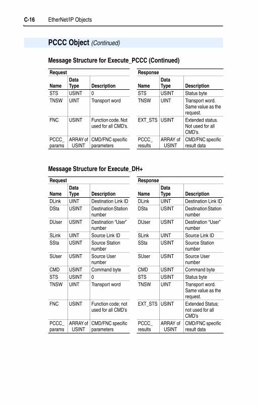
C-16 EtherNet/IP Objects
Message Structure for Execute_PCCC (Continued)
Message Structure for Execute_DH+
PCCC Object (Continued)
Request Response
NameDataType Description Name
DataType Description
STS USINT 0 STS USINT Status byteTNSW UINT Transport word TNSW UINT Transport word.
Same value as the request.
FNC USINT Function code. Not used for all CMD’s.
EXT_STS USINT Extended status. Not used for all CMD’s.
PCCC_params
ARRAY of USINT
CMD/FNC specific parameters
PCCC_results
ARRAY of USINT
CMD/FNC specific result data
Request Response
NameDataType Description Name
DataType Description
DLink UINT Destination Link ID DLink UINT Destination Link IDDSta USINT Destination Station
numberDSta USINT Destination Station
numberDUser USINT Destination “User”
numberDUser USINT Destination “User”
numberSLink UINT Source Link ID SLink UINT Source Link IDSSta USINT Source Station
numberSSta USINT Source Station
numberSUser USINT Source User
numberSUser USINT Source User
numberCMD USINT Command byte CMD USINT Command byteSTS USINT 0 STS USINT Status byteTNSW UINT Transport word TNSW UINT Transport word.
Same value as the request.
FNC USINT Function code; not used for all CMD’s
EXT_STS USINT Extended Status; not used for all CMD’s
PCCC_params
ARRAY of USINT
CMD/FNC specific parameters
PCCC_results
ARRAY of USINT
CMD/FNC specific result data

EtherNet/IP Objects C-17
The adapter supports the following PCCC command types:
See DF1 Protocol and Command Set Manual, Allen-Bradley Publication No. 1770-6.5.16.
N-Files
PCCC Object (Continued)
CMD FNC Description0x06 0x03 Identify host and some status0x0F 0x67 PLC-5 typed write0x0F 0x68 PLC-5 typed read0x0F 0x95 Encapsulate other protocol0x0F 0xA2 SLC 500 protected typed read with 3 address fields0x0F 0xAA SLC 500 protected typed write with 3 address fields0x0F 0xA1 SLC 500 protected typed read with 2 address fields0x0F 0xA9 SLC 500 protected typed write with 2 address fields0x0F 0x00 Word range read0x0F 0x01 Word range write
N-File DescriptionN40 This N-file lets you use Emulated Block Transfer messages to read and write
many types of DPI messages. To use Emulated Block Transfer messages, you send a Write message to N40:0 – N40:63, wait until the adapter responds with a reply message, and then read the response data in N40:0 – N40:63 with a Read message.
For details about Block Transfer messages and the data required for each byte in the N-File, refer to the Remote I/O Adapter User Manual, Publication 20COMM-UM004….
Bits 15 to 8 are the Most Significant Byte. Bits 7 to 0 are the Least Significant Byte.
Write ReadBits 15 0 15 0
N40:0 0x00 Length (in Bytes) 0x00 Length (in Bytes)N40:1 DPI Port (1)
(1) Use the following DPI Port Assignment table to determine the value for the DPI port.
0x81 Status Size Status TypeN40:2 0x00 CIP Service Data
(length varies based on message)N40:3 CIP ClassN40:4 CIP InstanceN40:5 CIP AttributeN40:6 Data
(length varies based on message)…
N40:63

C-18 EtherNet/IP Objects
N-Files (Continued)
DPI Port Assignments
PCCC Object (Continued)
DPI Port No. Single-Drive Mode Multi-Drive Mode0 The drive Drive 01 The adapter Drive 12 The slave Drive 23 Not supported Drive 34 Not supported Drive 45 Not supported The adapter
N-File Description
N41
For Single-Drive Mode Only
This N-file lets you read and write control I/O messages. You can write control I/O messages only when all of the following conditions are true:
• The adapter is not receiving I/O from a scanner. For example, there is no scanner on the network, the scanner is in idle (program) mode, the scanner is faulted, or the adapter is not mapped to the scanner.
• The value of N42:3 is set to a non-zero value.
Write ReadN41:0N41:1N41:2
Logic Command WordUnusedReference
Logic Status WordUnusedFeedback
N42 This N-file lets you read and write some values configuring the portN42:3 Time-out (read/write): Time (in seconds) allowed between messages to
the N41 or N44 file. If the adapter does not receive a message in the specified time, it performs the fault action configured in its [Comm Flt Action] parameter.
N42:7 Adapter Port Number (read only): DPI port on the drive to which the adapter is connected.
N42:8 Peer Adapters (read only): Bit field of devices having DPI Peer capabilities.

EtherNet/IP Objects C-19
N-Files (Continued)
PCCC Object (Continued)
N-File Description
N44
For Multi-Drive Mode Only
This N-file lets you read and write control I/O messages. You can write control I/O messages only when all of the following conditions are true:
• The adapter is not receiving I/O from a scanner. For example, there is no scanner on the network, the scanner is in idle (program) mode, the scanner is faulted, or the adapter is not mapped to the scanner.
• The value of N42:3 is set to a non-zero value.
Write ReadN44:0 Drive 0 Logic Command Drive 0 Logic StatusN44:1 Unused UnusedN44:2 Drive 0 Reference Drive 0 FeedbackN44:3 Drive 1 Logic Command Drive 1 Logic StatusN44:4 Drive 1 Reference Drive 1 FeedbackN44:5 Drive 2 Logic Command Drive 2 Logic StatusN44:6 Drive 2 Reference Drive 2 FeedbackN44:7 Drive 3 Logic Command Drive 3 Logic StatusN44:8 Drive 3 Reference Drive 3 FeedbackN44:9 Drive 4 Logic Command Drive 4 Logic StatusN44:10 Drive 4 Reference Drive 4 Feedback

C-20 EtherNet/IP Objects
N-Files (Continued)
Important: If your controller or HMI platform supports CIP messaging, use the CIP Parameter object to get and set parameters.
PCCC Object (Continued)
N-File DescriptionN10 – N18 These N-files let you read and write parameter values in the drive and the
adapter.
Single-Drive Mode Multi-Drive ModeN10:0N10:1 – 999
Number of parameters in the driveDrive parameters 1 – 999
Number of parameters in Drive 0Drive 0 parameters 1 - 999
N11:0 – 999 Drive parameters 1000 – 1999 Drive 0 parameters 1000 - 1999N12:0 – 999 Drive parameters 2000 – 2999 Drive 0 parameters 2000 - 2999N13:0 Number of parameters in this
adapterNumber of parameters in this adapter
N13:1 – 999 Parameters 1 – 999 in this adapter Parameters 1 – 999 in this adapterN14:0 Number of parameters in this
adapterNumber of parameters in Drive 1
N14:1 – 999 Parameters 1 – 999 in this adapter Drive 1 parameters 1 – 999N15:0 Number of parameters in the slave Number of parameters in Drive 2N15:1 – 999 Parameters 1 – 999 in the slave Drive 2 parameters 1 – 999N16:0 Not supported Number of parameters in Drive 3N16:1 – 999 Not supported Drive 3 parameters 1 – 999N17:0 Not supported Number of parameters in Drive 4N17:1 – 999 Not supported Drive 4 parameters 1 – 999N18:0 Not supported Number of parameters in this
adapterN18:1 – 999 Not supported Parameters 1 – 999 in this adapter

EtherNet/IP Objects C-21
Class Code
Instances
The number of instances depends on the number of components in the device. The total number of components can be read in Instance 0, Class Attribute 4.
Class Attributes
DPI Device Object
Hexadecimal Decimal0x92 146
Instances (Dec.) Single-Drive Mode Multi-Drive Mode0 – 16383 Instances 0 – 16383 in the drive Instances 0 – 16383 in Drive 016384 – 17407 Instances 0 – 1023 in the adapter Instances 0 – 1023 in the adapter17408 – 18431 Instances 0 – 1023 in the adapter Instances 0 – 1023 in Drive 118432 – 19455 Instances 0 – 1023 in the slave Instances 0 – 1023 in Drive 219456 – 20479 Not supported Instances 0 – 1023 in Drive 320480 – 21503 Not supported Instances 0 – 1023 in Drive 421504 – 22527 Not supported Instances 0 – 1023 in the adapter
Attribute ID
Access Rule Name Data Type Description
0 Get Family Code BYTE Code identifying the device.1 Get Family Text STRING[16] Text identifying the device.2 Set Language Code BYTE 0 = English
1 = French2 = Spanish3 = Italian4 = German5 = Japanese6 = Portuguese7 = Mandarin Chinese8 = Russian9 = Dutch
3 Get Product Series BYTE 1 = A2 = B …
4 Get Number of Components
BYTE Number of components (e.g., main control board, I/O boards) in the device.

C-22 EtherNet/IP Objects
Class Attributes (Continued)
DPI Device Object (Continued)
Attribute ID
Access Rule Name Data Type Description
5 Set User Definable Text
STRING[16] Text identifying the device with a user-supplied name
6 Get Status Text STRING[12] Text describing the status of the device.7 Get Configuration
CodeBYTE Identification of variations.
8 Get Configuration Text STRING[16] Text identifying a variation of a family device.
9 Get Brand Code WORD 0x0001 = Allen-Bradley11 Get NVS Checksum WORD Checksum of the Non-Volatile Storage in a
device.12 Get Class Revision WORD 2 = DPI13 Get Character Set
CodeBYTE 0 = SCANport HIM
1 = ISO 8859-1 (Latin 1)2 = ISO 8859-2 (Latin 2)3 = ISO 8859-3 (Latin 3)4 = ISO 8859-4 (Latin 4)5 = ISO 8859-5 (Cyrillic)6 = ISO 8859-6 (Arabic)7 = ISO 8859-7 (Greek)8 = ISO 8859-8 (Hebrew)9 = ISO 8859-9 (Turkish)10 = ISO 8859-10 (Nordic)255 = ISO 10646 (Unicode)
15 Get Languages Supported
STRUCT of:BYTEBYTE[n]
Number of LanguagesLanguage Codes (See Class Attribute 2)
16 Get Date of Manufacture
STRUCT of:WORDBYTEBYTE
YearMonthDay
17 Get Product Revision STRUCT of: BYTEBYTE
Major Firmware ReleaseMinor Firmware Release
18 Get Serial Number DWORD Value between 0x00 and 0xFFFFFFFF

EtherNet/IP Objects C-23
Instance Attributes
Services
DPI Device Object (Continued)
Attribute ID
Access Rule Name Data Type Description
3 Get Component Name
STRING[32] Name of the component
4 Get Component Firmware Revision
STRUCT of:BYTEBYTE
Major RevisionMinor Revision
5 Get Component Hardware Change Number
BYTE
8 Get Component Serial Number
DWORD Value between 0x00 and 0xFFFFFFFF
Service CodeImplemented for:
Service NameClass Instance0x0E Yes Yes Get_Attribute_Single0x10 Yes Yes Set_Attribute_Single

C-24 EtherNet/IP Objects
Class Code
Instances
The number of instances depends on the number of parameters in the device. The total number of parameters can be read in Instance 0, Attribute 0.
Class Attributes
DPI Parameter Object
Hexadecimal Decimal0x93 147
Instances (Dec.) Single-Drive Mode Multi-Drive Mode0 – 16383 Instances 0 – 16383 in the drive Instances 0 – 16383 in Drive 016384 – 17407 Instances 0 – 1023 in the adapter Instances 0 – 1023 in the adapter17408 – 18431 Instances 0 – 1023 in the adapter Instances 0 – 1023 in Drive 118432 – 19455 Instances 0 – 1023 in the slave Instances 0 – 1023 in Drive 219456 – 20479 Not supported Instances 0 – 1023 in Drive 320480 – 21503 Not supported Instances 0 – 1023 in Drive 421504 – 22527 Not supported Instances 0 – 1023 in the adapter
Attribute ID
Access Rule Name Data Type Description
0 Get Number of Instances
WORD Number of parameters in the device
1 Set Write Protect Password
WORD 0 = Password disabledn = Password
2 Set NVS Command Write
BYTE 0 = No Operation1 = Store values in active memory to NVS2 = Load values in NVS to active memory3 = Load default values to active memory
3 Get NVS Parameter Value Checksum
WORD Checksum of all parameter values in a user set in NVS
4 Get NVS Link Value Checksum
WORD Checksum of parameter links in a user set in NVS
5 Get First Accessible Parameter
WORD First parameter available if parameters are protected by passwords. A “0” indicates all parameters are protected.
7 Get Class Revision WORD 2 = DPI8 Get First Parameter
Processing ErrorWORD The first parameter that has been written
with a value outside of its range. A “0” indicates no errors.
9 Set Link Command BYTE 0 = No Operation1 = Clear All Parameter Links (This does
not clear links to function blocks.)

EtherNet/IP Objects C-25
Instance Attributes
DPI Parameter Object (Continued)
Attribute ID
Access Rule Name Data Type Description
7 Get DPI Online Read Full
STRUCT of:BOOL[32]CONTAINER(1)
CONTAINERCONTAINERCONTAINERWORDWORDSTRING[4]UINTUINTUINTINTBYTE[3]BYTESTRING[16]
Descriptor (Refer to pages C-26 – C-27)Parameter valueMinimum valueMaximum valueDefault valueNext parameterPrevious parameterUnits (e.g., Amp, Hz)Multiplier (2)
Divisor (2)
Base (2)
Offset (2)
Link (source of the value) (0 = no link)Always zero (0)Parameter name
8 Get DPI Descriptor BOOL[32] Descriptor (Refer to pages C-26 – C-27)9 Get/Set DPI Parameter
ValueVarious Parameter value in NVS. (3)
10 Get/Set DPI RAM Parameter Value
Various Parameter value in temporary memory.
11 Get/Set DPI Link BYTE[3] Link (parameter or function block that is the source of the value) (0 = no link)
12 Get Help Object Instance
WORD ID for help text for this parameter
13 Get DPI Read Basic STRUCT of:BOOL[32]CONTAINERCONTAINERCONTAINERCONTAINERSTRING[16]STRING[4]
Descriptor (Refer to pages C-26 – C-27)Parameter valueMinimum valueMaximum valueDefault valueParameter nameUnits (e.g., Amp, Hz)
14 Get DPI Parameter Name
STRING[16] Parameter name
15 Get DPI Parameter Alias
STRING[16] Customer supplied parameter name. Only supported by PowerFlex 700S at time of publication.
16 Get Parameter Processing Error
BYTE 0 = No error1 = Value is less than the minimum2 = Value is greater than the maximum
(1) A CONTAINER is a 32-bit block of data that contains the data type used by a parameter value. If signed, the value is sign extended. Padding is used in the CONTAINER to ensure that it is always 32-bits.
(2) This value is used in the formulas used to convert the parameter value between display units and internal units. Refer to Formulas for Converting on page C-27.
(3) Do NOT continually write parameter data to NVS. Refer to the attention on page 6-1.

C-26 EtherNet/IP Objects
Descriptor Attributes
DPI Parameter Object (Continued)
Bit Name Description0 Data Type (Bit 1) Right bit is least significant bit (0).
000 = BYTE used as an array of Boolean001 = WORD used as an array of Boolean010 = BYTE (8-bit integer)011 = WORD (16-bit integer)100 = DWORD (32-bit integer)101 = TCHAR (8-bit (not unicode) or 16-bits (unicode))110 = REAL (32-bit floating point value)111 = Use bits 16, 17, 18
1 Data Type (Bit 2)
2 Data Type (Bit 3)
3 Sign Type 0 = unsigned1 = signed
4 Hidden 0 = visible 1 = hidden
5 Not a Link Sink 0 = Parameter can sink a link1 = Parameter cannot sink a link
6 Not Recallable 0 = Recallable from NVS1 = Not Recallable from NVS
7 ENUM 0 = No ENUM text1 = ENUM text
8 Writable 0 = Read only1 = Read/write
9 Not Writable When Enabled
0 = Writable when enabled (e.g., drive running)1 = Not writable when enabled
10 Instance 0 = Parameter value is not a Reference to anotherparameter
1 = Parameter value refers to another parameter11 Reserved Must be zero12 Decimal Place (Bit 0) Number of digits to the right of the decimal point.
0000 = 01111 = 15
13 Decimal Place (Bit 1)14 Decimal Place (Bit 2)15 Decimal Place (Bit 3)16 Extended
Data Type (Bit 1)Right bit is least significant bit (16).000 = Reserved001 = DWORD used as an array of Boolean010 = Reserved011 = Reserved100 = Reserved101 = Reserved110 = Reserved111 = Reserved
17 ExtendedData Type (Bit 2)
18 ExtendedData Type (Bit 2)

EtherNet/IP Objects C-27
Descriptor Attributes (Continued)
Formulas for ConvertingDisplay Value = ((Internal Value + Offset) x Multiplier x Base) / (Divisor x 10Decimal Places)
Internal Value = ((Display Value x Divisor x 10Decimal Places) / (Multiplier x Base)) - Offset
Common Services
Object Specific Services
The table below lists the parameters for the Get_Attributes_Scattered and Set_Attributes_Scattered object-specific service:
Important: The STRUCT may repeat up to 64 times in a single message.
DPI Parameter Object (Continued)
Bit Name Description19 Parameter Exists Reserved20 Not Used Reserved21 Formula Links Reserved22 Access Level (Bit 1) Reserved23 Access Level (Bit 2) Reserved24 Access Level (Bit 3) Reserved25 Writable ENUM Reserved26 Not a Link Source 0 = Parameter can be a source for a link
1 = Parameter cannot be a source for a link27 Enhanced Bit ENUM Reserved28 Enhanced ENUM Reserved29 Not Used Reserved30 Not Used Reserved31 Not Used Reserved
Service CodeImplemented for:
Service NameClass Instance0x0E Yes Yes Get_Attribute_Single0x10 Yes Yes Set_Attribute_Single
Service Code Service Name0x32 Get_Attributes_Scattered (1)
(1) The instance and attribute are ignored for these services.
0x34 Set_Attributes_Scattered (1)
Name Data Type DescriptionScattered Parameters STRUCT of —Parameter Number WORD Parameter to read or writeParameter Value WORD Parameter value to read or write (zero when reading)

C-28 EtherNet/IP Objects
Class Code
Products such as PowerFlex drives use this object for faults. Adapters use this object for events.
Instances
The number of instances depends on the maximum number of faults or events supported in the queue. The maximum number of faults/events can be read in Instance 0, Attribute 2.
Class Attributes
DPI Fault Object
Hexadecimal Decimal0x97 151
Instances (Dec.) Single-Drive Mode Multi-Drive Mode0 – 16383 Instances 0 – 16383 in the drive Instances 0 – 16383 in Drive 016384 – 17407 Instances 0 – 1023 in the adapter Instances 0 – 1023 in the adapter17408 – 18431 Instances 0 – 1023 in the adapter Instances 0 – 1023 in Drive 118432 – 19455 Instances 0 – 1023 in the slave Instances 0 – 1023 in Drive 219456 – 20479 Not supported Instances 0 – 1023 in Drive 320480 – 21503 Not supported Instances 0 – 1023 in Drive 421504 – 22527 Not supported Instances 0 – 1023 in the adapter
Attribute ID
Access Rule Name Data Type Description
1 Get Class Revision WORD Revision of object2 Get Number of
InstancesWORD Maximum number of faults/events that the
device can record in its queue3 Set Fault Command
WriteBYTE 0 = No Operation
1 = Clear Fault/Event2 = Clear Fault/Event Queue3 = Reset Device
4 Get Fault Trip Instance Read
WORD Fault that tripped the device. For adapters, this value is always 1 when faulted.
5 Get Fault Data List STRUCT of:BYTEBYTEWORD[n]
Reserved
6 Get Number of Recorded Faults
WORD Number of faults/events in the queue. A “0” indicates the fault queue is empty.
7 Get Fault Parameter Reference
WORD Reserved

EtherNet/IP Objects C-29
Instance Attributes
Services
DPI Fault Object (Continued)
Attribute ID
Access Rule Name Data Type Description
0 Get Full/All Information
STRUCT of:WORD
STRUCT of:BYTEBYTESTRING[16]
STRUCT of:LWORDBOOL[16]
WORDCONTAINER[n]
Fault codeFault sourceDPI port DPI Device ObjectFault textFault time stampTimer value (0 = Timer not supported)BOOL[0]: (0 = invalid data, 1 = valid data)BOOL[1]: (0 = elapsed time, 1 = real time)BOOL[2 - 15]: Not usedReservedReserved
1 Get Basic Information
STRUCT of:WORD
STRUCT of:BYTEBYTE
STRUCT of:LWORDBOOL[16]
Fault codeFault sourceDPI portDPI Device ObjectFault time stampTimer value (0 = Timer not supported)BOOL[0]: (0 = invalid data, 1 = valid data)BOOL[1]: (0 = elapsed time, 1 = real time)BOOL[2 - 15]: Not used
Service CodeImplemented for:
Service NameClass Instance0x0E Yes Yes Get_Attribute_Single0x10 Yes Yes Set_Attribute_Single

C-30 EtherNet/IP Objects
Class Code
Instances
The number of instances depends on the maximum number of diagnostic items in the device. The total number of diagnostic items can be read in Instance 0, Attribute 2.
Class Attributes
DPI Diagnostic Object
Hexadecimal Decimal0x99 153
Instances (Dec.) Single-Drive Mode Multi-Drive Mode0 – 16383 Instances 0 – 16383 in the drive Instances 0 – 16383 in Drive 016384 – 17407 Instances 0 – 1023 in the adapter Instances 0 – 1023 in the adapter17408 – 18431 Instances 0 – 1023 in the adapter Instances 0 – 1023 in Drive 118432 – 19455 Instances 0 – 1023 in the slave Instances 0 – 1023 in Drive 219456 – 20479 Not supported Instances 0 – 1023 in Drive 320480 – 21503 Not supported Instances 0 – 1023 in Drive 421504 – 22527 Not supported Instances 0 – 1023 in the adapter
Attribute ID
Access Rule Name Data Type Description
1 Get Class Revision WORD 12 Get Number of
InstancesWORD Number of diagnostic items in the
device3 Get ENUM Offset WORD DPI ENUM object instance offset

EtherNet/IP Objects C-31
Instance Attributes
Services
DPI Diagnostic Object (Continued)
Attribute ID
Access Rule Name Data Type Description
0 Get Full/All Info STRUCT of:BOOL[32]CONTAINER (1)
CONTAINERCONTAINERCONTAINERWORDWORDSTRING[4]UINTUINTUINTINTDWORDSTRING[16]
Descriptor (Refer to pages C-26 – C-27)ValueMinimum valueMaximum valueDefault valuePad WordPad WordUnits (e.g., Amp, Hz)Multiplier (2)
Divisor (2)
Base (2)
Offset (2)
Link (source of the value) (0 = no link)Always zero (0)Parameter name
1 Get/Set Value Various Diagnostic item value
(1) A CONTAINER is a 32-bit block of data that contains the data type used by a value. If signed, the value is sign extended. Padding is used in the CONTAINER to ensure that it is always 32-bits.
(2) This value is used in the formulas used to convert the value between display units and internal units. Refer to Formulas for Converting on page C-27.
Service CodeImplemented for:
Service NameClass Instance0x0E Yes Yes Get_Attribute_Single0x10 Yes Yes Set_Attribute_Single

C-32 EtherNet/IP Objects
Class Code
Instances
The adapter supports one instance of the TCP/IP Interface object.
Class Attributes
Instance Attributes
TCP/IP Interface Object
Hexadecimal Decimal0xF5 245
Number Description0 Class Attributes1 Object Attributes
Attribute ID
Access Rule Name Data Type Description
1 Get Revision UINT The revision of this object
Attribute ID
Access Rule Name Data Type Description
1 Get Status of TCP/IP Network Interface
DWORD 0 = Not configured1 = Valid configuration2 to 15 = Reserved
2 Get Configuration Capability
DWORD Bit | Value (0 = False, 1 = True)0 = Supports BOOTP1 = DNS Client (Able to resolve
host names by query to DNS server)
2 = DHCP Client (Able to obtain network configuration through DHCP)
3 = DHCP-DNS Update (Able to send its host name in the DHCP request)
4 = Configuration Settable (Able to set the network configuration via TCP/IP)
5 to 31 = Reserved

EtherNet/IP Objects C-33
Instance Attributes (Continued)
Services
TCP/IP Interface Object (Continued)
Attribute ID
Access Rule Name Data Type Description
3 Set Configuration Control
DWORD Bit | (Value)1 – 3 = Startup configuration
(0 = Use configuration saved in NVS)(1 = Obtain configuration via BOOTP)(2 = Obtain configuration via DHCP)(3 to 15 = Reserved)
4 = DNS Enabled (Resolves host names by query to DNS server)
5 to 31 = Reserved4 Get Physical Link
ObjectSTRUCT of:
UINTPadded EPATH
Path sizePath
5 Get Interface Configuration
STRUCT ofUDINTUDINTUDINTUDINTUDINTSTRING
Adapter’s IP addressAdapter’s subnet maskAdapter’s gateway addressPrimary name serverSecondary name serverDefault domain name
6 Get Host Name STRING Host name when using DHCP
Service CodeImplemented for:
Service NameClass Instance0x0E Yes Yes Get_Attribute_Single0x10 No Yes Set_Attribute_Single

C-34 EtherNet/IP Objects
Class Code
Instances
The adapter supports one instance of the TCP/IP Interface object.
Class Attributes
Instance Attributes
Ethernet Link Object
Hexadecimal Decimal0xF6 246
Number Description0 Class Attributes1 Object Attributes
Attribute ID
Access Rule Name Data Type Description
1 Get Revision UINT The revision of this object
Attribute ID
Access Rule Name Data Type Description
1 Get Interface Speed
UDINT Speed in megabits per second (Mbps)
2 Get Interface Flags
DWORD Bit | (Value)0 = Link status (0 = inactive, 1 = active)1 = Duplex (0 = half duplex, 1 = full duplex)2 to 31 = Reserved
3 Get Physical Address
USINT[6] MAC address (XX-XX-XX-XX-XX-XX)The first octet (USINT[0]) is on the left.

EtherNet/IP Objects C-35
Instance Attributes (Continued)
Services
Ethernet Link Object (Continued)
Attribute ID
Access Rule Name Data Type Description
4 Get Interface Counters
STRUCT of:UDINTUDINTUDINTUDINTUDINTUDINTUDINTUDINTUDINTUDINTUDINT
Octets receivedUnicast packets receivedNon-unicast packets receivedInbound packets received but discardedInbound packets with errors (not discarded)Inbound packets with unknown protocolOctets sentUnicast packets sentNon-unicast packets sentOutbound packets discardedOutbound packets with errors
5 Get Media Counters
STRUCT of:UDINTUDINTUDINTUDINTUDINTUDINTUDINTUDINTUDINTUDINTUDINTUDINT
RX = Received, TX = TransmittedRX frames not having integral number of octets longRX frames not passing FCS checkTX frames having one collisionTX frames having multiple collisionsNumber of times of SQE test error messageTX Frames delayed first attempt by busy mediumCollisions detected later than 512 bit-times in trans.TX frames failing due to excessive collisionsTX frames failing due to intern MAC sublayer TX errorTimes of carrier sense condition loss during trans.RX frames exceeding the maximum frame sizeRX frames failing due to intern MAC sublayer RX error
Service CodeImplemented for:
Service NameClass Instance0x0E Yes Yes Get_Attribute_Single0x4C No Yes Get_and_Clear

C-36 EtherNet/IP Objects
Notes:

Appendix D
Logic Command/Status Words
Appendix D provides the definitions of the Logic Command/Logic Status words that are used for some products that can be connected to the EtherNet/IP adapter. If you do not see the Logic Command/Logic Status for the product that you are using, refer to your product’s documentation.
Logic Command Word
PowerFlex 4 and PowerFlex 40 Drives
Logic Bits15 14 13 12 11 10 9 8 7 6 5 4 3 2 1 0 Command Description
x Stop 0 = Not Stop1 = Stop
x Start (1) 0 = Not Start1 = Start
x Jog 0 = Not Jog1 = Jog
x Clear Faults 0 = Not Clear Faults1 = Clear Faults
x x Direction 00 = No Command01 = Forward Command10 = Reverse Command11 = No Command
x Not usedx Not used
x x Accel Rate 00 = No Command01 = Accel Rate 1 Command10 = Accel Rate 2 Command11 = Hold Accel Rate
x x Decel Rate 00 = No Command01 = Decel Rate 1 Command10 = Decel Rate 2 Command11 = Hold Decel Rate
x x x Reference Select
000 = No Command001 = Freq Source = Select010 = Freq Source = Int. Freq011 = Freq Source = Comm100 = Preset Freq 0101 = Preset Freq 1110 = Preset Freq 2111 = Preset Freq 3
x Not used
(1) A 0 = Not Stop condition (logic 0) must first be present before a 1 = Start condition will start the drive.

D-2 Logic Command/Status Words
Logic Status Word
PowerFlex 4 and PowerFlex 40 Drives
Logic Bits15 14 13 12 11 10 9 8 7 6 5 4 3 2 1 0 Status Description
x Ready 0 = Not Ready1 = Ready
x Active 0 = Not Active1 = Active
x Command Direction
0 = Reverse1 = Forward
x Actual Direction
0 = Reverse1 = Forward
x Accel 0 = Not Accelerating1 = Accelerating
x Decel 0 = Not Decelerating1 = Decelerating
x Alarm 0 = No Alarm1 = Alarm
x Fault 0 = No Fault1 = Fault
x At Speed 0 = Not At Reference1 = At Reference
x Main Freq 0 = Not Controlled By Comm1 = Controlled By Comm
x Operation Command
0 = Not Controlled By Comm1 = Controlled By Comm
x Parameters 0 = Not Locked1 = Locked
x Digital Input 1 Status
x Digital Input 2 Status
x Digital Input 3 Status (1)
x Digital Input 4 Status (1)
(1) This status is available for only PowerFlex 40 drives with firmware version 2.xx (or higher).

Glossary
A AdapterDevices such as drives, controllers, and computers usually require an adapter to provide a communication interface between them and a network such as EtherNet/IP. An adapter reads data on the network and transmits it to the connected device. It also reads data in the device and transmits it to the network.
The 22-COMM-E EtherNet/IP adapter connects PowerFlex Component Class drives to an EtherNet/IP network. Adapters are sometimes also called “cards,” “embedded communication options,” “gateways,” “modules,” and “peripherals.”
B BOOTP (Bootstrap Protocol)
BOOTP lets the adapter configure itself dynamically at boot time if the network has a BOOTP server. The BOOTP server assigns the adapter a pre-configured IP address, a subnet mask, and a gateway address; therefore, you do not have to configure these using the parameters in the adapter. BOOTP can make it easier to administer an EtherNet/IP network. A free version of Rockwell Software’s BOOTP Server can be accessed at http://www.ab.com/networks.
BridgeA bridge refers to a network device that can route messages from one Ethernet network to another.
A bridge also refers to a communications module in a ControlLogix controller that connects the controller to a network. See also Scanner.
C CIP (Common Industrial Protocol)
CIP is the transport and application layer protocol used for messaging over EtherNet/IP, ControlNet, and DeviceNet networks. The protocol is used for implicit messaging (real time I/O) and explicit messaging (configuration, data collection, and diagnostics).
ControlFLASHControlFLASH is an Allen-Bradley software tool that lets users electronically update firmware on printed circuit boards. The tool takes advantage of the growing use of flash memory (electronic erasable chips) across industrial control products.
Controller
A controller, also called programmable logic controller, is a solid-state control system that has a user-programmable memory for storage of

G-2 Glossary
instructions to implement specific functions such as I/O control, logic, timing, counting, report generation, communication, arithmetic, and data file manipulation. A controller consists of a central processor, input/output interface, and memory. See also Scanner.
D Data Rate
The data rate is the speed at which data is transferred on the EtherNet/IP network.
You can set the adapter to a data rate of 10 Mbps Full-Duplex, 10 Mbps Half-Duplex, 100 Mbps Full-Duplex, or 100 Mbps Half-Duplex. If another device on the network sets or auto-negotiates the data rate, you can set the adapter to automatically detect the data rate.
DSI (Drive Serial Interface)
DSI is based on the ModBus RTU serial communication protocol and is used by various Allen-Bradley drives and power products.
DSI Peripheral
A device that provides an interface between DSI and a network or user. Peripheral devices are also referred to as “adapters” and “modules.” The serial converter and PowerFlex 4-Class HIMs (22-HIM-xxx) are examples of DSI peripherals.
DSI ProductA device that uses the DSI communications interface to communicate with one or more peripheral devices. For example, a motor drive such as a PowerFlex 4-Class drive is a DSI product. In this manual, a DSI product is also referred to as “drive” or “host.”
DriveExplorer Software
DriveExplorer software is a tool for monitoring and configuring Allen-Bradley products and adapters. It can be run on computers running Microsoft Windows 95, Windows 98, Windows NT (version 4.0 or higher), Windows 2000, and Windows CE (version 2.0 or higher) operating systems. DriveExplorer (version 3.xx) can be used to configure this adapter and PowerFlex drives. Information about DriveExplorer software and a free lite version can be accessed at http://www.ab.com/drives/driveexplorer.
DriveTools SP SoftwareA software suite designed for Microsoft Windows 95, Windows 98, Windows NT (4.0 or higher), and Windows 2000 operating systems. This software suite provides a family of tools that you can use to program, monitor, control, troubleshoot, and maintain Allen Bradley

Glossary G-3
products. DriveTools SP (version 3.01) can be used with Allen-Bradley drives. Information about DriveTools SP can be accessed at http://www.ab.com/drives/drivetools.
DuplexDuplex describes the mode of communication. Full-duplexcommunications let a device exchange data in both directions at the same time. Half-duplex communications let a device exchange data only in one direction at a time. The duplex used by the adapter depends on the type of duplex that other network devices, such as switches, support.
E EDS (Electronic Data Sheet) Files
EDS files are simple text files that are used by network configuration tools such as RSNetWorx for EtherNet/IP to describe products so that you can easily commission them on a network. EDS files describe a product device type, revision, and configurable parameters. EDS files for many Allen-Bradley products can be found at http://www.ab.com/networks/eds.
EtherNet/IP Network
Ethernet/IP (Industrial Protocol) is an open producer-consumer communication network based on the Ethernet standard (IEEE 802.3), TCP/IP, UDP/IP, and CIP. Designed for industrial communications, both I/O and explicit messages can be transmitted over the network. Each device is assigned a unique IP address and transmits data on the network. The number of devices that an EtherNet/IP network can support depends on the class of IP address. For example, a network with a Class C IP address can have 254 nodes.
General information about EtherNet/IP and the EtherNet/IP specification are maintained by the Open DeviceNet Vendor’s Association (ODVA). ODVA is online at http://www.odva.org.
Explicit MessagingExplicit Messages are used to transfer data that does not require continuous updates. They are typically used to configure, monitor, and diagnose a device over the network.
F Fault ActionA fault action determines how the adapter and connected drive act when a communications fault (for example, a cable is disconnected) occurs or when the scanner is switched out of run mode. The former uses a communications fault action, and the latter uses an idle fault action.

G-4 Glossary
Fault Configuration
When communications are disrupted (for example, a cable is disconnected), the adapter and PowerFlex drive can respond with a user-defined fault configuration. The user sets the data that is sent to the drive in the fault configuration parameters (Parameter 20 - [Flt Cfg Logic] and Parameter 21 - [Flt Cfg Ref]). When a fault action parameter is set to use the fault configuration and a fault occurs, the data from these parameters is sent as the Command Logic and/or Reference.
Flash UpdateThe process of updating firmware in the adapter. The adapter can be flash updated using the X-Modem protocol and a 1203-SSS Smart Self-powered Serial converter (version 3.xx or higher firmware), the Allen-Bradley software tool ControlFLASH, or the built-in flash capability of DriveExplorer (version 4.01 or higher).
G Gateway
A gateway is a device on a network that connects an individual network to a system of networks. When a node needs to communicate with a node on another network, a gateway transfers the data between the two networks. You need to configure the address for the gateway device in the adapter if you want the adapter to communicate with devices that are not on its network.
H Hardware AddressEach Ethernet device has a unique hardware address (sometimes called a MAC address) that is 48 bits. The address appears as six digits separated by colons (for example, xx:xx:xx:xx:xx:xx). Each digit has a value between 0 and 255 (0x00 and 0xFF). This address is assigned in the hardware and cannot be changed. It is required to identify the device if you are using a BOOTP utility.
HIM (Human Interface Module)A device that can be used to configure and control a PowerFlex 4-Class drive. PowerFlex 4-Class HIMs (22-HIM-xxx) can be used to configure connected peripherals.
Hold Last When communications are disrupted (for example, a cable is disconnected), the adapter and PowerFlex drive can respond by holding last. Hold last results in the drive receiving the last data received via the Ethernet connection before the disruption. If the drive was running and using the Reference from the adapter, it will continue to run at the same Reference.

Glossary G-5
I I/O DataI/O data, sometimes called “implicit messages” or “input/output,” transmit time-critical data such as a Logic Command and Reference. The terms “input” and “output” are defined from the scanner’s point of view. Output is transmitted by the scanner and consumed by the adapter. Input is transmitted by the adapter and consumed by the scanner.
IP Address
A unique IP address identifies each node on an EtherNet/IP network. An IP address consists of 32 bits that are divided into four segments of one byte each. It appears as four decimal integers separated by periods (xxx.xxx.xxx.xxx). Each “xxx” can have a decimal value from 0 to 255. For example, an IP address could be 192.168.0.1.
An IP address has two parts: a network ID and a host ID. The class of network determines the format of the address.
The number of devices on your EtherNet/IP network will vary depending on the number of bytes that are used for the network address. In many cases you are given a network with a Class C address, in which the first three bytes contain the network address (subnet mask = 255.255.255.0). This leaves 8 bits or 256 addresses on your network. Because two addresses are reserved for special uses (0 is an address for the network usually used by the router, and 255 is an address for broadcast messages to all network devices), you have 254 addresses to use on a Class C address block.
To ensure that each device on the Internet has a unique address, contact your network administrator or Internet Service Provider for unique fixed IP addresses. You can then set the unique IP address for the adapter by using a BOOTP server or by manually configuring parameters in the adapter. The adapter reads the values of these parameters only at power-up.
0 1 7 15 23 31Class A 0 Network ID Host ID
0 1 7 15 23 31Class B 1 0 Network ID Host ID
0 1 2 7 15 23 31Class C 1 1 0 Network ID Host ID

G-6 Glossary
L Logic Command/Logic StatusThe Logic Command is used to control the PowerFlex drive (e.g., start, stop, direction). It consists of one 16-bit word of input to the adapter from the network. The definitions of the bits in this word depend on the drive.
The Logic Status is used to monitor the PowerFlex drive (for example, operating state, motor direction). It consists of one 16-bit word of output from the adapter to the network. The definitions of the bits in this word depend on the drive.
N NVS (Non-Volatile Storage)NVS is the permanent memory of a device. Devices such as the adapter and drive store parameters and other information in NVS so that they are not lost when the device loses power. NVS is sometimes called “EEPROM.”
P PCCC (Programmable Controller Communications Command)
PCCC is the protocol used by some controllers to communicate with devices on a network. Some software products (for example, DriveExplorer and DriveTools SP) also use PCCC to communicate.
Ping
A ping is a message that is sent by a DSI product to its peripheral devices. They use the ping to gather data about the product, including whether it can receive messages and whether they can log in for control.
PowerFlex Component Class Drives
The Allen-Bradley PowerFlex Component Class family of drives include the PowerFlex 4 and PowerFlex 40. These drives can be used for applications ranging from 0.2 kW (0.25 HP) to 7.5 kW (10 HP). All PowerFlex Component Class drives implement DSI, allowing those that support an internal adapter to use the 22-COMM-E EtherNet/IP adapter. The adapter can be installed in a PowerFlex 40 drive but not in the PowerFlex 4.
R Reference/FeedbackThe Reference is used to send a Reference (for example, speed, frequency, torque) to the drive. It consists of one word of input to the adapter from the network.
Feedback is used to monitor the speed of the drive. It consists of one word of output from the adapter to the network.

Glossary G-7
RSLogix
RSLogix software is a tool for configuring and monitoring controllers to communicate with connected devices. It is a 32-bit application that runs on various Windows operating systems. Information about RSLogix software can be found at http://www.software.rockwell.com/rslogix.
RSNetWorx for EtherNet/IPRSNetWorx for EtherNet/IP software is a tool for configuring and monitoring EtherNet/IP networks and connected devices. It is a 32-bit Windows application that runs on Windows 95, Windows 98, and Windows NT. Information about RSNetWorx for EtherNet/IP software can be found at http://www.software.rockwell.com/rsnetworx.
S Scanner
A scanner is a separate module (of a multi-module controller) or a built-in component (of a single-module controller) that provides communication with adapters connected to a network.
Status Indicators
Status indicators are LEDs that are used to report the status of the adapter, network, and drive. They are on the adapter and can be viewed on the front cover of the drive when the drive is powered.
Subnet MaskA subnet mask is an extension to the IP addressing scheme that lets you use a single network ID for multiple physical networks. A bit mask identifies the part of the address that specifies the network and the part of the address that specifies the unique node on the network. A “1” in the subnet mask indicates the bit is used to specify the network. A “0” in the subnet mask indicates that the bit is used to specify the node.
For example, a subnet mask on a Class C address may appear as follows: 11111111 11111111 11111111 11000000 (255.255.255.192). This mask indicates that 26 bits are used to identify the network and 6 bits are used to identify devices on each network. Instead of a single physical Class C network with 254 devices, this subnet mask divides it into four networks with up to 62 devices each.
Switches
Switches are network devices that provide virtual connections that help to control collisions and reduce traffic on the network. They are able to reduce network congestion by transmitting packets to an individual port only if they are destined for the connected device. In a control application, in which real time data access is critical, network switches may be required in place of hubs.

G-8 Glossary
T TCP (Transmission Control Protocol)EtherNet/IP uses this protocol to transfer Explicit Messaging packets using IP. TCP guarantees delivery of data through the use of retries.
U UDP (User Datagram Protocol)
EtherNet/IP uses this protocol to transfer I/O packets using IP. UDP provides a simple, but fast capability to send I/O messaging packets between devices. This protocol ensures that adapters transmit the most recent data because it does not use acknowledgements or retries.
Z Zero DataWhen communications are disrupted (for example, a cable is disconnected), the adapter and drive can respond with zero data. Zero data results in the drive receiving zero as values for Logic Command and Reference data. If the drive was running and using the Reference from the adapter, it will stay running but at zero Reference.

Index
AAccess Control parameter, B-5
adapteradding to an I/O configuration, 4-4applying power, 2-6commissioning, 2-1compatible products, 1-3components, 1-1definition, G-1features, 1-2grounding, 2-4illustration, 1-1installing, 2-1 to 2-6IP address, 3-3, 3-5mounting, 2-4 to 2-5parameters, B-1 to B-5resetting, 3-11Single/Multi-Drive mode of
operation, 7-1specifications, A-1switches, 1-1tools to configure, 3-1troubleshooting, 8-1 to 8-10web pages, 9-1
applying power to the adapter, 2-6
Assembly object, C-4
attentions, 1-4
Bbaud rate, see data rate
bit definitions for Logic Command/Status word, D-1
BOOTP (Bootstrap Protocol)definition, G-1disabling, 3-5free server application, G-1using, 3-3
BOOTP parameter, B-1
bridgeadding to an I/O configuration, 4-2definition, G-1example, 4-1
Ccables
DSI Internal Interface, 2-4EtherNet, 2-3
catalog number, 1-1
CIP, G-1
classes of IP addresses, G-5
Comm Flt Action parameter, B-3
commissioning the adapter, 2-1
communications module, see adapter
compatible products, 1-3
components, 1-1
configuration tools, 3-1
connecting adapter to the network, 2-3
ControlFLASH, G-1
controllerdefinition, G-1Explicit Messages, 6-4
ControlLogixexample program for Explicit
Messages, 6-5example program for I/O, 5-3example program for Multi-Drive
mode, 7-7 to 7-20formatting Explicit Messages, 6-2
Ddata rate
definition, G-2setting, 3-7

I-2 Index
diagnostic itemsfor Multi-Drive mode, 8-7for Single mode, 8-5
dimensions, A-1
DPI Device object, C-21
DPI Diagnostic object, C-30
DPI Fault object, C-28
DPI Parameter object, C-24
DriveExploreraccessing parameters with, 3-1definition, G-2free lite version, G-2supported feature, 1-2
drives, see PowerFlex drives
DriveTools SPaccessing parameters with, 3-1definition, G-2supported feature, 1-2
Drv 0 - 4 Addr parameters, B-5
DSIconnector on adapter, 1-1definition, G-2Internal Interface cable, 2-4peripheral, G-2products, G-2
DSI I/O Act parameter, B-5
DSI I/O Cfg parameter, B-4
duplexdefinition, G-3selecting, 3-7
EEDS (Electronic Data Sheet) files
definition, G-3web site, G-3
EEPROM, see Non-Volatile Storage (NVS)
EN Rate Act parameter, B-3
EN Rate Cfg parameter, B-3
environmental specifications, A-2
equipment required, 1-3
Ethernet Link object, C-34
EtherNet/IPadapter, see adaptercable, 2-3connector on adapter, 1-1data rates, A-1example network, 4-1network definition, G-3network switches, G-7objects, C-1specification, G-3
eventsclearing, 8-8list of, 8-9viewing, 8-8
examplesExplicit Messages, 6-5I/O messaging, 5-3
Explicit Messagesabout, 6-1definition, G-3examples, 6-5formatting, 6-2running, 6-4
Ffault action
configuring the adapter for, 3-8definition, G-3
fault configurationconfiguring the adapter for, 3-8definition, G-4
faults, see events
features, 1-2
firmware release, S-i, P-2
flash update, G-4
Flt Cfg Logic parameter, B-4
Flt Cfg Ref parameter, B-4
Index I-3
full duplex, see duplex
Ggateway, G-4
gateway addresssetting with BOOTP, 3-3setting with parameters, 3-5
Gateway Cfg 1 - 4 parameters, B-2
grounding the adapter, 2-4
Hhalf duplex, see duplex
hardware addressdefinition, G-4on label, 3-3
HIM (Human Interface Module)accessing parameters with, 3-1definition, G-4using PowerFlex 4-Class HIM, 3-2
hold lastconfiguring the adapter for, 3-8definition, G-4
host IDs, G-5
II/O
about, 5-1configuring the adapter for, 3-7configuring the scanner or bridge
for, 4-5definition, G-5examples, 5-3, 7-6image, 5-2, 7-4
Identity object, C-2
Idle Flt Action parameter, B-4
installationapplying power to the adapter, 2-6commissioning the adapter, 2-1connecting to the drive, 2-4connecting to the network, 2-3preparing for, 2-1
Internal Interface cableconnecting to the adapter, 2-4connecting to the drive, 2-4illustration, 2-4
IP Addr Cfg 1 - 4 parameters, B-2
IP addressdefinition/classes, G-5setting with BOOTP, 3-3setting with parameters, 3-5
LLEDs, see status indicators
Logic Command/Statusbit definitions, D-1definition, G-6in I/O image, 5-2, 7-4using, 5-2
MMAC address, see hardware address
manualconventions, P-2related documentation, P-1web site, P-1
mechanical dimensions, A-1
messages, see Explicit Messages or I/O
MOD status indicatorlocating, 8-1troubleshooting with, 8-3
Mode parameter, B-1
modes of operation, 1-6
mounting the adapter, 2-4 to 2-5

I-4 Index
Multi-Drive modeadditional information, 7-22Explicit messaging, 7-20ladder logic program example, 7-6setting with switch (SW1), 2-2system wiring, 7-3using, 7-1versus Single mode, 7-1
NNET A status indicator
locating, 8-1troubleshooting with, 8-4
NET B status indicatorlocating, 8-1troubleshooting with, 8-5
network IDs, G-5
Non-Volatile Storage (NVS)definition, G-6in adapter, 3-1in drive, 6-1
Oobjects
list of, C-1 to C-35using for Explicit messages, 6-3
ODVA EtherNet/IP specification, G-3
operating status, 1-6
PParameter Group object, C-13
Parameter object, C-9
parametersaccessing, 3-1convention, P-2editing, 3-2list of, B-1 to B-5numbers, B-1
PCCC, G-6
PCCC object, C-15
ping, G-6
PORT status indicatorlocating, 8-1troubleshooting with, 8-2
power consumption, A-1
PowerFlex drives4/40 Logic Command/Status, D-1compatible with adapter, 1-3definition, G-6HIM, 3-2installing adapter on, 2-4
preparing for an installation, 2-1
processor, see controller
programmable logic controller, see controller
Qquick start, 1-5
RReference/Feedback
definition, G-6in I/O image, 5-2, 7-4using, 5-3
Register object, C-6
regulatory compliance, A-1
related documentation, P-1
requested packet interval, 4-6
Reset Module parameter, B-3
ribbon cable, see Internal Interface cable
RSLinx, P-2
RSLogixadding devices to the I/O
configuration, 4-2 to 4-7definition, G-7saving the I/O configuration, 4-7using RSLinx with, 4-7

Index I-5
RSNetWorx for EtherNet/IPdefinition, G-7web site, G-7
Ssafety precautions, 1-4
scanneradding to an I/O configuration, 4-2definition, G-7
Single modesetting with switch (SW1), 2-2versus Multi-Drive mode, 7-1
specificationsadapter, A-1EtherNet/IP address, G-5EtherNet/IP subnet mask, G-7
status indicatorsdefinition, G-7locating, 8-1normal operation, 1-6troubleshooting with, 8-1
Subnet Cfg 1 - 4 parameters, B-2
subnet maskdefinition, G-7setting with BOOTP, 3-3setting with parameters, 3-5
switches on adapterlocating, 1-1setting, 2-2
TTCP (Transmission Control Protocol),
G-8
TCP/IP Interface object, C-32
technical support, P-2
tools required, 1-3
troubleshooting, 8-1 to 8-10
UUDP (User Datagram Protocol), G-8
update, see flash update
Wweb pages
enabling with switch (SW2), 2-2for your adapter, 9-1
web sitefor DriveExplorer software, G-2for DriveTools SP software, G-2for EDS files, G-3for EtherNet/IP, G-3for manuals, P-1
wiring, see cables
Zzero data
configuring the adapter for, 3-8definition, G-8

I-6 Index


Publication 22COMM-UM004B-EN-P – January, 2004 P/N 319629-P02Supersedes 22COMM-UM004A-EN-P - December, 2003 Copyright © 2004 Rockwell Automation, Inc. All rights reserved. Printed in USA.