2250 product guide4 specifications tms 700 e carrier chassis triple box section, four-axle carrier,...
TRANSCRIPT
productguide
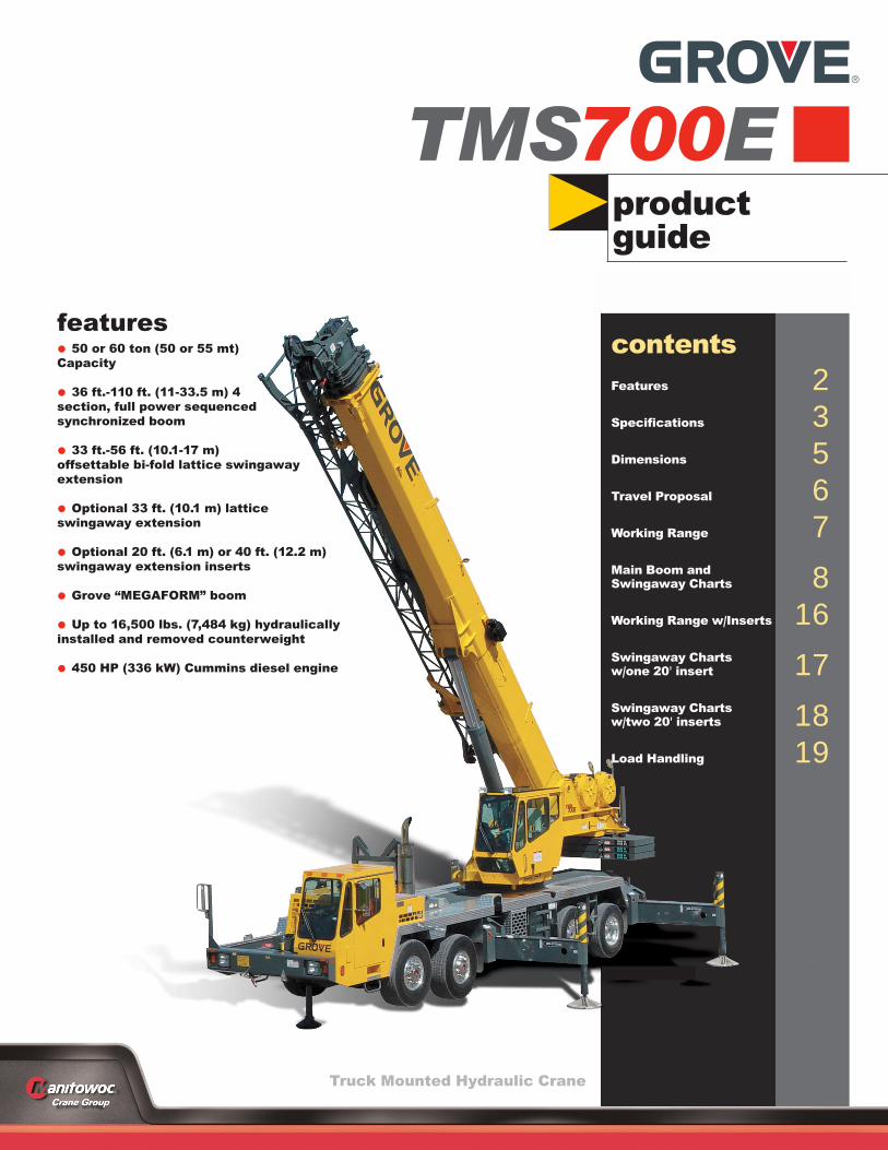
features• 50 or 60 ton (50 or 55 mt)Capacity
• 36 ft.-110 ft. (11-33.5 m) 4section, full power sequencedsynchronized boom
• 33 ft.-56 ft. (10.1-17 m)offsettable bi-fold lattice swingawayextension
• Optional 33 ft. (10.1 m) latticeswingaway extension
• Optional 20 ft. (6.1 m) or 40 ft. (12.2 m)swingaway extension inserts
• Grove “MEGAFORM” boom
• Up to 16,500 lbs. (7,484 kg) hydraulicallyinstalled and removed counterweight
• 450 HP (336 kW) Cummins diesel engine
TMS700E
Truck Mounted Hydraulic Crane
contentsFeatures 2Specifications 3Dimensions 5Travel Proposal 6Working Range 7Main Boom and Swingaway Charts 8Working Range w/Inserts 16Swingaway Chartsw/one 20' insert 17Swingaway Chartsw/two 20' inserts 18Load Handling 19

2
features
Optional 20 ft. (6.1 m) or 40 ft. (12.2 m)swingaway extension inserts offerexcellent capacities with an unprece-dented tip height of up to 212 ft.
Standard front & rear air ride suspensionprovides comfortable ride at max speed of65 mph (105 Km/h)
Cummins ISM 450 diesel carrier enginedelivers horsepower and torque neededto negotiate tough jobsites and achievehighway travel speeds
36 - 110 ft. (11 - 33.5 m) foursection full power sequencedsynchronized MEGAFORM™ boomdesigned for maximum vertical andlateral strength

3
specifications
TM
S700
E
Superstructure
Boom36 ft. - 110 ft. (11 m - 33.5 m) four section, full power sequencedsynchronized boom. Maximum Tip Height: 118 ft. (35.9 m).
Folding Lattice Extension33 ft. - 56 ft. (10.1 m - 17.1 m) folding lattice swingaway extensionoffsettable at 0 ˚, 25 ˚ or 45 ˚. Stows alongside base boom section.Maximum Tip Height: 172.5 ft. (52.6 m)
*Optional Lattice Extension33 ft. (10.1 m) lattice swingaway extension, offsettable at 0 ˚, 25 ˚ or45 ˚. Stows alongside base boom section.Maximum Tip Height: 148 ft. (45.1 m).
*Optional 20 ft. (6.1 m) or 40 ft. (12.2 m) SwingawayExtension Inserts
Installs between boom nose and extension, non-stowable.Maximum Tip Height: 192 ft. (58.5 m) - 20 ft. (6.1 m) insert
212 ft. (64.6 m) - 40 ft. (12.2 m) insert
Boom NoseQuick reeving type boom nose with 3 nylatron sheaves (4 for 60ton rating) mounted on heavy duty tapered roller bearings withremovable pin-type rope guards. Removable auxiliary boomnose with removable pin type rope guard.
Boom ElevationOne double acting hydraulic cylinder with integral holding valveprovides elevation from -3˚ to 78˚.
Load Moment & Anti-Two Block SystemStandard “Graphics Display” load moment and anti-two blocksystem with audio-visual warning and control lever lockout.These systems provide electronic display of boom angle, boomlength, radius, tip height, relative load moment, maximumpermissible load, load indication and warning of impending two-block condition. The standard “Work Area Definition System”allows the operator to pre-select and define safe working areas.If the crane approaches the pre-set limits, audio-visual warningsaid the operator in avoiding job-site obstructions.
CabHigh visibility, all steel cab with acoustical lining and tintedsafety glass throughout. Deluxe seat with armrest mountedhydraulic single axis controls. Dash panel incorporates gaugesfor all engine functions. Other standard features include: slidingside and rear windows, hot water heat, electric windshieldwash/wipe, circulating air fan, sliding skylight with sunscreenand electric skylight wiper, fire extinguisher, cup holder.
SwingPlanetary swing with foot applied multi-disc wet brake. Springapplied, hydraulically released parking brake. Two positionplunger type and 360 ˚ mechanical house locks operated fromcab.Maximum speed: 2.0 RPM.
Counterweight11,000 lbs. (4 990 kg) consisting of (2) 5,500 lb. (2 495 kg)sections. *Optional “Heavy Lift” package consisting of (1)additional 5,500 lb. (2 495 kg) section, for a total of 16,500 lb. (7484 kg). Hydraulic installation/removal.
Hydraulic SystemFour main gear pumps with a combined capacity of 135.4 GPM(513 L/m). Individual post pressure compensated valve banks.Maximum operating pressure: 4000 psi (27.6 Mpa). Return line type filter with full flow by-pass protection andservice indicator. Replaceable cartridge with beta rating of5/12/16. 170 gallons (643 L) reservoir. Remote mounted oil cooler withthermostatically controlled electric motor driven fan.
Hoist SpecificationsMain and Auxiliary Hoists-Model
HO3OG-16GPlanetary reduction with integral automatic brake, electronichoist drum rotation indicator, and hoist drum cable follower.Grooved drum.
Single Line Pull: 1st Layer: 18,134 lb. (8 226 kg)3rd Layer: 15,420 lb. (6 995 kg)5th Layer: 13,413 lb. (6 084 kg)
Maximum Single Line Speed: 580 FPM (177 m/min)
Maximum Permissible Line Pull: 16,800 lb. (7 620kg)w/standard 6 x 37 class rope
16,800 lb. (7 620 kg)w/optional 35 x 7 class rope
Rope Diameter: 3/4 in. (19 mm)
Rope Length: 500 ft. (152 m)
Rope Type: 6 x 36 WS non-rotationresistantOptional 35 x 7 rotationresistant
Maximum Rope Stowage: 695 ft. (212 m)
*Denotes optional equipment

4
specificationsT
MS700
E
Carrier
ChassisTriple box section, four-axle carrier, fabricated from highstrength,low alloy steel with towing and tie-down lugs.
Outrigger SystemFour hydraulic telescoping, single stage, double box beamoutriggers with inverted jack and integral holding valves.Quick release type steel outrigger floats 24 in. (610 mm)diameter. Three position setting with fully extended,intermediate (50%) extended and fully retractedcapacities.
Outrigger ControlsLocated in the superstructure cab and on the left side (umbilicaldesign), requires two hand operation. Crane level indicator (sightbubble) on right side console. *Optional controls in lighted boxes,mounted on both sides of chassis.
EngineCummins ISM 450 diesel, six cylinders, after cooled, 661 cu. in.(10.8 L), 450 bhp (336 kW) @ 1800 RPM. Maximum torque 1,450ft. lb. (1966 Nm) @ 1200 RPM. Equipped with enginebrake, engine block heater, cold start aid (less canister) and audio-visual engine distress system.
Fuel Tank Capacity100 gallons (379 L).
TransmissionRoadranger 11 speeds forward, 3 reverse.
DriveDrive 8 x 4 x 4.
SteeringFront axle, single circuit, mechanical steering withhydraulic assist.
AxlesFront: (2) beam-type steering axles, 83.3 in. (2.1 m) track.Rear: (2) single reduction drive axles, 75.1 in. (1.9 m)track. Inter-axle differential lock.
BrakesDual air, split system operating on all wheels. S-cam brakes on thefront and wedge brakes on the rear. Spring-applied, air releasedparking brake acting on rear axles. Air dryer.
SuspensionFront: Walking beam with air bags and shock absorbers.Rear: Walking beam with air bags and shock absorbers.
TiresFront: 445/65R 22.5 Goodyear G286, tubeless, mountedon aluminum disc wheels.Rear: 315/80R 22.5 Goodyear G286, tubeless, mountedon aluminum disc wheels.
*Optional TiresFront: 445/65R 22.5 Bridgestone M844F, tubeless.445/65R 22.5 Michelin XZY (WB), tubeless.Rear: 315/80R 22.5 Bridgestone M843, tubeless.315/80R 22.5 Michelin XZY-2 tubeless.
LightsFull lighting package including turn indicators, head, tail, brake,and hazard warning lights.
CabOne man design, all steel fabricated with acoustical lining andtinted safety glass throughout. Deluxe fabric covered, fullyadjustable air ride seat. Complete driving controls and engineinstrumentation including tilt telescope steering wheel, tachometer,speedometer, voltmeter, water temp., oil pressure, fuel level, airpressure gauge with A/V warning and engine high temp./low oilpressure A/V warning. Other standard items include hot waterheater/defroster, electric windshield wash/wipe, fire extinguisher,seat belt and door lock.
Electrical SystemTwo 12V, 2150 CCA maintenance free batteries. 12Vlighting/starting. Battery disconnect standard equipment.
Maximum Speed65 MPH (104 kph)
Gradeability (Theoretical)70%
Miscellaneous Standard EquipmentAluminum fenders with rear storage compartments; dual rear viewmirrors; electronic back-up alarm; pump disconnect; tire inflationkit; air cleaner restriction indicator; block and ball stowage; andchrome package which includes aluminum wheels.
*Optional Equipment*Flashing Light Package – includes amber strobe for both cabs*Trailing Boom Package – includes trailer air and electricaldisconnects and trailing boom kit with no spin differential (lessdolly)*Hookblocks*Air conditioning*Rear pintle hook*Aluminum outrigger pads*Cross axle differential locks*LMI calibration for on-rubber*LMI light bar*LMI data logger*Air horn
*Denotes optional equipment

5
dimensions
TM
S700
E
44' 5.75"(13557 mm)
35' 11" (10950 mm) RETRACTED110' 0" (33530 mm) EXTENDED
11' 9.18"(3586 mm)
5' 9.25"(1759 mm)
1' 7.52"(496 mm)
2' 1.00"(635 mm)
13' 2.00(4013 mm)
36' 6.87"(11147 mm)
5' 00"(1524 mm)
18' 6.00"(5639 mm)
8' 2.00"(2489 mm)
6' 10.92"(2106 mm)
19 DEGREES
10' 2.00"(3099 mm)
5' 0.00"(1524 mm)
15 DEGREES
10.00"(254 mm)
1' 9"(533 mm)
11.87(301 mm)
1' 9.83"(555 mm)
11' 5.12"(3483 mm)
13' 5.50"(4102 mm)
CLROTATION
8' 6.00"(2591 mm)
6' 9.84"(2079 mm)
FRONT TRACK
45' 1.00" (13741)STEERING RADIUS
13' 5.50" (4102 mm)TAILSWING
6' 2.45"(1891 mm)REAR TRACK
20' 00" (6096 mm)FULLY EXTENDED13' 11.78" (4262 mm)MID EXTENDED7' 11.62" (2429 mm)FULLY RETRACTED
Counterweight Configuration
Zero
5,500 lb. (2 495 kg)
11,000 lb. (4 990 kg)
16,500 lb. (7 485 kg)
1 2 3
Main Boom
33 ft. Swingaway
56 ft. Swingaway
76 ft. Boom extension(56 ft. + 20 ft. insert)
96 ft. Boom extension(56 ft. + 40 ft. insert)
� 16,500 lb.� 11,000 lb.� 5,500 lb.� 0 lb.
Outrigger Span� 20 ft. =� 14 ft. =� 8 ft. =Rubber� P&C =
Load Chart Configuration – 360o
5,500 lb.
5,500 lb.
5,500 lb.
1.
2.
3.

Basic machine including 110 ft. (33.5 m) main boom,main and auxiliary hoists with cable, driver and no counterweight. 74,712 (33 889) 37,097 (16 827) 37,615 (17 062)Additions:5,500 lb. (2 495 kg.) counterweight pinned on superstructure 5,500 (2 495) -2,214 (1 004) 7,714 (3 499)11,000 lb. (4 990 kg.) counterweight pinned on superstructure 11,000 (4 990) -4,428 (2 009) 15,428 (6 998)16,500 lb. (7 485 kg.) counterweight pinned on superstructure 16,500 (7 484) -6,642 (3 013) 23,142 (10 497)5,500 lb. (2 495 kg.) counterweight stowed on carrier deck 5,500 (2 495) 4,692 (2 128) 808 (367)11,000 lb. (4 990 kg.) counterweight stowed on carrier deck 11,000 (4 990) 9,384 (4 257) 1,616 (733)Swingaway carrier brackets 330 (150) 282 (128) 48 (22)33 ft. (10.1 m) swingaway 1,730 (785) 1,972 (895) -242 (-110)33 - 56 ft. (10.1 - 17.1 m) swingaway 2,480 (1 125) 2,502 (1 135) -22 (-10)Auxiliary boom nose 130 (59) 251 (114) -121 (-55)40 ton (35 mt) hookblock stowed in trough 800 (363) 1,142 (518) -342 (-155)50 ton (45 mt) hookblock stowed in troug 1,000 (454) 1,428 (648) -428 (-194)60 ton (55 mt) hookblock stowed in trough (567) 1,785 (810) -535 (-243)8.3 ton (7.5 mt) headache ball stowed in trough 371 (168) 530 (240) -159 (-72)Air conditioning superstructure cab 285 (129) 10 (5) 275 (125)Air conditioning chassis cab 88 (40) 115 (52) -27 (-12)
h1,250
6
TM
S700
Etravel proposals
Sub titleBoom over front
5'
(1 524)
5'
(1 524)
18.5'
(5639)
Basic machine including 110 ft. (33.5 m) main boom, main and auxiliary hoists with cable, driver, no counterweight and 6,000 lb. (2 722 kg.) tandem axle dolly. 80,737 (36 622) 33,479 (15 186) 29,275 (13 279) 17,983 (8 157)
Additions:5,500 lb. (2 495 kg.) counterweight stowed on carrier deck. 5,500 (2 495) 4,692 (2 128) 808 (367) 0 (0)
11,000 lb. (4 990 kg.) counterweight stowed on carrier deck. 11,000 (4 990) 9,384 (4 257) 1,616 (733) 0 (0)33 ft. (10.1 m) swingaway with brackets. 2,060 (934) 281 (128) 239 (108) 1,540 (699)33 - 56 ft. (10.1 - 17.1 m) swingaway with brackets. 2,810 (1 275) 384 (174) 326 (148) 2,100 (953)Auxiliary boom nose. 130 (59) -24 (-11) -20 (-9) 174 (79)40 ton (35 mt) hookblock hanging at boom nose. 800 (363) -126 (-57) -107 (-49) 1,033 (469)
50 ton (45 mt) hookblock hanging at boom 1,000 (454) -157 (-71) -134 (-61) 1,291 (586)60 ton (55 mt) hookblock hanging at boom nose. 1,250 (567) -197 (-89) -167 (-76) 1,614 (732)
8.3 ton (7.5 mt) headache ball hanging at boom nose. 371 (168) -58 (-26) -50 (-23) 479 (217)
nose.
57.6'
(17 556)
5'
(1524)
5'
(1524)
4.5'
(1372)
18.5'
(5639)13'
(3962)
Unit Configuration lb. (kg) Gross Front Rear
Trailing boom dolly
Unit Configuration lb. (kg.) Gross Front Rear Dolly

7
working range
THIS CHART IS ONLY A GUIDE AND SHOULD NOT BE USED TO OPERATE THE CRANE. The individual crane’s load chart,operating instructions and other instructional plates must be read and understood prior to operating the crane.
TM
S700
EOPERATING RADIUS IN FEET FROM AXIS OF ROTATION
(BOOM DEFLECTION NOT SHOWN)
HE
IGH
T F
RO
M G
RO
UN
D IN
FE
ET
BO
OM
LE
NG
TH
AN
D E
XT
EN
SIO
N IN
FE
ET
78o
MAX.BOOMANGLE
AXIS OFROTATION
180
170
160
150
140
130
120
110
100
90
80
70
60
50
40
30
20
10
0160 140 120 100 80 60 40 20150 130 110 90 70 50 30 10 0
56' EXT
33' EXT
110
100
90
80
70
60
50
40
36
0o�
10o �
20o �
30o �
40o �
50o �
60o �
70o �
8'-2-3/4" 8'-6-3/4"Dimensions are for largest Grove furnished hook block and headache ball, with anti-two block activated.
36-110' main boom + 33-56' lattice extension

36 - 110 ft. 16,500 lbs. 100%20' 0"
Over Rear
Main Boom Length in FeetFeet
#0001
35 40 50 **60 70 80 90 100 110
10 120,000(69)
84,400(72)
80,200(76)
*62,500(78)
12 100,000(65.5)
84,400(68.5)
80,200(73.5)
62,500(77)
*36,800(78)
15 87,300(59.5)
82,700(63.5)
80,200(70)
61,000(74)
36,800(76.5)
*36,800(78)
*31,000(78)
20 68,250(49)
65,000(55)
64,300(63.5)
50,650(69)
36,800(72)
36,800(75)
31,000(77)
*29,100(78)
*24,000(78)
25 55,650(36)
53,100(45)
52,000(56.5)
41,800(63.5)
36,800(68)
34,000(71)
30,000(73.5)
27,000(76)
24,000(77.5)
30 44,100(31.5)
39,600(48.5)
38,000(57.5)
33,400(63)
29,000(67)
25,300(70.5)
24,200(72.5)
22,000(75)
35 32,400(40)
29,750(51.5)
28,700(58)
25,000(63)
22,200(67)
21,750(69.5)
20,000(72)
40 26,050(28)
25,500(45)
23,600(53)
22,000(59)
20,200(63)
19,000(66.5)
18,500(69)
45 20,000(37)
19,700(47.5)
18,800(54.5)
17,800(59.5)
17,300(63)
17,300(66.5)
50 17,850(26.5)
16,800(41)
16,500(49.5)
16,000(55.5)
16,000(60)
16,000(63.5)
55 14,900(33.5)
14,650(44.5)
14,100(51)
14,100(56.5)
14,100(60)
60 13,050(24)
12,800(38.5)
12,200(47)
12,200(52.5)
12,200(57)
65 11,450(31.5)
10,800(42)
10,600(48.5)
10,600(53.5)
70 10,100(22.5)
9,450(36.5)
9,000(44.5)
9,000(50)
75 8,290(30)
7,800(40)
7,800(46.5)
80 7,140(21.5)
6,600(34.5)
6,600(42.5)
85 5,800(28.5)
5,800(38)
90 5,000(20.5)
5,000(33)
95 4,440(27.5)
100 3,880(19.5)
Minimum boom angle (deg.) for indicated length (no load) 0
Maximum boom length (ft.) at 0 degree boom angle (no load) 110
NOTE: ( ) Boom angles are in degrees.#LMI operating code. Refer to LMI manual for instructions.*This capacity is based on maximum boom angle.
Lifting Capacities at Zero Degree Boom Angle
BoomAngle
Main Boom Length in Feet
35 40 50 **60 70 80 90 100 110
0o 29,050(29.8)
24,450(34.2)
17,050(44.2)
11,950(54.6)
9,640(64.2)
7,810(74.2)
6,390(84.2)
4,770(94.2)
3,350(104.2)
NOTE: ( ) Reference radii in feet. A6-829-101319
**60 ft. boom length is with inner-mid extended and outer-mid & fly retracted.
#0001
36 - 110 ft. 16,500 lbs. 100%20' 0"
360º
Main Boom Length in FeetFeet 35 40 50 **60 70 80 90 100 110
10 120,000(69)
84,400(72)
80,200(76)
*62,500(78)
12 100,000(65.5)
84,400(68.5)
80,200(73.5)
62,500(77)
*36,800(78)
15 87,300(59.5)
82,700(63.5)
80,200(70)
61,000(74)
36,800(76.5)
*36,800(78)
*31,000
*29,100(78)
20 68,250(49)
65,000(55)
64,300(63.5)
50,650(69)
36,800(72)
36,800(75)
31,000(77) (78)
*24,000(78)
25 54,900(36)
53,100(45)
52,000(56.5)
41,800(63.5)
36,800(68)
34,000(71)
30,000(73.5)
27,000(76)
24,000(77.5)
30 39,350(31.5)
38,700(48.5)
37,850(57.5)
33,400(63)
29,000(67)
25,300(70.5)
24,200(72.5)
22,000(75)
35 29,400(40)
28,400(51.5)
28,700(58)
25,000(63)
22,200(67)
21,750(69.5)
20,000(72)
40 23,050(28)
22,100(45)
22,750(53)
22,000(59)
20,200(63)
19,000(66.5)
18,500(69)
45 17,550(37)
18,250(47.5)
18,800(54.5)
17,800(59.5)
17,300(63)
17,300(66.5)
50 14,050(26.5)
14,850(41)
15,600(49.5)
16,000(55.5)
16,000(60)
16,000(63.5)
55 12,200(33.5)
12,950(44.5)
13,650(51)
14,100(56.5)
14,100(60)
60 10,050(24)
10,850(38.5)
11,600(47)
12,000(52.5)
12,200(57)
65 9,110(31.5)
9,900(42)
10,250(48.5)
10,600(53.5)
70 7,650(22.5)
8,450(36.5)
8,820(44.5)
9,000(50)
75 7,210(30)
7,580(40)
7,800(46.5)
80 6,150(21.5)
6,490(34.5)
6,600(42.5)
85 5,550(28.5)
5,800(38)
90 4,730(20.5)
5,000(33)
95 4,270(27.5)
100 3,600(19.5)
Minimum boom angle (deg.) for indicated length (no load) 0
Maximum boom length (ft.) at 0 degree boom angle (no load) 110
NOTE: ( ) Boom angles are in degrees.#LMI operating code. Refer to LMI manual for instructions.*This capacity is based on maximum boom angle.
Lifting Capacities at Zero Degree Boom Angle
BoomAngle
Main Boom Length in Feet
35 40 50 **60 70 80 90 100 110
0o 29,050(29.8)
24,450(34.2)
17,050(44.2)
11,600(54.6)
8,570(64.2)
6,610(74.2)
5,380(84.2)
4,120(94.2)
3,110(104.2)
NOTE: ( ) Reference radii in feet. A6-829-101318
**60 ft. boom length is with inner-mid extended and outer-mid & fly retracted.
8
load charts
THIS CHART IS ONLY A GUIDE AND SHOULD NOT BE USED TO OPERATE THE CRANE. The individual crane’s load chart,operating instructions and other instructional plates must be read and understood prior to operating the crane.
TM
S700
E

9
load charts
THIS CHART IS ONLY A GUIDE AND SHOULD NOT BE USED TO OPERATE THE CRANE. The individual crane’s load chart,operating instructions and other instructional plates must be read and understood prior to operating the crane.
TM
S700
E
Pounds
Feet
33 ft. LENGTH 56 ft. LENGTH#0021 #0022 #0023 #0041 #0042 #0043
0o
OFFSET25o
OFFSET45o
OFFSET0o
OFFSET25o
OFFSET45o
OFFSET
30 12,900(78)
35 12,900(76)
*8,330(78)
40 12,900(74)
*10,850(78)
8,330(77.5)
45 12,900(72)
10,450(77)
*7,410(78)
8,330(76)
50 12,100(70)
10,000(74.5)
7,200(77.5)
8,330(74.5)
55 11,100(68)
9,220(72.5)
6,990(75)
8,250(73)
*5,300(78)
60 10,100(66)
8,550(70.5)
6,800(72.5)
7,540(71)
5,140(77)
65 9,130(63.5)
7,930(68)
6,650(70.5)
7,160(69)
5,100(75)
*3,860(78)
70 8,460(61.5)
7,380(65.5)
6,490(68)
6,820(67.5)
5,100(73)
3,790(77.5)
75 7,840(59)
6,900(63)
6,370(65.5)
6,300(65.5)
4,800(71)
3,660(75)
80 7,230(56.5)
6,470(60.5)
6,110(62.5)
5,810(63.5)
4,580(69)
3,550(73)
85 6,470(54)
6,070(58)
5,780(60)
5,370(61.5)
4,470(67.5)
3,450(71)
90 5,670(51)
5,720(55.5)
5,480(57)
4,980(59.5)
4,330(65.5)
3,410(68.5)
95 4,970(48.5)
5,400(52.5)
5,200(54)
4,630(57)
4,070(63)
3,300(66.5)
100 4,350(45.5)
4,840(49.5)
4,950(51)
4,320(55)
3,830(61)
3,260(64)
105 3,790(42.5)
4,210(46.5)
4,470(47.5)
4,040(52.5)
3,620(58.5)
3,220(62)
110 3,290(39.5)
3,640(43)
3,760(50.5)
3,410(56)
3,180(59.5)
115 2,830(36)
3,130(39.5)
3,290(48)
3,230(53.5)
3,060(56.5)
120 2,420(32)
2,660(35)
2,860(45.5)
3,050(51)
2,940(53.5)
125 2,040(27.5)
2,240(30.5)
2,470(42.5)
2,890(48.5)
2,800(50.5)
130 1,700(22)
2,120(39.5)
2,590(45.5)
135 1,790(36.5)
2,200(42.5)
140 1,480(33)
1,840(38.5)
145 1,200(29.5)
1,500(34.5)
No Load Stability DataMin. boomangle forindicated
length21o 25o 45o 28o 28o 45o
Max. boomlength at 0o
boom angle100 ft. 90 ft.
NOTE: ( ) Boom angles are in degrees. A6-829-101337
*This capacity is based upon maximum boom angle.
#LMI operating code. Refer to LMI manual for instructions.
36 - 110 ft. 16,500 lbs. 100%20' 0"
360º33 - 56 ft.
NOTES:1. All capacities above the bold line are based on
structural strength of boom extension.2. 33 ft. and 56 ft. boom extension lengths may be
used for single line lifting service.3. Radii listed are for a fully extended boom with the
boom extension erected. For main boom lengthsless than fully extended, the rated loads aredetermined by boom angle. Use only the columnwhich corresponds to the boom extension lengthand offset for which the machine is configured. Forboom angles not shown, use the rating of the nextlower boom angle.
4. WARNING: Operation of this machine with heavierloads than the capacities listed is strictly prohibited.Machine tipping with boom extension occursrapidly and without advance warning.
5. Boom angle is the angle above or below horizontalof the longitudinal axis of the boom base sectionafter lifting rated load.
6. Capacities listed are with outriggers properlyextended and vertical jacks set only.

10
load charts
THIS CHART IS ONLY A GUIDE AND SHOULD NOT BE USED TO OPERATE THE CRANE. The individual crane’s load chart,operating instructions and other instructional plates must be read and understood prior to operating the crane.
TM
S700
E
36 - 110 ft. 11,000 lbs. 100%20' 0"
OverRear
Main Boom Length in FeetFeet
#0101
35 40 50 **60 70 80 90 100 110
10 120,000(69)
84,400(72)
80,200(76)
*62,500(78)
12 100,000(65.5)
84,400(68.5)
80,200(73.5)
62,500(77)
*36,800(78)
15 87,300(59.5)
82,700(63.5)
80,200(70)
61,000(74)
36,800(76.5)
*36,800(78)
*31,000(78)
20 68,250(49)
65,000(55)
64,300(63.5)
50,650(69)
36,800(72)
36,800(75)
31,000(77)
*29,100(78)
*24,000(78)
25 52,900(36)
52,700(45)
52,000(56.5)
41,800(63.5)
36,800(68)
34,000(71)
30,000(73.5)
27,000(76)
24,000(77.5)
30 41,750(31.5)
39,600(48.5)
38,000(57.5)
33,400(63)
29,000(67)
25,300(70.5)
24,200(72.5)
22,000(75)
35 32,400(40)
29,750(51.5)
28,700(58)
25,000(63)
22,200(67)
21,750(69.5)
20,000(72)
40 26,050(28)
25,500(45)
23,600(53)
22,000(59)
20,200(63)
19,000(66.5)
18,500(69)
45 20,000(37)
19,700(47.5)
18,800(54.5)
17,800(59.5)
17,300(63)
17,300(66.5)
50 16,650(26.5)
16,800(41)
16,500(49.5)
16,000(55.5)
16,000(60)
16,000(63.5)
55 14,500(33.5)
14,650(44.5)
14,100(51)
14,100(56.5)
14,100(60)
60 12,100(24)
12,800(38.5)
12,200(47)
12,200(52.5)
12,200(57)
65 10,950(31.5)
10,800(42)
10,600(48.5)
10,600(53.5)
70 9,290(22.5)
9,450(36.5)
9,000(44.5)
9,000(50)
75 8,290(30)
7,800(40)
7,800(46.5)
80 7,140(21.5)
6,600(34.5)
6,600(42.5)
85 5,800(28.5)
5,800(38)
90 5,000(20.5)
5,000(33)
95 4,440(27.5)
100 3,880(19.5)
Minimum boom angle (deg.) for indicated length (no load) 0
Maximum boom length (ft.) at 0 degree boom angle (no load) 110
NOTE: ( ) Boom angles are in degrees.#LMI operating code. Refer to LMI manual for instructions.*This capacity is based on maximum boom angle.
Lifting Capacities at Zero Degree Boom Angle
BoomAngle
Main Boom Length in Feet
35 40 50 **60 70 80 90 100 110
0o 29,050(29.8)
24,450(34.2)
17,050(44.2)
11,950(54.6)
9,640(64.2)
7,810(74.2)
6,390(84.2)
4,770(94.2)
3,350(104.2)
NOTE: ( ) Reference radii in feet. A6-829-101321
**60 ft. boom length is with inner-mid extended and outer-mid & fly retracted.
36 - 110 ft. 11,000 lbs. 100%20' 0"
360º
Main Boom Length in FeetFeet
#0101
35 40 50 **60 70 80 90 100 110
10 120,000(69)
84,400(72)
80,200(76)
*62,500(78)
12 100,000(65.5)
84,400(68.5)
80,200(73.5)
62,500(77)
*36,800(78)
15 87,300(59.5)
82,700(63.5)
80,200(70)
61,000(74)
36,800(76.5)
*36,800(78)
*31,000(78)
20 68,250(49)
65,000(55)
64,300(63.5)
50,650(69)
36,800(72)
36,800(75)
31,000(77)
*29,100(78)
*24,000(78)
25 48,550(36)
48,350(45)
47,650(56.5)
41,800(63.5)
36,800(68)
34,000(71)
30,000(73.5)
27,000(76)
24,000(77.5)
30 34,300(31.5)
33,650(48.5)
32,800(57.5)
33,400(63)
29,000(67)
25,300(70.5)
24,200(72.5)
22,000(75)
35 25,250(40)
24,350(51.5)
25,000(58)
25,000(63)
22,200(67)
21,750(69.5)
20,000(72)
40 19,500(28)
18,700(45)
19,350(53)
20,050(59)
20,200(63)
19,000(66.5)
18,500(69)
45 14,650(37)
15,350(47.5)
16,050(54.5)
16,750(59.5)
17,300(63)
17,300(66.5)
50 11,550(26.5)
12,350(41)
13,050(49.5)
13,750(55.5)
14,300(60)
14,850(63.5)
55 9,960(33.5)
10,700(44.5)
11,450(51)
11,900(56.5)
12,400(60)
60 8,040(24)
8,850(38.5)
9,590(47)
10,000(52.5)
10,400(57)
65 7,280(31.5)
8,070(42)
8,450(48.5)
8,830(53.5)
70 5,970(22.5)
6,760(36.5)
7,140(44.5)
7,480(50)
75 5,660(30)
6,020(40)
6,350(46.5)
80 4,710(21.5)
5,050(34.5)
5,370(42.5)
85 4,200(28.5)
4,510(38)
90 3,460(20.5)
3,750(33)
95 3,080(27.5)
100 2,480(19.5)
Minimum boom angle (deg.) for indicated length (no load) 0
Maximum boom length (ft.) at 0 degree boom angle (no load) 110
NOTE: ( ) Boom angles are in degrees.#LMI operating code. Refer to LMI manual for instructions.*This capacity is based on maximum boom angle.
Lifting Capacities at Zero Degree Boom Angle
BoomAngle
Main Boom Length in Feet
35 40 50 **60 70 80 90 100 110
0o 29,050(29.8)
24,450(34.2)
16,000(44.2)
9,340(54.6)
6,710(64.2)
5,030(74.2)
4,020(84.2)
2,920(94.2)
2,030(104.2)
NOTE: ( ) Reference radii in feet. A6-829-101320
**60 ft. boom length is with inner-mid extended and outer-mid & fly retracted.

11
load charts
THIS CHART IS ONLY A GUIDE AND SHOULD NOT BE USED TO OPERATE THE CRANE. The individual crane’s load chart,operating instructions and other instructional plates must be read and understood prior to operating the crane.
TM
S700
E
Pounds
Min. boomangle forindicated
length25o 25o 45o 33o 36o 45o
36 - 110 ft. 11,000 lbs. 100%20' 0"
360º33 - 56 ft.
Feet
33 ft. LENGTH 56 ft. LENGTH
#0121 #0122 #0123 #0141 #0142 #01430o
OFFSET25o
OFFSET45o
OFFSET0o
OFFSET25o
OFFSET45o
OFFSET
30 12,900(78)
35 12,900(76)
*8,330(78)
40 12,900(74)
*10,850(78)
8,330(77.5)
45 12,900(72)
10,450(77)
*7,410(78)
8,330(76)
50 12,100(70)
10,000(74.5)
7,200(77.5)
8,330(74.5)
55 11,100(68)
9,220(72.5)
6,990(75)
8,250(73)
*5,300(78)
60 10,100(66)
8,550(70.5)
6,800(72.5)
7,540(71)
5,140(77)
65 9,130(63.5)
7,930(68)
6,650(70.5)
7,160(69)
5,100(75)
*3,860(78)
70 7,960(61.5)
7,380(65.5)
6,490(68)
6,820(67.5)
5,100(73)
3,790(77.5)
75 6,870(59)
6,900(63)
6,370(65.5)
6,300(65.5)
4,800(71)
3,660(75)
80 5,930(56.5)
6,470(60.5)
6,110(62.5)
5,810(63.5)
4,580(69)
3,550(73)
85 5,120(54)
5,880(58)
5,780(60)
5,370(61.5)
4,470(67.5)
3,450(71)
90 4,410(51)
5,070(55.5)
5,440(57)
4,960(59.5)
4,330(65.5)
3,410(68.5)
95 3,780(48.5)
4,350(52.5)
4,680(54)
4,310(57)
4,070(63)
3,300(66.5)
100 3,230(45.5)
3,710(49.5)
4,010(51)
3,730(55)
3,830(61)
3,260(64)
105 2,730(42.5)
3,140(46.5)
3,410(47.5)
3,210(52.5)
3,620(58.5)
3,220(62)
110 2,280(39.5)
2,630(43)
2,750(50.5)
3,410(56)
3,180(59.5)
115 1,870(36)
2,170(39.5)
2,330(48)
3,020(53.5)
3,060(56.5)
120 1,500(32)
1,750(35)
1,940(45.5)
2,550(51)
2,800(53.5)
125 1,170(27.5)
1,360(30.5)
1,590(42.5)
2,130(48.5)
2,330(50.5)
130 1,270(39.5)
1,740(45.5)
135 1,390(42.5)
140 1,060(38.5)
Max. boomlength at 0o
boom angle90 ft. 80 ft.
NOTE: ( ) Boom angles are in degrees. A6-829-101338
*This capacity is based upon maximum boom angle.#LMI operating code. Refer to LMI manual for instructions.
No Load Stability Data
NOTES:1. All capacities above the bold line are based on
structural strength of boom extension.2. 33 ft. and 56 ft. boom extension lengths may be
used for single line lifting service.3. Radii listed are for a fully extended boom with the
boom extension erected. For main boom lengthsless than fully extended, the rated loads aredetermined by boom angle. Use only the columnwhich corresponds to the boom extension lengthand offset for which the machine is configured. Forboom angles not shown, use the rating of the nextlower boom angle.
4. WARNING: Operation of this machine with heavierloads than the capacities listed is strictly prohibited.Machine tipping with boom extension occursrapidly and without advance warning.
5. Boom angle is the angle above or below horizontalof the longitudinal axis of the boom base sectionafter lifting rated load.
6. Capacities listed are with outriggers properlyextended and vertical jacks set only.

12
load charts
THIS CHART IS ONLY A GUIDE AND SHOULD NOT BE USED TO OPERATE THE CRANE. The individual crane’s load chart,operating instructions and other instructional plates must be read and understood prior to operating the crane.
TM
S700
E
36 - 110 ft. 5,500 lbs. 100%20' 0"
360o
Main Boom Length in FeetFeet
#0201
35 40 50 **60 70 80 90 100 110
10 118,500(69)
84,400(72)
80,200(76)
*62,500(78)
12 100,000(65.5)
84,400(68.5)
80,200(73.5)
62,500(77)
*36,800(78)
15 87,300(59.5)
82,700(63.5)
80,200(70)
61,000(74)
36,800(76.5)
*36,800(78)
*31,000(78)
20 66,000(49)
65,000(55)
64,300(63.5)
50,650(69)
36,800(72)
36,800(75)
31,000(77)
*29,100(78)
*24,000(78)
25 41,100(36)
41,000(45)
40,600(56.5)
40,150(63.5)
36,800(68)
34,000(71)
30,000(73.5)
27,000(76)
24,000(77.5)
30 28,400(31.5)
28,150(48.5)
27,750(57.5)
28,450(63)
29,000(67)
25,300(70.5)
24,200(72.5)
22,000(75)
35 20,700(40)
20,300(51.5)
21,000(58)
21,750(63)
22,200(67)
21,750(69.5)
20,000(72)
40 15,600(28)
15,350(45)
16,050(53)
16,750(59)
17,500(63)
17,900(66.5)
18,300(69)
45 11,750(37)
12,500(47.5)
13,200(54.5)
13,950(59.5)
14,300(63)
14,700(66.5)
50 9,040(26.5)
9,850(41)
10,550(49.5)
11,250(55.5)
11,650(60)
12,000(63.5)
55 7,720(33.5)
8,500(44.5)
9,210(51)
9,570(56.5)
9,940(60)
60 6,010(24)
6,810(38.5)
7,550(47)
7,900(52.5)
8,260(57)
65 5,410(31.5)
6,190(42)
6,540(48.5)
6,880(53.5)
70 4,250(22.5)
5,020(36.5)
5,400(44.5)
5,740(50)
75 4,030(30)
4,420(40)
4,770(46.5)
80 3,190(21.5)
3,570(34.5)
3,940(42.5)
85 2,830(28.5)
3,200(38)
90 2,180(20.5)
2,550(33)
95 1,980(27.5)
100 1,470(19.5)
Minimum boom angle (deg.) for indicated length (no load) 0
Maximum boom length (ft.) at 0 degree boom angle (no load) 110
NOTE: ( ) Boom angles are in degrees.#LMI operating code. Refer to LMI manual for instructions.*This capacity is based on maximum boom angle.
Lifting Capacities at Zero Degree Boom Angle
BoomAngle
Main Boom Length in Feet
35 40 50 **60 70 80 90 100 110
0o 28,850(29.8)
21,800(34.2)
12,500(44.2)
7,080(54.6)
4,830(64.2)
3,410(74.2)
2,570(84.2)
1,710(94.2)
1,080(104.2)
NOTE: ( ) Reference radii in feet. A6-829-101322
**60 ft. boom length is with inner-mid extended and outer-mid & fly retracted.
36 - 110 ft. 5,500 lbs. 100%20' 0"
OverRear
Main Boom Length in FeetFeet
#0201
35 40 50 **60 70 80 90 100 110
10 120,000(69)
84,400(72)
80,200(76)
*62,500(78)
12 100,000(65.5)
84,400(68.5)
80,200(73.5)
62,500(77)
*36,800(78)
15 87,300(59.5)
82,700(63.5)
80,200(70)
61,000(74)
36,800(76.5)
*36,800(78)
*31,000(78)
20 66,000(49)
65,000(55)
64,300(63.5)
50,650(69)
36,800(72)
36,800(75)
31,000(77)
*29,100(78)
*24,000(78)
25 50,050(36)
49,850(45)
49,500(56.5)
41,800(63.5)
36,800(68)
34,000(71)
30,000(73.5)
27,000(76)
24,000(77.5)
30 38,100(31.5)
38,200(48.5)
38,000(57.5)
33,400(63)
29,000(67)
25,300(70.5)
24,200(72.5)
22,000(75)
35 28,700(40)
28,600(51.5)
28,700(58)
25,000(63)
22,200(67)
21,750(69.5)
20,000(72)
40 22,200(28)
22,200(45)
23,000(53)
22,000(59)
20,200(63)
19,000(66.5)
18,500(69)
45 17,600(37)
18,400(47.5)
18,800(54.5)
17,800(59.5)
17,300(63)
17,300(66.5)
50 14,100(26.5)
14,950(41)
15,750(49.5)
16,000(55.5)
16,000(60)
16,000(63.5)
55 12,250(33.5)
13,050(44.5)
13,800(51)
14,100(56.5)
14,100(60)
60 10,050(24)
10,900(38.5)
11,650(47)
12,000(52.5)
12,200(57)
65 9,100(31.5)
9,890(42)
10,200(48.5)
10,550(53.5)
70 7,590(22.5)
8,380(36.5)
8,740(44.5)
9,000(50)
75 7,100(30)
7,480(40)
7,800(46.5)
80 5,990(21.5)
6,370(34.5)
6,600(42.5)
85 5,410(28.5)
5,770(38)
90 4,570(20.5)
4,920(33)
95 4,180(27.5)
100 3,520(19.5)
Minimum boom angle (deg.) for indicated length (no load) 0
Maximum boom length (ft.) at 0 degree boom angle (no load) 110
NOTE: ( ) Boom angles are in degrees.#LMI operating code. Refer to LMI manual for instructions.*This capacity is based on maximum boom angle.
Lifting Capacities at Zero Degree Boom Angle
BoomAngle
Main Boom Length in Feet
35 40 50 **60 70 80 90 100 110
0o 29,050(29.8)
24,450(34.2)
17,050(44.2)
11,600(54.6)
8,550(64.2)
6,520(74.2)
5,190(84.2)
3,950(94.2)
3,020(104.2)
NOTE: ( ) Reference radii in feet. A6-829-101323
**60 ft. boom length is with inner-mid extended and outer-mid & fly retracted.

13
load charts
THIS CHART IS ONLY A GUIDE AND SHOULD NOT BE USED TO OPERATE THE CRANE. The individual crane’s load chart,operating instructions and other instructional plates must be read and understood prior to operating the crane.
TM
S700
E
Pounds
36 - 110 ft. 5,500 lbs. 100%20' 0"
360º33 - 56 ft.
Feet
33 ft. LENGTH 56 ft. LENGTH
#0221 #0222 #0223 #0241 #0242 #02430o
OFFSET25o
OFFSET45o
OFFSET0o
OFFSET25o
OFFSET45o
OFFSET
30 12,900(78)
35 12,900(76)
*8,330(78)
40 12,900(74)
*10,850(78)
8,330(77.5)
45 12,900(72)
10,450(77)
*7,410(78)
8,330(76)
50 12,100(70)
10,000(74.5)
7,200(77.5)
8,330(74.5)
55 10,450(68)
9,220(72.5)
6,990(75)
8,250(73)
*5,300(78)
60 8,780(66)
8,550(70.5)
6,800(72.5)
7,540(71)
5,140(77)
65 7,420(63.5)
7,930(68)
6,650(70.5)
7,160(69)
5,100(75)
*3,860(78)
70 6,280(61.5)
7,260(65.5)
6,490(68)
6,820(67.5)
5,100(73)
3,790(77.5)
75 5,310(59)
6,180(63)
6,370(65.5)
6,030(65.5)
4,800(71)
3,660(75)
80 4,490(56.5)
5,250(60.5)
5,840(62.5)
5,150(63.5)
4,580(69)
3,550(73)
85 3,770(54)
4,450(58)
4,950(60)
4,400(61.5)
4,470(67.5)
3,450(71)
90 3,150(51)
3,750(55.5)
4,180(57)
3,730(59.5)
4,330(65.5)
3,410(68.5)
95 2,590(48.5)
3,130(52.5)
3,490(54)
3,140(57)
4,070(63)
3,300(66.5)
100 2,100(45.5)
2,580(49.5)
2,890(51)
2,620(55)
3,590(61)
3,260(64)
105 1,660(42.5)
2,080(46.5)
2,340(47.5)
2,160(52.5)
3,030(58.5)
3,220(62)
110 1,270(39.5)
1,640(43)
1,740(50.5)
2,520(56)
2,880(59.5)
115 1,240(39.5)
1,360(48)
2,050(53.5)
2,360(56.5)
120 1,010(45.5)
1,640(51)
1,890(53.5)
125 1,250(48.5)
1,450(50.5)
Min. boomangle forindicated
length37o 37o 45o 45o 46o 48o
Max. boomlength at 0o
boom angle80 ft. 60 ft.
NOTE: ( ) Boom angles are in degrees. A6-829-101339
*This capacity is based upon maximum boom angle.
#LMI operating code. Refer to LMI manual for instructions.
No Load Stability Data
NOTES:1. All capacities above the bold line are based on
structural strength of boom extension.2. 33 ft. and 56 ft. boom extension lengths may be
used for single line lifting service.3. Radii listed are for a fully extended boom with the
boom extension erected. For main boom lengthsless than fully extended, the rated loads aredetermined by boom angle. Use only the columnwhich corresponds to the boom extension lengthand offset for which the machine is configured. Forboom angles not shown, use the rating of the nextlower boom angle.
4. WARNING: Operation of this machine with heavierloads than the capacities listed is strictly prohibited.Machine tipping with boom extension occursrapidly and without advance warning.
5. Boom angle is the angle above or below horizontalof the longitudinal axis of the boom base sectionafter lifting rated load.
6. Capacities listed are with outriggers properlyextended and vertical jacks set only.

14
load charts
THIS CHART IS ONLY A GUIDE AND SHOULD NOT BE USED TO OPERATE THE CRANE. The individual crane’s load chart,operating instructions and other instructional plates must be read and understood prior to operating the crane.
TM
S700
E
36 - 110 ft. 100%20' 0"
0 lbs. 360º
Main Boom Length in FeetFeet
#0801
35 40 50 **60 70 80 90 100 110
10 117,500(69)
84,400(72)
80,200(76)
*62,500(78)
12 100,000(65.5)
84,400(68.5)
80,200(73.5)
62,500(77)
*36,800(78)
15 87,300(59.5)
82,700(63.5)
80,200(70)
61,000(74)
36,800(76.5)
*36,800(78)
*31,000(78)
20 56,000(49)
55,750(55)
55,300(63.5)
50,650(69)
36,800(72)
36,800(75)
31,000(77)
*29,100(78)
*24,000(78)
25 34,350(36)
34,300(45)
33,850(56.5)
33,400(63.5)
34,100(68)
34,000(71)
30,000(73.5)
27,000(76)
24,000(77.5)
30 23,350(31.5)
23,100(48.5)
22,700(57.5)
23,400(63)
24,150(67)
24,850(70.5)
24,200(72.5)
22,000(75)
35 16,650(40)
16,250(51.5)
16,950(58)
17,700(63)
18,400(67)
18,850(69.5)
19,300(72)
40 12,250(28)
12,000(45)
12,650(53)
13,400(59)
14,100(63)
14,550(66.5)
14,950(69)
45 8,890(37)
9,620(47.5)
10,300(54.5)
11,050(59.5)
11,450(63)
11,800(66.5)
50 6,510(26.5)
7,330(41)
8,040(49.5)
8,750(55.5)
9,130(60)
9,510(63.5)
55 5,470(33.5)
6,250(44.5)
6,960(51)
7,320(56.5)
7,690(60)
60 3,990(24)
4,790(38.5)
5,530(47)
5,880(52.5)
6,240(57)
65 3,580(31.5)
4,350(42)
4,700(48.5)
5,050(53.5)
70 2,560(22.5)
3,340(36.5)
3,710(44.5)
4,060(50)
75 2,480(30)
2,870(40)
3,220(46.5)
80 1,740(21.5)
2,130(34.5)
2,500(42.5)
85 1,480(28.5)
1,850(38)
90 1,290(33)
Minimum boom angle (deg.) for indicated length (no load) 14 26
Maximum boom length (ft.) at 0 degree boom angle (no load) 90NOTE: ( ) Boom angles are in degrees.#LMI operating code. Refer to LMI manual for instructions.*This capacity is based on maximum boom angle.
Lifting Capacities at Zero Degree Boom Angle
BoomAngle
Main Boom Length in Feet
35 40 50 **60 70 80 90
0∞ 23,700(29.8)
17,650(34.2)
9,550(44.2)
4,810(54.6)
2,960(64.2)
1,840(74.2)
1,210(84.2)
NOTE: ( ) Reference radii in feet. A6-829-101324
**60 ft. boom length is with inner-mid extended and outer-mid & fly retracted.
36 - 110 ft. 100%20' 0"
OverRear
Main Boom Length in FeetFeet
#0801
35 40 50 **60 70 80 90 100 110
10 120,000(69)
84,400(72)
80,200(76)
*62,500(78)
12 100,000(65.5)
84,400(68.5)
80,200(73.5)
62,500(77)
*36,800(78)
15 87,300(59.5)
82,700(63.5)
80,200(70)
61,000(74)
36,800(76.5)
*36,800(78)
*31,000(78)
20 62,400(49)
62,200(55)
61,800(63.5)
50,650(69)
36,800(72)
36,800(75)
31,000(77)
*29,100(78)
*24,000(78)
25 47,250(36)
47,050(45)
46,700(56.5)
41,800(63.5)
36,800(68)
34,000(71)
30,000(73.5)
27,000(76)
24,000(77.5)
30 32,950(31.5)
33,100(48.5)
33,050(57.5)
33,400(63)
29,000(67)
25,300(70.5)
24,200(72.5)
22,000(75)
35 24,600(40)
24,500(51.5)
25,350(58)
25,000(63)
22,200(67)
21,750(69.5)
20,000(72)
40 18,800(28)
18,750(45)
19,600(53)
20,450(59)
20,200(63)
19,000(66.5)
18,500(69)
45 14,650(37)
15,500(47.5)
16,300(54.5)
17,100(59.5)
17,300(63)
17,300(66.5)
50 11,550(26.5)
12,400(41)
13,200(49.5)
14,000(55.5)
14,350(60)
14,750(63.5)
55 9,990(33.5)
10,800(44.5)
11,550(51)
11,900(56.5)
12,300(60)
60 8,020(24)
8,860(38.5)
9,620(47)
9,980(52.5)
10,300(57)
65 7,240(31.5)
8,030(42)
8,370(48.5)
8,720(53.5)
70 5,890(22.5)
6,680(36.5)
7,040(44.5)
7,380(50)
75 5,520(30)
5,910(40)
6,240(46.5)
80 4,540(21.5)
4,910(34.5)
5,270(42.5)
85 4,050(28.5)
4,410(38)
90 3,300(20.5)
3,650(33)
95 2,980(27.5)
100 2,380(19.5)
Minimum boom angle (deg.) for indicated length (no load) 0
Maximum boom length (ft.) at 0 degree boom angle (no load) 110
NOTE: ( ) Boom angles are in degrees.#LMI operating code. Refer to LMI manual for instructions.*This capacity is based on maximum boom angle.
Lifting Capacities at Zero Degree Boom Angle
BoomAngle
Main Boom Length in Feet
35 40 50 **60 70 80 90 100 110
0o 29,050(29.8)
24,450(34.2)
15,250(44.2)
9,320(54.6)
6,660(64.2)
4,930(74.2)
3,820(84.2)
2,740(94.2)
1,940(104.2)
NOTE: ( ) Reference radii in feet. A6-829-101325
**60 ft. boom length is with inner-mid extended and outer-mid & fly retracted.
0 lbs.

15
load charts
THIS CHART IS ONLY A GUIDE AND SHOULD NOT BE USED TO OPERATE THE CRANE. The individual crane’s load chart,operating instructions and other instructional plates must be read and understood prior to operating the crane.
TM
S700
E
Pounds
36 - 110 ft. 100%20' 0"
360º33 - 56 ft.
Feet
33 ft. LENGTH 56 ft. LENGTH
#0821 #0822 #0823 #0841 #0842 #08430o
OFFSET25o
OFFSET45o
OFFSET0o
OFFSET25o
OFFSET45o
OFFSET
30 12,900(78)
35 12,900(76)
*8,330(78)
40 12,900(74)
*10,850(78)
8,330(77.5)
45 12,800(72)
10,450(77)
*7,410(78)
8,330(76)
50 10,350(70)
10,000(74.5)
7,200(77.5)
8,330(74.5)
55 8,510(68)
9,220(72.5)
6,990(75)
8,250(73)
*5,300(78)
60 7,000(66)
8,330(70.5)
6,800(72.5)
7,540(71)
5,140(77)
65 5,770(63.5)
6,930(68)
6,650(70.5)
6,420(69)
5,100(75)
*3,860(78)
70 4,740(61.5)
5,760(65.5)
6,370(68)
5,370(67.5)
5,100(73)
3,790(77.5)
75 3,870(59)
4,770(63)
5,310(65.5)
4,480(65.5)
4,800(71)
3,660(75)
80 3,130(56.5)
3,920(60.5)
4,390(62.5)
3,710(63.5)
4,580(69)
3,550(73)
85 2,480(54)
3,180(58)
3,610(60)
3,050(61.5)
4,110(67.5)
3,450(71)
90 1,920(51)
2,540(55.5)
2,910(57)
2,470(59.5)
3,450(65.5)
3,410(68.5)
95 1,420(48.5)
1,970(52.5)
2,310(54)
1,960(57)
2,860(63)
3,300(66.5)
100 1,470(49.5)
1,760(51)
1,500(55)
2,330(61)
2,980(64)
105 1,020(46.5)
1,280(47.5)
1,090(52.5)
1,870(58.5)
2,390(62)
110 1,450(56)
1,870(59.5)
115 1,060(53.5)
1,400(56.5)
Min. boomangle forindicated
length46o 45o 45o 48o 51o 51o
Max. boomlength at 0o
boom angle60 ft. 50 ft.
NOTE: ( ) Boom angles are in degrees. A6-829-101340
*This capacity is based upon maximum boom angle.
#LMI operating code. Refer to LMI manual for instructions.
No Load Stability Data
0 lbs.
NOTES:1. All capacities above the bold line are based on
structural strength of boom extension.2. 33 ft. and 56 ft. boom extension lengths may be
used for single line lifting service.3. Radii listed are for a fully extended boom with the
boom extension erected. For main boom lengthsless than fully extended, the rated loads aredetermined by boom angle. Use only the columnwhich corresponds to the boom extension lengthand offset for which the machine is configured. Forboom angles not shown, use the rating of the nextlower boom angle.
4. WARNING: Operation of this machine with heavierloads than the capacities listed is strictly prohibited.Machine tipping with boom extension occursrapidly and without advance warning.
5. Boom angle is the angle above or below horizontalof the longitudinal axis of the boom base sectionafter lifting rated load.
6. Capacities listed are with outriggers properlyextended and vertical jacks set only.

16
working range
THIS CHART IS ONLY A GUIDE AND SHOULD NOT BE USED TO OPERATE THE CRANE. The individual crane’s load chart,operating instructions and other instructional plates must be read and understood prior to operating the crane.
TM
S700
E
220
210
200
190
180
170
160
150
140
130
120
110
100
90
80
70
60
50
0
40
30
20
10
200 180 160 140 120 100 80 60 40 20190 170 150 130 110 90 70 50 30 10 0
(BOOM DEFLECTION NOT SHOWN)
HE
IGH
T F
RO
M G
RO
UN
D IN
FE
ET
BO
OM
LE
NG
TH
AN
D E
XT
EN
SIO
N IN
FE
ET
56' EXT.
33' EXT.
110
100
90
80
70
60
50
4036
AXIS OFROTATION
OPERATING RADIUS IN FEET FROM AXIS OF ROTATION
0o�
10o�
20o �
30o �
40o �
50o �
60o �70o �
45o �
25o �0o
8' 3-3/4" 8'-6-3/4"
78MAX.BOOMANGLE
Dimensions are for largest Grovefurnished hook block and headacheball, with anti-two block activated.
36-110' main boom + 33-56' lattice extension + 20' or 40' insert

17
load charts
THIS CHART IS ONLY A GUIDE AND SHOULD NOT BE USED TO OPERATE THE CRANE. The individual crane’s load chart,operating instructions and other instructional plates must be read and understood prior to operating the crane.
TM
S700
E
Pounds
36 - 110 ft. 100%20' 0"
360º33 - 56 ft. 20 ft. 16,500 lb.
Feet
33 ft. LENGTH 56 ft. LENGTH
#0064 #0065 #0066 #0084 #0085 #00860o
OFFSET25o
OFFSET45o
OFFSET0o
OFFSET25o
OFFSET45o
OFFSET
35 *9,360(78)
40 9,360(77.5)
*6,300(78)
45 8,480(76)
*7,480(78)
6,300(77.5)
50 7,680(74)
7,070(77.5)
6,000(77)
55 6,990(72)
6,470(76)
5,880(78)
5,990(75.5)
60 6,390(70)
5,970(74)
5,480(76.5)
5,980(73.5)
*4,840(78)
65 5,890(68.5)
5,570(72.5)
5,080(74.5)
5,510(72)
4,840(77.5)
70 5,390(66.5)
5,070(70.5)
4,780(72.5)
5,010(70.5)
4,440(76.5)
75 4,990(64.5)
4,770(68.5)
4,480(70.5)
4,560(68.5)
4,050(75)
*3,760(78)
804,650(62.5)
4,400(66)
4,190(68)
4,170(67)
3,870(73)
3,460(77)
85 4,300(60)
4,150(64)
3,890(66)
3,820(65)
3,570(71.5)
3,260(75)
90 4,000(58)
3,850(62)
3,690(63.5)
3,520(63.5)
3,320(69.5)
2,960(73)
95 3,760(56)
3,650(59.5)
3,500(61.5)
3,220(61.5)
3,070(67.5)
2,770(71)
100 3,510(53.5)
3,410(57.5)
3,300(59)
2,980(59.5)
2,880(66)
2,570(69)
105 3,260(51)
3,210(55)
3,100(56.5)
2,780(58)
2,680(64)
2,460(67)
110 3,070(48.5)
3,020(52.5)
2,930(54)
2,530(56)
2,480(62)
2,340(65)
115 2,870(46)
2,870(50)
2,780(51)
2,340(54)
2,280(60)
2,200(63)
120 2,550(43.5)
2,730(47)
2,190(52)
2,140(57.5)
2,050(60.5)
125 2,170(40.5)
2,500(44)
2,000(49.5)
1,990(55.5)
1,910(58)
130 1,820(37.5)
2,100(41)
1,850(47.5)
1,850(53)
1,810(55.5)
1351,500(34.5)
1,730(37.5)
1,720(45)
1,750(51)
1,670(53)
140 1,210(30.5)
1,390(33.5)
1,480(42.5)
1,610(48.5)
145 1,520(45.5)
150 1,370(43)
Min. boomangle at 110'boom length
22o 29o 45o 38o 40o 45o
Max. boomlength at 0o
boom angle100 ft. 80 ft.
NOTE: ( ) Boom angles are in degrees. A6-829-101484*This capacity is based upon maximum boom angle.
#LMI operating code. Refer to LMI manual for instructions.
No Load Stability Data
NOTES:1. All capacities above the bold line are based on
structural strength of boom extension and do notexceed 85% of tipping loads, in accordance withSAE J-765.
2. 33 ft. and 56 ft. folding boom extension lengths maybe used for single line lifting service only.
3. For main boom lengths less than 110 ft. with theboom extension erected, the rated loads aredetermined by boom angle. Use only the columnwhich corresponds to the boom extension lengthand offset for which the machine is configured. Forboom angles not shown, use the rating of the nextlower boom angle.
4. WARNING: Operation of this machine with heavierloads than the capacities listed is strictly prohibited.Machine tipping with boom extension occursrapidly and without advance warning.
5. Boom angle is the angle above or below horizontalof the longitudinal axis of the boom base sectionafter lifting rated load.
6. Capacities listed are with outriggers properlyextended and vertical jacks set only.

18
load charts
THIS CHART IS ONLY A GUIDE AND SHOULD NOT BE USED TO OPERATE THE CRANE. The individual crane’s load chart,operating instructions and other instructional plates must be read and understood prior to operating the crane.
TM
S700
E
Pounds
36 - 110 ft. 100%20' 0"
360º33 - 56 ft. 40 ft. 16,500 lb.
Feet
33 ft. LENGTH 56 ft. LENGTH#0064 #0065 #0066 #0084 #0085 #0086
0o
OFFSET25o
OFFSET45o
OFFSET0o
OFFSET25o
OFFSET45o
OFFSET
45 6,560(78)
50 5,960(76)
4,510(78)
55 5,360(74.5)
5,860(78)
4,210(77.5)
60 4,860(73)
5,260(76.5)
*5,170(78)
3,910(76)
65 4,370(71)
4,870(75)
4,670(77.5)
3,710(74.5)
70 3,970(69.5)
4,370(73)
4,270(75.5)
3,410(73)
*3,710(78)
75 3,670(67.5)
4,070(71.5)
3,980(73.5)
3,220(71.5)
3,420(77.5)
80 3,270(66)
3,670(69.5)
3,680(72)
2,820(70)
3,120(76)
85 2,980(64)
3,370(68)
3,380(70)
2,520(68.5)
2,820(74.5)
2,730(77.5)
90 2,780(62.5)
3,080(66)
3,080(68)
2,320(66.5)
2,620(72.5)
2,530(76)
95 2,480(60.5)
2,880(64)
2,890(66)
2,030(65)
2,330(71)
2,340(74.5)
100 2,290(58.5)
2,580(62)
2,690(64)
1,830(63.5)
2,130(69.5)
2,140(72.5)
105 2,090(56.5)
2,390(60)
2,390(62)
1,630(62)
1,930(68)
1,940(71)
110 1,900(54.5)
2,190(58)
2,200(60)
1,440(60)
1,730(66)
1,740(69)
115 1,700(52.5)
2,000(56)
2,100(58)
1,240(58.5)
1,540(64.5)
1,550(67)
120 1,600(50.5)
1,800(54)
1,910(55.5)
1,140(57)
1,340(62.5)
1,450(65)
125 1,410(48)
1,700(51.5)
1,710(53)
1,240(61)
1,260(63.5)
130 1,310(46)
1,510(49.5)
1,520(50.5)
1,050(59)
1,160(61.5)
135 1,120(43.5)
1,420(47)
1,420(48)
140 1,030(41)
1,220(44.5)
145 1,070(41.5)
No Load Stability DataMin. boom
angle at 110'boom length
40o 40o 47o 56o 58o 60o
Max. boomlength at 0o
boom angle70 ft. 40 ft.
NOTE: ( ) Boom angles are in degrees. A6-829-101494
*This capacity is based upon maximum boom angle.
#LMI operating code. Refer to LMI manual for instructions.
NOTES:1. All capacities above the bold line are based on
structural strength of boom extension and do notexceed 85% of tipping loads, in accordance withSAE J-765.
2. 33 ft. and 56 ft. folding boom extension lengths maybe used for single line lifting service only.
3. For main boom lengths less than 110 ft. with theboom extension erected, the rated loads aredetermined by boom angle. Use only the columnwhich corresponds to the boom extension lengthand offset for which the machine is configured. Forboom angles not shown, use the rating of the nextlower boom angle.
4. WARNING: Operation of this machine with heavierloads than the capacities listed is strictly prohibited.Machine tipping with boom extension occursrapidly and without advance warning.
5. Boom angle is the angle above or below horizontalof the longitudinal axis of the boom base sectionafter lifting rated load.
6. Capacities listed are with outriggers properlyextended and vertical jacks set only.

19
THIS CHART IS ONLY A GUIDE AND SHOULD NOT BE USED TO OPERATE THE CRANE. The individual crane’s load chart,operating instructions and other instructional plates must be read and understood prior to operating the crane.
TM
S700
E
load handling
Line Pulls and Reeving Information
Working Area Diagram
Bold lines determine the limiting position of any load for operation within working areas indicated.
Weight Reductions for Load Handling Devices
Wire Hoist Line Pulls Drum RopeRope Two Speed Hoist Capacity (ft.)Layer Low High
Available lb.* Available lb.* Layer Total1 18,134 9,067 78 782 16,668 8,334 85 1643 15,420 7,710 92 2564 14,347 7,174 99 3565 13,413 6,707 106 4626 12,594 6,297 113 575
*Max. lifting capacity: 6x37 or 35x7 class = 16,800 lb.
Hoist Performance
33 ft.-56 ft. Folding Boom Extension
*33 ft. Extension (Erected) 4,350 lb.
*56 ft. Extension (Erected) 9,450 lb.
Folding Ext. with 20 ft. Insert
*33 ft. Extension (Erected) 9,410 lb.
*56 ft. Extension (Erected) 16,010 lb.
Folding Ext. with 40 ft. Insert
*33 ft. Extension (Erected) 16,280 lb.
*56 ft. Extension (Erected) 24,390 lb.
*Reduction of main boom capacities
(no deduct required for stowed boom extension)
When lifting over swingaway and/or jib combinations, deduct total weight of allload handling devices reeved over main boom nose directly from swingaway orjib capacity.
Permissible NominalHoists Cable Specs. Line Pulls Cable Length
3/4" (19 mm) 6x37 Class,Main EIPS, IWRC Special Flexible 16,800 lb. 500 ft.
Min. Breaking Strength 58,800 lb.
3/4" (19 mm) Flex-X 35Main & Aux. Rotation Resistant (Non-rotating) 16,800 lb. 500 ft.
Min. Breaking Strength 85,800 lb.
The approximate weight of 3/4" wire rope is 1.5 lb./ft.
Auxiliary Boom Nose 137 lb.
Hookblocks and Headache Balls:
60 Ton, 5 Sheave 1,125 lb. +
50 Ton, 5 Sheave 1,075 lb. +
40 Ton, 5 Sheave 785 lb. +
8.3 Ton Headache Ball (non-swivel) 350 lb. +
8.3 Ton Headache Ball (swivel) 370 lb. +
+ Refer to rating plate for actual weight.
NOTE: All load handling devices and boom attachments are considered part ofthe load and suitable allowances MUST BE MADE for their combined weights.Weights are for Grove furnished equipment.

0704-1M Printed in USA Form No. TMS700E PG Part No. 00-024 Manitowoc Crane Group 2004
Constant improvement and engineering progress make it necessary that we reserve the right to makespeicfication, equipment, and price changes without notice. Illustrations shown may include optional equipmentand accessories, and may not include all standard equipment.
Manitowoc Crane Group - Americas
Manitowoc, Wisconsin Facility
Tel: [Int + 001] 920 684 6621
Fax: [Int + 001] 920 683 6277
Shady Grove, Pennsylvania Facility
Tel: [Int + 001] 717 597 8121
Fax: [Int + 001] 717 597 4062
Manitowoc Crane Group - EMEA
Europe Middle East & Africa
Tel: [Int + 33] (0) 191 565 6281
Fax: [Int + 33] (0) 4 72 18 20 20
Manitowoc Crane Group - UK
Europe Middle East & Africa
Tel: [Int + 44] (0) 191 565 6281
Fax: [Int + 44] (0) 191 564 0442
Manitowoc Crane Group - Germany
(Sales, Parts & Service)
Tel: [Int + 49](0) 2173 8909 0
Fax: [Int + 49] (0) 2173 8909-30
Manitowoc Crane Group - France
France & Africa (Sales, Parts & Service)
Tel: [Int + 33] (0) 1 303 13150
Fax: [Int + 33] (0) 1 303 86085
Manitowoc Crane Group - Netherlands
(Sales, Parts & Service)
Tel: [Int + 31] (0) 76 578 39 99
Fax: [Int + 31] (0) 76 578 39 78
Manitowoc Crane Group - Italy
Italy & Southern Europe (Sales, Parts & Service)
Tel: [Int + 39] (0) 331 49 33 11
Fax: [Int + 39] (0) 331 49 33 30
Manitowoc Crane Group - Portugal
Portugal & Spain (Sales, Parts & Service)
Tel: [Int + 351] (0) 22 968 08 89
Fax: [Int + 351] (0) 22 968 08 97
Manitowoc Crane Group - Singapore
Asia/Pacific excl China (Sales, Parts & Service)
Tel: [Int + 65] 6861 1733
Fax: [Int + 65] 6862 4040 / 4142
Manitowoc Crane Group - Shanghai
China (Sales, Parts & Service)
Tel: [Int + 86] (0) 21 64955555
Fax: [Int + 86] (0) 2164852038
Manitowoc Crane Group - Beijing
China (Sales, Parts & Service)
Tel: [Int + 86] (0) 10 646 71690
Fax: [Int + 86] (0) 10 646 71691
Manitowoc Crane Group - Middle East
(Sales)
Tel: [Int + 971] (0) 4 348 4478
Fax: [Int + 971] (0) 4 348 4478
(Parts & Service)
Tel: [Int + 973] (0) 9 660 899
Fax: [Int + 973] (0) 2 707 740
www.manitowoccranegroup.com
Distributed By: