217 81 ir swd steering committee wind energy developing ... · steering committee wind energy...
TRANSCRIPT

217 81 IR
SWD STEERING COMMITTEE
WIND ENERGY
DEVELOPING COUNTRIES
Irrigation Water Storage Tanks made of Brickwork
A manual for design and construction
December 1981
IDH\f TWO DHV Consulting Engineers Technical Working Group
for Developing Countries
2Q-®\ Ifc-ty

2
CONTENTS PAGE
1 . PREFACE 4
2.
2.1. 2.2. 2.2.1. 2.2.2. 2.2.2.1. 2.2.2.2. 2.2.2.3. 2.2.2.4. 2.2.2.5. 2.2.3. 2.2.3.1. 2.2.4. 2.2.5. 2.2.6 2.2.7. 2.3. 2.3.1. 2.3.2. 2.3.3. 2.3.4. 2.3.5. 2.3.6. 2.4. 2.4.1. 2.4.2. 2.4.2.1. 2.4.2.2. 2.4.3. 2.4.3.1. 2.5.
2.5.1. 2.5.1.1. 2.5.1.2. 2.5.1.3. 2.5.1.4. 2.5.1.5.
IRRIGATION WATER STORAGE TANKS MADE OF MASONRY
Introduction Construction manual Site clearance and preparation of foundations Construction materials Bricks Cement Sand Water Mortar mix Construction Instructions for bricklaying Plaster Tools Plastic foil or lining Bund earth wall Work instructions, drawings Watertank Type 1 Watertank type II Watertank type III Watertank type IV Watertank type V Typical details Testing Introduction Testing construction materials Choise of bricks Simple field identification tests Testing masonry construction Testing of a brick wall General starting points for the structural calculations Calculation of the tanks Tank capacity of 30 m3 Tank capacity of 60 m3 Tank capacity of 90 m3 Tank capacity of 150 m3 Type III, IV, V
5
5 5 5 6 6 6 6 6 6 7 7 8 8 8 8 9 10 17 25 33 41 49 54 54 54 54 55 57 57
61 63 63 64 65 67 69

; 3
CONTENTS (continued) PAGE
Annex 1 reinforcement in the tankwall 72
Annex 2 review of the several types # 73
Annex 3 design table 74
Annex 4 list of symbols 75
Annex 5 bibliography 76
•/--•

4
1. PREFACE
The SWD (Steering Committee on Wind-Energy for Developing Countries) has designed and built windmills for irrigation purposes in developing coun tries. To achieve properly regulated irrigation, water storage is a necessity. Up to now, water storage tanks have been built using general construction materials. Experience shows that the cost of water storage tanks can equal the cost of a windmill. Also some storage tanks were liable to damage during use and because of lack of know-how. Discussions with TWO resulted in a contract between SWD and DHV. Under this contract DHV prepared designs and construction manuals as described in this publication. As a first step, designs and construction manuals have been prepared for masonry tanks with storage capacities of 30 m3 - 60 m3 - 90 m3 and 150 m3. These are described in this booklet.
Designs for tanks made of bund walls, ferro cement, plastic foil tubes with stabilized soil and a combination of ferro cement and masonry will be prepared in a later stage.
The authors are grateful for the support, and critisism, that they received from the SWD.
The authors:
J. Costa J. de Lange C. Pieck

2. IRRIGATION WATER STORAGE TANKS MADE OF BRICKWORK
2.1. Introduction
Descriptions and drawings have been made showing masonry tanks with a capacity of 30-60-90 and 150 m3 with five several types. As shown, several constructions are possible.
A summery of the several types of tanks reads as follows: Page
Type 1: a fully brickwork tank, walls and slabs, without a bund earth wall
Type II: same as type I but with a bund earth wall Type III: brickwork ringfoundation with a bund earth wall. The
remaining bottomslab of the tank will be made of clay (impermeable soil)
Type IV: as type III but with a different foundation of the brickwork ring
Type V: as type III or IV but with tie rods made of steelstrips and without a bund earth wall
In the description of each type of tank a short building instruction is given with some characteristic properties. In the notes, added to the description, some differences between the tanks are shown. Furthermore, on page 73 a review is presented which helps in choosing the type of tank to be constructed. The drawings show details with dimensions for each tank and are completed with a bill of quantities. The content, text and illustrations of the manual are primarily keyed to a semi-professional reader, although professional engineers may also find the manual useful. One chapter describes methods of testing total masonry walls and of the building materials. For reasons of safety it may be necessary to test the "sample wall" as well as the materials before starting construction of a tank. In the last chapter consideration is given to the theory of the structural calculations for the tanks.
2.2. Construction manual
2.2.1. Site clearance and preparation of foundations
The site chosen for the tank should be cleared. At least the topsoil
with a layer of approx. 200 mm is to be excavated to be sure that all vegetation, loose surface soil and black soil are removed. If necessary the surface should be (roughly) levelled. After clearance it is advisable to backfill a sand and/or gravel layer of approx. 200 mm thick. The ensuing compaction is done by means of ramming with (self-made) tampers. When for backfill sand is used compaction can also be done by sprinkling with a little water and ramming.

2.2.2. Construction materials
2.2.2.1. Bricks
The bricks must be of good quality in order to obtain a watertight structure. Prior to laying, the bricks must be moistened with water. To prevent cracking caused by shrinkage and high temperatures the tank should be moistened during the first three weeks or protected by means of a cover (plastic foil).
2.2.2.2. Cement
The cement to be used in the mortar should be an ordinary Portland Cement (in accordance with BS 12 or similar specification).In the case of-aggressive soil due to a high salinity, Portland Cement 5 or blast furnace cement must be used. Lower strength cements are not recommendable. The cement must be stored in a dry place.
2.2.2.3. Sand
The first requirement for sand is that it should be free from organic and chemical impurities which may weaken the mortar. A coarse silica sand is probably the best for the purpose. The use of coarse sand will lessen the workability of the mortar but its resistance to shrinkage will be greater than that of a mortar made with fine sand.
2.2.2.4. Water
The water must be clean and free from acid chemicals, salt and organic matters. Salt water should never be used.
2.2.2.5. Mortar mix
Mortars for brickwork are a mixture of cement, sand and water, each ingredient having the correct proportion. For a maximum brickwork resistance to water pressure the following cement mortar mixes are advisable:
a. 1 volume part of portland cement 2 volume parts of sand (fine aggregate)
b. 1 volume part of portland cement 2,5 volume parts of sand (fine aggregate)
c. 1 volume part of strong hydraulic powder-lime 0,25 volume part of portland cement 2,5 volume parts sand (fine aggregate)

7
If bricks of a somewhat lower quality are used, the quality of the mortar should also be lower (for instance 1 : 4^) in order to prevent shrinkage differences between the brick work and mortar. However, it should not be forgotten that any such reduction in quality may result in a less rigid construction and will certainly result in a less watertight structure. The mortar must be thoroughly mixed a.nd workable although one should remember that a dry mortar is stronger than a wet one. In any event the weight ratio of water to cement must not exceed 0,5 : 1.
The portland cement should be fresh, old and/or wet bags with portland cement are to be removed. Water should be clean and free from harmfull matter, (see chapter "Testing") Where tests can be carried out they should be in accordance with the codes locally applicable. The aggregate (sand) should be free from vegetable soil and black soil.
2.2.3. Constructions
When the site for the tank is cleared, its surface is levelled with a 200 mm thick layer of sand and/or gravel. The setting out can be done by driving a post into the ground at the centre point of the tank site and scribing a circle, while marking the ground at approx. 1 meter core to core with pegs.
2.2.3.1. Instructions for bricklaying
Clean foundation where bricks are to be laid Mark line of brickwork every 1 meter or so with pegs Mix the mortar (1 part cement, 2 tot 2\ parts sand) Add water to the dry mortar until the mortar can be handled well (beware of too much water) Moisten the bricks before laying so that the bricks do not transport water from the joints since such process causes joint cracks due to shrinkage. Bricks are not to b e moved or repositioned once the hardening process has begun. Spread "a good and ample mortar bed" for the first layer, making certain that the correctly placed masons line is worked to. Do not place the mortar too far "in advance" of the proceeding bricks as the hardening process will start before the bricks are laid in their final positions. All heading joints (vertical) must be completely filled. Trowel off all excess mortar from the joints and re-use it. No "dead" mortar retrieved from the ground or other surface must be re-used.
While laying bricks it is important to pay attention to the following rules for bonding:
No vertical joints should be placed above each other. No closers must be used which are smaller than half the standard brick size locally available.
8
2.2.4. Plaster
To ensure a more watertight construction it is advisable to scrape out the innerwall and slab joints and to apply an approximately 15 mm thick, rendering to the inner surfaces of the tank. 1 Part of cement to 5 parts of sand by volume batching.
2.2.5. Tools
The tools required are picks and shovels for levelling, spades, hammers (and nails), bricklayer's tools and accessories like trowel, pegs, cord wooden posts, mortar tub, plumb line, measuring tape, wheelbarrow and buckets.
2.2.6. Plastic foil or lining
The floor of the tank can be formed of a layer of polyethylene sheeting, approximately 1 mm thick laid between two layers of sand (see type V). To ensure a more waterthight construction it is advisable to place an overlap of polyethylene sheeting in the horizontal brickwork jointing, both the sheeting and overlap then being joined by means of a flat or soldering iron.
2.2.7. Bund earth wall
To protect the tank construction against climatic influences it is advisable to form a bund around the tank circumference. A second advantage is that the bund will reduce the tensile forces and bending moments in the tankwall. When in type V a bund earth wall will be used the tierods made of steelstrips will not be a necessity. This bund is formed by heaping the excavated earth against the outside of the tank. When bad soil conditions are found (vegetation, black soil, loose surface soil) also the bund earth wall should have a proper foundation. In respect of this point the site clearance and preparation of the foundations are to be extended till the outer circumference of the bund earth wall and to be carried out as mentioned in 2.3.2., 2.3.3. and 2.3.4. After piling up the excavated earth against the outside of the tank the bund is finished by compaction. This is done by ramming with (home-made) tampers or sprinkling with litte water.

J
I I
/
1
/
s 2.3. - Work instructions
Drawings
1
)
\
\

10 K
2.3.1. Watertank Type 1
General lay-out Work-instructions Capacity 30 ra3 Capacity 60 m3 Capacity 90 ra3 Capacity 150 m3
Page 11 12 13 14 15 16

capacity 60m 3 capacity 9 0 m ' capacity 1S0 m>
4 1— I 1 — •cal* in mit«rt
t H l t D f t t O H WAS ft! A L IV ID UMOtR A U t » I C « t OF TH1 • T f M l M O C O M H l T T I I WIHOCHCRO* O l V I L O f I N O COUMTMUt — » W 0 — PO « 0 1 13 AMIftSFOORT T N I HfTHCRLAHOt IN COOP I N AT ION W I T H - T W O — A M I M F O O R T
IRRIGATION WATER STORAGE TANKS
TYPICAL DESIGN
MASONRY CONSTRUCTION
TYPE I
GENERAL LAY OUT
SWD
d»t« aio«i«
TWO D H V

12
TYPE I
work sequence and description notes and recommandations
- clear the area of the site where the tank is proposed to be constructed
- Remove a layer of approx 400 mm of the topsoil
- Refill with a sand and/or gravel layer of approx 200 mm
- The refill is to be compacted with (self-made) tampers When this fill consists of sand only, the compaction can also be done by sprinkling with a little water and ramming
- If necessary the surface is to be levelled
- Mark the circumference of the tankslab with pegs (pegs core to core 1 metre)
- Mix the cement and sand to a dry mortar
- Add water to the dry mortar until the mortar can be handled well
- Start bricklaying the tankslab - On the bottom of the tankslab the circumference of the tankwall can be marked
- Continue with bricklaying of the. tankwall.
- On top of the tankwall a bricklayer of edge coping is to be applied (see page 51 .)
- Refill the outer circumference with soil
- The refill is to be compacted - Scrape out the joints of the inside of the wall and of the slab (approx 20 mm) and apply a rendering (plaster) to the inner surfaces of the tank
- As indicated in the details (see page 52) the toplayer of the bottom should be started only after finishing the first layer.
- The bonds are indicated in the details as well (see page 51.)
- When the bricks are of a good quality and the sizes are approx equal, joints of + 12 to 15 mm are preferred
- Take special care of the joint between the tankslab and the tankwall.
- The joint should be cleaned and moistened before bricklaying of the tankwall starts.
- When heavy loads are expected on the foundation part of the bottom outside the wall a bond earth wall is advisable (see also type II)
- Immediately after bricklaying (after each day) the finished parts of the tank are to be protected against weather influences. Therefore these parts should be moistened or covered during at least the first three weeks.
I i i /
i i i i t i t i i i i t
i I
I

13
10 M SO
f I i I t I 0 M 40
t e a l * in cant imatart
TYPE X capacity 30 m3
PRICE LEVEL
ITEM
bricks 2 2 0 > 1 1 0 i 5 S mm
cement
sand roarsn
excavation
sand layer
refill with soil
plaster c«m«nt •and
materials
labour
total cost
UNIT
piece
bag (40 Itr)
m3
m3
m3
m3
bag
mandays
UNIT PRICE QUANTITY
8 3 0 0
19
2
16.5
7.4
1.6
3 0.6
PRICE
TYPE I
Capacity 30 m3
THIS O f SkQH * A S REALISED UWDER AUSPICES OF THC STEERING C O M H t T T E t WIKDEMERGY DEVELOPING COUNTRIES — SWD — PO BOX * S AMERSFOORT THE NETHERLANDS IM COOPERATION W I T H — T W O — A y E R S F O O N T .
IRRIGATION WATER STORAGE TANKS
TYPICAL DESIGN
MASONRY CONSTRUCTION
TYPE X DETAIL AND DIMENSIONS BILLOF QUANTITIES
SWD
data 810707
TWO QHV
1 4
ground laval
falJH.Jtith toil
p f tar
\
. U l l l l . l l l l l l l . l l l f .1 1 1 .1. —L—L
- ' • \ .
1
J
1
[s
0 7820 I lay*
W 30 30 4 I i—I—r—*-0 20 40
acala in cantimatara
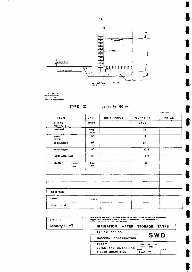
TYPE I capacity 60 m1
PRICI LIVIL
ITEM
bricks 220 • " 0 x 5 5 mm
cement
sand coarse
excavation
sand layer
refill with soil
i plaster »i>m
i «and
materials
labour
total cost
UNIT
piece
bag (40 Itr)
m»
m3
m3
m3
bag m1
mandaya
UNIT PRICE QUANTITY
13600
27
2
29
13.5
2.2
5 1
PRICE
|
TYPE I
Capacity 60 m3
THIS OESIQN WAS RIAUSEO UMOtN AUSPICE! OF TNI STEERING COMMITTEE WINOENEROT DEVELOPING COUNTRIES — 1*0 — »0 SOI SS ANtRSPOORT THI NETHERLANDS IM COOPERATION * ITH - T WO — AtttRSf OORT.
IRRIGATION WATER STORAGE TANKS
TYPICAL DESIGN
MASONRY CONSTRUCTION
TYPE I DETAIL AND DIMENSIONS BILLOF QUANTITIES
SWD
« • ! • 810707
TWO OHV

15
ground l«v«t
f fMUaith toil
1= a. a
i i i i _x~
220)
0 ^ I fl »s»o
I Imymi-
4 T
W 30 SO
—*—t 1 r—I r -0 * 0 40
teal* in c«ntfm«t«ft
TYPE X capacity 90 m3
PniCt LCVtL
ITEM
bricks 220 I 110 I 55 mm
cement
sand coarse
excavation
sand layer
refill with soil
plaster c«mt»i land
materials
labour
total cost
UNIT
piece
bag (40ltr)
m3
m3
m3
m3
bag m3
mtndiyt
UNIT PRICE QUANTITY
1 8 5 0 0
36
3
41
18.5
2.2
8 1.5
PRICE
TYPE I
Capacity 90 m3
THIS OCSIQM WAS RCAllSCD UNOCR AUtPICeS Of TMC STeiRIMQ COMMITTCI WIHDCMflQI OIVELOflNO COUNTKIIS — 1W0 — PO 10* IS AWERtfOOMT THI NETHERLANDS IN COOMRATION WITH — TWO —A«e*»FOOI»T.
IRRIGATION WATER STORAGE TANKS
TYPICAL DESIGN
MASONRY CONSTRUCTION
TYPE I DETAIL AND DIMENSIONS
8 ILLOF QUANTITIES
SWD
data 810707
TWO O M V

16
JC 9tom«m f «N
- * 4 -
T%f, T nRTTC W H W l 1X0
4-
A
0 K> 40
ae«4* in e * * i t lm* t« r i
TYPE I capacity 150 m3
HiiCI i.f«IL
I T E M
Trick* 2*0 I 1 1 0 . 5 * ••>
cement
• and coarse excavation
sand layer
rami with toil
piaster
UNIT
ptaca
b«9 (40 I * >
UNIT PRICE QUANTITY
32700
e4
PRICE
bag
S
TO
32
~Ts
11 2.S
materials
labour
total cost
I TYPE I
Capacity 150 m3
TMIt M l Mill « M MALIMO UHOI* AUlPtCEt 0* TM< S T I I I U M CO*J»<TTIf ttlNBCNiaOt o t v i i o p i n c c o u w r m i i — two — PO aot n A M P J » P O O » T TM« NtTMiaLANDS Ut C O O M B J A J I O * WITH —TWO —A«int«00«T.
IRRIGATION WATER STORAGE TANKS
TYPICAL DESIGN
MASONRY CONSTRUCTION
T Y P E I DETAIL AND DIMENSIONS
BILL OF QUANTITIES
SWD .
d i U 810707
TWO OHV

17
2.3.2. Watertank Type II
Page General lay-out 18 Work-instructions 19-20 Capacity 30 m3 21 Capacity 60 m3 22 Capacity 90 m3 23 Capacity 150 ra3 24

plans
I - t.4. - 4 hMM&M
U-m
if.
!•!•> 41 t(W/t<
sections
TYPE H
capacity 30 m' capacity 60 m1 capacity 00 m' capacity 150 m1
0 1 2 3 4 5
s e a l * In m « l « r t
THIB MCIGH WAS R U U I I O UHOtK AUS»>|Cfl Of TNI STICRIHO COMMIT TIE WIM0EMC«01 DEVfLOPINO COUMTMlit — *W0 — » 0 M I tS AMfRKFOORT TMI MCTMtRLAHOS IN COOPIKATlON W l T N - T W O - A M I U f F O O R T
IRRIGATION WATER STORAGE TANKS
TYPICAL DESIGN
MASONRY CONSTRUCTION
T Y P E H
GENERAL LAY OUT
SWD maaaura* in mm
dau aioaia
TWO | sn_._.

19
TYPE II
work sequence and description notes and recommandations
- clear the area of the site where the tank is proposed to be constructed
- remove a layer of approx. 400 mm of the topsoil
- when bad soil conditions are found - to avoid settlements of the bund (vegetation, blacksoil, loose surface earth wall soil) also the topsoil under the bund earth wall is to be removed
- refill with a sand and/or gravel layer of approx. 200 mm
- the refill is to be compacted with (self-made) tampers
- when the fill consists of sand only, the compaction can also be done by sprinkling with a little water, and ramming
- if necessary the surface is to be levelled
- mark the circumference of the tankslab with pegs (pegs core to core 1 metre)
- mix the cement and sand to a dry motar
- add water to the dry motar until the mortar can be handled well
- start bricklaying the tankslab - on the bottom of the tankslab the circumference of the tankwall can marked
- continue with bricklaying of the tankwall
- on top of the tankwall a bricklayer of edge coping is to be applied (see page 51)
- refill the outer circumference with soil
- the refill is to be compacted
- scrape out the joints of the inside of the wall and of the slab (approx. 20 mm) and apply a rendering (plaster) to the inner surfaces of of the tank
As indicated in the details (see page ...) the toplayer of the bottom should be started only after finishing the first layer The bonds are indicated in the details as well (see page ..) When the bricks are of a good quality and the sizes are approx. equal joints of + 12 to 15 mm are preferred take care of the joint between the tankslab and the tankwall the joints should be cleaned and moistened before bricklaying of the tankwall starts immediately after bricklaying (after each day) the finished parts of the tank are to be protected against weather influences

20
- refill a bund earth wall of approx. 0,65 m heigth around the hole circumference of the tank
- the refill is to be compacted
- therefore these parts should be moistened or covered during at least the first three weeks
- use the topsoil that was removed earlier

21
t , * i i i 0 K> 40
acala in c«nttm«l«r«
TYPE nr capacity 30 m3
PRICI nvi t
I TEM
bricks I t O i l t O i S S m m
cement
sand • • o . •''.••
excavation
sand layer
ref i l l with soil
bund
plaster c.m.m sand
m a t e r i a l s
labour
t o ta l cos t
UNIT
piece
bag ( 4 0 l t r l
mJ
m3
m3
m3
m3
bag m3
mandaya
UNIT PRICE QUANTITY
8300
19
2
16.5
7.4
1.6
20
3 0.6
PRICE
TYPE II
Capacity 30 m3
THIS DCtlOll WAS Rf ALIStO UN01R AUSPICIt OF TMC 1TIIRIHQ COMM1TTII WINOftMIRQf OfVILQEUia COUNTRIES — IWO — «>0 SOI Bft AMtRtFOORT THI HI THIRL A M M LM COO* • RAT ION W ITM — TWO — AMCRWOORT.
IRRIGATION WATER STORAGE TANKS
TYPICAL DESIGN
MASONRY CONSTRUCTION
TYPE H DETAIL AND DIMENSIONS
B ILLOF QUANTITIES
SWD
d«t« B10707
TWO O M V

O *)
| 1QHQ
L J."°.i. *"»°-ISO I I
I I I I I I 0 tO 40
sea l * in canlimatara
TYPE TT capacity 60 m1
' " I C I L t V I l
ITEM UNIT UNIT PRICE QUANTITY PRICE
b r i c k s I H i t t O i J S nam
piece 13600
cement bag 27
sand I :O. I I -S>-
excavation 29
sand layer m3 13.5
ref i l l w i th soil 2.2
bund
plaster camant
»and
bag
25.5
m a t e r i a l s
labour mandaya
t o t a l cos t
TYPE II
Capacity 60 m3
TNI1 OCtlOH tt*J MtAllSID UNOIR AUt»lC(t OF THt tTt t l t t l ta COMMITTEI triMOCMfRQV ocviLQruta C O U N T N I C I — w o — ao a o i u aMtairooRT T M I NCTHCRLANDS in COOPERATION WITH — TWO — AtHNSFOORT.
IRRIGATION WATER STORAGE TANKS
TYPICAL DESIGN
MASONRY CONSTRUCTION
TYPE I t DETAIL AND DIMENSIONS
B ILLOF QUANTITIES
SWD
data 810707
TWO OMV O.. C < — > ! ' » > • •

2 3
.ground U v l
Mill.,mift Mil
plaaf r
fir CTMI11III[1|IIIMI
- - ^ v
., t < " ° r L arasao
tt as ao I I I I I I 0 tO 40
•calo in contlmotor*
TYPE Ot capacity 90 m3
f lUCl LtVIL
ITEM
br ick * 2Mi110»S5 mm
cement
sand co;lr^.',
excavation
sand layer
ref i l l with soil
bund
plaster comont sand
mate r i a l s
labour
t o ta l cos t
UNIT
piece
bag (40 I t r l
m»
m3
m3
m3
m3
bag m3
mindiyi
UNIT PRICE QUANTITY
18500
36
3
41
18.5
2.2
35
8 1.5
PRICE
TYPE II
Capacity 90 m3
THIS DESfOJ. WAM n i A l l t f O UMOIX AUSPICK* OF TNI «TCINlNQ COMMITTED WIMOfHIHOT OfVKLOFUU) COUNTRIIt — IffD — »0 «01 U AMIfttFQOHT THi HETMCRLAMOS LM COQ#C«AJIOM WITH — TWO — A«e*tFOONT.
IRRIGATION WATER STORAGE TANKS
TYPICAL DESIGN
MASONRY CONSTRUCTION
TYPE H DETAIL AND DIMENSIONS
B ILLOF QUANTITIES
SWD m i l i u m m mni
data 810707
TWO DMV

24
1 1 1 J~330*L,
• : • • • . ' . . - - V V , •: • • ' . . ..i
\ tend layer
0 12360
.*?..
10 30 90
0 20 40
seal* in centimeters
TYPE H capacity 150 ma
PRICE LEVEL
ITEM
bricks 220 K 1 1 0 * 5 5 mm
cement
sand rn.irj- •
excavation
sand layer
refill with soil
bund
plaster
materials I | labour
total cost
cement
sand
UNIT
piece
bag 140 II r |
m3
m3
m3
m3
m3
bag m3
mandays
UNIT PRICE QUANTITY
32700
64
5
70
32
35
39
11 2.5
! I j PRICE
! ;
j
• i
' \
-
i i
TYPE II
Capacity 150 rtj3
THIS O f S i C N WAS REALISED UNDER AUSPICES OF THE STEERING COMMITTEE WiNOENERGv D E V E L O P I N G COUNTRIES — SWO — PO S O I S9 AMERSFOORT THE NETHERLANDS IN COOPERATION W I T H — T W 0 — A ME R SFOO R T .
IRRIGATION WATER STORAGE TANKS
TYPICAL DESIGN
MASONRY CONSTRUCTION
TYPE3E DETAIL AND DIMENSIONS BILLOF QUANTITIES
SWD measures m mm
date 810710
TWO 13 N V

1 I 25
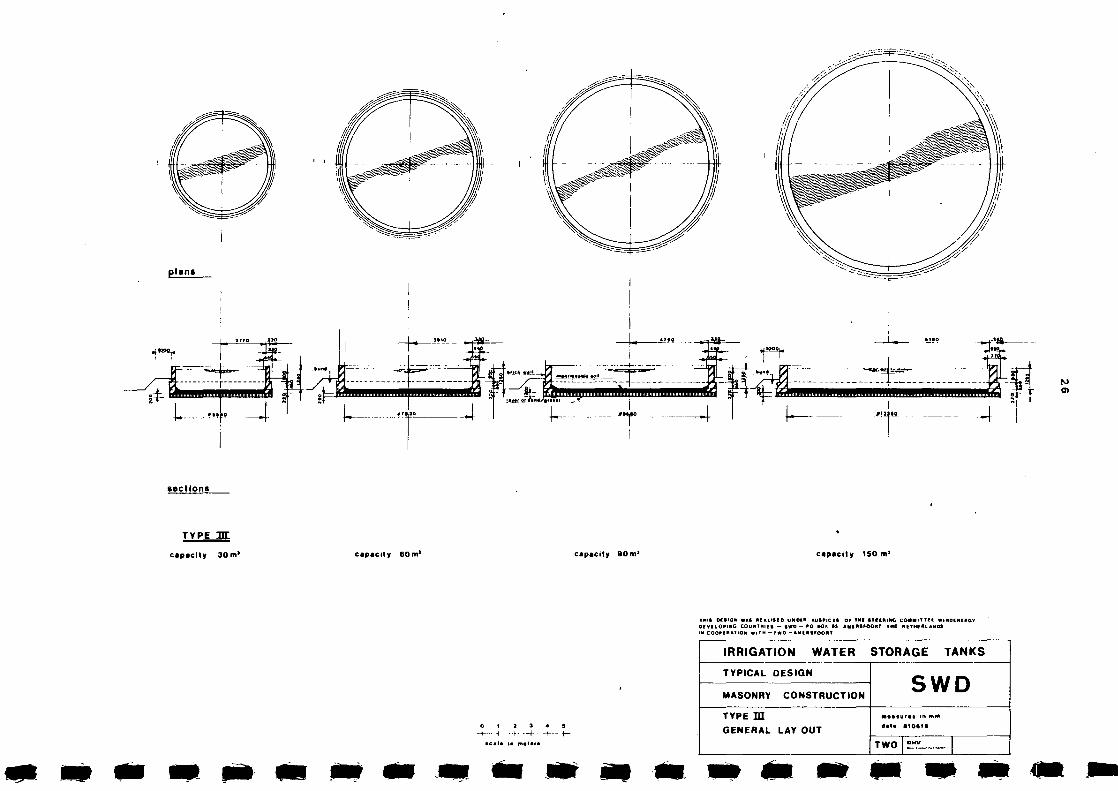
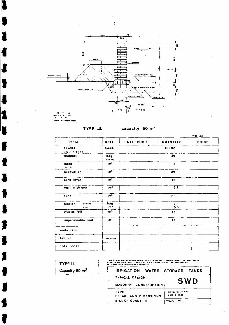
2.3.3. Watertank Type III Page
General lay-out 26 Work-instructions 27-28 Capacity 30 m3 29 Capacity 60 m3 30 Capacity 90 m3 31 Capacity 150 m3 32
plans
«t * * * f i
ii :fc_
4
sections
TYPE UL
capacity 30 m' capacity 60 m1 capacity 90 m1 capacity ISO m>
0 1 2 3 4 5 H 1 ..}. —i- • - t — - t -
THIS OCflON W * t REACHED UNDER AUS'lCE* OF TMI ( T U R I N G COMMIT T i l WINDENCRGv OEVElOPING COUNTRIES — SWO — » 0 BOX • » AMIRtFOORT THI NETHERLANDS IN COOPERATION N l T H - I N O -AMERtPOORT
IRRIGATION WATER STORAGE TANKS
TYPICAL DESIGN
MASONRY CONSTRUCTION
TYPE H I
GENERAL LAY OUT
SWD m«»turoi m RIM d«i» aioaia
TWO 1 °rr:
27
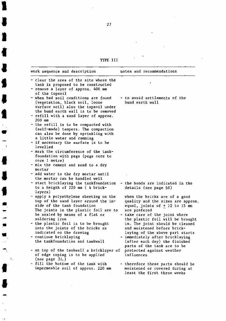
TYPE III
work sequence and description notes and recommendations
clear the area of the site where the tank is proposed to be constructed remove a layer of approx. 400 mm of the topsoil when bad soil conditions are found (vegetation, black soil, loose surface soil) also the topsoil under the bund earth wall is to be removed refill with a sand layer of approx. 200 mm the refill is to be compacted with (self-made) tampers. The compaction can also be done by sprinkling with a little water and ramming if necessary the surface is to be levelled mark the circumference of the tank-foundation with pegs (pegs core to core 1 metre) mix the cement and sand to a dry mortar add water to the dry mortar until the mortar can be handled well start bricklaying the tankfoundation -to a heigth of 220 mm ( 4 bricklayers) apply a polyethylene sheeting on the top of the sand layer around the inside of the tank foundation The joints in the plastic foil are to be sealed by means of a flat or soldering iron the plastic foil is to be brought into the joints of the bricks as indicated on the drawing continue bricklaying the tankfoundation and tankwall
on top of the tankwall a bricklayer of of edge coping is to be applied (see page 5.1.) fill the bottom of the tank with impermeable soil of approx. 220 mm
to avoid settlements of the bund earth wall
the bonds are indicated in the details (see page 50)
when the bricks are of a good quality and the sizes are approx. equal, joints of + 12 to 15 mm are prefered take care of the joint where the plastic foil will be brought in. The joint should be cleaned and moistened before bricklaying of the above part starts immediately after bricklaying (after each day) the finished parts of the tank are to be protected against weather influences
therefore these parts should be moistened or covered during at least the first three weeks

28
- refill the outer circumference with soil
- the refill is to be compacted - scrape out the joints of the inside of the wall (approx. 20 mm) and apply a rendering (plaster) to the inner surfaces of the tank
- refill a bund earth wall of approx. - Use the topsoil that was removed 0,65 height around the hole circum- earlier ference of the tank
- the refill is to be compacted
j{
Type III and type IV are variants. Minor differences in respect of the quantities of materials incorporated in the types III and IV are indicated in the schedule of quantities.

2 9
ground le
x aand laytr
- i . . * - " 0 •
330 ^ ^ 5540
10 30 30
0 20 40
t e a l * in centimeters
TYPE HL capacity 30 m3
PRICE LEVEL
ITEM
bricks 220, 110iSS mm
cement
sand
excavation
sand layer
refill with soil
bund
plaster ttmmi sand
plastic foil
impermeable soil
materials
labour
total cost
I UNIT I UNIT PRICE
piece j
bag (40llr |
m3
m3
nv>
m3
m3
bag m3
m2
m3
mandaya
QUANTITY
5 4 0 0
11
'
15
6.7
1.7
20
1 0.3
22
5.3
PRICE
i
I I I
j i I
I
j
!
•
TYPE III
Capacity 30 m.3
THIS OES1CN WAS REALISED UN0EB AUSPICES OF THE STEERING COMMITTEE W'NOENERGV DEVELOPING COUNTRIES — SWD — PO BO* 84 AMERSFOORT THE NETHERLANDS IN COOPERATION W I T H — T WO — A ME RSFOO« T .
I IRRIGATION WATER STORAGE TANKS
TYPICAL DESIGN
i MASONRY CONSTRUCTION
TYPE OH
DETAIL AND DIMENSIONS I BILLOF QUANTITIES
SWD measure s in mm
dale 810707
TWO 13 H V

30
__ I._
- I -S
inb 440 I 0 7820
10 30 SO
0 20 40
»c»l» in c*Mtm»t«rs
TYPE HE capacity 60 m3
P«ICE LEVEL
ITEM
bricks 2 2 0 i n o , 5 5 mm
cement
UNIT
piece
bag 1*0 I t l )
UNIT PRICE QUANTITY
11200
22
PRICE
sand 1.8
excavation
sand layer
28
refill with soil
11
2.2
bund 24
plaster t.mi«i tand
plastic (oil
impermeable soil
la ter ia ls
bag 2 0.4
32
11
labour
total cost
TYPE III
Capacity 60 m3
THIS OESIGN WAS REALISED UNDER AUSPICES Of THE STCCRING COMMITTEE WINOENERGV D E V E L O P I N G COUNTRIES — Swo — P 0 B O l 89 AMERSfOORT THE NETHERLANDS IK COOPERATION W I T H — TWO — AidERSFOORT.
IRRIGATION WATER STORAGE TANKS
TYPICAL DESIGN
MASONRY CONSTRUCTION
TYPE M. DETAIL AND DIMENSIONS
BILLOF QUANTITIES
SWD
flat* 810707
TWO OHV
31
T_
I-O
to >o so
0 30 40
scala m cantimatart
n-~0-^-
TYPE M capacity 90 m3
ITEM
bricks 220. 110«55 mm
cement
sand ri\:\i -,t-
excavation
sand layer
refill with soil
bund
plaster cem.m tand
plastic foil
impermeable soil
materials
labour
total cost
! UNIT i
" 1
—
piece
bag (40 It')
m3
m3
m3
h" ~m3
m3
bag m3
m2
m3
mandayt
UNIT PRICE
—
QUANTITY
13000
26
2
39
18
2.2
36
3 0.5
45
19
• • • i
•
PRICE LEVEL
i PRICE |
1
1
i
!
TYPE III
Capacity 90 m3
THIS OCS'CM WAS AEAL>SCO U N O E * AUSPICES Q* THE STEERING COMMITTEE WINOCNEHQ* DEVELOPING COUNTRIES - SWO — PO I O t B* AMERSFOORT THE NETHERLANDS IN COOPERATION W I T H — T WO - A M E " SFOQ" T
IRRIGATION WATER STORAGE TANKS
TYPICAL DESIGN
MASONRY CONSTRUCTION
TYP£ M. HETAIL AND DIMENSIONS
| BILLOF QUANTITIES
SWD m « i i u n & >n mm data 3107D7
TWO D H V

32
10 30 50
0 10 40
seal* in centimeters
TYPE JH capacity 150 m3
ITEM
bricks 2 2 0 , U O i S S mm
cement
sand
excavation
sand layer
refill with soil
bund
plaster c«m«nt sand
plastic foil
impermeable soil
materials
labour
total cost
—
—
UNIT
piece
bag I40 I t t I
m3
m3
^ m 3
m3
bag m1
m*
nV
! msndays i
i
UNIT
-
PRICE QUANTITY J
2 3 5 0 0
4 6
3.6
65
31
2.5
38
3 0.6
54
26
PRICE LEVEL
PRICE I
j
!
i
i
!
|
TYPE III
150m3
THIS OCSIGN WAS REALISED UNOER AUSPICES OF THE STEERING COMMITTEE WINDENERQY D E V E L O P I N G COUNTRIES — swo — PO sOx as AwensFOORT T H C NETHERLANDS IN COOPERATION WITH— TWO —AMERSFOORT.
IRRIGATION WATER STORAGE TANKS
TYPICAL DESIGN
MASONRY CONSTRUCTION
TYPE :nr DETAIL AND DIMENSIONS BILL OF QUANTITIES
i
SWD m a i l u i t i in mm
a a t . 910710
TWO IJMV

33
2.3.4. Watertank type IV
Page General lay-out 34 Work instructions 35-36 Capacity 30 m3 37 Capacity 60. m3 38 Capacity 90 m3 39 Capacity 150 m3 40

pl«n»
#M,IO
-4—
i : 1 •i-t—-• T
>J0 ir
~"*"i n o i *
3- CO
x c t l o n t
TVPE EC
capacity 30 m' o p a c i t y 60 m' capacity 90 m> capacity 150 m*
0 1 J 1 4 5
• c a l * in «•••»>
fHIt OttlON «At MIALHIO UMD1M AUSFICIt 0 ' THf fTIIHIMQ COMM^'II WIHDfNtRGv 0(VIk.0PIHC COUNTMltt — *WO — HO M * *» AMlHtfOOMT IMi NtlHiftLANDt n coo*i"»'ion WITH - t w o — AMIutroopi
IRRIGATION WATER STORAGE TANKS
TYPICAL DESIGN
MASONRY CONSTRUCTION
TYPE J3Z
GENERAL LAV OUT
SWD M « « I U ( * » in mm
TWO |srr.-. |

35
TYPE IV
work sequence and description notes and recommendations
clear the area of the site where the tank is proposed to be constructed remove a layer of approx. 400 mm of the topsoil when bad soil conditions are found (vegetation, black soil, loose surface soil) also the topsoil under the bund earth wall is to be removed refill with a sand layer of approx. 200 mm
the refill is to be compacted with (self-made) tampers. The compaction can also be done by sprinkling with a little water and ramming if necessary the surface is to be levelled
mark the circumference of the tank-foundation with pegs (pegs core to core 1 metre) mix the cement and sand to a dry mortar add water to the dry mortar until the mortar can be handled well start bricklaying the tankfoundation to a heigth of 220 mm ( 4 bricklayers) apply a polyethylene sheeting on the top of the sand layer around the inside of the tank foundation The joints in the plastic foil are to be sealed by means of a flat or soldering iron the plastic foil is to be brought into the joints of the bricks as indicated on the drawing continue bricklaying the tankfoundation and tankwall
to avoid settlements of the bund earth wall
on top of the tankwall a bricklayer of of edge coping is to be applied (see page 51) fill the bottom of the tank with impermeable soil of approx. 220 mm
the bonds are indicated in the details (see page 50)
when the bricks are of a good quality and the sizes are approx. equal, joints of + 12 to 15 are prefered take care of the joint where the plastic foil will be brought in. The joint should be cleaned and moistened before bricklaying of the above part starts immediately after bricklaying (after each day) the finished parts of the tank are to be protected against weather influences
therefore these parts should be moistened or covered during at least the first three weeks

36
- refill the outer circumference with soil
- the refill is to be compacted - scrape out the joints of the inside of the wall (approx. 20 mm) and apply a rendering (plaster) to the inner surfaces of the tank
- refill a bund earth wall of approx. - Use the topsoil that was removed 0,65 height around the hole circum- earlier ference of the tank
- the refill is to be compacted
Type III and type IV are variants. Minor differences in respect of the quantities of materials incorporated in the types III and IV are indicated in the schedule of quantities.

37
- - • ? -
220
[ 220
6 6 0
l^iHO 1
» i 1 100° I
I
10 90 SO
0 20 40
» < : * • • in c a n t > m a t « r s
TYPE 3 1 capacity 30 m3
PRiCE LEVEL
ITEM
bricks 220 i 110x55 mm
cement
sand co-irci'
excavation
sand isver
refill with soil
bund
plastic foil
plaster c.m.m sand
impermeable soil
materials
labour
total cost
UNIT
piece
bag («0 l!r|
m3
m3
m3
m3
m3
m2
bag m3
m3
mandays
UNIT PRICE QUANTITY
5 4 0 0
11
i
" 8
1.8
23
35
2 0.5 4.5
PRICE
i
i I
i
!
i
TYPE IV
Capacity 30 m3
THIS DESIGN WAS REALISED UNOER AUSPICES OF THE STEERING COMMITTEE WINOEMERGr DEVELOPING COUNTRIES — SWO — * 0 BOX 8S AMERSJOORT THE NETHERLANDS IK COOPERATION W I T H - T w O — AMERSFOORT.
IRRIGATION WATER STORAGE TANKS
TYPICAL DESIGN
MASONRY CONSTRUCTION
TYPE 3E DETAIL AND DIMENSIONS
BILLOF QUANTITIES
SWD m i l i u m irt mm data 810707
TWO OHV

38
I 1
' • ' i l l with ioi l
\ Ui>d l a y r
220
T - — ^ — H -
Jg~ 7 8 2 0
10 30 M
O 20 «0
teal* m c»nt»m»t»t»
TYPE HZ capacity 60 m3
»»ICi LlTVfl
ITEM
b r i c k s 220 « H O i S S mm
cement
sand conrsR
excavation
sand layer
refi l l with soi
bund
plastic toi l
plaster
impermeable
m a t e r i a l s
labour
t o ta l cost
- -
1
c i m i n t
sand
soi l
H
- 1
UNIT
piece
bag 140 I t t )
m3
m3
m3
m3
m3
m2
bag m 3
m 3
ffllndlyi
UNIT PRICE
- -
•
QUANTITY
8900
18
1.5
30
13.5
2.4
26
65
2 0.5
9.3
I
• • r
L I i
! PRICE
i
i
.
i
i
TYPE IV
Capacity 60 m3
'«•» OISICN WAS M A l ' M O UNDID AUS»IC«» O* TM| STffW'NG COMMlTTCI WIMOCNEHGT O Iv i lOHt tG COUNrlllS - 1WD — »0 tO l IS AMCHSFOORT T N ( N E T M C H .NOS IN COOfl RATION WMfM - r WO — *H««S*00"T
IRRIGATION WATER STORAGE TANKS
TYPICAL OESIGN
MASONRY CONSTRUCTION
TYPE 3E. DETAIL AND DIMENSIONS
B ILLOF QUANTITIES
SWD
data 810707
TWO

3 9
f«iii< with too.
V^ pl»*tlC toil
0 9580
K> K M
0 30 40
teal* <n c«ntim«t*fs
^ 1000
f__
T -
TYPE 33L capacity 90 m3
PRICE t i v e i
ITEM
b r i c k s 220. 110 « 55 mm
cement
sand coarse
excavat ion
sand layer
ref i l l with soil
bund
plastic foi l
plaster csm«nt sand
impermeable soil
m a t e r i a l s
labour
t o ta l cos t
—
—
- -
UNIT
piece
bag I4C ltd
m3
m3
• •
m3
m3
m>
bag m 3
_ m3
mandayt
UNIT PRICE
.
QUANTITY
9 6 0 0
20
1.5
' 41
18.5
2^2
35
92
3 0.5
19
1 1 PRICE !
i i 1
; i ! i
1
1
i '.
\ \ i 1
TYPE IV
Capacity 90 m3
TMiS O f S i O N WAS dEALISEO UNOER A U S ' I C C S OF TMC STEERING C O M M I T T E E WIMOENCRGV
D E V E L O P I N G COUNTRIES - S * 0 — WO »OX t»S A M f R S ' O O f t T THE HI THtftL AMDS
»N COOPERATION W I T H — I WO — * M ( * 9 f O O « T
IRRIGATION WATER
TYPICAL DESIGN
MASONRY CONSTRUCTION
TYPE I T DETAIL AND DIMENSIONS
BILLOF QUANTITIES
STORAGE TANKS
O \ki r\ J V V U
m i l l u ' t i in mm
(•••• 810707
TWO OHV

40
TYPE HZ. capacity 150 m1
»MICC LEVEL
ITEM
bricks 220. 110.55 mm
cement
sand i:o;irsf
excavation
sand layer
refill with soil
bund
plastic foil
plaster cimmi sand
impermeable soil
materials
| labour
total cost
UNIT
piece
bag I40ltr)
m3
m3
m3
mJ
m3
m2
bag m 3
m 3
mindiyt
UNIT PRICE 1 1
QUANTITY ! PRICE
17750
34 i < |
2.7 i |
70
33 ; |
4 3 !
39
160
3 i ' 0.5
24
; j
I I i I
THIS 0 C S I G N WAS REALISED U N O t N AUSPICES OF THE STEERING COMMITTEE W I N O E N J E R G V O E V E L O P I N G COUNTRIES — SWO — * 0 8 0 1 A3 AUERSPOORT THE NETHERLANDS IN COOPERAJlON W I T H — T W O — A M E R S f O O M T .
IRRIGATION WATER STORAGE TANKS
TYPICAL DESIGN
MASONRY CONSTRUCTION
TYPETX DETAIL AND DIMENSIONS
BILLOF QUANTITIES i
SWD m t i i u r t s in mm d u e 810707
TWO D H V
TYPE IV
Capacity 150 m3
41
2.3.5. Watertank type V
page General lay-out 42 work instructions 43-44 Capacity 30 m3 45 Capacity 60 m3 46 Capacity 90 m3 47 Capacity 150 ra3 48
f I

plans
JJQ
IT
it ' H I 1
n o r
'TL-
sections
TYPE 3E
capacity 30m* capacity 6 0 m ' capacity 90nt3 capacity 150 m'
0 1 2 3 4 »
- t — 4 • t • 1 » • - • * -
• c a l * in m « t » f s
THIS M S I C N W*t N I A L I I I O UNBtR AUSPtCIS OF THC «T| |P(MO COMMlTTIC WiMOtNtftOV OIVtLOPING COUNTHliS — tWO —PO M » • » *MC*«FOOMT THE MITHIHLANDC IN COO^tKATION « l l l " - T « 0 - * i t « l i a O « l
IRRIGATION WATER STORAGE TANKS
TYPICAL DESIGN
MASONRY CONSTRUCTION
TYPE 3Z
GENERAL LAY OUT
SWD
4st« tioaie
TWO | 5T.*l |

43
TYPE V
work sequence and description notes and recommendations
clear the area of the site where the tank is proposed to be constructed remove a layer of approx. 400 mm of the topsoil refill with a sand layer of approx. 200 mm the refill is to be compacted with (self-made) tampers. The compaction can also be done by sprinkling with a little water and ramming if necessary the surface is to be levelled mark the circumference of the tank-foundation with pegs (pegs core to core 1 metre) mix the cement and sand to a dry mortar add water to the dry mortar until the mortar can be handled well start bricklaying the tankfoundation to a height of 220 mm (4 bricklayers) apply a polythene sheeting on the top of the sand layers. The joints in the plastic foil are to be sealed by means of a flat or soldering iron the plastic foil is to be brought into the the joints of the bricks as indicated on the drawing
fill the bottom of the tank with a sand layer of 110 mm so that the plastic foil is closed up and protected against damages continue bricklaying the tankfoundation and tankwall on top of the tankwall a bricklayer of edge coping is to be applied (see page 51)
apply on the bottom of the tank a second layer consisting of bricks without mortar (110 mm) refill the outer circumference with soil the refill is to be compacted
the bonds are indicated in the details (see page 50) when the bricks are of a good quantity and the sizes are approx. equal, joints of + 12 to 15 mm is prefered take care of the joint where the plastic foil will be brought in. The joint should be cleaned and moistened before brichlaying of the above part starts, immediately after bricklaying (after each day) the finished parts of the tank are to be protected aginst weather influences. Therefore these parts should be moistened or covered during at least the first three weeks

44
scrape out the joints of the inside of the wall (approx. 20 mm) and apply a rendering (plaster) to the inner surfaces of the tank bold two tie rods made of steelstrips - it is advisable to protect around the tankwall (for details see the tierods against corrosion page 53.) in advance, (painting, hot
deep galvanised)
This type of tank not to be used in hot and dry tropical countries

4 5
ground laval
tmiilLjwith aoi|
to so so
0 20 40
seal* in cantimatart
T
" I -
tiarods mad* ol stealitrips
-H""T,I 11111111 mxs: *r
x̂ plasiic toil
__a. taad-layj .
TYPE I E capacity 30 m3
PKtCt LEVEL
ITEM
bricks 230 i 110 i » 5 mm
cement
sand ro.irsc
excavation
sand layer
ref i l l with soil
br icks SisD
plastic foil
plaster c«m«m sand
t ierods
i m a t e r i a l s
labour .
total cos t
UNIT
piece
bag <40 l t r )
m3
m 1
m3
m3
piece
m2
bag m 3
6,26 m"
(Vi and ays
UNIT PRICE QUANTITY
5400
11
1
17
a
1.8
1450
35
I, 6
I PRICE I
!
• i i
i
i i ;
|
I
TYPE V
Capacity 30 m3
THIS DESIGN WAS REALISEO UNOSR AUSPICES OF T H i STEERING C O M M I T T E E WINOCNERGY D E V E L O P I N G COUNTRIES — SWO — RO 1 0 1 *S AMCRSFOORT THE NETHERLANDS IN COOPERATION W I T H - T WO — AMCRSFOORT .
! IRRIGATION WATER STORAGE TANKS
TYPICAL DESIGN
MASONRY CONSTRUCTION
TYPE 3C ! DETAIL AND DIMENSIONS I 8 I L L 0 F QUANTITIES
SWD
data 810707
TWO D H V

46
ti*rods mad« ol staalstnps
ground !•*•!
ra Ml yil_n ton
to JO »o
o ao «o teal* in c*r*tim*t*ri
i C3Sr
m ji^7Tpi.}i,.i.i,i,iHii,i > v
Tfist
| plaatic loil
> . 0 7820 \Mtui l»yi f
TYPE 3E capacity 60 m3
»HCI LCVIL
ITEM
b r i c k s * 220» MQiSS mm
cement
sand COAT/'
excavation
sand layer
ref i l l with soil
br icks slab
plastic foil
p l a s t e r crmtnl sand
t ierods
m a t e r i a l s
labour
i t o ta l cos t 1
UNIT
piece
bag 140 llfl
mJ
m3
m3
m3
UNIT
.
piece | j
m 2
bag _mj 8,65 m'
mindiyi
•
PRICE !
QUANTITY
8900
18
1,5
30
13.5
2.4 | i
2850
65
PRICE
2 0.5 6
-!
I |
i
i
•
i
!
i i
I
TYPE V
Capacity 60 m3
TNlB OfSlON WAS RIALISIO UMOIR AUtPICtl OF TMI tTflRINC COM**ITT(f WIHOENIRO* OfVllORINQ COUftTNllt — »«0 — PQ aOI •» AMMS'OORr TMfl NETM1RLAN0S IN COOM NATION WITM — r WO — A MERS'OORT
IRRIGATION WATER STORAGE TANKS
TYPICAL DESIGN
MASONRY CONSTRUCTION
TYPE 3C DETAIL AND DIMENSIONS
! 8 I L L O F QUANTITIES I
SWD m t a l u r t i in mm data 810707
TWO ST"-....._.

4 7
•rods mads of • t i t fs t r ip t
8
V-""T' istn_i_j*itr> toil
» ••//A , n , i i , C\ I,i i,i 11 i i 11 i l l n
,-/M\ 1 I fV.r.-iv;.--\:w-::.:..::
W M> 5 0
—*- • *- i- t --*- — 0 » 40
•cat* in c«nt<m*t«r*
TYPE 3C capacity 90 m1
« l C l L tVH
ITEM
bricks 220i <10«55 mm
cement
sand CIW5P
excavation
sand layer
refill with soil
bricks slab
plastic foil
, plaster c.m.m sand
tierods
materials
labour
total cost
UNIT
piece
bag 140 n o
m3
m3
m3
m3
piece
"~'m2"
bag m 3
10,26 m'
mindiyi
UNIT PRICE QUANTITY
9600
20
1.5
41
25.6
2.2
4500
80
3
0.5
6
PRICE j
i I
i
I
r •
i
!
•
i
i
TYPE V
Capacity 90 m3
THIS Of SIGN WAS N C A L I S I O uNOfn * u t r i c f l or TMI s r i l R m c C O * » * I T T I I wmocwfitcr o c v t L O P I N G couNTHiEi - *wo - PO ao« ai A M I R S F O O R T TM« MCTMCRLAWOS IN COOPf RATION WITH — TWO —AMIRtPOORT.
• IRRIGATION WATER STORAGE " TANKS
TYPICAL DESIGN
MASONRY CONSTRUCTION
TYPE 3C DETAIL AND DIMENSIONS
| BILLOF QUANTITIES
SWD m«a«ij(*A • " mm
dat* 810707
TWO D N V

48
0 » 40
•cat* in cantlmatara
tiarods mada of ttaalttripa .
r
3= -
-H+
TYPE X capacity 150 m5
»«ICt klVIL
ITEM
bricks 220 1110 i s 5 mm
cement
sand coarse
excavation
sand layer
ref i l l wi th soi l
b r icks tlab
plast ic fo i l
p laster cem.ni • And
t ie rods
m a t e r i a l s
labour
t o t a l cos t
UNIT
piece
bag (40ltr)
m5
m3
m 3
m3
piece
m*
bag m3
13,63 m'
mandays
UNIT PRICE QUANTITY
17700
34
3
70
32
4.5
7550
160
3 0.5
6
r PRICE
TYPE V
Capacity 150 m3
THtt Ottiate WAS MAI . 1*10 UWOIH AU*I . . _* Or TMC tTttHlHO COMMIT T * t VIMOtMCftQT oiviLOPma court runs — two — PO I O I u AMCRSFOORT TMI MTMIULANDI IM C0O*IaA7tOM WITH-TWO—AUfP-tPOOHT.
IRRIGATION WATER STORAGE TANKS
TYPICAL DESIGN
MASONRY CONSTRUCTION
TYPE I
DETAIL AND DIMENSIONS
BILLOF QUANTITIES
SWD
data 810707
TWO OMV

49
2.3.6. Typical details
Page Details brickwork bond, for a wall 50 Details brickwork bond, brick on edge coping 51 Details brickwork bond for the floorslab 52 Details tierods made of steelstrips 53

< 220 mm
brickwork bond for a wall of 220 mm thickness
330 mm
brickwork bond for a wall of 330 mm thickness
T -440 mm
brickwork bond for a wall of 440 mm thickness
T H I S 0ESIGN WAS R E A L I S E O UNDER AUSPICES OF THE STEERING COMMITTEE WINOCNERG*
D E V E L O P I N G COUNTRIES — SWO — f>0 BOH 6 * AMERSFOORT THE NETHERLANDS
IN COOPERATION W ITH — T WO — A M E R S f OORT.
IRRIGATION WATER STORAGE TANKS I
f 1
TYPICAL DESIGN
MASONRY CONSTRUCTION SWD
DETAILS
BRICKWORK BOND
m m u r a t in i 6 * t * 810715
TWO

220 mm
brick on edge coping for a wall of 220 mm thickness
brick on edge coping for a wall of 330 mm thickness
brick on edge coping for a wall of 440 mm thickness
440 mm
THIS DESIGN WAS REALISED UNDER AUSPICES OF THE STEERING COMMITTEE MMNOENERGV D E V E L O P I N G COUNTRIES — SWD — PO ROX 8S AMERSPOORT THE NETHERLANDS IN COOPERATION W I T H — T WO — A ME RSF0ORT .
IRRIGATION WATER STORAGE TANKS
TYPICAL DESIGN
MASONRY CONSTRUCTION
DETAILS
BRICKWORK BOND
SWD
o a t * 810713
TWO OMV
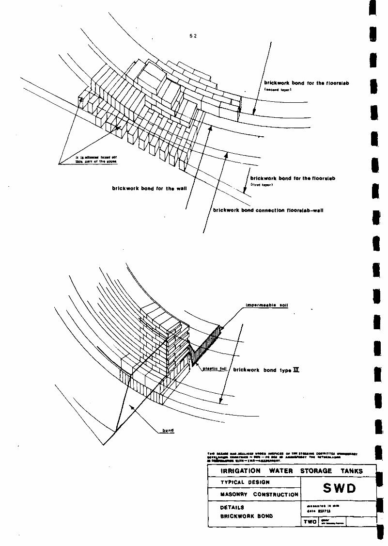
brickwork bond for tha flooralab
/ brickwork bond for tha flooralab / (flrit l«r»tl
brickwork bond connection flooralab-wall
Unp>fm»«bl« toil
pi.mc foil / brickwork bond typo H
m tuiaa M M n i i m i • • * • • twnci
• I f !•» !••—I«IW
u o» mi tTtnaw COMBITTU i MWOMT TMI M T M l i A M
IRRIGATION WATER STORAGE TANKS [
TYPICAL DESIGN
MASONRY CONSTRUCTION
DETAILS
BRICKWORK BOND
SWD | «••>• ' • • la • • 1 <•!• U07U 1
TWO mf

5 3
tierods mada of steelsfrips
divide the steelstrip into three parts
H=H^
connecting detail
r
I: :~wsr: ' — •
M 20
M"20~"
30
T~
mr
w-
THIS O C H C N WAS R E A H S E D UNDER AUSPICES OF THE STEERING COMMITTEE WINOENERGV D E V E L O P I N G COUNTRIES — SWD — PO S O I SS AMERSFOORT THE NETHERLANDS IM COOPERATION W I T H — T WO — AMERSFOORT.
IRRIGATION WATER STORAGE TANKS
TYPICAL DESIGN
MASONRY CONSTRUCTION
DETAILS
BRICKWORK BOND
SWD
» U 810715
TWO OHV

54
2.4. Testing
2.4.1. Introduction
If possible it is recommended to test the materials to be used. The descriptions in this chapter will give some guidelines for testing of bricks, local available.
The question arises how a brick wall in the field or on a farm should be tested to obtain information about cracks and collapse. The critical moment is the moment when the brick wall begins to crack, since in a cracked wall leakage will occur and the tank will be unsuitable. In developing countries test equipment is not always available. Therefore it must be determined with limited means, whether the brick, the mortar and the brick wall are of such quality that with a reasonable certainty the watertank can be constructed without risk of collapse. If test equipment is available, it is strongly recommended to make use of it. However, we assume that the only way to test a brick wall will be to use local materials and local equipment.
2.4.2. Testing construction materials
2.4.2.1. Choice of bricks
The choice of bricks depends on: a. the functional requirements b. the waterproof requirements c. the climatic circumstances
At testing, a brick must be able to withstand a compressive stress of at least 10 N/mm2. A "brick for damp proof work" is the most suitable one. The bricks can be examined as to their outward, physical and mechanical properties. Bricks with visible hair cracks must be discarded.
With a little practice it is possible to judge the quality of bricks by hitting them against each other and noting the resonance. A clear sound generally indicates a brick of good quality and of highly tensile and compressive strength.
Another method of determining the specific gravity of the bricks is to find the density. The density has a direct relationship with the waterproof quality and stress-resistance properties of a brick type. A specific gravity between 19 kn/m3 and 21 kn/m3 indicates a "brick for damp proof work". A standard brick (220*110*55 mm) will then weigh 2,66 kg.

55
The choice of the brick is also depending on the prevailing climatic conditions. In countries with changes in humidity and temperatures cracking due to shrinkage may occur (bricks with a low specific shrinkage percentage are advisable). In frost-prone areas the watertank should be emptied before the frost period starts.
2.4.2.2. Simple field identification tests for soil
Preliminary
Look at the whole sample. Is it mainly a coarse or fine soil? Are there any fibres or roots? Is it dull or dirty?
a. Appearance
If the soil is fibrous or dirty in appearance, test for organic material.
b. Feel
Sands and gravel feel coarse and gritty. Silts and clay are hard or floury when dry and soft or sticky when wet. Clay when wet will stain the fingers and can only be removed by washing.
c. Composition
Estimate how much of each fraction is in the soil and separate coarse from fine material by hand.
d. Organic (smell) test
Take a sample of the soil and smell it. If it has an earthy or vegetable smell it is probably organic. Warm the sample and the odour will become distinct.
Vibration test
(For particle size distribution). Place a dry sample on a board. Hold the board at a slope and tap lightly with a stick. The finer material will move up the slope or remain in place, the coarser will move down the slope.

56
If there are many different sizes between the largest and the smallest, the sample is well-graded. This means it will compact well. If only a few sizes can be seen, then it is single-sized or poorly graded.
Settling test
This test can also be used to determine the amount of soil (dirt) in river sand used for masonry or concrete work.
Place a sample in a bottle or a glass jar with straight sides. Then put it down to allow the mixture to settle. Gravel and coarse sand will settle immediately. Fine sand and coarse silt will settle more slowly taking about 30 seconds. Clay and fine silt fractions will not settle for several hours.
In the sample, the approximate quantities of each size can be seen as layers, the finer materials being different in colour. For sand which is used for masonry and concrete work, the amount of clay and silt must be less than 6%, otherwise the sand has to be washed.

57
\ f
<r COARSe.
Cohesion test
(To show whether there is sufficient building material in the soil).
Take a handful of damp material sample and mould it into a ball. a. With gravels the material will not stick together unless there are
fine materials present. b. With sands the damp material will stick together, but if no fine
materials are present it will crumble at a touch. c. If the ball stays together, even when placed on a sheet of paper,
silts or clays are present, which means the material is suitable for building.
2.4.3. Testing masonry construction
2.4.3.1. Testing of a brick wall
To be able to obtain any indications with respect to the tensile strength of a complete brick wall a test can be carried out and is described here. There are of course many test methods, but for the countries referred to above a very simple test will probably be difficult enough. The general requirements are as follows:
The dimensions and the shape should be as equal as possible. Since the first cracks will occur in the joints, special attention should be paid to the laying of the bricks. A good adhesion of the mortar to the surrounding bricks is very important because of the fact that joints are the most critical parts in the brick wall.

58
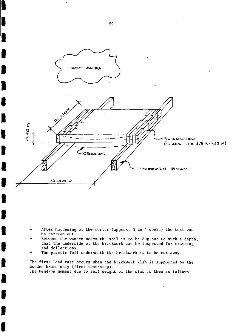
Test
To be sure that a brickwork wall has sufficient strength to carry the loadings, a test piece can be made that can be tested on failure, cracking and possible deformation. There is a relationship between tensile stresses and bending tensile stresses, whereby it may safely be assumed that the permissible tensile stress is equal to the permissible bending tensile stress.
An easy test can be carried out as described below. The working order is as follows: (see also the drawing).
A suitable area is chosen. '"Two wooden straight beams are dug into the top soil with a core to core distance of 2.0 metre. The surface is levelled. The top of the levelled surface and the wooden beams are covered with plastic foil. A 220 mm thick wall of 1.10 metre height and approx. 2.3 m in length is made on top of the plastic foil and supported by the two wooden beams (the total weight of the brick wall is approx. 1000 kg). The bricks and the mortar should be the same as those used for the watertank to be executed. The brickwork bond is indicated on the drawing below (the stretcher joints run vertically over the 1.10 m height to enable the most critical situation to be simulated).
* The brickwork wall can also be made on top of a temporary shuttering to be constructed. After hardening of the mortar the shuttering is to be removed from underneath the brickwork, with the exception of two supports.core to core 2.0 metre.
59
S C t <= K W O R K G^rz.E'C I , | x. -2 ,3 X.<=>,22 M )
V / c w & E K & E ^ N |
After hardening of the mortar (approx. 3 to 4 weeks) the test can be carried out. Between the wooden beams the soil is to be dug out to such a depth, that the underside of the brickwork can be inspected for cracking and deflections. The plastic foil underneath the brickwork is to be cut away.
The first load case occurs when the brickwork slab is supported by the wooden beams only (first test-step). The bending moment due to self weight of the slab is then as follows:

60
O.lfeM
<=\ fef?.>^K.v*'«»(*-K
^ M i 4 4 4+ 4 4|
• 2 . o « M
O , I & H
g brickwork = 4 KN/m1
( to be checked)
M = | * 4 * 2 2 = 2 KNm/m
W = \ * 1 * 0 .22 2 = 0.0081 m3
2*106
a bending moment = _ OQ»i*ioa = °• 2469N/mm2
with a load f ac to r of y = 2.5
0.2469 a pe rmiss ib l e = 2.5 = 0.099 N/mm2 (2 0.1)
* For symbols see annex IV.
This is approximately the calculated bending tensile stress on the watertank filled with water. This means that when no cracks occur in the above load case, the wall is strong enough and construction of the watertank can start. To obtain more information about the behaviour of the wall it would be interesting to load "the brickwork slab" until failure occurs. Such a test could be carried out by loading the slab step by step with a uniform load of cement bags. After each loading step it is necessary to note all changes like cracks, deflection as well as crack widths (a safety coefficient can be calculated with the formula:
_ Q bending moment Y 0.1

\
61
2.5. General starting points for the structural calculations (For symbols see annex IV)
To calculate the ring forces and the bending moments in the irrigation tanks the cylinder theory has been used a.o. according to: "Theorie und Berechnung rotations-symmetrischer Bauwerke" by Dr. Gyula Markus Where applicable, tables and coefficients from this book are added. With the above theory the following formulaa are used:
- / 3 ( 1 - M 2 ) ah
NQ = pa FN My = pah —
////////
V
////// /r F~\
h
h h w
P w
= Radius of the tank = The max. water height = wall thickness = water pressure on the bottom of the tank
Since less is known with respect to the quality of the bricks and the mortar, the stresses in the masonry should be limited: a. Where horizontal or vertical reinforcement is to be used the
tensile or bending stresses must not exceed 0.15 N/mm2. b. Where the tank will be executed without any reinforcement the
tensile or bending stresses must not exceed 0.10 N/mm2.

62
Where possible, a sample of a wall should first be made and tested. The method of testing the interpretation of the results obtained, is described in Chapter 2.4.
The wall should be made not less than 220 mm thick. To reduce cracking it is important to execute the wall in a masonry bond as indicated on the drawings. Furthermore, shrinkage and cracking can be prevented by raising the ground around the perimeter of the irrigation tank to a level of approximately 800 mm below the rim level of the tank wall. In particular the connection between the bottom slab and the wall should be carried out, very carefully in a masonry bond as indicated to protect the tank against too much leakage. Irrigation tanks with capacities of 30, 60, 90 and 150 m3 are calculated and drawn in 5 types. Type I : a fully brickwork tank, walls and slabs, without a
bund earth wall. Type II : same as type I but with a bund earth wall. Type III : brickwork ring foundation with a bund earth wall.
The remaining slab will be made of clay (impermeable soil).
Type IV : as type III but with a different foundation of the brickwork ring.
Type V : as type III or IV but with tie rods made of steel strips and without a bund earth wall.

63
2.5.1. Calculation of the tanks
Type 1 and 2 with a monolithic bottom slab in brickwork or concrete
2.5.1.1. Tank capacity of 30 m3
ah
l a l ^ M
"? 1—
1
a hw M
pa
= = = =
= pah =
J i
A —
O.l
o/2 0,3
°t 0,3 0,6>
°<7 o<& Of)
to
A
1.25 m 2.77 m 0.22 m 0.2
10*1.25*2
No. *_ A VZ | 6 < 2 O
11 = 34.6 7.62
• ._ it ,/•*? ~ | i ; '<«-
>i/d>9
\%hA \4,Gx* C2,6o
1-2, i £ 11,13
<5,aa 6&&
/ 2., 6 6
O
K = yv 3d-o.2^) = 67
2.77*0.22
Kl = 1.67 * 1.25 = 2.09
N Q
My
pa F r n
u F M
Pan "w
NQ (KN/m')
. _ 12.6-no3 _ .... 2
Au = —rr?; =115 mm* h 110
M (KNm/m')
. 0.54*106 cc. 2 A = HA i m — = 55 mm'1 v 90x110
a brickwork (h) = ^ A ^ S o = 0.0573 N/mra2 (< 0.10)
a brickwork (v) =
220-1000
0.54 *106*6 1000*220*
= 0.0669 N/mm2 (< 0.10)
-> non-reinforced, wall thickness 220 mm

64
2.5.1.2. Tank capacity of 60 m3
t->
a hw M
= = = =
1.25 m 3.91 m 0.22 m 0.2 m
K
Kl = pa = pah =
/V3 (1-02. ) = 4 V 3.91*0.22 l'w:>
1.76 10*1.25*3.91 = 48.88
= 10.75
^
NQ (KN)/ra'
. 18.79*10* ,,n 2
\ = — n o 17° ™
M (KNn)/m'
A = 0.62*106 ,„ 2 V 90* 100 = 62 ^
18 79*103 r̂ ---
a brickwork (h) = ooA-l^n = 0,085 N/mm* (< 0,10)
a brickwork (v) =
220*1000
0.62*106*6 1000*220
^ = 0,077 N/mra2 (< 0.10)
•* non-reinforced, wall thickness 220 mm

65
2.5.1.3. Tank capacity of 90 m3
1 a h
°7
1.25 ra 4.79 m 0.22/0.33 «o. 0.2
o,« 0 , 2
0 , 3
o,6
°.7
\o
A
H*<
<5 12
y A
\C 1o 1A1&
1 ) l J i j
\ \J
Ji //
V
(1-0.22) _
Kl pa pah
b v /
o,v% 0/22
z*.7* 1A& • « > . < «
T.f/24
1̂ .7 i^.a* 1 ,̂71
M , I < 5
7< 77 A,°& o
-24,11 25,6c
22,«4
tt.JJ.
16,°} IJ.2&
IS/89 \1fiS
9 , " A7* o
4.79*0.22
1.27*1.25 10*1.25*4.79
= 1.27
1.59 59.88 13.17
°7
M, °/« °.* \,i O, 3 3 o. 11.
o 0 (0-<
o,i-s o2<5 O/A
o , ^ ot63
°>r 0/Z&
o,<M
o
1
o 0 , 0 - ;
O . I 3
o,2£ 0 ,Xo
0 , « 3
o,6a O.lC
<3/S<>
o,-94 o
NQ (KN)/m'
. _ 24.11*103 oon ,. , h —flO = mm /m1
My (KNn)/m*
0.66*106
v 90*110 = 67 mm2/m 2 / m «
a brickwork (h) = 220*1000" = °-11 N/n™2 (too high)
a brickwork (v) = °ooo*220^6 = °-082 N / m m 2
-> with a wall thickness of 220 mm a tension band is to be used, e.g. a steel strip of 60*5 mm (2 strips).
*TSEi-STftipc, 0(5 T|i=RoC>«i
With a wall thickness h = 330 mm ->
K _ JfT (1-0.22) _ K " V4.79*0.33 " ^ ^ K 1 1.30

66
See
V a b
Table -*
26.78*] 110
rickwork
LO3
(h)
=
=
243
26. •3 -3r\
mm2/m'
78" •io3
nn
. _ 0.71*106 _ , , _ , / . A = i in----, in =46.0 mnr/ro v 140"110
= 0.0812 N/ram2 (< 0.10)
a brickwork (v) = °QOO*330*6 = °-039 N / m m 2 (< °-10)
-> with a wall thickness of 330 mm: "non-reinforced"

67
2 . 5 . 1 . 4 . Tank capac i ty 150 m:
1 a hw M
—
= = =
1.25 m 6.18 m 0 .33/0 .44 m 0.2
N^
K
Kl pa pahw
i t/T(i-o.2») = 0 91 6.18*0.33 *
1.14 10-1.25*6.18 = 77.25 10*1.25*6.18*0.33 = 25.49
V,^ 0.44 = 58.24 0.^.-4 Q/S5
3.772 34.1e
36,14
33,05 So . l o 17,25
i<3,<$6
\i,<yi
-4.H
^,73
i i .2-4
o
NQ (KN)/m'
. _ 36,25*103 _ 0<5„ 2 Ai. = —\TR = 330 mnr
n 110
0.44 o » 3
0
0 | 0 5
o,,<» ©,a«
o,«a
«.*9 o,<»o 0,<*2
°,7« o ^ « 0
0
0,0-4
o,l&
0, 3«»
©,.46
o,&* o , 6 9
°.7' 0 , 6 3
Ot<4o
O
My (KNn)/nT
0>71*1066
v 140*90 56 mm
68
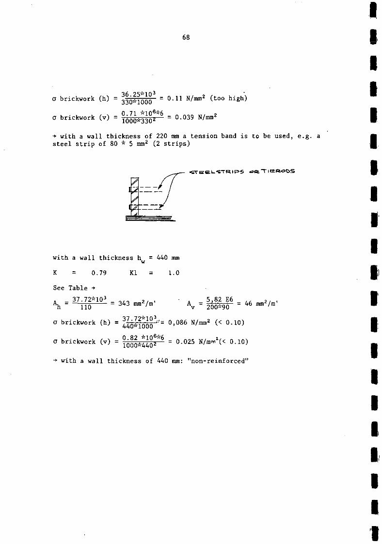
a brickwork (h) = 33Q*IQQQ =0.11 N/mm2 (too high)
a brickwork (v) = °000*330z*6 = ° - 0 3 9 N / m m 2
-> with a wall thickness of 220 mm a tension band is to be used, e.g. a steel strip of 80 * 5 mm2 (2 strips)
• C T E E L S T R I P 5 o t t T l S l l i o O S
with a wall thickness h = 440 mm w
K = 0.79 Kl = 1.0
See Table •*
. _ 37.72*103 _ „,, 2/ . " A - 5,82 E6 2 Ah " ~TTo 3 4 3 mra / m Av " 200*90 - 4 6 """ / m
a brickwork (h) = ^QIIQQQ *= 0,086 N/mm2 (< 0.10)
a brickwork (v) = ^ Q ^ ^ " 6 = 0.025 N/mmz(< 0.10)
-*• with a wall thickness of 440 mm: "non-reinforced"

69
2.5.1.5. Type III, IV and V
Ring foundation only at the bottom of the tank wall carried out in brickwork, concrete or impermeable soil
Formule:
N = 5E2 n
capacity m- hw pw NQO(n = i )
30 60 90 150
1.25 1.25 1.25 1.25
2.77 3.91 4.79 6.18
0.22 0.33 0.33 0.44
0.44 0.55 0.55 0.77
12.5 12.5 12.5 12.5
34.63 KN/m* 48.87 " 59.87 " 77.25 "

70
Calculation of hw
with CT, . . = 0.10 N/mm2 brickwork
hw = 220 mm N 330 mm 440 mm 550 mm 660 mm 770 mm
HW tt
it
It
tt
qmax = 0.10 * 220 * 1000 = 0.10 * 330 * 1000
22 KN/m' 33 44 55 66 77
In practice the above results lead to the following wall thicknesses
thickness (hw)
Tank with a capacity of 30 m3
- Top of the wall up to (T\ =
Bottom of the wall a.
22 34.63
* 1.25 = 0.80 m 220 mm
34.63E3 brickwork 1000 * 440
Tank with a capacity of 60 m3
= 0.079 N/ram2 440 mm
- Top of the wall up to *T] =
Bottom of the wall a.
33 48.87
1.25 = 0.85 m 330 mm
48.87E3 brickwork 550 * 1000
Tank with a capacity of 90 m3
= 0.089 N/mm2 550 mm
- Top of the wall up to f| = 33 59.87
* 1.25 = 0.70 m 330 mm
- Bottom of the wall a. 59.87E3 brickwork 550 * 1000
= 0.109 N/mm2 550 mm

71
Tank with a capacity of 150 m3 *) thickness
- Top of the wall up to q = yy-ojf * !-25 = 0.80 m 440 mm
77 25E3 - Bottom of the wall a, . . . = -,-,,,*.<. ,nnn = 0.10 N/mm2 770 mm
brickwork 770 * 1000 '
*) Uneconomical solution.

72
ANNEX 1
Variant* = tankwall carried out with reinforcement
non-reinforced tanks
JL = 1,-2*5 M
reinforced tanks
\f=X=> M 3
C \ 0 M 3
• * " ' — '
^ O M '
3 b M 3
/
j/7 '
/
s / / / /
/ /
f
i 1
/ /
/ /
/
'
— I 1
f-
^ o 3»»*3 -AA<=> W o MM
^^^\-\- T H I C K N E S S W
<
I
/
'Y /
/ /
/
I / I /
/
/ /
i - l^Vy. •=. *Z?.o M M
<<=>« -I- i -"2«o a>oo -Aoo *=*o<?
M M 2
t ^ e i N F O R c E M E N T
Not indicated as type in this booklet.

73
ANNEX 2
REVIEW OF THE SEVERAL TYPES
Type I II III IV V
+ more D + less -D
D
+ more + + less -++
D
D less + D more -++
+
D less + n more -++
+
+ more + + more _-D
++
water-permeability quantity materials realization durability sensity for maintenance frost-resistance resistance against changes in humidity and temperature quality of workmanship
= bad • = reasonable + = good ++ = very good

74
ANNEX 3
DESIGN TABLE
In accordance with:
Markus, "Theorie und Berechnung rotationssymmetrisscher Bauwerke"
^
\ ^ 1
1
2
3
4
5
6
7
8
I
2
3
4
5
6
7
8
0
+ 0.4883
+0 ,3518
+ 0 , 1 1 2 3
—0,0038
—0,0167
—0,0061
—0,0002
+ 0,0008
0
0
0
0
0
0
0
0
0,1
+0,4427
+ 0,3574
+0 ,2037
+0 ,1184
+ 0,0963
+0 ,0956
+0 ,0970
+0 ,0997
—0,0013
—0,0038
0,1
+0.3971
+0 ,3621
+0 ,2931
+0 ,2402
+0 ,2110
+0 ,2006
+0 ,1985
+0 ,1983
—0,0046
—0,0135
—0,0029 1 —0,0112 l
0
+ 0,0009
+0 ,0006
+ 0.0001
—0,0021
+0 ,0023
+ 0,0021
+0 ,0007
—0,0001 0
o,»
+ 0,3511
+0 ,3630
+0 ,3754
+0 ,3595
+0 ,3295
+ 0,3076
+0 ,2985
+ 0,2971
—0,0090
—0,0271
—0,0244
—0,0078
+0 ,0021
+ 0,0037
+ 0,0021
+0 ,0007
0,4
+ 0,3045
+0 ,3565
+0 ,4424
+0 ,4698
+ 0,4509
+ 0,4248
+0 ,4073
+0 ,3993
—0,0138
—0,0421
—0,0416
—0,0177
—0,0025
o.»
+0.2569
+ 0,3384
+ 0,4837
+0 ,5590
+0 ,5671
+0 ,5495
+ 0,5283
+ 0,5120
—0,0180
^0,0561
—0,0608
—0,0364
—0,0145
+0 ,0035 —0,0021
+0 ,0038
+0 ,0024
+0 ,0031
+ 0,0041
0.«
+ 0,2082
+0 .3052
+0 ,4877
+0 ,6079
+ 0,6571.
+0 .6670
+ 0 , 6 5 7 3
+0 ,6407
—0,0207
—0,0663
—0.0790
—0,0591
—0.0360
—0.0179
—0,0060
+ 0,0007
0.7
+ 0.1580
0,1
+0,1064
+ 0,2540 | +0 ,1840
+ 0,4435
+0 ,5922
+ 0,6848
+0 ,3439
+ 0,4877
+ 0.6014
+ 0,7376 1+0,6909
+ 0,7618
+ 0,7669
+0 .7581
+0 ,8059
0,(
+0,0536
+0 ,0973
+0 ,1905
+0,2829
+ 0,3677
+ 0,4471
+ 0,5202
+0 ,5870
—0,0212 1 —0,0185 1 —0,0117
—0,0695 —0,0623 —0,0405
—0,0911 1 —0,0894 i
—0,0821
—0,0651
—0,0471
—0,0309
—0,0179
—0.0942
—0,0905
—0,0822
—0,0711
—0,0591
—0,0635
1.0 '
0 ''
0
0
0
0
0
0
0
0
0
0
—0,0763 1 0
—0,0851 • 0
—0,0907
—0,0937
- 0 , 0 9 4 4
0
0
0
75
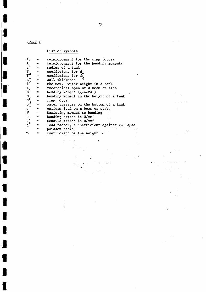
List of symbols
reinforcement for the ring forces reinforcement for the bending moments radius of a tank coefficient for M coefficient for N^ wall thickness the max. water height in a tank theoretical span of a beam or slab bending moment (general) bending moment in the height of a tank ring force water pressure on the bottom of a tank uniform load on a beam or slab. Resisting moment to bending bending stress in N/mm2
tensile stress in N/mm2
load factor, a coefficient against collapse poisson ratio ' . „ _ . . • coefficient of the height •

76
ANNEX 5
2.7. Bibliography
1. Watt S.B. Ferrocement Water Tanks London 1978
2. Markus Gyula Theorie und Berechnung rotations syrametrischer Bauwerke
3. Basic course in rural technology for gramodaya workers and leaders. Sarvodaya Shramadana Movement, Rural Technical Surveys, Colombo, 1980.
4. v. Oss J.F. Warenkennis en Technologie J.H. de Bussy 1956
5. Jellema Meischke Muller Bouwkunde Waltman 1972
6. F.W. Knipschild Stand der Technik der Abdichtung von Deponien mit HDPE
CP/JdL/MBi/JeP/S24/M