214748
DESCRIPTION
http://www.dungs.com/fileadmin/media/Downloads/DBs_BMAs/214748.pdf?1290005100TRANSCRIPT
1 … 4
Differential pressure switchfor air, flue and exhaust gases
LGW...A1
factory-adjusted
5.12
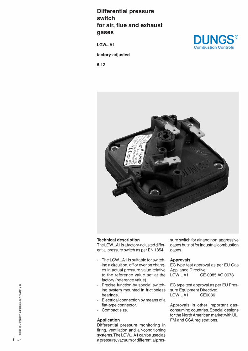
Technical descriptionThe LGW...A1 is a factory-adjusted differ-ential pressure switch as per EN 1854.
- The LGW...A1 is suitable for switch-ing a circuit on, off or over on chang-es in actual pressure value relative to the reference value set at the factory (reference value).
- Precise function by special switch-ing system mounted in frictionless bearings.
- Electrical connection by means of a flat-type connector.
- Compact size.
ApplicationDifferential pressure monitoring in firing, ventilation and air-conditioning systems. The LGW...A1 can be used as a pressure, vacuum or differential pres-
sure switch for air and non-aggressive gases but not for industrial combustion gases.
ApprovalsEC type test approval as per EU Gas Appliance Directive: LGW…A1 CE-0085 AQ 0673
EC type test approval as per EU Pres-sure Equipment Directive: LGW…A1 CE0036
Approvals in other important gas-consuming countries. Special designs for the North American market with UL, FM and CSA registrations.
Prin
ted
in G
erm
any
• Edi
tion
02.1
0 • N
r. 21
4 74
8

2 … 4
3
1
2
+–
+ A
B
Functional descriptionDifferential pressure switch in pressure and vacuum ranges.The differential pressure acts via the diaphragm against the force of the setting spring on the microswitch. The pressure switch operates without any auxiliary power.
LGW…A1 differential pressure switchThe control unit responds to differential pressure. If the set reference value is exceeded or undershot, the circuit is switched on, off or over.
Definition of switching difference ∆pThe switching difference ∆p is the pressure difference between the up-per and lower switching pressures.
Pressureat meter
Fallin
g
Setting toleranceUpper switchingpressure
Lower switchingpressure
Adju
stm
ent a
spr
essu
re fa
lls
Risin
g
LGW…A1 switching functionAs pressure rises:1 NC opens, 2 NO closesAs pressure falls:1 NC closes, 2 NO opens
COMNO2
p
3 (P)NC1
Dimensions [mm]
Pressure connection
Connection p1 (+)= higher pressureConnection p2 (-)= lower pressure
OptionalConnection p3 (+)= higher pressure
�
�
����
����
�����
�������
�����
���
���
����
�
��
��
�
�
���
�����
��
�
�
���
���
�
�
����
��
����
�
���� �
����
������������
���
���
����
� �
�
��������
Height with BS1/BS2 contact protection: 34.2 mmHeight with cover IP 40: 35.6 mmHeight with cover IP 42: 45.6 mm
3 … 4
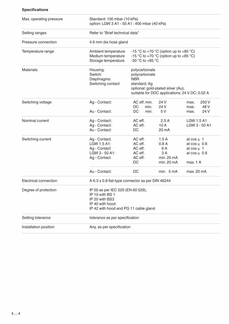
Standard: 100 mbar (10 kPa)option: LGW 3 A1 - 50 A1 : 400 mbar (40 kPa)
Refer to "Brief technical data"
4.6 mm dia hose gland
Ambient temperature -15 °C to +70 °C (option up to +85 °C)Medium temperature -15 °C to +70 °C (option up to +85 °C)Storage temperature -30 °C to +85 °C
Housing: polycarbonateSwitch: polycarbonateDiaphragms: NBRSwitching contact: standard: Ag optional: gold-plated silver (Au); suitable for DDC applications: 24 V DC; 0.02 A
Ag - Contact: AC eff. min. 24 V max. 250 V DC min. 24 V max. 48 VAu - Contact: DC min. 5 V max. 24 V Ag - Contact: AC eff. 2.5 A LGW 1.5 A1Ag - Contact: AC eff. 10 A LGW 3 - 50 A1Au - Contact: DC 20 mA
Ag - Contact. AC eff. 1.5 A at cos ϕ 1LGW 1.5 A1: AC eff. 0.8 A at cos ϕ 0.6Ag - Contact AC eff. 6 A at cos ϕ 1LGW 3 - 50 A1: AC eff. 3 A at cos ϕ 0.6Ag - Contact AC eff. min. 20 mA DC min. 20 mA max. 1 A
Au - Contact: DC min. 5 mA max. 20 mA
A 6.3 x 0.8 flat-type connector as per DIN 46244
IP 00 as per IEC 529 (EN 60 529),IP 10 with BS 1IP 20 with BS3IP 40 with hoodIP 42 with hood and PG 11 cable gland
tolerance as per specification
Any, as per specification
Specifications
Max. operating pressure
Setting ranges
Pressure connection
Temperature range
Materials
Switching voltage
Nominal current
Switching current
Electrical connection
Degree of protection
Setting tolerance
Installation position

4 … 4
Technical data1mbar = 100 kPa = 0.1 Pa ≈ 10 mmWS 1 Pa = 0.01 mbar ≈ 0.1 mWS
We reserve the right to make any changes in the interest of technical progress.
Differential pressure switchfor air, flue and exhaust gases
LGW ... A1
factory-adjusted
Setting range [mbar]
0.3 - 1.5
0.4 - 3
1 - 10
2.5 - 50
Order No.
as per specification
as per specification
as per specification
as per specification
230 216
230 280
230 282
230 281
230 301
224 940
Version
LGW 1.5 A1
LGW 3 A1
LGW 10 A1
LGW 50 A1
Max. operating pressure [mbar]
100
100
100
100
Switching differ-ence [mbar]
≤ 0.2
≤ 0.35
≤ 0.5
≤ 1
Head Offices and FactoryKarl Dungs GmbH & Co. KG Siemensstraße 6-10 D-73660 Urbach, GermanyTelephone +49 (0)7181-804-0Telefax +49 (0)7181-804-166
Postal addressKarl Dungs GmbH & Co. KGPostfach 12 29D-73602 Schorndorf, Germanye-mail [email protected] www.dungs.com
Accessories for pressure switch
BS1 / IP 10 contact protection
BS3 / IP 20 contact protection
Complete hood (IP 40)
Complete hood (IP 42)
Attachment plate
Additional test button, complete PT 4
Type
LGW…A1