213 digital laser sensor ls-400 series - panasonic connections and man-hours for the relay terminal...
TRANSCRIPT

213
FIBERSENSORS
LASERSENSORS
PHOTOELECTRICSENSORS
MICROPHOTOELECTRIC
SENSORS
AREASENSORS
SAFETY LIGHT CURTAINS /
SAFETY COMPONENTSPRESSURE /
FLOWSENSORS
INDUCTIVEPROXIMITY
SENSORS
PARTICULARUSE SENSORS
SENSOROPTIONS
SIMPLEWIRE-SAVING
UNITS
WIRE-SAVING SYSTEMS
MEASUREMENTSENSORS
STATIC CONTROL DEVICES
LASERMARKERS
PLC
HUMAN MACHINE INTERFACES
ENERGY MANAGEMENT
SOLUTIONS
FA COMPONENTS
MACHINE VISION SYSTEMS
UV CURING SYSTEMS
Selection Guide
Amplifier Built-in
Amplifier-separated
LS-500
LS-400
* This product complies with 21 CFR 1040.10 and 1040.11 Laser Notice No. 50, dated June 24, 2007, issued by CDRH (Center for Devices and Radiological Health) under the FDA (Food and Drug Administration).
Related Information
5 m (16.404 ft)
1 m (3.281 ft)
RF-33 RF-31
Compact reflector RF-310
RF-230
RF-330
RF-310 RF-330
30 m (98.425 ft)
7 m (22.966 ft)
A line width of approx. 240 mm 9.449 in (typical) at a 1,000 mm 39.370 in sensing distance
Long sensing range spot reflective type LS-H21-A
Long sensing range coaxial retroreflective type LS-H92
Connector typeLS-401/401P/403
Cable type (with external input)LS-401-C2 / LS-401P-C2
Coaxial retroreflective type LS-H91
Coaxial retroreflective type LS-H91-A
Amplifiers
Long sensing range line reflective type LS-H22
Class 1 type
Class 1 type
A spot size of approx. 10 × 8 mm 0.394 × 0.315 in at a 3 m 9.843 ft sensing distance (Note 2)
A spot diameter of approx. ø1 mm ø0.039 in at a 1 m 3.281 ft sensing distance (Note 1)
A line width of approx. 115 mm 4.528 in (typical) at a 500 mm 19.685 in sensing distance
Long sensing range spot reflective type LS-H21
Easy-to-use sealing-type reflective tape available Easy-to-use sealing-type reflective tape available
500 mm (19.685 in)
A spot diameter of approx. ø1 mm ø0.039 in at a 1,000 mm 39.370 in sensing distance (Note 1)
Notes: 1) The spot diameter is a typical example. The measurement values given here were determined with a center light intensity of 1/e2 (13.5 %).
2) This is the reference value from visual observation.
A spot diameter of approx. ø1 mm ø0.039 in at a 1 m 3.281 ft sensing distance (Note 1)
A spot diameter of approx. ø0.2 mm ø0.008 in at a 50 mm 1.969 in sensing distance (Note 1)
A spot diameter of approx. ø0.2 mm ø0.008 in at a 50 mm 1.969 in sensing distance (Note 1)
Digital Laser Sensor Amplifier-separated
LS-400 SERIES
User-friendly, high precisionlaser sensing!
We offer 6 types of laser sensor heads for various applications
These products are Class 2 (LS-H□-A: Class 1) laser in compliance with IEC / JIS / GB standards and FDA* regulations Do not look at the laser beam directly or through optical system such as a lens.
Conforming toFDA regulations(LS-H□F only)
Recognition(Excluding LS-403)
Certified (Some models only)
■SC-GU3 ........................................ P.971~
■About laser beam........................ P.1593~ ■Korea’s S-mark ............................. P.1602
■General terms and conditions ............. F-3
■Glossary of terms / General precautions ....... P.1549~ / P.1552~
■Selection guide ............................. P.169~
panasonic.net/id/pidsx/global
Interferenceprevention
Automaticsensitivity setting
Test input Timer Light intensitymonitor
PNP output type available
Digital Laser Sensor LS-400 SERIES 214
FIBERSENSORS
LASERSENSORS
PHOTOELECTRICSENSORS
MICROPHOTOELECTRICSENSORS
AREASENSORS
SAFETY LIGHT CURTAINS /SAFETY COMPONENTSPRESSURE / FLOWSENSORSINDUCTIVEPROXIMITYSENSORS
PARTICULARUSE SENSORS
SENSOROPTIONS
SIMPLEWIRE-SAVINGUNITS
WIRE-SAVING SYSTEMS
MEASUREMENTSENSORS
STATIC CONTROL DEVICES
LASERMARKERS
PLC
HUMAN MACHINE INTERFACES
ENERGY MANAGEMENT SOLUTIONS
FA COMPONENTS
MACHINE VISION SYSTEMS
UV CURING SYSTEMS
Selection GuideAmplifier Built-inAmplifier-separated
LS-500
LS-400
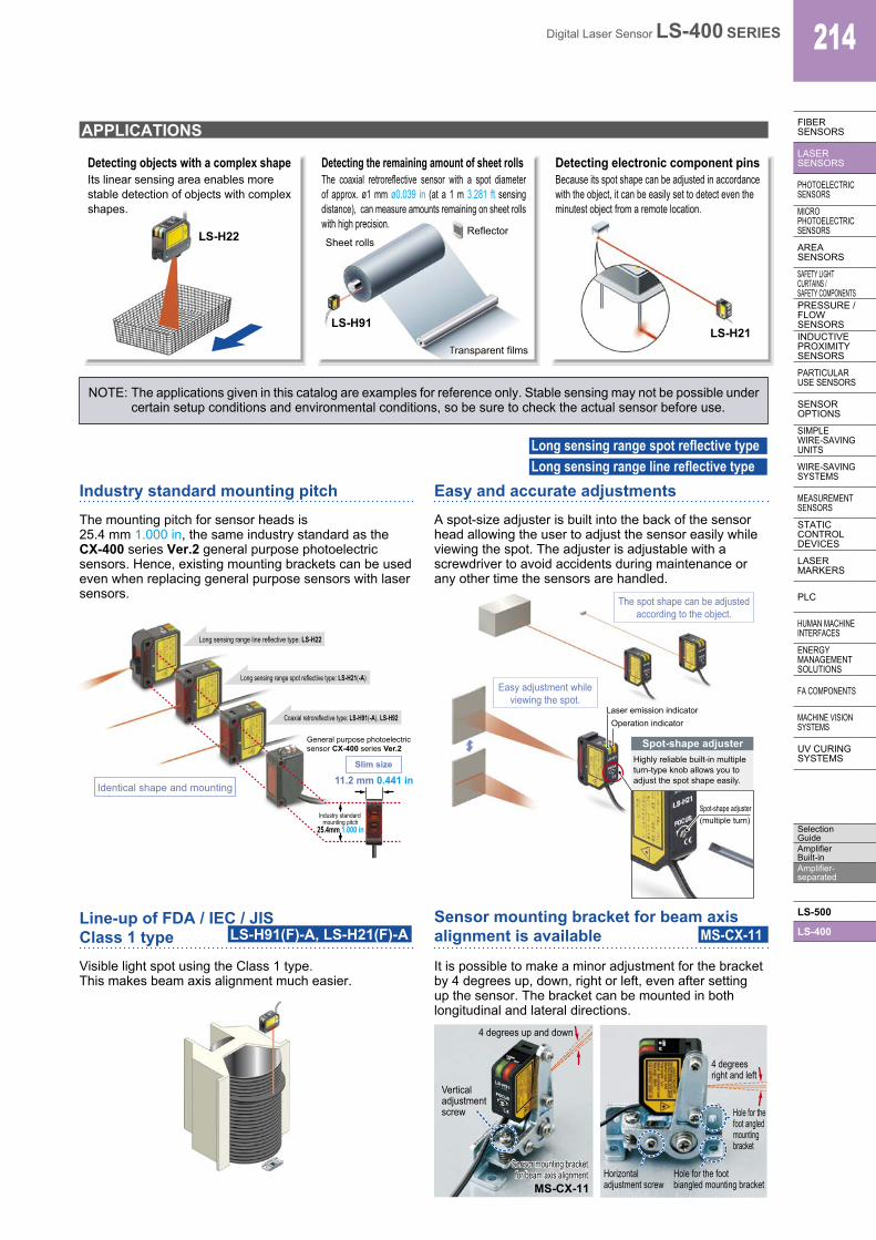
APPLICATIONS
LS-H22
Transparent films Transparent films
LS-H91
Reflector Sheet rolls
The coaxial retroreflective sensor with a spot diameter of approx. ø1 mm ø0.039 in (at a 1 m 3.281 ft sensing distance), can measure amounts remaining on sheet rolls with high precision.
LS-H21
Industry standard mounting pitchThe mounting pitch for sensor heads is 25.4 mm 1.000 in, the same industry standard as the CX-400 series Ver.2 general purpose photoelectric sensors. Hence, existing mounting brackets can be used even when replacing general purpose sensors with laser sensors.
11.2 mm 0.441 in
General purpose photoelectric sensor CX-400 series Ver.2
Long sensing range line reflective type: LS-H22
Long sensing range spot reflective type: LS-H21(-A)
Coaxial retroreflective type: LS-H91(-A), LS-H92
Industry standard mounting pitch
25.4mm 1.000 in
Identical shape and mounting
Slim size
NOTE: The applications given in this catalog are examples for reference only. Stable sensing may not be possible under certain setup conditions and environmental conditions, so be sure to check the actual sensor before use.
Operation indicator Laser emission indicator
Easy adjustment while viewing the spot.
The spot shape can be adjusted according to the object.
Spot-shape adjuster
Spot-shape adjuster(multiple turn)
Highly reliable built-in multiple turn-type knob allows you to adjust the spot shape easily.
Easy and accurate adjustmentsA spot-size adjuster is built into the back of the sensor head allowing the user to adjust the sensor easily while viewing the spot. The adjuster is adjustable with a screwdriver to avoid accidents during maintenance or any other time the sensors are handled.
Long sensing range line reflective typeLong sensing range spot reflective type
Detecting objects with a complex shape Detecting the remaining amount of sheet rolls Detecting electronic component pins
Line-up of FDA / IEC / JIS Class 1 type LS-H91(F)-A, LS-H21(F)-A
Visible light spot using the Class 1 type.This makes beam axis alignment much easier.
Sensor mounting bracket for beam axis alignment is available MS-CX-11
It is possible to make a minor adjustment for the bracket by 4 degrees up, down, right or left, even after setting up the sensor. The bracket can be mounted in both longitudinal and lateral directions.
Vertical adjustment screw
Horizontal adjustment screw
Hole for the foot angled mounting bracket
Hole for the foot biangled mounting bracket
4 degreesright and left
4 degrees up and down
MS-CX-11
Sensor mounting bracket for beam axis alignment
Sensor mounting bracket for beam axis alignment
Its linear sensing area enables more stable detection of objects with complex shapes.
Because its spot shape can be adjusted in accordance with the object, it can be easily set to detect even the minutest object from a remote location.

215 Digital Laser Sensor LS-400 SERIES
FIBERSENSORS
LASERSENSORS
PHOTOELECTRICSENSORS
MICROPHOTOELECTRIC
SENSORS
AREASENSORS
SAFETY LIGHT CURTAINS /
SAFETY COMPONENTSPRESSURE /
FLOWSENSORS
INDUCTIVEPROXIMITY
SENSORS
PARTICULARUSE SENSORS
SENSOROPTIONS
SIMPLEWIRE-SAVING
UNITS
WIRE-SAVING SYSTEMS
MEASUREMENTSENSORS
STATIC CONTROL DEVICES
LASERMARKERS
PLC
HUMAN MACHINE INTERFACES
ENERGY MANAGEMENT
SOLUTIONS
FA COMPONENTS
MACHINE VISION SYSTEMS
UV CURING SYSTEMS
Selection Guide
Amplifier Built-in
Amplifier-separated
LS-500
LS-400
Easy setting, dual displayEquipped with 2 large 4-digit digital displays. While checking the current incident light intensity (red display), the optimal threshold value (green display) can be set easily.
10 mm 0.394 in thickness
Large jog switchThreshold value setting displayGreen LED, 4 digits (Max. display: 9999)
Current incident light intensity displayRed LED, 4 digits (Max. display: 9999) Large MODE key
2 switches enable simple operationOnly two switches, the large MODE key and the large jog switch, are required for operation.
3
Pressing the switch selects or cancels the operating mode
Moving the switch from side to side allows items to be selected
Pressing the switch then confirms the selected setting
21
Threshold tracking function saves maintenance time
This function seeks changes in the light emitting amount resulting from changes in the environment over long periods (such as dust levels), so that the incident light intensity can be checked at desired intervals and the threshold values can be reset automatically. This helps to reduce the man-hours for maintenance.
Time
Current valueThe amount of lightreceived when there is no object
Inci
dent
ligh
t int
ensi
ty
Threshold value
Digital fiber sensor FX-500/300 seriesDigital pressure sensor DPS-400 series
Up to 16 units can be connected together
Note: Because the transmission method varies depending on the amplifiers, check the instruction manual for the amplifiers when connecting them.
Wiring and space saving
The quick-connection cables enable reductions in wiring. (connector type) The connections and man-hours for the relay terminal setup can be reduced and valuable space is saved. Also, LS-400 series amplifiers can of course be connected side-by-side with a connector type amplifier of FX-500/300 series digital fiber sensors or DPS-400 series digital pressure sensors.Note: Because the transmission method varies depending on the amplifiers, check the instruction manual for the amplifiers when connecting them.
*�CC-Link and CC-Link IE Field are a registered trademark of Mitsubishi Electric Corporation.DeviceNet is a registered trademark of ODVA (Open DeviceNet Vender Association, Inc.).EtherCAT is a registered trademark of Beckhoff Automation GmbH. * Refer to p.971~ for details of SC-GU3 series.
New release of type with upper communication functions to facilitate preventive maintenance!� LS-403
Network communication possibleCan connect to Open Network CC-Link IE Field / CC-Link / DeviceNet / EtherCAT via Communication Unit for Open Network SC-GU3 series. Monitoring and various settings can be done from PLC, PC, etc.
しきい値1ch
現在値90 65
2ch 50 03ch 40 704ch 0 05ch 0 06ch 0 07ch 0 08ch 0 0
しきい値9ch
現在値0 0
10ch 0 011ch 0 012ch 0 013ch 0 014ch 0 015ch 0 016ch 0 0
LS-403/501FX-501/502FX-301/305DPS-401/402
Current values of connected sensors are shown.
[Touch panel display example]Threshold values of connected sensors are shown.
End unit
Digital laser sensorDigital fiber sensorDigital fiber sensorDigital pressure sensor
Communication Unit for Open NetworkSC-GU3 series

Digital Laser Sensor LS-400 SERIES 216
FIBERSENSORS
LASERSENSORS
PHOTOELECTRICSENSORS
MICROPHOTOELECTRICSENSORS
AREASENSORS
SAFETY LIGHT CURTAINS /SAFETY COMPONENTSPRESSURE / FLOWSENSORSINDUCTIVEPROXIMITYSENSORS
PARTICULARUSE SENSORS
SENSOROPTIONS
SIMPLEWIRE-SAVINGUNITS
WIRE-SAVING SYSTEMS
MEASUREMENTSENSORS
STATIC CONTROL DEVICES
LASERMARKERS
PLC
HUMAN MACHINE INTERFACES
ENERGY MANAGEMENT SOLUTIONS
FA COMPONENTS
MACHINE VISION SYSTEMS
UV CURING SYSTEMS
Selection GuideAmplifier Built-inAmplifier-separated
LS-500
LS-400
First digit: Output operation
Second digit: Timer operation
Eighth digit: Sensing mode
Fifth digit: Hysteresis Third digit:
Response time Seventh digit:Customized function
Fourth digit: M.G.S. function
Sixth digit: External input mode
The sensitivity can be changedwithout changing the response time.
Receiving sensitivity: High
Receiving sensitivity: Medium
Receiving sensitivity: Low
By adjusting the hysteresis, convexo-concave parts of uneven objects can be cancelled enabling more stable sensing.
The sensor judges any object outside the range of incident light intensity established by two set threshold values.
Hysteresis mode Window comparator mode
By combining two outputs, wide array of control is possible, allowing you to detect meandering objects, for example.
Only rapid changes in light received are detected, which enable the edge of glass, etc. to be detected accurately. Optimal for positioning.
2 independent output modes Differential sensing mode
OK
NG: Over range
NG: Under range ON
OUT1
OFF
Incide
nt lig
ht int
ensit
y To left
To right
ON
OUT2
OFF
OK
4 new modes enabling wide array of sensing
MODE NAVI customized functionFrequently used functions such as response time, M.G.S. function, data bank load, emission halt function and D-CODE values can be stored in CUSTOM mode. The settings are changed easily.
Emission halt functionIf you do not want to place a laser spot in the visual range of the image processor, you can stop the laser radiation using the emission halt signal from the external input.
Cable type allows external inputThe LS-401-C2 cable-type amplifier is equipped with an external input wire (5-core). It is ideal to use the laser sensor at places where external teaching or laser light emission halting is to be carried out, or at the places where the laser sensor is to be used separately.
Interference prevention functionThe automatic interference prevention function prevents against interference among up to 4 sensors.
Setting conditions viewed at a glance (D-CODE)The amplifier setting is shown as an 8-digit code. Handy for remote indications and follow-ups.
Accurately sense the minutest variations (M.G.S. function)
When sensing at close range or when the target objects are transparent or minute, adjust the sensor receiving sensitivity to one of 3 levels (U-LG mode: 4 levels) for the optimal setting. In addition, changing the receiving sensitivity will not effect the response time.
CUSTOM mode
Response time
M.G.S. function
Data bank load
Emission halt function
D-CODE
2 m 6.562 ft cableattached
• Laser emission halt• Teaching
External input
217 Digital Laser Sensor LS-400 SERIES
FIBERSENSORS
LASERSENSORS
PHOTO-ELECTRICSENSORS
MICROPHOTO-
ELECTRICSENSORS
AREASENSORS
SAFETY LIGHT CURTAINS /
SAFETY COMPONENTSPRESSURE /
FLOWSENSORS
INDUCTIVEPROXIMITY
SENSORS
PARTICULARUSE
SENSORS
SENSOROPTIONS
SIMPLEWIRE-SAVING
UNITS
WIRE-SAVING SYSTEMS
MEASURE-MENT
SENSORS
STATIC CONTROL DEVICES
LASERMARKERS
PLC
HUMAN MACHINE
INTERFACES
ENERGY MANAGEMENT
SOLUTIONS
FA COMPONENTS
MACHINE VISION
SYSTEMS
UV CURING
SYSTEMS
Selection Guide
Amplifier Built-in
Amplifier-separated
LS-500
LS-400
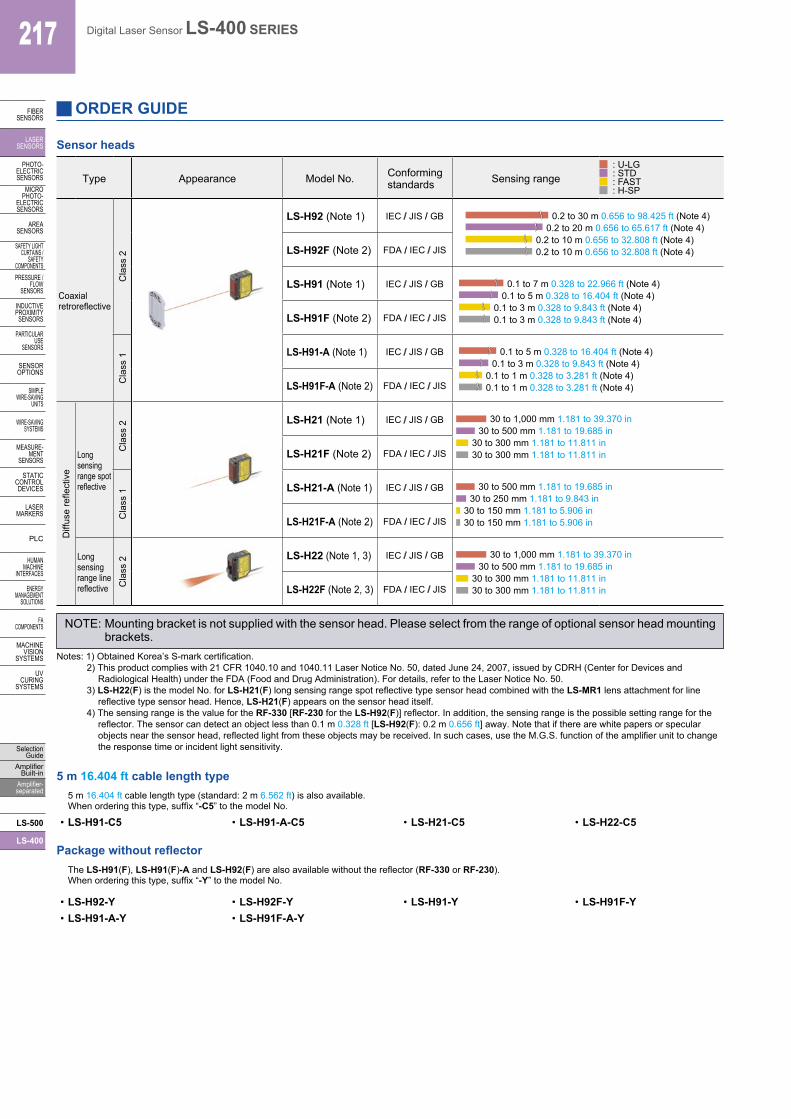
Sensor heads
Type Appearance Model No. Conformingstandards Sensing range
: U-LG: STD: FAST: H-SP
Coaxialretroreflective
Cla
ss 2
LS-H92 (Note 1) IEC / JIS / GB 0.2 to 30 m 0.656 to 98.425 ft (Note 4)0.2 to 20 m 0.656 to 65.617 ft (Note 4)
0.2 to 10 m 0.656 to 32.808 ft (Note 4)0.2 to 10 m 0.656 to 32.808 ft (Note 4)LS-H92F (Note 2) FDA / IEC / JIS
LS-H91 (Note 1) IEC / JIS / GB 0.1 to 7 m 0.328 to 22.966 ft (Note 4)0.1 to 5 m 0.328 to 16.404 ft (Note 4)
0.1 to 3 m 0.328 to 9.843 ft (Note 4)0.1 to 3 m 0.328 to 9.843 ft (Note 4)LS-H91F (Note 2) FDA / IEC / JIS
Cla
ss 1 LS-H91-A (Note 1) IEC / JIS / GB 0.1 to 5 m 0.328 to 16.404 ft (Note 4)
0.1 to 3 m 0.328 to 9.843 ft (Note 4)0.1 to 1 m 0.328 to 3.281 ft (Note 4)0.1 to 1 m 0.328 to 3.281 ft (Note 4)LS-H91F-A (Note 2) FDA / IEC / JIS
Diff
use
refle
ctiv
e
Long sensingrange spotreflective
Cla
ss 2 LS-H21 (Note 1) IEC / JIS / GB 30 to 1,000 mm 1.181 to 39.370 in
30 to 500 mm 1.181 to 19.685 in30 to 300 mm 1.181 to 11.811 in30 to 300 mm 1.181 to 11.811 inLS-H21F (Note 2) FDA / IEC / JIS
Cla
ss 1 LS-H21-A (Note 1) IEC / JIS / GB 30 to 500 mm 1.181 to 19.685 in
30 to 250 mm 1.181 to 9.843 in30 to 150 mm 1.181 to 5.906 in30 to 150 mm 1.181 to 5.906 inLS-H21F-A (Note 2) FDA / IEC / JIS
Long sensingrange linereflective C
lass
2 LS-H22 (Note 1, 3) IEC / JIS / GB 30 to 1,000 mm 1.181 to 39.370 in30 to 500 mm 1.181 to 19.685 in
30 to 300 mm 1.181 to 11.811 in30 to 300 mm 1.181 to 11.811 inLS-H22F (Note 2, 3) FDA / IEC / JIS
NOTE: Mounting bracket is not supplied with the sensor head. Please select from the range of optional sensor head mounting brackets.
Notes: 1) Obtained Korea’s S-mark certification. 2) This product complies with 21 CFR 1040.10 and 1040.11 Laser Notice No. 50, dated June 24, 2007, issued by CDRH (Center for Devices and
Radiological Health) under the FDA (Food and Drug Administration). For details, refer to the Laser Notice No. 50.3) LS-H22(F) is the model No. for LS-H21(F) long sensing range spot reflective type sensor head combined with the LS-MR1 lens attachment for line
reflective type sensor head. Hence, LS-H21(F) appears on the sensor head itself.4) The sensing range is the value for the RF-330 [RF-230 for the LS-H92(F)] reflector. In addition, the sensing range is the possible setting range for the
reflector. The sensor can detect an object less than 0.1 m 0.328 ft [LS-H92(F): 0.2 m 0.656 ft] away. Note that if there are white papers or specular objects near the sensor head, reflected light from these objects may be received. In such cases, use the M.G.S. function of the amplifier unit to change the response time or incident light sensitivity.
5 m 16.404 ft cable length type5 m 16.404 ft cable length type (standard: 2 m 6.562 ft) is also available. When ordering this type, suffix “-C5” to the model No.
• LS-H91-C5 • LS-H91-A-C5 • LS-H21-C5 • LS-H22-C5
Package without reflectorThe LS-H91(F), LS-H91(F)-A and LS-H92(F) are also available without the reflector (RF-330 or RF-230).When ordering this type, suffix “-Y” to the model No.
• LS-H92-Y • LS-H92F-Y • LS-H91-Y • LS-H91F-Y• LS-H91-A-Y • LS-H91F-A-Y
ORDER GUIDE

218Digital Laser Sensor LS-400 SERIES
FIBERSENSORS
LASERSENSORS
PHOTO-ELECTRICSENSORSMICROPHOTO-ELECTRICSENSORS
AREASENSORS
SAFETY LIGHT CURTAINS /SAFETY COMPONENTSPRESSURE / FLOWSENSORS
INDUCTIVEPROXIMITYSENSORS
PARTICULARUSE SENSORS
SENSOROPTIONS
SIMPLEWIRE-SAVINGUNITS
WIRE-SAVING SYSTEMS
MEASURE-MENTSENSORS
STATIC CONTROL DEVICES
LASERMARKERS
PLC
HUMAN MACHINE INTERFACES
ENERGY MANAGEMENT SOLUTIONS
FA COMPONENTS
MACHINE VISION SYSTEMS
UV CURING SYSTEMS
Selection GuideAmplifier Built-inAmplifier-separated
LS-500
LS-400
ORDER GUIDEAmplifiers
Type Appearance Model No. Output Connection method
Connector type
LS-401 (Note 1) NPN open-collectortransistor two outputs
Use quick-connection cable (4-core) (optional)LS-401P PNP open-collectortransistor two outputs
With upper communication function (Note 2)
LS-403 NPN open-collectortransistor two outputs
Cable type(With external input)
LS-401-C2 (Note 1) NPN open-collectortransistor two outputs
2 m 6.562 ft cabtyre cable (5-core) included Cable outer diameter: ø3.7 mm ø0.146 in
LS-401P-C2 PNP open-collectortransistor two outputs
Quick-connection cables Quick-connection cable is not supplied with the connector type amplifier. Please order it separately.
Type Appearance Model No. Description
Main cable(4-core)
CN-74-C1 Length: 1 m 3.281 ft
0.2 mm2 4-core cabtyre cable,with connector on one endCable outer diameter: ø3.3 mm ø0.130 in
CN-74-C2 Length: 2 m 6.562 ft
CN-74-C5 Length: 5 m 16.404 ft
Sub cable(2-core)
CN-72-C1 Length: 1 m 3.281 ft
0.2 mm2 2-core cabtyre cable,with connector on one endCable outer diameter: ø3.3 mm ø0.130 in
CN-72-C2 Length: 2 m 6.562 ft
CN-72-C5 Length: 5 m 16.404 ft
End plates End plates are not supplied with the amplifier. Please order them separately when the amplifiers are mounted in cascade.
Type Model No. Description
MS-DIN-E
When cascading multiple amplifiers, or when it moves depending on the way it is installed on a DIN rail, these end plates clamp amplifiers into place on both sides. Make sure to use end plates when cascading multiple amplifiers together.Two pcs. per set
Accessories• RF-330 (Reflector) • CN-EP1 (Connector for amplifier)
5 pcs. per set (Note)• LS-MR1 (Lens attachment for line reflective type)
Note: One is attached to each sensor head according to standard.
• RF-230 (Reflector)
Note: LS-H92(F) only
Notes: 1) Obtained Korea’s S-mark certification. 2) For upper communication, a communication unit for open network SC-GU3 series is needed separately. Refer to p.971~ for SC-GU3 series.

219 Digital Laser Sensor LS-400 SERIES
FIBERSENSORS
LASERSENSORS
PHOTO-ELECTRICSENSORS
MICROPHOTO-
ELECTRICSENSORS
AREASENSORS
SAFETY LIGHT CURTAINS /
SAFETY COMPONENTSPRESSURE /
FLOWSENSORS
INDUCTIVEPROXIMITY
SENSORS
PARTICULARUSE
SENSORS
SENSOROPTIONS
SIMPLEWIRE-SAVING
UNITS
WIRE-SAVING SYSTEMS
MEASURE-MENT
SENSORS
STATIC CONTROL DEVICES
LASERMARKERS
PLC
HUMAN MACHINE
INTERFACES
ENERGY MANAGEMENT
SOLUTIONS
FA COMPONENTS
MACHINE VISION
SYSTEMS
UV CURING
SYSTEMS
Selection Guide
Amplifier Built-in
Amplifier-separated
LS-500
LS-400
Designation Model No. Description
Sensor head mounting bracket
MS-CX-1 Foot angled mounting bracket
MS-CX-2 Foot biangled mounting bracketFlat mounting possible to avoid obstructions caused by the height of the sensor.
MS-CX-3 Back angled mounting bracket
MS-CX-4 Protective mounting bracketProtects sensors preventing beam axis displacement due to shocks.
Sensor mounting bracket for beam axis alignment
MS-CX-11Mounting bracket that makes fine beam axis alignment possible after setting the sensor head.Adjustment angle: up and down, right and left: 4 degreesMounting directions: two directions, vertical and horizontal
Universal sensor mounting stand(Note 1)
MS-AJ1 Horizontal mounting typeBasic assembly
MS-AJ2 Vertical mounting type
MS-AJ1-A Horizontal mounting typeLateral arm assembly
MS-AJ2-A Vertical mounting type
Amplifier mounting bracket MS-DIN-2 Mounting bracket for amplifier
Reflector mounting bracket MS-RF23 Mounting bracket for RF-230
Amplifier protection seal FX-MB1
10 sets of 2 communication window seals and 1 connector sealCommunication window seal: It prevents malfunction due to transmission signal from another
amplifier, as well as, prevents effect on another amplifier.Connector seal: It prevents contact of any metal, etc., with the pins
of the quick-connection cable.
Reflector RF-310 For coaxial retroreflective typeCompact reflector
Sensing range (U-LG mode)• LS-H91(F): 0.1 to 7 m
0.328 to 22.966 ft• LS-H91(F)-A: 0.1 to 5 m
0.328 to 16.404 ftReflective tape
RF-33For coaxial retroreflective typeSize: 25.2 × 27.8 × t 0.4 mm
0.992 × 1.094 × t 0.016 in
RF-31For coaxial retroreflective typeSize: 9.2 × 9.2 × t 0.4 mm
0.362 × 0.362 × t 0.016 in
Bank selection unit(Note 2)
FX-CH NPN input typeSetting for up to 16 laser sensors can be changed at once by means of external signals.
FX-CH-P PNP input type
Sensor head mounting bracket• MS-CX-1 • MS-CX-2
Two M3 (length 12 mm 0.472 in) screws with washers are attached.
Two M3 (length 12 mm 0.472 in) screws with washers are attached.
Notes: 1) Refer to p.953~ for the universal sensor mounting stand MS-AJ series.2) Refer to p.166 for the bank selection unit FX-CH.
Universal sensor mounting stand
45°
45° Elevation angle: ±45°
Swivel: 360° rotation
Mounting holefor M6 screw
Heightadjustment:150 mm5.906 inapprox.
• MS-AJ1 • MS-AJ1-A
45° 45°
Angle adjustment: ±45°
Swivel: 360° rotation
Mounting hole for M6 screw
360°
With the lateral arm, the sensor can sense from above a production line. Forward / back adjustment 130 mm 5.118 in approx.
Heightadjustment:150 mm5.906 inapprox.
• MS-AJ2
45°
45° Elevation angle: ±45°
Mounting holefor M6 screw
Heightadjustment:150 mm5.906 inapprox.
Swivel: 360° rotation
• MS-AJ2-A
360°
45° 45°
Angle adjustment: ±45°
With the lateral arm, the sensor can sense from above a production line.
Swivel: 360° rotation
Mounting hole for M6 screw
Forward / back adjustment 130 mm 5.118 in approx.
Heightadjustment:150 mm5.906 inapprox.
Reflector• RF-310
24 mm0.945 in
12 mm0.472 in
4 mm0.157 in
Reflective tape• RF-33
27.8 mm1.094 in0.4 mm
0.016 in 25.2 mm0.992 in
• RF-319.2 mm0.362 in
0.4 mm0.016 in 9.2 mm
0.362 in
OPTIONS
• MS-CX-3 • MS-CX-4
Two M3 (length 12 mm 0.472 in) screws with washers are attached.
Two M3 (length 12 mm 0.472 in) screws with washers are attached.
Sensor mounting bracket for beam axis alignment
Amplifier mounting bracket• MS-DIN-2
Reflector mounting bracket• MS-RF23
Two M4 (length 10 mm 0.394 in)screws with washers are attached.
Amplifier protection seal• FX-MB1
Communicationwindow seal
Connector seal
• MS-CX-11
Two M3 (length 14 mm 0.551 in) screws with washers are attached.
Bank selection unit• FX-CH(-P)

220Digital Laser Sensor LS-400 SERIES
FIBERSENSORS
LASERSENSORS
PHOTO-ELECTRICSENSORSMICROPHOTO-ELECTRICSENSORS
AREASENSORS
SAFETY LIGHT CURTAINS /SAFETY COMPONENTSPRESSURE / FLOWSENSORS
INDUCTIVEPROXIMITYSENSORS
PARTICULARUSE SENSORS
SENSOROPTIONS
SIMPLEWIRE-SAVINGUNITS
WIRE-SAVING SYSTEMS
MEASURE-MENTSENSORS
STATIC CONTROL DEVICES
LASERMARKERS
PLC
HUMAN MACHINE INTERFACES
ENERGY MANAGEMENT SOLUTIONS
FA COMPONENTS
MACHINE VISION SYSTEMS
UV CURING SYSTEMS
Selection GuideAmplifier Built-inAmplifier-separated
LS-500
LS-400
SPECIFICATIONS
Sensor heads
Notes: 1) Where measurement conditions have not been specified precisely, the conditions used were an ambient temperature of +23 °C +73.4 °F.2) This product complies with 21 CFR 1040.10 and 1040.11 Laser Notice No. 50, dated June 24, 2007, issued by CDRH (Center for Devices and
Radiological Health) under the FDA (Food and Drug Administration). For details, refer to the Laser Notice No. 50.3) LS-H22(F) is the set model No. for LS-H21(F) long sensing range spot reflective type sensor head combined with the LS-MR1 lens attachment for line
reflective type. Hence, LS-H21(F) appears on the sensor head itself.4) The sensing range is the value for the RF-330 [RF-230 for the LS-H92(F)] reflector. In addition, the sensing range is the possible setting range for the
reflector. The sensor can detect an object less than 0.1 m 0.328 ft [LS-H92(F): 0.2 m 0.656 ft] away. Note that if there are white papers or specular objects near the sensor head, reflected light from these objects may be received. In such cases, use the M.G.S. function of the amplifier unit to change the response time or incident light sensitivity.
5) Cable cannot be extended.
Type
Coaxial retroreflective Diffuse reflective
Class 2 Class 1Long sensing range spot reflective Long sensing range
line reflectiveClass 2 Class 1
Mod
el N
o. IEC / JIS / GB standards conforming type LS-H92 LS-H91 LS-H91-A LS-H21 LS-H21-A LS-H22(Note 3)
ItemFDA (Note 2) / IEC / JIS standards conforming type LS-H92F LS-H91F LS-H91F-A LS-H21F LS-H21F-A LS-H22F(Note 3)
CE marking directive compliance EMC Directive, RoHS Directive
Applicable amplifiers LS-401(P), LS-401(P)-C2, LS-403
Sen
sing
rang
e U-LG mode 0.2 to 30 m0.656 to 98.425 ft (Note 4)
0.1 to 7 m0.328 to 22.966 ft (Note 4)
0.1 to 5 m0.328 to 16.404 ft (Note 4)
30 to 1,000 mm1.181 to 39.370 in
30 to 500 mm1.181 to 19.685 in
30 to 1,000 mm1.181 to 39.370 in
STD mode 0.2 to 20 m0.656 to 65.617 ft (Note 4)
0.1 to 5 m0.328 to 16.404 ft (Note 4)
0.1 to 3 m0.328 to 9.843 ft (Note 4)
30 to 500 mm1.181 to 19.685 in
30 to 250 mm1.181 to 9.843 in
30 to 500 mm1.181 to 19.685 in
FAST mode 0.2 to 10 m0.656 to 32.808 ft (Note 4)
0.1 to 3 m0.328 to 9.843 ft (Note 4)
0.1 to 1 m0.328 to 3.281 ft (Note 4)
30 to 300 mm1.181 to 11.811 in
30 to 150 mm1.181 to 5.906 in
30 to 300 mm1.181 to 11.811 inH-SP mode
Operation indicator Orange LED (lights up when the amplifier output is ON)
Laser emission indicator Green LED (lights up during laser emission)
Spot-shape adjuster – Multi-turn adjuster
Env
ironm
enta
l res
ista
nce
Protection IP40 (IEC)
Ambient temperature –10 to +55 °C +14 to +131 °F (No dew condensation or icing allowed), Storage: –20 to +70 °C –4 to +158 °F
Ambient humidity 35 to 85 % RH, Storage: 35 to 85 % RH
Ambient illuminance Incandescent light: 3,000 ℓx or less at the light-receiving face
Voltage withstandability 1,000 V AC for one min. between all supply terminals connected together and enclosure
Insulation resistance 20 MΩ, or more, with 250 V DC megger between all supply terminals connected together and enclosure
Vibration resistance 10 to 500 Hz frequency, 1.5 mm 0.059 in (10 G max.) double amplitude in X, Y and Z directions for two hours each
Shock resistance 100 m/s2 acceleration (10 G approx.) in X, Y and Z directions three times each
Em
ittin
g el
emen
t IEC / JIS / GB standardsconforming type
Red semiconductor laser,Class 2 (IEC / JIS / GB)
Max. output: 3 mWPeak emission wavelength: 655 nm 0.026 mil
Red semiconductor laser,Class 1 (IEC / JIS / GB)
Max. output: 1 mWPeak emission wavelength:655 nm 0.026 mil
Red semiconductor laser,Class 2 (IEC / JIS / GB)
Max. output: 3 mWPeak emission wavelength:655 nm 0.026 mil
Red semiconductor laser,Class 1 (IEC / JIS / GB)
Max. output: 1 mWPeak emission wavelength:655 nm 0.026 mil
Red semiconductor laser,Class 2 (IEC / JIS / GB)
Max. output: 3 mWPeak emission wavelength:655 nm 0.026 mil
FDA (Note 2) / IEC / JIS standardsconforming type
Red semiconductor laser,Class 2 (FDA / IEC / JIS)
Max. output: 3 mWPeak emission wavelength: 655 nm 0.026 mil
Red semiconductor laser,Class 1 (FDA / IEC / JIS)
Max. output: 1 mWPeak emission wavelength:655 nm 0.026 mil
Red semiconductor laser,Class 2 (FDA / IEC / JIS)
Max. output: 3 mWPeak emission wavelength:655 nm 0.026 mil
Red semiconductor laser,Class 1 (FDA / IEC / JIS)
Max. output: 1 mWPeak emission wavelength:655 nm 0.026 mil
Red semiconductor laser,Class 2 (FDA / IEC / JIS)
Max. output: 3 mWPeak emission wavelength:655 nm 0.026 mil
Material Enclosure: PBT (Mounting part: PEI), Lens cover: Acrylic
Cable 0.1 mm2, single core two parallel shielded cables, 2 m 6.562 ft long (Connector for amplifier attached) (Note 5)
Weight Net weight: 30 g approx.Gross weight: 40 g approx.
Net weight: 30 g approx.Gross weight: 45 g approx.
Net weight: 30 g approx.Gross weight: 40 g approx.
Net weight: 35 g approx.Gross weight: 45 g approx.
Accessories
RF-230(Reflector):1 pc.
Warning label: 1 setLabels are written in Japanese, English and Chinese for compliance with various standards.
RF-330(Reflector):1 pc.
Warning label: 1 setLabels are written in Japanese, English and Chinese for compliance with various standards.
RF-330(Reflector):1 pc.
Explanation label: 1 setLabels are written in Japanese and Chinese for compliance with various standards.
Warning label: 1 setLabels are written in Japanese, English and Chinese for compliance with various standards.
Explanation label: 1 setLabels are written in Japanese and Chinese for compliance with various standards.
LS-MR1Lens attachmentfor line reflective : 1 pc.
Warning label: 1 setLabels are written in Japanese, English and Chinese for compliance with various standards.
221 Digital Laser Sensor LS-400 SERIES
FIBERSENSORS
LASERSENSORS
PHOTO-ELECTRICSENSORS
MICROPHOTO-
ELECTRICSENSORS
AREASENSORS
SAFETY LIGHT CURTAINS /
SAFETY COMPONENTSPRESSURE /
FLOWSENSORS
INDUCTIVEPROXIMITY
SENSORS
PARTICULARUSE
SENSORS
SENSOROPTIONS
SIMPLEWIRE-SAVING
UNITS
WIRE-SAVING SYSTEMS
MEASURE-MENT
SENSORS
STATIC CONTROL DEVICES
LASERMARKERS
PLC
HUMAN MACHINE
INTERFACES
ENERGY MANAGEMENT
SOLUTIONS
FA COMPONENTS
MACHINE VISION
SYSTEMS
UV CURING
SYSTEMS
Selection Guide
Amplifier Built-in
Amplifier-separated
LS-500
LS-400
SPECIFICATIONS
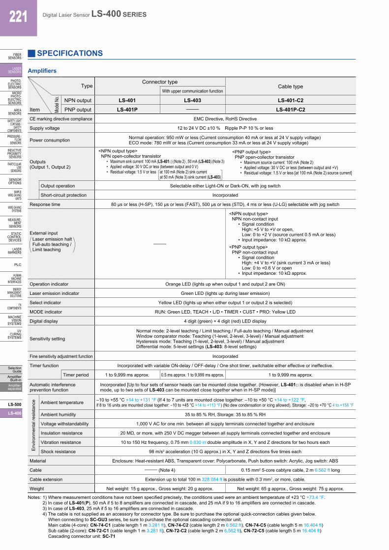
Amplifiers
TypeConnector type
Cable typeWith upper communication function
Mode
l No. NPN output LS-401 LS-403 LS-401-C2
Item PNP output LS-401P – LS-401P-C2CE marking directive compliance EMC Directive, RoHS Directive
Supply voltage 12 to 24 V DC ±10 % Ripple P-P 10 % or less
Power consumption Normal operation: 950 mW or less (Current consumption 40 mA or less at 24 V supply voltage)ECO mode: 780 mW or less (Current consumption 33 mA or less at 24 V supply voltage)
Outputs(Output 1, Output 2)
<NPN output type>NPN open-collector transistor
• Maximum sink current: 100 mA (LS-401□) (Note 2) , 50 mA (LS-403) (Note 3)• Applied voltage: 30 V DC or less (between output and 0 V)• Residual voltage: 1.5 V or less at 100 mA (Note 2) sink current
at 50 mA (Note 3) sink current (LS-403)
<PNP output type>PNP open-collector transistor
• Maximum source current: 100 mA (Note 2)• Applied voltage: 30 V DC or less (between output and +V)• Residual voltage: 1.5 V or less [at 100 mA (Note 2) source current]
Output operation Selectable either Light-ON or Dark-ON, with jog switch
Short-circuit protection Incorporated
Response time 80 µs or less (H-SP), 150 µs or less (FAST), 500 µs or less (STD), 4 ms or less (U-LG) selectable with jog switch
External inputLaser emission haltFull-auto teaching /Limit teaching
–
<NPN output type>NPN non-contact input
• Signal condition High: +5 V to +V or open, Low: 0 to +2 V (source current 0.5 mA or less)
• Input impedance: 10 kΩ approx.<PNP output type>
PNP non-contact input• Signal condition
High: +4 V to +V (sink current 3 mA or less) Low: 0 to +0.6 V or open
• Input impedance: 10 kΩ approx.
Operation indicator Orange LED (lights up when output 1 and output 2 are ON)
Laser emission indicator Green LED (lights up during laser emission)
Select indicator Yellow LED (lights up when either output 1 or output 2 is selected)
MODE indicator RUN: Green LED, TEACH • L/D • TIMER • CUST • PRO: Yellow LED
Digital display 4 digit (green) + 4 digit (red) LED display
Sensitivity setting
Normal mode: 2-level teaching / Limit teaching / Full-auto teaching / Manual adjustmentWindow comparator mode: Teaching (1-level, 2-level, 3-level) / Manual adjustmentHysteresis mode: Teaching (1-level, 2-level, 3-level) / Manual adjustmentDifferential mode: 5-level settings (LS-403: 8-level settings)
Fine sensitivity adjustment function Incorporated
Timer function Incorporated with variable ON-delay / OFF-delay / One shot timer, switchable either effective or ineffective.
Timer period 1 to 9,999 ms approx. 0.5 ms approx. 1 to 9,999 ms approx. 1 to 9,999 ms approx.
Automatic interference prevention function
Incorporated [Up to four sets of sensor heads can be mounted close together. (However, LS-401□ is disabled when in H-SP mode, up to two sets of LS-403 can be mounted close together when in H-SP mode)]
Env
ironm
enta
l res
ista
nce Ambient temperature –10 to +55 °C +14 to +131 °F (If 4 to 7 units are mounted close together: –10 to +50 °C +14 to +122 °F,
if 8 to 16 units are mounted close together: –10 to +45 °C +14 to +113 °F) (No dew condensation or icing allowed), Storage: –20 to +70 °C 4 to +158 °F
Ambient humidity 35 to 85 % RH, Storage: 35 to 85 % RH
Voltage withstandability 1,000 V AC for one min. between all supply terminals connected together and enclosure
Insulation resistance 20 MΩ, or more, with 250 V DC megger between all supply terminals connected together and enclosure
Vibration resistance 10 to 150 Hz frequency, 0.75 mm 0.030 in double amplitude in X, Y and Z directions for two hours each
Shock resistance 98 m/s2 acceleration (10 G approx.) in X, Y and Z directions five times each
Material Enclosure: Heat-resistant ABS, Transparent cover: Polycarbonate, Push button switch: Acrylic, Jog switch: ABS
Cable – (Note 4) 0.15 mm2 5-core cabtyre cable, 2 m 6.562 ft long
Cable extension Extension up to total 100 m 328.084 ft is possible with 0.3 mm2, or more, cable.
Weight Net weight: 15 g approx., Gross weight: 20 g approx. Net weight: 65 g approx., Gross weight: 75 g approx.
Notes: 1) Where measurement conditions have not been specified precisely, the conditions used were an ambient temperature of +23 °C +73.4 °F.2) In case of LS-401(P), 50 mA if 5 to 8 amplifiers are connected in cascade, and 25 mA if 9 to 16 amplifiers are connected in cascade.3) In case of LS-403, 25 mA if 5 to 16 amplifiers are connected in cascade.4) The cable is not supplied as an accessory for connector type. Be sure to purchase the optional quick-connection cables given below.
When connecting to SC-GU3 series, be sure to purchase the optional cascading connector unit. Main cable (4-core): CN-74-C1 (cable length 1 m 3.281 ft), CN-74-C2 (cable length 2 m 6.562 ft), CN-74-C5 (cable length 5 m 16.404 ft) Sub cable (2-core): CN-72-C1 (cable length 1 m 3.281 ft), CN-72-C2 (cable length 2 m 6.562 ft), CN-72-C5 (cable length 5 m 16.404 ft) Cascading connector unit: SC-71

222Digital Laser Sensor LS-400 SERIES
FIBERSENSORS
LASERSENSORS
PHOTO-ELECTRICSENSORSMICROPHOTO-ELECTRICSENSORS
AREASENSORS
SAFETY LIGHT CURTAINS /SAFETY COMPONENTSPRESSURE / FLOWSENSORS
INDUCTIVEPROXIMITYSENSORS
PARTICULARUSE SENSORS
SENSOROPTIONS
SIMPLEWIRE-SAVINGUNITS
WIRE-SAVING SYSTEMS
MEASURE-MENTSENSORS
STATIC CONTROL DEVICES
LASERMARKERS
PLC
HUMAN MACHINE INTERFACES
ENERGY MANAGEMENT SOLUTIONS
FA COMPONENTS
MACHINE VISION SYSTEMS
UV CURING SYSTEMS
Selection GuideAmplifier Built-inAmplifier-separated
LS-500
LS-400
I/O CIRCUIT AND WIRING DIAGRAMS
I/O circuit diagram Wiring diagram
Users’ circuitInternal circuit
D
Color code of cable type/quick-connection cable
(Brown) +V (Note 1)
(Black) Output 1
100 mA / 50 mA max. (Note 3,4)
100 mA / 50 mA max. (Note 3,4)
(White) Output 2
ZD1 ZD2
(Blue) 0 V (Note 1)
Tr1
Tr2
(Pink) External input (Note 2)
* 1
+5V
Load Load
3
4
1
2
Terminal No. of connector type
Sen
sor c
ircui
t
12 to 24V DC±10 %
+
–
12 to 24V DC±10 %
Brown (Note 1)
BlackWhite
Blue (Note 1)
Color code of cable type/quick-connection cable
Pink (Note 2)
Load Load
* 1
+
–
Notes: 1) The quick-connection sub cable does not have brown lead wire and blue lead wire.
The power is supplied from the connector of the main cable.2) The quick-connection cable does not have a pink lead wire.
Notes: 1) The quick-connection sub cable does not have +V (brown) and 0 V (blue). The power is supplied from the connector of the main cable.
2) Connector type LS-401/403 does not incorporate the external input.
3) LS-401(-C2) is 100 mA max, however, LS-401(-C2) is 50 mA max. if 5 to 8 amplifiers are connected in cascade, and 25 mA max. if 9 to 16 amplifiers are connected in cascade.
4) LS-403 is 50 mA max, however, it is 25 mA max. if 5 to 16 amplifiers are connected in cascade.
Terminal layout of connector type
+V Terminal No.
Output 1
Output 2 4
0 V
1
2
3
34
12
* Connector for amplifier (CN-EP1) pin position
Terminal No. Connection cable
1 Conductor core wire: BrownCable color: Gray
2 Shield wire
3 Conductor core wire: YellowCable color: Black
4 Shield wire
Wiring diagram
White
Blue (Note 1)
Pink (Note 2)Black
Brown (Note 1)
Color code of cable type/quick-connection cable
* 1 12 to 24V DC±10 %
Load Load
+
–
Notes: 1) The quick-connection sub cable does not have brown lead wire and blue lead wire.
The power is supplied from the connector of the main cable.2) The quick-connection cable does not have a pink lead wire.
Terminal layout of connector type
+V Terminal No.
Output 1
Output 2 4
0 V
1
2
3
* Connector for amplifier (CN-EP1) pin position
34
12
LS-401(-C2) LS-403 NPN output type
I/O circuit diagram
Users’ circuit Internal circuit
ZD1 ZD2
(Pink) External input (Note 2)
D
Tr1
Tr2
100 mA max. (Note 3)
100 mA max. (Note 3)(Black) Output 1
(Blue) 0 V (Note 1)
(White) Output 2
0V
2
4
1
3
Color code of cable type/quick-connection cableTerminal No. of connector type
(Brown) +V (Note 1)
Sen
sor c
ircui
t * 1
Load Load
12 to 24V DC±10 %
+
–
Notes: 1) The quick-connection sub cable does not have +V (brown) and 0 V (blue). The power is supplied from the connector of the main cable.
2) Connector type LS-401P does not incorporate the external input.3) LS-401P is 50 mA max. if 5 to 8 amplifiers are connected in
cascade, and 25 mA max. if 9 to 16 amplifiers are connected in cascade.
LS-401P(-C2) PNP output type
* 1
Non-voltage contact or NPN open-collector transistor
or
• External inputHigh: +5 V to +V, or openLow: 0 to +2 V (source current: 0.5 mA or less)• Beam emission halts and teaching occurs
when at Low.
Symbols … D: Reverse supply polarity protection diodeZD1, ZD2: Surge absorption zener diodeTr1, Tr2: NPN output transistor
* 1
Non-voltage contact or PNP open-collector transistor
or
• External inputHigh: +4 V to +V (sink current: 3 mA or less)Low: 0 to +0.6 V, or open• Beam emission halts and teaching occurs
when at High.
Symbols … D: Reverse supply polarity protection diodeZD1, ZD2: Surge absorption zener diodeTr1, Tr2: PNP output transistor
Terminal No. Connection cable
1 Conductor core wire: BrownCable color: Gray
2 Shield wire
3 Conductor core wire: YellowCable color: Black
4 Shield wire

223 Digital Laser Sensor LS-400 SERIES
FIBERSENSORS
LASERSENSORS
PHOTO-ELECTRICSENSORS
MICROPHOTO-
ELECTRICSENSORS
AREASENSORS
SAFETY LIGHT CURTAINS /
SAFETY COMPONENTSPRESSURE /
FLOWSENSORS
INDUCTIVEPROXIMITY
SENSORS
PARTICULARUSE
SENSORS
SENSOROPTIONS
SIMPLEWIRE-SAVING
UNITS
WIRE-SAVING SYSTEMS
MEASURE-MENT
SENSORS
STATIC CONTROL DEVICES
LASERMARKERS
PLC
HUMAN MACHINE
INTERFACES
ENERGY MANAGEMENT
SOLUTIONS
FA COMPONENTS
MACHINE VISION
SYSTEMS
UV CURING
SYSTEMS
Selection Guide
Amplifier Built-in
Amplifier-separated
LS-500
LS-400
PRECAUTIONS FOR PROPER USE
• This catalog is a guide to select a suitable product. Be sure to read the instruction manual attached to the product prior to its use.
• These products are class 2 (LS-H□-A: Class 1) laser in compliance with IEC / JIS / GB standards and FDA* regulations. Do not look at the laser beam directly or through optical system such as a lens.
• The following label is attached to the product. Handle the product according to the instruction given on the warning label.IEC / JIS / GB Class 2 type
This product has warning labels attached and included in the packaging that are written in Japanese, English and Chinese for compliance with various standards.
FDA Class 1 type
This product has explanation labels attached and included in the packaging that are written in Japanese, English and Chinese for compliance with various standards.
Cautions for laser beams
Safety standards for laser beam products• A laser beam can harm human being’s eyes, skin, etc.,
because of its high energy density. IEC has classified laser products according to the degree of hazard and the stipulated safety requirements. LS-H□(F) is classified as Class 2 laser. LS-H□(F)-A is classified as Class 1 laser.
Spot-shape adjuster (Only for LS-H21□, LS-H22□)
• The diffuse reflective type LS-H21□ and LS-H22□ incorporate the spot-shape adjuster to adjust the shape of spots.
Spot-shape adjuster Description
Turn the spot-shape adjuster clockwise or counter-clockwise to adjust the spot shape at your desired detecting distance. However, if the adjuster is turned too far, it may be damaged.
Safe use of laser products• For the purpose of preventing users from suffering
injuries by laser products, IEC 60825-1 (Safety of laser products). Please check the standards before use. (Refer to p.1593~ for information about laser beam.)
• Never use this product as a sensing device for personnel protection.
• In case of using sensing devices for personnel protection, use products which meet laws and standards, such as OSHA, ANSI or IEC etc., for personnel protection applicable in each region or country.
Classification by IEC 60825-1
Classification Description
Class 1Lasers that are safe under reasonably foreseeable conditions of operation, including the use of optical instruments for intrabeam viewing.
Class 2
Lasers that emit visible radiation in the wavelength range from 400 nm to 700 nm where eye protection is normally afforded by aversion responses, including the blink reflex.This reaction may be expected to provide adequate protection under reasonably foreseeable conditions of operation including the use of optical instruments for intrabeam viewing.
Part description (Amplifier)
1 2
2
3 1
L/D PROCUSTTIMER PUSH MODE
CANCELOUT
LASERON
Select 1 indicator (Yellow)Output 1 operation indicator (Orange)
MODE indicator / RUN (Green)
MODE indicator / TEACH (Yellow)
Digital display (Green, Red)Jog switch
MODE key
Select 2 indicator (Yellow)
Output 2 operation indicator (Orange)
MODE indicator / TIMER (Yellow)
MODE indicator / CUSTOM (Yellow)
Laser emission indicator(Green)
MODE indicator /L/D ON (Yellow)
MODE indicator /PRO (Yellow)
* This product complies with 21 CFR 1040.10 and 1040.11 Laser Notice No. 50, dated June 24, 2007, issued by CDRH (Center for Devices and Radiological Health) under the FDA (Food and Drug Administration).
Refer to p.1552~ for general precautions and p.1593~ for information about laser beam.

224Digital Laser Sensor LS-400 SERIES
FIBERSENSORS
LASERSENSORS
PHOTO-ELECTRICSENSORSMICROPHOTO-ELECTRICSENSORS
AREASENSORS
SAFETY LIGHT CURTAINS /SAFETY COMPONENTSPRESSURE / FLOWSENSORS
INDUCTIVEPROXIMITYSENSORS
PARTICULARUSE SENSORS
SENSOROPTIONS
SIMPLEWIRE-SAVINGUNITS
WIRE-SAVING SYSTEMS
MEASURE-MENTSENSORS
STATIC CONTROL DEVICES
LASERMARKERS
PLC
HUMAN MACHINE INTERFACES
ENERGY MANAGEMENT SOLUTIONS
FA COMPONENTS
MACHINE VISION SYSTEMS
UV CURING SYSTEMS
Selection GuideAmplifier Built-inAmplifier-separated
LS-500
LS-400
PRECAUTIONS FOR PROPER USE
Sensor head• The tightening torque should be 0.5 N·m or less.
M3 (length 12 mm 0.472 in) screw with washers
Sensor head mounting bracket (optional)
• When placing the sensor head horizontally or vertically, the reflector must also be positioned horizontally or vertically as shown in Fig. 1 below. If the sensor head is placed horizontally or vertically but the reflector is leaned as shown in Fig. 2 below, the reflection amount will decrease, which may cause unstable detection.
Fig. 1 Proper positioning
When placing the sensor head horizontally or vertically, the reflector shall also be positioned horizontally or vertically.
<Correct>
Fig. 2 Improper positioning
When placing the sensor head horizontally or vertically, but the reflector is leaned.
<Incorrect>
• The lens attachment for line reflective type LS-MR1 mounted in the long sensing range line reflective type LS-H22□ is removable. When LS-H22□ is used without LS-MR1, it will provide the equivalent performance to the long sensing range spot reflective type LS-H21□. In addition, the optional LS-MR1 can be attached to LS-H21□ to obtain the performance equivalent to LS-H22□.
• Keep the lens clean of dust, dirt, water, oil, grease, etc.• Do not apply any excessive force to LS-MR1.
Such force may cause damage.
2 After mounting, check that LS-MR1 is properly fixed to the sensor head.
Removing method
1 Insert a screwdriver into the fixing slot located at the top of sensor head.
2 Tilt the screwdriver inserted in Step 1 to remove LS-MR1.
Mounting method
1 The size of upper fixing hook of LS-MR1 is not same as the lower fixing hook. After identifying the upper and lower fixing hooks, insert LS-MR1 upper fixing hook into the fixing slot at the top of sensor head and then insert LS-MR1 lower fixing hook into the fixing slot at the bottom of sensor head.
Fixing slot
Fixing slot
Fixing hooks
Lens attachment forline reflective typeLS-MR1
Lens attachment for line reflective type (LS-MR1)
Others• Do not use during the initial transient time (0.5 sec. approx.)
after the power supply is switched on.• Because the sensitivity is higher in U-LG mode than in other
modes, it can be more easily affected by extraneous noise. Check the operating environment before use.
• These sensors are only for indoor use.• Avoid dust, dirt, and steam.• Take care that the product does not come in direct contact
with water, oil, grease, or organic solvents, such as, thinner, etc.
• This sensor cannot be used in an environment containing inflammable or explosive gasses.
• Never disassemble or modify the sensor.
• Make sure that the power supply is off while wiring.• Verify that the supply voltage variation is within the rating.• Take care that if a voltage exceeding the rated range is
applied, or if an AC power supply is directly connected, the sensor may get burnt or damaged.
• Take care that short-circuit or wrong wiring of the load may burn or damage the sensor.
• Do not run the wires together with high-voltage lines or power lines or put them in the same raceway. This can cause malfunction due to induction.
• Ensure that an isolation transformer is utilized for the DC power supply. If an auto transformer is utilized, the main amplifier or power supply may be damaged.
• Make sure to use the optional quick-connection cable for the connection of the amplifier [connector type LS-401(P) /LS-403]. Extension up to total 100 m 328.084 ft is possible with 0.3 mm2, or more,cable. However, in order to reduce noise, make the wiring as short as possible.
Amplifier
Mounting
<How to mount the amplifier>1 Fit the rear part of the mounting
section of the amplifier on a 35 mm 1.378 in width DIN rail.
2 Press down the rear part of the mounting section of the unit on the 35 mm 1.378 in width DIN rail and fit the front part of the mounting section to the DIN rail.
<How to remove the amplifier>1 Push the amplifier forward.2 Lift up the front part of the amplifier
to remove it.Note: Be careful. If the front part is lifted without
pushing the amplifier forward, the hook on the rear portion of the mounting section is likely to break.
<How to mount the sensor head>1 Insert the sensor head connector
into the inlet until it clicks.2 Fit the cover to the connector.
Wiring
Sensor head connector
Cover
1
2
12
2 1
35mm 1.378 in width DIN rail
Refer to p.1552~ for general precautions and p.1593~ for information about laser beam.

225 Digital Laser Sensor LS-400 SERIES
FIBERSENSORS
LASERSENSORS
PHOTO-ELECTRICSENSORS
MICROPHOTO-
ELECTRICSENSORS
AREASENSORS
SAFETY LIGHT CURTAINS /
SAFETY COMPONENTSPRESSURE /
FLOWSENSORS
INDUCTIVEPROXIMITY
SENSORS
PARTICULARUSE
SENSORS
SENSOROPTIONS
SIMPLEWIRE-SAVING
UNITS
WIRE-SAVING SYSTEMS
MEASURE-MENT
SENSORS
STATIC CONTROL DEVICES
LASERMARKERS
PLC
HUMAN MACHINE
INTERFACES
ENERGY MANAGEMENT
SOLUTIONS
FA COMPONENTS
MACHINE VISION
SYSTEMS
UV CURING
SYSTEMS
Selection Guide
Amplifier Built-in
Amplifier-separated
LS-500
LS-400
DIMENSIONS (Unit: mm in) The CAD data can be downloaded from our website.
Sensor headLS-H91(-A) LS-H91F(-A) Sensor headLS-H92 LS-H92F
( )
25 0.984
ø1.45 ø0.057, single coretwo parallel shielded cables
11.20.441
311.220
25.41.000
2-M3 × 0.5 0.020thru-hole threads
30.118
2,00078.740( )
15.50.610
50.197
Beam emitting /receiving part
CN-EP1
Laser emission indicator (Green)
Operation indicator (Orange)
(18 0.709)
160.630
CN-EP1
8.80.346
10.039
7.60.299
Laser emission indicator (Green)
Operation indicator (Orange)
( )160.630
(18 0.709)
2,00078.740( )
ø1.45 ø0.057, single coretwo parallel shielded cables
2-M3 × 0.5 0.020thru-hole threads
50.197
15.50.610
11.20.441 25
0.984 3 0.118
311.220
25.41.000Beam emitting /
receiving part
Sensor headLS-H21(-A) LS-H21F(-A) Sensor headLS-H22 LS-H22F
Beam-receivingpart
Beam-emittingpart
5 0.197
30.118
18.50.728
Spot-size adjuster
CN-EP1
Laser emission indicator (Green)
Operation indicator (Orange)
25 0.984 3
0.118
11.20.44115.5
0.610
ø1.45 ø0.057, single coretwo parallel shielded cables
2-M3 × 0.5 0.020thru-hole threads
(18 0.709)
( )160.630
2,00078.740( )
311.220
25.41.000
CN-EP1
50.197
30.118
3.50.138
1.5 0.059
33.51.319
40.157
Laser emission indicator (Green)
Operation indicator (Orange)
Spot-size adjuster
25 0.984
3 0.11811.20.441
Beam-receivingpart
Beam-emittingpart
ø1.45 ø0.057, single coretwo parallel shielded cables
2-M3 × 0.5 0.020thru-hole threads
18.50.728
18.50.72831
1.22025.41.000( )
( )
(18 0.709)
( )160.630
2,00078.740( )
AmplifierLS-401 LS-401P LS-403 AmplifierLS-401-C2 LS-401P-C2
110.433
100.394
752.953 27.8
1.094
30.118
301.181
240.945
Communication window
Suitable for 35 mm1.378 in width DIN rail
Digital display (Red, Green)
10.50.413
3.95 0.156
3 0.1183
0.11870.276
Jog switchMODE key
5.15 0.203
8.40.331 2.7 0.106
30.851.215
58.72.311
120.472
Select 1 indicator (Yellow)
Select 2 indicator (Yellow)
Output 1 operation indicator (Orange)
Laser emission indicator (Green)
Output 2 operation indicator (Orange)
36.51.437
Jog switch
Communication window
3 0.118
MODE key
ø3.7 0.146 cable, 2 m 6.562 ft long
Digital display (Red, Green)
Suitable for 35 mm 1.378 in width DIN rail
8.40.331
30.851.215
120.472
30.118
240.945
36.51.437 3.95
0.156
3 0.118
1.40.055
13.050.514
20.079
30.118
ø8ø0.315
9.20.362
100.394
110.433
10.50.413
Select 1 indicator (Yellow)Select 2 indicator (Yellow)
Output 1 operation indicator (Orange)
Laser emission indicator (Green)
Output 2 operation indicator (Orange)
58.72.311
2.7 0.1065.15 0.203
301.181
752.953 27.8
1.094
Main cable (Optional)CN-74-C1 CN-74-C2 CN-74-C5 Sub cable (Optional)CN-72-C1 CN-72-C2 CN-72-C5
ø3.3 ø0.130 cable
2.65 0.104
2.54 0.100
2.54 0.100
2.9 0.114
6 0.236
10 0.394
7.2 0.283
3 0.118
0.2 0.008 10
0.394
70.276
L 50 1.969
10.5 0.413
13.60.535
14 0.551 ( ) ( )
( )
12 0.472 ( )
• Length L
Model No. Length L
CN-74-C1 1,000 39.370
CN-74-C2 2,000 78.740
CN-74-C5 5,000 196.850
• Length L
ø3.3 ø0.130 cable3
0.118
L
2.65 0.104
2.54 0.100
2.54 0.100
2.9 0.114
6 0.236
10 0.394
7.2 0.283
3 0.118 0.2
0.008
50 1.969
14 0.551 ( )
( ) ( )
12 0.472 ( ) 10.5
0.413
100.394
70.276
13.60.535
Model No. Length L
CN-72-C1 1,000 39.370
CN-72-C2 2,000 78.740
CN-72-C5 5,000 196.850

226Digital Laser Sensor LS-400 SERIES
FIBERSENSORS
LASERSENSORS
PHOTO-ELECTRICSENSORSMICROPHOTO-ELECTRICSENSORS
AREASENSORS
SAFETY LIGHT CURTAINS /SAFETY COMPONENTSPRESSURE / FLOWSENSORS
INDUCTIVEPROXIMITYSENSORS
PARTICULARUSE SENSORS
SENSOROPTIONS
SIMPLEWIRE-SAVINGUNITS
WIRE-SAVING SYSTEMS
MEASURE-MENTSENSORS
STATIC CONTROL DEVICES
LASERMARKERS
PLC
HUMAN MACHINE INTERFACES
ENERGY MANAGEMENT SOLUTIONS
FA COMPONENTS
MACHINE VISION SYSTEMS
UV CURING SYSTEMS
Selection GuideAmplifier Built-inAmplifier-separated
LS-500
LS-400
2.75 0.108
4 0.157
3 0.118
M3 (length 18 mm 0.709 in) pan head screws
M3 square nut 5.6 0.220
24.7 0.972
1.6 0.063
32 1.260
60 2.362 15
0.591
3 0.118
Suitable for 35 mm 1.378 in width DIN rail
Material: Polycarbonate
End plate (Optional)MS-DIN-E Reflector [Accessory for LS-H92(F)]RF-230
2-ø4.6 ø0.181mounting holes
50.31.980
401.575
5 0.197
8.30.327
3.30.130
10 0.394
59.32.335
49.31.941
( )301.181
Material: Acrylic (Reflector) ABS (Base)
Reflector (Optional)RF-310Reflector (Accessory for LS-H91□)RF-330
2-ø3.2 ø0.126mounting holes
4.2 0.1655.5 0.217
451.772
371.457
230.906
30 1.18124 0.945
321.260
Material: Acrylic (Reflector) ABS (Base)
2-ø3.2 0.126mounting holes
120.472
70.276
3.20.126
40.157
13.60.535
80.315
17.20.677
240.945
70.276
Material: Acrylic (Reflector) ABS (Base)
Reflective tape (Optional)RF-33 RF-31 Amplifier mounting bracket (Optional)MS-DIN-2
Adhesive tape
A
B 0.40.016
Model No. A B
RF-33 25.2 0.992
27.81.094
RF-31 9.20.362
9.20.362 2-ø3.2 ø0.126 holes
2 0.079
t 1 t 0.039
0.4 0.016
7.5 0.295 4.2 0.165
2 0.079 ø1.8
ø0.071
3.2 0.126
5.2 0.205
8.5 0.335
5.2 0.205
3.2 0.126
5 0.197
21.6 0.850 16 0.630
10 0.394
35 1.378
27 1.063
Material: Cold rolled carbon steel (SPCC) (Uni-chrome plated)
Sensor head mounting bracket (Optional)MS-CX-2Sensor head mounting bracket (Optional)MS-CX-1
7° 7°
10°
10°
2-ø3.3 ø0.130 holes
20 0.787
3.4 0.134
8 0.315
14 0.551
3.4 0.134 30 1.181 22 0.866
25 0.984
12.5 0.492
41 1.614
2.5 0.098
19 0.748
10 0.394
3.4 0.134
t 1.2 t 0.047
5 0.197 6
0.236
R25 R0.984
R20 R0.787
Material: Stainless steel (SUS304)
Two M3 (length 12 mm 0.472 in)screws with washers are attached.
7°
7°
7°
4-ø3.3 ø0.130 holes
t 1.2t 0.047
13.80.543
3.50.138 3.4
0.134
250.984
7.50.295
50.197
200.787
60.236
3.20.126
R20 R0.787
R25 R0.984
220.866
30 1.1814.5
0.1777.50.295
250.984
3.20.126
391.535 54
2.126
100.394
Material: Stainless steel (SUS304)
Two M3 (length 12 mm 0.472 in)screws with washers are attached.
DIMENSIONS (Unit: mm in) The CAD data can be downloaded from our website.

227 Digital Laser Sensor LS-400 SERIES
FIBERSENSORS
LASERSENSORS
PHOTO-ELECTRICSENSORS
MICROPHOTO-
ELECTRICSENSORS
AREASENSORS
SAFETY LIGHT CURTAINS /
SAFETY COMPONENTSPRESSURE /
FLOWSENSORS
INDUCTIVEPROXIMITY
SENSORS
PARTICULARUSE
SENSORS
SENSOROPTIONS
SIMPLEWIRE-SAVING
UNITS
WIRE-SAVING SYSTEMS
MEASURE-MENT
SENSORS
STATIC CONTROL DEVICES
LASERMARKERS
PLC
HUMAN MACHINE
INTERFACES
ENERGY MANAGEMENT
SOLUTIONS
FA COMPONENTS
MACHINE VISION
SYSTEMS
UV CURING
SYSTEMS
Selection Guide
Amplifier Built-in
Amplifier-separated
LS-500
LS-400
DIMENSIONS (Unit: mm in) The CAD data can be downloaded from our website.
Sensor head mounting bracket (Optional)MS-CX-4Sensor head mounting bracket (Optional)MS-CX-3
10°
10°
t 1.2 t 0.047
20.5 0.807
3.5 0.138
3.4 0.134
3.4 0.134
5 0.197
5 0.197
15 0.591
14 0.551 8
0.3153.4
0.134 6 0.236
8.5 0.335
6 0.236
18 0.709
30 1.181
35 1.378
25 0.984
3.4 0.134
R25 R0.984
R25 R0.984
Material: Stainless steel (SUS304)
Two M3 (length 12 mm 0.472 in) screws with washers are attached.
60°
ø50ø1.969
ø36ø1.417
5.50.217
32 1.26020 0.787
100.394
60.236
10°
461.811
250.984
R7.5R0.295
0.50.020
4.5 0.177 4 0.1573.4
0.134
250.984
12.50.492
R25R0.984t 1.2
t 0.047
130.512
40.157
R7.5R0.295
60.236
Material: Stainless steel (SUS304)
Two M3 (length 12 mm 0.472 in)screws with washers are attached.
Sensor mounting bracket for beam axis alignment (Optional)MS-CX-11
MS-RF23 Reflector mounting bracket for RF-230 (Optional)
Assembly dimensions
401.5754.5
0.177
28.31.11419.3
0.760
8.30.327
50.31.980
61.32.413
70.276
49.31.941
50.197
401.575
t 2t 0.07910
0.394
100.394
301.181( )37
1.457( )
4.50.177
30.118
110.433
501.969
401.575
5 0.197
16 0.630
15 0.591
18 0.709
7 0.276
261.024
120.472
612.402
200.787
t 2t 0.079
8-M4 × 0.7 0.028 thru-hole threads
( )
401.575
100.394
30.118( )
351.378
281.102( )
Material: Cold rolled carbon steel (SPCC) (Uni-chrome plated)
Two M4 (length 10 mm 0.394 in) screws with washers are attached.
Material: Zinc die-cast
Two M3 (length 14 mm 0.551 in) screws with washers are attached.
2.5 0.098
4°
4°
M4 (length16 mm 0.630 in) angle fixing screw
M3 (length16 mm 0.630 in) horizontal adjustment screw
Horizontal adjustment range
Center of beam axis
40 1.575
13 0.512
9 0.354
11.5 0.453
55 2.165
24.6 0.969
37.3 1.469
25.4 1.000
12 0.472
5 0.197
40 1.575
48 1.890
8 0.315
52.8 2.079
12 0.472
10.5 0.413
14.5 0.571
13 0.512
M3 (length16 mm 0.630 in) vertical adjustment screw
1.8 0.071
2-ø3.5 ø0.138
2-ø3.5 ø0.138
20.30.799)(
20.40.803 )(
Vertical adjustment range

228Digital Laser Sensor LS-400 SERIES
FIBERSENSORS
LASERSENSORS
PHOTO-ELECTRICSENSORSMICROPHOTO-ELECTRICSENSORS
AREASENSORS
SAFETY LIGHT CURTAINS /SAFETY COMPONENTSPRESSURE / FLOWSENSORS
INDUCTIVEPROXIMITYSENSORS
PARTICULARUSE SENSORS
SENSOROPTIONS
SIMPLEWIRE-SAVINGUNITS
WIRE-SAVING SYSTEMS
MEASURE-MENTSENSORS
STATIC CONTROL DEVICES
LASERMARKERS
PLC
HUMAN MACHINE INTERFACES
ENERGY MANAGEMENT SOLUTIONS
FA COMPONENTS
MACHINE VISION SYSTEMS
UV CURING SYSTEMS
Selection GuideAmplifier Built-inAmplifier-separated
LS-500
LS-400
DIMENSIONS (Unit: mm in) The CAD data can be downloaded from our website.
25.51.004
100.394
2-ø6.6 ø0.260 mounting holes
451.772
321.260
Base(PA)
80.315
180.709
200.787
281.102
200.787
1 0.039
200.787
10.039
250.984
331.299
17.80.701 12
0.47211.8
0.465
44.51.752
2188.583
1475.787
281.102
45°
45°
t 2t 0.0796 0.236
20 0.787
Attachment(Nylon 6) M4 hexagon-
socket-headbolt
2-ø3.4 ø0.134mounting holes
2-3.2 0.126×4.2 0.165elongated holes
ø10 ø0.394 pipe[Stainless steel (SUS304)]
Sensor mounting bracket[Stainless steel (SUS304)]
Cable guide(POM)
4.2 0.165
3.20.126
(Note)
40.157
200.787
( )( )
( )
Two M3 (length 14 mm 0.551 in) screws with washers, two M3 (length 16 mm 0.630 in) screws with washers, two M3 (length 18 mm 0.709 in) screws with washers, one auxiliary mounting plate for EQ-20 series and one auxiliary mounting plate for EX-40 series are attached.
11.80.465
20 0.787
17.80.701 12
0.472t 2t 0.079
2-ø3.4 ø0.134mounting holes
2-3.2 0.126×4.2 0.165elongated holes
45°
45°
4.2 0.165
3.20.126
M4 hexagon-socket-headbolt
1 0.039
10.039
200.787
250.984
331.299
200.787Attachment
(Nylon 6)Sensor mounting bracket[Stainless steel (SUS304)]
ø10 ø0.394 pipe[Stainless steel (SUS304)]
2-ø6.6 ø0.260mounting holes
Base(PA)
321.26046
1.81120
0.787
80.315
150.591
311.220
200.787
36.51.437
( )( )
( )
1475.787 (Note)
Cable guide(POM)
100.394
24.50.965
200.787
2108.268
281.102
6 0.23640.157
Two M3 (length 14 mm 0.551 in) screws with washers, two M3 (length 16 mm 0.630 in) screws with washers, two M3 (length 18 mm 0.709 in) screws with washers, one auxiliary mounting plate for EQ-20 series and one auxiliary mounting plate for EX-40 series are attached.
Note: The dimensions in the brackets indicate the adjustable range of the movable part.
Note: The dimensions in the brackets indicate the adjustable range of the movable part.
MS-AJ1 Universal sensor mounting stand (Optional) MS-AJ2 Universal sensor mounting stand (Optional)
( )
( )
( )
( )( )
( )25.51.004
100.394
2-ø6.6 ø0.260 mounting holes
451.772
321.260
Base(PA)
80.315
180.709
200.787
281.102
28.451.120
120.472
16.50.650
1475.787
(Note 1)
44.51.752
203.58.012
1345.276 (Note 1) 33
1.299
2108.268
16.50.650
331.299
6 0.236
2188.583
2-ø3.4 ø0.134mounting holes
Arm joint(Nylon 6)
ø10 ø0.394 pipe[Stainless steel (SUS304)]
ø10 ø0.394 pipe[Stainless steel (SUS304)]
2-3.2 0.126×4.2 0.165 elongated holes
Cable guide(POM)
Sensor mounting bracket[Stainless steel (SUS304)] (Note 2)
4.20.165
( )
Two M3 (length 14 mm 0.551 in) screws with washers, two M3 (length 16 mm 0.630 in) screws with washers, two M3 (length 18 mm 0.709 in) screws with washers, one auxiliary mounting plate for EQ-20 series and one auxiliary mounting plate for EX-40 series are attached.
( )
( )
( )
( ) ( )( )
( )
24.50.965
321.260
461.811
Base(PA)
311.220
150.591
80.315
100.394
200.787
2-ø6.6 ø0.260mounting holes
28.451.120
120.472
16.50.650
1475.787
(Note 1)
36.51.437
208.58.209
1345.276 (Note 1)
331.299
2108.268
16.50.650
331.299
6 0.236
2108.268
200.787
2-ø3.4 ø0.134mounting holes
Arm joint(Nylon 6)
ø10 ø0.394 pipe[Stainless steel (SUS304)]
ø10 ø0.394 pipe
2-3.2 0.126×4.2 0.165 elongated holes
Cable guide(POM)
Sensor mounting bracket[Stainless steel (SUS304)] (Note 2)
4.20.165 [Stainless steel (SUS304)]
Two M3 (length 14 mm 0.551 in) screws with washers, two M3 (length 16 mm 0.630 in) screws with washers, two M3 (length 18 mm 0.709 in) screws with washers, one auxiliary mounting plate for EQ-20 series and one auxiliary mounting plate for EX-40 series are attached.
MS-AJ1-A Universal sensor mounting stand (Optional) MS-AJ2-A Universal sensor mounting stand (Optional)
Notes: 1) The dimensions in the brackets indicate the adjustable range of the movable part.
2) Refer to MS-AJ1 / MS-AJ2 for the assembly dimensions with the sensor mounting bracket, sensor or reflector.
Notes: 1) The dimensions in the brackets indicate the adjustable range of the movable part.
2) Refer to MS-AJ1 / MS-AJ2 for the assembly dimensions with the sensor mounting bracket, sensor or reflector.