20a in-vehicle 3-stage 12v battery charger · pdf file20a in-vehicle 3-stage 12v battery...
TRANSCRIPT

20A In-vehicle 3-Stage
12V Battery Charger
BCDC1220-IGN
IGN
ITIO
N CONTROLLED INPU
T
IGN
ITION CONTROLLED IN
PU
TIGN

THE BCDC1220-IGN
The BCDC1220-IGN In-vehicle Battery Charger features technology designed to charge your batteries to 100%, regardless of their type or size. By providing a unique charging profi le to each specifi c battery type, the BCDC1220-IGN In-Vehicle Battery Charger is able to achieve and maintain an optimal charge in your auxiliary battery, at all times. It is designed to operate with variable voltage alternators.
1SAL.FOR.Instruction Manual.BCDC1220-IGN - DOC481 – Version 3
WARNING & SAFETY INSTRUCTIONS
SAVE THESE INSTRUCTIONS - This manual contains IMPORTANT SAFETY INSTRUCTIONS for the BCDC1220-IGN battery charger.
DO NOT OPERATE THE BATTERY CHARGER UNLESS YOU HAVE READ AND UNDERSTOOD THIS MANUAL AND THE CHARGER IS INSTALLED AS PER THESE INSTALLATION INSTRUCTIONS.
RISK OF EXPLOSIVE GASES:
WORKING IN VICINITY OF A LEAD-ACID BATTERY IS DANGEROUS. BATTERIES GENERATE EXPLOSIVE GASES DURING NORMAL OPERATION. FOR THIS REASON, IT IS OF UTMOST IMPORTANCE THAT YOU FOLLOW THE INSTRUCTIONS WHEN INSTALLING AND USING THE CHARGER.
1. The Battery Charger should not be used by persons (including children) with reduced physical, sensory or mental capabilities, or lack of experience and knowledge, unless they are supervised or have been instructed on how to use the appliance by a person responsible for their safety. Children should be supervised to ensure that they do not play with the Battery Charger.
2. Do NOT alter or disassemble the Battery Charger under any circumstances. All faulty units must be returned to REDARC for repair. Incorrect handling or reassembly may result in a risk of electric shock or fi re and may void the unit warranty.
3. Only use the Battery Charger for charging Standard Automotive Lead Acid, Calcium Content, Gel, AGM, SLI or Deep Cycle type 12V batteries. Check the manufacturers data for your battery and ensure that the ‘Absorption’ voltage of the profi le you select does not exceed the manufacturers recommended maximum charging voltage. If the ‘Absorption’ voltage for your battery type is too high, please select another charging profi le. The Battery Charger is not intended to supply power to a low voltage electrical system other than to charge a battery.
4. NEVER smoke or allow a spark or fl ame in vicinity of battery or engine. This may cause the battery to explode.
5. PERSONAL SAFETY PRECAUTIONS To assist with the safe operation and use of the Battery Charger:a) Wear complete eye protection and clothing protection. Avoid touching eyes while working near a battery.b) If battery acid contacts your skin or clothing, remove the affected clothing and wash the affected area of your
skin immediately with soap and water. If battery acid enters your eye, immediately fl ood the eye with running cold water for at least 10 minutes and seek medical assistance immediately.
CONTENTS
Table of Contents Page
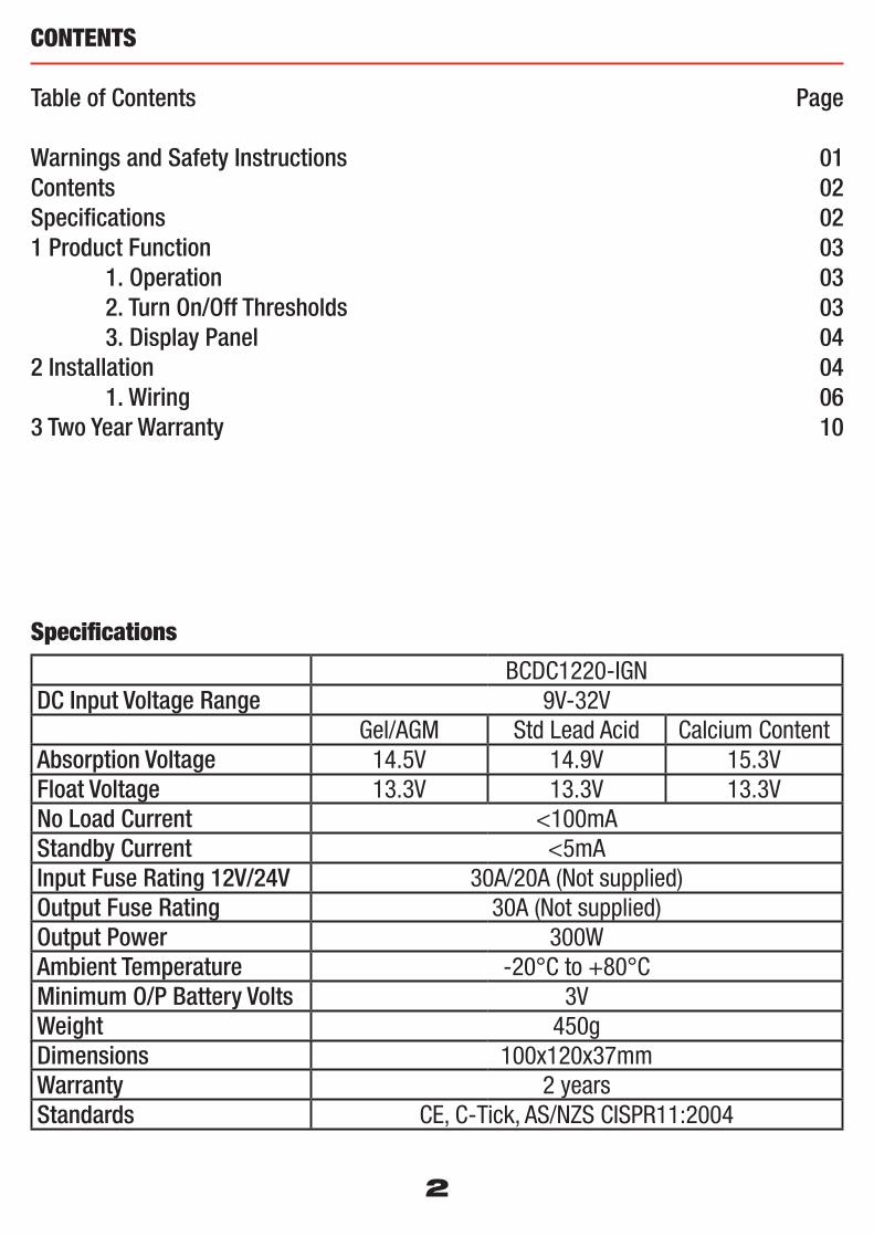
Warnings and Safety Instructions 01Contents 02Specifi cations 021 Product Function 03 1. Operation 03 2. Turn On/Off Thresholds 03 3. Display Panel 042 Installation 04 1. Wiring 063 Two Year Warranty 10
Specifi cations
BCDC1220-IGNDC Input Voltage Range 9V-32V
Gel/AGM Std Lead Acid Calcium ContentAbsorption Voltage 14.5V 14.9V 15.3VFloat Voltage 13.3V 13.3V 13.3VNo Load Current <100mAStandby Current <5mAInput Fuse Rating 12V/24V 30A/20A (Not supplied)Output Fuse Rating 30A (Not supplied)Output Power 300WAmbient Temperature -20°C to +80°CMinimum O/P Battery Volts 3VWeight 450gDimensions 100x120x37mmWarranty 2 yearsStandards CE, C-Tick, AS/NZS CISPR11:2004
2
1 PRODUCT FUNCTION
The BCDC1220-IGN is a multi stage, 12V, 20A, DC-DC battery charger that operates from an input of either 12V or 24V nominal. The input voltage of the BCDC1220-IGN can be above, below or equal to the output voltage making it ideal for charging from a 24V vehicle or charging an auxiliary 12V battery where the distance from the main battery may cause a signifi cant voltage drop. The BCDC1220-IGN is also designed to isolate the main battery from the auxiliary battery, to avoid over-discharging the main battery and operate with variable voltage alternators
1.1 Operation
When the BCDC1220-IGN is turned on, it will move into the bulk charging stage called Boost stage. Boost stage maintains a constant current until the battery voltage reaches its set point. The current in Boost stage may vary during operation in order to maintain safe operating temperature.The charger will then move to Absorption stage. This stage maintains a constant voltage level until the battery is full, after which the charger will enter fl oat stage.Float stage maintains 13.3V on the output battery, keeping the battery topped up. This counteracts the battery’s self discharging. When a load applied to the battery causes it to lose charge, the charger will move back into Boost.
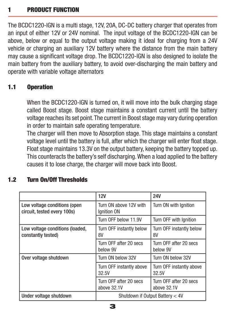
1.2 Turn On/Off Thresholds
12V 24V
Low voltage conditions (open circuit, tested every 100s)
Turn ON above 12V with Ignition ON
Turn ON with Ignition
Turn OFF below 11.9V Turn OFF with Ignition
Low voltage conditions (loaded, constantly tested)
Turn OFF instantly below 8V
Turn OFF instantly below 8V
Turn OFF after 20 secs below 9V
Turn OFF after 20 secs below 9V
Over voltage shutdown Turn ON below 32V Turn ON below 32V
Turn OFF instantly above 32.5V
Turn OFF instantly above 32.5V
Turn OFF after 20 secs above 32.1V
Turn OFF after 20 secs above 32.1V
Under voltage shutdown Shutdown if Output Battery < 4V
3
1 PRODUCT FUNCTION
1.3 Display Panel
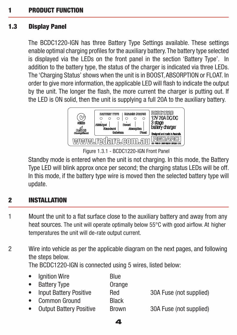
The BCDC1220-IGN has three Battery Type Settings available. These settings enable optimal charging profi les for the auxiliary battery. The battery type selected is displayed via the LEDs on the front panel in the section ‘Battery Type’. In addition to the battery type, the status of the charger is indicated via three LEDs. The ‘Charging Status’ shows when the unit is in BOOST, ABSORPTION or FLOAT. In order to give more information, the applicable LED will fl ash to indicate the output by the unit. The longer the fl ash, the more current the charger is putting out. If the LED is ON solid, then the unit is supplying a full 20A to the auxiliary battery.
Standby mode is entered when the unit is not charging. In this mode, the Battery Type LED will blink approx once per second; the charging status LEDs will be off. In this mode, if the battery type wire is moved then the selected battery type will update.
2 INSTALLATION
1 Mount the unit to a fl at surface close to the auxiliary battery and away from any heat sources. The unit will operate optimally below 55°C with good airfl ow. At higher temperatures the unit will de-rate output current.
2 Wire into vehicle as per the applicable diagram on the next pages, and following the steps below. The BCDC1220-IGN is connected using 5 wires, listed below:
• Ignition Wire Blue • Battery Type Orange • Input Battery Positive Red 30A Fuse (not supplied)• Common Ground Black • Output Battery Positive Brown 30A Fuse (not supplied)
4
RoHSCompliant
BCDC122012V 20A DC/DC3 stagebattery chargerDesigned and made in Australia
BATTERY TYPE CHARGE STATUS
AGM/gelStandard
Calcium
BoostAbsorption
Float
Figure 1.3.1 - BCDC1220-IGN Front Panel
5
2 INSTALLATION
1. Wire the ‘Common Ground’ wire to a ground point that is common to both the Start battery and the Auxiliary battery to be charged. This point MUST be on the chassis of the vehicle or on the chassis of the trailer/camper/caravan, NOT directly wired to the main battery.
2. Wire the ‘Output Battery Positive’ to the Auxiliary battery positive terminal. Ideally the BCDC unit should be a maximum of 1 metre in cable length from the battery positive terminal, and should be wired with a minimum of 3mm² or 5mm auto cable.
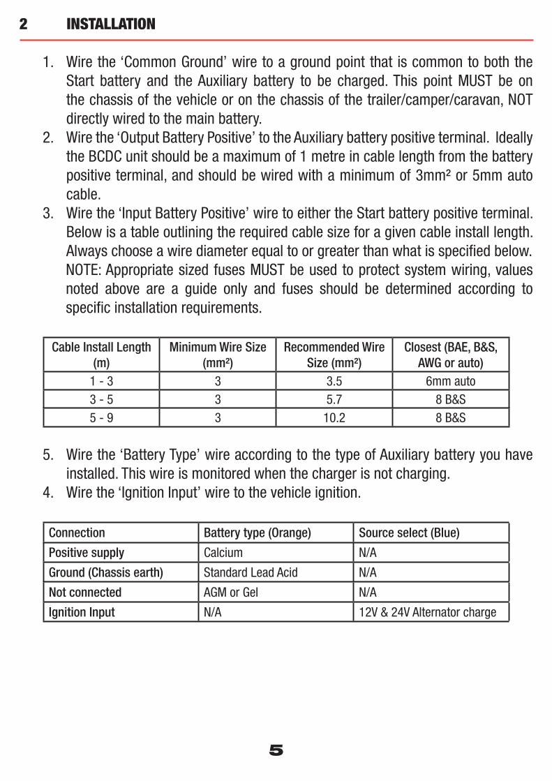
3. Wire the ‘Input Battery Positive’ wire to either the Start battery positive terminal. Below is a table outlining the required cable size for a given cable install length. Always choose a wire diameter equal to or greater than what is specifi ed below.NOTE: Appropriate sized fuses MUST be used to protect system wiring, values noted above are a guide only and fuses should be determined according to specifi c installation requirements.
Cable Install Length (m)
Minimum Wire Size (mm²)
Recommended Wire Size (mm²)
Closest (BAE, B&S, AWG or auto)
1 - 3 3 3.5 6mm auto3 - 5 3 5.7 8 B&S5 - 9 3 10.2 8 B&S
5. Wire the ‘Battery Type’ wire according to the type of Auxiliary battery you have installed. This wire is monitored when the charger is not charging.
4. Wire the ‘Ignition Input’ wire to the vehicle ignition.
Connection Battery type (Orange) Source select (Blue)
Positive supply Calcium N/A
Ground (Chassis earth) Standard Lead Acid N/A
Not connected AGM or Gel N/A
Ignition Input N/A 12V & 24V Alternator charge

6
2 INSTALLATION
IMPORTANT NOTE: Battery type selection refers to a typical installation where the battery and unit are mounted in a low to mid temperature situation. For situations of higher temperature such as under the bonnet or in a caravan battery box, a softer profi le (eg Std Lead Acid instead of Calcium) may need to be selected to avoid damage to the battery.
2.1 Wiring
The wires on the BCDC1220 unit carry higher than 20 Amp, and it is important to make a good, low resistance, electrical connection that will not degrade over time. Failure to make a good, reliable contact may result in breakdown of the wire insulation and cause a short circuit, or worst case a fi re. We recommend that this activity be undertaken by an appropriately trained person.Redarc recommends using a soldered butt splice crimp connection that is covered with heatshrink. The process should be to feed the heatshrink over the wires, crimp the wires into the butt splice, then solder the wires on the butt splice, and fi nally heat the heatshrink. Do not solder the wire before crimping. The appropriate sized butt splice should be selected: for example if 8AWG wires are used to connect the unit then an 8AWG butt splice should be used. If the wire gauge brought up to the unit is larger than the 8AWG, then it is recommended to use a butt splice that has two different size entrys, each matching the respective wire size. Various butt splices are available from auto electrical suppliers.Crimping provides good mechanical connection, soldering provides a long lasting electrical connection and forming of the heatshrink will prevent any shorting/contact with your vehicle chassis.
The term ‘crimping’ refers to a method of fi rmly attaching a terminal or contact to the end of an electrical conductor by pressure forming or reshaping a metal barrel onto the connector. The forming of a satisfactory crimp is dependent upon the correct combination of conductor, crimp barrel and crimping tool. When the correct combination of equipment is employed, a crimp that has both good electrical and mechanical characteristics will be formed.Butt splices are used to dress and terminate multiple conductors of the same or different gauges in an end-to-end or series confi guration.
12V
LoadsLoadFuse
30AFuse
All ground points mustbe connected to chassis
earth.
AuxiliaryBattery
Batteryconfig
wire
StartBattery
30AFuse
Note: Power wires must be at least 3mm² and must becrimped using anappropriate crimp tool.
INPUT
To vehicle ignition
7
2 INSTALLATION
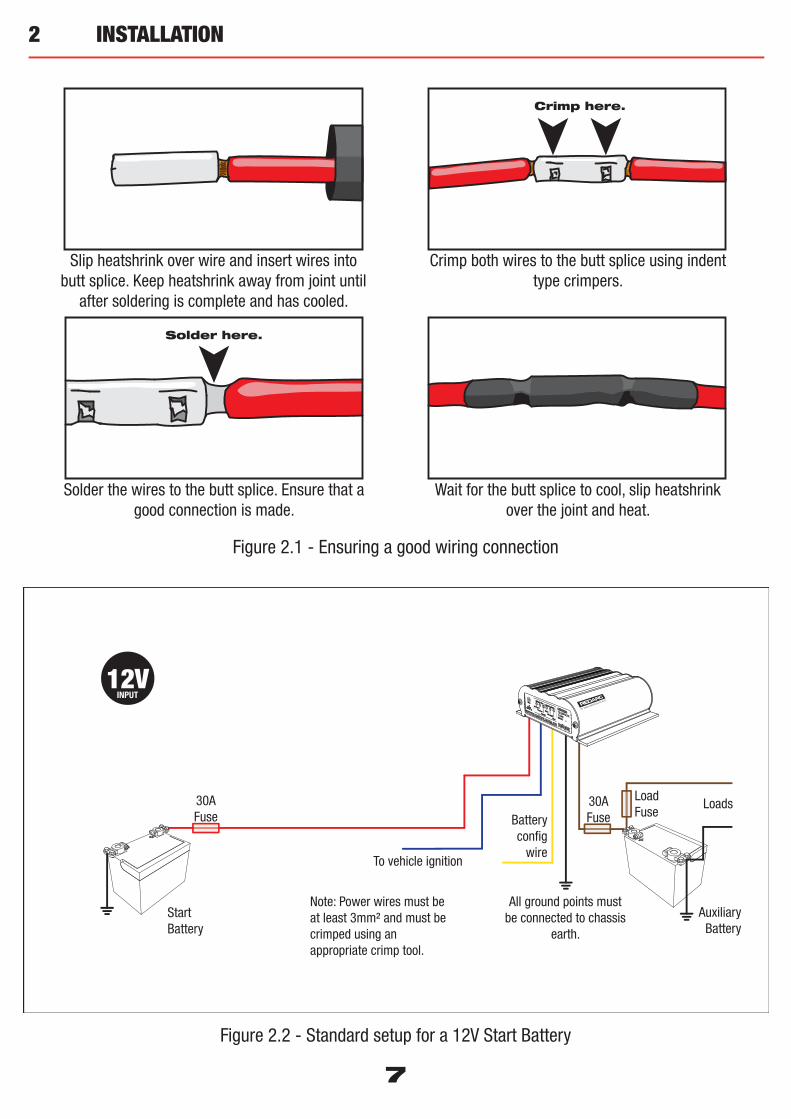
Figure 2.2 - Standard setup for a 12V Start Battery
Crimp here.
Solder here.
Figure 2.1 - Ensuring a good wiring connection
Slip heatshrink over wire and insert wires into butt splice. Keep heatshrink away from joint until
after soldering is complete and has cooled.
Crimp both wires to the butt splice using indent type crimpers.
Solder the wires to the butt splice. Ensure that a good connection is made.
Wait for the butt splice to cool, slip heatshrink over the joint and heat.
2 INSTALLATION
Loads30AFuseBattery
configwire
StartBattery
20AFuse
LoadFuse
All ground points mustbe connected to chassis
earth.
AuxiliaryBattery
Note: Power wires must be at least 3mm² and must becrimped using anappropriate crimp tool.
To vehicle ignition
24VINPUT
12VINPUT
24VINPUT
OR
Loads30AFuseBattery
configwire
StartBattery
20AFuse
LoadFuse
All ground points mustbe connected to chassis
earth.
AuxiliaryBattery
INPUT
Note: Power wires must be at least 3mm² and must becrimped using anappropriate crimp tool.
To vehicle ignition
30A N/O Relay
8
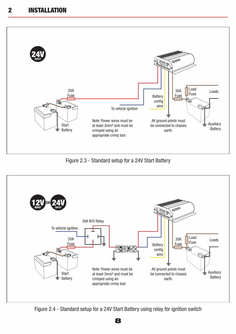
Figure 2.4 - Standard setup for a 24V Start Battery using relay for ignition switch
Figure 2.3 - Standard setup for a 24V Start Battery

9
10
3 TWO YEAR PRODUCT WARRANTY
Over the last three decades our company has established a reputation as the power conversion specialist. Over the last three decades our company has established a reputation as the power conversion specialist. A 100% Australian-owned company, we have met the needs of customers in transport and other industries through exciting, innovative thinking.A 100% Australian-owned company, we have met the needs of customers in transport and other industries through exciting, innovative thinking.We believe in total customer satisfaction and practice this by offering our customers:We believe in total customer satisfaction and practice this by offering our customers:• Technical advice free of jargon and free of charge• Technical advice free of jargon and free of charge• Prompt turnaround of orders throughout Australia and globally• Prompt turnaround of orders throughout Australia and globally• Friendly, personalised, professional service and product support• Friendly, personalised, professional service and product supportIn the unlikely event that a technical issue arises with a Redarc product, customers are encouraged to initially contact the Redarc Technical Support Team on (08) 8322 4848 In the unlikely event that a technical issue arises with a Redarc product, customers are encouraged to initially contact the Redarc Technical Support Team on (08) 8322 4848 or or [email protected]@redarc.com.au for prompt and effi cient diagnosis and product support. for prompt and effi cient diagnosis and product support.Our goods come with guarantees that cannot be excluded under the Australian Consumer Law. You are entitled to a replacement or refund for a major failure and compensation for Our goods come with guarantees that cannot be excluded under the Australian Consumer Law. You are entitled to a replacement or refund for a major failure and compensation for any other reasonably foreseeable loss or damage. You are also entitled to have the goods repaired or replaced if the goods fail to be of acceptable quality and the failure does not any other reasonably foreseeable loss or damage. You are also entitled to have the goods repaired or replaced if the goods fail to be of acceptable quality and the failure does not amount to a major failure.amount to a major failure.
The benefi ts of this Warranty are in addition to other rights and remedies available at law in respect of the Products and shall not derogate from any applicable mandatory statutory The benefi ts of this Warranty are in addition to other rights and remedies available at law in respect of the Products and shall not derogate from any applicable mandatory statutory provisions or rights under the Australian Consumer Law. provisions or rights under the Australian Consumer Law.
Redarc Electronics Pty Ltd atf the Redarc Trust trading as Redarc Electronics (“Redarc Electronics Pty Ltd atf the Redarc Trust trading as Redarc Electronics (“RedarcRedarc”) offers a warranty in respect of its Products where the Products are purchased from an ”) offers a warranty in respect of its Products where the Products are purchased from an authorised distributor or reseller of Redarc by a person (“authorised distributor or reseller of Redarc by a person (“PurchaserPurchaser”), on the terms and conditions, and for the duration, outlined below in this document (“”), on the terms and conditions, and for the duration, outlined below in this document (“WarrantyWarranty”).”).
1. In this Warranty, the term Products means:1.1 all products manufactured or supplied by Redarc (excluding its solar products
which are covered by Redarc’s Solar Product Warranty); and1.2 any component of or accessory for any product in clause 1.1 manufactured or
supplied by Redarc.
Offer and duration of product warranties2. Redarc warrants that its Products will be free, under normal application, installation,
use and service conditions, from defects in materials and workmanship affecting normal use, for 2 years from the date of purchase (Warranty Period).
3. Where a Product malfunctions or becomes inoperative during the Warranty Period, due to a defect in materials or workmanship, as determined by Redarc, then subject to further rights conferred by the Australian Consumer Law on the Purchaser, Redarc will, in exercise of its sole discretion, either:3.1 repair the defective Product;3.2 replace the defective Product; or 3.3 provide a refund to the Purchaser for the purchase price paid for the defective
Product,without charge to the Purchaser.
4. The warranty given by Redarc in clause 3 covers the reasonable costs of delivery and installation of any repaired or replaced Products or components of Products to the Purchaser’s usual residential address notifi ed to Redarc, together with the reasonable costs of removal and return of any Products determined by Redarc to be defective.
5. If the Purchaser incurs expenses of the nature referred to in clause 4 in the context of making a claim pursuant to this Warranty that is accepted by Redarc, the Purchaser will be entitled to claim for reimbursement of those expenses which Redarc determines, in exercise of its sole discretion, to be reasonably incurred, provided that the claim is notifi ed to Redarc in writing at the postal address or email address specifi ed in clause 21 and includes:5.1 details of the relevant expenses incurred by the Purchaser; and 5.2 proof of the relevant expenses having been incurred by the Purchaser.
Exclusions and limitations6. This Warranty will not apply to, or include any defect, damage, fault, failure
or malfunction of a Product, which Redarc determines, in exercise of its sole discretion, to be due to:6.1 normal wear and tear or exposure to weather conditions over time;6.2 accident, misuse, abuse, negligence, vandalism, alteration or modifi cation;6.3 non-observance of any of the instructions supplied by Redarc, including
instructions concerning installation, confi guring, connecting, commissioning, use or application of the Product, including without limitation choice of location;
6.4 failure to ensure proper maintenance of the Product strictly in accordance with Redarc’s instructions or failure to ensure proper maintenance of any associated equipment or machinery;
6.5 repairs to the Product that are not strictly in accordance with Redarc’s instructions;
6.6 installation, repairs or maintenance of the Product by, or under the supervision of, a person who is not a qualifi ed auto electrician or technician, or if non-genuine or non-approved parts have been fi tted;
6.7 faulty power supply, power failure, electrical spikes or surges, lightning, fl ood, storm, hail, extreme heat, fi re or other occurrence outside the control of Redarc;
6.8 use other than for any reasonable purpose for which the Product was manufactured;
6.9 any indirect or incidental damage of whatever nature outside the control of Redarc.
7. Warranty claims in respect of a Product must be made in writing to Redarc at the postal address or email address specifi ed in clause 21 within the Warranty Period. Such claims must include the following:7.1 details of the alleged defect or fault and the circumstances surrounding the
defect or fault;7.2 evidence of the claim, including photographs of the Product (where the subject
of the claim is capable of being photographed);7.3 the serial number of the Product, specifi ed on the label affi xed to the Product;
and7.4 proof of purchase documentation for the Product from an authorised distributor
or reseller of Redarc, which clearly shows the date and place of purchase.The return of any Products without the prior written instructions of Redarc will not be accepted by Redarc.
8. Without limiting any other clause in this Warranty, Redarc has the right to reject any Warranty claim made by a Purchaser pursuant to this Warranty where:8.1 the Purchaser does not notify Redarc in writing of a Warranty claim within the
Warranty Period;8.2 the Purchaser does not notify Redarc in writing of a Warranty claim within 1
month of becoming aware of the relevant circumstances giving rise to the claim, so that any further problems with the Product are minimised;
8.3 the serial number of the Product has been altered, removed or made illegible without the written authority of Redarc;
8.4 the Purchaser is unable to provide proof of purchase documentation in accordance with clause 7.4 or evidence that the Product was properly installed and removed (if relevant), and that proper maintenance has been performed on the Product, by, or under the supervision of, a qualifi ed auto electrician or technician, in accordance with the instructions of Redarc.
9. If the Product is found to be working satisfactorily on return to Redarc or upon investigation by Redarc, the Purchaser must pay Redarc’s reasonable costs of testing and investigating the Product in addition to shipping and transportation charges. Where Redarc is in possession of the Product, the Product will be returned to the Purchaser on receipt of the amount charged.
10. Any replaced Products or components of Products shall become the property of Redarc.
11. Redarc may, in exercise of its sole discretion, deliver another type of Product or component of a Product (different in size, colour, shape, weight, brand and/or other specifi cations) in fulfi lling its obligations under this Warranty, in the event that Redarc has discontinued manufacturing or supplying the relevant Product or component at the time of the Warranty claim, or where such Product or component is superior to that originally purchased by the Purchaser.
Other conditions of Warranty12. If the Purchaser acquired a Product for the purpose of resupply, then this Warranty
shall not apply to that Product.13. In particular, the sale of a Product via an online auction, online store or other
internet website by a party that is not an authorised distributor or reseller of the Product will be deemed to be a resupply within the meaning of the Australian Consumer Law and will render this Warranty void, as Redarc has no control over the storage, handling, quality or safety of Products sold by such persons.
14. A Purchaser shall only be entitled to the benefi t of this Warranty after all amounts owing in respect of the Product have been paid.
15. While Redarc warrants that the Products will be free from defects in materials and workmanship in the circumstances set out in this Warranty, to the maximum extent permitted by law Redarc does not warrant that the operation of the Products will be uninterrupted or error-free.
16. To the maximum extent permitted by law, Redarc’s determination of the existence of any defect and the cause of any defect will be conclusive.
17. Spare parts or materials for the Products are guaranteed to be available for a period of at least 2 years after purchase of the Products.
18. The agents, offi cers and employees of any distributor or reseller of the Products and of Redarc are not authorised to vary or extend the terms of this Warranty.
19. Redarc shall not be responsible or liable to the Customer or any third party in connection with any non-performance or delay in performance of any terms and conditions of this Warranty, due to acts of God, war, riots, strikes, warlike conditions, plague or other epidemic, fi re, fl ood, blizzard, hurricane, changes of public policies, terrorism and other events which are beyond the control of Redarc. In such circumstances, Redarc may suspend performance of this Warranty without liability for the period of the delay reasonably attributable to such causes.
20. If a clause or part of a clause in this Warranty can be read in a way that makes it illegal, unenforceable or invalid, but can also be read in a way that makes it legal, enforceable and valid, it must be read in the latter way. If any clause or part of a clause in this Warranty is illegal, unenforceable or invalid, that clause or part is to be treated as removed from this Warranty, but the rest of this Warranty is not affected.
Redarc’s contact details21. Redarc’s contact details for the sending of Warranty claims under this Warranty are:
Redarc Electronics Pty Ltd23 Brodie Road (North), Lonsdale SA 5160Email: [email protected] Telephone: +61 8 8322 4848

www.redarc.com.auWARBCDC1220-IGN - REV3
Free technical assistance! please contact
Redarc Electronics23 Brodie Road North, Lonsdale SA
(08) 8322 [email protected]
www.redarc.com.au
Copyright © 2013 Redarc Electronics Pty Ltd. All rights reserved.Whilst all care was taken to ensure the contents of this manual were accurate at the time of
printing, we take no responsibility for any errors or omissions.