2070 profinet module - eilersen profinet module status and weight transfer using profinet . 2 070...
TRANSCRIPT

Kokkedal Industripark 4
DK-2980 Kokkedal
Denmark
Tel +45 49 180 100
Fax +45 49 180 200
Applies for:
Software: CONCTR_4.160530.1v0
Document no.: 0530mu2070-1v0
Date: 2016-06-15
Rev.: 1v0
2070 PROFINET MODULE Status and weight transfer using PROFINET
2070 CONCTR_4.160530.1v0: User manual
WWW.EILERSEN.COM
Version: 2016-06-15, rev.: 1v0 Page: 2
1) Contents
1) Contents .................................................................................................................. 2 2) Introduction .............................................................................................................. 3
2.1 Introduction ......................................................................................................... 3 2.2 ATEX (Ex) specification .......................................................................................... 3
3) Data Exchange .......................................................................................................... 4 3.1 PROFINET communication ...................................................................................... 4 3.2 Data formats ........................................................................................................ 5
3.2.1 Unsigned integer format (16 bit) ....................................................................... 5 3.2.2 Signed integer format (32 bit) ........................................................................... 5
3.3 Scaling................................................................................................................. 6 3.4 Measurement time ................................................................................................ 6 3.5 Filtering ............................................................................................................... 7
4) Data Processing ........................................................................................................ 8 4.1 Zeroing, calibration and weight calculation ............................................................... 8
4.1.1 Zeroing of weighing system .............................................................................. 8 4.1.2 Corner calibration of weighing system ................................................................ 9 4.1.3 Calculation of uncalibrated system weight ........................................................... 9 4.1.4 System calibration of weighing system ............................................................. 10
5) Installation of System .............................................................................................. 11 5.1 Checklist during installation .................................................................................. 11
6) Hardware Description ............................................................................................... 12 6.1 2070 overview .................................................................................................... 12 6.2 Connection of power (J2) ..................................................................................... 13 6.3 Connection of loadcells (J7) .................................................................................. 13 6.4 PROFINET connectors .......................................................................................... 13 6.5 RS485 connector (J1) .......................................................................................... 14
6.5.1 DIP-switch settings ........................................................................................ 14 6.5.2 Light Emitting Diodes (LEDs) ........................................................................... 15
6.6 Update times ...................................................................................................... 16 7) Appendices ............................................................................................................. 17
7.1 Appendix A – PROFINET Configuration tips ............................................................. 17 7.1.1 MAC addresses .............................................................................................. 17 7.1.2 GSDML file .................................................................................................... 17 7.1.3 Factory settings ............................................................................................. 17 7.1.4 Setting DeviceName, IP Address etc. ............................................................... 17 7.1.5 Data sizes ..................................................................................................... 17
7.2 Appendix B – Internal Features ............................................................................. 18 7.2.1 Connectors ................................................................................................... 18 7.2.2 Jumper settings ............................................................................................. 19 7.2.3 Light Emitting Diodes (LEDs) ........................................................................... 19
7.3 Appendix C – Status Codes ................................................................................... 20
2070 CONCTR_4.160530.1v0: User manual
WWW.EILERSEN.COM
Version: 2016-06-15, rev.: 1v0 Page: 3
2) Introduction
2.1 Introduction
This document describes the use of a 2070 PROFINET module from Eilersen Electric, when it is equipped with the program listed on the front page.
With the program specified on the front page, the 2070 PROFINET module is
capable of transmitting weight and status for up to 4 loadcells in a single tele-gram. Each loadcell is connected to the PROFINET module through a loadcell
interface module.
It is possible to connect the 2070 PROFINET module to a PROFINET network, where it will act as a slave. It will then be possible from the PROFINET master
to read status and weight for each of the connected loadcells. Functions as ze-roing, calibration and calculation of system weight(s) must be implemented
outside the 2070 in the PROFINET master.
By use of DIP-switches it is possible to select measurement time and include one of 15 different FIR filters, which will be used to filter the loadcell signals,
as well as selecting the desired scaling of the loadcell signals.
Exchange of data between master and slave takes place as described in the
following.
2.2 ATEX (Ex) specification
IMPORTANT: Load cell modules and instrumentation must be placed
outside the hazardous zone if the load cells are used in hazardous ATEX (Ex) area. Furthermore, only ATEX certified load cells and in-strumentation can be used in ATEX applications.
2070 CONCTR_4.160530.1v0: User manual
WWW.EILERSEN.COM
Version: 2016-06-15, rev.: 1v0 Page: 4
3) Data Exchange
3.1 PROFINET communication
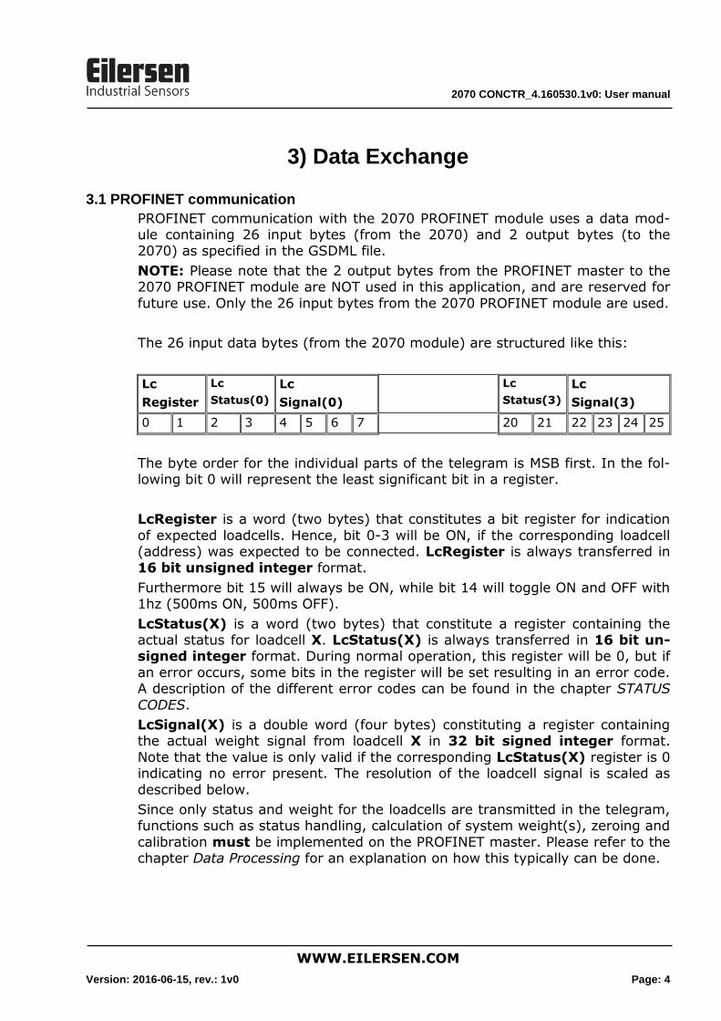
PROFINET communication with the 2070 PROFINET module uses a data mod-ule containing 26 input bytes (from the 2070) and 2 output bytes (to the 2070) as specified in the GSDML file.
NOTE: Please note that the 2 output bytes from the PROFINET master to the 2070 PROFINET module are NOT used in this application, and are reserved for
future use. Only the 26 input bytes from the 2070 PROFINET module are used.
The 26 input data bytes (from the 2070 module) are structured like this:
Lc
Register
Lc
Status(0)
Lc
Signal(0)
Lc
Status(3)
Lc
Signal(3)
0 1 2 3 4 5 6 7 20 21 22 23 24 25
The byte order for the individual parts of the telegram is MSB first. In the fol-lowing bit 0 will represent the least significant bit in a register.
LcRegister is a word (two bytes) that constitutes a bit register for indication
of expected loadcells. Hence, bit 0-3 will be ON, if the corresponding loadcell (address) was expected to be connected. LcRegister is always transferred in 16 bit unsigned integer format.
Furthermore bit 15 will always be ON, while bit 14 will toggle ON and OFF with 1hz (500ms ON, 500ms OFF).
LcStatus(X) is a word (two bytes) that constitute a register containing the actual status for loadcell X. LcStatus(X) is always transferred in 16 bit un-signed integer format. During normal operation, this register will be 0, but if
an error occurs, some bits in the register will be set resulting in an error code. A description of the different error codes can be found in the chapter STATUS
CODES.
LcSignal(X) is a double word (four bytes) constituting a register containing the actual weight signal from loadcell X in 32 bit signed integer format.
Note that the value is only valid if the corresponding LcStatus(X) register is 0 indicating no error present. The resolution of the loadcell signal is scaled as
described below.
Since only status and weight for the loadcells are transmitted in the telegram, functions such as status handling, calculation of system weight(s), zeroing and
calibration must be implemented on the PROFINET master. Please refer to the chapter Data Processing for an explanation on how this typically can be done.
2070 CONCTR_4.160530.1v0: User manual
WWW.EILERSEN.COM
Version: 2016-06-15, rev.: 1v0 Page: 5
3.2 Data formats
The PROFINET communication can transfer data in the following three data
formats. Please refer to other literature for further information on these for-mats as it is outside the scope of this document.
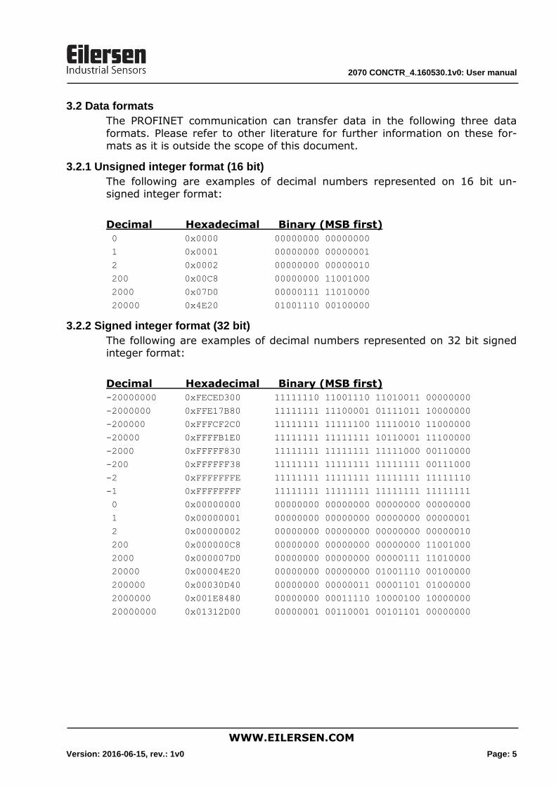
3.2.1 Unsigned integer format (16 bit)
The following are examples of decimal numbers represented on 16 bit un-signed integer format:
Decimal Hexadecimal Binary (MSB first)
0 0x0000 00000000 00000000
1 0x0001 00000000 00000001
2 0x0002 00000000 00000010
200 0x00C8 00000000 11001000
2000 0x07D0 00000111 11010000
20000 0x4E20 01001110 00100000
3.2.2 Signed integer format (32 bit)
The following are examples of decimal numbers represented on 32 bit signed integer format:
Decimal Hexadecimal Binary (MSB first)
-20000000 0xFECED300 11111110 11001110 11010011 00000000
-2000000 0xFFE17B80 11111111 11100001 01111011 10000000
-200000 0xFFFCF2C0 11111111 11111100 11110010 11000000
-20000 0xFFFFB1E0 11111111 11111111 10110001 11100000
-2000 0xFFFFF830 11111111 11111111 11111000 00110000
-200 0xFFFFFF38 11111111 11111111 11111111 00111000
-2 0xFFFFFFFE 11111111 11111111 11111111 11111110
-1 0xFFFFFFFF 11111111 11111111 11111111 11111111
0 0x00000000 00000000 00000000 00000000 00000000
1 0x00000001 00000000 00000000 00000000 00000001
2 0x00000002 00000000 00000000 00000000 00000010
200 0x000000C8 00000000 00000000 00000000 11001000
2000 0x000007D0 00000000 00000000 00000111 11010000
20000 0x00004E20 00000000 00000000 01001110 00100000
200000 0x00030D40 00000000 00000011 00001101 01000000
2000000 0x001E8480 00000000 00011110 10000100 10000000
20000000 0x01312D00 00000001 00110001 00101101 00000000
2070 CONCTR_4.160530.1v0: User manual
WWW.EILERSEN.COM
Version: 2016-06-15, rev.: 1v0 Page: 6
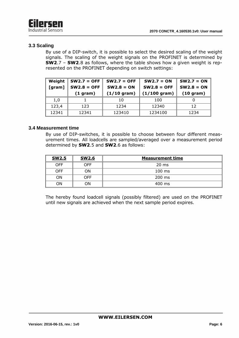
3.3 Scaling
By use of a DIP-switch, it is possible to select the desired scaling of the weight
signals. The scaling of the weight signals on the PROFINET is determined by SW2.7 – SW2.8 as follows, where the table shows how a given weight is rep-resented on the PROFINET depending on switch settings:
Weight
[gram]
SW2.7 = OFF
SW2.8 = OFF
(1 gram)
SW2.7 = OFF
SW2.8 = ON
(1/10 gram)
SW2.7 = ON
SW2.8 = OFF
(1/100 gram)
SW2.7 = ON
SW2.8 = ON
(10 gram)
1,0 1 10 100 0
123,4 123 1234 12340 12
12341 12341 123410 1234100 1234
3.4 Measurement time
By use of DIP-switches, it is possible to choose between four different meas-
urement times. All loadcells are sampled/averaged over a measurement period determined by SW2.5 and SW2.6 as follows:
SW2.5 SW2.6 Measurement time
OFF OFF 20 ms
OFF ON 100 ms
ON OFF 200 ms
ON ON 400 ms
The hereby found loadcell signals (possibly filtered) are used on the PROFINET until new signals are achieved when the next sample period expires.

2070 CONCTR_4.160530.1v0: User manual
WWW.EILERSEN.COM
Version: 2016-06-15, rev.: 1v0 Page: 7
3.5 Filtering
By use of DIP-switches, it is possible to include one of 15 different FIR filters,
which will be used to filter the loadcell signals. Thus it is possible, to send the unfiltered loadcell signals achieved over the selected measurement period through one of the following FIR filters, before the results are transmitted on
the PROFINET:
SW2.4 SW2.3 SW2.2 SW2.1 No. Taps Frequency Damping
Tavg = 20ms
Tavg = 200ms
OFF OFF OFF OFF 0 - - - -
ON OFF OFF OFF 1 7 12.0 Hz 1.2 Hz -60dB
OFF ON OFF OFF 2 9 10.0 Hz 1.0 Hz -60dB
ON ON OFF OFF 3 9 12.0 Hz 1.2 Hz -80dB
OFF OFF ON OFF 4 12 8.0 Hz 0.8 Hz -60dB
ON OFF ON OFF 5 12 10.0 Hz 1.0 Hz -80dB
OFF ON ON OFF 6 15 8.0 Hz 0.8 Hz -80dB
ON ON ON OFF 7 17 6.0 Hz 0.6 Hz -60dB
OFF OFF OFF ON 8 21 6.0 Hz 0.6 Hz -80dB
ON OFF OFF ON 9 25 4.0 Hz 0.4 Hz -60dB
OFF ON OFF ON 10 32 4.0 Hz 0.4 Hz -80dB
ON ON OFF ON 11 50 2.0 Hz 0.2 Hz -60dB
OFF OFF ON ON 12 64 2.0 Hz 0.2 Hz -80dB
ON OFF ON ON 13 67 1.5 Hz 0.15 Hz -60dB
OFF ON ON ON 14 85 1.5 Hz 0.15 Hz -80dB
ON ON ON ON 15 100 1.0 Hz 0.10 Hz -60dB
NOTE: With all switches OFF no filtering is performed.
2070 CONCTR_4.160530.1v0: User manual
WWW.EILERSEN.COM
Version: 2016-06-15, rev.: 1v0 Page: 8
4) Data Processing
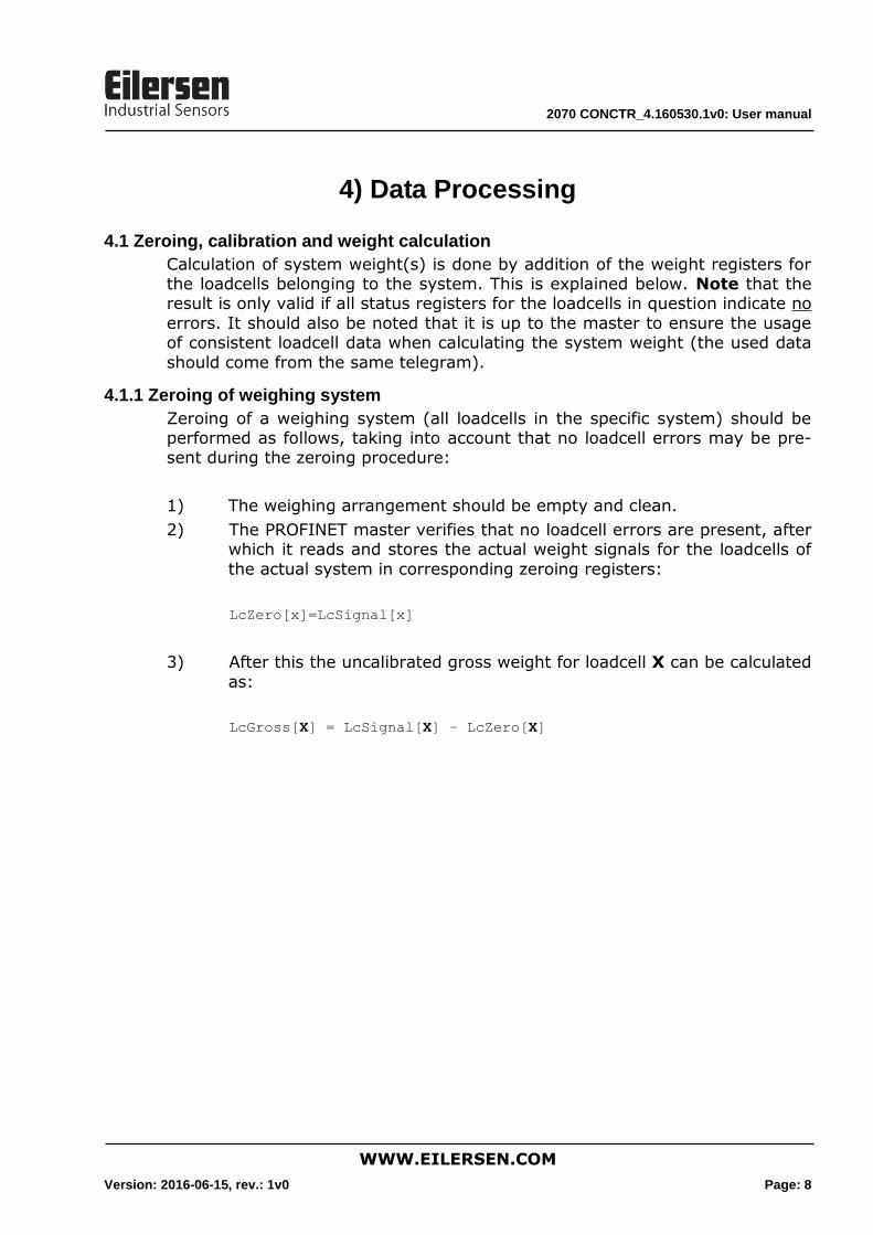
4.1 Zeroing, calibration and weight calculation
Calculation of system weight(s) is done by addition of the weight registers for the loadcells belonging to the system. This is explained below. Note that the result is only valid if all status registers for the loadcells in question indicate no
errors. It should also be noted that it is up to the master to ensure the usage of consistent loadcell data when calculating the system weight (the used data
should come from the same telegram).
4.1.1 Zeroing of weighing system
Zeroing of a weighing system (all loadcells in the specific system) should be performed as follows, taking into account that no loadcell errors may be pre-sent during the zeroing procedure:
1) The weighing arrangement should be empty and clean.
2) The PROFINET master verifies that no loadcell errors are present, after which it reads and stores the actual weight signals for the loadcells of
the actual system in corresponding zeroing registers:
LcZero[x]=LcSignal[x]
3) After this the uncalibrated gross weight for loadcell X can be calculated
as:
LcGross[X] = LcSignal[X] – LcZero[X]
2070 CONCTR_4.160530.1v0: User manual
WWW.EILERSEN.COM
Version: 2016-06-15, rev.: 1v0 Page: 9
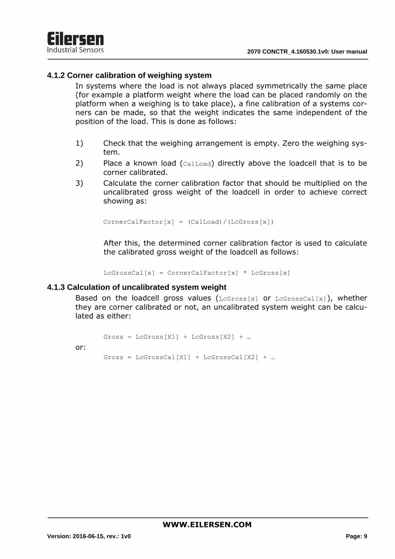
4.1.2 Corner calibration of weighing system
In systems where the load is not always placed symmetrically the same place
(for example a platform weight where the load can be placed randomly on the platform when a weighing is to take place), a fine calibration of a systems cor-ners can be made, so that the weight indicates the same independent of the
position of the load. This is done as follows:
1) Check that the weighing arrangement is empty. Zero the weighing sys-tem.
2) Place a known load (CalLoad) directly above the loadcell that is to be
corner calibrated.
3) Calculate the corner calibration factor that should be multiplied on the uncalibrated gross weight of the loadcell in order to achieve correct
showing as:
CornerCalFactor[x] = (CalLoad)/(LcGross[x])
After this, the determined corner calibration factor is used to calculate
the calibrated gross weight of the loadcell as follows:
LcGrossCal[x] = CornerCalFactor[x] * LcGross[x]
4.1.3 Calculation of uncalibrated system weight
Based on the loadcell gross values (LcGross[x] or LcGrossCal[x]), whether
they are corner calibrated or not, an uncalibrated system weight can be calcu-lated as either:
Gross = LcGross[X1] + LcGross[X2] + …
or:
Gross = LcGrossCal[X1] + LcGrossCal[X2] + …
2070 CONCTR_4.160530.1v0: User manual
WWW.EILERSEN.COM
Version: 2016-06-15, rev.: 1v0 Page: 10
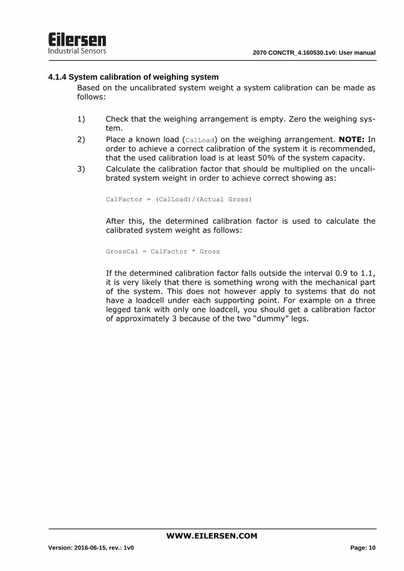
4.1.4 System calibration of weighing system
Based on the uncalibrated system weight a system calibration can be made as
follows:
1) Check that the weighing arrangement is empty. Zero the weighing sys-
tem.
2) Place a known load (CalLoad) on the weighing arrangement. NOTE: In
order to achieve a correct calibration of the system it is recommended,
that the used calibration load is at least 50% of the system capacity.
3) Calculate the calibration factor that should be multiplied on the uncali-
brated system weight in order to achieve correct showing as:
CalFactor = (CalLoad)/(Actual Gross)
After this, the determined calibration factor is used to calculate the
calibrated system weight as follows:
GrossCal = CalFactor * Gross
If the determined calibration factor falls outside the interval 0.9 to 1.1,
it is very likely that there is something wrong with the mechanical part of the system. This does not however apply to systems that do not have a loadcell under each supporting point. For example on a three
legged tank with only one loadcell, you should get a calibration factor of approximately 3 because of the two “dummy” legs.

2070 CONCTR_4.160530.1v0: User manual
WWW.EILERSEN.COM
Version: 2016-06-15, rev.: 1v0 Page: 11
5) Installation of System
5.1 Checklist during installation
During installation of the system, the following should be checked:
1. All hardware connections are made as described below.
2. If necessary, the PROFINET master should be configured to communi-cate with the 2070 PROFINET module using the supplied GSDML file.
3. Set the number of loadcells connected by use of SW1.2 – SW1.4 as de-scribed later.
4. Set the scaling/resolution of the weight signal by use of SW2.7 –
SW2.8 as described earlier.
5. Set the desired measurement time by use of SW2.5 – SW2.6 as de-
scribed earlier.
6. Select the desired filter by use of SW2.1 – SW2.4 as described earlier.
7. The loadcells are mounted mechanically and connected to the 2070
PROFINET module using their corresponding loadcell interface module (MCE2010). The loadcell addresses are set using the DIP-switches on
the loadcell interface modules, so that they forth running from address 0 (0-3).
8. The 2070 PROFINET module is connected to the PROFINET network us-
ing the PORT1 PROFINET connector (and possibly also PORT2) in the front of the 2070 module.
9. Power (24VDC) is applied at the 2 pole power connector in the front of the 2070 module as described in the hardware section, and the
PROFINET communication is started.
10.Verify that the BF, SF, MT, ST and D1 lamps of the 2070 module end up OFF.
11.Verify that the RDY lamp ends up green.
12.Verify that the TxBB lamp (green) on the 2070 PROFINET module is lit
(after 10 seconds) and that the TxBB lamps on all the loadcell interface modules are also lit (can flash slightly).
13.Verify that the 2070 PROFINET module has found the correct loadcells
(LcRegister), and that no loadcell errors are indicated (LcStatus(x)).
14.Verify that every loadcell gives a signal (LcSignal(x)) by placing a load
directly above each loadcell one after the other (possibly with a known load).
The system is now installed and a zero and fine calibration is made as de-scribed earlier. Finally verify that the weighing system(s) returns a value cor-
responding to a known actual load.
Note that in the above checklist no consideration has been made on which functions are implemented on the PROFINET master.
2070 CONCTR_4.160530.1v0: User manual
WWW.EILERSEN.COM
Version: 2016-06-15, rev.: 1v0 Page: 12
6) Hardware Description
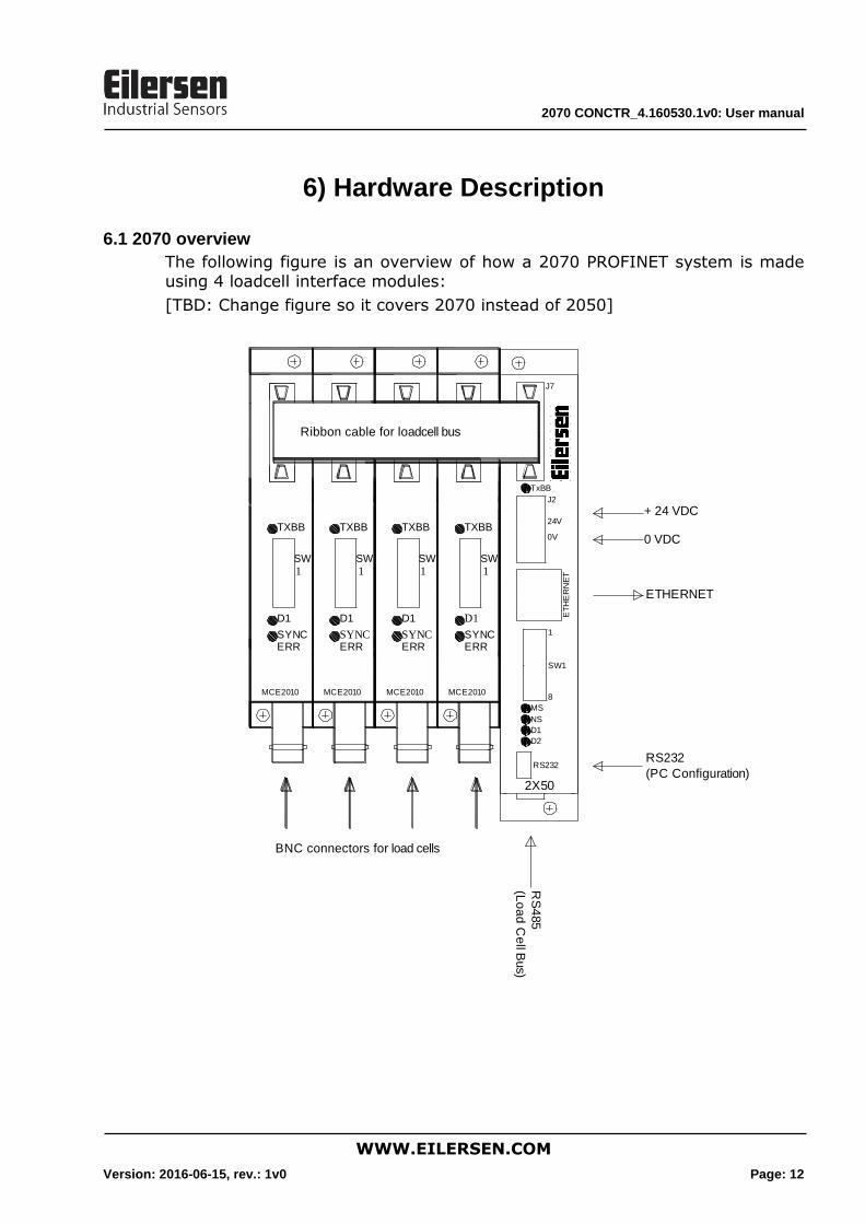
6.1 2070 overview
The following figure is an overview of how a 2070 PROFINET system is made using 4 loadcell interface modules:
[TBD: Change figure so it covers 2070 instead of 2050]
BNC connectors for load cells
Ribbon cable for loadcell bus
TXBB
D1
SYNCERR
SW1
MCE2010
SW1
MS
NS
D1
D2
RS232
24V
0V
TxBB
J7
1
8
2X50
ET
HE
RN
ET
J2
TXBB
D1
SYNCERR
SW1
MCE2010
+ 24 VDC
0 VDC
ETHERNET
TXBB
D1
SYNCERR
SW1
MCE2010
TXBB
D1
SYNCERR
SW1
MCE2010
RS232
RS
485
(Lo
ad
Ce
ll Bus)
(PC Configuration)
2070 CONCTR_4.160530.1v0: User manual
WWW.EILERSEN.COM
Version: 2016-06-15, rev.: 1v0 Page: 13
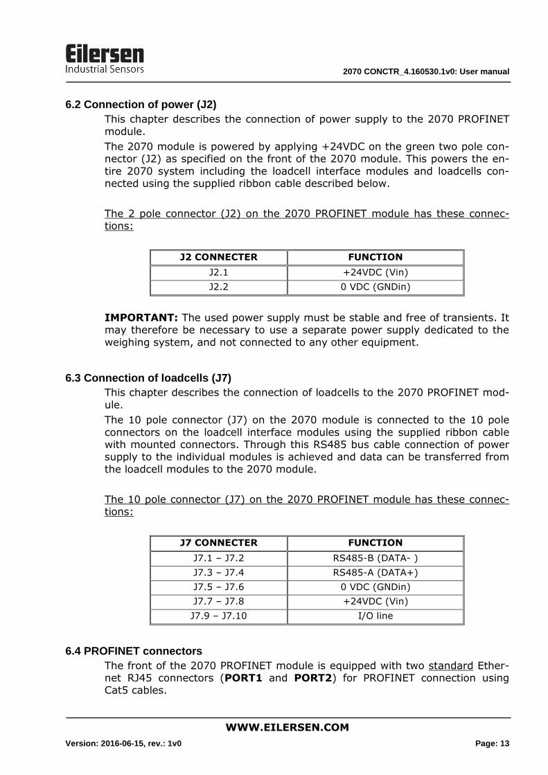
6.2 Connection of power (J2)
This chapter describes the connection of power supply to the 2070 PROFINET
module.
The 2070 module is powered by applying +24VDC on the green two pole con-nector (J2) as specified on the front of the 2070 module. This powers the en-
tire 2070 system including the loadcell interface modules and loadcells con-nected using the supplied ribbon cable described below.
The 2 pole connector (J2) on the 2070 PROFINET module has these connec-tions:
J2 CONNECTER FUNCTION
J2.1 +24VDC (Vin)
J2.2 0 VDC (GNDin)
IMPORTANT: The used power supply must be stable and free of transients. It may therefore be necessary to use a separate power supply dedicated to the
weighing system, and not connected to any other equipment.
6.3 Connection of loadcells (J7)
This chapter describes the connection of loadcells to the 2070 PROFINET mod-
ule.
The 10 pole connector (J7) on the 2070 module is connected to the 10 pole
connectors on the loadcell interface modules using the supplied ribbon cable with mounted connectors. Through this RS485 bus cable connection of power supply to the individual modules is achieved and data can be transferred from
the loadcell modules to the 2070 module.
The 10 pole connector (J7) on the 2070 PROFINET module has these connec-tions:
J7 CONNECTER FUNCTION
J7.1 – J7.2 RS485-B (DATA- )
J7.3 – J7.4 RS485-A (DATA+)
J7.5 – J7.6 0 VDC (GNDin)
J7.7 – J7.8 +24VDC (Vin)
J7.9 – J7.10 I/O line
6.4 PROFINET connectors
The front of the 2070 PROFINET module is equipped with two standard Ether-net RJ45 connectors (PORT1 and PORT2) for PROFINET connection using Cat5 cables.
2070 CONCTR_4.160530.1v0: User manual
WWW.EILERSEN.COM
Version: 2016-06-15, rev.: 1v0 Page: 14
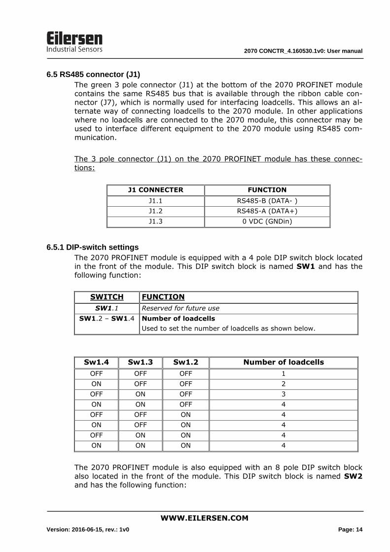
6.5 RS485 connector (J1)
The green 3 pole connector (J1) at the bottom of the 2070 PROFINET module
contains the same RS485 bus that is available through the ribbon cable con-nector (J7), which is normally used for interfacing loadcells. This allows an al-ternate way of connecting loadcells to the 2070 module. In other applications
where no loadcells are connected to the 2070 module, this connector may be used to interface different equipment to the 2070 module using RS485 com-
munication.
The 3 pole connector (J1) on the 2070 PROFINET module has these connec-
tions:
J1 CONNECTER FUNCTION
J1.1 RS485-B (DATA- )
J1.2 RS485-A (DATA+)
J1.3 0 VDC (GNDin)
6.5.1 DIP-switch settings
The 2070 PROFINET module is equipped with a 4 pole DIP switch block located in the front of the module. This DIP switch block is named SW1 and has the following function:
SWITCH FUNCTION
SW1.1 Reserved for future use
SW1.2 – SW1.4 Number of loadcells
Used to set the number of loadcells as shown below.
Sw1.4 Sw1.3 Sw1.2 Number of loadcells
OFF OFF OFF 1
ON OFF OFF 2
OFF ON OFF 3
ON ON OFF 4
OFF OFF ON 4
ON OFF ON 4
OFF ON ON 4
ON ON ON 4
The 2070 PROFINET module is also equipped with an 8 pole DIP switch block
also located in the front of the module. This DIP switch block is named SW2 and has the following function:
2070 CONCTR_4.160530.1v0: User manual
WWW.EILERSEN.COM
Version: 2016-06-15, rev.: 1v0 Page: 15
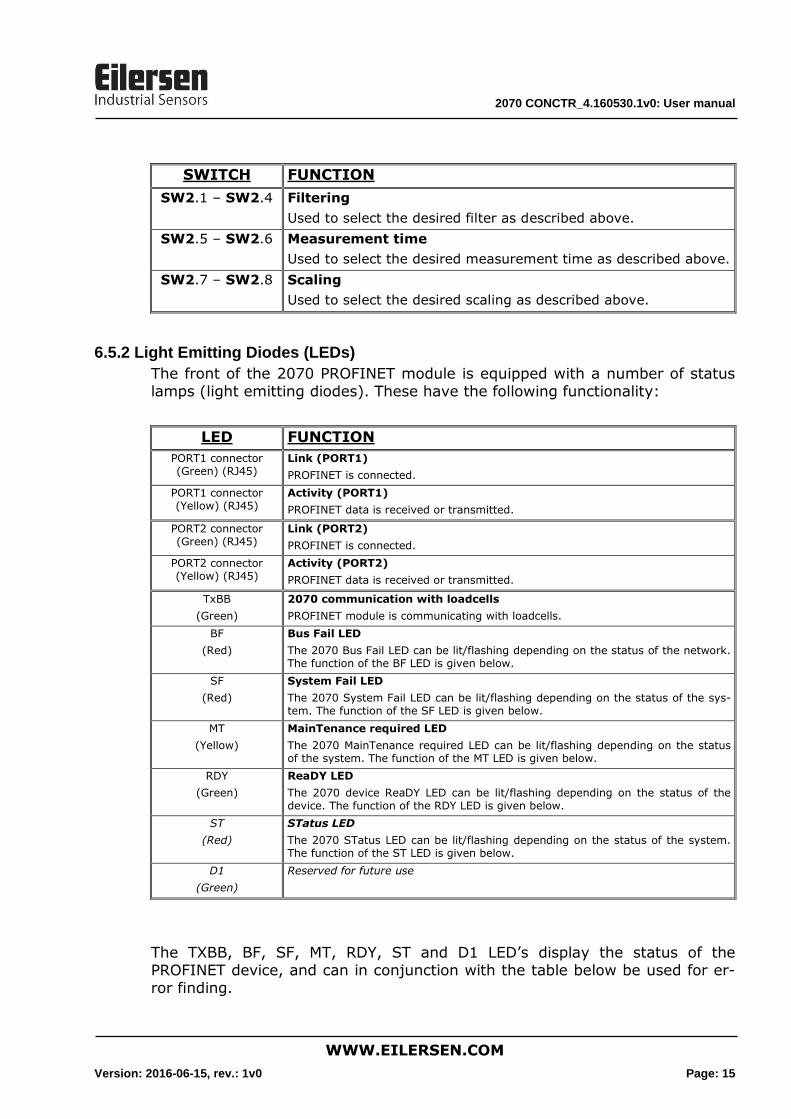
SWITCH FUNCTION
SW2.1 – SW2.4 Filtering
Used to select the desired filter as described above.
SW2.5 – SW2.6 Measurement time
Used to select the desired measurement time as described above.
SW2.7 – SW2.8 Scaling
Used to select the desired scaling as described above.
6.5.2 Light Emitting Diodes (LEDs)
The front of the 2070 PROFINET module is equipped with a number of status lamps (light emitting diodes). These have the following functionality:
LED FUNCTION
PORT1 connector (Green) (RJ45)
Link (PORT1)
PROFINET is connected.
PORT1 connector (Yellow) (RJ45)
Activity (PORT1)
PROFINET data is received or transmitted.
PORT2 connector (Green) (RJ45)
Link (PORT2)
PROFINET is connected.
PORT2 connector (Yellow) (RJ45)
Activity (PORT2)
PROFINET data is received or transmitted.
TxBB
(Green)
2070 communication with loadcells
PROFINET module is communicating with loadcells.
BF
(Red)
Bus Fail LED
The 2070 Bus Fail LED can be lit/flashing depending on the status of the network. The function of the BF LED is given below.
SF
(Red)
System Fail LED
The 2070 System Fail LED can be lit/flashing depending on the status of the sys-tem. The function of the SF LED is given below.
MT
(Yellow)
MainTenance required LED
The 2070 MainTenance required LED can be lit/flashing depending on the status of the system. The function of the MT LED is given below.
RDY
(Green)
ReaDY LED
The 2070 device ReaDY LED can be lit/flashing depending on the status of the device. The function of the RDY LED is given below.
ST
(Red)
STatus LED
The 2070 STatus LED can be lit/flashing depending on the status of the system. The function of the ST LED is given below.
D1
(Green)
Reserved for future use
The TXBB, BF, SF, MT, RDY, ST and D1 LED’s display the status of the PROFINET device, and can in conjunction with the table below be used for er-ror finding.
2070 CONCTR_4.160530.1v0: User manual
WWW.EILERSEN.COM
Version: 2016-06-15, rev.: 1v0 Page: 16
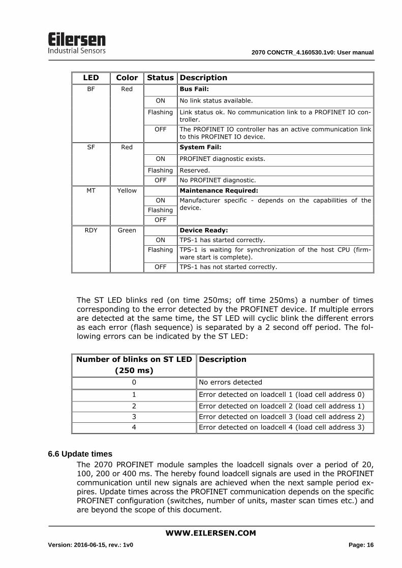
LED Color Status Description
BF Red Bus Fail:
ON No link status available.
Flashing Link status ok. No communication link to a PROFINET IO con-troller.
OFF The PROFINET IO controller has an active communication link
to this PROFINET IO device.
SF Red System Fail:
ON PROFINET diagnostic exists.
Flashing Reserved.
OFF No PROFINET diagnostic.
MT Yellow Maintenance Required:
ON Manufacturer specific - depends on the capabilities of the device. Flashing
OFF
RDY Green Device Ready:
ON TPS-1 has started correctly.
Flashing TPS-1 is waiting for synchronization of the host CPU (firm-
ware start is complete).
OFF TPS-1 has not started correctly.
The ST LED blinks red (on time 250ms; off time 250ms) a number of times
corresponding to the error detected by the PROFINET device. If multiple errors are detected at the same time, the ST LED will cyclic blink the different errors
as each error (flash sequence) is separated by a 2 second off period. The fol-lowing errors can be indicated by the ST LED:
Number of blinks on ST LED
(250 ms)
Description
0 No errors detected
1 Error detected on loadcell 1 (load cell address 0)
2 Error detected on loadcell 2 (load cell address 1)
3 Error detected on loadcell 3 (load cell address 2)
4 Error detected on loadcell 4 (load cell address 3)
6.6 Update times
The 2070 PROFINET module samples the loadcell signals over a period of 20, 100, 200 or 400 ms. The hereby found loadcell signals are used in the PROFINET
communication until new signals are achieved when the next sample period ex-pires. Update times across the PROFINET communication depends on the specific PROFINET configuration (switches, number of units, master scan times etc.) and
are beyond the scope of this document.
2070 CONCTR_4.160530.1v0: User manual
WWW.EILERSEN.COM
Version: 2016-06-15, rev.: 1v0 Page: 17
7) Appendices
7.1 Appendix A – PROFINET Configuration tips
7.1.1 MAC addresses
The MAC addresses of the 2070 PROFINET module are noted on a label on the
side of the 2070 module. The MAC addresses of the 2070 module are preset to unique values within the Eilersen Electric A/S range.
7.1.2 GSDML file
The supplied GSDML can be used to configure the PROFINET master to com-
municate with the 2070 PROFINET module.
Please note that on a Siemens SIMATIC STEP 7 software platform, once the GSDML file has been imported, the imported 2070 PROFINET module will nor-
mally be placed in the following location of the “Hardware catalog”:
Other field devices \ PROFINET IO \ I/O \ Eilersen Electric \ 2x70 CONCTR_4
7.1.3 Factory settings
Upon delivery the 2070 PROFINET module contains the following default facto-ry settings:
Device Name: d2x70
IP Address: 192.168.1.199
Subnet Mask: 255.255.255.0
Default Gateway: 192.168.1.254
Vendor ID: 840 (0x348)
Device Type: D2x70
7.1.4 Setting DeviceName, IP Address etc.
The default factory settings of the 2070 PROFINET module, such as device name (d2x70) and IP address (192.168.1.199) etc., must be changed accord-
ing to the actual PROFINET configuration.
Please note that on a Siemens SIMATIC STEP 7 software platform (TiA Portal), this is normally done under “Online Access” where the different node parame-
ters (MAC address, IP address, DeviceName etc.) can be viewed and possibly changed.
7.1.5 Data sizes
The amount of data exchanged between the PROFINET master and the 2070 PROFINET module is specified in the GSDML file. This application with the
software specified on the front page of the manual uses 26 input bytes and 2
2070 CONCTR_4.160530.1v0: User manual
WWW.EILERSEN.COM
Version: 2016-06-15, rev.: 1v0 Page: 18
output bytes. Please note that in this application the 2 output bytes are actual-
ly NOT used.
NOTE: Please beware that the terms “input” and “output” may be confusing
and are used differently from vendor to vendor. Throughout this manual, these terms are always from the PROFINET masters (PLC’s) point of view. Therefore, the data from the 2070 module to the PLC are referred to as “in-
put” data, while the data from the PLC to the 2070 module are referred to as “output” data.
7.2 Appendix B – Internal Features
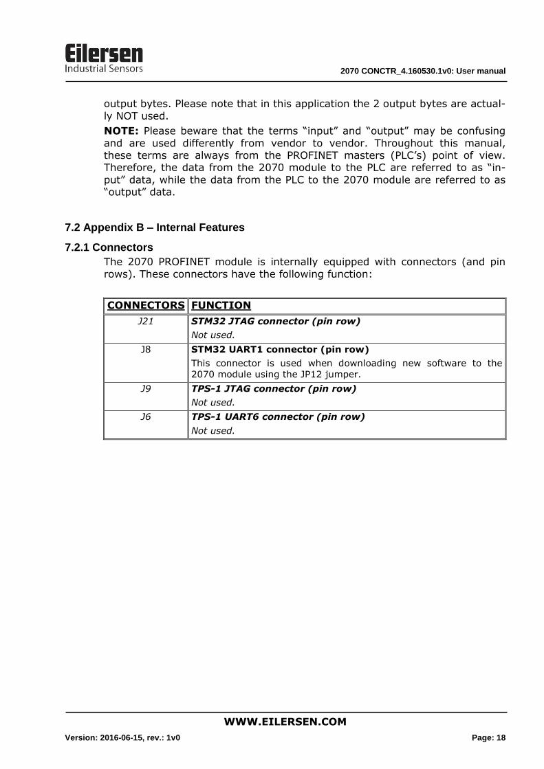
7.2.1 Connectors
The 2070 PROFINET module is internally equipped with connectors (and pin
rows). These connectors have the following function:
CONNECTORS FUNCTION
J21 STM32 JTAG connector (pin row)
Not used.
J8 STM32 UART1 connector (pin row)
This connector is used when downloading new software to the
2070 module using the JP12 jumper.
J9 TPS-1 JTAG connector (pin row)
Not used.
J6 TPS-1 UART6 connector (pin row)
Not used.
2070 CONCTR_4.160530.1v0: User manual
WWW.EILERSEN.COM
Version: 2016-06-15, rev.: 1v0 Page: 19
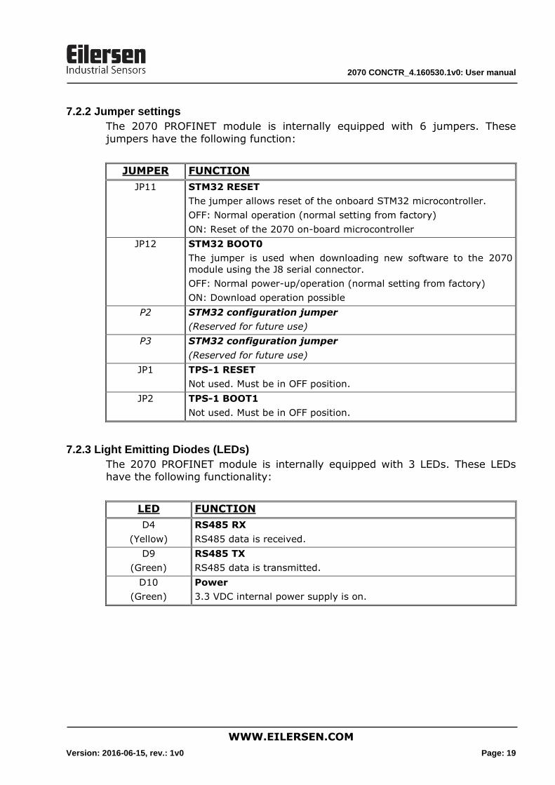
7.2.2 Jumper settings
The 2070 PROFINET module is internally equipped with 6 jumpers. These
jumpers have the following function:
JUMPER FUNCTION
JP11 STM32 RESET
The jumper allows reset of the onboard STM32 microcontroller.
OFF: Normal operation (normal setting from factory)
ON: Reset of the 2070 on-board microcontroller
JP12 STM32 BOOT0
The jumper is used when downloading new software to the 2070
module using the J8 serial connector.
OFF: Normal power-up/operation (normal setting from factory)
ON: Download operation possible
P2 STM32 configuration jumper
(Reserved for future use)
P3 STM32 configuration jumper
(Reserved for future use)
JP1 TPS-1 RESET
Not used. Must be in OFF position.
JP2 TPS-1 BOOT1
Not used. Must be in OFF position.
7.2.3 Light Emitting Diodes (LEDs)
The 2070 PROFINET module is internally equipped with 3 LEDs. These LEDs have the following functionality:
LED FUNCTION
D4
(Yellow)
RS485 RX
RS485 data is received.
D9
(Green)
RS485 TX
RS485 data is transmitted.
D10
(Green)
Power
3.3 VDC internal power supply is on.
2070 CONCTR_4.160530.1v0: User manual
WWW.EILERSEN.COM
Version: 2016-06-15, rev.: 1v0 Page: 20
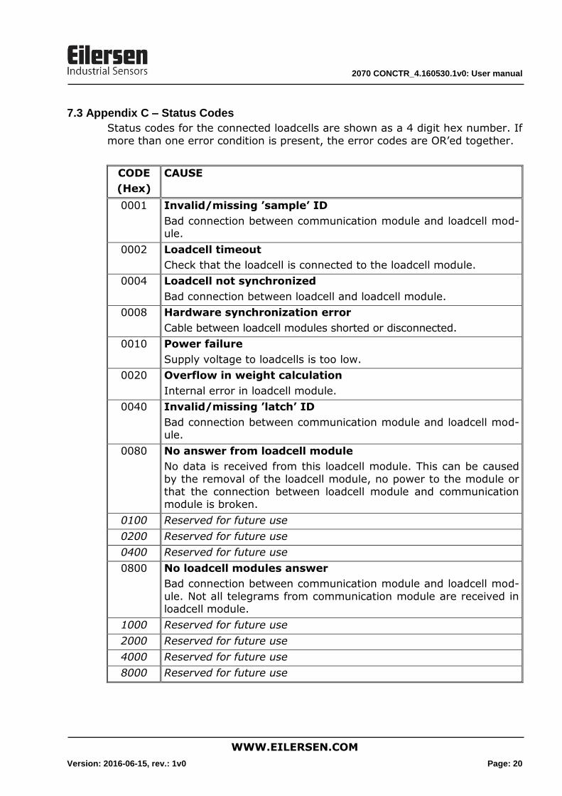
7.3 Appendix C – Status Codes
Status codes for the connected loadcells are shown as a 4 digit hex number. If
more than one error condition is present, the error codes are OR’ed together.
CODE
(Hex)
CAUSE
0001 Invalid/missing ’sample’ ID
Bad connection between communication module and loadcell mod-ule.
0002 Loadcell timeout
Check that the loadcell is connected to the loadcell module.
0004 Loadcell not synchronized
Bad connection between loadcell and loadcell module.
0008 Hardware synchronization error
Cable between loadcell modules shorted or disconnected.
0010 Power failure
Supply voltage to loadcells is too low.
0020 Overflow in weight calculation
Internal error in loadcell module.
0040 Invalid/missing ’latch’ ID
Bad connection between communication module and loadcell mod-ule.
0080 No answer from loadcell module
No data is received from this loadcell module. This can be caused
by the removal of the loadcell module, no power to the module or that the connection between loadcell module and communication module is broken.
0100 Reserved for future use
0200 Reserved for future use
0400 Reserved for future use
0800 No loadcell modules answer
Bad connection between communication module and loadcell mod-
ule. Not all telegrams from communication module are received in loadcell module.
1000 Reserved for future use
2000 Reserved for future use
4000 Reserved for future use
8000 Reserved for future use