2068 ieee transactions on wireless …nextgenwrl/papers/mukhopadhyay_2013_twc.pdf · mpr mac...
TRANSCRIPT

2068 IEEE TRANSACTIONS ON WIRELESS COMMUNICATIONS, VOL. 12, NO. 5, MAY 2013
Design and Analysis of anAcknowledgment-Aware Asynchronous
MPR MAC Protocol for Distributed WLANsArpan Mukhopadhyay, Neelesh B. Mehta, Senior Member, IEEE, and Vikram Srinivasan, Member, IEEE
Abstract—Multi-packet reception (MPR) promises significantthroughput gains in wireless local area networks (WLANs) byallowing nodes to transmit even in the presence of ongoingtransmissions in the medium. However, the medium accesscontrol (MAC) layer must now be redesigned to facilitate –rather than discourage – these overlapping transmissions. Weinvestigate asynchronous MPR MAC protocols, which success-fully accomplish this by controlling the node behavior basedon the number of ongoing transmissions in the channel. Theprotocols use the backoff timer mechanism of the distributedcoordination function, which makes them practically appealing.We first highlight a unique problem of acknowledgment delays,which arises in asynchronous MPR, and investigate a solutionthat modifies the medium access rules to reduce these delays andincrease system throughput in the single receiver scenario. Wedevelop a general renewal-theoretic fixed-point analysis that leadsto expressions for the saturation throughput, packet droppingprobability, and average head-of-line packet delay. We also modeland analyze the practical scenario in which nodes may incorrectlyestimate the number of ongoing transmissions.
Index Terms—Cross-layer design, medium access control,multi-packet reception, wireless local area network, IEEE 802.11,fixed-point analysis, timer backoff.
I. INTRODUCTION
CONVENTIONAL wireless local area networks(WLANs), which use the IEEE 802.11 distributed
coordination function (DCF) [1] and its enhancementsas medium access control (MAC) protocols, are facingincreasing demands for higher data rates and higher systemthroughput. Conventionally, a layered approach is adopted indesigning the physical (PHY) and MAC layers. For example,the DCF MAC uses carrier sense multiple access (CSMA)with collision avoidance (CA) to discourage time-overlappingtransmissions by multiple users in the uplink channel fromthe nodes to the access point (AP). This is accomplished bymaking the nodes freeze their backoff timers anytime theysense an ongoing transmission in the channel.
Manuscript received March 23, 2012; revised August 11 and December21, 2012, and February 13, 2013; accepted February 15, 2013. The associateeditor coordinating the review of this paper and approving it for publicationwas W. Choi.
A. Mukhopadhyay is with the Dept. of Electrical and Computer Eng., Univ.of Waterloo, Canada (e-mail: [email protected]).
N. B. Mehta is with the Dept. of Electrical Communication Eng., IndianInstitute of Science (IISc), Bangalore (e-mail: [email protected]).
V. Srinivasan is with Bell Labs Research, Alcatel-Lucent, Bangalore, India(e-mail: [email protected]).
A part of this work has been presented at the 2012 IEEE Global Commu-nications Conf. (Globecom).
Digital Object Identifier 10.1109/TWC.2013.032513.120429
With the advent of advanced signal processing techniquesbased on code division multiple access (CDMA), succes-sive interference cancellation (SIC), or multiple antennas,today’s wireless receivers are capable of decoding multiplesimultaneous transmissions. This has been referred to as themulti-packet reception (MPR) capability [2]–[9]. Instead ofdiscouraging overlapping transmissions, the MAC layer mustnow facilitate their occurrence in order to benefit from MPR.At the same time, the MAC should retain the distributedmanner in which nodes access the medium, as this is a keyreason behind the success of the IEEE 802.11 DCF MAC.
A. Related Literature
We now summarize some key papers on MPR and ascertaintheir efficacy, distributed nature, and suitability for an IEEE802.11-type DCF MAC. MPR was first considered in [8], [10]for slotted ALOHA, but CSMA was not modeled. An adaptiveMAC protocol for MPR that maximizes the expected numberof successfully transmitted packets per slot and also takesinto account quality of service requirements was proposedin [5]. A simpler variant based on collision resolution wasproposed in [11]. A similar objective was achieved in [4]for space division multiple access systems (SDMA) that usemultiple antenna APs. However, these protocols require acentral controller that selects an optimal set of users that accessthe channel in each slot.
MPR with CSMA was analyzed in [12], [13]. In [12], anode uses channel sensing to determine whether the channelcan support more ongoing transmissions and then transmitsaccordingly. However, neither acknowledgments (ACKs) northe timer-based backoff mechanism of IEEE 802.11 weremodeled. In [6], [14], timer-based backoff protocols for IEEE802.11 WLANs with MPR were considered. However, asynchronous scenario, in which transmissions by multiplenodes can only start simultaneously, is assumed. This isachieved by modifying the request-to-send (RTS) and clear-to-send (CTS) handshaking procedure of IEEE 802.11. Anode does not transmit once it senses the channel to bebusy regardless of the number of ongoing transmissions,which limits the gains possible from using MPR. Further, theoverheads of the RTS/CTS procedure have led to its limitedadoption in practice. Therefore, it is worthwhile investigatingasynchronous MPR MAC protocols that allow overlappingpacket transmissions to start at different times. An MPRMAC protocol, that encourages two asynchronous RTS packet
1536-1276/13$31.00 c© 2013 IEEE

MUKHOPADHYAY et al.: DESIGN AND ANALYSIS OF AN ACKNOWLEDGMENT-AWARE ASYNCHRONOUS MPR MAC PROTOCOL . . . 2069
transmissions was proposed in [15] and a two node networkwas analyzed.
A generic, distributed asynchronous MPR model, whichexploited the fact that a multiple antenna node can estimatethe number of ongoing transmissions, was recently analyzedby Babich and Comisso in [16] using Markov chains. Init, a node continues to decrement its backoff timer andeventually transmits even when it senses the channel to bebusy – so long as the number of ongoing transmissions is lessthan or equal to a threshold; else, it freezes its timer. Theprotocol was analyzed without any limitation on the numberof receivers [17]. However, ACKs were not modeled; it wasimplicitly assumed that a node knows whether its transmissionhas succeeded or not immediately after transmitting its packet.Further, nodes were assumed to perfectly estimate the numberof ongoing transmissions.
The use of MPR in an asynchronous set up can, in fact,delay the transmission of an ACK by the AP. This is be-cause packet transmissions by different nodes can now startat different time slots and overlap without any idle periodin between. Consequently, the AP will have to continue toreceive packets even after a particular node completes itstransmission. As a result, the transmission of an ACK bythe AP, which is a half-duplex node, can get significantlydelayed. Since the presence or absence of an ACK makes anode update its backoff parameters, ACK delays can degradesystem throughput and increase packet transmission delays.
B. Contributions
The paper makes several contributions on the followingaspects of asynchronous MPR MAC.
Protocol Design: The paper first points out that in anasynchronous MPR MAC protocol, ACKs may get delayed.This delay in the reception of ACKs, which is absent inconventional DCF and synchronous MPR protocols, can de-grade the system performance. We propose and compare twoasynchronous MPR MAC protocols, both of which incorporateACKs in the single receiver scenario. The first protocol is ourown interpretation of how ACKs can be incorporated in themodel analyzed in [16], and serves as a benchmark. In thesecond protocol, the MAC rules, which determine when a nodeshould freeze or decrement its backoff timer, are modifiedto reduce the ACK delays and increase system throughput.In it, nodes freeze their backoff timers once the number oftransmissions in the channel reaches the MPR capability of theAP or once any node completes the transmission of its packet.This ensures that a node, which has just finished transmittingits packet, waits for no more than one packet duration toreceive an ACK.
Modeling imperfect estimation: Another contribution is atractable modeling of the practical scenario where the nodesincorrectly estimate the number of ongoing transmissions inthe channel. We show that the first and the second protocolsare quite robust to imperfect estimation. Several MPR-specificimplementation issues are also discussed.
Analysis: Finally, the paper develops a general, renewal-theoretic fixed-point analysis of the second asynchronousMPR MAC protocol that explicitly takes ACKs into consid-eration. The analysis can handle the ideal case with perfect
estimates and the practical case with imperfect estimates.Analytical expressions for the saturation throughput, packetdropping probability, and average head-of-line packet delayare derived. Saturation throughput is an important performancemeasure for a MAC protocol and has been extensively ana-lyzed in the literature on conventional 802.11 DCF and MPR.It gives a limit on the system throughput in heavy trafficloads [6], [14], [15], [18], [19]. In some cases, it also providesa sufficient condition for stability of queues at the nodes [20].The average head-of-line delay affects the performance of thehigher layers of the protocol stack and is the first step in aqueuing delay analysis for non-saturated traffic [21], [22].
The renewal-theoretic approach developed in this paper isdifferent from the Markovian analysis used in [16], [18]. Forexample, in our analysis, packet lengths need not follow thememoryless geometric probability distribution, which breaksdown under heavy traffic load conditions when a packet suffersmany retransmissions [16]. The effect of packet dropping aftera finite number of retransmissions is also incorporated. Ouranalysis also generalizes the renewal-theoretic analysis thatwas developed in [19] for conventional DCF.
Performance benchmarking: We also extensively bench-mark the saturation throughput, head-of-line packet delay, andpacket dropping probability of the two asynchronous MPRMAC protocols and conventional DCF. This is done for bothideal and imperfect estimation.
The paper is organized as follows. Section II sets up thesystem model and the asynchronous MPR MAC protocols,which are then analyzed in Section III. Imperfect estimationis modeled and analyzed in Section IV. Simulations results inSection V are followed by our conclusions in Section VI.
II. SYSTEM MODEL
A. System Model
Consider the uplink of a WLAN, in which the AP acts asthe central node and n surrounding nodes need to transmitpackets directly to the AP. The following MPR data receptionmodel is assumed, along the lines of [6], [14], [16]. The APcan successfully decode all the overlapping transmissions aslong as the number of overlapping transmissions is less thanor equal to L. If more than L overlapping transmissions occur,then the AP fails to decode the transmissions and a collisionis said to occur. Here, L is called the MPR capability.1
Further, it is assumed that a node can correctly estimatewhether the number of ongoing transmissions in the channelis 0, 1, . . . , L− 1, or whether it is greater than or equal to L.Techniques to estimate the number of ongoing transmissionsand the effect of imperfect estimates are discussed later inSection IV.
Each node follows the timer-based binary exponential back-off scheme of conventional DCF, and a packet is droppedby a node after K + 1 failed transmission attempts. Beforeeach transmission attempt, a node selects its backoff period ininteger multiples of a slot duration δ. The multiple is uniformlychosen from the set {0, 1, . . . , w − 1}, where w is calledthe contention window. It depends on the number of failed
1This MPR reception capability based model can also be expressed in termsof MPR-matrix model of [2], [5], [8], and [9].
2070 IEEE TRANSACTIONS ON WIRELESS COMMUNICATIONS, VOL. 12, NO. 5, MAY 2013
DATA
DATA
DATA
A
B
C
Backofffreeze
Re
ceiv
eCu
mul
ativ
e
AC
K
TDIFS
TSIFS
Wait to start ACK-timeout
Wait to start ACK-timeout
TSIFS
TSIFS
Backoffdecrement
TDIFS
TDIFS
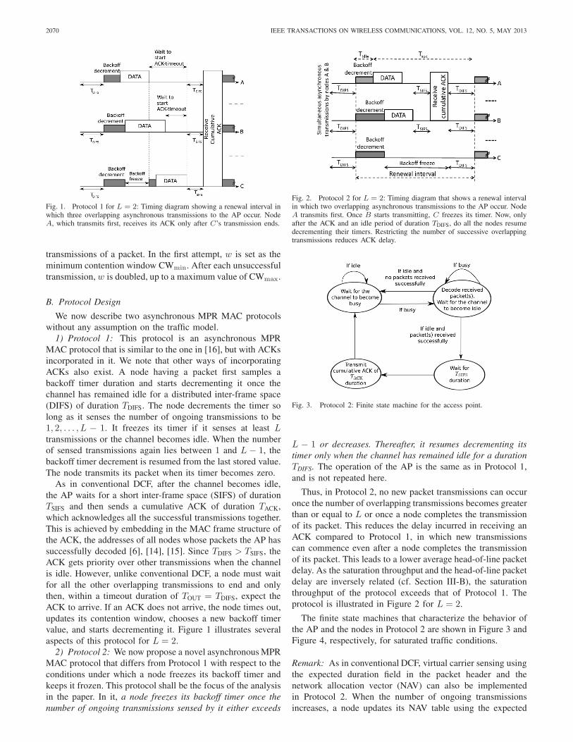
Fig. 1. Protocol 1 for L = 2: Timing diagram showing a renewal interval inwhich three overlapping asynchronous transmissions to the AP occur. NodeA, which transmits first, receives its ACK only after C’s transmission ends.
transmissions of a packet. In the first attempt, w is set as theminimum contention window CWmin. After each unsuccessfultransmission, w is doubled, up to a maximum value of CWmax.
B. Protocol Design
We now describe two asynchronous MPR MAC protocolswithout any assumption on the traffic model.
1) Protocol 1: This protocol is an asynchronous MPRMAC protocol that is similar to the one in [16], but with ACKsincorporated in it. We note that other ways of incorporatingACKs also exist. A node having a packet first samples abackoff timer duration and starts decrementing it once thechannel has remained idle for a distributed inter-frame space(DIFS) of duration TDIFS. The node decrements the timer solong as it senses the number of ongoing transmissions to be1, 2, . . . , L − 1. It freezes its timer if it senses at least Ltransmissions or the channel becomes idle. When the numberof sensed transmissions again lies between 1 and L − 1, thebackoff timer decrement is resumed from the last stored value.The node transmits its packet when its timer becomes zero.
As in conventional DCF, after the channel becomes idle,the AP waits for a short inter-frame space (SIFS) of durationTSIFS and then sends a cumulative ACK of duration TACK,which acknowledges all the successful transmissions together.This is achieved by embedding in the MAC frame structure ofthe ACK, the addresses of all nodes whose packets the AP hassuccessfully decoded [6], [14], [15]. Since TDIFS > TSIFS, theACK gets priority over other transmissions when the channelis idle. However, unlike conventional DCF, a node must waitfor all the other overlapping transmissions to end and onlythen, within a timeout duration of TOUT = TDIFS, expect theACK to arrive. If an ACK does not arrive, the node times out,updates its contention window, chooses a new backoff timervalue, and starts decrementing it. Figure 1 illustrates severalaspects of this protocol for L = 2.
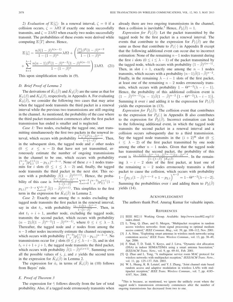
2) Protocol 2: We now propose a novel asynchronous MPRMAC protocol that differs from Protocol 1 with respect to theconditions under which a node freezes its backoff timer andkeeps it frozen. This protocol shall be the focus of the analysisin the paper. In it, a node freezes its backoff timer once thenumber of ongoing transmissions sensed by it either exceeds
Fig. 2. Protocol 2 for L = 2: Timing diagram that shows a renewal intervalin which two overlapping asynchronous transmissions to the AP occur. NodeA transmits first. Once B starts transmitting, C freezes its timer. Now, onlyafter the ACK and an idle period of duration TDIFS, do all the nodes resumedecrementing their timers. Restricting the number of successive overlappingtransmissions reduces ACK delay.
Fig. 3. Protocol 2: Finite state machine for the access point.
L − 1 or decreases. Thereafter, it resumes decrementing itstimer only when the channel has remained idle for a durationTDIFS. The operation of the AP is the same as in Protocol 1,and is not repeated here.
Thus, in Protocol 2, no new packet transmissions can occuronce the number of overlapping transmissions becomes greaterthan or equal to L or once a node completes the transmissionof its packet. This reduces the delay incurred in receiving anACK compared to Protocol 1, in which new transmissionscan commence even after a node completes the transmissionof its packet. This leads to a lower average head-of-line packetdelay. As the saturation throughput and the head-of-line packetdelay are inversely related (cf. Section III-B), the saturationthroughput of the protocol exceeds that of Protocol 1. Theprotocol is illustrated in Figure 2 for L = 2.
The finite state machines that characterize the behavior ofthe AP and the nodes in Protocol 2 are shown in Figure 3 andFigure 4, respectively, for saturated traffic conditions.
Remark: As in conventional DCF, virtual carrier sensing usingthe expected duration field in the packet header and thenetwork allocation vector (NAV) can also be implementedin Protocol 2. When the number of ongoing transmissionsincreases, a node updates its NAV table using the expected

MUKHOPADHYAY et al.: DESIGN AND ANALYSIS OF AN ACKNOWLEDGMENT-AWARE ASYNCHRONOUS MPR MAC PROTOCOL . . . 2071
If the number of sensed
transmissionsbecomes
greater than orequal to L
or decreases
Fig. 4. Protocol 2: Finite state machine for a node under saturated trafficcondition.
duration field of the most recent packet that was transmitted.2
A node can stop sensing the channel once the number oftransmissions reaches L or it starts decreasing. Such virtualcarrier sensing is not as easy in Protocol 1, which allowsnew packet transmissions to start anytime so long as the totalnumber of ongoing transmissions lies between 1 and L− 1.
Remark: In Protocol 2, channel estimation can be performedat the AP using training symbols in the preambles of each ofthe received data packets. The reader is referred to the exten-sive survey of channel estimation issues and techniques in [23]and to the discussion of MPR-specific channel estimation is-sues in [2]. In [24], it was shown that the asynchronous natureof the interference in the MPR MAC protocol even affects theoptimal placement of pilots inside a packet. However, consid-erable work remains to be done on the problem of estimationwith asynchronous packets. Modeling and analyzing its effectis beyond the scope of the paper.
III. ANALYSIS
We now analyze Protocol 2 in saturated traffic conditions,in which the transmission queue at each node is alwaysnon-empty. Data loss due to packet errors is assumed to benegligible and a transmitted packet is assumed to be receivedsuccessfully unless it is involved in a collision.
To get compact analytical results, we assume that thetransmission duration of a data packet is λ slots, and thatthe transmission rate is fixed at Ω, as has also been assumedin [18], [19]. Notice that fixed length packets cannot be easilyanalyzed using the Markovian approach of [16]. Extension tothe scenario, where the packet lengths are random, is discussedat the end of this section. Further, we analyze the L = 2
2If multiple packet transmissions start at the same time, then the maximumof the expected duration fields of the packets is used by the sensing node.
case, as was also done in [15]. The analysis can be extendedto cover the general L ≥ 2 case. However, the expressionsbecome more involved given the larger number of possibletransmission scenarios that can occur. Due to space constraintsand given the limited additional intuition provided by thegeneral scenario, we do not discuss it in this paper.
As all the nodes use the same backoff parameters, theirbehaviors are statistically identical. Hence, we make thefollowing decoupling approximations, which enable a fixed-point analysis [18], [19]:
1) Each transmitted packet suffers a collision with a prob-ability γ, which is independent of all other packettransmissions and the number of its retransmissions.We shall refer to γ as the conditional packet collisionprobability.
2) Each node attempts a transmission in a slot in whichit can transmit with a probability β, which is inde-pendent of all other nodes. We shall refer to β as theattempt rate.
Node-specific renewal process: Consider a given node,which we henceforth call the tagged node. Let Aj and Bj
respectively denote the number of attempts and total backoffduration (in slots) needed by the tagged node to transmit its j th
packet. Let us consider the process formed by extracting onlythe times at which the tagged node is in its backoff phase, i.e.,it is decrementing its backoff timer. From the first assumptionand the fact that the tagged node uses the same backoff param-eters for all its packets, it can be inferred that the sequences(Aj)j≥1, (Bj)j≥1, and (Aj , Bj)j≥1, are all independent andidentically distributed (i.i.d) [19]. Hence, the backoff processof a tagged node is a renewal process with renewal lifetimesBj , j ≥ 1, and the renewal epochs are the time instants atwhich the node starts the final transmission of its j th packet.If we consider Aj , j ≥ 1, as the reward gained in the j th
renewal interval, then from the renewal reward theorem [25],we have β =
E[Aj ]E[Bj ]
, where E [·] denotes expectation.
System-wide renewal process: Consider the aggregate at-tempt process by all the n nodes. Due to the decouplingassumption, the aggregate attempt process is another renewalprocess. As shown in Figure 2, the renewal epochs of thisprocess are the instants at which all the nodes start decre-menting their backoff timers. For the rest of the paper, unlessmentioned otherwise, the term renewal interval shall refer tothe renewal interval of the system-wide renewal process.
Unlike conventional DCF, more than one packet can gettransmitted in a renewal interval. We, therefore, first define thefollowing terminology. For j ∈ {1, 2}, a transmitted packet iscalled the j th packet in a renewal interval if there are alreadyj − 1 ongoing packet transmissions in the channel when itstransmission commences.
Lemma 1: Given that a tagged node transmits in a renewalinterval, the probability α that its packet is the first packet inthe renewal interval is α = K1(β)
K1(β)+K2(β), where Ki(β) is the
unconditional probability that the tagged node transmits the

2072 IEEE TRANSACTIONS ON WIRELESS COMMUNICATIONS, VOL. 12, NO. 5, MAY 2013
ith packet in a renewal interval. Further,
K1(β) =β
1− (1− β)n, (1)
K2(β) =(n− 1)β2(1− β)n−1(1− (1− β)(λ−1)(n−1))
(1 − (1− β)n)(1− (1 − β)n−1).
(2)
Proof: The proof is relegated to Appendix A.Thus, given that a tagged node has transmitted in a renewalinterval, the probability that its packet is the second packet inthe renewal interval is 1− α.
Theorem 1: The conditional packet collision probability,γ, as a function of β is given by
γ � Γ(β) = αP1(β) + (1− α)P2(β), (3)
where Pi(β), for i = 1, 2, denotes the probability that a packetsuffers a collision given that it is the ith transmitted packet ina renewal interval. Further,
P1(β) =
(1− (1− β)n−1 − (n− 1)β(1− β)n−2
)1− (1− β)n−1
×(1− (1− β)λ(n−1)
), (4)
P2(β) = 1− (1− β)n−2. (5)
The attempt rate, β, as a function of γ is given by β �G(γ) = 1+γ+γ2+···+γK
b0+γb1+γ2b2+···+γKbK, where bk denotes the mean
backoff duration (in slots) before the (k + 1)th transmissionattempt of a packet.
Proof: The proof is relegated to Appendix B.Hence, combining Lemma 1 and Theorem 1 results in the
following fixed-point equation:
γ = Γ(G(γ)). (6)
Since Γ(G(γ)) is a continuous mapping in γ from the closedset [0, 1] to itself, Brouwer’s fixed-point theorem [26] guaran-tees the existence of a fixed-point in the range. Solving thisequation numerically yields γ. Theorem 1 directly yields β.3
A. Saturation Throughput
Let ζ denote the amount of successfully transmitted data atthe end of a renewal interval of duration T . From the renewalreward theorem [25], the saturation throughput, S, is given byS = E[ζ]
E[T ] . We now develop expressions for E [ζ] and E [T ].As shown in Figure 2, a renewal interval of length T startswith an idle period of duration Tidle. It is followed by a busyperiod Tbusy, in which one or more packets and a cumulativeACK (if success occurs) are transmitted. The busy period endsonce the channel has been idle for the duration TDIFS.
Depending on whether a success or a collision has occurredin the renewal interval, we refer to the busy time periodfollowing the idle period as a success period of duration Tsuc
or a collision period of duration Tcol, respectively. Further, letTmin
col and Tminsuc denote the minimum values of Tcol and Tsuc,
respectively. It can be seen that Tmincol = λδ + TDIFS, which
3In our simulations, we have observed that the fixed-point is unique for theparameters of interest. However, proving uniqueness remains a challengingtask.
occurs when at least three packets of length λδ are transmittedsimultaneously at the end of the idle period. Similarly, we haveTmin
suc = λδ + TSIFS + TACK + TDIFS.Theorem 2: The expected duration of the renewal interval
is E [T ] = E [Tidle] + Dcol + Dsuc, where Dcol and Dsuc
are the contributions from the collision and success events,respectively. Further, E [Tidle] =
11−(1−β)n ,
Dcol =
[1− (1− β)n − nβ(1 − β)n−1
1− (1− β)n
−n(n− 1)β2(1− β)n−2
2 (1− (1− β)n)
]Tmin
col
+nβ (1− β)
n−1 (1− (1− β)n−1 − (n− 1)β(1 − β)n−2
)(1− (1− β)n) (1− (1− β)n−1)
× [Ψ1Tmincol +Ψ2δ
], (7)
Dsuc =n(n− 1)β2(1− β)n−2 + 2nβ(1− β)λ(n−1)
2 (1− (1− β)n)Tmin
suc
+n(n− 1)β2(1− β)2n−3
(1− (1− β)n) (1− (1− β)n−1)
[Ψ1T
minsuc +Ψ2δ
], (8)
where Ψ1 = 1 − (1 − β)(λ−1)(n−1) and Ψ2 =1−(1−β)(λ−1)(n−1)(λ−(λ−1)(1−β)n−1)
(1−(1−β)n−1) .The average number of bits transmitted in a renewal interval
is given by
E [ζ] = λδΩ
(n(n− 1)β2(1− β)n−2 + nβ(1 − β)λ(n−1)
1− (1− β)n
+2n(n− 1)β2(1− β)n−2
[(1 − β)n−1 − (1− β)λ(n−1)
](1 − (1− β)n−1)(1− (1 − β)n)
).
(9)
Proof: The proof is relegated to Appendix C.Hence, the expression for the saturation throughput follows
directly from Theorem 2.
B. Packet Dropping Prob. and Average Head-of-line Delay
A packet is discarded by a node if it suffers K+1 collisions.By our first decoupling approximation, a packet collides witha probability γ, which is independent of the number of itsretransmission attempts. Consequently, the packet droppingprobability is simply γK+1.
The head-of-line packet delay D is the average time spentby a packet in the head-of-queue position before it getstransmitted successfully or gets dropped after K + 1 failedtransmission attempts. To evaluate D, we first note that thepacket dropping probability, γK+1, is small unless the channelis heavily congested. Therefore, almost all the packets areeventually successfully transmitted. Hence, D is approxi-mately equal to the average time taken by a node to success-fully transmit a packet. Since S is the saturation throughput(in bits) and each packet carries a payload of Ωλδ bits, thenumber of data packets that are successfully transmitted perunit time is S
λδΩ . Thus, the number of successfully transmitteddata packets per unit time per node is S
nλδΩ . Therefore, theaverage head-of-line packet delay is D ≈ nλδΩ
S .

MUKHOPADHYAY et al.: DESIGN AND ANALYSIS OF AN ACKNOWLEDGMENT-AWARE ASYNCHRONOUS MPR MAC PROTOCOL . . . 2073
Remark: The fixed-point analysis presented in this section canbe extended to handle the scenario where the packet lengthsare random variables. It can be shown that the general expres-sions for K2(β) and P1(β) are obtained by taking expectationsof (2) and (5), respectively, with respect to the distributionof the packet lengths. The expressions for Dcol, Dsuc, andE [ζ] can be derived similarly by summing over all possiblerealizations of packet lengths of the first and second packetsin a renewal interval. Other expressions remain unchanged.
IV. EFFECT OF IMPERFECT CHANNEL ESTIMATION
In practice, the nodes need to estimate the number ofongoing transmissions in the channel. Several techniques havebeen developed in the literature for this purpose [27]. Wediscuss below a technique based on the eigen-decompositionof the correlation matrix of the signal received by the antennaarray of a node. The technique can be used if a node isequipped with an array of at least L antennas, which is feasiblein WLANs today [28], [29].
Let a node be equipped with V ≥ L antennas and letthere be U ongoing transmissions in the channel. Also, letyj(t), for j = 1, . . . , V , denote the signal received at thej th antenna of the node. Noises at different array elementsare assumed to be uncorrelated with variance σ2
n. The cor-relation matrix R associated with the received signal vectory(t) = [y1(t), . . . , yV (t)]
T is defined as R = E[y(t)y†(t)
],
where T and † denote transpose and Hermitian transpose,respectively. It can be shown that if U < V then the smallesteigenvalue of R is σ2
n and it has an algebraic multiplicity ofV − U . When U ≥ V (≥ L), R has no eigenvalues equal toσ2n. Thus, by evaluating the multiplicity of the eigenvalue of
R that is equal to σ2n, a node can estimate if the number of
ongoing transmissions is 0, 1, 2, . . . , L− 1 or ≥ L.In practice, since R itself is estimated by averaging a finite
number of samples taken from the output of the antenna array,its smallest V − U eigenvalues need not be exactly equal tothe noise variance. Several papers in the literature, e.g., [30]–[32], solve this problem using approaches based on nestedsequence of hypothesis tests, information-theoretic criteria formodel selection, and ranking and selection theory.
Imperfect estimation model: A key thing to take away fromthis discussion is that the presence of noise and channelpropagation effects can occasionally make a node incorrectlyestimate the number of ongoing transmissions in the channel.This affects the performance of the asynchronous MPR proto-cols whose MAC rules use this estimate. We model imperfectestimation as follows. With probability pi,j , a node estimatesthat there j ongoing transmissions while there actually arei.4 We make the following simplifying assumptions: (1) Anode makes an error independent of the other nodes. This isjustifiable since the channel fades and noise encountered bythe different nodes are independent. (2) Once a node estimatesthe number of transmissions in a slot, its estimate does notchange until the transmitters or the number of transmissionsactually change. This captures the fact that deep fades are
4This abstraction presents a refined probabilistic model for the classicalhidden nodes problem that arises in conventional DCF, in which the nodesthat incorrectly estimate that the number of ongoing transmissions is zero aretreated as hidden nodes.
primarily responsible for incorrect estimation. (3) A nodeperfectly estimates whether the channel is idle or not, i.e.,p0,j = pj,0 = 0, for all j ≥ 1. Similarly, the odds that a node’sestimate of the number of ongoing transmissions is incorrectby more than one are assumed to be negligible, i.e., pi,j = 0if |j − i| ≥ 2, for all i ∈ Z
+. We shall also assume thatpL−1,L = 0. This intuitive model, while not general, providesa tractable method to analyze the effect of imperfect estimates,while capturing the essence of the problem.
As before, we analyze below the L = 2 case. The mainproblem that now arises is that a node can erroneously estimatethe number of ongoing transmissions to be one, while thereare actually two. It, therefore, will continue to decrement itstimer and eventually it may transmit and cause a collision.
A. Analysis with Imperfect Estimation
As in Section III, we use the two classical decouplingapproximations. To distinguish from the perfect estimationcase, we shall denote the attempt rate by β and the condi-tional packet collision probability by γ. It can be shown thatβ = G(γ), where G(·) is as defined in Theorem 1.
We now consider the system-wide renewal process. Due toimperfect estimation, a third, and, in general, a j th packet, forj ≥ 3, can be transmitted in a renewal interval. The j th packetin a renewal interval, for j ≥ 3, is defined as a packet whosetransmission commences erroneously when j − 1 nodes havealready commenced transmission in the interval.
The erroneous third packet transmission can start, for exam-ple, when the previous two transmissions are still ongoing. Itcan also start after the number of transmissions decreases fromtwo to one. This is because the nodes, which had erroneouslyestimated two transmissions to be one, cannot detect thisdecrease and continue to decrement their timers. However,the latter scenario is less probable because, for it to happen,the erroneous node must have a sufficiently large backofftimer value to decrement even after the completion of the firstpacket’s transmission. In Protocol 2, when the estimation erroris small, collisions occur rarely, which makes it less likely fora node to have a large enough contention window. Therefore,we ignore this case and all cases that involve more than oneerroneous packet transmission in a renewal interval.
In order to write compact expressions, we first define thefunction Θ : Z+ → R
+ as Θ(t) = p2,1(1 − β)t + 1− p2,1. Itdenotes the probability that a node does not transmit during thet slots in which there are already two ongoing transmissionsin the channel.
Lemma 2: Given that a tagged node transmits in a renewalinterval, the probability αi that the packet transmitted by thetagged node is the ith packet in the interval is given by
αi =Ki(β)
K1(β) + K2(β) + K3(β), (10)
where Ki(β), for i = 1, 2, 3, is the unconditional probabilitythat a tagged node transmits the ith packet in a renewal interval.

2074 IEEE TRANSACTIONS ON WIRELESS COMMUNICATIONS, VOL. 12, NO. 5, MAY 2013
Furthermore, K1(β) = K1(β), K2(β) = K2(β), and
K3(β) =n(n− 1)β3(1− β)n−2
2(1− (1− β)n
) λ−2∑i=0
p2,1(1− β)iΘn−3(i)
+(n− 1)(n− 2)β3(1− β)2n−3
1− (1− β)n
×λ−3∑i=0
λ−i−3∑j=0
(1− β)i(n−1)+jp2,1Θn−3(j). (11)
Recall that K1(·) and K2(·) are defined in Lemma 1.Proof: The proof is relegated to Appendix D.
Theorem 3: The packet collision probability, γ, in termsof the attempt rate, β, is given by
γ � Γ(β) = α1P1(β) + α2P2(β) + α3P3(β), (12)
where αi, for i = 1, 2, 3, are given by Lemma 2. Here,Pi(β) denotes the probability that a packet suffers a collisiongiven that it is the ith transmitted packet in a renewal interval.Further,
P1(β) = P1(β) + (n− 1)β(1− β)n−2
×λ−1∑i=0
(1 − β)i(n−1)(1−Θn−2(λ − i− 1)
), (13)
P2(β) = P2(β) +(1− (1 − β)n−1)(1 − β)n−2
1− (1− β)(λ−1)(n−1)
×λ−2∑i=0
(1 − β)i(n−1)(1−Θn−2(λ − i− 2)
), (14)
and P3(β) = 1. Recall that P1(·) and P2(·) are defined inTheorem 1.
Proof: The proof is relegated to Appendix E.Hence, by combining (12) and β = G(γ), we obtain
the desired fixed-point equation in γ. As in ideal channelestimation, the existence of a solution in [0, 1] is guaranteed bythe Brouwer’s fixed-point theorem [26]. Proving uniquenessagain remains an unsolved problem.
B. Throughput
As in Section III-A, it can be shown that the saturationthroughput with imperfect estimation is S = E[ζ]
E[T ] . We nowevaluate E [T ] and E [ζ].
1) Evaluating E [T ]: Recall from Lemma 2 that E [T ] =E [Tidle] +Dcol + Dsuc. As before, E [Tidle] =
1
1−(1−β)n. We
now derive expressions for Dsuc and Dcol.Evaluating Dsuc: Clearly, Tbusy = Tmin
suc when: (i) onlyone node transmits in the renewal interval, or (ii) exactlytwo nodes start transmitting simultaneously at the end of theidle period and no other transmissions occur subsequently.Exactly two nodes can do so only when each of the remainingn − 2 nodes either does not make an error, or makes anerror but does not transmit during the remaining λ − 1 slotsof the first two packets. The probability of this event is
(p2,1(1− β)λ−1 + 1− p2,1
)n−2
= Θn−2(λ− 1). Then,
Pr[Tbusy = Tmin
suc
]=
nβ(1− β)λ(n−1)
1− (1− β)n
+
(n2
)β2(1− β)n−2
1− (1− β)nΘn−2(λ− 1). (15)
The denominator term 1 − (1− β)n arises because of condi-tioning on the event that the idle period has already ended.
Similarly, Tbusy = Tminsuc + kδ when the first and second
transmissions in a renewal interval start 1 ≤ k ≤ λ − 1 slotsapart and no other transmission occurs subsequently. It can beshown that
Pr[Tsuc = Tmin
suc + kδ]=
n(n− 1)β2(1− β)k(n−1)
1− (1 − β)n
× (1 − β)n−2Θn−2(λ− 1− k). (16)
Evaluating Dcol: Along similar lines, Tbusy = Tmincol when at
least three among n nodes start transmitting simultaneously atthe end of the idle period. The probability of this event is
Pr[Tbusy = Tmin
col
]=
1− (1− β)n − nβ(1− β)n−1
1− (1− β)n
−(n2
)β2(1− β)n−2
1− (1− β)n. (17)
Again, Tbusy = Tmincol + kδ when: (i) Exactly two of the n
nodes transmit the first packet in a renewal interval and thethird packet is transmitted erroneously after k slots by at leastone of the remaining n−2 nodes, which can be shown to occurwith probability Θn−2(k−1)−Θn−2(k); or (ii) the first packetis transmitted by a single node, and after k slots at least two ofthe remaining nodes transmit simultaneously; or (iii) the firstand second packets are transmitted l slots (1 ≤ l ≤ k − 1)apart, and the third erroneous transmission occurs k slots afterthe first transmission. The probabilities of these events can becalculated in a manner similar to that discussed above. It canbe shown that
Pr[Tbusy = Tmin
col + kδ]=
(n2
)β2(1− β)n−2
1− (1− β)n
× (Θn−2(k − 1)−Θn−2(k))+
n(n− 1)β2(1 − β)n−2
1− (1− β)n
×[k−1∑l=1
(1 − β)l(n−1)(Θn−2(k − l − 1)−Θn−2(k − l)
)]
+nβ(1− β)k(n−1)
1− (1− β)n(1−(1− β)n−1−(n−1)β(1− β)n−2).
(18)
Combining the above results yields the expressions for Dsuc
and Dcol, and, hence, E [T ].2) Evaluating E [ζ]: As in ideal channel estimation, ζ
equals 0, λδΩ, or 2λδΩ when 0, 1, or 2 packets, respectively,are successfully transmitted in a renewal interval. The prob-abilities of the latter two events are given in (15) and (16).

MUKHOPADHYAY et al.: DESIGN AND ANALYSIS OF AN ACKNOWLEDGMENT-AWARE ASYNCHRONOUS MPR MAC PROTOCOL . . . 2075
TABLE ISIMULATION PARAMETERS
Parameter Notation ValuesSlot duration δ 20 μsDIFS duration TDIFS 50 μsSIFS duration TSIFS 10 μsMinimum contention window size CWmin 32Maximum contention window size CWmax 1024Maximum number of transmissions K + 1 8Packet length λ 400 slotsACK duration (with PHY header) TACK 304 + 48(L − 1) μs
Hence,
E [ζ] = λδΩnβ(1− β)λ(n−1)
1− (1− β)n
+ λδΩn(n− 1)β2(1− β)n−2
1− (1− β)nΘn−2(λ− 1)
+ 2λδΩ
λ−1∑k=1
n(n− 1)β2(1− β)k(n−1)(1− β)n−2
1− (1− β)n
×Θn−2(λ− 1− k). (19)
V. NUMERICAL RESULTS
We now present the results obtained from Monte Carlosimulations that use 50,000 samples. An event-driven plat-form written in the C programming language was built forsimulating the MPR protocols, and provides an independentverification of the analytical results. The platform implementsthe finite state machines of the AP and the nodes that areshown in Figures 3 and 4, respectively. Virtual carrier sensingis not implemented since it does not affect the performancemetrics under consideration. The parameter values used in thesimulations are listed in Table I. The ACK frame length isincreased by 6 bytes for each extra receiver address field toincorporate the cumulative ACK used by MPR. We shall varysome of the parameters over a wide range to investigate thesensitivity of the asynchronous MPR MAC protocols to them.
A. Ideal Estimation
Figure 5 plots the normalized saturation throughput, S/Ω, ofconventional DCF, Protocol 1, and Protocol 2 as a function ofthe number of nodes, n, for different values of L. We observea good match between the analysis and simulation results forthe L = 2 case. We also see that the saturation throughputof Protocol 2 is close to L times that of conventional DCFand is 10-30% more than that of Protocol 1. Allowing forvariable packet lengths in the model could make MPR evenmore rewarding.
Similar results are obtained in Figure 6, which plots theaverage head-of-line packet delay of the protocols as a func-tion of n for various L. This figure shows that the head-of-line packet delay increases almost linearly with the numberof nodes, n. This can be explained by the relation derived inSection III-B and the fact that saturation throughput variesslowly with n. We see that the head-of-line packet delaydecreases as L increases. This is because, for larger L, moretransmission opportunities are available for a node. This more
10 15 20 25 30 35 40 45 500
0.5
1
1.5
2
2.5
3
3.5
4
4.5
Number of nodes, n
Nor
mal
ized
sat
urat
ion
thro
ughp
ut, S
/Ω
Protocol 2Protocol 1
L=3
L=5
L=2
802.11 DCFbasic access
Fig. 5. Saturation throughput as a function of the number of nodes fordifferent values of L. Analysis results for L = 2 for Protocol 2 are shownusing circles (◦).
10 15 20 25 30 35 40 45 500
50
100
150
200
250
Number of nodes, n
Ave
rage
hea
d−of
−lin
e pa
cket
del
ay (
in m
s)
Protocol 2Protocol 1
802.11 DCFbasicaccess
L=2 L=3
L=5
Fig. 6. Average head-of-line packet delay as a function of the number ofnodes n for different values of L. Analysis results for L = 2 for Protocol 2are shown using circles (◦).
than compensates for the additional delay caused by moreoverlapping transmissions in a renewal interval.
To investigate the effect of packet lengths on the perfor-mance of the protocols, we plot in Figure 7 the saturationthroughputs of Protocols 1 and 2 as a function of the packetlength, λ, for different values of L. We again see that Proto-col 2 outperforms Protocol 1 for a wide range of λ and for allL. We also observe that for larger λ, the saturation through-puts of both protocols become almost constant. This can beexplained from (7), (8), and (9) as follows: As λ becomeslarge, the exponential terms containing λ in the expressionsfor Dcol, Dsuc, and E [ζ] become negligible. Hence, both E [T ]and E [ζ] increase linearly with λ. Thus, their ratio, which isthe saturation throughput, becomes almost constant.
We delve into the inner workings of the protocols inFigure 8, which plots the conditional packet collision prob-ability, γ, as a function of n for Protocol 1, Protocol 2and conventional DCF. As expected, γ increases with n. Weobserve that the collision probability of Protocol 2 is less thanthat of Protocol 1 and conventional DCF for all n. Noticethat the analysis and simulation results for Protocol 2 matcheach other well, which validates the fixed-point analysis. Asn increases, the relative error between analysis and simulationdecreases. This is in consonance with the results in mean field

2076 IEEE TRANSACTIONS ON WIRELESS COMMUNICATIONS, VOL. 12, NO. 5, MAY 2013
50 100 150 200 250 300 350 400 450 5000
0.5
1
1.5
2
2.5
3
Packet length in slot, λ
Nor
mal
ized
sat
urat
ion
thro
ughp
ut, S
/Ω
Protocol 2Protocol 1
L=2
L=4
Fig. 7. Saturation throughput as a function of the packet length for differentvalues of L. Analysis results for L = 2 for Protocol 2 are shown using circles(◦).
10 20 30 40 50 60 70 80 90 1000
0.1
0.2
0.3
0.4
0.5
0.6
Number of nodes, n
Con
ditio
nal c
ollis
ion
prob
abili
ty, γ
Protocol 2 (Simulation)Protocol 2 (Analysis)Protocol 1802.11 DCF (Simulation)802.11 DCF (Analysis)
Proposedprotocol
802.11DCF
Fig. 8. Conditional packet collision probability as a function of the numberof nodes (L = 2).
interaction theory [33].Figure 9 plots the packet dropping probability of Protocol 2
as a function of the number of nodes for different valuesof K and for L = 2. For fixed n, the packet droppingprobability decreases as K increases. This is because for fixedn, the collision probability γ remains constant. Hence, as Kincreases, the packet dropping probability γK+1 decreases.Note that for K ≥ 4, the packet dropping probability is lessthan 5% even with 50 nodes.
B. Imperfect Estimation
To investigate the effect of imperfect estimation of numberof transmitters, we set p2,1 = p3,2 = . . . = pL,L−1 = p. InFigure 10, we plot the saturation throughput of Protocol 1,Protocol 2, and the synchronous MPR MAC protocol asa function of p for different values of L. Notice that thesaturation throughput of Protocol 2 decreases by only 9%when p increases ten-fold from 0.001 to 0.01. Thus, Protocol 2is robust to estimation errors. Protocol 1 also shows a similarsensitivity to the estimation errors. Further, for L = 2, we see agood match between the analysis and simulation results. Thesaturation throughput of the synchronous protocol does notdepend on p because in it a node does not need to estimate thenumber of ongoing transmissions. Eventually, for large enoughp, the saturation throughput of Protocol 2 falls below that of
10 20 30 40 50 60 70 80 90 1000
0.1
0.2
0.3
0.4
0.5
0.6
0.7
Pac
ket d
ropp
ing
prob
abili
ty
Number of nodes, n
K=7 (Simulation)K=7 (Analysis)K=4 (Simulation)K=4 (Analysis)K=2 (Simulation)K=2 (Analysis)
Fig. 9. Packet dropping probability as a function of number of nodes fordifferent settings of maximum number of retransmissions (L = 2).
0 0.02 0.04 0.06 0.08 0.10
0.5
1
1.5
2
2.5
3
3.5
4
Estimation error probability, p
Nor
mal
ized
sat
urat
ion
thro
ughp
ut, S
/Ω
Protocol 2Protocol 1Synchronous MPR protocol
L=2
L=5
L=3
Fig. 10. Imperfect estimation scenario: Normalized saturation throughput asa function of estimation error probability for different values of L. Analysisresults for L = 2 for Protocol 2 are shown using circles (◦).
the synchronous protocol. The cross-over point increases withL.
Figure 11 focuses on L = 2 and plots the attempt rate,β, as a function of n for different values of p2,1. We againobserve a good match between the analytical and simulationresults. We see that the attempt rate deceases as p2,1 increases,which happens because the collision probability, γ, increasesand the contention window size increases. The increase inthe contention window size also explains the minor mismatchbetween the analytical and simulation results that arises in theabove two figures for larger p for L = 2.
VI. CONCLUSIONS
We saw that an asynchronous MPR MAC protocol thatuses carrier sensing in conjunction with the backoff timermechanism is inherently distributed in nature and harnessesthe MPR capability well. We saw that the MAC rules thatgovern when a node freezes its timer affect the ACK delays,and proposed a rule that reduces the delays and increasesthe system throughput. We also developed a renewal-theoreticfixed-point analysis of the protocol. The analysis was gener-alized to the practical scenario where a node may incorrectlyestimate the number of ongoing transmissions. We saw that theasynchronous MPR protocols are quite robust to such errors.
Several interesting avenues for future work exist such ascharacterizing the non-saturation behavior of the protocol and

MUKHOPADHYAY et al.: DESIGN AND ANALYSIS OF AN ACKNOWLEDGMENT-AWARE ASYNCHRONOUS MPR MAC PROTOCOL . . . 2077
10 20 30 40 50 60 70 80 90 1000
0.005
0.01
0.015
0.02
0.025
0.03
0.035
0.04
0.045
0.05
Number of contending nodes, n
Atte
mpt
rat
e pe
r sl
ot
Analysis (p
2,1=0.001)
Simulation (p2,1
=0.001)
Analysis (p2,1
=0.005)
Simulation (p2,1
=0.005)
Analysis (p2,1
=0.01)
Simulation (p2,1
=0.01)
Analysis (p2,1
=0.1)
Simulation (p2,1
=0.1)
Fig. 11. Imperfect estimation scenario: Attempt rate as a function of thenumber of nodes (L = 2).
extension to the scenario where multiple transmitter-receiverpairs are simultaneously active. In the latter case, the ACKhandling depends on the physical layer and is affected byantenna systems, channel rank, coding, and network topology.
APPENDIX
A. Proof of Lemma 1
Expression for K1(β): Let the tagged node’s transmissionin slot t (t ≥ 1) of the renewal interval be the first trans-mission in the renewal interval. This occurs with probability(1− β)n(t−1)β, since none of the n nodes should have trans-mitted in the slots 1, . . . , t − 1 and the tagged node shouldtransmit in slot t. Hence, K1(β) =
∑∞t=1 β(1 − β)n(t−1) =
β1−(1−β)n .
Expression for K2(β): Let the first transmission from anode other than the tagged node begin in slot t1 of therenewal interval, where t1 ≥ 1, and let the tagged nodetransmit in slot t1 + t2 + 1. Clearly, 0 ≤ t2 ≤ λ − 2, sinceProtocol 2 does not permit any node to transmit once thechannel becomes idle. The probability of this individual eventis (1− β)n(t1−1)(n− 1)β(1− β)n−2(1− β)(1− β)(n−1)t2β.Summing the probabilities over t1 and t2 yields the desiredexpression for K2(β).
The expression for α in terms of K1(β) and K2(β) thenfollows from Bayes’ rule.
B. Proof of Theorem 1
1) Evaluation of Γ (β): The expression for γ followsdirectly from the definitions of α, P1(β), and P2(β), and thelaw of total probability.
Evaluating P1(β): Let the packet transmitted by a taggednode be the first packet in a renewal interval. It suffersa collision only if, in any of its λ transmission slots, atleast two among the remaining n − 1 nodes transmit. Inour protocol, this can happen only when these nodes com-mence transmissions in the same slot. The probability thatthe first i slots, 0 ≤ i ≤ λ − 1, of the transmitted packetare free of collision is (1 − β)i(n−1). And, the probabilitythat two or more nodes transmit in the (i + 1)th slot is1−(1−β)n−1−(n−1)β(1−β)n−2. Thus, we have P1(β) =
∑λ−1i=0 (1−β)i(n−1)
(1− (1− β)n−1 − (n− 1)β(1− β)n−2
),
which simplifies to (5).Evaluating P2(β): If the packet transmitted by a tagged
node is the second packet in a renewal interval, then it suffersa collision only if at least one among the remaining n−2 nodestransmits in the same slot as the tagged node. The probabilityof this event is P2(β) = 1− (1− β)n−2.
2) Evaluation of G(γ): The expression for G(γ) is basedon the node-specific renewal process and follows directly fromthe equation β =
E[Aj ]E[Bj ]
. Its derivation is along lines similar tothat in [19] for conventional DCF. It is, therefore, skipped inorder to conserve space.
C. Proof of Theorem 2
1) Evaluation of E [T ]: A renewal interval of length Tconsists of an idle period of duration Tidle followed bya busy period, which is either a collision or a success.Therefore, E [T ] = E [Tidle] + Dcol + Dsuc. Here, Dcol =E [TbusyI [Tcol > 0]] and Dsuc = E [TbusyI [Tsuc > 0]], whereI [ω] denotes an indicator function that equals 1 if ω is trueand is 0 otherwise.
Expression for E [Tidle]: A slot is idle with a probability(1 − β)n as none among the n nodes should transmit in it.Thus, Pr [Tidle > t] = (1− β)nt, for t = 0, 1, . . .. Hence,
E [Tidle] =
∞∑t=0
Pr [Tidle > t] =
∞∑t=0
(1 − β)nt =1
1− (1− β)n.
(20)Expression for Dcol: Clearly, Tbusy = Tmin
col when at leastthree nodes commence transmissions simultaneously at theend of the idle period and, thus, collide. This occurs with prob-
ability1−(1−β)n−nβ(1−β)n−1−(n2)β2(1−β)n−2
1−(1−β)n . The denomina-tor is due to the conditioning on the fact that the idle period hasalready ended and, therefore, at least one node has transmitted.Now, Tbusy = Tmin
col +kδ, for 1 ≤ k ≤ λ−1, when one amongn nodes starts transmitting after the idle period, none amongthe remaining n−1 nodes transmit in the next k−1 slots, andthen at least two among these n−1 nodes simultaneously com-mence transmission in the next slot. This occurs with proba-bility nβ(1−β)n−1(1−β)(k−1)(n−1)(1−(1−β)n−1−(n−1)β(1−β)n−2)
1−(1−β)n .Combining the terms for the collision events yields Dcol =∑λ−1
k=0 Pr[Tbusy = Tmin
col + kδ](Tmin
col + kδ), which simplifiesto (8).
Expression for Dsuc: Similarly, Tbusy = Tminsuc when: (i) ex-
actly one node transmits in the renewal interval and none of then−1 nodes transmit thereafter, which occurs with probabilitynβ(1−β)n−1
1−(1−β)n (1 − β)(n−1)(λ−1), or (ii) exactly two nodes starttransmitting simultaneously just after the idle period is over,
which occurs with probability(n2)β
2(1−β)n−2
1−(1−β)n .Now, Tbusy = Tmin
suc + kδ, for 1 ≤ k ≤ λ − 1,when exactly one among n nodes starts transmitting afterthe idle period, during the next k − 1 slots none amongthe n − 1 nodes transmit, and finally exactly one amongthe n − 1 nodes transmits in the next slot. This happenswith probability nβ(1−β)n−1(1−β)(k−1)(n−1)(n−1)β(1−β)n−2
1−(1−β)n .Combining the above success terms, we get Dsuc =∑λ−1
k=0 Pr[Tbusy = Tmin
suc + kδ](Tmin
suc + kδ), which simplifiesto (8).
2078 IEEE TRANSACTIONS ON WIRELESS COMMUNICATIONS, VOL. 12, NO. 5, MAY 2013
2) Evaluation of E [ζ]: In a renewal interval, ζ = 0 if acollision occurs, ζ = λδΩ if exactly one node successfullytransmits, and ζ = 2λδΩ when exactly two nodes successfullytransmit. The probabilities of these events were derived whilecomputing E [T ] above. Hence,
E [ζ] =nβ(1 − β)λ(n−1)
1− (1− β)nλδΩ +
((n2
)β2(1− β)n−2
1− (1 − β)n
+
λ−1∑k=1
n(n− 1)β2(1− β)n−2(1− β)k(n−1)
1− (1− β)n
)2λδΩ. (21)
This upon simplification results in (9).
D. Brief Proof of Lemma 2
The derivations of K1(β) and K2(β) are the same as that forK1(β) and K2(β), respectively, in Appendix A. For evaluatingK3(β), we consider the following two cases that may arisewhen the tagged node transmits the third packet in a renewalinterval while the previous two transmissions are still ongoingin the channel. As mentioned, the probability of the case wherethe third packet transmission commences after the first packettransmission has ended is smaller and is neglected.
Case 1: Two nodes, excluding the tagged one, start trans-mitting simultaneously the first two packets in the renewal in-
terval, which occurs with probability (n−12 )β2(1−β)n−2
1−(1−β)n . Then,
in the subsequent slots, the tagged node and x other nodes(0 ≤ x ≤ n − 3) that have not yet transmitted, er-roneously estimate the number of ongoing transmissionsin the channel to be one, which occurs with probability(n−3x
)px+12,1 (1− p2,1)
n−3−x. None of these x+1 nodes trans-mits for i slots (0 ≤ i ≤ λ − 2) and, finally, the taggednode transmits the third packet in the next slot. This oc-curs with a probability β(1 − β)i(x+1). Hence, the proba-
bility of this case is(n−1
2 )β2(1−β)n−2
1−(1−β)n∑n−3
x=0
(n−3x
)px+12,1 (1 −
p2,1)n−3−x
∑λ−2i=0 β(1 − β)i(x+1). This simplifies to the first
term in the expression for K3(β) in Lemma 2.Case 2: Exactly one among the n nodes excluding the
tagged node transmits the first packet in the renewal interval,say in slot t1, with probability (n−1)β(1−β)n−1
1−(1−β)n. Then, in
slot t1 + i + 1, another node, excluding the tagged node,transmits the second packet, which occurs with probability(n − 2)β(1 − β)n−2(1 − β)i(n−1), where 0 ≤ i ≤ λ − 3.Thereafter, the tagged node and x nodes from among then− 3 other nodes incorrectly estimate the channel occupancy,which occurs with probability
(n−3x
)px+12,1 (1−p2,1)
n−3−x. Notransmissions occur for j slots (0 ≤ j ≤ λ− i−3), and in slott1 + i+1+ j+1, the tagged node transmits the third packet,which occurs with probability β(1− β)j(x+1). Summing overall the possible values of i, j, and x yields the second termin the expression for K3(β) in Lemma 2.
The expression for αi in terms of Ki(β) in (10) followsfrom Bayes’ rule.
E. Proof of Theorem 3
The expression for γ follows directly from the law of totalprobability. Also, if a tagged node erroneously transmits when
already there are two ongoing transmissions in the channel,then a collision is inevitable.5 Hence, P3(β) = 1.
Expression for P1(β): Let the packet transmitted by thetagged node be the first packet in a renewal interval. Theevents that contribute to the expression for P1(β) are thesame as those that contribute to P1(·) in Appendix B exceptthat the following additional event can occur due to incorrectestimation: None of the remaining n−1 nodes transmit duringthe first i slots (0 ≤ i ≤ λ − 1) of the packet transmitted bythe tagged node, which occurs with probability (1− β)i(n−1).Then, in slot i + 1, exactly one among the n − 1 nodestransmits, which occurs with a probability (n−1)β(1−β)n−2.Finally, in the remaining λ − i − 1 slots of the first packet,at least one of the remaining n − 2 nodes erroneously trans-mits, which occurs with probability 1 − Θn−2(λ − i − 1).Hence, the probability of this additional collision event is(1 − β)i(n−1)(n − 1)β(1 − β)n−2
(1−Θn−2(λ− i− 1)
).
Summing it over i and adding it to the expression for P1(β)yields the expression in (13).
Expression for P2(β): The collision event that contributesto the expression for P2(·) in Appendix B also contributesto the expression for P2(β). Incorrect estimation can leadto the following additional event, in which the tagged nodetransmits the second packet in a renewal interval and acollision occurs subsequently due to a third transmission.Say the tagged node transmits in the (i + 2)th slot (0 ≤i ≤ λ − 2) of the first packet transmitted by one nodeamong the other n − 1 nodes. Given that the tagged nodehas transmitted the second packet, the probability of thisevent is (n−1)β(1−β)n−1(1−β)i(n−1)β(1−β)n−2
(1−(1−β)n)K2(β). In the remain-
ing λ − i − 2 slots of the first packet, at least one ofthe remaining n − 2 nodes erroneously transmits a thirdpacket to cause the collision, which occurs with probability
1−(p2,1(1− β)λ−i−2 + 1− p2,1
)n−2
= 1−Θn−2(λ−i−2).
Summing the probabilities over i and adding them to P2(β)yields (14).
ACKNOWLEDGMENT
The authors thank Prof. Anurag Kumar for valuable inputs.
REFERENCES
[1] IEEE 802.11 Working Group. Available: http://www.ieee802.org/11/index.shtml.
[2] L. Tong, Q. Zhao, and G. Mergen, “Multipacket reception in randomaccess wireless networks: from signal processing to optimal mediumaccess control,” IEEE Commun. Mag., vol. 39, pp. 108–112, Nov. 2001.
[3] J. A. Stine, “Exploiting smart antennas in wireless mesh networks usingcontention access,” IEEE Trans. Wireless Commun., vol. 13, pp. 38–49,Apr. 2006.
[4] F. Shad, T. D. Todd, V. Kezys, and J. Litva, “Dynamic slot allocation(DSA) in indoor SDMA/TDMA using a smart antenna basestation,”IEEE/ACM Trans. Netw., vol. 9, pp. 69–81, Feb. 2001.
[5] Q. Zhao and L. Tong, “A multiqueue service room MAC protocol forwireless networks with multipacket reception,” IEEE/ACM Trans. Netw.,vol. 11, pp. 125–137, Feb. 2003.
[6] W. L. Huang, K. B. Letaief, and Y. J. Zhang, “Joint channel state basedrandom access and adaptive modulation in wireless LANs with mul-tipacket reception,” IEEE Trans. Wireless Commun., vol. 7, pp. 4185–4197, Nov. 2008.
5This is because, as mentioned, we ignore the unlikely event where thetagged node’s transmission erroneously commences after the number ofongoing transmissions has decreased from two to one.

MUKHOPADHYAY et al.: DESIGN AND ANALYSIS OF AN ACKNOWLEDGMENT-AWARE ASYNCHRONOUS MPR MAC PROTOCOL . . . 2079
[7] L. Tong, V. Naware, and P. Venkitasubramaniam, “Signal processing inrandom access,” IEEE Signal Process. Mag., vol. 21, pp. 29–39, Sept.2004.
[8] S. Ghez, S. Verdu, and S. C. Schwartz, “Stability properties of slottedALOHA with multipacket reception capability,” IEEE Trans. Automat.Contr., vol. 33, pp. 640–649, July 1988.
[9] S. Ghez, S. Verdu, and S. C. Schwartz, “Optimal decentralized control inthe random-access multipacket channel,” IEEE Trans. Automat. Contr.,vol. 34, pp. 1153–1163, Nov. 1989.
[10] V. Naware, G. Mergen, and L. Tong, “Stability and delay of finite userslotted ALOHA with multipacket reception,” IEEE Trans. Inf. Theory,vol. 51, pp. 2636–2656, July 2005.
[11] Q. Zhao and L. Tong, “A dynamic queue protocol for multiaccesswireless networks with multipacket reception,” IEEE Trans. WirelessCommun., vol. 3, pp. 2221–2231, June 2004.
[12] D. S. Chan and T. Berger, “Performance and cross-layer design ofCSMA for wireless networks with multipacket reception,” in Proc. 2004IEEE Asilomar Conf. Signals, Syst., Comput., vol. 2, pp. 1917–1921.
[13] R. H. Gau, “Modeling the slotted nonpersistent CSMA protocol for wire-less access networks with multiple packet reception,” IEEE Commun.Lett., vol. 13, pp. 797–799, Oct. 2009.
[14] P. X. Zheng, Y. J. Zhang, and S. C. Liew, “Multipacket reception inwireless local area networks,” in Proc. 2006 IEEE ICC, pp. 3670–3675.
[15] S. Barghi, H. Jafarkhani, and H. Yosefi’zadeh, “MIMO-assisted MPR-aware MAC design for asynchronous WLANs,” IEEE/ACM Trans.Netw., vol. 19, pp. 1652–1665, Dec. 2011.
[16] F. Babich and M. Comisso, “Theoretical analysis of asynchronous multi-packet reception in 802.11 networks,” IEEE Trans. Commun., vol. 58,pp. 1782–1794, June 2010.
[17] F. Babich, M. Comisso, and A. Dorni, “Multi-packet communication in802.11 networks: a MAC/PHY backward compatible solution,” in Proc.2011 IEEE Globecom, pp. 1–5.
[18] G. Bianchi, “Performance analysis of the IEEE 802.11 distributedcoordination function,” IEEE J. Sel. Areas Commun., vol. 18, pp. 535–547, Mar. 2000.
[19] A. Kumar, E. Altman, D. Miorandi, and M. Goyal, “New insights froma fixed point analysis of single cell IEEE 802.11 WLANs,” IEEE/ACMTrans. Netw., vol. 15, pp. 588–601, June 2007.
[20] A. Kumar and D. Patil, “Stability and throughput analysis of unslot-ted CDMA-ALOHA with finite number of users and code sharing,”Telecommun. Syst., vol. 8, pp. 257–275, 1997.
[21] T. Issariyakul, D. Niyato, E. Hossain, and A. S. Alfa, “Exact distributionof access delay in IEEE 802.11 DCF MAC,” in Proc. 2005 IEEEGlobecom, pp. 25–38.
[22] M. M. Carvalho and J. J. Garcia-Luna-Aceves, “Delay analysis of IEEE802.11 in single-hop networks,” in Proc. 2003 IEEE Intl. Conf. Netw.Protocols, pp. 146–155.
[23] M. Jiang and L. Hanzo, “Multiuser MIMO-OFDM for next-generationwireless systems,” Proc. IEEE, vol. 95, pp. 1430–1469, July 2007.
[24] C. Budianu and L. Tong, “Channel estimation under asynchronouspacket interference,” IEEE Trans. Signal Process., vol. 53, pp. 333–345,Jan. 2005.
[25] R. W. Wolff, Stochastic Modeling and the Theory of Queues. PrenticeHall, 1989.
[26] M. A. Khamsi and W. A. Kirk, An Introduction to Metric Spaces andFixed Point Theory. John Wiley, 2001.
[27] L. C. Godara, “Application of antenna arrays to mobilecommunications–part II: beam forming and direction-of-arrivalconsiderations,” Proc. IEEE, vol. 85, pp. 1193–1245, Aug. 1997.
[28] T. Kaiser, “When will smart antennas be ready for the market–part I,”IEEE Signal Process. Mag., vol. 22, pp. 87–92, Mar. 2005.
[29] M. Z. Siam and M. Krunz, “An overview of MIMO-oriented channelaccess in wireless networks,” IEEE Wireless Commun., vol. 15, pp. 63–69, Feb. 2008.
[30] D. N. Lawley, “Tests of significance of the latent roots of the covarianceand correlation matrices,” Biometrika, vol. 43, pp. 128–136, June 1956.
[31] M. Wax and T. Kailath, “Detection of signals by information theoreticcriteria,” IEEE Trans. Acoust., Speech, Signal Process., vol. 33, pp. 387–392, Apr. 1985.
[32] P. Chen, M. Wicks, and R. Adve, “Development of a procedure fordetecting the number of signals in a radar measurement,” IEE Proc.Radar, Sonar Navig., vol. 148, pp. 219–226, Aug. 2001.
[33] M. Benaim and J. Y. L. Boudec, “A class of mean field interactionmodels for computer and communication systems,” Perform. Eval.,vol. 20, pp. 243–302, Nov. 2008.
Arpan Mukhopadhyay received his Bachelorof Engineering (B.E.) degree in Electronics andTelecommunication Eng. from Jadavpur University,Calcutta, India in 2009, and his Master of Eng.(M.E.) degree in Telecommunication from IndianInstitute of Science, Bangalore in 2011. He is cur-rently pursuing his PhD in Electrical and ComputerEngineering at the University of Waterloo, Canada.His current areas of research are broadly wirelessnetworking, queuing theory, and network resourceallocation and optimization algorithms.
Neelesh B. Mehta (S’98-M’01-SM’06) received hisBachelor of Technology degree in Electronics andCommunications Eng. from the Indian Institute ofTechnology (IIT), Madras in 1996, and his M.S. andPhD degrees in Electrical Eng. from the CaliforniaInstitute of Technology, Pasadena, CA, USA in 1997and 2001, respectively. He is now an AssociateProfessor in the Dept. of Electrical CommunicationEng. at the Indian Institute of Science (IISc), Ban-galore, India. Prior to joining IISc in 2007, he was aresearch scientist in AT&T Laboratories, NJ, USA,
Broadcom Corp., NJ, USA, and Mitsubishi Electric Research Laboratories(MERL), MA, USA from 2001 to 2007.
His research includes work on link adaptation, multiple access protocols,cellular system design, MIMO and antenna selection, cooperative communi-cations, energy harvesting networks, and cognitive radio. He is an Editor ofIEEE WIRELESS COMMUNICATIONS LETTERS and the Journal for Commu-nications and Networks, and currently serves as the Director of ConferencePublications on the Board of Governors of the IEEE Communications Society.
Vikram Srinivasan has been at Alcatel-Lucent BellLabs since 2007. Prior to joining Bell Labs, he wasan Assistant Professor at the National University ofSingapore from 2003-2007. He received his PhDfrom the University of California at San Diegoin 2003 and M.E. in Electrical CommunicationsEngineering from the Indian Institute of Science in1998. His research interests are broadly in the areaof wireless networking and mobile computing. Heis an associate editor of the IEEE TRANSACTIONS
ON MOBILE COMPUTING.