2049 ch30b f08 - university of florida · phy2049: chapter 30 4 inductance Îmeasure of the...
TRANSCRIPT
PHY2049: Chapter 30 1
SubjectsInduced emf
Faraday’s law (law #3 of electricity and magnetism)Lenz’s lawMotional emfGenerator
Inductors and Inductance
RL circuits
Magnetic energy
Transformers
Section 30-6 (Induced Electric Field): read the book!
Important concept. Needed in Chapters 32 & 33
PHY2049: Chapter 30 2
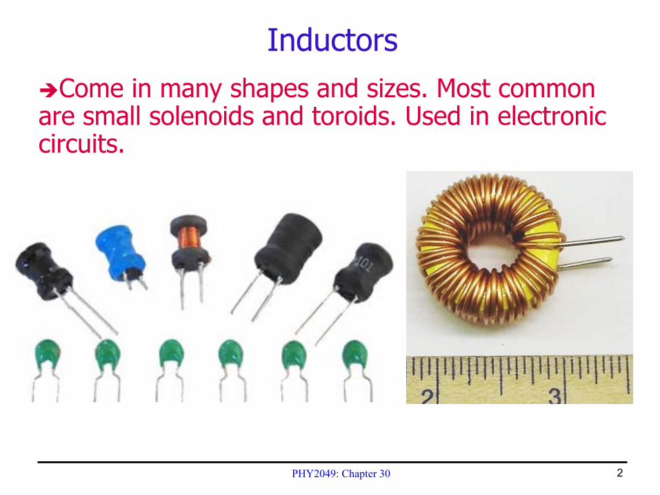
InductorsCome in many shapes and sizes. Most common
are small solenoids and toroids. Used in electronic circuits.
PHY2049: Chapter 30 3
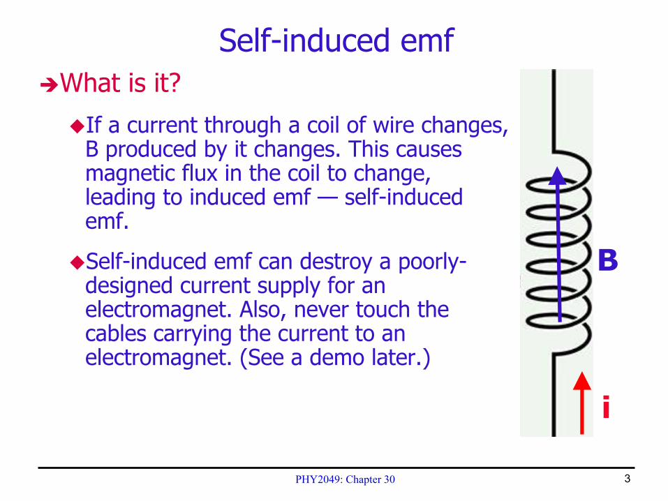
Self-induced emfWhat is it?
If a current through a coil of wire changes, B produced by it changes. This causes magnetic flux in the coil to change, leading to induced emf — self-induced emf.
Self-induced emf can destroy a poorly-designed current supply for an electromagnet. Also, never touch the cables carrying the current to an electromagnet. (See a demo later.)
i
B
PHY2049: Chapter 30 4
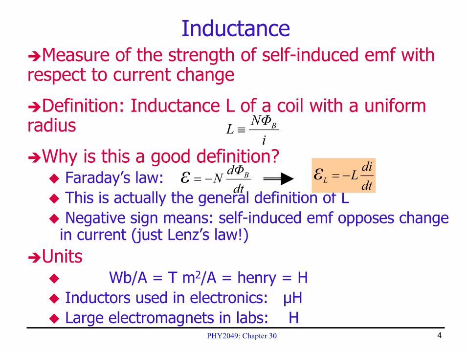
InductanceMeasure of the strength of self-induced emf with
respect to current change
Definition: Inductance L of a coil with a uniform radius
Why is this a good definition?Faraday’s law: This is actually the general definition of LNegative sign means: self-induced emf opposes change
in current (just Lenz’s law!)Units
Wb/A = T m2/A = henry = HInductors used in electronics: µHLarge electromagnets in labs: H
iΦNL B≡
dtΦdN Bε −= dt
diLLε −=
PHY2049: Chapter 30 5
CHECKPOINT 5
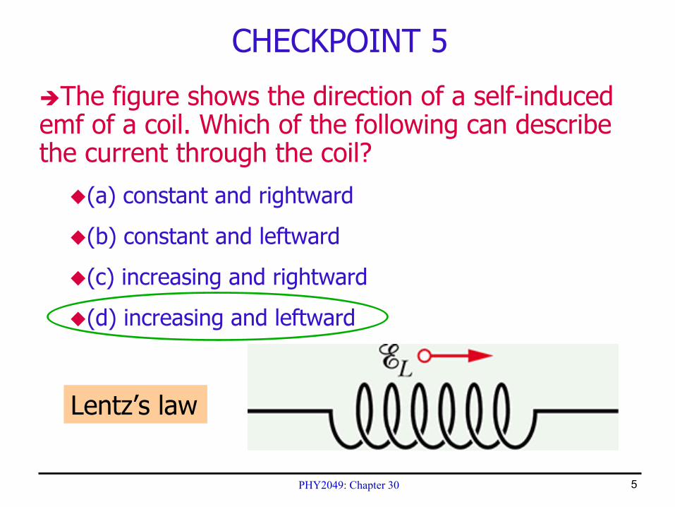
The figure shows the direction of a self-induced emf of a coil. Which of the following can describe the current through the coil?
(a) constant and rightward
(b) constant and leftward
(c) increasing and rightward
(d) increasing and leftward
Lentz’s law
PHY2049: Chapter 30 6
Example
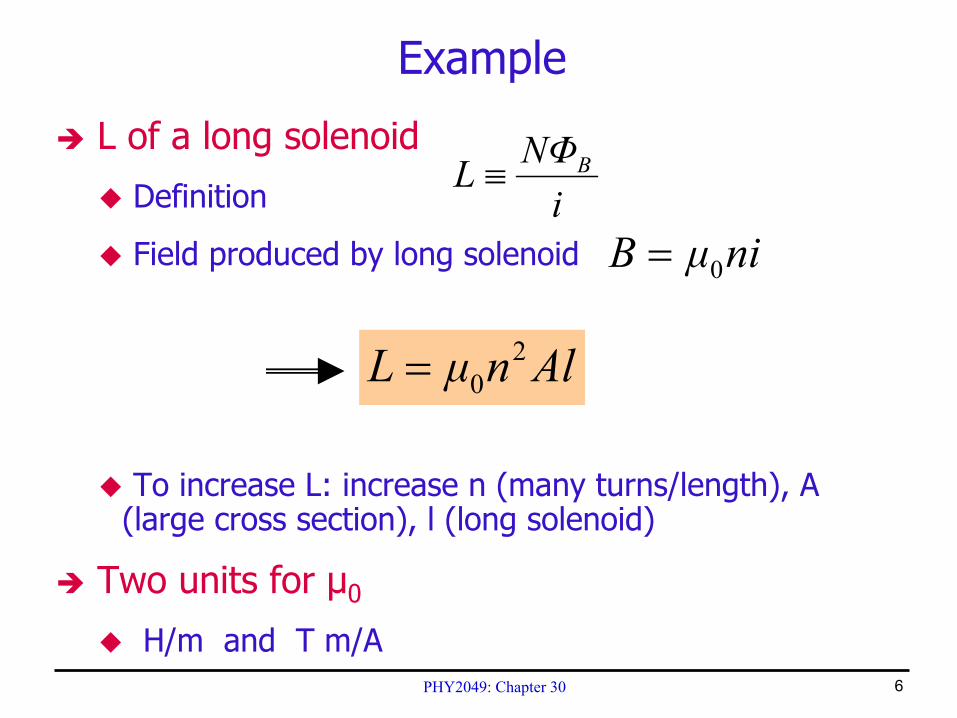
L of a long solenoid
Definition
Field produced by long solenoid
To increase L: increase n (many turns/length), A (large cross section), l (long solenoid)
Two units for µ0
H/m and T m/A
niµB 0=
AlnµL 20=
iΦNL B≡
PHY2049: Chapter 30 7
CHECKPOINT 6
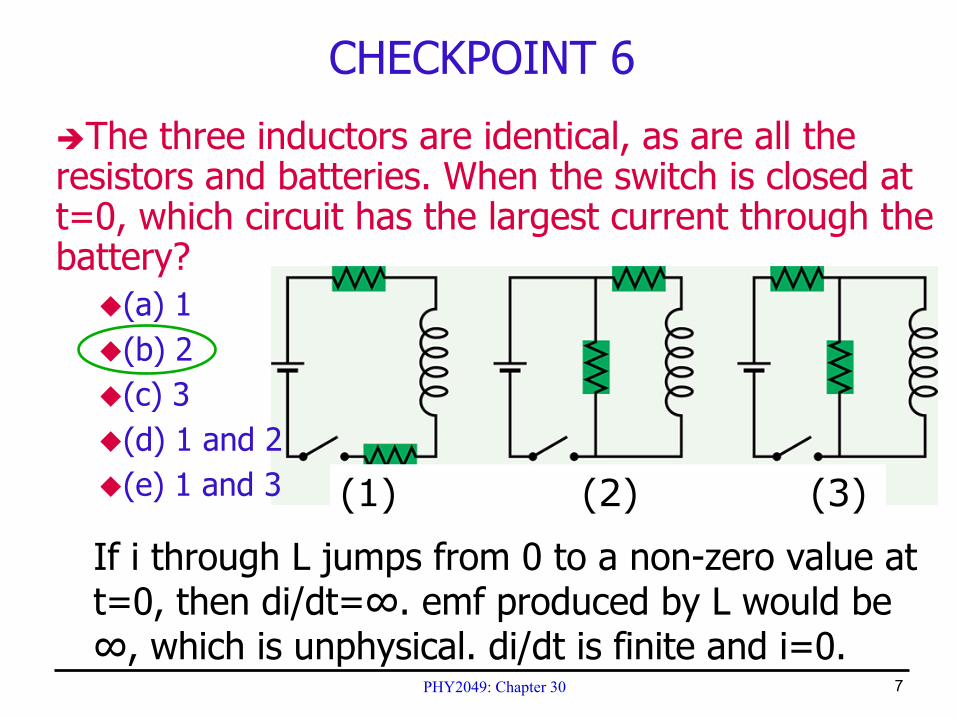
The three inductors are identical, as are all the resistors and batteries. When the switch is closed at t=0, which circuit has the largest current through the battery?
(a) 1(b) 2(c) 3(d) 1 and 2(e) 1 and 3 (1) (2) (3)
If i through L jumps from 0 to a non-zero value at t=0, then di/dt=∞. emf produced by L would be ∞, which is unphysical. di/dt is finite and i=0.
PHY2049: Chapter 30 8
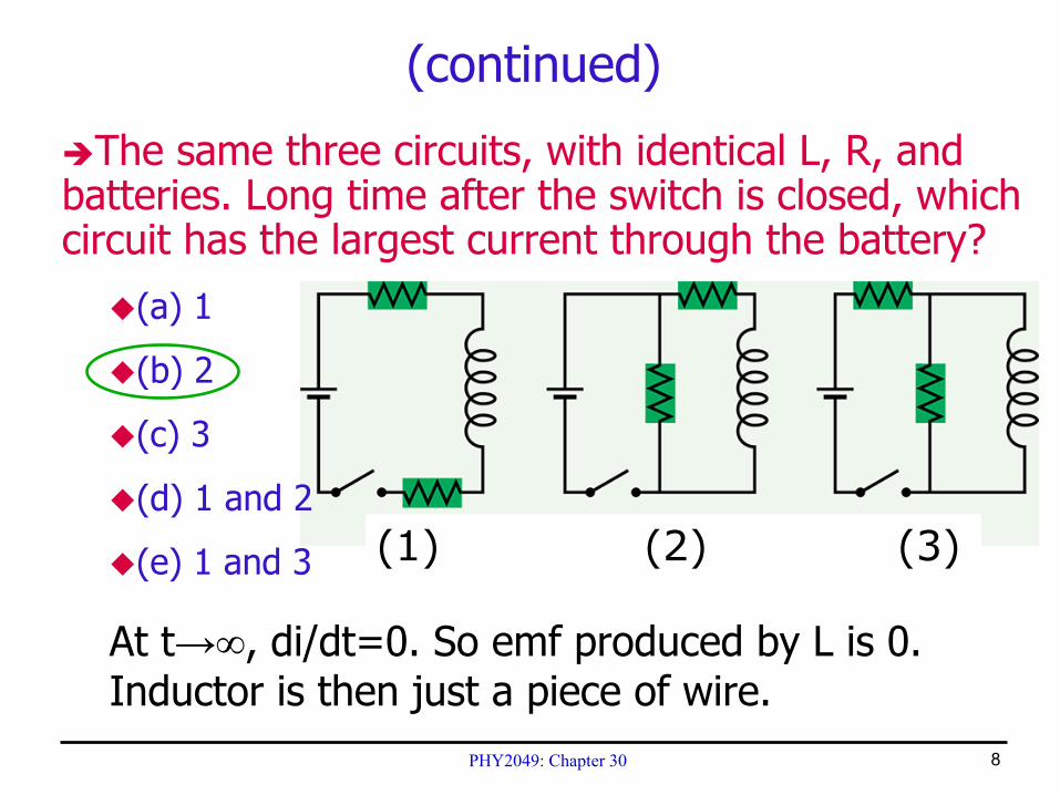
The same three circuits, with identical L, R, and batteries. Long time after the switch is closed, which circuit has the largest current through the battery?
(a) 1
(b) 2
(c) 3
(d) 1 and 2
(e) 1 and 3
(continued)
At t→∞, di/dt=0. So emf produced by L is 0. Inductor is then just a piece of wire.
(1) (2) (3)
PHY2049: Chapter 30 9
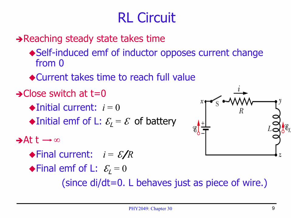
Reaching steady state takes timeSelf-induced emf of inductor opposes current change from 0Current takes time to reach full value
Close switch at t=0Initial current: i = 0Initial emf of L: ℇL = ℇ of battery
At t ∞Final current: i = ℇ/RFinal emf of L: ℇL = 0
(since di/dt=0. L behaves just as piece of wire.)
RL Circuit
PHY2049: Chapter 30 10
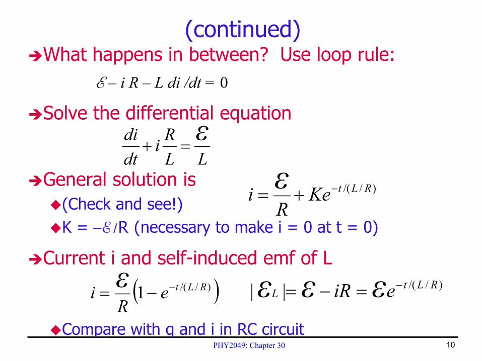
What happens in between? Use loop rule:E – i R – L di /dt = 0
Solve the differential equation
General solution is(Check and see!)K = −E /R (necessary to make i = 0 at t = 0)
Current i and self-induced emf of L
Compare with q and i in RC circuit
(continued)
LLRi
dtdi ε
=+
)//( RLtKeR
i ε −+=
)//(|| RLtL eiR εεε −=−=( ))//(1 RLte
Ri ε −−=
PHY2049: Chapter 30 11
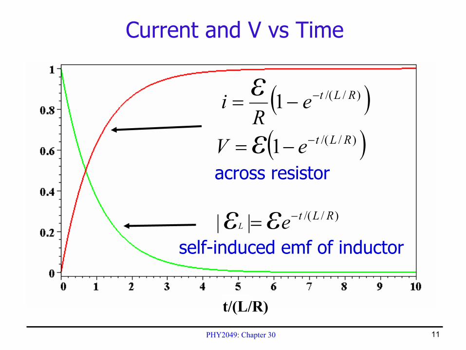
Current and V vs Time
( ))//(1 RLteR
i ε −−=
self-induced emf of inductor
)//(|| RLteεεL−=
t/(L/R)
( ))//(1 RLteV ε −−=across resistor
PHY2049: Chapter 30 12
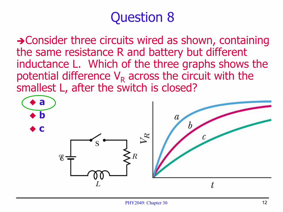
Question 8
Consider three circuits wired as shown, containing the same resistance R and battery but different inductance L. Which of the three graphs shows the potential difference VR across the circuit with the smallest L, after the switch is closed?
abc
PHY2049: Chapter 30 13
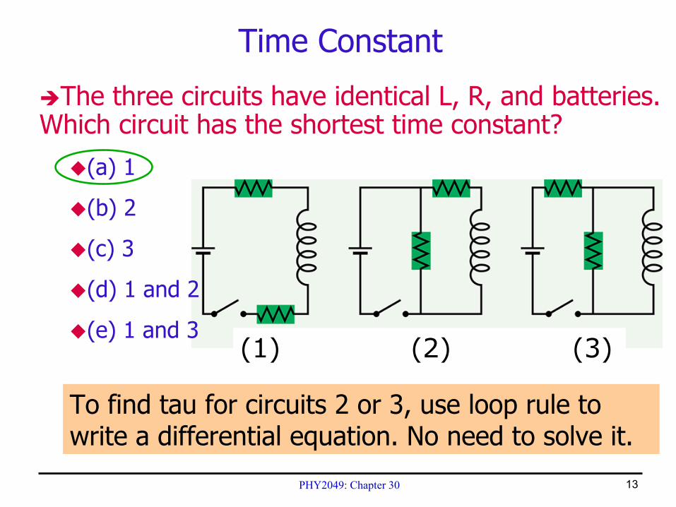
The three circuits have identical L, R, and batteries. Which circuit has the shortest time constant?
(a) 1
(b) 2
(c) 3
(d) 1 and 2
(e) 1 and 3
Time Constant
To find tau for circuits 2 or 3, use loop rule to write a differential equation. No need to solve it.
(1) (2) (3)
PHY2049: Chapter 30 14
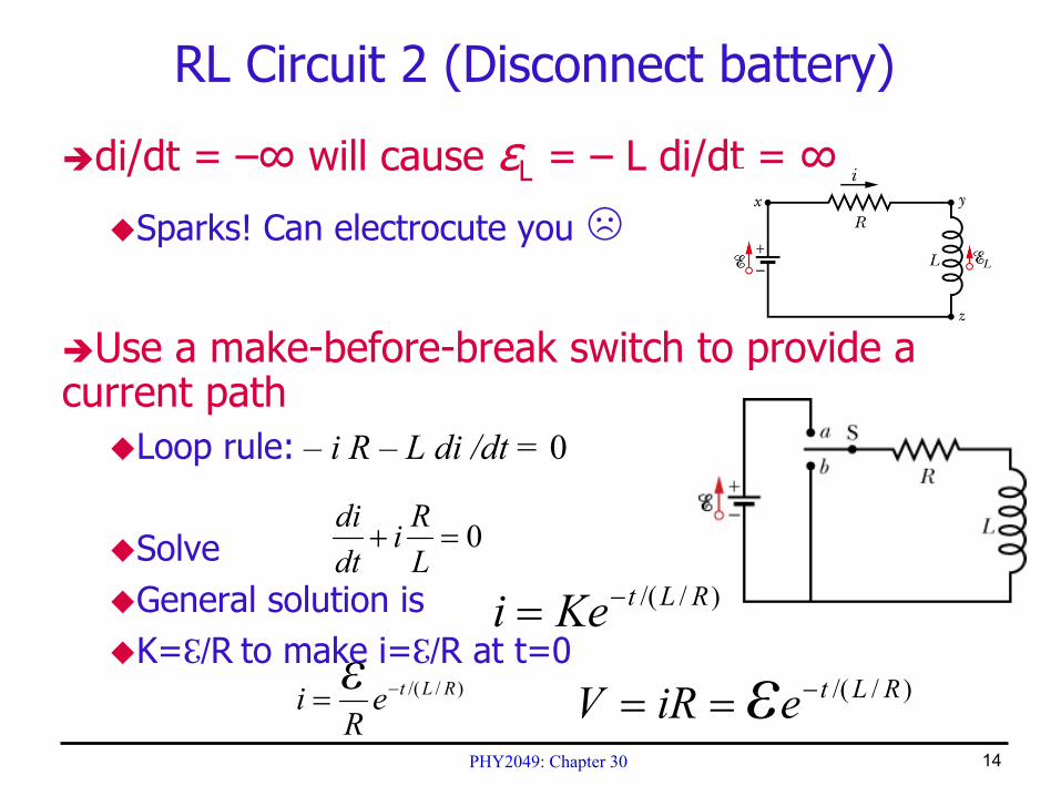
di/dt = –∞ will cause εL = – L di/dt = ∞
Sparks! Can electrocute you ☹
Use a make-before-break switch to provide a current path
Loop rule: – i R – L di /dt = 0
SolveGeneral solution isK=ℇ/R to make i=ℇ/R at t=0
RL Circuit 2 (Disconnect battery)
0=+LRi
dtdi
)//( RLtKei −=)//( RLte
Ri ε −= )//( RLteiRV ε −==
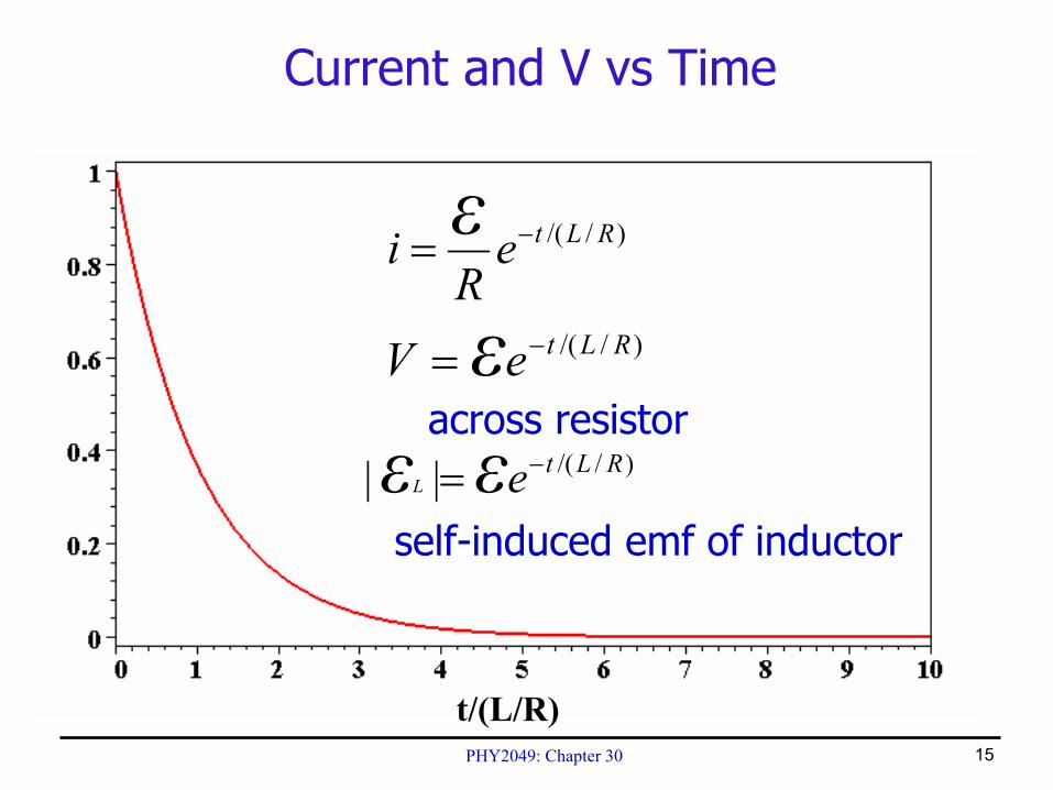
PHY2049: Chapter 30 15
Current and V vs Time
)//( RLteV ε −= ( ))//(1 RLteR
i ε −−=
)//( RLteV ε −=
)//( RLteV ε −=
)//( RLteR
i ε −=
across resistor
t/(L/R)
self-induced emf of inductor
)//(|| RLteεεL−=