2020 texas instruments electronics challenge: exploring
TRANSCRIPT

2020 Texas Instruments Electronics Challenge: Exploring Integrated Circuits
MAGS Roarbotix 2908E from Auckland, New Zealand
Matthew Batcheler (grade 11 equivalent)
Glory Bateman (grade 11 equivalent)
Max Davison (grade 10 equivalent)
Arnav Bhatiani (grade 10 equivalent)
Agam Aharon (grade 8 equivalent)
Evenly Yang (grade 11 equivalent)
Thanks to Mr Hinds for supervising us while using chemicals
(Report word count: 500)

Table of Contents Table of Contents .................................................................................................................................................2
Table of Figures ....................................................................................................................................................2
The report .............................................................................................................................................................3
Introduction ......................................................................................................................................................3
Disassembly ......................................................................................................................................................3
Analysis .............................................................................................................................................................3
Photographs .........................................................................................................................................................4
Parts List A – Main Integrated Circuit ................................................................................................................ 10
Part List B – Components on Die ....................................................................................................................... 11
Table of Figures Figure 1. The SN7404 IC prior to decapping. The “N” suffix indicates the package type, in this case plastic DIP
(Dual Inline Package) ............................................................................................................................................4
Figure 2. As much plastic as possible was removed with a Dremel tool, reducing the amount to be slowly
dissolved. Safety equipment was worn. ...............................................................................................................4
Figure 3. A water bath was prepared by heating a beaker. Acid and ICs were added to a tube inside the water
..............................................................................................................................................................................4
Figure 4. An early attempt. Note the red nitrogen dioxide fumes from the copper wires reacting with the
nitric acid. .............................................................................................................................................................5
Figure 5. Filtering the remains of the acid processing. The highly acidic black filtrate was neutralized with a
base before being disposed. .................................................................................................................................5
Figure 6. A photograph of the retrieved die mounted on its metal plate with a Chapstick for scale. .................6
Figure 7. The microscope and camera used to photograph the die. The following die photos were taken at
100x zoom ............................................................................................................................................................6
Figure 8. An image of the die. Note the gold bond wires over the white-looking copper traces. .......................7
Figure 9. The truth table describing the input and respective output for a single NOT gate ..............................7
Figure 10. A software (C++) implementation of a single NOT gate. The “!” operator inverts a value,
performing the operation .....................................................................................................................................7
Figure 11. Circuit diagram of each gate in the SN7404 hex inverter. Source: TI datasheet.................................7
Figure 12. Schematic of each gate in the related SN7405 open-collector hex inverter. Note 1 less transistor
on the output stage. Source: TI datasheet ...........................................................................................................7
Figure 13. An annotated die shot of the 7404. Note the 6 largely identical regions making each gate ..............8
Figure 14. A closeup of 1 gate. Transistors can be identified by a cluster of 3 nearby parallel wires – for base,
collector, and emitter. ..........................................................................................................................................8
Figure 15. Professional SN7405 die shot. This helped us to cross-reference with our die shot knowing
differences in circuit (fig.11, 12). Source: Project 5474 .......................................................................................9
Figure 16. Red overlay is SN7405 with 1 less transistor and diode than SN7404, helping us to estimate
components. D = diode, Q = transistor ................................................................................................................9
Figure 17. Pins of the die labelled. A = input, Y = output. Vcc marked in red, ground in black. Note Vcc passes
underneath at points. ........................................................................................................................................ 10

The report Introduction In 1958, Texas Instruments (TI) employee Jack Kilby invented the integrated circuit (IC)1 – a circuit compressed into a tiny package. ICs now make 80% of TI’s revenue2. Today, we often regard them as magic black boxes. However, the inner workings of these “chips” are fascinating and under-appreciated.
ICs are made of a tiny silicon and copper ‘die’ encased in plastic3. To make them, silicon is etched with microscopic electronic components by using photo-resistive chemicals and UV light4.
Disassembly We disassembled (‘decapped’) a TI SN7404 hex NOT gate to better understand how it worked. A NOT gate is a basic logic gate which outputs the inverse of its input (figure 9). We chose this IC because it was simple and available.
To remove the casing, we initially soaked the IC in nitric acid heated to 90˚C (194˚ F). This was not very effective and reacted with the copper producing toxic nitrogen dioxide fumes. Sulfuric acid of the same temperature worked better and slowly dissolved the casing, leaving the die. Hot acid is dangerous, so glasses were worn, a fume hood was used, and a chemistry teacher supervised us.
Analysis The die was approximately 1.5mm (about 0.06”) square and was mounted on a comparatively large piece of metal, aiding handling. It was transferred to a microscope equipped with a camera and photographed at 100x zoom. We believe that our images are primarily of the metal connective layer, rather than the silicon, as both our dissolving and microscopy was somewhat rudimentary.
The die has several gold bond wires attached, which connected it to the large wires leading out of the IC. Each of the 6 NOT gates have an input and output wire, and are connected to shared ground and power rails (a total of 14 pins). It made sense that there were 6 clear regions on the die – one for each gate.
Reverse-engineering the whole integrated circuit is difficult, however some components are relatively easy to identify, such as transistors. We were aided by a professional die shot of an SN7405 (a similar IC) and circuit diagrams from the SN7404 and SN7405 datasheets5 6. This helped us to understand the components we were looking at, allowing us to produce a bill of materials matched to the die.
A NOT gate can be made many ways. Software could be used, reducing the physical part count (figure 10), or discrete components could be utilized instead. This showed us how ICs aren’t magic – their internal components can be understood like any circuit.
1Laws, D. (2014). Who Invented the IC? - CHM. Computer History Museum. Retrieved 5 December 2020, from https://computerhistory.org/blog/who-invented-the-ic/. 2 Archived: About TI – Technology and innovation – TI.com. ti.com. (2016). Retrieved 5 December 2020, from https://web.archive.org/web/20160712074240/http://www.ti.com/corp/docs/company/technology_innovation.html. 3 JIMBLOM. Integrated Circuits - learn.sparkfun.com. sparkfun.com. Retrieved 5 December 2020, from https://learn.sparkfun.com/tutorials/integrated-circuits/all. 4 Woodford, C. (2020). Integrated circuits. explainthatstuff.com. Retrieved 5 December 2020, from https://www.explainthatstuff.com/integratedcircuits.html. 5 SN54,74(LS,S)04 Datasheet. Ti.com. (1983). Retrieved 5 December 2020, from https://www.ti.com/lit/ds/symlink/sn74ls04.pdf. 6 SN54,74(LS,S)05 Datasheet. Ti.com. (1983). Retrieved 5 December 2020, from https://www.ti.com/lit/ds/symlink/sn7405.pdf.

Photographs
Figure 1. The SN7404 IC prior to decapping. The “N” suffix indicates the package type, in this case plastic DIP (Dual Inline Package)
Figure 2. As much plastic as possible was removed with a Dremel tool, reducing the amount to be slowly dissolved. Safety equipment was worn.
Figure 3. A water bath was prepared by heating a beaker. Acid and ICs were added to a tube inside the water
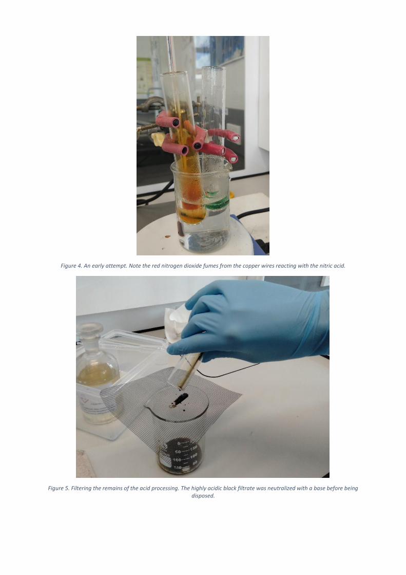
Figure 4. An early attempt. Note the red nitrogen dioxide fumes from the copper wires reacting with the nitric acid.
Figure 5. Filtering the remains of the acid processing. The highly acidic black filtrate was neutralized with a base before being disposed.
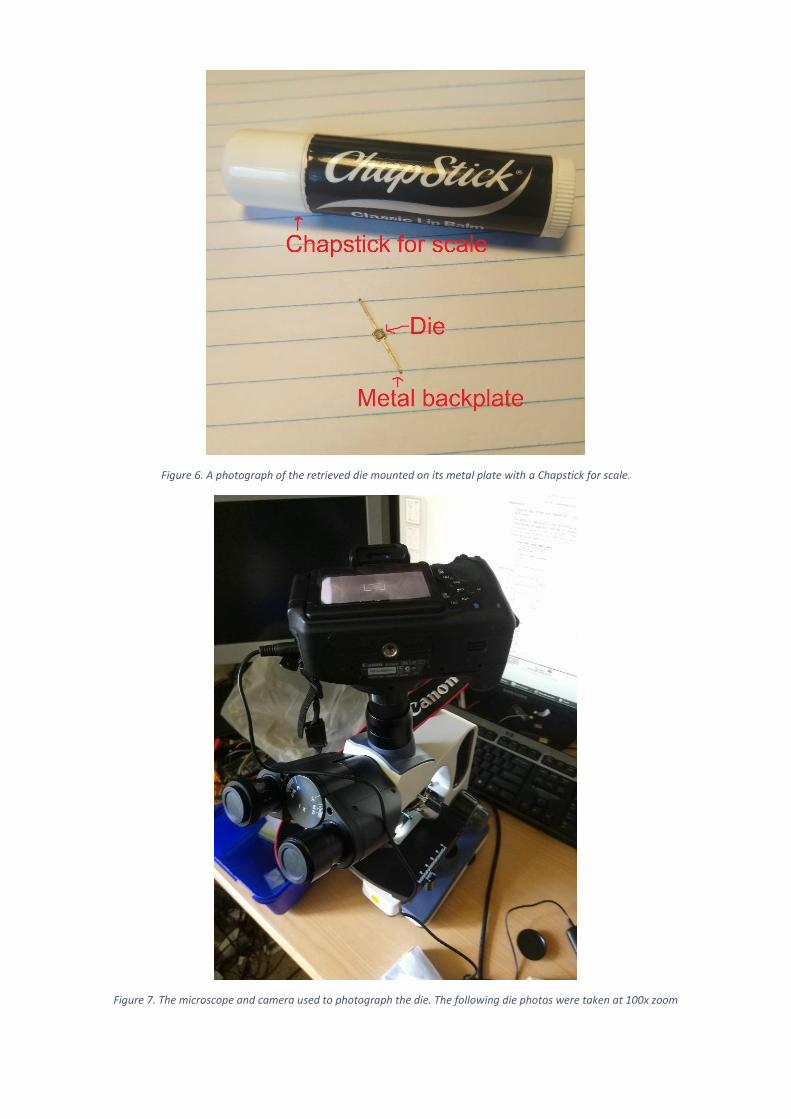
Figure 6. A photograph of the retrieved die mounted on its metal plate with a Chapstick for scale.
Figure 7. The microscope and camera used to photograph the die. The following die photos were taken at 100x zoom

Figure 8. An image of the die. Note the gold bond wires over the white-looking copper traces.
Figure 9. The truth table describing the input and respective output for a single NOT gate
Figure 10. A software (C++) implementation of a single NOT gate. The “!” operator inverts a value, performing the operation
Figure 11. Circuit diagram of each gate in the SN7404 hex inverter. Source: TI datasheet
Figure 12. Schematic of each gate in the related SN7405 open-collector hex inverter. Note 1 less transistor on the output stage. Source: TI datasheet
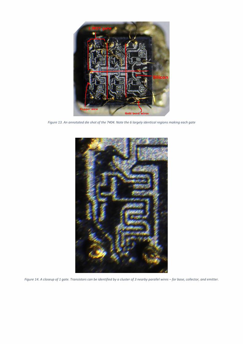
Figure 13. An annotated die shot of the 7404. Note the 6 largely identical regions making each gate
Figure 14. A closeup of 1 gate. Transistors can be identified by a cluster of 3 nearby parallel wires – for base, collector, and emitter.
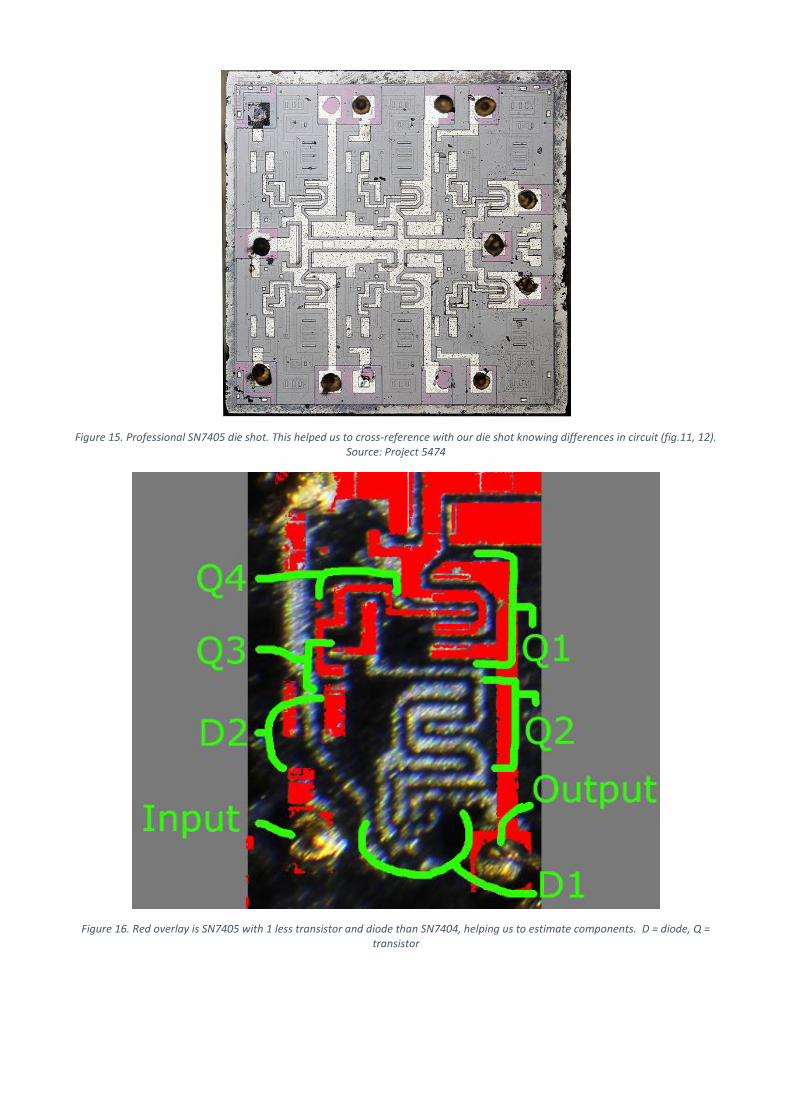
Figure 15. Professional SN7405 die shot. This helped us to cross-reference with our die shot knowing differences in circuit (fig.11, 12). Source: Project 5474
Figure 16. Red overlay is SN7405 with 1 less transistor and diode than SN7404, helping us to estimate components. D = diode, Q = transistor
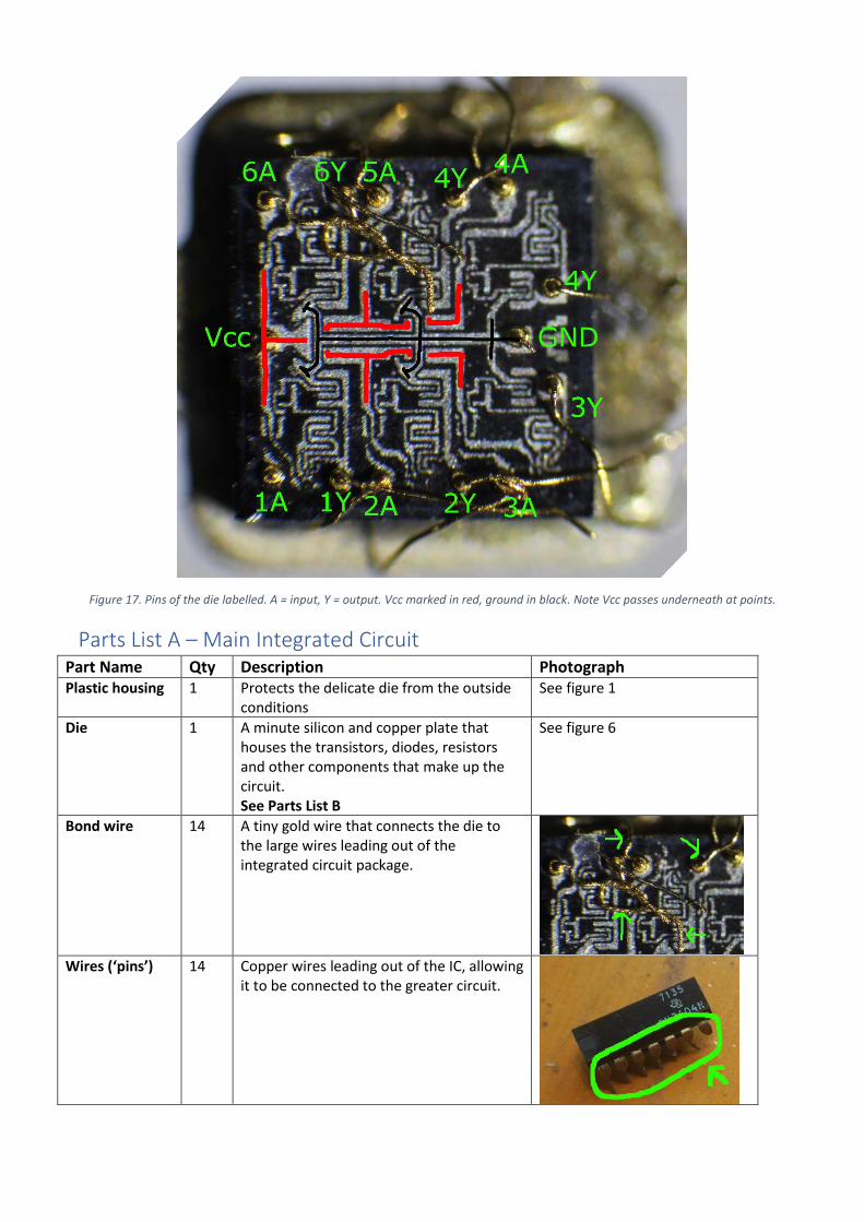
Figure 17. Pins of the die labelled. A = input, Y = output. Vcc marked in red, ground in black. Note Vcc passes underneath at points.
Parts List A – Main Integrated Circuit Part Name Qty Description Photograph Plastic housing 1 Protects the delicate die from the outside
conditions See figure 1
Die 1 A minute silicon and copper plate that houses the transistors, diodes, resistors and other components that make up the circuit. See Parts List B
See figure 6
Bond wire 14 A tiny gold wire that connects the die to the large wires leading out of the integrated circuit package.
Wires (‘pins’) 14 Copper wires leading out of the IC, allowing
it to be connected to the greater circuit.

Part List B – Components on Die Six NOT gates, each containing the following
Part Name
Qty Description IC photo Discrete component
Transistor (bipolar junction)
4 Can be used for many applications including a voltage or current-controlled switch or a voltage amplifier. Consists of 2 P-N type silicon junctions. In our photos, looks like 3 distinct wires nearby, which connect to each of the N, P, and N pieces of silicon making up the junction. Note most modern ICs use CMOS instead of bipolar junction transistors, so they look different. BJTs are simpler, so we chose an IC using them.
Diode 2 A component that only lets current flow one way. Consists of 1 P-N type silicon junction. In our photos, looks like 2 distinct nearby wires connecting to the P and N pieces of silicon.
Resistor 4 A component that restricts the amount of current able to flow.
Indistinguishable from a wire in our photos
Wire N/A Copper. Connects components together.