2019 zoneline air conditioner
TRANSCRIPT

2019 Zoneline Air Conditioner
31-9301 Rev. 1 ~ 7/1/2019
Technical Service Guide
230/208 VOLT MODELSAZ45E07D_ _ _5*AZ65H07D_ _ _5*AZ45E09D_ _ _5*AZ65H09D_ _ _5*AZ45E12D_ _ _5*AZ65H12D_ _ _5*AZ45E15D_ _ _5*AZ65H15D_ _ _5** Engineering Digit 5 and Greater
May 2019

– 2 –
GE Appliances, a Haier CompanyCopyright © 2019
All rights reserved. This service guide may not be reproduced in whole or in part in any form without written
permission from GE Appliances, a Haier Company.
For Warranty Information: 1. Go to http://products.geappliances.com2. Search the model number.3. Click on the Literature tab.4. Click on Use and Care Manual.5. Locate the Warranty page.
Warranty
Safety Information
IMPORTANT SAFETY NOTICE
The information in this service guide is intended for use by individuals possessing adequate backgrounds of electrical, electronic, and mechanical experience. Any attempt to repair a major appliance may result in personal injury and property damage. The manufacturer or seller cannot be responsible for the interpretation of this information, nor can it assume any liability in
connection with its use.
WARNING
To avoid personal injury, disconnect power before servicing this product. If electrical power is required for diagnosis or test purposes, disconnect the power immediately after performing the
necessary checks.
RECONNECT ALL GROUNDING DEVICES
If grounding wires, screws, straps, clips, nuts, or washers used to complete a path to ground are removed for service, they must be
returned to their original position and properly fastened.

– 3 –(Continued next page)
Table of Contents
Safety Information ........................................................................................................................2
Warranty .......................................................................................................................................2
Table of Contents ..........................................................................................................................3
Safety Requirements ....................................................................................................................6
Tools Required ..............................................................................................................................7
Caution .................................................................................................................................7
Nomenclature ...............................................................................................................................8
Operation ......................................................................................................................................9
Cooling .................................................................................................................................9
Heating .................................................................................................................................9
Heat Pump Operation ...........................................................................................................10
All Heat Pump Lockout Mode ...............................................................................................12
Boost Heat Mode ..................................................................................................................12
Fan Cycle Operation .............................................................................................................13
Fan Cycle - Resistance Heating Mode .................................................................................14
Fan Cycle - Heat Pump Mode ..............................................................................................15
Constant Fan ........................................................................................................................16
Random Restart ...................................................................................................................17
Freeze Prevention for Indoor Coil (Cooling) .........................................................................19
Indoor Coil Overheat Protection ...........................................................................................20
Reverse Cycle Defrosting Heat Pump Mode ........................................................................21
Internal Condensate Removal Control .................................................................................22
Heat Sentinel Mode ..............................................................................................................23
Freeze Sentinel Mode ..........................................................................................................23
Control Lockout ....................................................................................................................23
Auxiliary Controls ..................................................................................................................23
Auxiliary Set Button ..............................................................................................................24
CDC: (Field Supplied) ...........................................................................................................25
External Fan: (Field Installed) ...............................................................................................25
Remote Thermostat ..............................................................................................................25

– 4 –
Thermistors ...................................................................................................................................26
Thermistors ...........................................................................................................................26
Thermistors Indoor................................................................................................................26
Thermistors Outdoor .............................................................................................................26
Controls ........................................................................................................................................27
Main Board: Front Cover ......................................................................................................27
Power Cords .........................................................................................................................28
Main Board - Front ................................................................................................................29
RJ-45 ....................................................................................................................................29
Main Board ...........................................................................................................................30
Component Checks at Main Board .......................................................................................31
Fault Codes ..................................................................................................................................32
Service Mode ...............................................................................................................................34
Accessing Controls ...............................................................................................................35
Low Voltage Transformer ......................................................................................................36
Service Main Board ......................................................................................................................37
User Interface ...............................................................................................................................39
Air System ....................................................................................................................................40
Fan Motors ...........................................................................................................................40
Indoor Fan Motor ..................................................................................................................40
Indoor Blower Wheel ............................................................................................................40
Indoor Fan Bearing ...............................................................................................................41
Outdoor Fan Motor Shroud ...................................................................................................42
Outdoor Fan Motor ...............................................................................................................43
Electric Heat .................................................................................................................................44
Heater ...................................................................................................................................44
Condensate Removal ...................................................................................................................46
ICR System ..........................................................................................................................46
ICR Pump .............................................................................................................................46
Slinger on Outdoor Fan Blade ..............................................................................................46
Damper Door ........................................................................................................................47
Make-Up Air Module (MUAM) ...............................................................................................47
(Continued next page)

– 5 –
Sealed System .............................................................................................................................50
Compressor ..........................................................................................................................51
Reversing Valve ....................................................................................................................51
Service Replacement Valve Assembly .................................................................................52
Sealed System: Refrigerant Flow Cooling ....................................................................................53
Sealed System: Refrigerant Flow Heating ...................................................................................54
Recovery Process ........................................................................................................................55
Charging Summary ......................................................................................................................56
Refrigerant Charge ...............................................................................................................56
Schematic/Wiring Diagram ...........................................................................................................57
New Accessories ..........................................................................................................................58
Index .............................................................................................................................................59

– 6 –
Prior to disassembly of the Zoneline to access components, GE Factory Service technicians are REQUIRED to follow the Lockout /
Tagout (LOTO) 6 Step Process:
Safety Requirements
GE Factory Service Employees are required to use safety glasses with side shields, safety gloves andsteel toe shoes for all repairs.
Step 1Plan and Prepare
Step 4Apply LOTO device and lock
Step 2Shut down the appliance
Step 5Control (discharge) stored energy
Step 3Isolate the appliance
Step 6“Try It” verify that the appliance islocked out
Steel Toed Work Boot
Electrically Rated Glove and Dyneema® Cut Resistant Glove Keeper
Dyneema®Cut Resistant Glove
Cut Resistant Sleeve(s)
Plano Type Safety Glasses
Brazing Glasses Prescription Safety Glasses
Safety Glasses must be ANSI Z87.1-2003 compliant

– 7 –
System Pressures
Technicians with R-22 experience will need to become familiar working with high and low side pressures that are much higher when using R-410A. A typical R-22 system operates normally with a high side pressure of approximately 260 psi @ 120°F condensing temperature and a low side pressure of approximately76 psi @ 45°F evaporator saturation temperature.
A normally operating R-410A system with the same condensing temperature of 120°F and 45°F evaporator saturation temperature will have a high side pressure of approximately 500 psi and a low side pressure of approximately 150 psi.
• 5/16-in. socket or drive
• 1/4-in. socket or drive: Ground screws and control assembly use 1/4-in. machine thread screws
• 3/8-in. socket or drive: For outdoor fan blade removal
• 4-mm Allen wrench: For indoor fan blade removal
• Volt Ohm Meter
• Amp probe
• Needlepoint meter leads
• Sealed system and R-410A recovery equipment
• Thermal paste (Part #: WX5X8927)
• Extension needed for condenser shroud screws
Tools Required
Caution

– 8 –
Nomenclature
The nomenclature breaks down and explains what the letters and numbers mean in the model number.
Serial NumberThe first two characters of the serial number identify the month and year of manufacture. The letter designating the year repeats every 12 years.
Example: LA123456S = June, 2013
A – JAND – FEBF – MARG – APRH – MAYL – JUNM – JULR – AUGS – SEPT – OCTV – NOVZ – DEC
2024 – Z2023 – V2022 – T2021 – S2020 – R2019 – M2018 – L2017 – H2016 – G2015 – F2014 – D2013 – A
Model Number
A Z 4 5 E 0 9 D A B W 5
ZonelinePackage Terminal Chassis
Chassis Series45: Deluxe Electric Heat Electronic Control65: Deluxe Heat Pump Electronic Control
Unit TypeE: Cooling with Electric Resistance HeatH: Heat Pump with Electric Resistance Heat Universal Power Connection
A: These models use power cord kits; heater size determined by a power cord kit.B: These models use power cord kits; heater size determined by a power cord kit and have MUAM (Make Up Air Module)
Special Features: B: Base UnitC: Corrosion TreatedD: Internal Condensate Removal (ICR) System (Heat Pump Only)P: Heat Pipe, Dry 25M: Make Up Air Module
Engineering Revision
Compressor TypeM: MBW: Rechi
Voltage/FrequencyD: 230/208 Volt 60 Hz Single PhaseE: 265 Volt 60 Hz Single Phase
Nominal Cooling Capacity07: 7,000 BTU/hr.09: 9,000 BTU/hr.12: 12,000 BTU/hr.15: 15,000 BTU/hr.
Mini Manual Location (Bottom of Pan)Model Serial Location

– 9 –
For both AZ4500 and AZ6500, once the compressor comes on in cooling, it will pull the room temperature down to the thermostat setting.
Fan pulsing for temperature checking after compressor shut-off, when not in Class 2 mode:
• The Zoneline will pulse the indoor fan periodically when it is not on a remote thermostat and set to cycle cooling.
• The system will wait 6 minutes after the compressor shuts off, then pulse the indoor fan, pulling air across the air sensor for a duration of 30 seconds.
• Should the first 2 minute pulse not activate the Zoneline, the system will continue pulsing until cooling is needed.
• Each pulse of the fan is running at low speed, no matter what setting the user has chosen.
Operation
Cooling
AZ4500 In the cooling mode, the compressor, indoor fan and outdoor fan run.
AZ6500 In the cooling mode, the compressor, indoor fan and outdoor fan run, the reversing valve is energized throughout the entire cooling cycle.
Heating
AZ4500 In the heating mode, AZ4500 will utilize the built-in resistance heater, running with the indoor fan at one of two speeds determined by the Fan Speed selection.
Resistance heater output is not determined by software. It is determined by hardware (power cord amperage rating).
Temperature control in the heating mode is done by cycling the resistance heater under control of the room air sensor, or the room thermostat (if in Class 2 Mode).
Whenever the room temperature is 1.8°F below the temperature setting, the control will energize the heating cycle and remain in operation until the room temperature reaches the temperature setting. At this point, the Zoneline will turn off the heating cycle.
Room Temp Setpoint 1.8°F
Room Temp
ON ON
Room Temp Setpoint
Room Temp Setpoint
1.8°F
ON ONHeating
Mode

– 10 –
When an AZ6500 Zoneline is in the heating mode, the resistance heater or the compressor runs with the appropriate fans. The control is capable of independently switching power for two resistance heater loads. Each of the two heater loads can be made up of different heating elements, but the elements will be tied together in parallel. There are three stages of operation associated with the heating mode:
• Stage 1: Heating due to heat pump (compressor) with both fans on.
• Stage 2: Heating due to heat pump (compressor) and supplemental 1,000-watt resistance heater (Heater A) with both fans on. (this mode can also be activated via the Auxiliary Set (or Aux Set) mode to run in place of stage 1 heating). This auxiliary setting is known as Boost Heat, and essentially disables Stage 1 heating which is replaced by Stage 2 heating. When this mode is active, it will run when the Zoneline is being controlled via the Zoneline control panel or when a remote wall thermostat is connected and calling for heat pump. It will override Stage 1 heating in both cases. NOTE: Any time the Zoneline enters Stage 2 heating mode, it should continue heating in this mode until the room temperature is satisfied. If the room offset increases, then Stage 3 heating will be engaged.
• Stage 3: Heating due to resistance heater (Heater A, B and C); indoor fan only on.
NOTE: Any time the Zoneline enters Stage 3 heating mode, it will continue heating in this mode until the room temperature is satisfied, regardless of indoor room temperature offset or outdoor temperature conditions. The Zoneline can then resume normal heating operation modes of Stage 1 or Stage 2 heating upon the next call for heat.
NOTE: In low fan speed, the Zoneline will only activate heater A and B to allow for a maximum heater output of 3,800 watts. A, B, and C output is only available in high speed. Heat Pump Mode and Heater B will never be on at the same time.
Upon initial start-up or resumption after a power interruption, Stage 3 (Heater A and Heater B) are energized at full power to generate heat until the room temperature rises to the temperature setting regardless of the outdoor temperature.
Automatic changeover between the compressor and the heating elements is utilized.
In order to keep the compressor from stalling out when trying to start against the high side refrigerant pressure, the control circuit has a built-in automatic time delay to allow the internal pressure to equalize. The control circuit will not try to start the compressor until it has been off for 3 minutes. To minimize compressor cycling, the control has a built-in minimum compressor run time of 3 minutes (+/- 10 seconds). Even if the thermostat is satisfied, or the indoor temperature is dropping, the compressor will run for a minimum of 3 minutes. The Zoneline can switch to Stage 2 heating, but must wait until the 3 minutes of compressor run time is satisfied before switching to Stage 3 heating.
• FIRST STAGE HEAT (HEAT PUMP ONLY)
Once heating initializes, the room temperature will start to rise. The compressor will run until the temperature rises 0.9°F above the temperature control setpoint, at which time the compressor will shut down. If the outdoor ambient temperature is less than 25°F, Stage 1 heating will be disabled and only Stage 3 heating will energize. This is also the case for the remote wall thermostat. When the outdoor ambient temperature is greater than 46°F, the Zoneline runs at First Stage (Heat Pump).
• SECOND STAGE HEAT (HEAT PUMP + HEAT A): Boost Heat mode
When either the room temperature falls from the setting by greater than 1.8°F, or the outdoor temperature is lower than 25°F, Stage 2 heating will be disabled and only Stage 3 heating will energize.
If the outdoor temperature is above 25°F the control will energize Stage 2 heating. Stage 2 heating will continue to operate until the room temperature exceeds the temperature control setpoint by 0.9°F, at which time the heater and compressor will stop.
Heat Pump Operation

– 11 –
NOTE: The second stage heat is not utilized in Class 2 mode. Unless the Auxiliary Set (or Aux Set) "boost heat" is selected. Stage 2 heating will operate when the thermostat calls for Stage 1 heating.
• THIRD STAGE HEAT (HEATERS A AND B ONLY)
When the room temperature falls below 2.7°F from the temperature control setpoint, the heat pump operation will stop. Stage 3 heating is activated (based on power cord) for all outdoor temperatures, except for l2R lockout conditions. Stage 3 will continue to operate until the room temperature exceeds the temperature control setpoint by 0.9°F at which time the heaters will shut down.
Stage Heating Mode Logic for AZ6500 Series
Temp. Setting +0.9°F
Heater B
Heater A
Compressor
Temp. Setting -2.7°F
Temp. Setting -1.8°F
Room Temp.
Temp. Setting
ON
ON
ON
ON
ON

– 12 –
All Heat Pump Lockout Mode
AZ6500 Series ONLY.
The Heat Pump Lockout is controlled through the Auxiliary Set mode. When this Auxiliary Set button is on, the control will run in electric resistance heat (Stage 3) mode only, with the heat pump operation (Stage 1 and 2 heating) off. When the Auxiliary Set button mode is off, the heat pump is allowed.
The heat pump lockout mode is utilized in the Class 2 mode.
NOTE: If the Heat Pump Lockout mode and Boost Heat mode are both selected as active in the auxiliary settings, the Heat Pump Lockout mode takes priority, and Heat Pump modes remain off.
Boost Heat Mode
AZ6500 Series ONLY.
When the Boost Heat Auxiliary Set button is enabled and the outdoor temperature is above 25°F, the first stage heat (heat pump only) is locked out.
It will be controlled through an Auxiliary Set Button mode. Staged Heating selection logic and Resistance Heat Lockout mode have priority over this function.
This Boost Heat setting is used to provide supplementary heat to the heat pump operation in conditions where the heat pump only operation (Stage 1 heat) is not sufficient to maintain a consistent comfortable room temperature for the consumer.
Fan Only Mode: All models
In the Fan Only mode, the indoor fan runs continuously at the fan speed selected (High or Low). All other loads are de-energized.

– 13 –
Fan Cycle Operation
There are two Fan Cycle auxiliary settings. These modes are utilized to switch between CONTINUOUS setting, the fan motor continues to operate even when the compressor or the electric heater cycles ON/OFF. In the CYCLE setting, the indoor fan cycles ON/OFF with the heating and cooling functions.
When the Class 2 mode is selected, the fan motor is controlled by the remote wall thermostat, independent of positions of Fan Cycle auxiliary set button modes.
Fan Cycle: Cooling Mode
The indoor fan runs for a short period of time, approximately 3 seconds, before the compressor and outdoor fan are turned on.
The indoor fan runs continuously for a short period of time, approximately 30 seconds, after the compressor and outdoor fan are turned OFF.
In the cooling mode, the indoor fan is designed to operate at two different speeds. If the control happens to be in the compressor restart delay (allowing the internal pressure to equalize before turning the compressor ON), the indoor fan turns ON in the normal sequence as shown in the figure. The outdoor fan and compressor turn ON at the end of the restart delay.
In the Class 2 mode, the indoor fan will be controlled directly by the remote thermostat.
FAN CYCLE: COOLING MODE
Temperature
Setting +1.8°F
COMPRESSOR AND OUTDOOR
FAN
INDOOR FAN
Temperature
ON ON
ON ON
6 sec 3 sec

– 14 –
The indoor fan and heaters are turned ON at the same time. The indoor fan is turned OFF, approximately 20 seconds after the heaters are de-energized as shown. In the OFF mode, the indoor fan will continue to operate for 6 seconds after the user has stopped the Zoneline, in order to dissipate the heat inside the Zoneline.
In the heating mode, the indoor fan is designed to operate at two different speeds (RPM).
FAN CYCLE: RESISTANCE HEATING MODE
Fan Cycle - Resistance Heating Mode
Temperature
Temperature Setting -1.8°F
Heater
INDOOR FAN
ON
20 sec
ON
ON

– 15 –
AZ6500 series ONLY.
The indoor fan is turned on 3 seconds before the compressor and outdoor fan is turned ON. The outdoor fan and the compressor are turned ON at the same time. The indoor fan is then turned OFF 6 seconds after the compressor and outdoor fan are turned OFF.
FAN CYCLE: HEAT PUMP MODE
Fan Cycle - Heat Pump Mode
Temp. Setting +0.9°F
Temperature
COMPRESSOR AND OUTDOOR FAN
INDOOR FAN
ON
ON ON
ON
6 sec
3 sec

– 16 –
Constant Fan
In Constant Fan mode, the Zoneline operates in High Fan mode regardless of fan setting.
This feature allows the fan to operate even when the Zoneline is set in the OFF position. This will allow continuous air circulation in the room even if the Zoneline is turned off. This function is available as a selectable option through the use of an Auxiliary Set button mode. The selection of this function will override the CDC provision.
Fan Operation
Both fan motors are variable speed DC fan motors with RPM feedback and regulation control. Any time a fan is energized, the control checks that the fan reaches the target RPM speed +/- 150 RPMs. If the target cannot be met, the fan motor will shut down for 15 minutes, and will set a fault code. It will reattempt to run every 15 minutes. If the fan motor reaches the proper RPM, the fault code will clear. If the fault does not clear, the fault code will be stored in memory and the Zoneline will function as follows:
• For detected indoor fan failures, the Zoneline will cease all operation until the next try to energize the fan.
• For detected outdoor fan failures, the Zoneline will revert to Stage 3 heating if it is trying to run in Stage 1 or Stage 2 heating. The Zoneline will then run the indoor fan only if it is trying to run in Cooling Mode.

– 17 –
The start-up condition for the different modes is shown in the following two diagrams. This function allows for the random restart of Zonelines in a building in the event of a power outage. The restart delay will reduce the initial inrush current from the building to help prevent a second power outage of indefinite length. The controls will revert to settings established prior to the outage.
The Random Restart function is effective in the Class 2 mode.
Random Restart for AZ4500 Series
Random Restart
Cool Mode
Heat Mode
Stop Mode
Compressor RunPower Down
Power Down
3 mins.
Power Recovered
Range
StopFan Operation
Electric Heat Operation
Power Recovered
Compressor Run
Fan Operation
Electric Heat Operation
Range
Power Recovered
StopStopStop
(Continued next page)

– 18 –
Random Restart for AZ6500 Series
The main board will power up the Zoneline randomly over a 3 to 20 seconds timing period.
Cool Mode
Heat Mode
Stop Mode
Compressor Run
Power Down
Heat Pump Operation
3 mins.
Power Recovered
Range
StopFan Operation
Quick Heat Recovery
Compressor Run
Power Down
Power Down
Power Recovered
Power Recovered
Stop
Stop Stop Stop
Range
Fan Operation

– 19 –
Freeze Prevention for Indoor Coil (Cooling)
Cooling Mode
During the cooling operation, if the temperature of the indoor coil falls below 34°F for a period of approximately 5 minutes, the compressor will shut off. This will prevent the indoor coil from freezing. The compressor will start running again when the coil temperature reaches 50°F or above.
However, the safety restarting function will prevent the compressor restarting if the minimum 3 minute shutdown time period has not elapsed. The indoor fan motor will continuously operate during this coil freezing prevention mode.
The indoor coil freeze prevention function is also available in the Class 2 mode.
Freeze Prevention for Indoor
Indoor Coil Temperature
Compressor
Indoor Fan
Outdoor ON ON
ON
ONON
50°F
34°F
5 min
5 min

– 20 –
Heat Pump Operation
The Overheat Protection is only on the AZ6500 series.
The Overheat Protection system protects the Zoneline from overworking when the outdoor temperature is too high for heat pump operation. The temperature of the indoor coil is monitored, and if it rises above 131°F, the control stops the outdoor fan. The Zoneline will resume normal operation when the coil temperature is below 122°F.
Indoor Coil Overheat Protection
Indoor Coil Overheat Protection
Indoor Coil Temperature
131°F
122°F
Outdoor Fan
Compressor
ON
ON

– 21 –
Reverse Cycle Defrosting Heat Pump Mode
Reverse Cycle Defrost shall be controlled as a function of compressor run time and outdoor coil temperature.
a) Defrost Enable
The reverse cycle defrost shall begin when either:
1. The outdoor coil temperature, as measured by the S4 thermistor during compressor operation is less than or equal to 14°F for at least 3 consecutive minutes.
-OR-
2. The outdoor temperature as measured by the S3 Thermistor, is less than or equal to 42°F OR the outdoor coil temperature is less than or equal to 32°F for at least 3 hours of accumulated compressor run time.
NOTE: As described at step 1, if the outdoor coil temperature, as measured by the S4 thermistor, rises above 14°F before 3 minutes has elapsed; the accumulated time register is reset to zero. A defrost sequence will not be initiated, as a result.
NOTE: As described in step 2, if the outdoor temperature, as measured by the S3 thermistor, rises above 42°F AND the outdoor coil temperature as measured by the S4 thermistor, rises above 42°F before 3 hours of compressor run time has been accumulated; the accumulated time register is reset to zero. A defrost sequence will not be initiated, as a result.
b) Defrost Operating Sequence
When either of these conditions are detected, the Zoneline will initiate a reverse cycle defrost. The following steps comprise the reverse cycle defrost:
1. Immediately stop heat pump operation.
2. Run stage 3 heating until room temperature is satisfied.
3. Wait for compressor off time (3 minutes) to be satisfied.
4. Run reverse cycle defrost (cooling mode without fans) until either:
• the outdoor coil temperature rises to 68°F
• or the total elapsed time of compressor run in reverse cycle defrost reaches 9 minutes
5. Run a stage 3 heating cycle to satisfy room temperature.
6. If reverse cycle defrost is exited due to
• the outdoor coil rising above 68°F, resume normal heat pump operation
• the total elapsed time exceeding 9 minutes and total number of defrost cycles is less than 5, go back to step 4 and run another defrost cycle. If the total number of defrost cycles equals 5, see Abnormal Defrost Fault below
c) Abnormal Defrost Fault
If five consecutive defrost cycles have been completed and the outdoor coil has not reached 68°F, an Abnormal Defrost Fault will be initiated. Heat Pump operation is disabled while this fault is active. The Zoneline will wait for the following conditions to be met.
1. Elapsed time > 4.5 days
and
2. Outdoor Coil Thermistor > 42°F
and
3. Outdoor Ambient > 42°F
At this time, up to five more defrosts will be attempted. If the outdoor coil thermistor stays below 68°F, it will reenter abnormal defrost fault. If it increases above 68°F, it will resume normal heat pump operation.
Reverse cycle defrost has the highest priority. Once the defrost starts the defrost operation continues regardless of any temperature conditions and any kind of manual operation, except for changing the operation switch.
Reverse cycle defrost is used in Class 2 mode. During reverse cycle defrost, all Class 2 signal modes are overridden except when "Cooling" is called from the thermostat.

– 22 –
Internal Condensate Removal Control
Internal Condensate Removal Control (AZ6500 Only)
The Internal Condensate Removal (ICR) function will be utilized to drip the condensation, from the base pan, onto the indoor coil to evaporate it when the compressor is running during the heat pump operation.
During heat pump operation, the ICR system will pump condensate water from the Zoneline base pan into a collector tray positioned above the indoor coil.
That condensate will then drain from the tray onto the warm indoor coil where it will be evaporated into the room atmosphere. If an excessive amount of condensate water is pumped to the indoor side, the excess amount will be routed back to the outdoor portion of the base pan.
The ICR function will be in tandem with heat pump compressor operation except in case of Reverse Cycle Defrosting.
The ICR function will be utilized in the Class 2 mode.
ICR Pump Operation
33°F
28°F
ICR Pump
3 min.
OnOn
Outdoor Air Temp.

– 23 –
To prevent the room from overheating (Zoneline must be powered), cooling is energized when the indoor temperature is sensed to be 85°F to maintain room temperature below 85°F in any operation mode except heating mode. The Heat Sentinel mode is disabled when the room temperature reaches 80°F. The indoor fan runs at high speed. An auxiliary set mode is provided to enable the heat sentinel. If the auxiliary mode is in the OFF position, the heat sentinel function is disabled. The factory default of the mode is OFF.
To prevent the room from freezing, the electric heater is energized to maintain the room temperature above 41°F regardless of any operation mode.
The freeze sentinel mode is disabled when the room temperature reaches 46°F.
The indoor fan runs at high speed. An auxiliary set mode is provided to enable the freeze sentinel. If the auxiliary mode is in the OFF position, the freeze sentinel function is disabled. The factory default of the mode is ON.
The control panel can be locked out from the user being able to change the operating mode of the Zoneline.
While the Zoneline is operating in the desired mode, press and hold the “Display Show/Hide” button for 10 seconds to lock the control to this setting.
The display will then flash the mode LED and temperature that was locked five times and then go dormant. Any key press after this will result in the mode LED and temperature to flash five times and then go dormant. Pressing the “Display Show/Hide” button for 10 seconds will unlock the control and resume normal operation.
The Zoneline will come back on in the locked mode if power is lost and restored.
Heat Sentinel Mode
Freeze Sentinel Mode
Control Lockout
Auxiliary Controls
The red auxiliary set (or Aux Set) button is located behind the room cabinet, below the user interface.
There are ten different modes that can be set using the auxiliary set button.
To change modes, press the red auxiliary set button. “AU” appears on the display. Press the MODE button on the control until the first digit in the display shows the number corresponding to the desired mode being changed. Press the up pad (+) or down pad (-) to make the HEAT or COOL selection where applicable. Press the red auxiliary set (or Aux Set) button to confirm the selections once all changes have been made.

– 24 –
Auxiliary Set Button
Auxiliary Set Button: Press the Red Aux Set Button when in the STOP Mode
This menu allows the user to set-up various configurations. The display has a number 0 in the left digit, and the setting in the right digit. The heat and cool LED's are also used.
On entry, the display shows AU. Pressing MODE steps through the entries, and pressing +/- changes the value. AUX saves and exits the set-up.

– 25 –
CDC: (Field Supplied)
CDC is not used on MUAM models. The Central Desk Control (CDC) is a feature that allows the Zoneline to be made operable/inoperable from a remote location. Operation of the feature requires that an ON/OFF switch at the remote location be wired to the two CDC terminals on the control panel of the Zoneline. When the remote switch is CLOSED, the Zoneline cannot be operated in the FAN, COOL, or HEAT modes by the control. The Freeze Sentinel and the Heat Sentinel features remain operable.
When the remote switch is OPEN, the Zoneline is fully operational by the control.
The RAKCDC accessory must be used with a Central Desk Control system. No “common busing” is permitted. In other words, one switch and two wires per Zoneline.
External Fan: (Field Installed)
Remote Thermostat
When connected, an auxiliary or external fan can be controlled with the indoor fan motor on the Zoneline. Connections provide 24 VAC to energize a remote relay.
The RAKCDC accessory must be used when using an external fan.
The Remote Thermostat Connectors are included with each Zoneline. If required, order a replacement (Part #: WP26X24981).
When connected to a remote thermostat, the indoor air temperature sensing is shifted from the Zoneline to the remote thermostat. For this reason, the Zoneline will operate slightly different when connected to a remote thermostat.
IMPORTANT: The Zoneline thermostat connections provide 24 VAC only. If using a digital/electronic wall thermostat, it must be set to 24 VAC setting. See the installation instructions that came with the wall thermostat.
NOTICE: Damage to a wall thermostat or to the Zoneline electronics can result from improper connections. No line voltage connections should be made to any circuit. Isolate all wires in the building from line voltage.
R 24 VACGL Low indoor fanGH High indoor fanB Reversing valveY CompressorW Resistance HeatC 24 VAC
NOTE: Mode 6 in in the Auxiliary Set Button setion must be set to ON to operate the Zoneline on remote thermostat.
– 26 –
Thermistors
Thermistors
Thermistors provide temperature feedback to the main board to maintain proper room temperature and operating conditions of the sealed system. On heat pump models (AZ65), thermistors also provide outdoor air temperature and outdoor coil temperature in order for the main board to operate the Zoneline by the most efficient means.
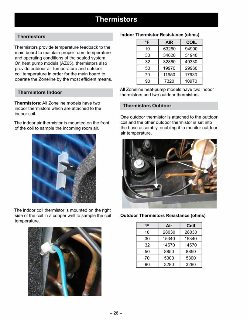
Thermistors: All Zoneline models have two indoor thermistors which are attached to the indoor coil.
The indoor air thermistor is mounted on the front of the coil to sample the incoming room air.
The indoor coil thermistor is mounted on the right side of the coil in a copper well to sample the coil temperature.
Indoor Thermistor Resistance (ohms)
All Zoneline heat-pump models have two indoor thermistors and two outdoor thermistors.
°F Air Coil10 28030 2803030 15340 1534032 14570 1457050 8850 885070 5300 530090 3280 3280
Thermistors Indoor
Thermistors Outdoor
Outdoor Thermistors Resistance (ohms)
°F AIR COIL10 63260 9490030 34620 5194032 32860 4933050 19970 2996070 11950 1793090 7320 10970
One outdoor thermistor is attached to the outdoor coil and the other outdoor thermistor is set into the base assembly, enabling it to monitor outdoor air temperature.

– 27 –
Controls
Main Board: Front Cover
MAIN BOARD
The new Zoneline series uses a main board that contains the microprocessor. It processes the information input from the User Interface (UI) or wall thermostat, the thermistors, and fan motors feedback. It then activates the associated relays for the selected cycle. The main board also has a DC power supply to provide the needed DC voltage to run the indoor and outdoor fan motors.
Personality is programmed into the board at the time of manufacture.
Service main boards will have “dip” switches to allow it to be set-up for the proper Zoneline model it will be installed in.
User Interface (UI) 12 pin
Red Aux Set Button
CDC / Motion Sensors
Remote Thermostat
RJ-45
Heater Personality
AC input
Indoor Thermistors

– 28 –
Power Cords
The new Zonelines have new power cords (sold separately). Three amperage ratings are available: 15-Amp (Part #: RAK315P), 20-Amp (Part #: RAK320P), and 30-Amp (Part #: RAK330P). All cords will have the LCDI protector built in.
In addition, the 20 and 30-amp cords will have a separate heater-enabling jumper that plugs into the main board which limits the heater wattage according to house supply limitations. If this jumper is not connected, the heater circuit will be limited to 15-amp operation.
All new cords are required for both series of Zonelines. They are redesigned to eliminate the AC jumper wires.
15-amp: No DC Harness
20-amp: Single Wire DC Harness
30-amp: Double Wire DC Harness

– 29 –
Main Board - Front
Removing the front cover exposes the indoor fan connector, the indoor thermistors, User Interface and indoor fan connectors are all located on the upper left portion of the main board.
Indoor Thermistors
RJ-45
A RJ-45 connector is mounted to the front of the main control board next to the red auxiliary set button of the main board to provide a way to easily update software or to hook up other monitoring devices. It is accessible by removing the front cover of the Zoneline.
Indoor Fan
User Interface (UI)
12 pin
Red Aux Set Button

– 30 –
Main Board
Outdoor Thermistor(s)
Outdoor Fan Motor
Heater plug
Compressor
DLB Relay
J305 ICR Pump
J304 Reversing Valve Coil
AC Input plug
J101 voltage select jumper• Jumper between 1 and 2
230V• Jumper between 1 and 3
265VThis jumper provide voltage to 24 VAC transformer and must be in place for Zoneline to function correctly.
Low Volt Transformer

– 31 –
NOTE: ALL RESISTANCES SHOWN ARE APPROXIMATIONS
* DC Motors: Resistances should read very high if at all, a lower reading indicates a defective motor.
Component Checks at Main Board
Thermistors
INDOORJ502 pin 1 - 2 AIR range 7k ohms to 64k ohmsJ502 pin 3 - 4 COIL range 10.5k ohms to 95k ohmsOUTDOORJ503 pin 1 - 2 AIR range 3k ohms to 28.5k ohmsJ503 pin 4 - 5 COIL range 3k ohms to 28.5k ohms
Indoor Fan Motor
*J103 pin 1 - 2 Blue to Yellow ∞J103 pin 3 - 4 White to Black 38.5k ohms approximatelyJ103 pin 3 - 6 White to Red ∞J103 pin 4 - 6 Black to Red ∞
Outdoor Fan Motor
*J104 pin 1 - 2 Blue to Yellow ∞J104 pin 3 - 4 White to Black 47k ohms approximatelyJ104 pin 3 - 6 White to Red 8meg ohms approximatelyJ104 pin 4 - 6 Black to Red ∞
ICR Pump J305 pin 1 - 2 Yellow to Yellow 260 ohms (230/208 models)
Reversing Valve Coil
J304 pin 1 - 2 Pink to Pink 1.5k ohms (230/208 models)
Heaters (230/208 models)
Plug Blue to Brown on relay 21 ohmsPlug Brown to Brown on relay 36 ohmsPlug Yellow to Brown on relay 50 ohms
∞ = Infinite

– 32 –
Fault Codes
Fault Code Display Mode
While the Zoneline is in the "OFF" mode, press and hold the fan button with the red auxiliary set button simultaneously to enter into this mode. The Zoneline will then display all active fault codes held in memory, showing each one for 3 seconds on/off.
If no codes are present, display will show "--" and flash that every 3 seconds on/off.
Displays all fault codes three times and then after an additional 30 seconds the Zoneline reverts to OFF mode. Pressing AUX will clear stored faults but it will not exit the fault code menu. Any other button press takes Zoneline out of this mode.
Fault Code
NumberFault Meaning Effect on Operation
While Fault is ACTIVE Fault Reset Time
F1 Indoor fan fault: Fan motor not moving at commanded speed after 30 seconds of drive voltage.
No resistance heating, fan, heat pump or cooling available.
Fault clears after 10 minutes.
F2 Outdoor fan fault: Fan motor not moving at commanded speed after 30 seconds of drive voltage.
No heat pump or cooling available. Resistance heating and fan only.
Fault clears after 10 minutes.
F3 External thermostat wiring: Applied signal is not valid and has been constant for 30 seconds.
No external control of fans, heat or cooling. Internal control operation only.
Clears once a valid signal is received.
F4 Indoor thermistor fault: One of the indoor thermistors is not reading valid temperatures. Valid range is -10°F to 140°F.
No resistance heating, fan, heat pump or cooling available. Fan only.
Clears once a valid signal is received.
F5 Outdoor thermistor fault: One of the outdoor thermistors is not reading valid temperatures. Valid range is -30°F to 140°F.
No cooling or heat pump operation. Resistance heating or fan only.
Clears once a valid signal is received.
F6 Compressor fault: No temperature change has been detected after 1 minute of running.
No effect. Fault clears after 3 minutes.
F7 Reversing valve fault: Temperature change not happening as control expects after 1 minute of running.
No cooling or heat pump operation. Resistance heating or fan only.
Fault clears after 3 minutes.
F8 Software fault No effect
F9 Indoor coil freeze fault: The temperature of the indoor coil has fallen below the freeze threshold of 34°F.
The compressor is shut down until the coil temperature recovers.
Fault clears once indoor coil temperature rises above 50°F.
(Continued next page)
Features may vary depending model number throughout this Service Guide.

– 33 –
Fault Code
NumberFault Meaning Effect on Operation
While Fault is ACTIVE Fault Reset Time
F10 Heat pump over-temperature fault. The temperature of the indoor coil is over 131°F.
The outdoor fan motor is shut down until the coil temperature recovers.
Fault clears once indoor coil temperature drops below 122°F.
F11 Inlet air temperature. Indoor air thermistor warmer than 95°F.
Shut off compressor and resistance heat operation until inlet thermistor temperature drops below 85°F.
Fault clears once air temperature drops below 85°F.
F13 Heater airflow fault: The main board detects too low of indoor fan speed.
No resistance heat or heat pump available.
Fault clears after X minutes.
F17 Outlet thermistor failure. Fault clears when thermistor reads value other than short circuit or open circuit.
No resistance heating available.
F18 Outlet temperature overheat. The outgoing air is too hot. Fault clears when air temperature drops below threshold.
No resistance heating available.
F19 Outlet temperature overheat. The outgoing air is too hot.
No resistance heating available.
F23 Make-up Air Module Fault Shuts Down MUAM, including MUAM compressor
F24 Make-up Air Module Vent Door Fault
This is set if the vent door state change validation fails.
No effect
F25 Abnormal Defrost Fault (heat pump models only). Set when five consecutive defrost cycles failed to warm outdoor coil above 68°F.
Locks out heat pump, locks out defrost.
Will self-clear after 4.5 days.
F26 Air Conditioning Lockout Fault (heat pump models only). Sets when outdoor ambient temperature drops below 35°F.
Locks out compressor cooling operation.
Will self-clear after Outdoor Ambient temperature rises above 40°F.

– 34 –
Service Mode
While the Zoneline is in "OFF" mode, press and hold the "+" and "-" buttons simultaneously with the red auxiliary set button to enter into this mode.
All LED's light up to indicate entry into Service mode.
These modes can be entered even if the Zoneline is in Class 2 mode.
Service Mode times out after 15 minutes of inactivity.
Minimum run times are not applicable in this mode. Compressor delay start times in service mode will be 10 minutes.
NOTE: Fault codes are stored in this mode but do not intervene with the Zoneline operation.
Press the Mode button to cycle through the run modes.
Press +/- to toggle on/off.
AZ4500
1. "CL": Cooling. Compressor, Indoor Fan, reversing valve, and Outdoor fan are energized. Fan speed is high.
2. "EH": Electric heat. Electric heater (all relays) and Indoor Fan are energized. Fan speed is high.
3. "IF": Indoor Fan only. Indoor fan is energized. Fan speed is high.
4. "OF": Outdoor Fan only. Outdoor fan is energized. Fan speed is high.
5. "S1": Indoor Ambient Air Sensor: Temperature will be displayed between -9°F and 99°F on screen after Zoneline has been in this mode for 10 seconds. (If no sensors are detected,
"--" will be displayed).
6. "S2": Indoor Coil Sensor: Temperature will be displayed between -9°F and 99°F on screen after Zoneline has been in this mode for 10 seconds.
7. "S5"
8. "UI": UI Test: Run the LED test sequence.
9. "So": Software version is displayed.
AZ6500
1. "CL": Cooling. Compressor, Indoor Fan, reversing valve, and Outdoor fan are energized. Fan speed is high.
2. "HP": Heat Pump. Compressor, Indoor Fan, and Outdoor fan are energized, reversing valve is not energized. Fan speed is high.
3. "EH": Electric Heat. Electric heater (all relays) and Indoor Fan are energized. Fan speed is high.
4. "IF": Indoor Fan only. Indoor fan is energized. Fan speed is high.
5. "OF": Outdoor Fan only. Outdoor Fan is energized. Fan speed is high.
6. "IC": ICR Pump: Pump only is activated. If equipped.
7. "dE": Defrost: Reverse cycle defrost (cooling without any fans) is activated to melt ice on outdoor coil.
8. "S1": Indoor Ambient Air Sensor: Temperature will be displayed between -9°F and 99°F on screen after Zoneline has been in this mode for 10 seconds. (If no sensor is detected, "--" will be displayed).
9. "S2": Indoor Coil Sensor: Temperature will be displayed between -9°F and 99°F on screen after Zoneline has been in this mode for 10 seconds.
10. "S3": Outdoor Air Sensor: Temperature will be displayed between -9°F and 99°F on screen after Zoneline has been in this mode for 10 seconds.
11. "S4": Outdoor Coil Sensor: Temperature will be displayed between -9°F and 99°F on screen after Zoneline has been in this mode for 10 seconds.
12. "Ui": UI test: Run the LED test sequence.
13. "So": Software version is displayed.
Service Mode

– 35 –
Accessing Controls
Behind the control area on the bulkhead is a cover which allows access to the capacitor and some connections to the control board.
Capacitor: The capacitor assists the compressor starting and lowers the running current.
WARNING: Move the protective shield and discharge the capacitor with proper insulated pliers and electrically rated gloves before attempting service.
To access the control connectors or remove the control. release the standoff.
Carefully lower the control to a service friendly position.

– 36 –
The low voltage transformer is mounted to the control board. If the Low Volt Transformer has failed, the main control will need to be replaced.
Low Voltage Transformer
Low Volt Transformer
Diagnosing Low Volt Transformer
To verify Low Volt Transformer operation, AC Volts may be checked on the Remote Thermostat Connector J401 pins 1 - 7. 24 VAC is normal.
Pin 1 Pin 7

– 37 –
Service Main Board
(Continued next page)
Personality Settings

– 38 –
When the unit is powered on after replacing the board, the display will show “P1”. Press the up pad (+) button until the display shows “P3” for engineering digit 5 models. Press the red “Aux” button to save and exit, then verify proper operation.
Switch S501-4ON: Make up air module equipped
Switch S502-3 and S502-4Are currently not used
Switch S502-2ON: 265V model only Outlet Air Thermistor equipped - locate on the louver assembly
Switch S502-1ON: Heat pipe equipped
Switch S501-2 S502-3
15k BTU OFF OFF12k BTU ON OFF9k BTU OFF ON7k BTU ON ON
Switch S502-1ON: AZ45OFF: AZ65

– 39 –
User Interface
The User Interface is a display board with tactile push button switches. There aren’t any processors contained on this board.
There is a ferrite ring that the harness connecting the boards wraps around to minimize Electro-Magnetic Interference (EMI).
Three screws secure the User Interface/Control Assembly to the chassis. The control slides to the right.
Three tabs secure the User Interface board to the Control Assembly.

– 40 –
Air System
Fan Motors
Both the indoor and outdoor fan motors are DC motors driven by the main board and provide feedback to the main board for proper speed confirmation.
Indoor Fan Motor
The indoor fan motor turns a blower wheel which is attached to the motor shaft with a 4-mm Allen screw. The opposite end of the blower wheel inserts into a bearing assembly.
The main board supplies high voltage DC to drive the fan motor and receives speed feedback from the motor.
The motor is secured with a bracket and two screws.
NOTE: If the blower should disengage the bearing on the left side, the end cap will have to be removed and the bearing repositioned on the shaft.
Indoor Blower Wheel
The indoor blower wheel is attached to the motor shaft with a 4-mm Allen screw. The opposite end of the blower wheel inserts into a bearing assembly.

– 41 –
Proper Bearing Placement
NOTE: When reinstalling the bearing, ensure the shaft goes directly into the bearing assembly. The image above shows proper placement of the bearing. Failure to install properly will result in a noise complaint.
Remove six screws to remove the end cap to access the bearing assembly. Two screws are used to secure the bracket attached to the indoor coil and end cap.
Indoor Fan Bearing Components: Indoor Fan Bearing

– 42 –
The outdoor fan shroud provides proper airflow through the outdoor coil and also supports the outdoor fan motor.
The outdoor fan shroud and motor assembly are attached to the base pan and outdoor coil assembly with twelve screws and a “sleeve” that slides over the shroud and outdoor coil assembly.
NOTE: An extension will make accessing the lower screws easier.
Slide the “sleeve” up to separate the shroud and outdoor coil assembly.
Outdoor Fan Motor Shroud

– 43 –
Outdoor Fan Motor
The outdoor fan motor turns a slinger fan blade, which is attached to the motor shaft with a 3/8-in. regular thread nut.
The motor is secured to the outdoor shroud with four 5/16-in. hex-head shoulder bolts.
NOTE: If the wire clip found below the motor breaks, secure the wire to the support with a wire tie.

– 44 –
Electric Heat
Heater
All models (with Electric Heat) of the new Zoneline have a three bank heater assembly. They have three thermal switches to protect the circuit; two are cycling (resettable) thermal switches and the one is a "one-shot" thermal switch.
Features may vary depending model number throughout this Service Guide.
The heater assembly sets on the base pan and is secured by two screws on the left end cap.
The thermal cut-outs are part of the heater assembly.

– 45 –
Heater Assembly
Heater Assembly
Remove six screws to remove the end cap to access the heater assembly. Two screws are used to secure the bracket attached to the indoor coil and end cap. After disconnecting the wire harness from the board and removing one ground screw, the heater assembly will slide out the left side of the Zoneline.

– 46 –
Condensate Removal
ICR System
The Internal Condensate Removal system consists of a small pump that is driven by the main board. The board supplies line voltage to the pump. *Defrost water that is collected in the rear base pan is pumped up into a trough that rests along the length of the indoor coil. Water from the trough drips down the indoor coil to add moisture to the indoor air and to reduce the amount of water in the base pan.
*ONLY during Heat Pump Mode.
The water that is collected through the normal process of air conditioning is collected in the rear base pan. To aid in dissipating this water, the outdoor fan blade has a ring around the blade that picks up the water and “slings” it onto the outer coil. This assists in removing heat from the coil when the Zoneline is in cooling mode.
When operating in the heat-pump mode, defrost water is also collected in base pan, but because outdoor temperatures may drop below freezing, the water level could cause the outdoor fan blade to freeze in the pan. To prevent this from occurring, a thermostatically operated drain pan plug is utilized. Located in the base pan, when the air temperature is above 65°F it is closed, and opens when the temperature drops below 45°F, lowering the water level in the base pan.
If water that is collected off the indoor coil is not draining back to the base pan, clean the drain trough exit located on the left side of the trough.
Slinger on Outdoor Fan Blade
ICR Pump
On some Zoneline models, an Internal Condensate Pump is mounted into the outer base pan. As with previous ICR models, this pump is designed to pump condensate water, which accumulates from the outdoor coil when in heat pump mode, up to the top of the indoor coil and allows the water to trickle down the coil to evaporate. This process cuts down on excessive water flowing out of the rear of the Zoneline and adds moisture to the indoor air.

– 47 –
This feature allows outside air into the room. The door is secured with two screws from the factory that must be removed upon installation if the customer would like to use this feature. The damper assembly consists of a door, filter, rod and wing nut. The wing nut can be loosened and the rod may be slid back which opens the door. It then can be locked into place by tightening the wing nut.
Damper Door Make-Up Air Module (MUAM)
(Continued next page)
The hospitality industry has many building and occupancy codes they must follow. One ofthose codes is for introducing fresh air into guest spaces. Past codes allowed fresh air to passunder the entry door or a separate vent into the room. Some GE Appliances Zonelines have a fresh air feature built into the product, this feature is called a Make Up Air Module. The feature includes a self-contained sealed system and control module with a motorized duct door system. This feature allows outdoor air to be conditioned and enter the room through a ducted bulkheadassembly.
The MUAM is designed to turn the compressor off when outdoor temperature is below 50°F orif relative humidity is lower than 55%. It will turn on when relative humidity is above 55%. Themodule is automatically turned on and off by the microcontroller contained within the module’selectrical box.
The system is comprised of two components which are the MUAM and the damper door. TheMUAM is attached to the base pan and includes all sealed system components, fans andcontrols for the MUAM. The damper door is an assembly that is separate from the module andis installed in the bulkhead opening.
Please refer to Auxiliary Set Button in the Operation section of this guide to turn the MUAM On or Off.
FansControlDamper Assembly

– 48 –
The module is secured with two screws and tabbed into a base plate mounted to the base pan. Some new zoning regulations require that incoming air be conditioned.
If troubleshooting the Make-Up Air Module with an amp probe, the amperage should be between .75 and 1-amp, measured on the blue wire of the Make-Up Air Module harness. This is dependent upon the line voltage.
If for some reason the customer doesn’t want to use the MUAM and complains of air coming through the Zoneline, a panel can be ordered and installed (Part #: WP76X21320) to block the outside opening.
As viewed from the front, the MUAM is located on the left side and located on the back side of the bulkhead. Some models may have a replaceable filter. Most properties will have their own maintenance personel do this replacement.
When the Zoneline is first powered, the MUAM cycles on and the damper assembly door closes, then two variable speed fans turn on. The fans run for approximately 30 seconds (speed will change) with the door closed. The MUAM monitors the fans running with door closed. After 30 seconds, the damper door opens and the control is able to detect a change in fan operation. The control is able to detect the air resistance when door is open and closed through current draw. If the control does not see a change, the damper door is considered inoperative in either the open or closed position and will set a Fault Code of 24 (replace the damper assembly). If the control detects a bad fan condition, a Fault Code of 23 will be logged (replace the module). After 30 seconds, the compressor will cycle on (if temperature and humidity requirements have been met). If the control detects the sealed system is not operating correctly, Fault Code 23 will be set and the module will need to be replaced. Located within the MUAM control box are a microcontroller, outdoor thermistor, sealed system thermistor and humidity sensor. MUAM components (except for damper assembly) are not available separately requiring the module to be replaced.
Connections on the main control to the MUAM are through J305 and J404 connectors located on the back of the control.
(Continued next page)

– 49 –
Occupancy Sensors (optional)*
A wireless door sensor (located on guest entry door) and motion sensor (ceiling or wall mount) communicate to the Zoneline through a Setback Module. The three components work collectively to determine whether the room is occupied or vacant. When the guest room door is opened and motion is sensed, the MUAM will turn on and remain running (depending outdoor temperature and humidity). When the door is opened again (the guest is exiting the room) and no motion is detected within five minutes, the MUAM will turn off. If someone is in the room and motion is detected or the door is again opened the MUAM will cycle back on.
CDC (Central Desk Control) (optional)*
“The CDC input on Zoneline is an occupancy control option which is operated by the Property Management. A field provided switch wired to the CDC connector can open/close the circuit to stop operation of the Zoneline when closed, and when open the Zoneline is operational. The CDC connector can be used with an occupancy detection system to, instead, control the operation of the MUAM. Such a system is optional and is enabled through the Aux menu. It should be noted that if an occupancy detection system is enabled with a digital Make Up Air (*DBM and *EBM) Model, Central Desk Control cannot be used at the same time.
If the occupancy system is the suspect failure (confirm that Auxiliary Settings are turned on, see Auxiliary Controls section and Auxiliary Set Button section), the diagnosis can be verified by unplugging the CDC connector. With the Zoneline turned off, the fans will be heard. If the fans cannot be heard, enter Service Mode to turn the fan speed higher to verify operation.
*Occupancy Sensors and CDC are Optional accessories, only one may be used
Zoneline
Guest Door
Door Sensor Motion SensorW
ireless Signal
Wireless Signal

– 50 –
Complete (cooling only) sealed system with all other components removed.
Install a new drier in the liquid line tube between the outdoor coil and the capillaries.
Indoor Coil
Reversing Valve
Capillaries
Compressor
DrierLiquid Line
Outdoor Coil
Features may vary depending model number throughout this Service Guide.
As with any refrigeration system, Zonelines have an indoor coil, outdoor coil, compressor and refrigerant metering device (capillary tubes). A drier is part of the sealed system now included from the factory.
Additionally, on heat pump models (AZ65), a reversing valve to switch the flow of refrigerant and a check valve to balance the system are parts of the sealed system.
A "tank" or reciever is part of some sealed systems in the Zoneline models. The tank allows for expansion of the refrigerant where required.
NOTE: A new drier MUST be installed anytime a sealed system is repaired.
Sealed System

– 51 –
Compressor
Wiring: Compressor Check
CAUTION: Risk of injury. Keep head clear of terminal area when cover is removed.
Keep head clear of terminal area when cover is removed.
Check windings first. If open or grounded, DO NOT apply power to compressor terminals.
Reversing Valve
*Shown with solenoid removed.
Reversing Valve Solenoid Coil
BTU/Size V Run Start7K/230V 5.139±7% Ω 6.032±7% Ω7K/265V 6.747±7% Ω 4.680±7% Ω9K/230V 3.319±7% Ω 2.635±7% Ω9K/265V 4.503±7% Ω 3.298±7% Ω
12K/230V 2.526±7% Ω 2.313±7% Ω12K/265V 3.296±7% Ω 2.505±7% Ω15K/230V 2.227±7% Ω 3.093±7% Ω15K/265V 2.840±7% Ω 3.225±7% Ω
Compressor Resistance
Resistance spec is reported as room temperature readings.
BTU Microfarads7k 15 uF +/- 5%9k 30 uF +/- 5%
12k and 15k 30 uF +/- 5%
Capacitor Microfarads
On heat-pump models, the refrigerant flow direction is controlled by the reversing valve assembly. In the cooling mode, the main board supplies line voltage to the solenoid coil, which causes the valve to switch flow direction. With no voltage applied to the solenoid coil, the valve will be in the heating mode.
The solenoid coil attaches to the valve body with a 5/16-in. hex-head bolt. The 230/208-volt coil has pink wires and measures approximately 1.5k ohms.

– 52 –
NOTE: Reversing valve assemblies will come complete with tubing, so excess heat will not be applied to the valve body.
Tank
On 7k and 9k heat-pump models, a receiver tank is included in the sealed system. This tank is soldered to the outdoor coil return line tube.
Check Valve
This valve allows the flow of refrigerant one way unimpeded, but in heat pump mode it closes and forces the refrigerant to go through an additional length of capillary tube. This helps balance the refrigerant system.
NOTE: Care must be taken when soldering in the new check valve. Thermal paste and a damp rag must be used on the middle portion of the assembly to prevent thermal damage to the internal check ball assembly.
Drier
All Zonelines will now have a drier factory installed. The drier must be replaced anytime sealed system repairs are performed.
NOTE: Driers are vacuumed packed and should only be opened when it is being installed. Driers opened and left to the open air become saturated and should be discarded if not used within 45 minutes.
Service Replacement Valve Assembly
Heat pump drier kit shown: Includes the check valve, drier, capillary jumper and process stub

– 53 –
Sealed System: Refrigerant Flow Cooling
Features may vary depending model number throughout this Service Guide.

– 54 –
Sealed System: Refrigerant Flow Heating
Features may vary depending model number throughout this Service Guide.

– 55 –
Recovery Process
Liquid Port Open
Vapor Port Closed
High Side Tap Valve(WX5X328)
Recovery Process
High Pressure Switch On
Filter
410A Recovery Cylinder
Recovery Hose Hook-Ups
Complete charging and recovery information for R410A is available in Service Guide 31-9192.

– 56 –
Charging Summary
Safety Switch
Charging Summary
Charging Hose Hook-Ups
Complete charging and recovery information for R410A is available in Service Guide 31-9192.
Model R410a (oz)AZ45E07DABW5 29 ozAZ45E07DACW5 29 ozAZ45E09DABW5 36 ozAZ45E09DACW5 36 ozAZ45E09DBMW5 36 ozAZ45E12DABW5 31 ozAZ45E12DACW5 31 ozAZ45E12DBMW5 37 ozAZ45E15DABW5 35 ozAZ45E15DACW5 35 ozAZ65H07DABW5 29 ozAZ65H07DACW5 29 ozAZ65H07DADW5 29 oz
Model R410a (oz)AZ65H07DBMW5 29 ozAZ65H09DABW5 36 ozAZ65H09DACW5 36 ozAZ65H09DADW5 36 ozAZ65H09DBMW5 36 ozAZ65H12DABW5 37 ozAZ65H12DACW5 37 ozAZ65H12DADW5 37 ozAZ65H12DBMW5 37 ozAZ65H15DABW5 35 ozAZ65H15DACW5 36 ozAZ65H15DADW5 36 oz
Refrigerant Charge

– 57 –
Features differ by Model. All features shown may not be on all models
Schematic/Wiring Diagram

– 58 –
New Accessories
RAK204D15C Sub-Base, 208/230-v, 15-A, w/ Power CordRAK204D20C Sub-Base, 208/230-v, 20-A, w/ Power CordRAK204D30C Sub-Base, 208/230-v, 30-A, w/ Power CordRAK204E15C Sub-Base, 265-v, 15-A, w/ Power CordRAK204E20C Sub-Base, 265-v, 20-A, w/ Power CordRAK204E30C Sub-Base, 265-v, 30-A, w/ Power CordRAK315P LCDI Power Cord, 208/230-v, 15-ARAK320P LCDI Power Cord, 208/230-v, 20-ARAK330P LCDI Power Cord, 208/230-v, 30-ARAK315SP Short, non-LCDI Sub-base Power Cord, 208/230-v, 15A, includes junction boxRAK320SP Short, non-LCDI Sub-base Power Cord, 208/230-v, 20A, includes junction boxRAK330SP Short, non-LCDI Sub-base Power Cord, 208/230-v, 30A, includes junction boxRAK315D Direct Connect Pigtail, 208/230-v, 15-A, includes junction boxRAK320D Direct Connect Pigtail, 208/230-v, 20-A, includes junction boxRAK330D Direct Connect Pigtail, 208/230-v, 30-A, includes junction boxRAK515P Short Power Cord, 265-v, 15-ARAK520P Short Power Cord, 265-v, 20-ARAK530P Short Power Cord, 265-v, 30-ARAK515D Direct Connect Pigtail, 265-v, 15-ARAK520D Direct Connect Pigtail, 265-v, 20-ARAK530D Direct Connect Pigtail, 265-v, 30-ARAK6053 Duct Adaptor for AZ45/65 series ZonelinesRAK7013 Duct Adaptor for AZ45/65 series Zonelines, Repl. AP6 A_B ZonelinesRAK7023 Duct transition for AZ45/65 series Zonelines, repl. AZC first generation Sanyo
modelsRAA64 Room Front Air Filters for AZ45/65 series Zonelines (10 pairs per box)RAF454 Room Front for AZ45/65 series ZonelinesRAKCDC 3-pin connector for CDC and External Fan applicationsRAK4002D Electrical junction box for direct connection applicationsRAB7116B 16-in. deep steel wall sleeve, color changeRAB7124B 24-in. deep steel wall sleeve, color changeRAB7118B 18-in. deep wall sleeve, color changeRAB7120B 20-in. deep wall sleeve, color change

– 59 –
Index
Aauxiliary settings 13
CCapacitor 35CDC 16, 25, 58Charging Summary 56Check Valve 52Control Lock Out 23
Ddrain pan plug 46drain trough 46Drier 52
EExternal Fan 25, 58
FFreeze Sentinel 23, 25
Hheater 9, 10, 13, 23, 28, 34, 44, 45heat sentinel 23
IICR system 22Indoor Fan Blade 40Indoor Fan Motor 31, 40Introduction 1
MMake Up Air Module 47, 56Mini Manual location 8Model Serial location 8
NNomenclature 8
Ooutdoor fan blade 7, 46outdoor fan motor 33, 42, 43Outdoor fan shroud 42
PPersonality 27Power Cord 58
RRecovery Process 55Refrigerant Flow Cooling 53Refrigerant Flow Heating 54Remote Thermostat 25REVERSING VALVE 30RJ-45 27, 29
SService Mode 34solenoid 51Stage Heating 11System Pressures 7
TThermal fuse 35Thermistors Indoor 26Thermistors Outdoor 26Tools Required 7
UUser Interface 39