2018 umc and imc code changes...• a list of mechanical standards that appear in specific sections...
TRANSCRIPT

i
Environmental Note:
In consideration of the environment, this handout has been designed to conserve
printing costs.
Contact:
IAPMO Training and Certification Department at: Chicago Regional Office 18927 Hickory Creek Dr., Suite 220 Mokena, IL 60448-8399 Email: [email protected] Toll free: 1-877-427-6601 Image Disclaimer:
The graphics and illustrations used in this course are presented for educational
purposes only. IAPMO does not endorse or recommend the vendor/product depicted,
nor any vendor or product. IAPMO makes no representations, warranties or guarantees
as to, and assumes no responsibility for, the product(s) depicted and IAPMO expressly
disclaims all liability for damages of any kind arising out of the use or performance of
the vendors, products or services depicted.
Copyright:
The content provided here is copyrighted material. Use of any of the material for other
than personal use is strictly prohibited without the written consent of the International
Association of Plumbing and Mechanical Officials (IAPMO).
Content Disclaimer
The information herein is provided for educational purposes only and shall not be
treated as an official interpretation of the referenced codes or standards. Always refer to
the complete code or standard when installing, replacing, or repairing any plumbing or
mechanical system.
1/15/2020
1
• Stars indicate
• Code changes
• New sections
• Language changes
• Or relocation of a section
2018 IMC
Chapter 2
Definitions
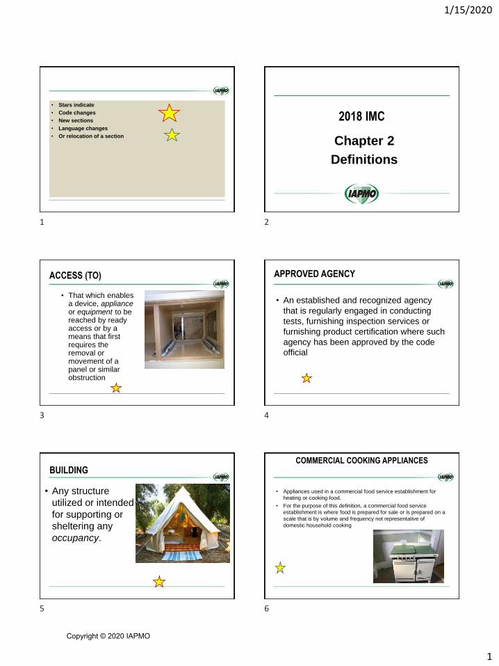
ACCESS (TO)
• That which enables a device, appliance or equipment to be reached by ready access or by a means that first requires the removal or movement of a panel or similar obstruction
APPROVED AGENCY
• An established and recognized agency
that is regularly engaged in conducting
tests, furnishing inspection services or
furnishing product certification where such
agency has been approved by the code
official
BUILDING
• Any structure
utilized or intended
for supporting or
sheltering any
occupancy.
COMMERCIAL COOKING APPLIANCES
• Appliances used in a commercial food service establishment for
heating or cooking food.
• For the purpose of this definition, a commercial food service
establishment is where food is prepared for sale or is prepared on a
scale that is by volume and frequency not representative of
domestic household cooking
1 2
3 4
5 6
Copyright © 2020 IAPMO
1/15/2020
2
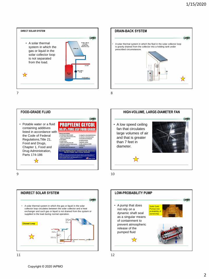
DIRECT SOLAR SYSTEM
• A solar thermal
system in which the
gas or liquid in the
solar collector loop
is not separated
from the load.
DRAIN-BACK SYSTEM
• A solar thermal system in which the fluid in the solar collector loop
is gravity drained from the collector into a holding tank under
prescribed circumstances
FOOD-GRADE FLUID
• Potable water or a fluid
containing additives
listed in accordance with
the Code of Federal
Regulations,Title 21,
Food and Drugs,
Chapter 1, Food and
Drug Administration,
Parts 174-186
HIGH-VOLUME, LARGE-DIAMETER FAN
• A low speed ceiling
fan that circulates
large volumes of air
and that is greater
than 7 feet in
diameter.
INDIRECT SOLAR SYSTEM
• A solar thermal system in which the gas or liquid in the solar
collector loop circulates between the solar collector and a heat
exchanger and such gas or liquid is not drained from the system or
supplied to the load during normal operation.
Closed Loop
LOW-PROBABILITY PUMP
• A pump that does
not rely on a
dynamic shaft seal
as a singular means
of containment to
prevent atmospheric
release of the
pumped fluid
Solid Gold
Pumps low
probability of
ownership
7 8
9 10
11 12
Copyright © 2020 IAPMO
1/15/2020
3
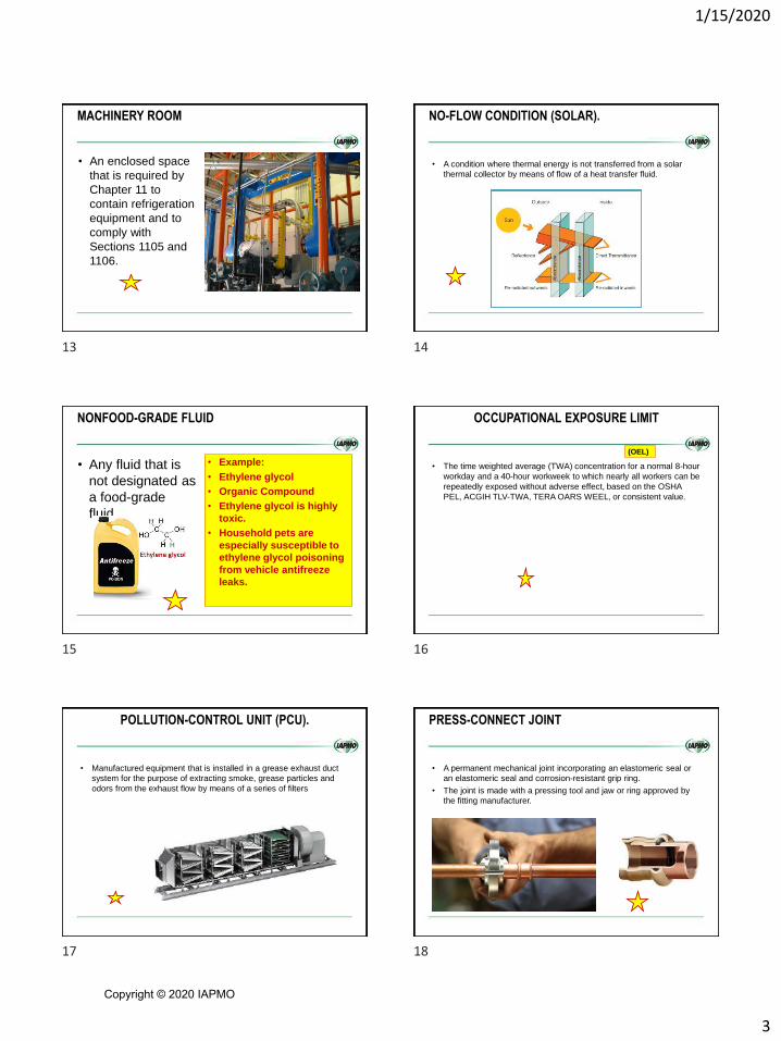
MACHINERY ROOM
• An enclosed space
that is required by
Chapter 11 to
contain refrigeration
equipment and to
comply with
Sections 1105 and
1106.
NO-FLOW CONDITION (SOLAR).
• A condition where thermal energy is not transferred from a solar
thermal collector by means of flow of a heat transfer fluid.
NONFOOD-GRADE FLUID
• Any fluid that is
not designated as
a food-grade
fluid.
• Example:
• Ethylene glycol
• Organic Compound
• Ethylene glycol is highly
toxic.
• Household pets are
especially susceptible to
ethylene glycol poisoning
from vehicle antifreeze
leaks.
OCCUPATIONAL EXPOSURE LIMIT
• The time weighted average (TWA) concentration for a normal 8-hour
workday and a 40-hour workweek to which nearly all workers can be
repeatedly exposed without adverse effect, based on the OSHA
PEL, ACGIH TLV-TWA, TERA OARS WEEL, or consistent value.
(OEL)
POLLUTION-CONTROL UNIT (PCU).
• Manufactured equipment that is installed in a grease exhaust duct
system for the purpose of extracting smoke, grease particles and
odors from the exhaust flow by means of a series of filters
PRESS-CONNECT JOINT
• A permanent mechanical joint incorporating an elastomeric seal or
an elastomeric seal and corrosion-resistant grip ring.
• The joint is made with a pressing tool and jaw or ring approved by
the fitting manufacturer.
13 14
15 16
17 18
Copyright © 2020 IAPMO

1/15/2020
4
SOLAR THERMAL SYSTEM
• A system that
converts solar
radiation to thermal
energy for use in
heating or cooling
2018 UMC
Chapter 2
Definitions
Air Dispersion Systems:
• Materials intended for
use in air handling
systems in exposed
locations operating
under positive
pressure.
Appliance definition
• A device that utilizes an energy source to produce light,
heat, power, refrigeration, air conditioning, or
compressed fuel gas.
• This definition also shall include a vented decorative
appliance
Appliance Categorized Vent Diameter/Area
• The minimum vent
area/diameter
permissible for
Category I appliances
to maintain a
nonpositive vent static
pressure.
205.0 Combustible Material
• A material that, in the form in which it is used
and under the conditions anticipated, will ignite
and burn; a material that does not meet the
definition of non-combustible.
19 20
21 22
23 24
Copyright © 2020 IAPMO

1/15/2020
5
Compensating Hood
• A hood for commercial food heat processing
equipment that has an outside-air supply with air
delivered below or within the hood
DIRECT-VENT APPLIANCES
• Appliances that are constructed and installed so that all air for combustion is derived from the outdoors and all flue gases are discharged to the outdoors.
Is this a direct vent appliance?
Joint, Press-Connect
• A permanent mechanical
joint consisting of an
elastomeric seal or an
elastomeric seal and
corrosion- resistant grip
ring.
• The joint is made with a
pressing tool and jaw or ring
approved by the fitting
manufacture
Line set
• A set of two
refrigerant pipes that
extends from the
condenser to the
evaporator (cooling
coil) in direct systems,
consisting of a suction
line and a liquid line.
Refrigeration System, Indirect
• A system in which a secondary coolant cooled or
heated by the refrigerating system is circulated
to the air or other substance to be cooled or
heated.
• Indirect systems are distinguished by the
method of application given below:
Indirect Open Spray System
• A system in which a
secondary coolant is
in direct contact with
the air or other
substance to be
cooled or heated
25 26
27 28
29 30
Copyright © 2020 IAPMO
1/15/2020
6
Double Indirect Open Spray System
• A system in which the secondary substance for
an indirect open spray system is heated or
cooled by the secondary coolant circulated from
a second enclosure
Indirect Closed System
• A system in which a secondary coolant
passes through a closed circuit in the air
or other substance to be cooled or heated.
[ASHRAE 15:5.1.2.3]
2018 IMC
Chapter 3
General Regulations
303.7 Pit locations
• Appliances installed in pits or excavations shall not come in direct
contact with the surrounding soil and shall be installed not less
than 3 inches above the pit floor.
• Excavation on the control side of the appliance shall extend not
less than 30 inches horizontally
303.9 Fireplaces in Group I-2, Condition 2
occupancies
• Fuel-burning appliances and fireplaces in Group I-2, Condition 2
occupancies shall be in accordance with Section 901.4.
Institutional Group I-2 occupancy shall include buildings and
structures used for medical care on a 24-hour basis for more than
five persons who are not capable of self-preservation.
This group shall include, but not be limited to, the
following:
Foster care facilities
Detoxification facilities
Hospitals
Nursing homes
Psychiatric hospitals
Copyright
901.4 Solid fuel-burning fireplaces and appliances areprohibited.
2018 Uniform Mechanical Code
Chapter 3
31 32
33 34
35 36
Copyright © 2020 IAPMO
1/15/2020
7
302.1 Materials – Standards and Alternates
• 302.1 Minimum Standards.
– Unless otherwise provided for in this code,
materials, appurtenances, or devices … shall
be submitted to the AHJ for approvalShows AHJ is the approval agency
302.1.2 Standards
• A list of mechanical standards that appear in specific
sections of this code is referenced in Table 1701.1.
Standards referenced in Table 1701.1 shall be applied as
indicated in the applicable referenced section.
• A list of additional standards, publications, practices and
guides that are not referenced in specific sections of this
code appear in Table 1701.2.
• The documents indicated in Table 1701.2 shall be
permitted in accordance with Section 302.2
303.1 Listed Appliances
• The installation of equipment and appliances regulated by this code
shall be in accordance with the conditions of the listing, the
manufacturer’s installation instructions and this code.
• The manufacturer’s installation and operating instructions shall be
attached to the appliance.
• Clearances of listed equipment and appliances from combustible
materials shall be as specified in the listing or on the rating plate.
303.3 Unlisted Appliances
• Except as otherwise permitted
• Unlisted equipment and appliances shall be approved by
the Authority Having Jurisdiction.
• Unlisted equipment and appliances shall be installed in
accordance with the manufacturer’s installation
instructions and with clearances from combustible
materials in accordance with Section 303.10 or
Section 303.10.1.
303.8 Equipment and Appliances on Roofs.
• Shall be designed or enclosed so as to
withstand climatic conditions in the area in which
they are installed.
• Where enclosures are provided, each enclosure
shall permit easy entry and movement
303.8 Equipment and Appliances on Roofs
• Equipment and appliances on roofs shall be
designed or enclosed so as to withstand climatic
conditions in the area in which they are installed.
37 38
39 40
41 42
Copyright © 2020 IAPMO
1/15/2020
8
303.8 Equipment and Appliances on Roofs
• Where enclosures are provided, each enclosure
shall:
• Permit easy entry and movement
• Be of reasonable height
• And shall have not less than a 30 inch clearance
between the entire service access panel(s) of
the equipment and appliance, and the wall of the
enclosure.
303.8.3 Installation of Equipment and
Appliances on Roofs.
• Equipment and
appliances shall be
installed in
accordance with the
manufacturer’s
installation
instructions. [NFPA
54:9.4.2.1]
• Correlates with UPC
Requirements
303.9 Avoiding Strain on Gas Piping.
• Appliances shall be
supported and
connected to the
piping so as not to
exert undue strain on
the connections.
[NFPA 54:9.1.17]
• Correlates with UPC
What’s wrong with the Installation?
303.10.1.1 Type I Hood Exhaust System
• Reduce clearances for Type I exhaust systems
shall be in accordance with Section 507.4.2
through Section 507.4.2.3.
• Clearances from the duct or the exhaust fan to
the interior surface of enclosures of combustible
construction shall be in accordance with Section
510.7.3 and clearances shall not be reduced.
303.10.1.2 Product Conveying Ducts
• Reduce clearances to combustibles
construction for product conveying ducts
shall be in accordance with
• Section 506.10.3 through Section
506.11.6.3. {New sections}
303.10.1.2 Product Conveying Ducts
• Reduce clearances to combustibles
construction for product conveying ducts
shall be in accordance with:
• Section 506.10.3 through Section
506.11.6.3.
43 44
45 46
47 48
Copyright © 2020 IAPMO

1/15/2020
9
303.10.1.3 Solid-Fuel Burning Appliances
• For solid-fuel burning
appliances, the
clearance, after
reduction, shall not be
less than 12 inches to
combustible walls and
not less than 18 inches
to combustible ceilings.
303.10.1.3 Solid-Fuel Burning Appliances
• The clearance, after reduction, shall be
permitted to be less than 12 inches to
combustible walls and less than 18 inches
to combustible ceilings where the solid-
fuel burning appliances is listed for lesser
clearance.
303.13 Pit Location
• Appliances installed in pits or excavations
1. Shall extend to a depth of 6 inches
2. The sides of the pit or excavation shall be held
back a minimum of 12 inches from the
appliance.
3. Where the depth exceeds 12 inches below
adjoining grade, the walls of the pit or
excavation shall be lined with concrete or
masonry.
Pit locations
4. Such concrete or masonry shall extend a
minimum of 4 inches above adjoining ground
level
www.iapmo.org
www.iapmolearn.org
Chapter 4 VENTILATION AIR SUPPLY
2018 IMC chapter 4
Ventilation
49 50
51 52
53 54
Copyright © 2020 IAPMO

1/15/2020
10
403.3.2.4 System controls
• Where provided within a dwelling unit, controls for outdoor air
ventilation systems shall include text or a symbol indicating the
system’s function.
403.3.2.5 Ventilating equipment
• Exhaust equipment serving single dwelling units shall be listed and
labeled to provide the minimum required air flow in accordance with
ANSI/AMCA 210-ANSI/ASHRAE 51.
404.1 Enclosed parking garages
• Mechanical ventilation systems for enclosed parking garages
shall operate continuously or shall be automatically operated by
means of carbon monoxide detectors applied in conjunction with
nitrogen dioxide detectors.
404.1 Enclosed parking garage
• Such detectors shall be listed in accordance with UL 2075 and
installed in accordance with their listing and the manufacturers’
instructions.
404.1 Enclosed parking garage
• Automatic operation shall cycle the ventilation system between the
following two modes of operation:
• 1. Full-on at an airflow rate of not less than 0.75 cfm per square foot
of the floor area served.
• 2. Standby at an airflow rate of not less than 0.05 cfm per square
foot of the floor area served.
55 56
57 58
59 60
Copyright © 2020 IAPMO

1/15/2020
11
2018 IMC chapter 4
Ventilation
61 62
63 64
65 66
Copyright © 2020 IAPMO
1/15/2020
12
401.0 General
This chapter contains requirements for
ventilation air supply, exhaust, and makeup air requirements
for occupiable spaces within a building.
CO Exhaust needs Make-up air Change air filters
often
402.2 Natural Ventilation
• Exceptions:
(2) A mechanical ventilation system is not required
where:
(a) natural ventilation openings comply with the
requirements of Section 402.2 and are
permanently open or have controls that
prevent the openings from being closed
during periods of expected occupancy or
(b) the zone is not served by heating or cooling
equipment. [ASHRAE 62.1:6.4]
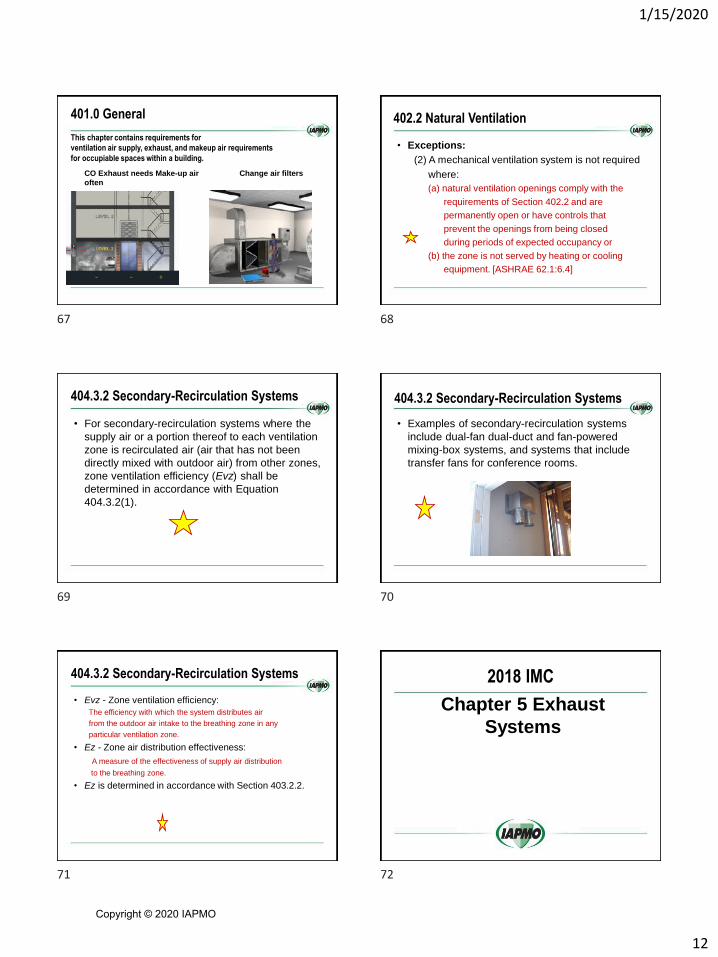
404.3.2 Secondary-Recirculation Systems
• For secondary-recirculation systems where the
supply air or a portion thereof to each ventilation
zone is recirculated air (air that has not been
directly mixed with outdoor air) from other zones,
zone ventilation efficiency (Evz) shall be
determined in accordance with Equation
404.3.2(1).
404.3.2 Secondary-Recirculation Systems
• Examples of secondary-recirculation systems
include dual-fan dual-duct and fan-powered
mixing-box systems, and systems that include
transfer fans for conference rooms.
404.3.2 Secondary-Recirculation Systems
• Evz - Zone ventilation efficiency:
The efficiency with which the system distributes air
from the outdoor air intake to the breathing zone in any
particular ventilation zone.
• Ez - Zone air distribution effectiveness:
A measure of the effectiveness of supply air distribution
to the breathing zone.
• Ez is determined in accordance with Section 403.2.2.
2018 IMC
Chapter 5 Exhaust
Systems
67 68
69 70
71 72
Copyright © 2020 IAPMO
1/15/2020
13
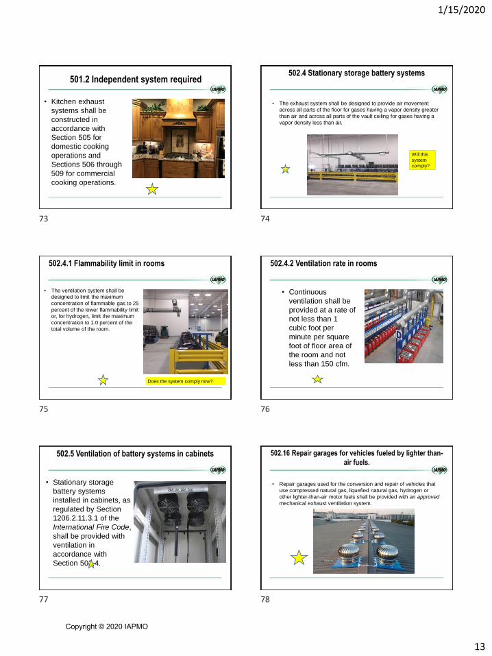
501.2 Independent system required
• Kitchen exhaust
systems shall be
constructed in
accordance with
Section 505 for
domestic cooking
operations and
Sections 506 through
509 for commercial
cooking operations.
502.4 Stationary storage battery systems
• The exhaust system shall be designed to provide air movement
across all parts of the floor for gases having a vapor density greater
than air and across all parts of the vault ceiling for gases having a
vapor density less than air.
Will this
system
comply?
502.4.1 Flammability limit in rooms
• The ventilation system shall be
designed to limit the maximum
concentration of flammable gas to 25
percent of the lower flammability limit
or, for hydrogen, limit the maximum
concentration to 1.0 percent of the
total volume of the room.
Does the system comply now?
502.4.2 Ventilation rate in rooms
• Continuous
ventilation shall be
provided at a rate of
not less than 1
cubic foot per
minute per square
foot of floor area of
the room and not
less than 150 cfm.
502.5 Ventilation of battery systems in cabinets
• Stationary storage
battery systems
installed in cabinets, as
regulated by Section
1206.2.11.3.1 of the
International Fire Code,
shall be provided with
ventilation in
accordance with
Section 502.4.
502.16 Repair garages for vehicles fueled by lighter than-
air fuels.
• Repair garages used for the conversion and repair of vehicles that
use compressed natural gas, liquefied natural gas, hydrogen or
other lighter-than-air motor fuels shall be provided with an approved
mechanical exhaust ventilation system.
73 74
75 76
77 78
Copyright © 2020 IAPMO

1/15/2020
14
502.16 Repair garages for vehicles fueled by lighter than-
air fuels.
• The mechanical exhaust ventilation system shall be in accordance
with Section 502.16.1 or 502.16.2 as applicable
502.16 Exceptions:
1. Repair garages where work is not performed on
the fuel system and is limited to exchange of
parts and maintenance not requiring open flame
or welding on the compressed natural gas,
liquefied natural gas, hydrogen or other lighter-
than-air-fueled motor vehicle.
502.16 Exceptions:
2. Repair garages for hydrogen-fueled vehicles
where work is not performed on the hydrogen
storage tank and is limited to the exchange of parts
and maintenance not requiring open flame or
welding on the hydrogen-fueled vehicle.
• During the work, the entire hydrogen fuel system
shall contain a quantity of hydrogen that is less than
200 cubic feet.
502.16.1 Repair garages for hydrogen-fueled
vehicles
• Repair garages used for the repair of hydrogen-fueled vehicles shall
be provided with an approved exhaust ventilation system in
accordance with this code and
• Chapter 6 of NFPA 2.
502.16.2 Exhaust ventilation system
• Repair garages used for the repair of compressed natural gas,
liquefied natural gas or other lighter-than-air motor fuel, other than
hydrogen, shall be provided with an approved mechanical exhaust
ventilation system.
Indoor fueling and repair
79 80
81 82
83 84
Copyright © 2020 IAPMO

1/15/2020
15
502.16.2 Exhaust ventilation system
• The mechanical exhaust ventilation system shall be in accordance
with this code and Sections 502.16.2.1 and 502.16.2.2.
502.16.2 Exhaust ventilation system
• Exception:
• Where approved, natural
ventilation shall be an
alternative to mechanical
exhaust ventilation.
502.16.2.1 Design
• For indoor locations, air supply inlets and exhaust outlets for
mechanical ventilation shall be arranged to provide uniformly
distributed air movement with inlets uniformly arranged on walls
near floor level and outlets located at the high point of the room in
walls or the roof.
502.16.2.1 Design
• Failure of the exhaust
ventilation system
shall cause the
fueling system to shut
down.
• The exhaust
ventilation rate shall
be not less than 1
cubic foot per minute
per 12 cubic feet of
room volume.
502.16.2.2 Operation
• The mechanical exhaust ventilation system shall operate
continuously.
• Exceptions:
• 1. Mechanical exhaust ventilation systems that are interlocked with a
gas detection system designed in accordance with the International
Fire Code.
502.16.2.2 Operation
2. Mechanical exhaust ventilation systems in
garages that are used only for the repair of
vehicles fueled by liquid fuels or odorized gases,
such as compressed natural gas, where the
exhaust ventilation system is electrically
interlocked with the lighting circuit.
85 86
87 88
89 90
Copyright © 2020 IAPMO
1/15/2020
16
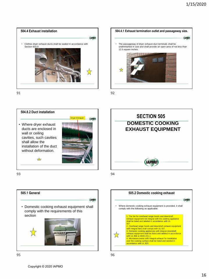
504.4 Exhaust installation
• Clothes dryer exhaust ducts shall be sealed in accordance with
Section 603.9
504.4.1 Exhaust termination outlet and passageway size.
• The passageway of dryer exhaust duct terminals shall be
undiminished in size and shall provide an open area of not less than
12.5 square inches.
504.8.2 Duct installation
• Where dryer exhaust
ducts are enclosed in
wall or ceiling
cavities, such cavities
shall allow the
installation of the duct
without deformation.
Dryer Exhaust
DOMESTIC COOKING
EXHAUST EQUIPMENT
SECTION 505
505.1 General
• Domestic cooking exhaust equipment shall
comply with the requirements of this
section
505.2 Domestic cooking exhaust
• Where domestic cooking exhaust equipment is provided, it shall
comply with the following as applicable:
1. The fan for overhead range hoods and downdraft
exhaust equipment not integral with the cooking appliance
shall be listed and labeled in accordance with UL
507.
2. Overhead range hoods and downdraft exhaust equipment
with integral fans shall comply with UL 507.
3. Domestic cooking appliances with integral downdraft
exhaust equipment shall be listed and labeled in accordance
with UL 858 or ANSI Z21.1.
4. Microwave ovens with integral exhaust for installation
over the cooking surface shall be listed and labeled in
accordance with UL 923.
91 92
93 94
95 96
Copyright © 2020 IAPMO

1/15/2020
17
505.3 Exhaust ducts
• Installations in Group I-1 and I-2 occupancies shall be in accordance
with the International Building Code and Section 904.13 of the
International Fire Code.
904.13 Domestic cooking systems in Group I-2
Condition 1
• In Group I-2 Condition 1 occupancies where cooking facilities are
installed in accordance with Section 407.2.6 of the International
Building Code
407.2.6 Nursing home cooking facilities
• In Group I-2, Condition 1, occupancies, rooms or spaces that
contain a cooking facility with domestic cooking appliances shall be
permitted to be open to the corridor where all of the following criteria
are met:
407.2.6 Nursing home cooking
1. The number of care recipients housed in the smoke compartment is not greater than 30.
2. The number of care recipients served by the cooking facility is not greater than 30.
3. Only one cooking facility area is permitted in a smoke compartment.
4. The types of domestic cooking appliances permitted are limited to ovens, cooktops, ranges, warmers and microwaves.
5. The corridor is a clearly identified space delineated by construction or floor pattern, material or color.
6. The space containing the domestic cooking facility shall be arranged so as not to obstruct access to the required exit.
407.2.6 Nursing home cooking
7. A domestic cooking hood installed and constructed in accordance with Section 505 of the International Mechanical Code is provided over the cooktop or range.
8. The domestic cooking hood provided over the cooktop or range shall be equipped with an automatic fire extinguishing system of a type recognized for protection of domestic cooking equipment.
• Pre-engineered automatic extinguishing systems shall be tested in accordance with UL 300A and listed and labeled for the intended application.
• The system shall be installed in accordance with this code, its listing and the manufacturer's instructions.
407.2.6 Nursing home cooking
9. A manual actuation device for the hood suppression system shall be
installed in accordance with Sections 904.12.1 and 904.12.2.
10. An interlock device shall be provided such that upon activation of
the hood suppression system, the power or fuel supply to the
cooktop or range will be turned off.
11. A shut-off for the fuel and electrical power supply to the cooking
equipment shall be provided in a location that is accessible only to
staff.
12. A timer shall be provided that automatically deactivates the
cooking appliances within a period of not more than 120 minutes.
13. A portable fire extinguisher shall be installed in accordance with
Section 906 of the International Fire Code.
97 98
99 100
101 102
Copyright © 2020 IAPMO
1/15/2020
18
904.13 Domestic cooking systems in Group I-2 Condition 1
• The domestic cooking hood provided over the cooktop or range shall
be equipped with an automatic fire-extinguishing system of a type
recognized for protection of domestic cooking equipment.
• Pre-engineered automatic extinguishing systems shall be tested in
accordance with UL 300A and listed and labeled for the intended
application.
• The system shall be installed in accordance with this code, its listing
and the manufacturer's instructions
904.13.1 Manual system operation and
interconnection
• Annual actuation and system
interconnection for the hood suppression
system shall be in accordance with
Sections 904.12.1 and 904.12.2,
respectively.
904.13.2 Portable fire extinguishers for domestic
cooking equipment in Group I-2 Condition 1
• A portable fire
extinguisher
complying with
Section 906 shall be
installed within a
30-foot distance of
travel from domestic
cooking appliances
505.6 Other than Group R
• In other than Group R occupancies, where domestic cooktops,
ranges, and open-top broilers are used for domestic purposes,
domestic cooking exhaust systems shall be provided.
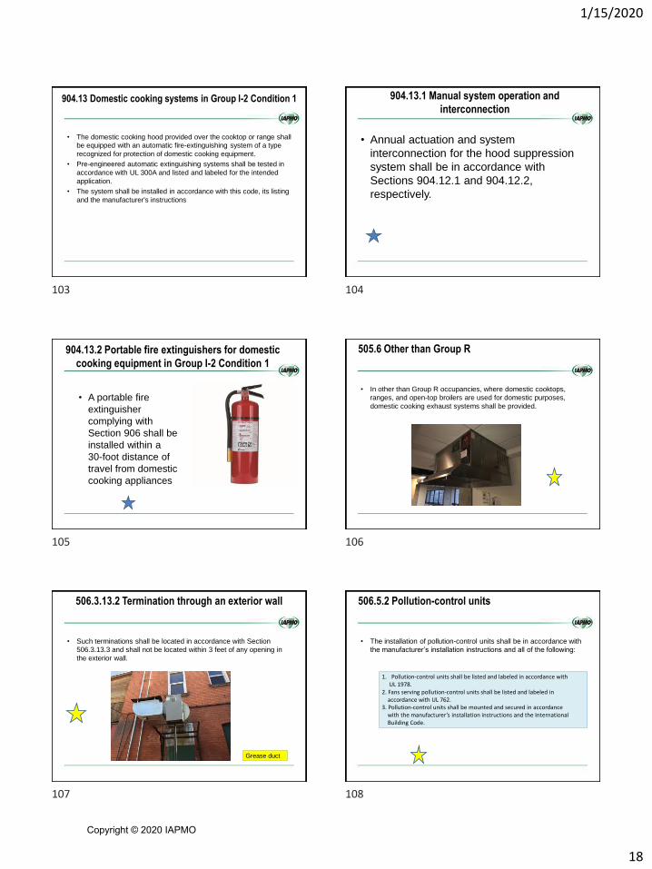
506.3.13.2 Termination through an exterior wall
• Such terminations shall be located in accordance with Section
506.3.13.3 and shall not be located within 3 feet of any opening in
the exterior wall.
Grease duct
506.5.2 Pollution-control units
• The installation of pollution-control units shall be in accordance with
the manufacturer’s installation instructions and all of the following:
1. Pollution-control units shall be listed and labeled in accordance with UL 1978.
2. Fans serving pollution-control units shall be listed and labeled in accordance with UL 762.
3. Pollution-control units shall be mounted and secured in accordance with the manufacturer’s installation instructions and the InternationalBuilding Code.
103 104
105 106
107 108
Copyright © 2020 IAPMO

1/15/2020
19
506.5.2 Pollution-control units
4. Pollution-control units located indoors shall be listed and labeled for
such use.
• Where enclosed duct systems, as required by Section 506.3.11, are
connected to a pollution control unit, such unit shall be located in a room
or space having the same fire-resistance rating as the duct enclosure.
• Access shall be provided for servicing and cleaning of the unit.
• The space or enclosure shall be ventilated in accordance with the
manufacturer’s installation instructions.
5. A clearance of not less than 18 inches shall be maintained between the
pollution-control unit and combustible material.
506.5.2 Pollution-control units
6. Roof-mounted pollution-control units shall be
listed for outdoor installation and shall be
mounted not less than 18 inches above the roof.
7. Exhaust outlets for pollution-control units shall be
in accordance with Section 506.3.13.
506.5.2 Pollution-control units
8. An airflow differential pressure control shall be
provided to monitor the pressure drop across the
filter sections of a pollution-control unit.
• When the airflow is reduced below the design velocity, the airflow
differential pressure control shall activate a visual alarm located in
the area where cooking operations occur.
9. Pollution-control units shall be provided with a
factory-installed fire suppression system.
506.5.2 Pollution-control units
10. Service space shall be provided in accordance with the
manufacturer’s instructions for the pollution-control unit and
The requirements of Section 306.
11. Wash-down drains shall discharge through a grease
Interceptor and shall be sized for the flow.
• Drains, shall be sealed with a trap or other approved means
to prevent air bypass.
• Where a trap is utilized it shall have a seal depth that
accounts for the system pressurization and evaporation
between cleanings.
506.5.2 Pollution-control units
12. Protection from freezing shall be provided for thewater supply and fire suppression systems wheresuch systems are subject to freezing.
13. Duct connections to pollution-control units shallbe in accordance with Section 506.3.2.3. Wherewater splash or carryover can occur in the transitionduct as a result of a washing operation, thetransition duct shall slope downward toward thecabinet drain pan for a length not less than 18 inches.
• Ducts shall transition to the full size of the unit’s inlet and outlet openings.
506.5.2 Pollution-control units
14. Extra-heavy-duty appliance exhaust systems shall not be connected to pollution-control units except where such units are specifically designed and listed for use with solid fuels.
15. Pollution-control units shall be maintained inaccordance with the manufacturer’s instructions.
109 110
111 112
113 114
Copyright © 2020 IAPMO

1/15/2020
20
507.2.6 Clearances for Type I hood
2. Type I hoods listed and labeled for clearances
less than 18 inches in accordance with
UL 710 shall be installed with the clearances
specified by such listings.
SECTION 509 - FIRE SUPPRESSION SYSTEMS
• 509.1 Where required.
• Cooking appliances required by Section 507.2 to have a Type I hood
shall be provided with an approved automatic fire suppression
system complying with the International Building Code and the
International Fire Code.
510.8.1 Duct cleanout
• Ducts conveying combustible dust as part of a dust
collection system shall be equipped with cleanouts that
are provided with approved access, predesigned to be
disassembled for cleaning, or engineered for automatic
cleanouts.
• Where provided, cleanouts shall be located at the base
of each vertical duct riser and at intervals not exceeding
20 feet in horizontal sections of duct.
513.6.1 Minimum pressure difference
• The pressure
difference across a
smoke barrier used
to separate smoke
zones shall be not
less than 0.05-inch
water gage in fully
sprinklered
buildings.
513.12.4 Automatic control
• Where complete automatic control is required or
used, the automatic control sequences shall be
initiated from an appropriately zoned automatic
sprinkler system complying with Section
903.3.1.1 of the International Fire Code, from
manual controls provided with ready access for
the fire department, and any smoke detectors
required by engineering analysis.
2018 UMC
Chapter 5 Exhaust
Systems
115 116
117 118
119 120
Copyright © 2020 IAPMO

1/15/2020
21
504.3 Domestic Range
• Ducts used for domestic kitchen range or
cooktop ventilation shall be of metal and shall
have smooth interior surfaces.
504.4 Clothes Dryers
• Transition ducts used to connect the dryer to the exhaust duct shall be listed and labeled in accordance with UL 2158A, or installed in accordance with the clothes dryer manufacturer’s installation instructions.
504.2 Independent Exhaust Systems
• Single or combined mechanical systems shall be
independent of other exhaust systems.
Dryer vent installed in combination with a water
heater or boiler vent is hazardous.
504.4 Clothes Dryers
• A clothes dryer
exhaust duct shall not
be connected to a
vent connector, gas
vent, chimney, and
shall not terminate
into a crawl space,
attic, or other
concealed space.
Dryer Vent
504.4.2.1 Length Limitation
• Unless otherwise permitted or required by the dryer
manufacturer’s instructions and approved by the
Authority Having Jurisdiction, domestic dryer moisture
exhaust ducts
shall not exceed a total combined horizontal and
vertical length of 14 feet including two 90 degree
elbows.
A length of 2 feet shall be deducted for each 90
degree elbow in excess of two.
504.4.2.1 Length Limitation
• Exception:
• Where an exhaust duct power ventilator, in
accordance with Section 504.4.2.3, is used, the
maximum length of the dryer exhaust duct shall
be permitted to be in accordance with the dryer
exhaust duct power ventilator manufacturer’s
installation instructions.
121 122
123 124
125 126
Copyright © 2020 IAPMO
1/15/2020
22
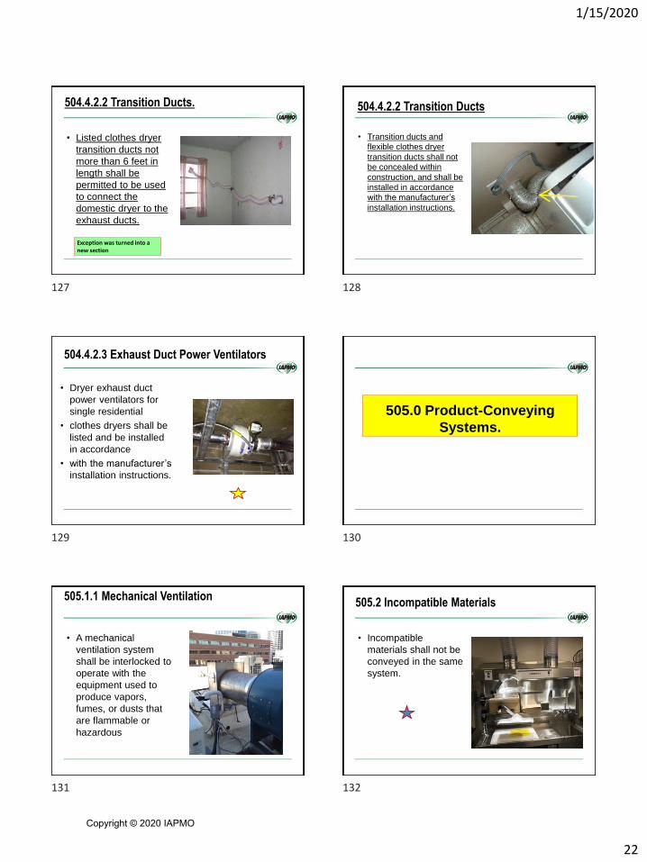
504.4.2.2 Transition Ducts.
• Listed clothes dryer
transition ducts not
more than 6 feet in
length shall be
permitted to be used
to connect the
domestic dryer to the
exhaust ducts.
Exception was turned into a new section
504.4.2.2 Transition Ducts
• Transition ducts and
flexible clothes dryer
transition ducts shall not
be concealed within
construction, and shall be
installed in accordance
with the manufacturer’s
installation instructions.
504.4.2.3 Exhaust Duct Power Ventilators
• Dryer exhaust duct
power ventilators for
single residential
• clothes dryers shall be
listed and be installed
in accordance
• with the manufacturer’s
installation instructions.
505.0 Product-Conveying
Systems.
505.1.1 Mechanical Ventilation
• A mechanical
ventilation system
shall be interlocked to
operate with the
equipment used to
produce vapors,
fumes, or dusts that
are flammable or
hazardous
505.2 Incompatible Materials
• Incompatible
materials shall not be
conveyed in the same
system.
127 128
129 130
131 132
Copyright © 2020 IAPMO

1/15/2020
23
505.4 Air-Moving Devices
• Air-moving devices
shall be sized to
establish the velocity
required to capture,
control, and convey
materials through the
exhaust system
505.5 Generating Flames, Sparks, or Hot Materials
• Operations generating flames, sparks, or hot material such as from grinding wheels and welding shall not be manifolded into an exhaust system that air conveys flammable or combustible materials
505.6 Fire Dampers
• Fire dampers shall be permitted to be installed in exhaust systems in accordance with the following:(1) Where ducts pass through fire barriers(2) Where a collection system installed on the end of the
system is protected with an automatic extinguishing system
(3) Where the duct system is protected with an automatic
extinguishing system
(4) Where ducts have been listed with interrupters
(5) Where necessary to facilitate the control of smoke
pursuant to the applicable NFPA standards [NFPA
91:4.2.9]
505.6.1 Prohibited
• Fire dampers shall
not be installed if the
material being
exhausted is toxic
and if a risk
evaluation indicates
that the toxic hazard
is greater than the fire
hazard.
505.7 Fire Detection and Alarm Systems
• Unless the conditions
in Section 505.7.1 or
Section 505.7.2 exist,
fire detection and
alarm systems shall
not be interlocked to
shut down air-moving
devices. [NFPA
91:4.2.14]
505.7.1 Automatic Extinguishing System
• Where shutdown is necessary for the effective operation of an automatic extinguishing system, it shall be permitted to interlock fire detection and alarm systems to shut down air-moving devices. [NFPA 91:4.2.14.1]
133 134
135 136
137 138
Copyright © 2020 IAPMO

1/15/2020
24
505.7.2 Shut Down Permitted
• Where a documented risk analysis acceptable to
the Authority Having Jurisdiction shows that the
risk of damage from fire and the products of
combustion would be higher with air-moving
devices operating, it shall be permitted to
interlock fire detection and alarm systems to
shut down air-moving devices. [NFPA
91:4.2.14.2]
506.3 Penetrations
• Exhaust ducts shall not pass through fire walls,
as defined by NFPA 221. [NFPA 91:4.2.11]
506.3.1 Fire Barriers
• Exhaust ducts passing through a fire barrier having a fire
resistance rating of 2 hours or more shall meet one of
the following specifications:
(1) Wrapped or encased with listed or
approved materials having a fire
resistance rating equal to the fire barrier
for 10 feet of the duct on each side of the
fire barrier including duct supports within
this span.
506.3.1 Fire Barriers
• (2) Constructed of
materials and
supports having a
minimum fire
resistance rating
equal to the fire
barrier.
506.3.1 Fire Barriers
• (3) Enclosed with a shaft that is constructed of
material having a fire resistance rating equal to
the fire barrier for 10 feet of the duct on each
side of the fire barrier with no inlets to the duct
within this distance, and the duct entry into and
exit from the shaft is protected in accordance
with Section 506.3.2. [NFPA 91:4.2.12]
506.3.2 Protection
• Exhaust ducts passing through fire barriers of
any fire resistance rating shall be protected by
sealing the space around the duct with listed or
approved fire stopping having a fire resistance
rating equal to the fire resistance rating of the
fire barrier. [NFPA 91:4.2.13]
139 140
141 142
143 144
Copyright © 2020 IAPMO
1/15/2020
25
506.4 Condensate
• Joints in duct
construction shall be
liquid tight when the
conveying system
contains condensable
vapors or liquids in
suspension.
• [NFPA 91:4.3.6.1]
506.4.1 Drainage
• Provisions shall be
made for drainage of
condensate at low
points in the duct.
[NFPA 91:4.3.6.2]
506.10 Duct Clearances
• Unless the conditions in Section 506.10.1 or
Section 506.10.2 exist, duct systems and system
components shall have a clearance of at least 6
inches from stored combustible materials, and
not less than 1⁄2 of an inch clearance from
combustible construction.
• [NFPA 91:4.7.1]
506.10.1 Protection Provided
• Where stored combustible material or
combustible construction is protected from
ductwork by the use of materials or products
listed for protection purposes, clearance shall be
maintained in accordance with those listings.
[NFPA 91:4.7.1.1]
506.10.2 Systems Conveying Combustible
Materials
• Unless the conditions in Section 506.10.3 exist,
duct systems and system components handling
combustible material shall have a clearance of
not less than 18 inches from combustible
construction or a combustible material.
• [NFPA 91:4.7.2]
506.10.3 Reduced Clearance Permitted
• When the ductwork system is operating at 140°F
or below and is equipped with an approved
automatic extinguishing system designed for the
specific hazard, the clearance shall be permitted
to be reduced to 6 inches from combustible
materials and 1 ⁄ 2 of an inch from combustible
construction. [NFPA 91:4.7.2.1]
145 146
147 148
149 150
Copyright © 2020 IAPMO
1/15/2020
26
506.10.4 Clearance Increases
• All duct systems and system components operating at temperatures above 140°F shall have clearances from stored combustible materials or combustible construction not less than those listed in Table 506.10.4.
• [NFPA 91:4.7.3]
506.11.4 Duct and Thermal Shield
• With all clearance
reduction systems,
not less than 1 inch
clear space shall be
provided between the
duct and the thermal
shield.
• [NFPA 91:4.7.4.5]
508.1 Where Required
• For the purpose of this section, a food-
processing establishment shall include a
building or portion thereof used for the
processing of food, but shall not include a
dwelling unit.
508.10.2 Noncanopy-Type Hoods.
• Noncanopy-type commercial
cooking hoods shall be installed
and sized in accordance with the
manufacturer’s installation
instructions, and Section 508.4.2.1
and Section 508.4.2.2.
• Exception: Listed hood
assemblies designed and installed
specifically for the intended use.
The code only addressed size and locations for canopy-type hoods but not for non-canopy-type hoods.
151 152
153 154
155 156
Copyright © 2020 IAPMO
1/15/2020
27
508.4.10.3 Labeling.
• Type I hoods shall
bear a label indicating
the exhaust flow rate
in cubic feet per
minute per lineal foot.
Hoods are designed in accordance with the appliance in which they are installed and the addition of a label will ensure, if the existing appliance is replaced, that the hood is of sufficient capacity to handle the exhaust of the replacement appliance.
519.0 Type II Hood
Exhaust System
Requirements
519.1 Where Required
• Type II hoods shall be installed above equipment and
dishwashers that generate steam, heat, and products of
combustion, and where grease or smoke is not present
519.0 Type II Hood Exhaust System
Requirements
• Exceptions:
• (1) Dishwashing machines connected to a Type
II duct system and exhausted directly to the
outdoors.
519.6 Makeup Air. Makeup air shall be provided in accordancewith Section 511.3.
519.0 Type II Hood Exhaust System Requirements
(2) Dishwashing machines with a self-contained
condensing system listed in accordance with UL
921 and installed in a space where the HVAC
system has been engineered to accommodate
the latent and sensible heat load emitted from
such appliances as approved by the Authority
Having Jurisdiction.
• Such equipment shall be provided with an
interlocking device to prevent opening of the
appliance prior to completion of its cycle.
519.6 Makeup Air
• Makeup air shall be provided in accordance with
Section 511.3.
157 158
159 160
161 162
Copyright © 2020 IAPMO
1/15/2020
28
2018 IMC
Chapter 6 – DUCT
SYSTEMS
Materials within
plenums
Plenums
SECTION 602 PLENUMS
• 602.1 General
• Supply, return, exhaust, relief and ventilation air plenums shall be
limited to uninhabited crawl spaces, areas above a ceiling or below
the floor, attic spaces, mechanical equipment rooms and the
framing cavities addressed in Section 602.3.
602.2.1 Materials within plenums
• 5. Combustible materials fully enclosed within one
of the following:
5.3. Materials listed and labeled for installation
within a plenum and listed for the application.
602.2.1.1 Wiring
• Combustible electrical wires and cables and optical fiber cables
exposed within a plenum shall:
1. Be listed and labeled as having a peak
optical density not greater than 0.50
2. An average optical density not greater than
0.15,
3. A flame spread distance not greater than 5
feet when tested in accordance with NFPA
262,
4. or shall be installed in metal raceways or
metal sheathed cable. Section was
a Re-Write
602.2.1.1 Wiring
• Combustible optical fiber and communication raceways exposed
within a plenum shall:
1. Be listed and labeled as having a peak
optical density not greater than 0.5
2. An average optical density not greater than
0.15
3. A flame spread distance not greater than 5
feet when tested in accordance with UL
2024. Only plenum-rated wires and cables shall be installed in plenum-rated
raceways.
Section was
a Re-Write
163 164
165 166
167 168
Copyright © 2020 IAPMO

1/15/2020
29
602.2.1.2 Fire sprinkler piping
• Plastic fire sprinkler piping exposed within a plenum shall:
1. Be used only in wet pipe systems
2. Shall be listed and labeled as having a peak
optical density not greater than 0.50
3. An average optical density not greater than
0.15
4. A flame spread distance not greater than 5
feet when tested in accordance with UL 1887.
Section was
a Re-Write
602.2.1.3 Pneumatic tubing
• Combustible pneumatic tubing exposed within a plenum shall
1. Shall be listed and labeled as having a peak
optical density not greater than 0.50
2. An average optical density not greater than
0.15
3. A flame spread distance not greater than 5
feet when tested in accordance with UL 1820
Section was
a Re-Write
602.2.1.6 Foam plastic in plenums as interior finish or
interior trim
• Foam plastic in plenums used as interior wall or
ceiling finish or interior trim shall exhibit
1. A flame spread index of 25 or less
2. A smoke-developed index of 50 or less
• When tested in accordance with ASTM E84 or UL 723 at
the maximum thickness and density intended for use,
and shall be tested in accordance with NFPA 286 and
meet the acceptance criteria of Section 803.1.2 of the
International Building Code.
602.2.1.6 Foam plastic in plenums as interior finish or
interior trim
• As an alternative to testing to NFPA 286, the foam plastic shall be
approved based on test conducted in accordance with Section
2603.9 of the International Building Code.
602.2.1.6 Foam plastic in plenums
• Exceptions:
1. Foam plastic in plenums used as interior wall or ceiling finish
or interior trim shall exhibit a flame spread index of 75 or
less and a smoke developed index of 450 or less when
tested in accordance with ASTM E84 or UL 723 at the
maximum thickness and density intended for use, where it is
separated from the airflow in the plenum by a thermal barrier
complying with Section 2603.4 of the International Building
Code.
602.2.1.6 Foam plastic in plenums
• Exceptions:
2. Foam plastic in plenums used as interior wall or ceiling
finish or interior trim, shall exhibit a flame spread index of
75 or less and a smoke developed index of 450 or less
when tested in accordance with ASTM E84 or UL 723 at
the maximum thickness and density intended for use,
where it is separated from the airflow in the plenum by
corrosion-resistant steel having a base metal thickness of
not less than 0.0160 inch.
169 170
171 172
173 174
Copyright © 2020 IAPMO

1/15/2020
30
602.2.1.6 Foam plastic in plenums
• Exceptions:
3. Foam plastic in plenums used as interior wall or ceiling
finish or interior trim, shall exhibit a flame spread index of
75 or less and a smoke developed index of 450 or less
when tested in accordance with ASTM E84 or UL 723 at
the maximum thickness and density intended for use,
where it is separated from the airflow in the plenum by not
less than a 1-inch thickness of masonry or concrete.
602.2.1.7 Plastic plumbing piping and tubing
• Plastic piping and tubing used in plumbing systems shall be listed
and labeled as having a flame spread index not greater than 25 and
a smoke-developed index not greater than 50 when tested in
accordance with ASTM E84 or UL 723.
602.2.1.7 Plastic plumbing piping and tubing
• Exception:
• Plastic water distribution piping and tubing listed and labeled in
accordance with UL 2846 as having a peak optical density not
greater than 0.50, an average optical density not greater than
0.15, and a flame spread distance not greater
than 5 feet, and installed in accordance with its
listing.
602.2.1.8 Pipe and duct insulation within plenums
• Pipe and duct insulation contained within plenums, including
insulation adhesives
Shall have a flame spread index of not more
than 25 and a smoke developed index of not
more than 50
• When tested in accordance with ASTM E84 or UL 723, using the
specimen preparation and mounting procedures of ASTM E2231.
602.2.1.8 Pipe and duct insulation within plenums
• Pipe and duct insulation shall not flame, glow, smolder or smoke
when tested in accordance with ASTM C411 at the temperature to
which they are exposed in service.
• The test temperature shall not fall below 250ºF.
• Pipe and duct insulation shall be listed and labeled.
603.5.2 Phenolic ducts
• Nonmetallic phenolic ducts shall be constructed and installed in
accordance with the SMACNA Phenolic Duct Construction
Standards
175 176
177 178
179 180
Copyright © 2020 IAPMO

1/15/2020
31
603.8.2 Sealing
• Ducts shall be sealed, secured and tested prior to concrete
encasement or direct burial.
• Ducts shall be leak tested as required by Section C403 of the
International Energy Conservation Code.
Are these ducts
properly
sealed?
This is the
proper section
C403.2.9
C403.2.9 Duct and plenum insulation and sealing
• Duct and plenum insulation and sealing.
• Supply and return air ducts and plenums shall be insulated with a
minimum of R-6 insulation where located in unconditioned spaces
and where located outside the building with a minimum of R-8
insulation where located outside the building.
IECC
2015
C403.2.9 Duct and plenum insulation and sealing
• In Climate Zones 1 through 4 and a minimum of R-12 insulation in
Climate Zones 5 through 8.
• Where located within a building envelope assembly, the duct or
plenum shall be separated from the building exterior or
unconditioned or exempt spaces by a minimum of R-8 insulation.
• Insulation in Climate Zones 1 through 4 and a minimum of R-12
insulation in Climate Zones 5 through 8.
IECC
2015
C403.2.9.1.1 Low-pressure duct systems
• Longitudinal and transverse joints, seams and connections of
supply and return ducts operating at a static pressure less than or
equal to 2 inches water gauge (w.g.) (498 Pa) shall be securely
fastened and sealed with welds, gaskets, mastics (adhesives),
mastic-plus-embedded-fabric systems or tapes installed in
accordance with the manufacturer's instructions.
IECC
2015
C403.2.9.1.1 Low-pressure duct systems.
• Pressure classifications specific to the duct system shall be clearly
indicated on the construction documents in accordance with the
International Mechanical Code.
R403.3.3 Duct testing (Mandatory)
Ducts shall be pressure tested to determine
air leakage by one of the following methods:1. Rough-in test:
Total leakage shall be measured with a pressure differential of 0.1 inch
w.g. (25 Pa) across the system, including the manufacturer’s air
handler enclosure if installed at the time of the test.
All registers shall be taped or otherwise sealed during the test.
2. Post construction test:
Total leakage shall be measured with a pressure differential of
0.1 inch w.g. (25 Pa) across the entire system, including the
manufacturer’s air handler enclosure.
Registers shall be taped or otherwise sealed during the test.
181 182
183 184
185 186
Copyright © 2020 IAPMO

1/15/2020
32
R403.3.3 Duct testing (Mandatory)
• Exception:
• A duct air leakage test shall not be required where the ducts and air
handlers are located entirely within the building thermal envelope.
• A written report of the results of the test shall be signed by the
party conducting the test and provided to the code official.
New 2015
IECC
603.9 Joints, seams and connections
• Exception:
• For ducts having a static pressure classificationof less than 2 inches
of water column (500 Pa), additional closure systems shall not be
required for continuously welded joints and seams and locking-type
joints and seams.
• This exception shall not apply to snap-lock and button-lock type
joints and seams located outside of conditioned spaces.
604.11 Vapor retarders
• Exception:
• A vapor retarder is not required for spray polyurethane foam
insulation having a water vapor permeance of not greater than 3
perms per inch [1722 ng/(s • m2 • Pa)] at the installed thickness.
607.1.2 Ducts that penetrate fire-resistance-rated assemblies
without dampers
• Ducts that penetrate fire-resistance-rated walls and are not required
by this section to have fire dampers
• Shall comply with the requirements of Sections 714.3 through
714.4.3 of the International Building Code.
Seam was not
sealed
607.1.2 Ducts that penetrate fire-resistance-rated
assemblies without dampers
• Ducts that penetrate horizontal assemblies not required to be
contained within a shaft and not required by this section to have fire
dampers shall comply with the requirements of Section 714.5 of the
International Building Code.
607.3.1 Damper testing
• Only fire dampers labeled for use in dynamic systems shall be
installed in heating, ventilating and air-conditioning systems
designed to operate with fans on during a fire.
187 188
189 190
191 192
Copyright © 2020 IAPMO

1/15/2020
33
607.3.1 Damper testing
• Only ceiling radiation dampers labeled for use in dynamic systems
shall be installed in heating, ventilation and air-conditioning systems
designed to operate with fans on during a fire.
607.3.2.1 Fire damper ratings
Fire dampers shall have the minimum rating
specified in Table 607.3.2.1.
607.3.2.3 Combination fire/smoke damper ratings
• Combination fire/smoke dampers shall have the minimum rating
specified for fire dampers in Table 607.3.2.1 and shall have the
minimum rating specified for smoke dampers in Section 607.3.2.2.
607.5.5 Shaft enclosures
• Shaft enclosures that are permitted to be penetrated by ducts and
air transfer openings shall be protected with listed fire and smoke
dampers installed in accordance with their listing.
607.6.2 Membrane penetrations
• Exceptions:
1. A fire-resistance-rated assembly tested in
accordance with ASTM E119 or UL 263
showing that ceiling radiation dampers are
not required in order to maintain the fire
resistance rating of the assembly.
607.6.2 Membrane penetrations
• Exceptions:
2. Where exhaust duct or outdoor air duct
penetrations are protected in accordance
with Section 714.5.1.2 of the International
Building Code, are located within the cavity
of a wall and do not pass through another
dwelling unit or tenant space.
193 194
195 196
197 198
Copyright © 2020 IAPMO

1/15/2020
34
607.6.2 Membrane penetrations
• Exceptions:
3. Where duct and air transfer openings are
protected with a duct outlet penetration
system tested as part of a fire-resistance-
rated assembly in accordance with
ASTM E119 or UL 263
607.6.2.1 Ceiling radiation dampers testing and
installation
• Ceiling radiation dampers shall be tested in accordance with
Section 607.3.1.
• Ceiling radiation dampers shall be installed in accordance with the
details listed in the fire-resistance-rated assembly and the
manufacturer’s installation instructions and the listing.
DUCT InstallationCHAPTER 6 UMC
601.2 Sizing Requirements
Manual D has a requirement for a clear path of return air from all rooms
602.1 Concealed Building Spaces
• Concealed building
spaces or independent
construction within
buildings shall be
permitted to be used as
ducts or plenums.
602.1 Concealed Building Spaces
• Exception:
• In healthcare
facilities, concealed
spaces shall not be
permitted to be used
as ducts or plenums.
199 200
201 202
203 204
Copyright © 2020 IAPMO
1/15/2020
35
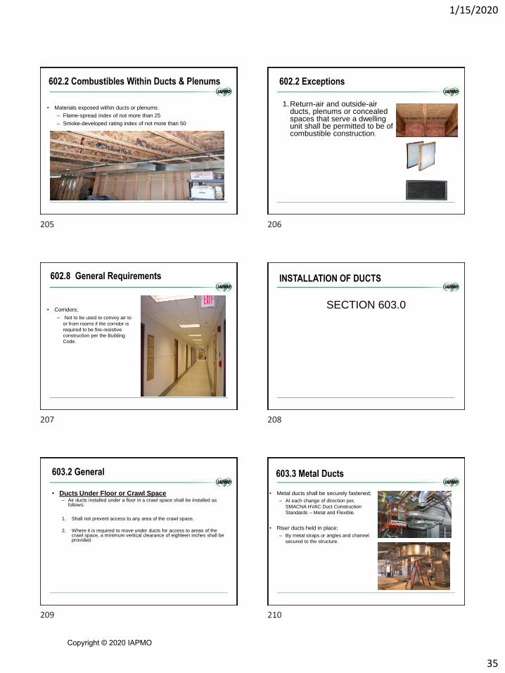
602.2 Combustibles Within Ducts & Plenums
• Materials exposed within ducts or plenums:
– Flame-spread index of not more than 25
– Smoke-developed rating index of not more than 50
602.2 Exceptions
1.Return-air and outside-air ducts, plenums or concealed spaces that serve a dwelling unit shall be permitted to be of combustible construction.
602.8 General Requirements
• Corridors;
– Not to be used to convey air to
or from rooms if the corridor is
required to be fire-resistive
construction per the Building
Code.
INSTALLATION OF DUCTS
SECTION 603.0
603.2 General
• Ducts Under Floor or Crawl Space– Air ducts installed under a floor in a crawl space shall be installed as
follows:
1. Shall not prevent access to any area of the crawl space.
2. Where it is required to move under ducts for access to areas of the crawl space, a minimum vertical clearance of eighteen inches shall be provided.
603.3 Metal Ducts
• Metal ducts shall be securely fastened;
– At each change of direction per,
SMACNA HVAC Duct Construction
Standards – Metal and Flexible.
• Riser ducts held in place;
– By metal straps or angles and channel
secured to the structure.
205 206
207 208
209 210
Copyright © 2020 IAPMO
1/15/2020
36
603.3 Metal Ducts
• 4" separation from earth.
• Install in buildings with clearance for full thickness of fireproofing on structural members.
603.3 Horizontal Round Metal Duct
• 603.2.3 Each circular
band shall be provided
with a means of
connecting to the
suspending support.
• 603.3.3 Ducts located in
seismic zones C-F shall
be in accordance with the
building code.
603.4 Factory - Made Flexible Air Ducts and
Connectors
• Shall not be used for vertical risers in air-duct systems serving more than two stories
• Shall not penetrate a fire-resistance-rated assembly or construction.
• Shall be installed with not less than 4 inches of separation from earth
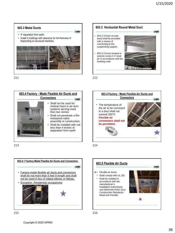
603.4 Factory - Made Flexible Air Ducts and
Connectors
• The temperature of
the air to be conveyed
in a duct shall not
exceed 250°F.
Flexible air
connectors shall not
be permitted.
603.4.1 Factory-Made Flexible Air Ducts and Connectors.
• Factory-made flexible air ducts and connectors
shall be not more than 5 feet in length and shall
not be used in lieu of ridged elbows or fittings.
• Exception. Residential occupancies
603.5 Flexible Air Ducts
• Flexible air ducts:
• Shall comply with UL 181
• Shall be installed in
accordance with the
manufacturer’s
installation instructions,
and SMACNA HVAC Duct
Construction Standards -
Metal and Flexible.
211 212
213 214
215 216
Copyright © 2020 IAPMO
1/15/2020
37
603.5 Flexible Air Ducts
• (1) Ducts shall be installed using the minimum
required length to make the connection.
• (2) Horizontal duct runs shall be supported at
not more than 4 feet intervals.
• (3) Vertical risers shall be supported at not more
than 6 feet intervals
603.5 Flexible Air Ducts
• (4) Sag between support hangers shall not
exceed 1⁄2 inch per foot of support spacing.
• (5) Supports shall be rigid and shall be not less
than 11⁄2 inches wide at point of contact with
the duct surface.
• (6) Duct bends shall be not less than one duct
diameter bend radius.
603.5 Flexible Air Ducts
• (7) Screws shall not penetrate the inner liner of
non-metallic flexible ducts unless permitted
in accordance with the manufacturer’s
installation instructions.
• (8) Fittings for attaching non-metallic ducts shall
be beaded and have a collar length of not
less than 2 inches for attaching the duct.
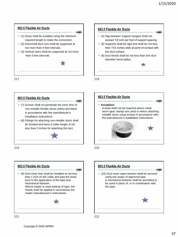
603.5 Flexible Air Ducts
• Exception:
A bead shall not be required where metal
worm-gear clamps are used or where attaching
metallic ducts using screws in accordance with
the manufacturer’s installation instructions.
603.5 Flexible Air Ducts
• (9) Duct inner liner shall be installed at not less
than 1 inch on the collar and past the bead
prior to the application of the tape and
mechanical fastener.
Where mastic is used instead of tape, the
mastic shall be applied in accordance the
mastic manufacturer’s instructions.
603.5 Flexible Air Ducts
• (10) Duct outer vapor barriers shall be secured
using two wraps of approved tape.
A mechanical fastener shall be permitted to
be used in place of, or in combination with,
the tape.
217 218
219 220
221 222
Copyright © 2020 IAPMO
1/15/2020
38
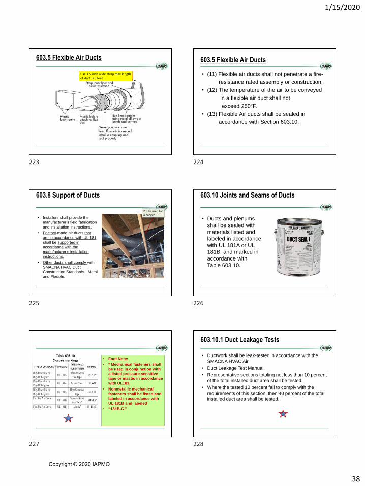
603.5 Flexible Air Ducts
Use 1.5 inch wide strap max length of duct is 5 feet
603.5 Flexible Air Ducts
• (11) Flexible air ducts shall not penetrate a fire-
resistance rated assembly or construction.
• (12) The temperature of the air to be conveyed
in a flexible air duct shall not
exceed 250°F.
• (13) Flexible Air ducts shall be sealed in
accordance with Section 603.10.
603.8 Support of Ducts
• Installers shall provide the
manufacturer’s field fabrication
and installation instructions.
• Factory-made air ducts that
are in accordance with UL 181
shall be supported in
accordance with the
manufacturer’s installation
instructions.
• Other ducts shall comply with
SMACNA HVAC Duct
Construction Standards - Metal
and Flexible.
Zip tie used for a hanger
603.10 Joints and Seams of Ducts
• Ducts and plenums
shall be sealed with
materials listed and
labeled in accordance
with UL 181A or UL
181B, and marked in
accordance with
Table 603.10.
• Foot Note:
• * Mechanical fasteners shall
be used in conjunction with
a listed pressure sensitive
tape or mastic in accordance
with UL181.
• Nonmetallic mechanical
fasteners shall be listed and
labeled in accordance with
UL 181B and labeled
• “181B-C.”
Table 603.10 Closure markings
603.10.1 Duct Leakage Tests
• Ductwork shall be leak-tested in accordance with the
SMACNA HVAC Air
• Duct Leakage Test Manual.
• Representative sections totaling not less than 10 percent
of the total installed duct area shall be tested.
• Where the tested 10 percent fail to comply with the
requirements of this section, then 40 percent of the total
installed duct area shall be tested.
223 224
225 226
227 228
Copyright © 2020 IAPMO

1/15/2020
39
603.10.1 Duct Leakage Tests
• Where the tested 40 percent fail to comply with the
requirements of this section, then 100 percent of the total
installed duct area shall be tested.
• Sections shall be selected by the building owner or
designated representative of the building owner.
• Positive pressure leakage testing shall be permitted for
negative pressure ductwork.
603.11 Cross Contamination
• Exhaust ducts and venting systems under
positive pressure shall not extend into or pass
through ducts and plenums.
603.12 Underground Installation
• Ducts installed
underground shall be
approved for the
installation and shall have
a slope of not less 1⁄8
inch per foot (10.4
mm/m).
Consolidation of requirements.
603.12 Underground Installation
• Ducts, plenums, and fittings shall be permitted to be
constructed of concrete, clay, or ceramics where
installed in the ground or in a concrete slab, provided the
joints are tightly sealed.
• Metal ducts where installed in or under a concrete slab
shall be encased in not less than 2 inches of concrete.
Figure 603.8
603.13 Air Dispersion Systems
• Where installed, air dispersion systems shall be completely in exposed locations in duct systems under positive pressure, and not pass through or penetrate fire-resistant-rated construction.
• Air dispersion systems shall be listed and labeled in accordance with UL 2518.
229 230
231 232
233 234
Copyright © 2020 IAPMO

1/15/2020
40
2018 IMC
Chapter 8 –
Chimneys and Vents
805.7 Insulation shield
• Where factory-built chimneys pass through
insulated assemblies, an insulation shield
constructed of steel having a thickness of not
less than 0.0187 inch (No. 26 gage) shall be
installed to provide clearance between the
chimney and the insulation material.
805.7 Insulation shield
• The clearance shall be
not less than the
clearance to
combustibles specified
by the chimney
manufacturer’s
installation instructions.
805.7 Insulation shield
• Where chimneys pass through attic space, the shield
shall terminate not less than 2 inches above the
insulation materials and shall be secured in place to
prevent displacement.
805.7 Insulation shield
• Insulation shields provided as part of a listed
chimney system shall be installed in accordance
with the manufacturer’s instructions.
CHAPTER 9INSTALLATION OF SPECIFIC
APPLIANCES
235 236
237 238
239 240
Copyright © 2020 IAPMO

1/15/2020
41
2018 IMC
CHAPTER 9
SPECIFIC APPLIANCES, FIREPLACES AND SOLID FUEL-BURNING EQUIPMENT
901.4 Solid fuel-burning fireplaces and appliances in
Group I-2, Condition 2.
• In Group I-2, Condition 2 occupancies,
solid fuel-burning fireplaces and
appliances are prohibited.
POOL AND SPA HEATERS
• 916.1 General
• Pool and spa heat pump water heaters shall comply with UL 1995 or
CSA C22.2 No. 236.
Exception:
Portable residential spas and portable
residential exercise spas shall comply with UL
1563 or CSA C22.2 No. 218.1.
HIGH-VOLUME LARGE-DIAMETER FANS
• 929.1 General
• Where provided, high-volume large-diameter fans shall be tested
and labeled in accordance with AMCA 230, listed and labeled in
accordance with UL 507, and installed in accordance with the
manufacturer’s instructions.
2018 UMC
CHAPTER 9
SPECIFIC APPLIANCES, FIREPLACES AND SOLID FUEL-BURNING EQUIPMENT
902.2 Combustion Air from Bedroom or
Bathroom
• Appliances shall not be
installed so their
combustion, ventilation,
and dilution air are
obtained only from a
bedroom or bathroom
unless the bedroom or
bathroom has the
required volume in
accordance with Section
701.4. [NFPA 54:10.1.2]
241 242
243 244
245 246
Copyright © 2020 IAPMO
1/15/2020
42
902.3 Added or Converted Appliances
• When additional or replacement appliances or
equipment is installed or an appliance is converted to
gas from another fuel, the location in which the
appliances or equipment is to be operated shall be
checked to verify the following:
(1) Air for combustion and ventilation is provided where required,
in accordance with the provisions of Section 701.0.
Where existing facilities are not adequate, they shall be
upgraded to meet Section 701.0 specifications.
902.3 Added or Converted Appliances
(2) The installation components and appliances meet the clearances to
combustible material provisions of Section 303.10.
It shall be determined that the installation and operation of the
additional or replacement appliances do not render the remaining
appliances unsafe for continued operation.
(3) The venting system is constructed and sized in accordance
with the provisions of Section 802.0.
Where the existing venting system is not adequate, it shall be
upgraded to comply with Section 802.0. [NFPA 54:9.1.2]
902.7 Use of Air or Oxygen Under Pressure
• Where air or oxygen under pressure is used in
connection with the gas supply, effective means such as
a back pressure regulator and relief valve shall be
provided to prevent air or oxygen from passing back into
the gas piping.
• Where oxygen is used, installation shall be in
accordance with NFPA 51. [NFPA 54:9.1.5]
902.8.1 Structural Capacity
• At the locations selected for installation of appliances
and equipment, the dynamic and static load-carrying
capacities of the building structure shall be checked to
determine whether they are adequate to carry the
additional loads.
902.14 Gas Appliance Pressure Regulators
• Where the gas supply pressure is higher than that at
which the appliance is designed to operate or varies
beyond the design pressure limits of the appliance, a gas
appliance pressure regulator shall be installed. [NFPA
54:9.1.18]
902.15 Venting of Gas Appliance Pressure
Regulators
• Venting of gas appliance pressure regulators shall
comply with the following requirements:(1) Appliance pressure regulators requiring access to the atmosphere for
successful operation shall be equipped with vent piping leading outdoors
or, if the regulator vent is an integral part of the appliance, into the
combustion chamber adjacent to a continuous pilot, unless constructed
or equipped with a vent limiting means to limit the escape of gas from
the vent opening in the event of diaphragm failure.
247 248
249 250
251 252
Copyright © 2020 IAPMO

1/15/2020
43
902.15 Venting of Gas Appliance Pressure
Regulators
(2) Vent limiting means shall be employed on listed appliance pressure
regulators only.
(5) In the case of vents entering the combustion chamber, the vent shall be
located so the escaping gas is readily ignited by the pilot and the heat
liberated thereby does not adversely affect the normal operation of the
safety shutoff system.
The terminus of the vent shall be securely held in a fixed position
relative to the pilot.
For manufactured gas, the need for a flame arrester in the vent piping
shall be determined.
902.15 Venting of Gas Appliance Pressure
Regulators
(6) A vent line(s) from an appliance pressure regulator
and a bleed line(s) from a diaphragm-type valve shall
not be connected to a common manifold terminating
in a combustion chamber.
Vent lines shall not terminate in positive pressure-
type combustion chambers. [NFPA 54:9.1.19]
904.5 Low-Water Cutoff
• In lieu of the low-water cutoff, water tube or coil-type boilers that require forced circulation to prevent overheating and failure
• shall have an approved flow sensing device arranged to shut down the boiler where the flow rate is not capable of protecting the boiler against overheating.
Revised to correlate with NFPA 54-2012
CHAPTER 10 UMCBOILERS AND PRESSURE
VESSELS
1002.5 Dual Purpose Water Heater
• Water heaters utilized for combined space- and water-heating applications shall be listed or labeled in accordance with the standards referencedin Table 1203.2, and shall be installed in accordance with the manufacturer’s installation instructions.
Check the label
1003.3 Gauges
• Steam boilers shall be
provided with a
pressure gauge and a
water level glass
253 254
255 256
257 258
Copyright © 2020 IAPMO

1/15/2020
44
CHAPTER 10 2018 IMC
BOILERS, WATER HEATERS AND
PRESSURE VESSELS
WATER HEATERS
• Solid-fuel fired water heaters shall comply with UL 2523.
• Solar thermal water heating systems shall comply with Chapter 14
and ICC 900/SRCC 300.
1006.6 Safety and relief valve discharge
• The discharge piping serving pressure
relief valves, temperature relief valves and
combinations of such valves shall:1. Not be directly connected to the
drainage system.
2. Discharge through an air break
located in the same room as the
appliance.
1006.6 Safety and relief valve discharge
3. Not be smaller than the diameter of the
outlet of the valve served and shall
discharge full size to the air break.4. Serve a single relief device and shall not
connect to piping serving any other relief
device or equipment.
5. Discharge to the floor, to the pan serving the
boiler or storage tank, to a waste receptor or
to the outdoors.
1006.6 Safety and relief valve discharge
6. Discharge in a manner that does not cause
personal injury or structural damage
7. Discharge to a termination point that is readily
observable by the building occupants.
8. Not be trapped.
9. Be installed so as to flow by gravity.
10. Not terminate more than 6 inches above the
floor or waste receptor.
1006.6 Safety and relief valve discharge
11. Not have a threaded connection at the end
of such piping.
12. Not have valves or tee fittings.
13. Be constructed of those materials listed in
Section 605.4 of the International Plumbing
Code or materials tested, rated and approved
for such use in accordance with ASME
A112.4.1.
259 260
261 262
263 264
Copyright © 2020 IAPMO

1/15/2020
45
HOT WATER BOILER EXPANSION TANK
• 1009.1 Where requiredException:
Expansion tanks shall not be required in the
collector loop of drain-back systems.
CHAPTER 11 IMC
REFRIGERATION
1101.6 General
• Refrigeration systems shall comply with the requirements of this
code and, except as modified by this code, ASHRAE 15.
• Ammonia-refrigerating systems shall comply with this code and,
except as modified by this code,
• ASHRAE 15, IIAR 2, IIAR 3, IIAR 4 and IIAR 5.
1104.2.2 Industrial occupancies and refrigerated rooms
• This section applies only to rooms and spaces that:
A. Are within industrial occupancies;
B. Contain a refrigerant evaporator;
C. Are maintained at temperatures below 68°F
D. Are used for manufacturing, food and
beverage preparation, meat cutting, other
processes and storage.
Where a machinery room would otherwise
be required by Section 1104.2, a machinery
room shall not be required where all of the
following conditions are met:
265 266
267 268
269 270
Copyright © 2020 IAPMO

1/15/2020
46
1104.2.2 Industrial occupancies and refrigerated rooms
1. The space containing the
machinery is separated
from other occupancies
by tight construction
with tight-fitting doors.
2. Access is restricted to
authorized personnel.
1104.2.2 Industrial occupancies and refrigerated rooms
3. Refrigerant detectors are installed as required
for machinery rooms in accordance with
Section 1105.3.
• Exceptions:
1. Refrigerant detectors are not required in
unoccupied areas that contain only continuous
piping that does not include valves, valve
assemblies, equipment, or equipment
connections.
What about the roof?
1104.2.2 Industrial occupancies and refrigerated rooms
2. Where approved alternatives are provided,
refrigerant detectors for ammonia
refrigeration are not required for rooms or
areas that are always occupied, and for
rooms or areas that have high humidity or
other harsh environmental conditions that are
incompatible with detection devices.
1104.2.2 Industrial occupancies and refrigerated
rooms
4. Surfaces having temperatures exceeding
800°F and open flames are not present where
any Group A2, B2, A3 or B3 refrigerant is used
(see Section 1104.3.4).
1104.2.2 Industrial occupancies and refrigerated rooms
5. All electrical equipment and appliances
conform to Class 1, Division 2, hazardous
location classification requirements of NFPA
70 where the quantity of any Group A2, B2,
A3 or B3 refrigerant, other than ammonia, in a
single independent circuit would exceed 25
percent of the lower flammability limit (LFL)
upon release to the space.
1104.2.2 Industrial occupancies and refrigerated rooms
6. All refrigerant-containing parts in systems with
a total connected compressor power
exceeding 100 horsepower except
evaporators used for refrigeration or
dehumidification, condensers used for
heating, control and pressure relief
valves for either, low-probability pumps and
connecting piping—are located either
outdoors or in a machinery room.
271 272
273 274
275 276
Copyright © 2020 IAPMO
1/15/2020
47
MACHINERY ROOM, GENERAL REQUIREMENTS
1105.6.1.1 Indoor exhaust opening location
• Indoor mechanical exhaust intake openings shall be located where
refrigerant leakage is likely to concentrate based on the refrigerant’s
relative density to air, and the locations of the air current paths and
refrigerating machinery.
MACHINERY ROOM, SPECIAL
REQUIREMENTS
SECTION 11061106.4 Flammable refrigerants
• Where refrigerants of Groups A2, A3, B2 and B3 are used, the
machinery room shall conform to the Class 1, Division 2, hazardous
location classification requirements of NFPA 70.
• Exceptions:
2. Machinery rooms for systems containing
Group A2L refrigerants that are in
accordance with Section 1106.5.
1106.5 Special requirements for Group A2L refrigerant
machinery rooms
• Machinery rooms for systems containing Group A2L refrigerants
shall comply with Sections 1106.5.1 through 1106.5.3.
• Exception:
Machinery rooms conforming to the Class I,
Division 2, hazardous location classification
requirements of NFPA 70 are not required to
comply with Sections 1106.5.1 and 1106.5.2.
1106.5.1 Refrigerant detection system
• The machinery room shall be provided with a refrigerant detection
system.
• The refrigerant detection system shall be in accordance with Section
605.8 of the International Fire Code and all of the following:
1. The detectors shall activate at or below a
refrigerant concentration of 25% of the LFL.
277 278
279 280
281 282
Copyright © 2020 IAPMO

1/15/2020
48
1106.5.2 Emergency ventilation system
• An emergency ventilation system shall be provided at the minimum
exhaust rate specified in ASHRAE 15 or Table 1106.5.2.
• Shutdown of the emergency ventilation system shall be by manual
means.
New Table
1107.2 Piping location
• Refrigerant piping shall not be placed in any of the following:
1. A fire-resistance-rated exit access corridor.
2. An interior exit stairway.
3. An interior exit ramp.
4. An exit passageway.
5. An elevator, dumbwaiter or other shaft
containing a moving object.
6. A shaft that has one or more openings into a
fire-resistance-rated exit access corridor,
interior exit stairway or ramp or exit
passageway.
1107.5.2 Copper and copper-alloy pipe
• Standard iron pipe size, copper and copper-alloy (not less than 80-
percent copper) pipe shall conform to ASTM B42 and ASTM B43.
1107.5.3 Copper tube
• Copper tube used for refrigerant piping erected on the premises
shall be seamless copper tube of Type ACR (hard or annealed)
complying with ASTM B280 or ASTM B819.
• Annealed temper copper tube shall not be used in sizes larger than
a 2-inch nominal size.
• Mechanical joints other than press-connect joints listed for
refrigerant piping shall not be used on annealed temper copper tube
in sizes larger than 7/8-inch OD size.
CHAPTER 11 UMC
REFRIGERATION
283 284
285 286
287 288
Copyright © 2020 IAPMO

1/15/2020
49
1101.6 General
• Refrigeration systems using a refrigerant other than
ammonia shall comply with this chapter and ASHRAE
15.
1102.2 Ammonia Refrigeration Systems
• Refrigeration systems using ammonia as the refrigerant
shall comply with IIAR 2, IIAR 3, IIAR 4, and IIAR 5 and
shall not be required to comply with this chapter.
1103.1 Classification of Refrigerants
• Refrigerants shall be classified in accordance with Table
1102.3 or in accordance with ASHRAE 34 where
approved by the Authority Having Jurisdiction
1104.5 Flammable Refrigerants
• The total of Group A2, B2, A3, and B3
refrigerants, other than Group A2L and B2L
refrigerants shall not exceed 1100 pounds
without approval by the Authority Having
Jurisdiction.
• Institutional Occupancies shall comply with
Section 1104.3.
MACHINERY ROOM, SPECIAL
REQUIREMENTS
SECTION 1106.2
Machinery Room Requirements [ASHRAE 15]
• 1106.2.1 Access
• It is ok to have other mechanical equipment in the
Machinery room unless specifically prohibited elsewhere
in this chapter.
289 290
291 292
293 294
Copyright © 2020 IAPMO
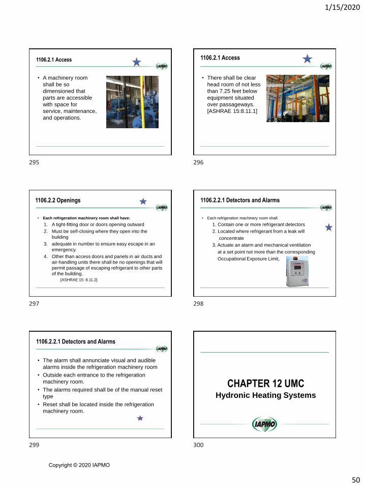
1/15/2020
50
1106.2.1 Access
• A machinery room
shall be so
dimensioned that
parts are accessible
with space for
service, maintenance,
and operations.
1106.2.1 Access
• There shall be clear
head room of not less
than 7.25 feet below
equipment situated
over passageways.
[ASHRAE 15:8.11.1]
1106.2.2 Openings
• Each refrigeration machinery room shall have:
1. A tight-fitting door or doors opening outward
2. Must be self-closing where they open into the
building
3. adequate in number to ensure easy escape in an
emergency.
4. Other than access doors and panels in air ducts and
air-handling units there shall be no openings that will
permit passage of escaping refrigerant to other parts
of the building.
[ASHRAE 15: 8.11.2]
1106.2.2.1 Detectors and Alarms
• Each refrigeration machinery room shall:
1. Contain one or more refrigerant detectors
2. Located where refrigerant from a leak will
concentrate
3. Actuate an alarm and mechanical ventilation
at a set point not more than the corresponding
Occupational Exposure Limit,
1106.2.2.1 Detectors and Alarms
• The alarm shall annunciate visual and audible
alarms inside the refrigeration machinery room
• Outside each entrance to the refrigeration
machinery room.
• The alarms required shall be of the manual reset
type
• Reset shall be located inside the refrigeration
machinery room.
CHAPTER 12 UMCHydronic Heating Systems
295 296
297 298
299 300
Copyright © 2020 IAPMO
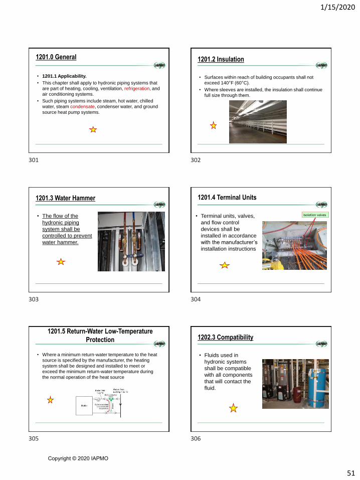
1/15/2020
51
1201.0 General
• 1201.1 Applicability.
• This chapter shall apply to hydronic piping systems that
are part of heating, cooling, ventilation, refrigeration, and
air conditioning systems.
• Such piping systems include steam, hot water, chilled
water, steam condensate, condenser water, and ground
source heat pump systems.
1201.2 Insulation
• Surfaces within reach of building occupants shall not
exceed 140°F (60°C).
• Where sleeves are installed, the insulation shall continue
full size through them.
1201.3 Water Hammer
• The flow of the
hydronic piping
system shall be
controlled to prevent
water hammer.
1201.4 Terminal Units
• Terminal units, valves,
and flow control
devices shall be
installed in accordance
with the manufacturer’s
installation instructions
Isolation valves
• Where a minimum return-water temperature to the heat
source is specified by the manufacturer, the heating
system shall be designed and installed to meet or
exceed the minimum return-water temperature during
the normal operation of the heat source
1201.5 Return-Water Low-Temperature
Protection 1202.3 Compatibility
• Fluids used in
hydronic systems
shall be compatible
with all components
that will contact the
fluid.
301 302
303 304
305 306
Copyright © 2020 IAPMO

1/15/2020
52
1203.3 Tankless Water Heater
• Tankless water heaters shall be rated by the manufacturer for space- heating applications, and the output performance shall be determined by the temperature rise and flow rate of water through the unit.
1205.2 Pressure Testing
• Exception:
• For PEX, PP-R, PP-RCT, PEX-AL-PEX, PE-RT, and PE-AL-PE piping systems, testing with air shall be permitted where authorized by the manufacturer’s instructions for the PEX, PP-R, PP-RCT, PEX-AL-PEX, PE-RT, and PE-ALPE pipe and fittings products, and air testing is not prohibited by applicable codes, laws, or regulations outside this code.
1205.3 Flushing
• Heating and cooling sources, system piping and tubing shall be flushed after installation with water or a cleaning solution.
• Cleaning and flushing of the heating and cooling sources shall comply with the manufacturer’s instructions.
• The cleaning solution shall be compatible with all system components and shall be used in accordance with the manufacturer’s instructions.
1206.0 Safety Devices 1206.1 General.
• Each closed hydronic
system shall be protected
against pressures
exceeding design
limitations with not less
than one pressure relief
valve.
1206.0 Safety Devices
• Each closed section of the system containing a heat
source shall have a relief valve located so that the heat
source is not capable of being isolated from a relief
device.
Relief valve on solar unit
Water heater relief valve
Pressure relief valves shall be installed in accordance with their listing and the manufacturer’s installation instructions
1207.3. Dual-Purpose Water Heaters
• Water used as the heat transfer fluid in the hydronic
heating system shall be isolated from the potable water
supply and distribution in accordance with Section 312.1,
Section 1202.0, and Section 1218.0.
307 308
309 310
311 312
Copyright © 2020 IAPMO

1/15/2020
53
1208.0 Circulators
• 1208.1 General.
• Circulators and pumps shall be
selected for their intended use
based on the heat transfer fluid,
intended operating temperature
range and pressure.
• Circulators and pumps shall be
installed to allow for service and
maintenance
1209.0 Expansion Tanks
• An expansion tank shall be installed in each closed
hydronic system to control system pressure due to
thermal expansion.
• Expansion tanks shall be of the closed or open type.
• Tanks shall be rated for the pressure of the system.
All hydronic systems must account for the thermal expansion of the heating fluid
1209.2 Installation
• Expansion tanks shall be accessible for maintenance
and shall be installed in accordance with the
manufacturer’s installation instructions.
• Each tank shall be equipped with a shutoff device that
will remain open during operation of the heating system.
1209.2 Installation
• Valve handles shall be locked open or removed to
prevent from being inadvertently shut off.
• Provisions shall be made for draining the tank without
emptying the system.
• Expansion tanks shall be securely fastened to the
structure.
1209.2 Installation
• Supports shall be capable of carrying twice the weight of
the tank filled with water without placing a strain on
connecting piping.
• Hot-water-heating systems incorporating hot water
tanks or fluid relief columns shall be installed to
prevent freezing under normal operating conditions.
1209.3 Open-Type Expansion Tanks
• Open type expansion tanks shall be located not less
than 3 feet above the highest point of the system.
• An overflow with a diameter of not less than one-half the
size of the supply or not less than 1 inch in diameter
shall be installed at the top of the tank.
• The overflow shall discharge through an air gap into the
drainage system.
313 314
315 316
317 318
Copyright © 2020 IAPMO

1/15/2020
54
1209.4 Closed-Type Tanks
• Closed-type expansion tanks shall
be designed for a hydrostatic test
pressure of two and one-half times
the allowable working pressure of
the system
• Expansion tanks for systems
designed to operate at more than 30
pounds-force per square inch (psi)
shall comply with ASME BPVC
Section VIII
1209.5 Sizing
• Expansion tanks shall be
sized to accept the full
expansion volume of the
fluid in the system.
• The minimum capacity of a
closed-type expansion tank
shall be sized in
accordance with Section
1004.4
1210.1 Piping, Tubing, and Fittings
• Pipe fittings and valves shall be
approved for the specific
installation with the piping,
materials to be installed and
shall comply with the applicable
standards referenced in Table
1210.1.
• Where required, exterior piping
shall be protected against
freezing, UV radiation, corrosion
and degradation.
1210.3 Hangers and Supports
• Equipment that is part
of the piping system
shall be provided with
additional support in
accordance with this
code and
manufacturer’s
installation
instructions.
1210.4 Oxygen Diffusion Corrosion
• PEX and PE-RT tubing
in closed hydronic
systems shall contain an
oxygen barrier.
• Exception: Closed
hydronic systems
without ferrous
components in contact
with the hydronic fluid.
1211.0 Joints and Connections
• 1211.1 General.
• Pipe bends shall have a radius of not less than six times
the outside diameter of the tubing or shall be in
accordance with the manufacturer’s installation
instructions.
• Joints between pipe and fittings shall be installed in
accordance with the manufacturer’s installation
instructions.
319 320
321 322
323 324
Copyright © 2020 IAPMO
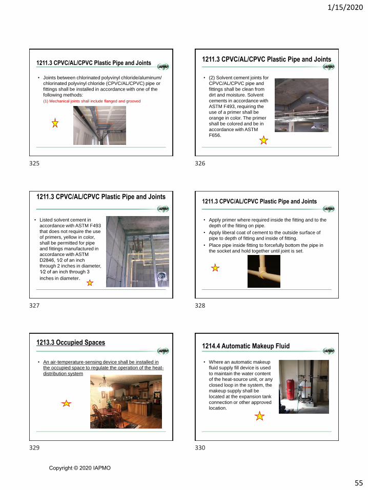
1/15/2020
55
1211.3 CPVC/AL/CPVC Plastic Pipe and Joints
• Joints between chlorinated polyvinyl chloride/aluminum/
chlorinated polyvinyl chloride (CPVC/AL/CPVC) pipe or
fittings shall be installed in accordance with one of the
following methods:
(1) Mechanical joints shall include flanged and grooved
1211.3 CPVC/AL/CPVC Plastic Pipe and Joints
• (2) Solvent cement joints for
CPVC/AL/CPVC pipe and
fittings shall be clean from
dirt and moisture. Solvent
cements in accordance with
ASTM F493, requiring the
use of a primer shall be
orange in color. The primer
shall be colored and be in
accordance with ASTM
F656.
1211.3 CPVC/AL/CPVC Plastic Pipe and Joints
• Listed solvent cement in
accordance with ASTM F493
that does not require the use
of primers, yellow in color,
shall be permitted for pipe
and fittings manufactured in
accordance with ASTM
D2846, 1⁄2 of an inch
through 2 inches in diameter,
1⁄2 of an inch through 3
inches in diameter.
1211.3 CPVC/AL/CPVC Plastic Pipe and Joints
• Apply primer where required inside the fitting and to the
depth of the fitting on pipe.
• Apply liberal coat of cement to the outside surface of
pipe to depth of fitting and inside of fitting.
• Place pipe inside fitting to forcefully bottom the pipe in
the socket and hold together until joint is set.
1213.3 Occupied Spaces
• An air-temperature-sensing device shall be installed in
the occupied space to regulate the operation of the heat-
distribution system
1214.4 Automatic Makeup Fluid
• Where an automatic makeup
fluid supply fill device is used
to maintain the water content
of the heat-source unit, or any
closed loop in the system, the
makeup supply shall be
located at the expansion tank
connection or other approved
location.
325 326
327 328
329 330
Copyright © 2020 IAPMO

1/15/2020
56
1214.4 Automatic Makeup Fluid
• A pressure-reducing valve shall be installed on a
makeup water feed line.
• The pressure of the feed line shall be set in accordance
with the design of the system, and connections to
potable water shall be in accordance with Section 1202.0
to prevent contamination due to backflow
1214.6 Air-Removal Device
• Provision shall be made for
the removal of air in the heat-
distribution piping system.
• The air-removal device shall
be located in the area of the
hydronic piping system where
air is likely to accumulate. Air-
removal devices shall be
installed to facilitate their
removal for examination,
repair, or replacement.
1214.8 Secondary Loops
• Secondary loops that are isolated from the primary heat-distribution loop by a heat exchanger are closed-loop hydronic systems and shall have an expansion tank in accordance with Section 1209.0, an air removal device in accordance with Section 1214.6, and an air-separation device in accordance with Section 1214.7.
1215.3 Freeze Protection
• Hydronic systems and
components shall be
designed, installed,
and protected from
freezing.
1215.5 Heat Transfer Fluid
• The ignitable flash point of heat transfer fluid in a hydronic piping system shall be a minimum of 50°F above the maximum system operating temperature.
• The heat transfer fluid shall be compatible with the makeup fluid supplied to the system.
1216.2 Sloping for Two-Pipe System
• Two-pipe steam
system piping and
heat-distribution units
shall be sloped down
at not less than 1/8
inch per foot in the
direction of the steam
flow.
331 332
333 334
335 336
Copyright © 2020 IAPMO

1/15/2020
57
1216.3 Sloping for One-Pipe System
• One-pipe steam
system piping and
heat-distribution units
shall be sloped down
at not less than 1/8
inch per foot towards
the steam boiler,
without trapping.
1216.4 Automatic Air Vents
• Steam automatic air
vents shall be
installed to eliminate
air pressure in heat-
distribution units on
gravity steam piping
systems.
• Air vents shall not be
used on a vacuum
system.
1216.5 Condensate Flow
• System piping shall
be installed to allow
condensate to flow to
the condensate
receiver orsteam
boiler either by gravity
or pump-assisted
1217.0 Radiant Heating and Cooling
1217.1 Installation
• Radiant heating and cooling systems shall be
installed in accordance with the system design.
1217.1.1 Manifolds
• Manifolds shall be equipped with isolation valves
on the supply and return lines
337 338
339 340
341 342
Copyright © 2020 IAPMO
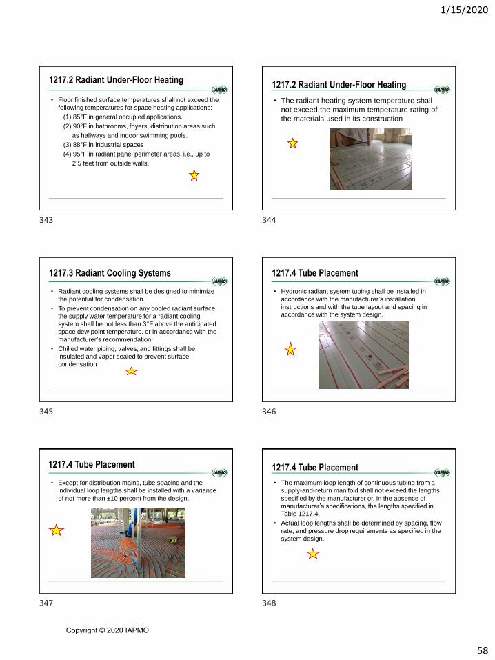
1/15/2020
58
1217.2 Radiant Under-Floor Heating
• Floor finished surface temperatures shall not exceed the
following temperatures for space heating applications:
(1) 85°F in general occupied applications.
(2) 90°F in bathrooms, foyers, distribution areas such
as hallways and indoor swimming pools.
(3) 88°F in industrial spaces
(4) 95°F in radiant panel perimeter areas, i.e., up to
2.5 feet from outside walls.
1217.2 Radiant Under-Floor Heating
• The radiant heating system temperature shall
not exceed the maximum temperature rating of
the materials used in its construction
1217.3 Radiant Cooling Systems
• Radiant cooling systems shall be designed to minimize
the potential for condensation.
• To prevent condensation on any cooled radiant surface,
the supply water temperature for a radiant cooling
system shall be not less than 3°F above the anticipated
space dew point temperature, or in accordance with the
manufacturer’s recommendation.
• Chilled water piping, valves, and fittings shall be
insulated and vapor sealed to prevent surface
condensation
1217.4 Tube Placement
• Hydronic radiant system tubing shall be installed in
accordance with the manufacturer’s installation
instructions and with the tube layout and spacing in
accordance with the system design.
1217.4 Tube Placement
• Except for distribution mains, tube spacing and the
individual loop lengths shall be installed with a variance
of not more than ±10 percent from the design.
1217.4 Tube Placement
• The maximum loop length of continuous tubing from a
supply-and-return manifold shall not exceed the lengths
specified by the manufacturer or, in the absence of
manufacturer’s specifications, the lengths specified in
Table 1217.4.
• Actual loop lengths shall be determined by spacing, flow
rate, and pressure drop requirements as specified in the
system design.
343 344
345 346
347 348
Copyright © 2020 IAPMO

1/15/2020
59
1217.5 Poured Floor Structural Concrete Slab
Systems (Thermal Mass).
• Where tubing is embedded in a structural concrete slab
such tubes shall not be larger in outside dimension than
one-third of the overall thickness of the slab and shall be
spaced not less than three diameters on center except
within 10 feet of the distribution manifold.
• The top of the tubing shall be embedded in the slab not
less than 2 inches below the surface.
1217.5.1 Slab Penetration Tube and Joint
Protection
• Where embedded in or installed under a concrete slab,
tubing shall be protected from damage at penetrations of
the slab with protective sleeving approved by the tubing
manufacturer.
1217.5.1 Slab Penetration Tube and Joint Protection
• The space between the tubing and sleeve shall be
sealed with an approved sealant compatible with the
tubing.
• The tubing at the location of an expansion joint in a concrete slab
shall be encased in protective pipe sleeving that covers the tubing
not less than 12 inches on either side of the expansion joint or the
tubing shall be installed below the slab.
1217.5.2 Insulation
• Where a poured concrete radiant floor system is installed in contact with the soil, insulation approved for such an application with a minimum R-value of 5 shall be placed between the soil and the concrete; extend to the outside edges of the concrete; and be placed on all slab edges.
1217.5.3 Joist Systems and Subfloors
• Where tubing is
installed in the joist
cavity, the cavity shall
be insulated with not
less than R-12
material below the
heated space
1217.5.3 Joist Systems and Subfloors
• An air space of not less than 1 inch and not more than 3 inches shall be maintained between the top of the insulation and the underside of the floor unless a conductive plate is installed in accordance with manufacturer’s instructions
349 350
351 352
353 354
Copyright © 2020 IAPMO

1/15/2020
60
1217.5.3 Joist Systems and Subfloors
• Where tubing is
installed in panels
above or in the subfloor
and not embedded in
concrete, the floor
assembly shall be
insulated with not less
than R-5 material below
the tubing when
installed over habitable
space
1217.5.4 Wall and Ceiling Panels
• An air space of not less than 1 inch and not more than 3
inches shall be maintained between the insulation and
the interior surface of the panel unless a conductive
plate is installed.
1217.6.2 Radiant Wall and Ceiling Panels
• Radiant panels attached to wood, steel, masonry, or
concrete framing members shall be fastened by means
of anchors, bolts, or approved screws of sufficient size
and anchorage to support the loads applied
1220.2 Snow and Ice Melt Controls
• An automatic thermostatically operating control device
that controls the supply hydronic solution temperature to
the snow and ice melt area shall be installed in the
system.
• Snow and ice melt systems shall be protected from
freezing with a mixture of propylene glycol or ethylene
glycol, and water or other approved fluid.
• Automotive antifreeze shall not be used.
Duplication of requirements
• 1220.2.1 Tube Placement
• 1220.2.2 Poured Concrete Slab Systems (Thermal Mass).
• 1220.2.3 Slab Penetration Tube and Joint Protection.
• 1220.2.6 Testing and Flushing
355 356
357 358
359 360
Copyright © 2020 IAPMO

1/15/2020
61
1220.3 Hydronic Makeup Air Units
• Hydronic makeup air units that are affected by
freezing shall be protected against freezing by a
hydronic solution.
1221.2 Embedded Piping Materials and Joints
• Piping embedded in concrete shall be steel pipe,
Type L copper tubing or plastic pipe or tubing
rated at not less than 100 psi at 180°F
1221.3 Pressure Testing
• Piping to be embedded in concrete shall be
pressure-tested in accordance with Section
1205.2 prior to pouring concrete.
1221.3 Pressure Testing
• During the pour, the pipe
system shall maintain the
test pressure of not less
than one and one-half
times the hydronic system
operating pressure and not
less than 100 psi
1221.3 Pressure Testing
• During freezing or the
possibility of freezing
conditions, testing
shall be done with air
where permitted by
the manufacturer.
CHAPTER 12 IMC
HYDRONIC PIPING
361 362
363 364
365 366
Copyright © 2020 IAPMO
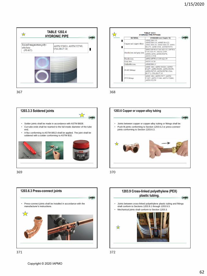
1/15/2020
62
TABLE 1202.4
HYDRONIC PIPE
1203.3.3 Soldered joints
• Solder joints shall be made in accordance with ASTM B828.
• Cut tube ends shall be reamed to the full inside diameter of the tube
end.
• A flux conforming to ASTM B813 shall be applied. The joint shall be
soldered with a solder conforming to ASTM B32.
1203.6 Copper or copper-alloy tubing
• Joints between copper or copper-alloy tubing or fittings shall be:
• Push-fit joints conforming to Section 1203.6.2 or press-connect
joints conforming to Section 1203.6.3.
1203.6.3 Press-connect joints
• Press-connect joints shall be installed in accordance with the
manufacturer’s instructions.
1203.9 Cross-linked polyethylene (PEX)
plastic tubing.
• Joints between cross-linked polyethylene plastic tubing and fittings
shall conform to Sections 1203.9.1 through 1203.9.3.
• Mechanical joints shall conform to Section 1203.3.
367 368
369 370
371 372
Copyright © 2020 IAPMO

1/15/2020
63
1203.9.3 Push-fit joints
• Push-fit joints that create a seal on the outside diameter of the
tubing shall not be used with tubing that has an ethylene vinyl
alcohol copolymer (EVOH) oxygen barrier layer.
1203.14 Raised temperature polyethylene (PE-RT)
plastic tubing.
• Joints between raised temperature polyethylene
tubing and fittings shall conform to Sections
1203.14.1 through 1203.14.3.
• Mechanical joints shall conform to Section 1203.3.
1203.14.3 Push-fit joints
• Push-fit joints that create a seal on the outside diameter of the
tubing shall not be used with tubing that has an ethylene vinyl
alcohol copolymer (EVOH) oxygen barrier layer.
TESTS
• 1208.1 General
• Exception:
For PEX piping systems, testing with
compressed gas shall be an alternative to
hydrostatic testing where compressed air or
other gas pressure testing is specifically
authorized by all of the manufacturers’
instructions for the PEX pipe and fitting
products installed at the time the system is being
tested, and compressed air or other gas testing is
not otherwise prohibited by applicable codes, laws
or regulations outside of this code.
1209.3 Embedded joints
• Joints of pipe or tubing that are embedded in a portion of the
building, such as concrete or plaster, shall be in accordance with the
requirements of Sections 1209.3.1 through 1209.3.5.
Fitting used to make a
tight bend
1209.3.5 Cross-linked polyethylene (PEX) joints
• PEX tubing shall be installed in continuous lengths or shall be joined
by hydronic fittings listed in Table 1202.5.
373 374
375 376
377 378
Copyright © 2020 IAPMO

1/15/2020
64
1209.5 Thermal barrier required
• Radiant floor heating systems shall be provided with a thermal
barrier in accordance with Sections 1209.5.1 and 1209.5.2.
• Insulation R-values for slab-on-grade and suspended floor
installation shall be in accordance with the International Energy
Conservation Code
CHAPTER 13 IMC
FUEL OIL PIPING
AND STORAGE
1303.1.1 Joints between different piping materials
• Joints between different piping materials shall be made with
approved adapter fittings.
• Joints between different metallic piping materials shall be made with
approved dielectric fittings or copper-alloy converter fittings
CHAPTER 14
SOLAR THERMAL
SYSTEMS
379 380
381 382
383 384
Copyright © 2020 IAPMO

1/15/2020
65
GENERAL
SECTION 14011401.1 Scope
• This chapter shall govern the design, construction, installation,
alteration and repair of solar thermal systems, equipment and
appliances intended to utilize solar energy for space heating or
cooling, domestic hot water heating, swimming pool heating or
process heating
1401.4 Solar thermal equipment and appliances
• Solar thermal equipment and appliances shall conform to the
requirements of this chapter and ICC 900/SRCC 300.
• Solar thermal systems shall be listed and labeled in accordance with
ICC 900/SRCC 300 and shall be installed in accordance with the
manufacturer’s instructions and ICC 900/SRCC 300.
1401.4.1 Collectors and panels
• Solar thermal collectors and panels shall be listed and labeled in
accordance with ICC 901/SRCC 100.
DESIGN AND
INSTALLATION
SECTION 1402
1402.1 General
• The design and installation of solar thermal systems shall comply
with Sections 1402.1 through 1402.8.
• Solar thermal systems shall be listed and labeled in accordance with
ICC 900/SRCC 300 and shall be installed in accordance with the
manufacturer’s instructions and ICC 900/SRCC 300.
385 386
387 388
389 390
Copyright © 2020 IAPMO

1/15/2020
66
1402.2 Access
• Access shall be provided to solar
thermal equipment for maintenance.
• Solar thermal systems and
appurtenances shall not obstruct or
interfere with the operation of any
doors, windows or other building
components requiring operation or
access.
1402.2 Access
• Roof-mounted solar thermal equipment shall not obstruct or interfere with the operation of roof-mounted equipment, appliances, chimneys, roof hatches, smoke vents, skylights and other roof penetrations and openings.
1402.3 Pressure and temperature
• Solar thermal system components containing pressurized fluids
shall be protected against pressures and temperatures exceeding
design limitations with pressure and temperature relief valves or
pressure relief valves.
1402.3 Pressure and temperature
• System
components shall
have a working
pressure rating of
not less than the
setting of the
pressure relief
device.
1402.3.1 Relief device
• Each section of the
system in which
excessive pressures are
capable of developing
shall have a relief device
located so that a section
cannot be valved off or
otherwise isolated from a
relief device.
Shut off
valves
1402.3.1 Relief device
• Relief valves shall comply with the requirements of Section 1006.6.
• For indirect solar systems, pressure relief valves in solar loops shall
also comply with ICC 900/ SRCC 300.
391 392
393 394
395 396
Copyright © 2020 IAPMO
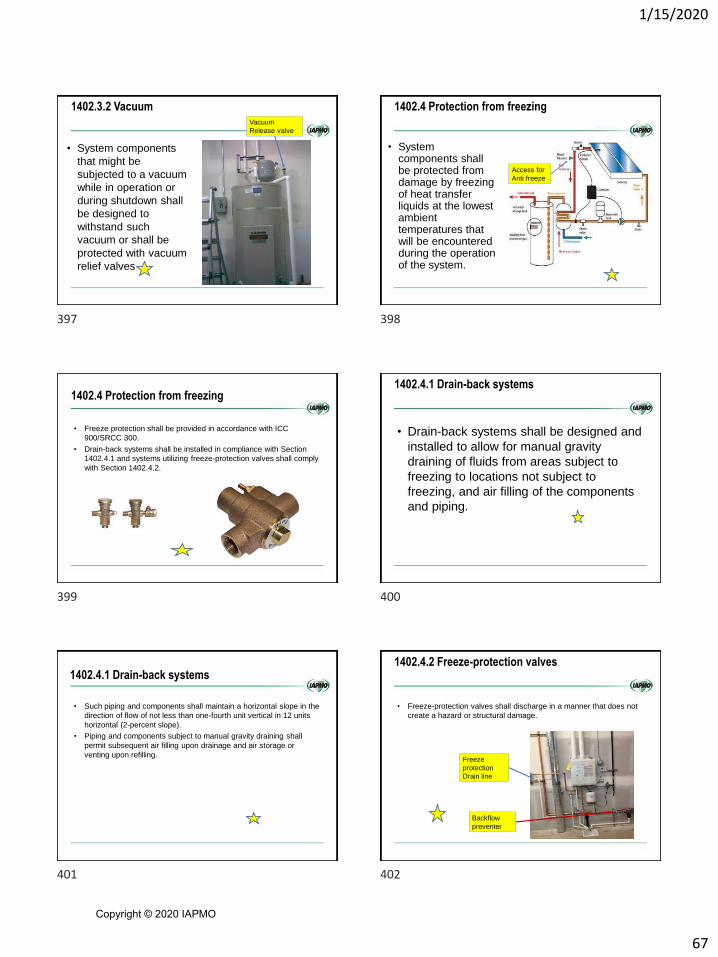
1/15/2020
67
1402.3.2 Vacuum
• System components
that might be
subjected to a vacuum
while in operation or
during shutdown shall
be designed to
withstand such
vacuum or shall be
protected with vacuum
relief valves
Vacuum
Release valve
1402.4 Protection from freezing
• System components shall be protected from damage by freezing of heat transfer liquids at the lowest ambient temperatures that will be encountered during the operation of the system.
Access for
Anti freeze
1402.4 Protection from freezing
• Freeze protection shall be provided in accordance with ICC
900/SRCC 300.
• Drain-back systems shall be installed in compliance with Section
1402.4.1 and systems utilizing freeze-protection valves shall comply
with Section 1402.4.2.
1402.4.1 Drain-back systems
• Drain-back systems shall be designed and
installed to allow for manual gravity
draining of fluids from areas subject to
freezing to locations not subject to
freezing, and air filling of the components
and piping.
1402.4.1 Drain-back systems
• Such piping and components shall maintain a horizontal slope in the
direction of flow of not less than one-fourth unit vertical in 12 units
horizontal (2-percent slope).
• Piping and components subject to manual gravity draining shall
permit subsequent air filling upon drainage and air storage or
venting upon refilling.
1402.4.2 Freeze-protection valves
• Freeze-protection valves shall discharge in a manner that does not
create a hazard or structural damage.
Freeze
protection
Drain line
Backflow
preventer
397 398
399 400
401 402
Copyright © 2020 IAPMO

1/15/2020
68
1402.5 Protection of potable water
• Where a solar thermal system heats potable water to supply a
potable hot water distribution or any other type of heating system,
the solar thermal system shall be in accordance with Sections
1402.5.1 through 1402.5.3 as applicable.
1402.5.1 Indirect systems
• Water supplies of any type shall not be connected to the solar
heating loop of an indirect solar thermal hot water heating system.
Solar Heating
loop
1402.5.1 Indirect systems
• This requirement shall not prohibit the presence of inlets or outlets
on the solar heating loop for the purposes of servicing the fluid in the
solar heating loop.
Antifreeze
fill
1402.5.2 Direct systems for potable water
distribution systems
• Where a solar thermal system directly heats potable water for a
potable water distribution system, the pipe, fittings, valves and other
components that are in contact with the potable water in the system
shall comply with the requirements of the International Plumbing
Code
1402.5.3 Direct systems for other than potable water
distribution systems
• Where a solar thermal system directly heats water for a system
other than a potable water distribution system, a potable water
supply connected to such system shall be protected against
backflow in accordance with the International Plumbing Code.
1402.6 Protection of equipment
• Solar thermal equipment exposed to vehicular traffic shall be
installed not less than 6 feet above the finished floor.
403 404
405 406
407 408
Copyright © 2020 IAPMO
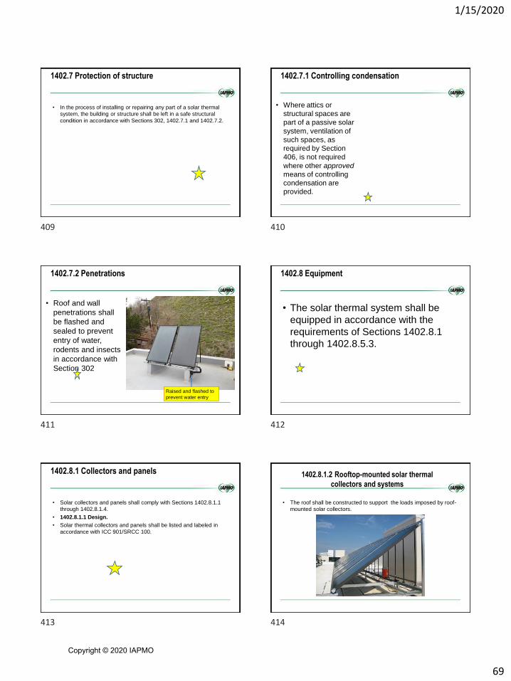
1/15/2020
69
1402.7 Protection of structure
• In the process of installing or repairing any part of a solar thermal
system, the building or structure shall be left in a safe structural
condition in accordance with Sections 302, 1402.7.1 and 1402.7.2.
1402.7.1 Controlling condensation
• Where attics or
structural spaces are
part of a passive solar
system, ventilation of
such spaces, as
required by Section
406, is not required
where other approved
means of controlling
condensation are
provided.
1402.7.2 Penetrations
• Roof and wall
penetrations shall
be flashed and
sealed to prevent
entry of water,
rodents and insects
in accordance with
Section 302
Raised and flashed to
prevent water entry
1402.8 Equipment
• The solar thermal system shall be
equipped in accordance with the
requirements of Sections 1402.8.1
through 1402.8.5.3.
1402.8.1 Collectors and panels
• Solar collectors and panels shall comply with Sections 1402.8.1.1
through 1402.8.1.4.
• 1402.8.1.1 Design.
• Solar thermal collectors and panels shall be listed and labeled in
accordance with ICC 901/SRCC 100.
1402.8.1.2 Rooftop-mounted solar thermal
collectors and systems
• The roof shall be constructed to support the loads imposed by roof-
mounted solar collectors.
409 410
411 412
413 414
Copyright © 2020 IAPMO

1/15/2020
70
1402.8.1.2 Rooftop-mounted solar thermal
collectors and systems
• Where mounted on or above the roof covering, the collector array
and supporting construction shall be constructed of noncombustible
materials or fire-retardant-treated wood conforming to the
International Building Code to the extent required for the type of roof
construction
1402.8.1.3 Collectors as roof covering
• Roof-mounted solar collectors that also serve as a roof covering
shall conform to the requirements for roof coverings in accordance
with the International Building Code.
• Exception:
The use of plastic solar collector covers shall be
limited to those approved light-transmitting
plastics meeting the requirements for plastic
roof panels in Section 2609 of the International
Building Code.
1402.8.1.4 Collector sensors
• Collector sensor installation, sensor location and the protection of
exposed sensor wires from degradation shall be in accordance with
ICC 900/SRCC 300, NFPA 70 and the collector manufacturer’s
instructions.
1402.8.2 Ducts
• Ducts utilized in solar heating and cooling systems shall be
constructed and installed in accordance with Chapter 6.
1402.8.2.1 Filtering
• Air transported to
occupied spaces
through dust-
producing materials by
means other than
natural convection
shall be filtered before
entering the occupied
space in accordance
with Section 605.
1402.8.3 Piping
• Potable piping shall be installed in accordance with the
International Plumbing Code.
• Hydronic piping shall be installed in accordance with Chapter 10
of this code.
• Mechanical system piping shall be supported in accordance with
Section 305
415 416
417 418
419 420
Copyright © 2020 IAPMO
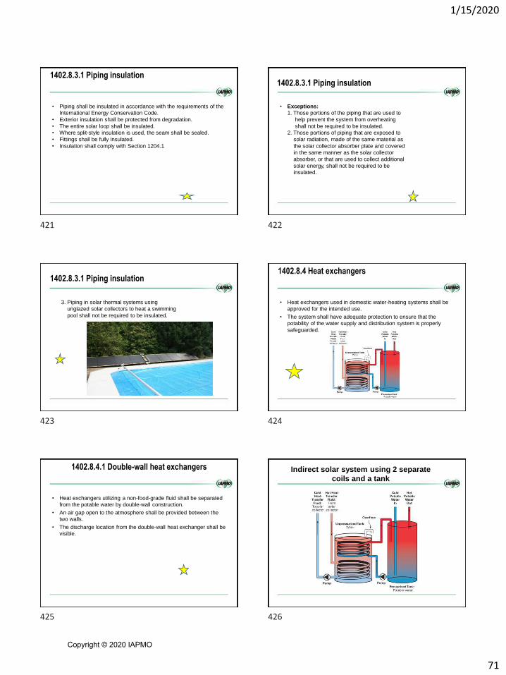
1/15/2020
71
1402.8.3.1 Piping insulation
• Piping shall be insulated in accordance with the requirements of the
International Energy Conservation Code.
• Exterior insulation shall be protected from degradation.
• The entire solar loop shall be insulated.
• Where split-style insulation is used, the seam shall be sealed.
• Fittings shall be fully insulated.
• Insulation shall comply with Section 1204.1
1402.8.3.1 Piping insulation
• Exceptions:
1. Those portions of the piping that are used to
help prevent the system from overheating
shall not be required to be insulated.
2. Those portions of piping that are exposed to
solar radiation, made of the same material as
the solar collector absorber plate and covered
in the same manner as the solar collector
absorber, or that are used to collect additional
solar energy, shall not be required to be
insulated.
1402.8.3.1 Piping insulation
3. Piping in solar thermal systems using
unglazed solar collectors to heat a swimming
pool shall not be required to be insulated.
1402.8.4 Heat exchangers
• Heat exchangers used in domestic water-heating systems shall be
approved for the intended use.
• The system shall have adequate protection to ensure that the
potability of the water supply and distribution system is properly
safeguarded.
1402.8.4.1 Double-wall heat exchangers
• Heat exchangers utilizing a non-food-grade fluid shall be separated
from the potable water by double-wall construction.
• An air gap open to the atmosphere shall be provided between the
two walls.
• The discharge location from the double-wall heat exchanger shall be
visible.
Indirect solar system using 2 separate
coils and a tank
421 422
423 424
425 426
Copyright © 2020 IAPMO
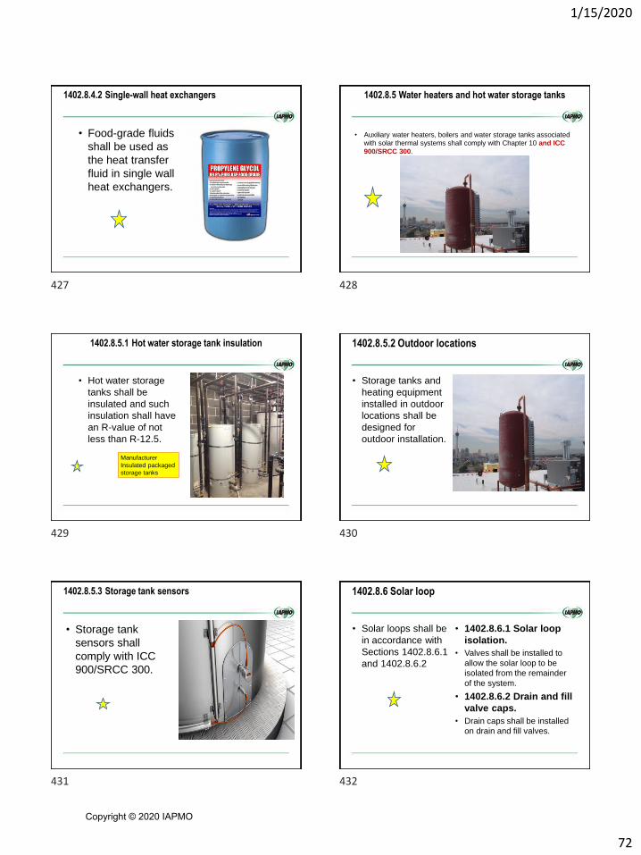
1/15/2020
72
1402.8.4.2 Single-wall heat exchangers
• Food-grade fluids
shall be used as
the heat transfer
fluid in single wall
heat exchangers.
1402.8.5 Water heaters and hot water storage tanks
• Auxiliary water heaters, boilers and water storage tanks associated
with solar thermal systems shall comply with Chapter 10 and ICC
900/SRCC 300.
1402.8.5.1 Hot water storage tank insulation
• Hot water storage
tanks shall be
insulated and such
insulation shall have
an R-value of not
less than R-12.5.
Manufacturer
Insulated packaged
storage tanks
1402.8.5.2 Outdoor locations
• Storage tanks and
heating equipment
installed in outdoor
locations shall be
designed for
outdoor installation.
1402.8.5.3 Storage tank sensors
• Storage tank
sensors shall
comply with ICC
900/SRCC 300.
1402.8.6 Solar loop
• Solar loops shall be
in accordance with
Sections 1402.8.6.1
and 1402.8.6.2
• 1402.8.6.1 Solar loop
isolation.
• Valves shall be installed to
allow the solar loop to be
isolated from the remainder
of the system.
• 1402.8.6.2 Drain and fill
valve caps.
• Drain caps shall be installed
on drain and fill valves.
427 428
429 430
431 432
Copyright © 2020 IAPMO

1/15/2020
73
1402.8.7 Expansion tanks
• Liquid single-phase solar energy systems shall be equipped with
expansion tanks sized in accordance with Section 1009, except that
additional expansion tank acceptance volume equal to the total
volume of liquid contained in the installed solar collectors and piping
above the collectors shall be included.
HEAT TRANSFER
FLUIDS
SECTION 1403
1403.2 Heat transfer fluids
• Heat transfer gases and liquids shall be rated to withstand the
system’s maximum design temperature under operating conditions
without degradation.
• Heat transfer fluids shall be in accordance with ICC 900/SRCC 300.
1403.3 Food-grade additives
• Any food-grade fluid used as a heat transfer fluid containing
additives shall be third-party listed by an approved agency to the
appropriate section of the Code of Federal Regulations, Title 21,
Food and Drugs, Chapter 1, Food and Drug Administration, Parts
174–186.
1403.4 Toxicity
• The use of toxic fluids shall comply with Title 15 of the Federal
Hazardous Substances Act and Chapter 60 of the International Fire
Code.
1403.5 Flammable gases and liquids
• A flammable liquid or gas shall not be utilized as a heat transfer
fluid.
• The flash point of liquids used in occupancies classified in Group H
or F shall not be lower unless approved.
433 434
435 436
437 438
Copyright © 2020 IAPMO

1/15/2020
74
LABELING
SECTION 14041404.1 Collectors
• Factory-built collectors shall bear a label showing the
manufacturer’s name and address, model number and serial
number.
1404.2 Water storage tanks
• Pressurized water storage tank shall bear a label showing the
manufacturer’s name and address, model number, serial number,
storage unit maximum and minimum allowable operating
temperatures, and storage unit maximum and minimum allowable
operating pressures.
• The label shall clarify that these specifications apply only to the
water storage tanks.
Manufacturer’s name and Other required information
1404.3 Fluid safety labeling
• Drain and fill valves shall be labeled with a description and warning
that identifies the fluid in that loop as “Potable Water,” “Food-
Grade Fluid,”
• “Non-Food-Grade Fluid” or “Toxic.”
• Labeling shall also be provided that reads as follows: “Fluid could
be discharged at high temperature or pressure or both.
• Unauthorized alterations to this system could result in a health
hazard or a hazardous condition.”
1404.4 Heat exchangers
• Heat exchangers shall be labeled to indicate the heat exchanger
type with one of the following:
1. “Single-wall without leak protection.”
2. “Double-wall without leak protection.”
3. “Double-wall with leak protection.”
439 440
441 442
443 444
Copyright © 2020 IAPMO

NOTES _____________________________________________________________________________________
_____________________________________________________________________________________
_____________________________________________________________________________________
_____________________________________________________________________________________
_____________________________________________________________________________________
_____________________________________________________________________________________
_____________________________________________________________________________________
_____________________________________________________________________________________
_____________________________________________________________________________________
_____________________________________________________________________________________
_____________________________________________________________________________________
_____________________________________________________________________________________
_____________________________________________________________________________________
_____________________________________________________________________________________
_____________________________________________________________________________________
_____________________________________________________________________________________
_____________________________________________________________________________________
_____________________________________________________________________________________
_____________________________________________________________________________________
_____________________________________________________________________________________
_____________________________________________________________________________________
_____________________________________________________________________________________
_____________________________________________________________________________________
_____________________________________________________________________________________