2017 operator’s manual - tycrop manufacturing...
TRANSCRIPT

MOVING FLOOR TRAILER
2017 OPERATOR’S MANUAL
SMOOTHFLOW

Manual Information
Manual ID 1100-3509
Revision 00 | First printing - January 2017
Copyright © 2017 TYCROP Transport Solutions
Operator’s Manual | Moving Floor Trailer 1
Contents
Contents3 Introduction
4 Trailer Identification
5 One Year Warranty
7 Safety
9 Truck and Trailer Connection9 Truck and Trailer Connection
10 Truck and Trailer Disconnection
13 Loading and Unloading Operation13 Loading Operation
13 Unloading Operation
15 Ladder and Platform 15 Interior Ladder
15 Front Ladder and Platform
16 Rear Step Ladder
17 Option: Manual Roll Tarp17 Opening Tarp
18 Closing Tarp
21 Option: Flip-Top Tarp21 Controls
21 Opening tarp
22 Closing tarp
25 Option: Automatic Lift Axle25 Switch and Connection
25 Position Indicator Light
25 Operation switch
27 Option: Moving Floor by Keith®
27 Floor Operation Decals
28 Operation
31 Option: Barn Doors31 Opening Barn Doors
31 Closing Barn Doors
33 Option: Top Hinge Door33 Opening Top Hinge Door
33 Closing Top Hinge Door
35 Option: Combo Door35 Opening Barn Doors
35 Closing Barn Doors
35 Opening Top Hinge Door
35 Closing Top Hinge Door
37 Option: Clean Out Wall
39 Maintenance39 General Maintenance
39 Air Tanks
39 Brake Chambers
39 Electrical
39 Glad Hands
40 Drum Brakes
40 Drum Brake Stroke Inspections
40 Hub Oil
40 Moving Floor: Keith®
41 Ride Height Adjustment
41 Trailer Frame and Body
41 Wheels
41 Lubrication
41 Other Manufacturers
42 Wet Kit Information42 Wet Kit: Keith®
44 Schematics
50 Parts Overview

2

Operator’s Manual | Moving Floor Trailer 3
IntroductionAbout this ManualThis operator’s manual is intended to provide basic operational instructions, safety precautions, and maintenance information. Read this manual and fully understand all safety hazards around the trailer prior to operation. It is recommended that a copy of this manual be kept with the equipment at all times. The most recent manual revisions will be posted on the TYCROP Transport Solutions website.
For detailed information on the operation and maintenance of components made by other manufacturers, see the corresponding manufacturer’s maintenance schedule and/or operator’s manual on the TYCROP Transport Solutions website.
ContactTYCROP Transport Solutions provides part sales, warranty, and product support worldwide. Please have your VIN number ready when calling for support.
Customer CarePhone: 1.877.892.7676Fax: 1.604.794.3446Email: [email protected]: www.tycrop.ca
Hours: 8:30 am - 4:30 pm (PST) Monday - Friday
Parts Support Warranty
Introduction

4
Trailer IdentificationFill in your trailer VIN below for your record.
VIN
Trailer Identification

Operator’s Manual | Moving Floor Trailer 5
One Year WarrantyManufacturer’s ResponsibilityTYCROP Manufacturing Ltd. (On behalf of TYCROP Transport Solutions) warrants each item of its own manufacture to be free from defects in material or workmanship. Should any part be found under normal use and service to be defective, the Manufacturer will repair or replace said parts, F.O.B. Factory. This is provided said parts are returned to the Manufacturer’s plant (freight pre-paid) and that such parts are judged by the Manufacturer to be defective.
Warranty Start DateThe starting date shall be determined as that date shown on the Invoice or Bill of Sale entered into at time of sale to the owner.
Labour ConsiderationIf TYCROP Manufacturing Ltd., in its sole discretion, determined that a repair facility other than the factory shall perform the warranty work, TYCROP will pay a specified labour amount for repair or replacement as determined and approved by TYCROP, before any such work has started.
Components by Other ManufacturersTYCROP Manufacturing Ltd. does not warranty items, parts or machinery furnished by it but not of its own manufacture, except for any warranties extended by the manufacturer of such parts or machinery.
Product Owner ResponsibilitiesOwner is solely responsible for pre-operation inspection, daily inspections, periodic inspections, maintenance and use of the product in accordance with government requirements and manufacturer’s specifications as established at the time of manufacture.
Owner is responsible for communication expenses, meals, lodging and incidental costs incurred by owner or employees of the owner as a result of warrantable failure.
Owner is responsible for “down time” expenses, cargo damage, and all business costs and losses resulting from a warrantable failure.
Owner is responsible to provide TYCROP Manufacturing Ltd. with accurate information, concerning the specification of a particular piece of equipment, and accurate details on the environment it will operate in. The owner is required to approve the final design of the piece of equipment, and its suitability for a particular application.
One Year Warranty
Special Order EquipmentOwner is responsible to provide TYCROP Manufacturing Ltd. with accurate information concerning accurate specification of a particular piece of equipment, and accurate details on the environment it will operate in. The owner is required to approve the final design of the piece of equipment, and its suitability for a particular application. A statement of vehicle or machine usage is included with this documentation.
Additional Warranty LimitationThe foregoing warranty does not apply to equipment that has been altered, changed, or repaired in any manner whatsoever.
The above mentioned warranty is void in all respects when in the manufacturer’s judgment the equipment has been subject to misuse, negligence, or accident, or used for an application other than outlined in the Statement of Machine Usage without prior approval of the manufacturer.
These warranties are the sole warranties of TYCROP Manufacturing Ltd. There are no other warranties expressed or implied.
Warranty Claim ProceduresClaims can be made by phoning TYCROP Transport Solutions at 1.877.892.7676.
For a claim to be considered, it must contain adequate documentation which states vehicle mileage, the starting date and the trailer or product serial number.
Note: Absolutely no claims will be considered unless the repair has been approved and a TYCROP claim number assigned before the repair is initiated.

6
Operator’s Manual | Moving Floor Trailer 7
Safety
SafetyGeneral SafetyRead this operator’s manual and fully understand all safety hazards around the trailer prior to operation.
• Always ensure that the surrounding area is clear of personnel and debris before connecting or disconnecting the truck and trailer or performing work on the truck and trailer.
• Tarping Platform maximum capacity is 350 lbs / 158 kg.
• Maximum one person on tarping platforms.
• Do not deploy platforms when pup trailer is disconnected. Fall hazard.
• Never go under the trailer during operation.
• Exercise caution when using the ladders and platform with which the trailer is equipped. There is an inherent risk of falling or personal injury when using the ladders or platforms, as with any situation where the operator is working at a height.
• Never shift the gears of the landing gear while under load.
• While using the landing gear, always lift or lower the trailer in low gear. Serious injury may occur from lifting or lowering while in high gear.
• Ensure that there are no power lines above or along side of the trailer before operating the flip-top tarp.
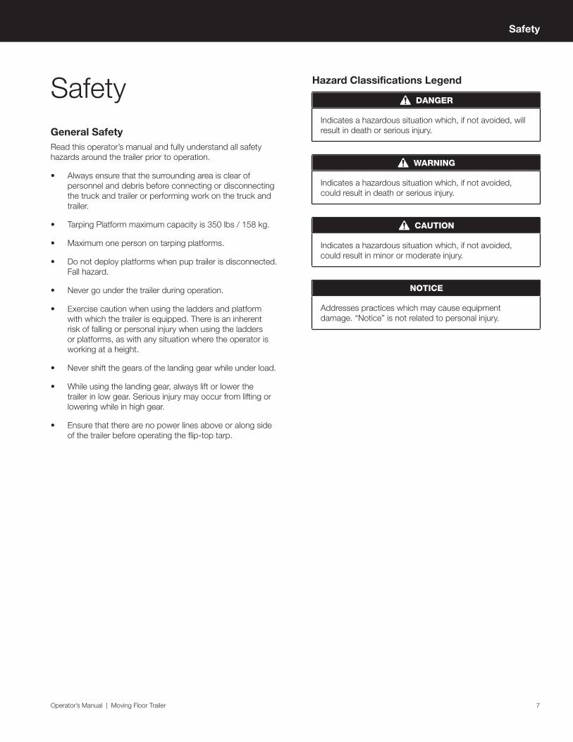
Hazard Classifications Legend
DANGER
Indicates a hazardous situation which, if not avoided, will result in death or serious injury.
WARNING
Indicates a hazardous situation which, if not avoided, could result in death or serious injury.
CAUTION
Indicates a hazardous situation which, if not avoided, could result in minor or moderate injury.
NOTICE
Addresses practices which may cause equipment damage. “Notice” is not related to personal injury.

8

Operator’s Manual | Moving Floor Trailer 9
Truck and Trailer Connection Operation - 1
Truck and Trailer ConnectionTruck and Trailer Connection
CAUTION
Ensure that the surrounding area is clear of personnel and debris before connecting truck and trailer.
1. Back the truck up to the trailer, centering the fifth wheel with the kingpin. Stop before contact is made with the trailer (Figure 01 - 1).
Figure 01 - 1
2. Check to see that the trailer clears the back of the truck. Adjust the trailer height using the landing gear as needed (Figure 02 - 1). The fifth wheel should make contact with the trailer approximately 15 cm or 6 inches behind the bracket pin (Figure 03 - 1). Now connect the trailer.
Figure 02 - 1
Figure 03 - 1
3. Perform a pull test and visually check that the fifth wheel jaws have fully locked around the kingpin (Figure 04 - 1).
Figure 04 - 1
4. Connect the air lines (Figure 05 - 1), electrical line (Figure 06 - 1) and hydraulic lines (Figure 07 - 1) from the truck to the connections on the front of the trailer.
Figure 05 - 1
Figure 06 - 1
10
Figure 07 - 1
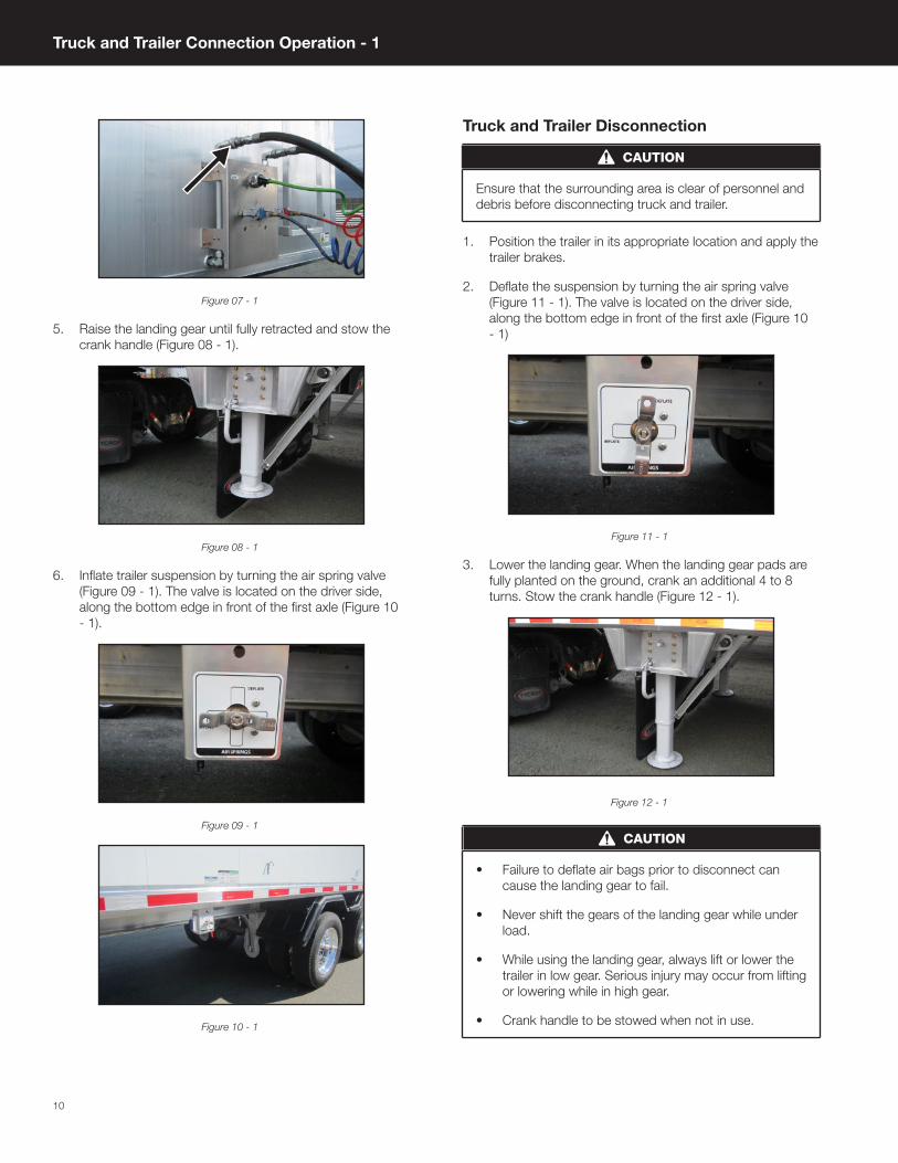
5. Raise the landing gear until fully retracted and stow the crank handle (Figure 08 - 1).
Figure 08 - 1
6. Inflate trailer suspension by turning the air spring valve (Figure 09 - 1). The valve is located on the driver side, along the bottom edge in front of the first axle (Figure 10 - 1).
Figure 09 - 1
Figure 10 - 1
Truck and Trailer Disconnection
CAUTION
Ensure that the surrounding area is clear of personnel and debris before disconnecting truck and trailer.
1. Position the trailer in its appropriate location and apply the trailer brakes.
2. Deflate the suspension by turning the air spring valve (Figure 11 - 1). The valve is located on the driver side, along the bottom edge in front of the first axle (Figure 10 - 1)
Figure 11 - 1
3. Lower the landing gear. When the landing gear pads are fully planted on the ground, crank an additional 4 to 8 turns. Stow the crank handle (Figure 12 - 1).
Figure 12 - 1
CAUTION
• Failure to deflate air bags prior to disconnect can cause the landing gear to fail.
• Never shift the gears of the landing gear while under load.
• While using the landing gear, always lift or lower the trailer in low gear. Serious injury may occur from lifting or lowering while in high gear.
• Crank handle to be stowed when not in use.
Truck and Trailer Connection Operation - 1

Operator’s Manual | Moving Floor Trailer 11
4. Disconnect the hydraulic lines (Figure 13 - 1), electrical line (Figure 14 - 1), and air lines (Figure 15 - 1) from the front of the trailer.
Figure 13 - 1
Figure 14 - 1
Figure 15 - 1
CAUTION
Air and hydraulic lines may be under pressure. Grip the lines firmly during disconnection
5. Disengage fifth wheel by pulling lever out (Figure 16 - 1). Now pull truck forward until it is clear of trailer.
Figure 16 - 1
Truck and Trailer Connection Operation - 1

12

Operator’s Manual | Moving Floor Trailer 13
Loading and Unloading OperationLoading Operation1. Ensure that the loading location is located on hard-
packed and level ground. Then position the trailer as desired and apply the brakes.
2. Close and secure the rear doors (Figure 01 - 2). (Refer to Option: Barn Doors on page 31), (Refer to Option: Top Hinge Door on page 33) Or (Refer to Option: Combo Door on page 35)
Figure 01 - 2
WARNING
Doors must be closed and secured prior to loading trailer from above.
3. Open the tarp (Figure 02 - 2). (Refer to Option: Manual Roll Tarp on page 17) Or (Refer to Option: Flip-Top Tarp on page 21)
Figure 02 - 2
4. Load the trailer.
CAUTION
Ensure the surrounding area is clear of personnel and obstructions prior to loading the trailer.
WARNING
Do not exceed the maximum allowable GVWR / PNBE KG and GAWR / PNBE KG as indicated on the VIN plate. The VIN plate is located on the front driver side corner of the trailer.
5. Close the tarp. (Refer to Option: Manual Roll Tarp on page 17) Or (Refer to Option: Flip-Top Tarp on page 21)
6. Perform a pre-trip inspection.
Unloading Operation1. Ensure that the unloading location is located on hard-
packed and level ground. Then position the trailer and apply the brakes.
2. Deflate the suspension by turning the air spring valve (Figure 03 - 2). The valve is located on the driver side, along the bottom edge in front of the first axle (Figure 04 - 2).
Figure 03 - 2
Figure 04 - 2
Loading and Unloading Operation - 2

14
3. Turn on PTO (power take off).
CAUTION
Ensure that the moving floor is set to neutral. The floor will start to move as soon as the power take off (PTO) is engaged.
4. Open the rear doors (Figure 05 - 2). (Refer to Option: Barn Doors on page 31), (Refer to Option: Top Hinge Door on page 33) Or (Refer to Option: Combo Door on page 35)
Figure 05 - 2
DANGER
Depending on the material being hauled, the load can potentially settle and put extreme pressure on the rear doors. Use caution, as the door may burst open when opening.
Unload payload using the supplied moving floor (Figure 06 - 2). (Refer to Option: Moving Floor by Keith® on page 27)
Figure 06 - 2
5. Close and secure the rear doors (Figure 07 - 2). (Refer to Option: Barn Doors on page 31), (Refer to Option: Top Hinge Door on page 33) Or (Refer to Option: Combo Door on page 35)
Figure 07 - 2
6. Close the tarp. (Refer to Option: Manual Roll Tarp on page 17) Or (Refer to Option: Flip-Top Tarp on page 21)
7. Inflate trailer suspension by turning the air spring valve (Figure 08 - 2). The valve is located on the driver side, along the bottom edge in front of the first axle (Figure 09 - 2).
Figure 08 - 2
Figure 09 - 2
8. Perform a pre-trip inspection.
Loading and Unloading Operation - 2

Operator’s Manual | Moving Floor Trailer 15
Ladder and Platform
WARNING
Risk of falling or personal injury. Use ladders and platform with care.
Interior LadderThe interior ladder is intended for use as an emergency exit only. This stationary ladder can be found inside, on the front wall (Figure 01 - 3).
Figure 01 - 3
Front Ladder and PlatformThe front ladder is for accessing the front platform (Figure 02 - 3) when opening and closing the tarp, if equipped.
Figure 02 - 3
1. Platform access hatch must be lowered (Figure 03 - 3) while personnel are on platform.
Figure 03 - 3
2. To secure the front platform hatch (Figure 03 - 3), lift the platform until the magnet (Figure 04 - 3) contacts the metal plate (Figure 05 - 3).
Figure 04 - 3
Figure 05 - 3
Ladder and Platform - 3

16
Rear Step Ladder
CAUTION
Only use grab handle when the passenger side door is secured open (Figure 06 - 3).
Figure 06 - 3
The rear step ladder is located on the rear passenger side corner above the light bar (Figure 07 - 3).
Figure 07 - 3
1. Pull the rear step ladder out until it is fully extended (Figure 08 - 3) and lower it (Figure 09 - 3).
Figure 08 - 3
Figure 09 - 3
2. When climbing the ladder, use the grab handle located on the passenger side rear door post (Figure 06 - 3).
3. To stow the ladder, lift the rear step ladder (Figure 10 - 3) and push it in until the clasp is fully engaged around the bar (Figure 11 - 3).
Figure 10 - 3
Figure 11 - 3
Ladder and Platform - 3

Operator’s Manual | Moving Floor Trailer 17
Option: Manual Roll TarpOpening Tarp1. Remove tarp securements, e.g. bungee cords (Figure 01
- 4), straps if equipped (Figure 02 - 4), and cinches and cables if equipped (Figure 03 - 4), along the driver side of the trailer. Cinches should be hung on nearby hooks to avoid damaging the trailer. (Figure 03 - 4).
Figure 01 - 4
Figure 02 - 4
Figure 03 - 4
CAUTION
The tarp securements are under tension.
2. Climb front ladder (Figure 04 - 4). (Refer to Front Ladder and Platform on page 15)
Figure 04 - 4
3. From the platform, roll the tarp up using the crank handle (Figure 05 - 4), which is located in the holder on the front wall beside the ladder. Insert the square end of the crank handle into tarp tube. (Figure 06 - 4). Once the tarp is rolled up against the tarp stops (Figure 07 - 4), stow the tarp crank handle in the holder.
Figure 05 - 4
Figure 06 - 4
Figure 07 - 4
Option: Manual Roll Tarp - 4

18
4. Lift platform hatch and secure it (Figure 08 - 4). The hatch is secure when the magnet makes contact with the metal plate on the hatch (Figure 09 - 4). Climb down from the platform using the ladder.
Figure 08 - 4
Figure 09 - 4
Closing TarpUsing Tarp Pull Rope (if equipped)
1. Toss the tarp pull rope (Figure 10 - 4) over the top to the opposite side of trailer. Pull the rope until the tarp is fully unrolled.
Figure 10 - 4
CAUTION
Ensure that the opposite side of the trailer is clear of personnel before tossing the tarp pull rope over.
2. Secure tarp with provided securements. (Refer to Tarp Hook and securements on page 19)
Using Tarp Crank Handle
1. Climb front ladder (Figure 11 - 4). (Refer to Front Ladder and Platform on page 15)
Figure 11 - 4
2. From the platform, unroll the tarp using the crank handle, which is located in the holder on the front wall beside the ladder (Figure 12 - 4). Insert the square end of the crank handle into the tarp tube (Figure 13 - 4). Unroll the tarp until it is fully unrolled (Figure 14 - 4). Stow crank handle in the holder (Figure 15 - 4).
Figure 12 - 4
Option: Manual Roll Tarp - 4

Operator’s Manual | Moving Floor Trailer 19
Figure 13 - 4
Figure 14 - 4
Figure 15 - 4
Tarp Hook and Securements
1. Use the tarp hook (Figure 16 - 4) to pull the tarp securements down from the top of the tarp. The tarp hook is located on the driver side of the front exterior ladder (Figure 17 - 4).
Figure 16 - 4
Figure 17 - 4
2. To stow the tarp hook, insert the hook end into the opening at the top of the ladder (Figure 18 - 4) and secure the handle end in the clevis at the bottom of the ladder with the linch pin (Figure 19 - 4).
Figure 18 - 4
Figure 19 - 4
3. Re-attach tarp securements (See below).
Bungee Cords
Secure the bungee cords to the supplied hooks along the driver side. If equipped with rear tarp flaps, secure the bungee cords along the rear door (Figure 20 - 4).
Figure 20 - 4
Option: Manual Roll Tarp - 4

20
Cinches and Cables (if equipped)
Raise cinch handle and connect cinch hook to chain. Pull handle down to lock cinch. Do not over-tighten cinches. Do not use load bar. The free end of the chain may be hung on cinch hook to avoid excessive swinging (Figure 21 - 4).
Figure 21 - 4
NOTICE
Over-tightening tarp cinches may lead to premature tarp wear.
Straps (if equipped)
Take the loose end of the strap with the hook and connect to the tarp cable. Tighten it (Figure 22 - 4).
Figure 22 - 4
Tarp Pull Rope (if equipped)
Wrap the rope around the provided hooks and secure with the bungee cord (Figure 23 - 4).
Figure 23 - 4
Option: Manual Roll Tarp - 4

Operator’s Manual | Moving Floor Trailer 21
Option: Flip-Top Tarp
WARNING
Ensure that there are no power lines above or alongside the trailer before operating the flip-top tarp.
CAUTION
Always transport the trailer with the tarp in the closed position.
When trailer is not in use, store the tarp in the open position.
Only use tarps that are supplied with the flip-top tarp system. Other tarps may cause system failure and voiding of the warranty.
ControlsSelector Valve
The selector valve (Figure 01 - 5) is located on the driver side front corner of the front wall (Figure 02 - 5).
Figure 01 - 5
Figure 02 - 5
Control Valve
The control valve (Figure 03 - 5) is located on the driver side front corner of the front wall (Figure 04 - 5).
Figure 03 - 5
Figure 04 - 5
Opening tarp
NOTICE
Always open driver side flip-top first.
1. Pull out the selector valve (Figure 05 - 5) for flip-top operation.
Figure 05 - 5
Option: Flip-Top Tarp - 5

22
2. Open the driver side tarp by pushing the control valve down (Figure 06 - 5) until fully open (Figure 07 - 5).
Figure 06 - 5
Figure 07 - 5
CAUTION
Beware of falling debris while opening tarp.
Ensure area is clear of obstructions prior to opening tarp.
3. Open the passenger side tarp by pushing the control valve down (Figure 08 - 5) until fully open (Figure 09 - 5).
Figure 08 - 5
Figure 09 - 5
CAUTION
Beware of falling debris while opening tarp.
Ensure area is clear of obstructions prior to opening tarp.
Closing tarp
NOTICE
Always close passenger side tarp first.
1. Close the passenger side tarp by pushing the control valve up (Figure 10 - 5) until fully closed (Figure 11 - 5).
Figure 10 - 5
Figure 11 - 5
Option: Flip-Top Tarp - 5
Operator’s Manual | Moving Floor Trailer 23
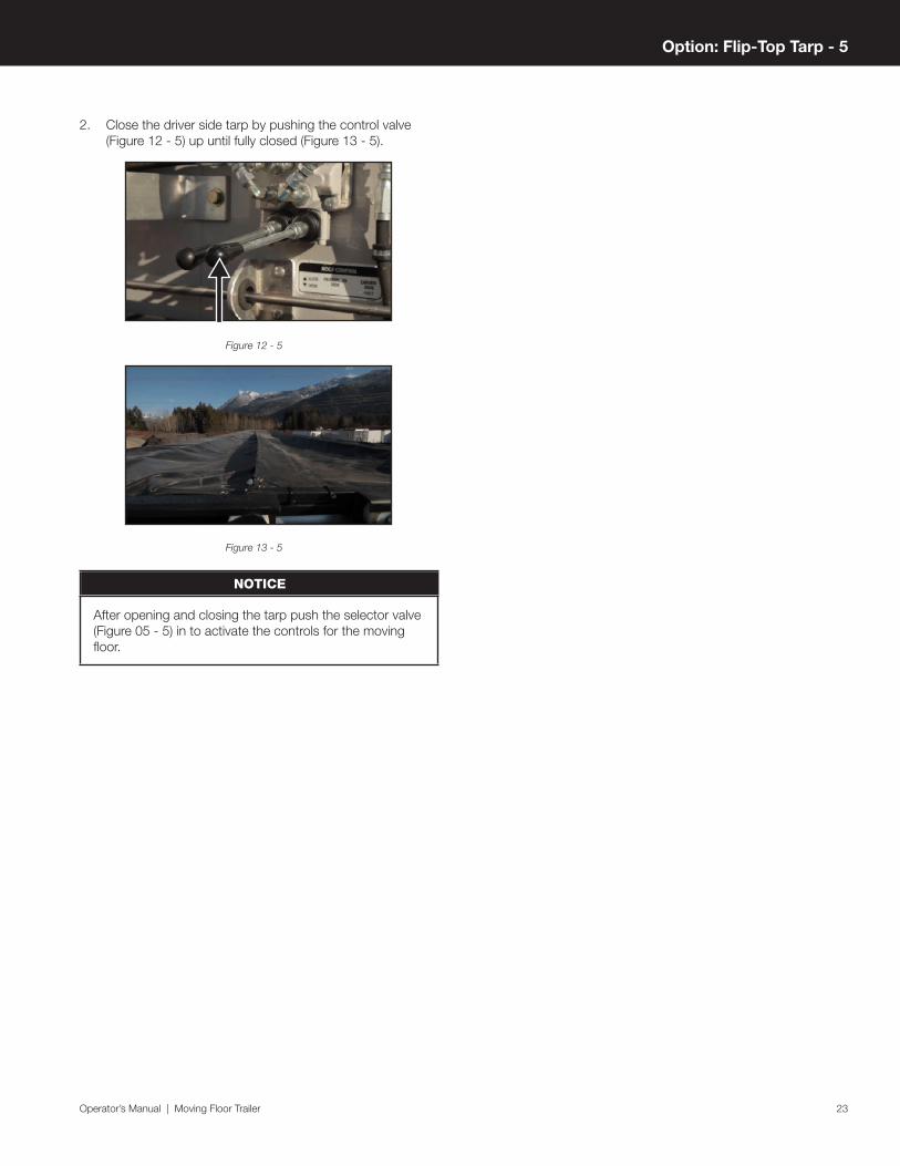
2. Close the driver side tarp by pushing the control valve (Figure 12 - 5) up until fully closed (Figure 13 - 5).
Figure 12 - 5
Figure 13 - 5
NOTICE
After opening and closing the tarp push the selector valve (Figure 05 - 5) in to activate the controls for the moving floor.
Option: Flip-Top Tarp - 5

24

Operator’s Manual | Moving Floor Trailer 25
Option: Automatic Lift AxleSwitch and ConnectionThe operation switch for the lift axle (Figure 01 - 6) is located in front of the first axle. The electrical wire (7 pin) and glad hands (blue and red) must be connected from the truck to the trailer (Figure 02 - 6), in order for the lift axle to function.
Figure 01 - 6
Figure 02 - 6
Position Indicator LightWhen the lift axle is in the raised position, the blue indicator light will be illuminated (Figure 03 - 6). The blue indicator light is located on the driver side in front of the first axle.
Figure 03 - 6
Operation switchAutomatic
When the switch is toggled to “automatic”, the axle will automatically raise and lower, depending on the weight of the load in the trailer (Figure 04 - 6).
TYCROP MFG. LTD.
1100
-443
6
AUTO
DOWN
LIFT AXLES
Figure 04 - 6
Down
When the switch is toggled to “down”, the axle will lower and stay lowered (Figure 05 - 6).
TYCROP MFG. LTD.
1100
-443
6
AUTO
DOWN
LIFT AXLES
Figure 05 - 6
Option: Automatic Lift Axle - 6

26

Operator’s Manual | Moving Floor Trailer 27
Option: Moving Floor by Keith®
General Safety
CAUTION
Read the Keith® moving floor Operator’s Manual and fully understand all safety hazards around the floor prior to operation.
The Keith® moving floor Operator’s Manual can be found on the TYCROP Transport Solutions website.
• The floor will start to move when the drive system is switched on.
• Check that the PTO on the truck is compatible with your moving floor. (Refer to Keith® wet kit diagram on page 27)
• Never operate floor with doors closed.
• Never stand where the load discharges.
• Never adjust the unloading mechanism with the floor operating.
• Never go under the trailer during operations.
• Never leave trailer unattended while in operation.
• Never operate the moving floor when safety covers are removed.
• Never operate the moving floor while personnel are inside the trailer.
• Always keep hands, body parts and loose clothing away from drive unit during operation.
• Always disconnect the power take off (PTO) before commencing any maintenance procedure.
• Always disconnect power supply before going under the trailer.
• Always keep clear of any oil leaks when the hydraulic pressure is high.
• Always disconnect the power take off (PTO) before moving trailer.
Floor Operation Decals
Option: Moving Floor by Keith® - 7

28
OperationTo unload and load the trailer using the moving floor, use the control levers (Figure 01 - 7) located on the driver side, along the bottom edge in front of the first axle (Figure 02 - 7).
Figure 01 - 7
Figure 02 - 7
Stopping
Push the handle IN on the left to stop the floor at any time during the loading and unloading process (Figure 03 - 7).
View from side of trailer
View from under trailer
Figure 03 - 7
Unloading
Pull the handle on the right OUT. Now pull the handle on the left OUT (Figure 04 - 7) to start the unloading process.
NOTICE
As the trailer unloads, you will need to move the trailer forward when the load reaches the top of the trailer deck.
View from side of trailer
View from under trailer
Figure 04 - 7
Option: Moving Floor by Keith® - 7

Operator’s Manual | Moving Floor Trailer 29
Loading
Push the handle on the right OUT. Now push the handle on the left IN (Figure 05 - 7) to start the unloading process.
View from side of trailer
View from under trailer
Figure 05 - 7
NOTICE
Return the floor slats to the forward position when the moving floor is not in use (Figure 06 - 7).
Figure 06 - 7
Option: Moving Floor by Keith® - 7

30

Operator’s Manual | Moving Floor Trailer 31
Option: Barn Doors
DANGER
Depending on the material being hauled, the load can potentially settle and put extreme pressure on the rear doors. Use caution - the door may burst open when opening.
Opening Barn Doors1. Release the latch (Figure 01 - 8) on the passenger side
barn door and open the door. Secure the door open using the spring latch (Figure 02 - 8) on the rear side corner of the trailer.
Figure 01 - 8
Figure 02 - 8
2. Release the latch (Figure 03 - 8) on the driver side barn door and open the door. Secure the door open using the spring latch (Figure 04 - 8) on the rear corner of the trailer.
Figure 03 - 8
Figure 04 - 8
Closing Barn Doors1. Remove the spring latch which is holding the driver side
barn door open and stow it (Figure 05 - 8). Close and secure the door using the handle (Figure 06 - 8).
Figure 05 - 8
Figure 06 - 8
Option: Barn Doors - 8

32
2. Remove the spring latch which is holding the passenger side barn door open and stow it (Figure 07 - 8). Close and secure the door using the handle (Figure 08 - 8).
Figure 07 - 8
Figure 08 - 8
Option: Barn Doors - 8

Operator’s Manual | Moving Floor Trailer 33
Option: Top Hinge Door
DANGER
Depending on the material being hauled, the load can potentially settle and put extreme pressure on the rear doors. Use caution - the door may burst open when opening.
Opening Top Hinge DoorRelease the lever (Figure 01 - 9) on the driver side rear corner of the trailer. Rotate the lever up 90 degrees until the hook end is clear from the pin (Figure 02 - 9) and secure with the provided chain and hook (Figure 03 - 9).
Figure 01 - 9
Figure 02 - 9
Figure 03 - 9
Closing Top Hinge DoorRelease the lever (Figure 04 - 9) on the driver’s side rear corner of the trailer. Rotate the lever down 90 degrees until the hook end is hooked around the pin (Figure 05 - 9) and secure with the provided chain and hook (Figure 06 - 9).
Figure 04 - 9
Figure 05 - 9
Figure 06 - 9
Option: Top Hinge Doors - 9

34

Operator’s Manual | Moving Floor Trailer 35
Option: Combo Door
DANGER
Depending on the material being hauled, the load can potentially settle and put extreme pressure on the rear doors. Use caution - the door may burst open when opening.
CAUTION
Ensure that the top hinge door is closed and secure before unlatching and opening barn doors.
Opening Barn Doors(Refer to Opening Barn Doors on page 35)
Closing Barn Doors(Refer to Closing Barn Doors on page 35)
Opening Top Hinge Door(Refer to Opening Top Hinge Door on page 35)
Closing Top Hinge Door(Refer to Closing Top Hinge Door on page 35)
Option: Top Hinge Doors - 10

36

Operator’s Manual | Moving Floor Trailer 37
Option: Clean Out Wall - 11
Option: Clean Out WallThe following information will help ensure that your Cleanout Wall operates as effectively as possible. Below are the set-up and operational instructions for drivers using the Cleanout Wall, as well as some information about different kinds of products and how their properties will affect the wall’s performance.
Cleanout Wall Set-Up and UsePrior to Loading
1. Once the trailer is unloaded throw the tarp back in the trailer, give the wall a push so that you have enough room to safely climb into the trailer.
2. Push the Cleanout Wall to the front wall of the trailer (Figure 01 - 11). Either hang the tarp on the hooks or pick up the tarp so it is not under foot while moving the wall. The chain restraints will be behind the wall when you get to the front of the trailer; use the hook stored on the driver’s side of the wall, under the rubber flap to pull the chain out from behind the wall.
Figure 01 - 11
3. When the wall is all the way forward and the chains have been retrieved, clip the lower Crosby latch into the corresponding eye hook on each side, to secure the Cleanout Wall in place. This will keep the wall from moving around while in transit, preventing possible damage to the wall or the trailer, and will ensure the wall is at the front of the trailer when you arrive at your destination.
4. Make sure the tarp is evenly spread out across the floor of the trailer and is not bunched up against the wall or folded on itself (Figure 02 - 11); this will ensure the Cleanout Wall functions optimally.
Figure 02 - 11
5. Once you arrive at your destination you will need to go into the trailer to unclip the restraints, at the same time you can recheck the tarp is laid out correctly.
6. IMPORTANT: If you do not intend to use the wall with a particular load make sure you hang the tarp on the hooks and it is tucked under the rubber flap so product doesn’t get into the tarp while you are loading.
7. IMPORTANT: If you are unloading at a tipper do not unfasten the chain restraints (Figure 03 - 11); the restraints will prevent the wall from sliding very rapidly to the back of the trailer, and possibly damaging the trailer or the wall.
Figure 03 - 11
Operational Instructions
1. While you are on your way back to unlock and open the rear door(s) undo all of the tarp securement, bungees and cinches or ratchets. This will prevent the tarp from restraining the load while the wall is pulling forward.
Figure 04 - 11

38
It is not uncommon for the wall to pause or slow while the load moves past the first cross member; this is more likely to happen when hauling heaped loads. Having the tarp loose will allow the load to more easily flow past the cross member and will reduce the stress on your tarp and tarp securement. This is especially important with a product that has larger pieces like wood chips as there is less chance chips will pack together and bind at restriction points like the first cross member and the rear door opening.
2. IMPORTANT: Before you engage the floor drive ensure that you have unlatched the Cleanout Wall from the front wall of the trailer.
3. Do not use the unloading process to push the trailer forward as it may compact the material in the trailer and could impede proper functioning of the Cleanout Wall.
Care and Maintenance
1. Inspect the Cleanout Wall tarp for signs of wear; the more worn the tarp becomes the less effective it is.
Figure 05 - 11
2. Check the condition of the rubber along the wall; if the rubber is broken or missing pieces the load will start to spill behind the wall.
3. Routinely check the chains, latches, and corner plates for damage or excessive wear. Replace any worn or damaged parts immediately to prevent damage to the Cleanout Wall or trailer (Figure 05 - 11).
4. IMPORTANT: Look at how the rollers are moving along: are they rolling smoothly or dragging? Any unnecessary resistance from the rollers will cause premature wear of the top rail and impair the function of the Cleanout Wall.
Replacing worn or damaged rollers immediately will help prevent costly repairs to a worn out top rail.
5. IMPORTANT: While you are pushing the wall to the front of the trailer take this opportunity to inspect your top rail for any excess debris that may impede the wall from moving along smoothly. Make sure you clean the top rail at the end of every shift, or as needed. This will vary based on the type of product you are hauling: particular attention should be paid when hauling corrosive, sticky, or oily products. Maintaining a clean top rail is required to get the best performance from your Cleanout Wall: if the rail is not cleaned properly the Cleanout Wall can jam, which may cause damage to the top rail and promote excessive, premature wear.
Applications and the Environment
In conjunction with the type of materials that you may haul, the environment will also affect how well the Cleanout Wall will work.
1. If you are working in sub-zero conditions and you have product freezing to the side walls we recommend you do not use the Cleanout Wall. Under these conditions it would be advisable to keep the Cleanout Wall locked in the forward position and the tarp stowed under the rubber flap.
2. IMPORTANT: When hauling heaped loads of light product, especially sawdust or peat moss, you may have issues with the top rail filling with product so ensure that it stays clean. There is also the possibility that there will not be enough weight from the load pressing the tarp into the floor, so the Cleanout Wall may move intermittently or very slowly. Also, with products that consist of fine particles such as sawdust and peat moss there will be some product that gets past the rubber and the tarp, leaving a narrow strip along the walls.
3. On the other end of the product spectrum are heavy or sticky, wet products. With these products, types of poultry manure for example, there is the possibility they may stick to the floor slats and pull past the Cleanout Wall tarp. If this happens the tarp will eventually end up behind the wall, and will not clean the product off the floor. With this type of product it is not advisable to use the wall.
If you have any questions or concerns with the operation of you wall please contact us. At TYCROP we endeavour to continually refine our products for maximum performance and efficiency, keeping our customers ‘First on the Road’.

Operator’s Manual | Moving Floor Trailer 39
MaintenanceGeneral MaintenanceApplicability of the maintenance information below will depend on trailer options. See trailer specifications for details.
This maintenance information is subject to change and is not intended to be used independently of the maintenance guides for components made by other manufacturers. Refer to the original manufacturer’s recommended maintenance procedures for the following components, found on the TYCROP Transport Solutions website.
Replace all components using equivalent parts.
TYCROP Transport Solutions is not liable for damage to equipment or personal injury resulting from the operator’s failure to perform a pre-operation inspection or routine maintenance.
Refer to your provincial or state guidelines for general inspection guidelines.
For parts information contact Customer Care: 1.877.892.7676
DANGER
Failure to perform routine maintenance may result in serious injury, death, or equipment damage.
Air Disc BrakesRefer to the applicable manufacturer’s recommended maintenance procedures for individual components.
Inspect / Service When
Head UnitInspect for grease leaks
Regularly
RotorsInspect for cracks
Regularly
Running Clearance and AdjusterInspect for proper function
Regularly
Tappet and Boot AssembliesInspect for damage
Regularly
Caps, Hoses and Brake ExteriorInspect for damage
Regularly
Wear IndicatorInspect the wear indicator
Every 3 months
Air Tanks
Inspect / Service When
Drain Air TanksPrevents build-up of moisture and air contamination
Daily
Brake Chambers
Inspect / Service When
Brake ChambersInspect for damage
Regularly
Recommended Preventative Maintenance
Every 3 months or 90,000 km / 50,000 miles - whichever occurs first.
Electrical
Inspect / Service When
Trailer LightsEnsure all lights are functioning
Daily
WiringInspect for damage
Regularly
Glad Hands
Maintenance

40
Inspect / Service When
Glad Hand CoversEnsure dummy covers are on when not in use
After Glad Hand disconnection
Drum BrakesInspect / Service When
Brake LiningsInspect for wear
Every month or 16,000 km / 10,000 miles - whichever occurs first.
S-CamshaftsInspect for proper function
Every month or 16,000 km / 10,000 miles - whichever occurs first.
Brake AdjustersInspect for proper function
Every month or 16,000 km / 10,000 miles - whichever occurs first.
Brake LeaksApply brakes and inspect for leaks
Every month or 16,000 km / 10,000 miles - whichever occurs first.
AxleInspect structural components for cracks or damage
Every month or 16,000 km / 10,000 miles - whichever occurs first.
HubInspect lubrication level for excessive leakage
Every month or 16,000 km / 10,000 miles - whichever occurs first.
Drum ClearanceInspect brake lining to drum clearance for correct adjustment
Every month or 16,000 km / 10,000 miles - whichever occurs first.
Service Brake and Parking BrakeInspect for proper performance
Every month or 16,000 km / 10,000 miles - whichever occurs first.
Drum Brake Stroke InspectionsNon-Burnished Brake Linings:
Regular brake stroke inspections are imperative on trailers with new (unburnished) brake linings, which differ from seasoned brake linings. Unburnished brake lining should be checked daily during the pre-trip inspection, and every 3-4 hours until burnishing is complete. The length of the burnishing period will depend on brake use and may be up to several hundred miles. Burnishing considerations apply only to drum brakes.
Before the burnishing of the lining, the brake components exhibit a greater degree of flexing or elasticity that results in a longer pushrod stroke. In some cases, the pushrod stroke can exceed the readjustment limit slightly during the pre-burnish phase. The degree of flexing and its effect on pushrod stroke stabilizes after burnish is complete.
Vehicles inspected before completion of the burnish process may be found to be out of compliance with brake adjustment regulations. In some cases, shortening the pushrod stroke sufficiently to bring the vehicle into compliance is not possible without creating potentially damaging brake drag.
Enforcement personnel are advised that excessive pushrod stroke can be the result of non-burnished brake linings and are urged to be alert for new brake lining and to consider this when determining the appropriate enforcement action.
Please contact Customer Care (1.877.892.7676) regarding any concerns related to brake stroke inspections.
Hub Oil
Inspect / Service When
Oil LevelEvery 1,600 km / 1,000 miles
Leaking SealsService and replace immediately
Regularly
Moving Floor: Keith®
Refer to the applicable manufacturer’s recommended maintenance procedures for individual components.
Inspect / Service When
HydraulicsInspect for leaks
Regularly
Cross DriveInspect for wear and tear
Regularly
Cross Drive Tubes and Drive ShoesVisually check for damage
Regularly
Floor SlatsVisually check to see if any are loose and/or bent. Replace if necessary.
Regularly
Floor BearingsVisually check for damage. Replace if necessary.
Regularly
Maintenance

Operator’s Manual | Moving Floor Trailer 41
Maintenance
Ride Height AdjustmentIf you wish to adjust your trailer’s ride height, please contact Customer Care (1.877.892.7676) for information regarding the correct procedure.
Once the adjustments to the trailer’s ride height have been completed, check the trailer’s overall height to ensure that it is not above the standard height limit.
Suspension
Inspect / Service When
FastenersInspect for loose, broken or missing fasteners - repair or replace as required
Regularly
Air BagsInspect clearance, wear damage and proper inflation
Regularly
Shock AbsorbersInspect for leaks or damage
Regularly
DamageInspect for cracked parts or welds
Regularly
Pivot BoltsRe-torque pivot bolts
3 Months/8,000km whichever comes first
Tires
Inspect / Service When
InflationRefer to inflation rating on side of tire
Regularly
DamageInspect for cuts, bulges, unusual wear, objects between or embedded in tires
Daily
Trailer Frame and Body
Inspect / Service When
Frame and BodyInspect for anything loose throughout the trailer
Regularly
SuspensionInspect welds and bolt torque, referring to proper section for ratings
Regularly
Kingpin and End PlateInspect for unacceptable wear and tear
Regularly
Ensure all weld repairs are completed to the manufacturer’s specifications and quality.
Wheels
Inspect / Service When
Lug NutsInspect for wear
Daily
Lug Nuts Torque Spec Periodically
Lug Nuts Re-torqueAfter first 120 km / 75 miles every time wheels are installed
Slippage Periodically
LubricationRefer to the manufacturer’s recommended lubrication procedures for the following components, found on the TYCROP Specialty Trailers website.
• Moving Floor• Landing Gear• Brake Cam Shaft• Air Disc Brakes
Other ManufacturersHaldexwww.haldex.com
SAF-Hollandwww.safholland.ca
Groeneveldwww.groeneveld-group.com/transport
Meritor WABCO www.meritorwabco.com
Keith®
www.keithwalkingfloor.com
Bendixwww.bendix.com
42
Wet Kit Information
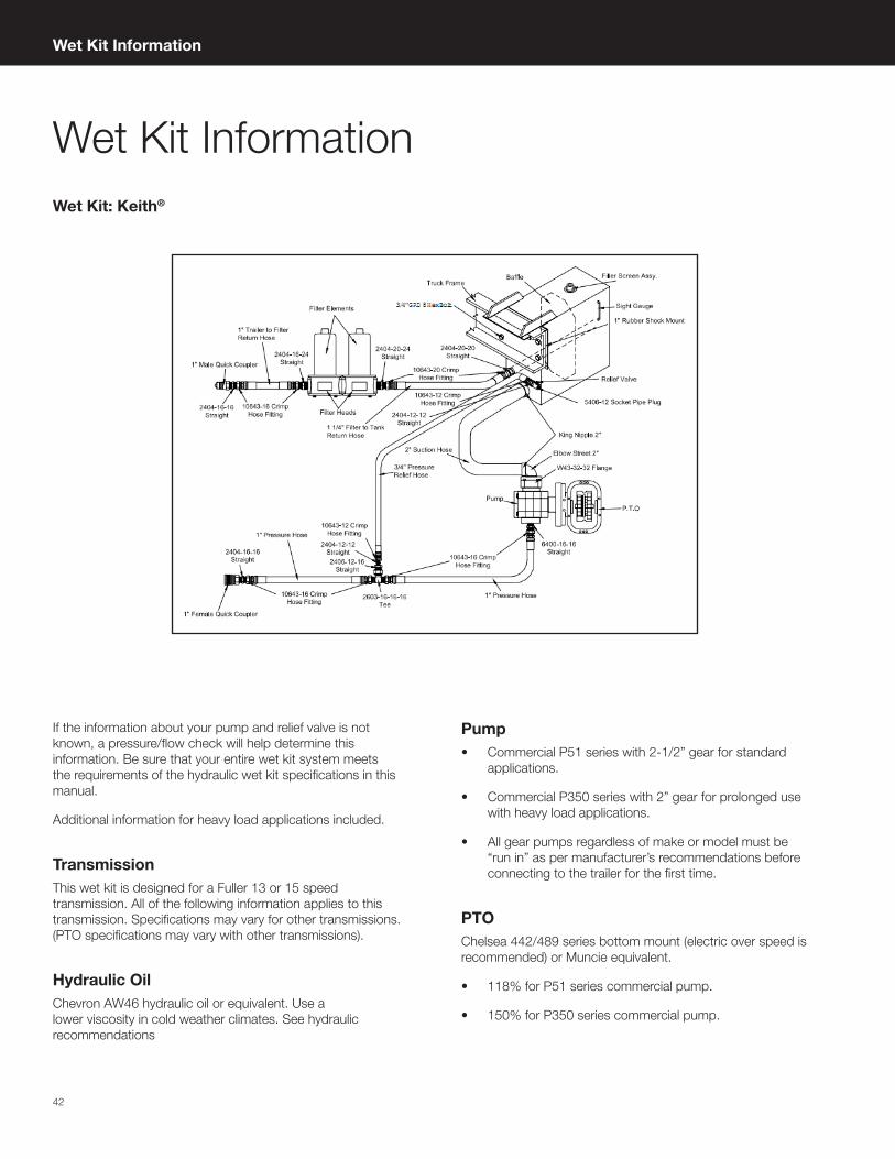
Pump• Commercial P51 series with 2-1/2” gear for standard
applications.
• Commercial P350 series with 2” gear for prolonged use with heavy load applications.
• All gear pumps regardless of make or model must be “run in” as per manufacturer’s recommendations before connecting to the trailer for the first time.
PTOChelsea 442/489 series bottom mount (electric over speed is recommended) or Muncie equivalent.
• 118% for P51 series commercial pump.
• 150% for P350 series commercial pump.
If the information about your pump and relief valve is not known, a pressure/flow check will help determine this information. Be sure that your entire wet kit system meets the requirements of the hydraulic wet kit specifications in this manual.
Additional information for heavy load applications included.
TransmissionThis wet kit is designed for a Fuller 13 or 15 speed transmission. All of the following information applies to this transmission. Specifications may vary for other transmissions. (PTO specifications may vary with other transmissions).
Hydraulic OilChevron AW46 hydraulic oil or equivalent. Use a lower viscosity in cold weather climates. See hydraulic recommendations
Wet Kit InformationWet Kit: Keith®
Operator’s Manual | Moving Floor Trailer 43
Wet Kit Information
Hydraulic ReservoirShould hold approximately 1 US gallon (3.8 L) of oil for every gallon per minute of pump output. A 40 US gpm pump should have a minimum 40 US gallon (150 L) reservoir.
Return Filter• Should be 10 to 30 micron return line filter.
• Zinga MF 2215-25-0-2-V-13 or equivalent with LE-10 or LE-30 elements or equivalent.
• Filter must be mounted as close to the reservoir as possible.
• Filter elements must be changed after 6 hours initially and every 6 months thereafter.
Hydraulic Lines
Pressure Return Suction
SAE 100R12 spec. SAE 100R1 spec.SAE 100R4 spec. or equivalent
1” (-16)
Trailer to filter: 1” (-16)
Filter to Tank:1-1/4” (-20).
2” ID, not more than 5” long
Pressure Relief ValveMust be a pilot operated type and sized correctly for the system. Sun Hydraulics RPGC-LAN-CAM or equivalent recommended. The tractor wet kit must be able to provide a minimum of 3000 psi, set relief pressure to 3000 psi (206 Bar).
Moving Floor Hydraulic Start-Up Checklist Before starting your floor, verify the following:
1. System is plumbed correctly using the plumbing diagram as a guide.
2. The minimum pump requirement is 110-190 L/min (29-50 gpm) at 220 bar (3200 psi).
3. Relief valve is set to 206 bar (3000 psi).
4. Oil is in the reservoir.
5. The PTO is engaged.
6. Quick disconnects are compatible and are completely engaged.
7. Operation handle is in the neutral position.
8. The pressure and return lines are connected correctly from the tractor to the trailer.
Hydraulic Recommendations
Temperature Range and Hydraulic Oil
Between -25 and 0 °C (-13 and 32 °F)
Between -15 and 30 °C (5 and 86 °F)
Between 15 and 40 °C (59 and 104 °F)
ISO 22 ISO 32 ISO 46
NOTICE
The suggested maximum viscosity value for start-up is 1000 cSt.
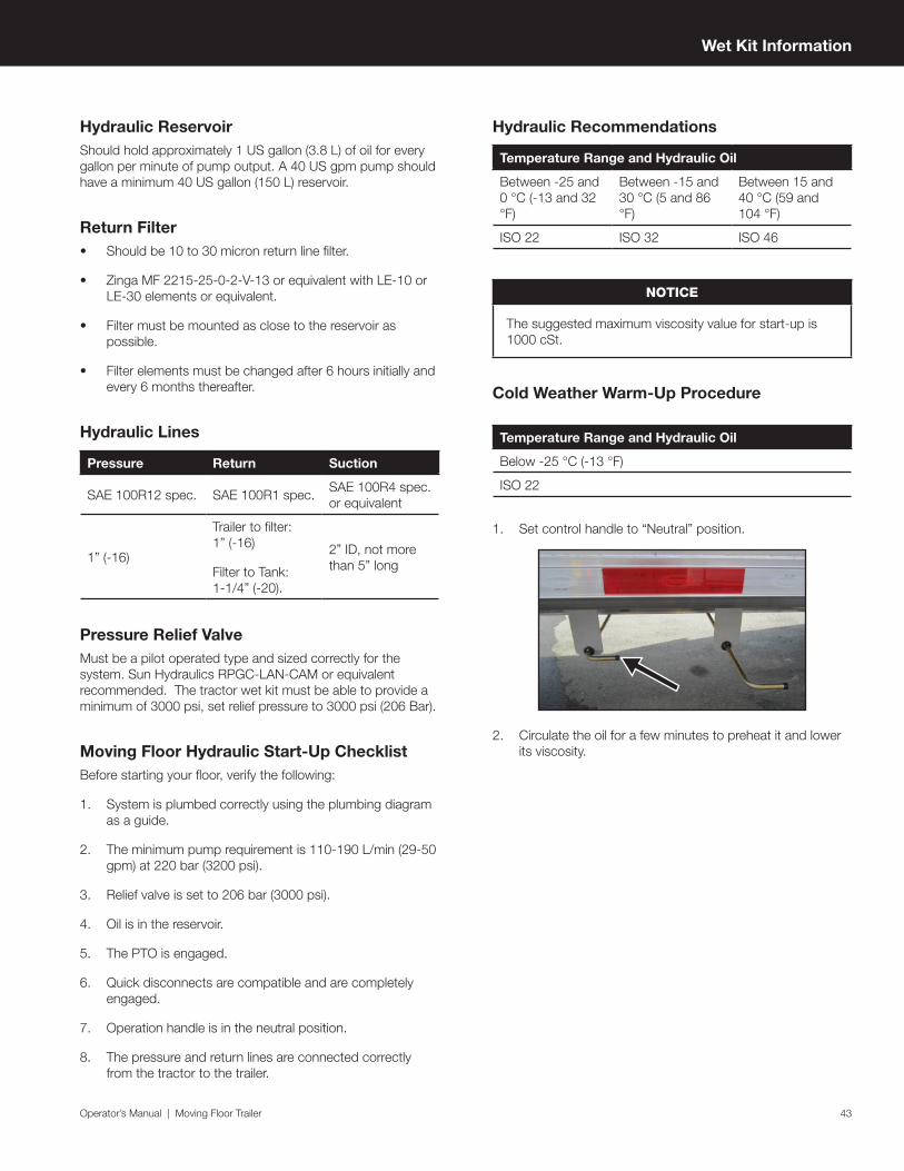
Cold Weather Warm-Up Procedure
Temperature Range and Hydraulic Oil
Below -25 °C (-13 °F)
ISO 22
1. Set control handle to “Neutral” position.
2. Circulate the oil for a few minutes to preheat it and lower its viscosity.

44
Schematics
Schematics
Service
Emergency
Brakes Emergency
Brakes Service
Air Bags
Ride Height Road Side
Ride Height Curb Side
Legend
Refer to the online version of this manual on the TYCROP Transport Solutions website for full colour schematics.

Operator’s Manual | Moving Floor Trailer 45
Schematics
Air
Sys
tem
Sch
emat
icD
raw
ing
No.
110
4-18
73 |
Rev
isio
n 08
SERV
ICE
GLA
DHAN
D
EMER
GEN
CYG
LADH
AND
RESERVOIR TANK
ACCESSORY TANK
ECU TANK
SPRING TANK
FRO
NT
VIEW
ECU
BOTT
OM
VIE
WEC
U
BACK
VIE
WEC
U
(REF
) SPR
ING
BRA
KE T
YPIC
AL
3/8"
1/2"
3/8"
3/8"
3/8"
1/2"
1/2"
32
44
41
6 2626
27
30 30
39
30
44
31
5 43
6
26
45
32
TO AIR BAGS
54
SPRI
NG
VAL
VE
FRO
NT
VIEW
SPRI
NG
VAL
VE
TOP
VIEW
20
DRAI
N C
OCK
TYP
ICAL
O
N A
LL T
ANK
BOTT
OM
S
1/4"ANTI COMPOUND
342
PORT
DET
AIL
TYPI
CAL
ALL
BRAK
E CH
AMBE
RS
32
48
FRO
NT
ROAD
SIDE
REF
ON
LY11
04-1
872
TAN
K AI
R 14
25CU
IN T
OP
MN
T
REF
ON
LY11
04-1
872
TAN
K AI
R 14
25CU
IN T
OP
MN
T
REF
ON
LY11
04-1
872
TAN
K AI
R 14
25CU
IN T
OP
MN
T
1/2"
34
19
40
19
35
47
47
ECU
SH
OW
N F
OR
REF
ON
LY64
2040
29 IF
TRA
ILER
NO
T EQ
UIP
ED W
ITH
LIF
T AX
LES
0000
-799
8 IF
TRA
ILER
EQ
UIP
ED W
ITH
LIF
T AX
LES
239
18"
BOLT
TO
PS
CHAS
SIS
NEA
R FR
ON
T.H
OLE
S BU
RNED
749
4938
29
28
6
18
46
27
1
27SE
E N
OTE
1
TO LIFT AXLE OR PLUG

46
Schematics
Rid
e H
eig
ht S
chem
atic
Dra
win
g N
o. 1
104-
2761
| R
evis
ion
02
LEVE
LIN
G VA
LVE
INST
ALL
ON
CEN
TER
OF
AXLE
#2
613
613
136 6
136
13
6
7
14
EXH
7
7
7
4
4
9 2X
15
EXHU
AST
22X
AIR
SPRI
NG
CON
TRO
L VA
LVE
TO A
CCES
SORY
TAN
K
3
1
TO ACCESSORY TANKDRIVER SIDE
AXLE
#1
AXLE
#2
AXLE
#3
AIR
BAGS
(REF
ON
LY)
TO A
IR S
CALE
TO D
UAL
AIR
SCA
LEIF
EQ
UIP
PED
NOTES:
ALL
AIR
BRA
KE T
UBIN
G S
YNFL
EX 3
250-
06 S
AE
J844
TYP
E B
1.N
YLO
N 1
1 (3
/8" O
D) B
LAC
K.
AIR
BRA
KE T
UBIN
G M
UST
BE A
RRA
NG
ED T
O E
LIM
INA
TE2.
ELBO
WS,
CLO
SE B
END
S, R
EDUC
ER F
ITTIN
GS,
UN
NEC
ESSA
RYLI
NE
LEN
GTH
S, W
HERE
PO
SSIB
LE.
MA
XIM
UM R
ECO
MM
END
ED A
IR B
RAKE
SYS
TEM
PRE
SSUR
E
3.IS
125
PSI
.
ALL
HO
SES
3/8"
UN
LESS
NO
TED
OTH
ERW
ISE
4.
Operator’s Manual | Moving Floor Trailer 47
Schematics
Lift
Axl
e S
chem
atic
Dra
win
g N
o. 1
105-
5292
| R
evis
ion
05
FRO
NT R
OA
DSID
E
16
17
1838
18
16
18
16
LIFT
BAG
(REF
) TYP
AIR
BAG
(REF
.)
32
1618
16
25
25
37
18
16
AXLE
# 1
AXLE
# 2
AXLE
# 3
36
11
18
1313
1/4"
BRA
IDED
HO
SE00
01-3
972
APPR
OX
32.5
"
INFL
ATE/
DEFL
ATE
TYP.
4 L
OCA
TIO
NS
LEVE
LIN
G V
ALVE
PRES
SURE
SEN
SOR
MAN
UAL
OVE
RRID
E
TO E
CU(C
ABLE
A2)
TO E
XH.
33
18
20
11
TO A
CCES
SORY
TAN
K CE
NTE
R PO
RT
17
19
17
17
12LI
FT A
XLE
CON
TRO
L VA
LVE
SIDE
VIE
W
TO A
IR S
CALE 34
22
LIFT
AXL
E CO
NTR
OL
VALV
E RE
AR V
IEW
1100
-213
2 CA
BLE
CON
NEC
TS T
O T
HE
D2 C
ABLE
CO
MIN
G F
ROM
TH
E EC
U
2
1931
31
25
13 13
25
13
1/4"
BRA
IDED
HO
SE00
01-3
972
APPR
OX
32.5
"
1/4"
BRA
IDED
HO
SE00
01-3
972
APPR
OX
32.5
"
1/4"
BRA
IDED
HO
SE00
01-3
972
APPR
OX
32.5
"
18
37
36
2513
2513
25
31
1
13
25
TO A
CCES
SORY
TAN
K DS
PO
RT
39
40
41
42
TO D
UAL
AIR
SCA
LEIF
EQ
UIP
PED
NOTE
S:
ALL
AIR
BRAK
E TU
BIN
G S
YNFL
EX 3
250-
06 S
AE J8
44 T
YPE
B N
YLO
N 1
1 (3
/8"
1.O
D)
AIR
BRAK
E TU
BIN
G M
UST
BE
ARRA
NG
ED T
O E
LIM
INAT
E EL
BOW
S, C
LOSE
2.
BEN
DS, R
EDU
CER
FITT
ING
S, U
NN
ECES
SARY
LIN
E LE
NG
THS
WH
ERE
POSS
IBLE
MAX
IMU
M R
ECO
MM
ENDE
D AI
R BR
AKE
SYST
EM P
RESS
URE
IS 1
20 P
SI3.

48
Schematics
Hydraulic Layout
RET
UR
N L
INE
HA
RD
TU
BIN
G
PR
ESSU
RE
LIN
EH
AR
D T
UB
ING
RET
UR
N L
INE
HO
SE
PR
ESSU
RE
LIN
EH
OSE
TRA
CTO
R R
ETU
RN
CO
NN
ECTI
ON
LOC
ATE
D O
N T
HE
FRO
NT
PA
SSEN
GER
SID
E O
F TR
AIL
ER
TRA
CTO
R S
UP
PLY
CO
NN
ECTI
ON
LOC
ATE
D O
N T
HE
FRO
NT
DR
IVER
SID
E O
F TR
AIL
ER
LOC
ATI
ON
WIL
L D
EPEN
D O
N M
OV
ING
FLO
OR
TYP
E
TO R
ETU
RN
PO
RT
ON
DR
IVE
UN
IT
PR
ESSU
RE
SCA
LE
TO P
RES
SUR
E P
OR
T O
N D
RIV
E U
NIT
Operator’s Manual | Moving Floor Trailer 49
Schematics
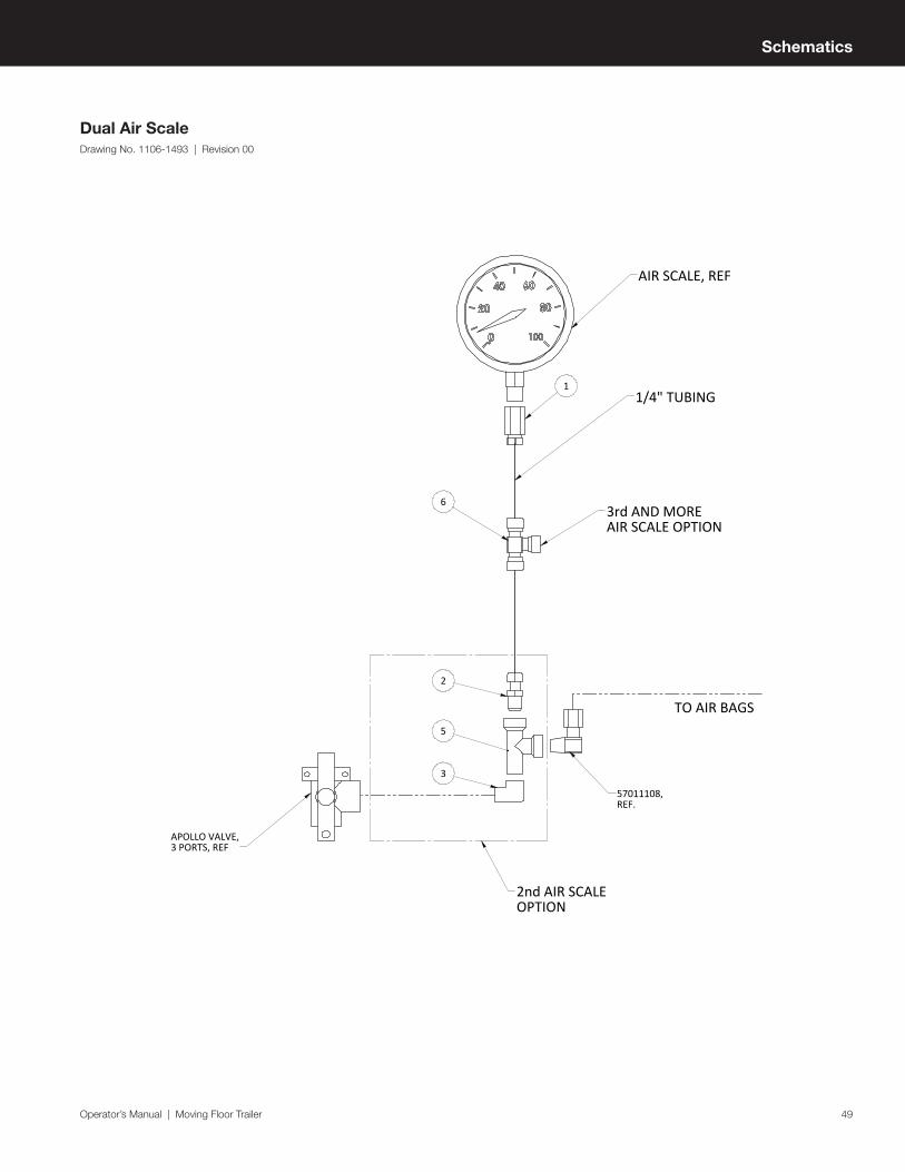
Dual Air ScaleDrawing No. 1106-1493 | Revision 00
11/4" TUBING
TO AIR BAGS
AIR SCALE, REF
57011108,REF.
3
5
2
APOLLO VALVE,3 PORTS, REF
2nd AIR SCALEOPTION
3rd AND MORE AIR SCALE OPTION
6

50
Parts OverviewFront Driver Side View
116 1097
8
51 2 3 4 116 1097
8
51 2 3 4
Item Description
1 Trailer
2 Hydraulics
3 Ladders
4 Platform
5 Landing Gear
6 Moving Floor
7 Air System
8 Tarp System
9 Fenders
10 Suspension & Wheel Ends
11 Decals
Parts Overview

Operator’s Manual | Moving Floor Trailer 51
Parts Overview - 10
Rear Passenger Side View
15
312 13 1114
15
312 13 1114
Item Description
12 Trailer Lighting
13 Doors
14 Bumper
3 Ladders
11 Decals
15 Kingpin
