2017 baja sae competition - university of houstoncot-mect4276.tech.uh.edu/~mhodekar/report2.pdf ·...
TRANSCRIPT
2017 Baja SAE Competition
MECT 4276 – Fall 2016
Senior Design I – Report II
November 29, 2016
Keith Hernandez
Team Lead
Enrique DeLeon
Mechanical Lead
Manjula Hodekar
Logistics Lead
Team Xtreme
2
Table of Contents
Introduction 3
Team Objective 3
Deliverables 3
History 4
Event Categories 5
Dynamic Events 5
Static Event 6
Previous Winners 8
Winning Strategy 9
Major Components 9
Chassis 10
Suspension 18
Engine 24
Drivetrain 24
Steering 26
Project Management 29
Budget 29
Timeline 30
Work Breakdown Structure 30
Risk Matrix 31
References 32
Appendix 34
Timeline 35
Gantt Chart 36
Inventory 37
Weld Testing 38
Sponsorship Brochure 41
Team Xtreme
3
Introduction
The Baja SAE Competition is one of the design series offered by the Society of Automotive
Engineers (SAE) that University students from around the world can compete in. University
students are required to design and fabricate a high performance off road vehicle. The
competition is a real world scenario that lets students demonstrate their knowledge in the design
and fabrication of a dynamic mechanism. The Baja SAE Competition has a long list of rules and
regulations to ensure the safety of all participants however students are allowed to use creative
and critical thinking to design their vehicle in an innovative fashion. The main focus of the Baja
SAE challenge is to promote teamwork and project management skills between team members.
These qualities become a key to producing a successful project.
Team Objective
The objective is to design and build a vehicle that meets the rules and regulations of the 2017
Baja SAE competition. Team Xtreme will represent the University of Houston and participate in
the competition that will take place in Pittsburg, Kansas on May 25-28, 2017.
Deliverables
Register for the 2017 Baja competition in Pittsburg, Kansas by the November 14, 2016
deadline
Have a Baja vehicle that is mechanically complete with a functioning suspension assembled
by December 2016
Manufacture carbon fiber uprights for the suspension
Achieve a vehicle weight under 400 lbs.
Team Xtreme
4
Pass the Baja SAE inspection for the competition
Achieve a top speed of 30 mph on a flat surface
Design a vehicle that can achieve a flat jump of 7 ft.
Implement instrumentation that is capable of data acquisition
The deliverables were approved by Professor Raresh Pascali and are intended to be met by May
2017. One important note is that in order to meet the second deliverable and have a vehicle that
is mechanically complete with a functioning suspension assembled by December 2016, Team
Xtreme will be using some of the components that were designed and fabricated by the Baja
Brigade senior design team.
History
The first Baja SAE Competition was held in 1976 at the University of South Carolina in Jackson,
SC. Ten teams registered for this event with ninety students participating. The competition was
eventually divided into 3 regions: East, Midwest, and West. In 1978, the first Midwest and West
regions competition was held in Milwaukee, WI, Arizona state university, and Phoenix, AZ
respectively. The number of teams that participated continued to grow every year after the first
event. By 2016, 100 teams registered with more than 1000 students participating in all three
regions. Over the years, the Baja SAE Competition has spread to other countries outside of
North America. Brazil’s first Baja SAE event was held in 1995 with 10 registered teams and 90
participating students. Korea’s first event was hosted by Yeungnam University in 1996 with 10
teams and 280 students. South Africa’s first event also started in 1996, hosted by the University
of Pretoria with 4 teams and 12 students.
Team Xtreme
5
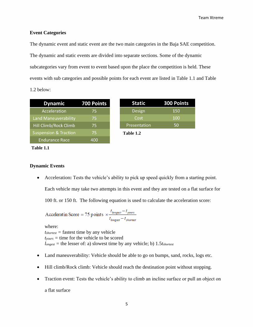
Event Categories
The dynamic event and static event are the two main categories in the Baja SAE competition.
The dynamic and static events are divided into separate sections. Some of the dynamic
subcategories vary from event to event based upon the place the competition is held. These
events with sub categories and possible points for each event are listed in Table 1.1 and Table
1.2 below:
Dynamic Events
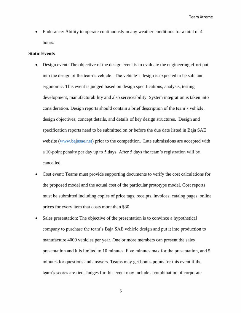
Acceleration: Tests the vehicle’s ability to pick up speed quickly from a starting point.
Each vehicle may take two attempts in this event and they are tested on a flat surface for
100 ft. or 150 ft. The following equation is used to calculate the acceleration score:
where:
tshortest = fastest time by any vehicle
tyours = time for the vehicle to be scored
longest = the lesser of: a) slowest time by any vehicle; b) 1.5tshortest
Land maneuverability: Vehicle should be able to go on bumps, sand, rocks, logs etc.
Hill climb/Rock climb: Vehicle should reach the destination point without stopping.
Traction event: Tests the vehicle’s ability to climb an incline surface or pull an object on
a flat surface
Table 1.1
Table 1.2
Team Xtreme
6
Endurance: Ability to operate continuously in any weather conditions for a total of 4
hours.
Static Events
Design event: The objective of the design event is to evaluate the engineering effort put
into the design of the team’s vehicle. The vehicle’s design is expected to be safe and
ergonomic. This event is judged based on design specifications, analysis, testing
development, manufacturability and also serviceability. System integration is taken into
consideration. Design reports should contain a brief description of the team’s vehicle,
design objectives, concept details, and details of key design structures. Design and
specification reports need to be submitted on or before the due date listed in Baja SAE
website (www.bajasae.net) prior to the competition. Late submissions are accepted with
a 10-point penalty per day up to 5 days. After 5 days the team’s registration will be
cancelled.
Cost event: Teams must provide supporting documents to verify the cost calculations for
the proposed model and the actual cost of the particular prototype model. Cost reports
must be submitted including copies of price tags, receipts, invoices, catalog pages, online
prices for every item that costs more than $30.
Sales presentation: The objective of the presentation is to convince a hypothetical
company to purchase the team’s Baja SAE vehicle design and put it into production to
manufacture 4000 vehicles per year. One or more members can present the sales
presentation and it is limited to 10 minutes. Five minutes max for the presentation, and 5
minutes for questions and answers. Teams may get bonus points for this event if the
team’s scores are tied. Judges for this event may include a combination of corporate
Team Xtreme
7
executives who may have experience in marketing, production and finance as well as
engineering.
Design event:
The design event consists of two parts: Design evaluation and the design report. The
design report needs to be submitted before the competition. It includes a brief description of the
vehicle, vehicle concepts, the team’s design objectives, and the details about important features.
The team should be able to provide backup data, analysis, and testing techniques as well as
documents on request at the competition. A design specification sheet needs to be prepared using
the standard template that can be found at www.bajasae.net/go/downloads and submitted
electronically in .xlsx file format.
Design judges will review the report and inspect the vehicle on site for evaluation.
Design reports consist of eight (8) pages of A4 size paper with up to four pages of text and three
pages of vehicle drawings showing the vehicle’s front view, top view, and side view. Photos can
be included in the optional page. One optional page is allowed for photos, charts, graphs, etc.
Design reports must be submitted electronically in pdf format as a single file. Note: late
submissions will result in a ten-point penalty per day up to five days.
The design event is judged based on the design report, and the inspection of the vehicle
on site. Teams are allowed to bring supporting material such as photographs, drawings, plans,
charts, and sample components or materials. One or more team members can present the design
presentation. The design presentation is limited to a total of ten minutes, including one minute
for the clarification questions from the judges, and any team member can answer the questions.
Teams are allowed to bring a laptop, binders or posters to show documentation of the
engineering work they have completed.
Team Xtreme
8
Cost event:
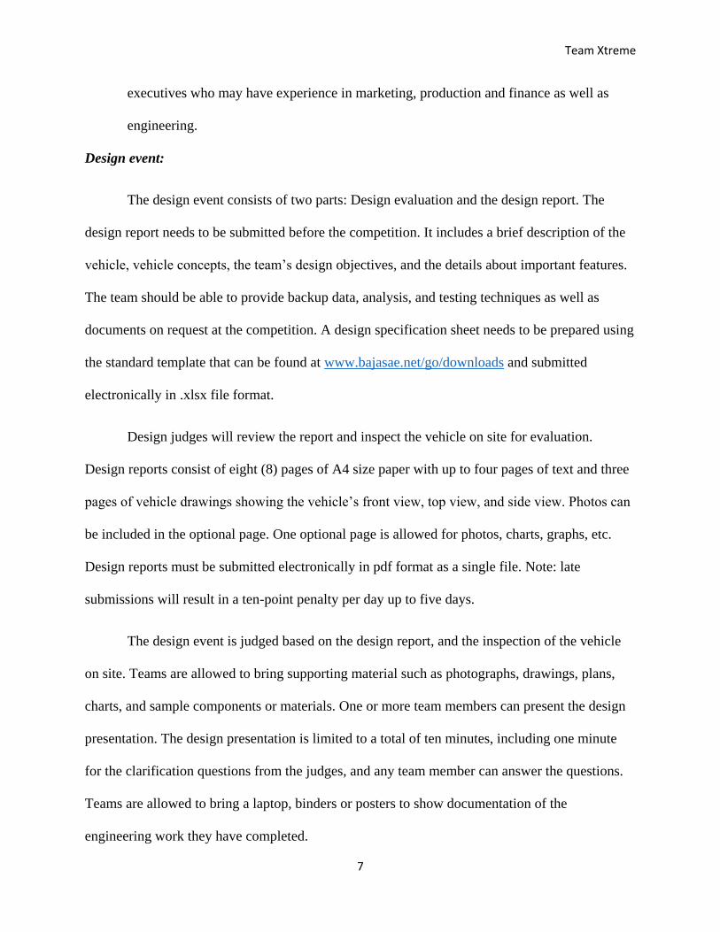
The cost event consists of two related sections, 1. Cost report and 2. Prototype cost. The
cost report includes the background information and calculations to verify the vehicle’s actual
cost. The prototype cost consists of the actual cost of the prototype. The cost report must contain
a one-page summery sheet and cost documentation including copies of price tags, receipts,
invoices, catalog pages, and online prices for every item that costs more than $30. Teams also
need to bring a hard copy of the cost report to the competition site. The prototype cost score will
be calculated using the following formula:
𝑃𝑟𝑜𝑡𝑜𝑡𝑦𝑝𝑒 𝐶𝑜𝑠𝑡 = 85 𝑝𝑜𝑖𝑛𝑡𝑠 x C max −Cyours
C max −𝐶𝑙𝑜𝑤
Where:
Cyours =Vehicle cost, as corrected
Clow = Lowest vehicle cost, corrected
Cmax = Highest Vehicle cost, as corrected
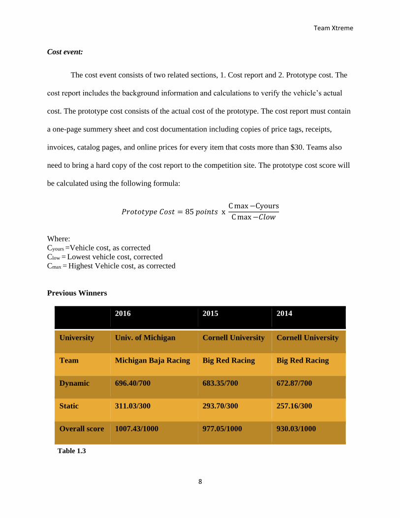
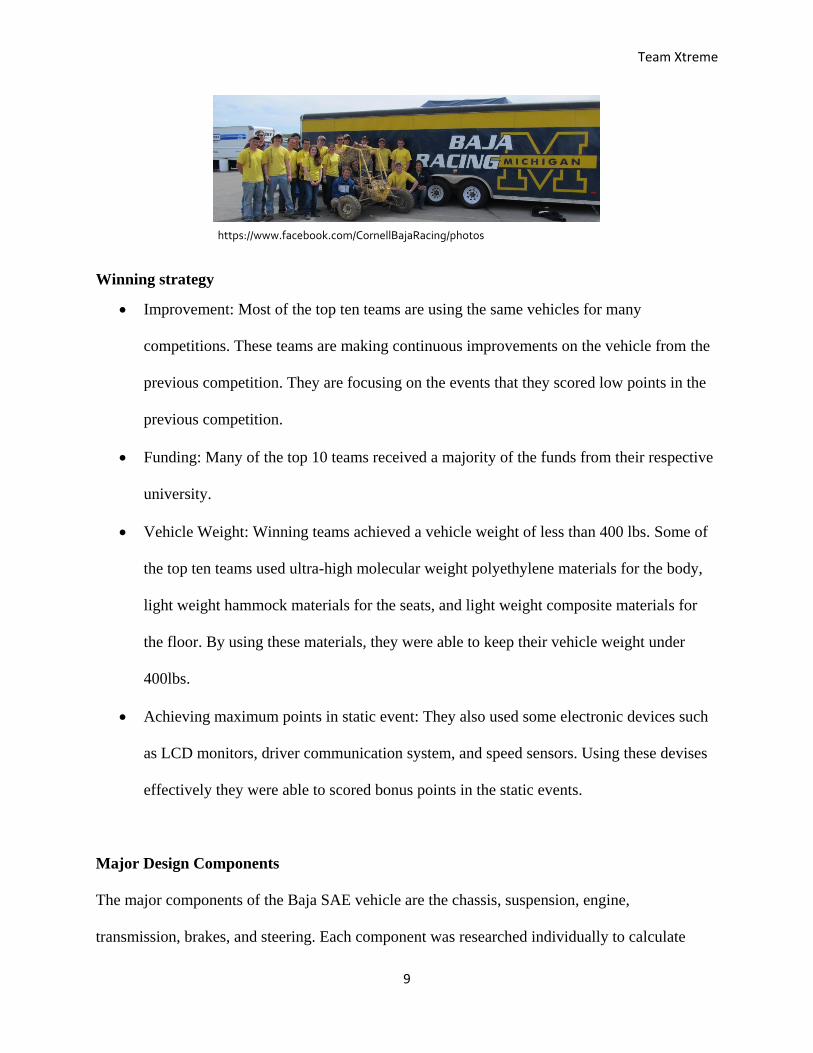
Previous Winners
2016 2015 2014
University Univ. of Michigan Cornell University Cornell University
Team Michigan Baja Racing Big Red Racing Big Red Racing
Dynamic 696.40/700 683.35/700 672.87/700
Static 311.03/300 293.70/300 257.16/300
Overall score 1007.43/1000 977.05/1000 930.03/1000
Table 1.3
Team Xtreme
9
Winning strategy
Improvement: Most of the top ten teams are using the same vehicles for many
competitions. These teams are making continuous improvements on the vehicle from the
previous competition. They are focusing on the events that they scored low points in the
previous competition.
Funding: Many of the top 10 teams received a majority of the funds from their respective
university.
Vehicle Weight: Winning teams achieved a vehicle weight of less than 400 lbs. Some of
the top ten teams used ultra-high molecular weight polyethylene materials for the body,
light weight hammock materials for the seats, and light weight composite materials for
the floor. By using these materials, they were able to keep their vehicle weight under
400lbs.
Achieving maximum points in static event: They also used some electronic devices such
as LCD monitors, driver communication system, and speed sensors. Using these devises
effectively they were able to scored bonus points in the static events.
Major Design Components
The major components of the Baja SAE vehicle are the chassis, suspension, engine,
transmission, brakes, and steering. Each component was researched individually to calculate
https://www.facebook.com/CornellBajaRacing/photos
Team Xtreme
10
costs, availability and standards used throughout other vehicles participating in the Baja SAE
competition.
Chassis
The chassis is a series of tubes connected together to form a coherent structure. The chassis
provides a rigid connection between the rear and front suspension and creates and overall
structural support for other necessary systems of the vehicle. The design of the chassis is
important to support the other components in their respective positions. It also serves as the base
of the entire vehicle. It is extremely important because it provides the necessary protection for
the driver if the vehicle is to receive a substantial amount off impact due to a crash or roll over.
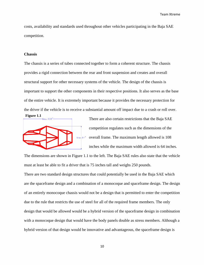
There are also certain restrictions that the Baja SAE
competition regulates such as the dimensions of the
overall frame. The maximum length allowed is 108
inches while the maximum width allowed is 64 inches.
The dimensions are shown in Figure 1.1 to the left. The Baja SAE rules also state that the vehicle
must at least be able to fit a driver that is 75 inches tall and weighs 250 pounds.
There are two standard design structures that could potentially be used in the Baja SAE which
are the spaceframe design and a combination of a monocoque and spaceframe design. The design
of an entirely monocoque chassis would not be a design that is permitted to enter the competition
due to the rule that restricts the use of steel for all of the required frame members. The only
design that would be allowed would be a hybrid version of the spaceframe design in combination
with a monocoque design that would have the body panels double as stress members. Although a
hybrid version of that design would be innovative and advantageous, the spaceframe design is
Figure 1.1
Figure 1.1
Team Xtreme
11
widely used for the vehicles that participate in the Baja SAE competition because of the ease of
fabrication of the structure and the ability to easily make modifications if needed.
In order to meet the deliverable of having a complete rolling chassis by the end of December
2016, under the approval of the instructor, the frame that was designed and fabricated by the
Baja Brigade senior design team will be completed by Team Xtreme. The team will complete the
welding on the frame and build on the design that was originally considered by the Baja Brigade
team. The team will reconsider the material and design in the second semester and make
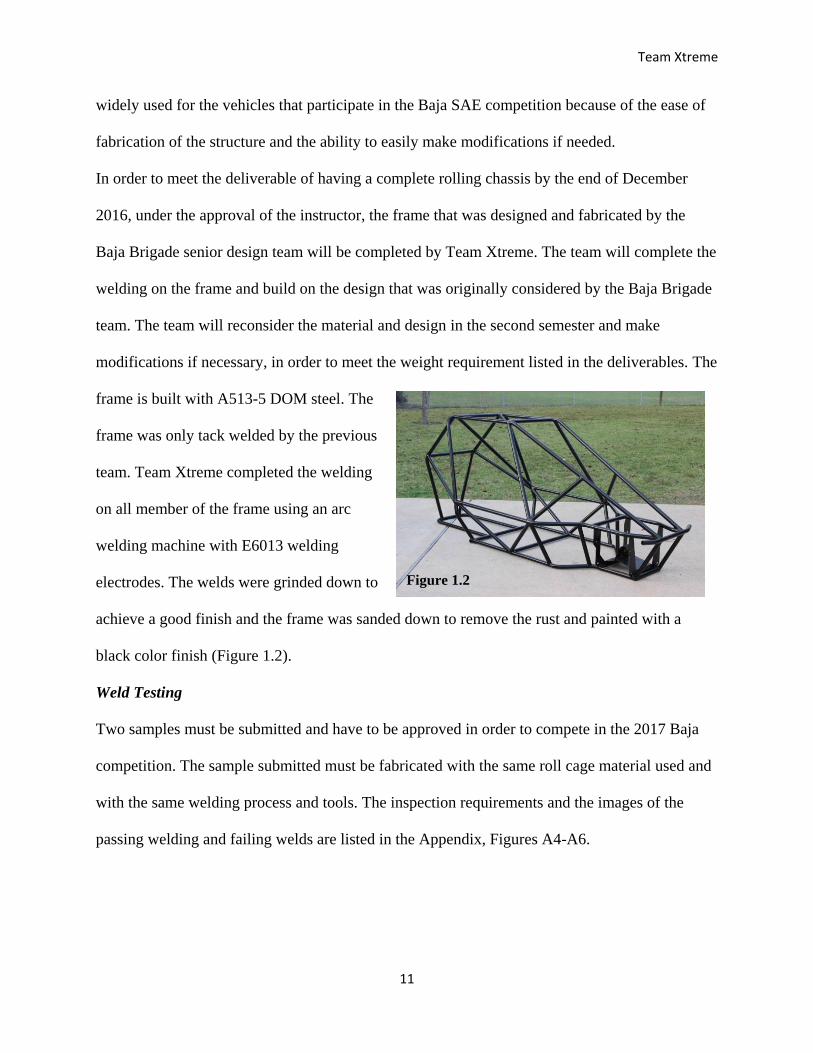
modifications if necessary, in order to meet the weight requirement listed in the deliverables. The
frame is built with A513-5 DOM steel. The
frame was only tack welded by the previous
team. Team Xtreme completed the welding
on all member of the frame using an arc
welding machine with E6013 welding
electrodes. The welds were grinded down to
achieve a good finish and the frame was sanded down to remove the rust and painted with a
black color finish (Figure 1.2).
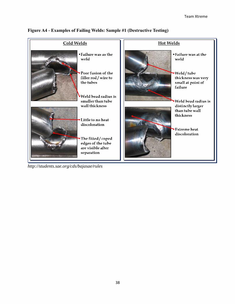
Weld Testing
Two samples must be submitted and have to be approved in order to compete in the 2017 Baja
competition. The sample submitted must be fabricated with the same roll cage material used and
with the same welding process and tools. The inspection requirements and the images of the
passing welding and failing welds are listed in the Appendix, Figures A4-A6.
Figure 1.2
Team Xtreme
12
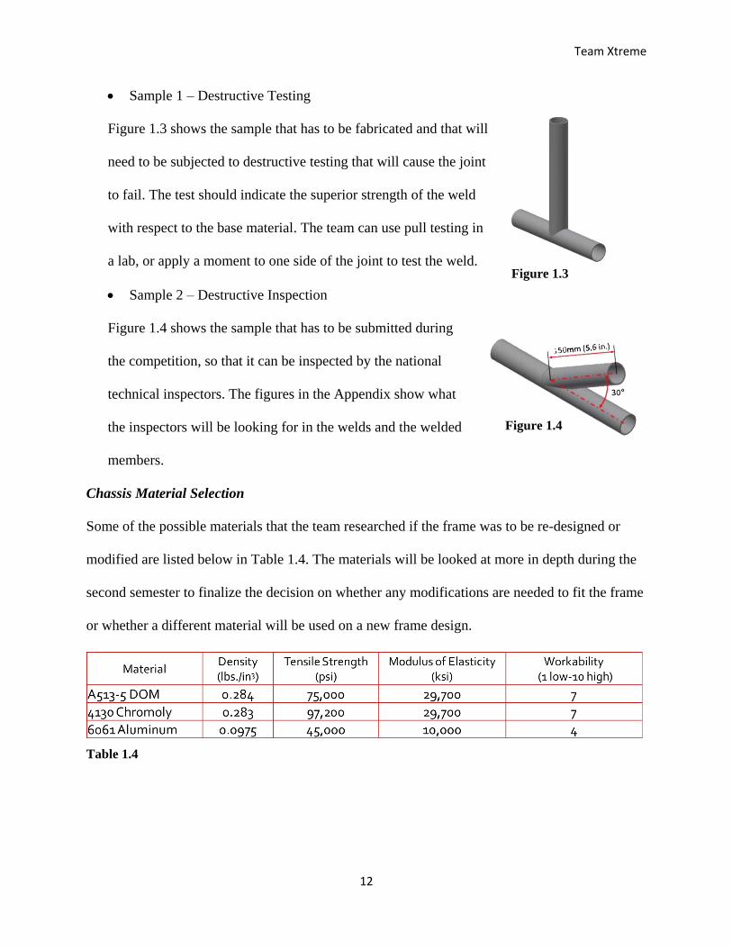
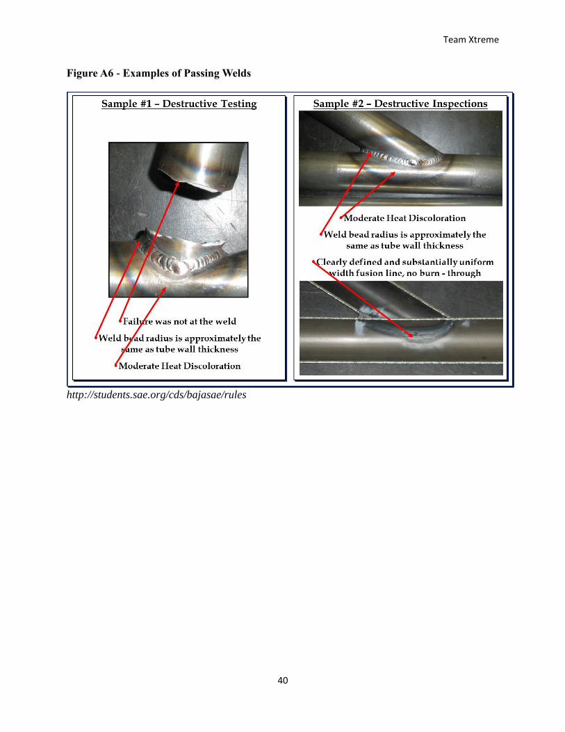
Sample 1 – Destructive Testing
Figure 1.3 shows the sample that has to be fabricated and that will
need to be subjected to destructive testing that will cause the joint
to fail. The test should indicate the superior strength of the weld
with respect to the base material. The team can use pull testing in
a lab, or apply a moment to one side of the joint to test the weld.
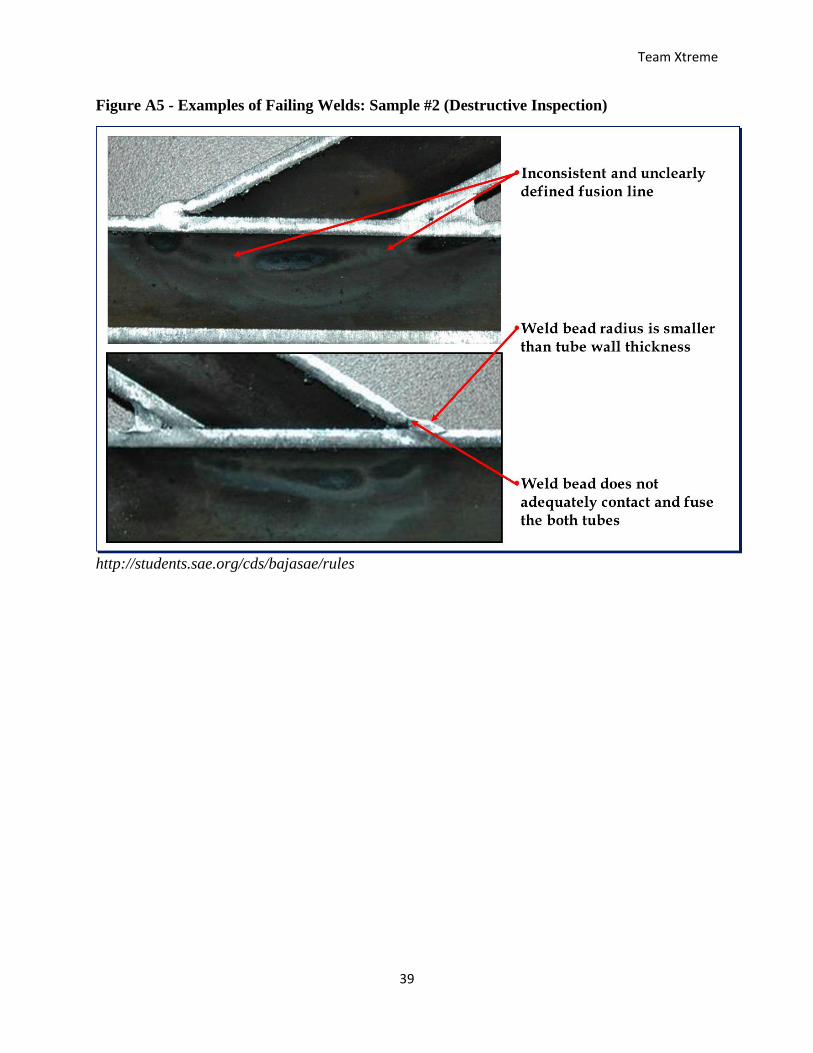
Sample 2 – Destructive Inspection
Figure 1.4 shows the sample that has to be submitted during
the competition, so that it can be inspected by the national
technical inspectors. The figures in the Appendix show what
the inspectors will be looking for in the welds and the welded
members.
Chassis Material Selection
Some of the possible materials that the team researched if the frame was to be re-designed or
modified are listed below in Table 1.4. The materials will be looked at more in depth during the
second semester to finalize the decision on whether any modifications are needed to fit the frame
or whether a different material will be used on a new frame design.
Table 1.4
Figure 1.3
Figure 1.4
Team Xtreme
13
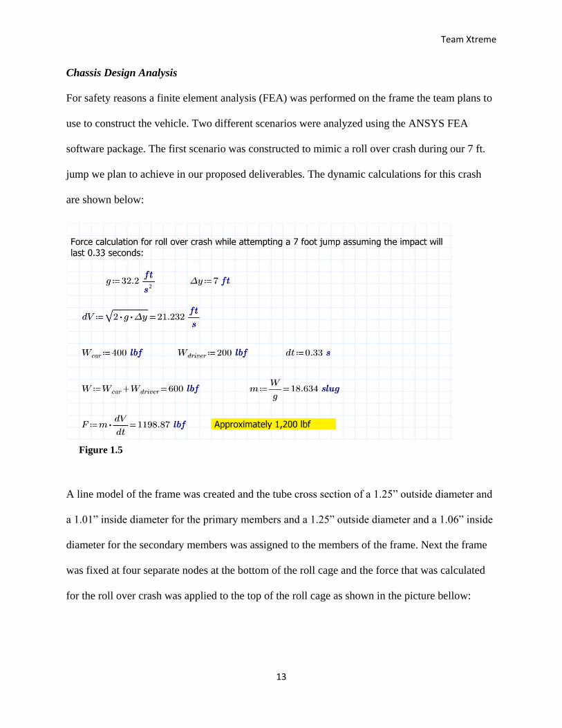
Chassis Design Analysis
For safety reasons a finite element analysis (FEA) was performed on the frame the team plans to
use to construct the vehicle. Two different scenarios were analyzed using the ANSYS FEA
software package. The first scenario was constructed to mimic a roll over crash during our 7 ft.
jump we plan to achieve in our proposed deliverables. The dynamic calculations for this crash
are shown below:
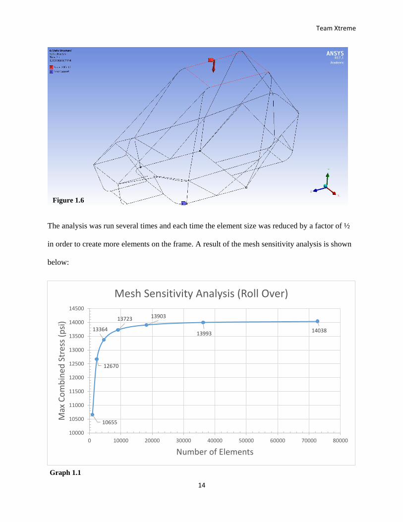
A line model of the frame was created and the tube cross section of a 1.25” outside diameter and
a 1.01” inside diameter for the primary members and a 1.25” outside diameter and a 1.06” inside
diameter for the secondary members was assigned to the members of the frame. Next the frame
was fixed at four separate nodes at the bottom of the roll cage and the force that was calculated
for the roll over crash was applied to the top of the roll cage as shown in the picture bellow:
Figure 1.5
Team Xtreme
14
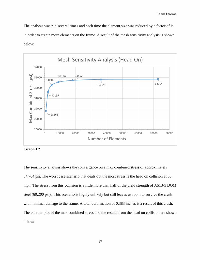
The analysis was run several times and each time the element size was reduced by a factor of ½
in order to create more elements on the frame. A result of the mesh sensitivity analysis is shown
below:
10655
12670
13364
13723 13903
1399314038
10000
10500
11000
11500
12000
12500
13000
13500
14000
14500
0 10000 20000 30000 40000 50000 60000 70000 80000
Max
Co
mb
ined
Str
ess
(psi
)
Number of Elements
Mesh Sensitivity Analysis (Roll Over)
Figure 1.6
Graph 1.1
Team Xtreme
15
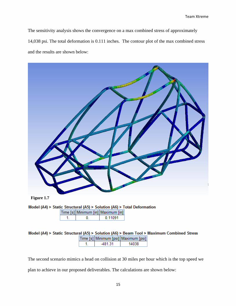
The sensitivity analysis shows the convergence on a max combined stress of approximately
14,038 psi. The total deformation is 0.111 inches. The contour plot of the max combined stress
and the results are shown below:
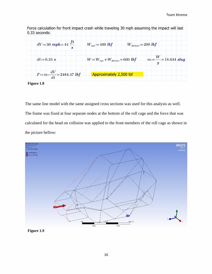
The second scenario mimics a head on collision at 30 miles per hour which is the top speed we
plan to achieve in our proposed deliverables. The calculations are shown below:
Figure 1.7
Team Xtreme
16
The same line model with the same assigned cross sections was used for this analysis as well.
The frame was fixed at four separate nodes at the bottom of the roll cage and the force that was
calculated for the head on collision was applied to the front members of the roll cage as shown in
the picture bellow:
Figure 1.8
Figure 1.9
Team Xtreme
17
The analysis was run several times and each time the element size was reduced by a factor of ½
in order to create more elements on the frame. A result of the mesh sensitivity analysis is shown
below:
The sensitivity analysis shows the convergence on a max combined stress of approximately
34,704 psi. The worst case scenario that deals out the most stress is the head on collision at 30
mph. The stress from this collision is a little more than half of the yield strength of A513-5 DOM
steel (60,200 psi). This scenario is highly unlikely but still leaves us room to survive the crash
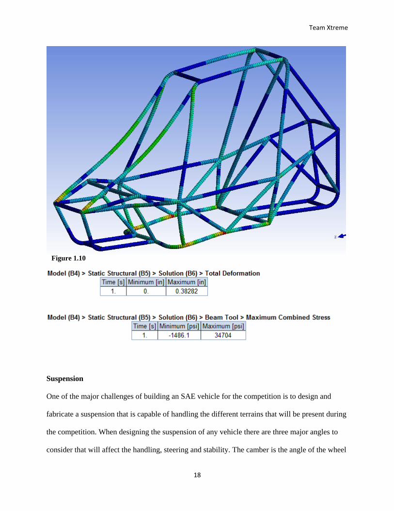
with minimal damage to the frame. A total deformation of 0.383 inches is a result of this crash.
The contour plot of the max combined stress and the results from the head on collision are shown
below:
28568
32199
3349434140 34462
34623 34704
25000
27000
29000
31000
33000
35000
37000
0 10000 20000 30000 40000 50000 60000 70000 80000
Max
Co
mb
ined
Str
ess
(psi
)
Number of Elements
Mesh Sensitivity Analysis (Head On)
Graph 1.2
Team Xtreme
18
Suspension
One of the major challenges of building an SAE vehicle for the competition is to design and
fabricate a suspension that is capable of handling the different terrains that will be present during
the competition. When designing the suspension of any vehicle there are three major angles to
consider that will affect the handling, steering and stability. The camber is the angle of the wheel
Figure 1.10
Team Xtreme
19
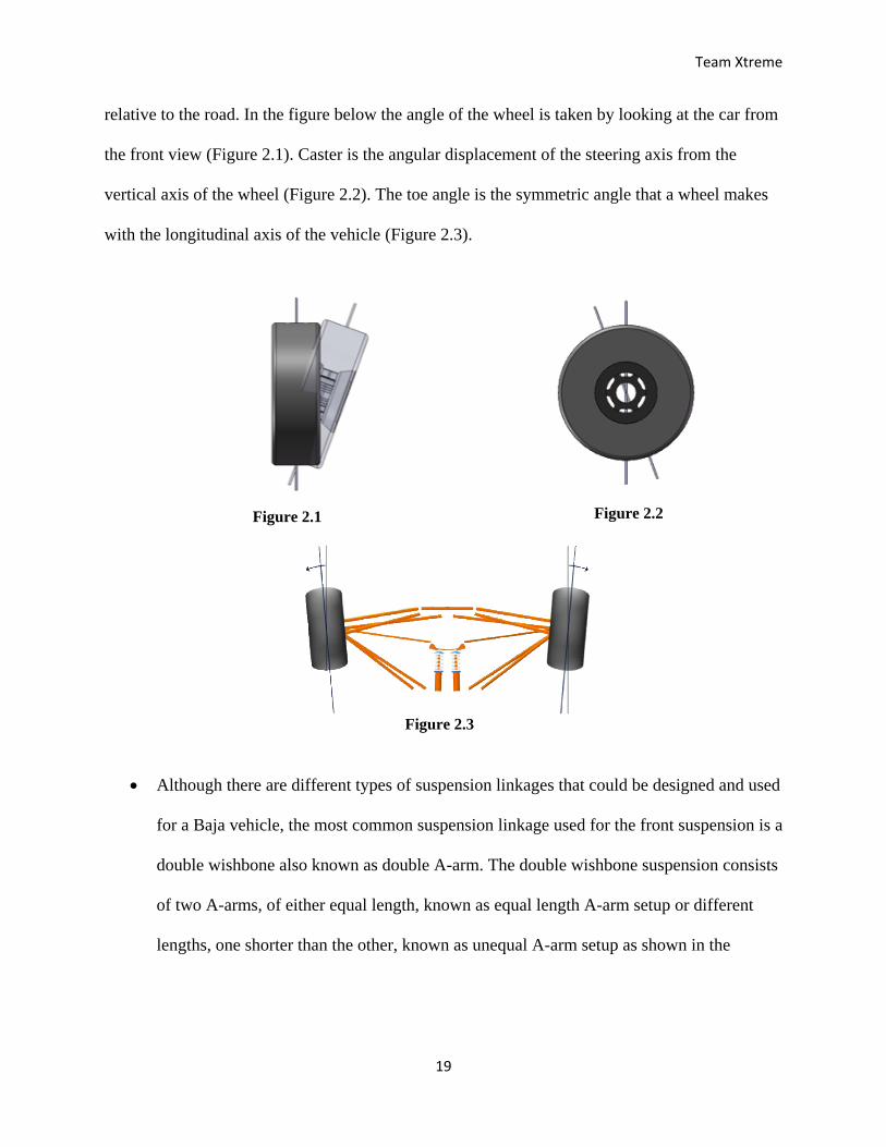
relative to the road. In the figure below the angle of the wheel is taken by looking at the car from
the front view (Figure 2.1). Caster is the angular displacement of the steering axis from the
vertical axis of the wheel (Figure 2.2). The toe angle is the symmetric angle that a wheel makes
with the longitudinal axis of the vehicle (Figure 2.3).
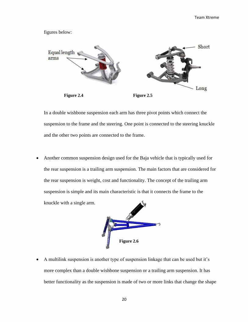
Although there are different types of suspension linkages that could be designed and used
for a Baja vehicle, the most common suspension linkage used for the front suspension is a
double wishbone also known as double A-arm. The double wishbone suspension consists
of two A-arms, of either equal length, known as equal length A-arm setup or different
lengths, one shorter than the other, known as unequal A-arm setup as shown in the
Figure 2.1 Figure 2.2
Figure 2.3
Team Xtreme
20
figures below:
In a double wishbone suspension each arm has three pivot points which connect the
suspension to the frame and the steering. One point is connected to the steering knuckle
and the other two points are connected to the frame.
Another common suspension design used for the Baja vehicle that is typically used for
the rear suspension is a trailing arm suspension. The main factors that are considered for
the rear suspension is weight, cost and functionality. The concept of the trailing arm
suspension is simple and its main characteristic is that it connects the frame to the
knuckle with a single arm.
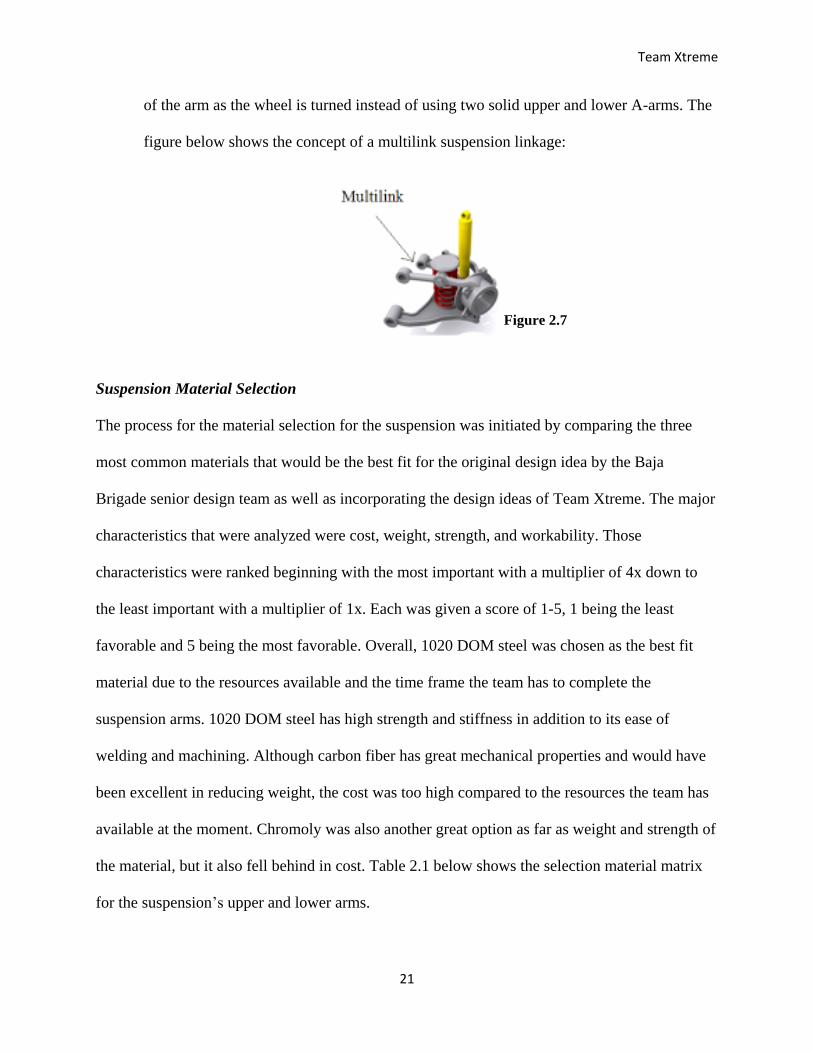
A multilink suspension is another type of suspension linkage that can be used but it’s
more complex than a double wishbone suspension or a trailing arm suspension. It has
better functionality as the suspension is made of two or more links that change the shape
Figure 2.6
Figure 2.4 Figure 2.5
Team Xtreme
21
of the arm as the wheel is turned instead of using two solid upper and lower A-arms. The
figure below shows the concept of a multilink suspension linkage:
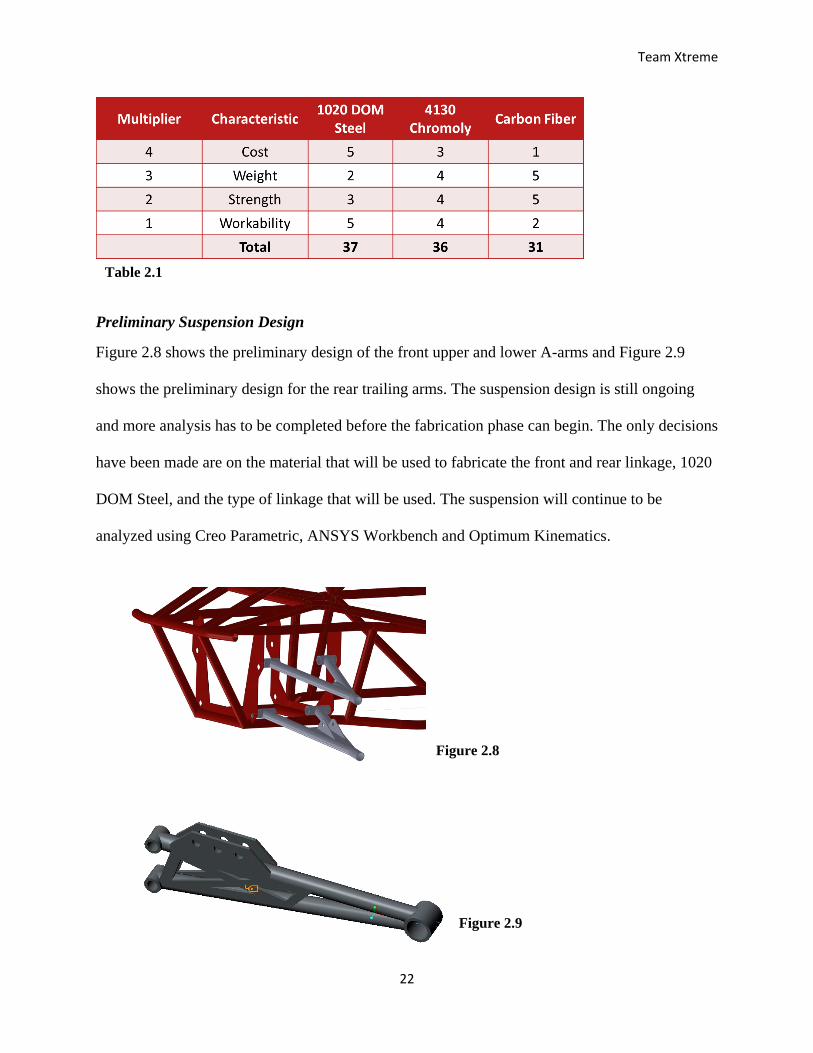
Suspension Material Selection
The process for the material selection for the suspension was initiated by comparing the three
most common materials that would be the best fit for the original design idea by the Baja
Brigade senior design team as well as incorporating the design ideas of Team Xtreme. The major
characteristics that were analyzed were cost, weight, strength, and workability. Those
characteristics were ranked beginning with the most important with a multiplier of 4x down to
the least important with a multiplier of 1x. Each was given a score of 1-5, 1 being the least
favorable and 5 being the most favorable. Overall, 1020 DOM steel was chosen as the best fit
material due to the resources available and the time frame the team has to complete the
suspension arms. 1020 DOM steel has high strength and stiffness in addition to its ease of
welding and machining. Although carbon fiber has great mechanical properties and would have
been excellent in reducing weight, the cost was too high compared to the resources the team has
available at the moment. Chromoly was also another great option as far as weight and strength of
the material, but it also fell behind in cost. Table 2.1 below shows the selection material matrix
for the suspension’s upper and lower arms.
Figure 2.7
Team Xtreme
22
Preliminary Suspension Design
Figure 2.8 shows the preliminary design of the front upper and lower A-arms and Figure 2.9
shows the preliminary design for the rear trailing arms. The suspension design is still ongoing
and more analysis has to be completed before the fabrication phase can begin. The only decisions
have been made are on the material that will be used to fabricate the front and rear linkage, 1020
DOM Steel, and the type of linkage that will be used. The suspension will continue to be
analyzed using Creo Parametric, ANSYS Workbench and Optimum Kinematics.
Table 2.1
Figure 2.8
Figure 2.9
Team Xtreme
23
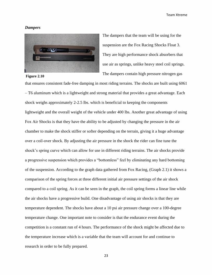
Dampers
The dampers that the team will be using for the
suspension are the Fox Racing Shocks Float 3.
They are high performance shock absorbers that
use air as springs, unlike heavy steel coil springs.
The dampers contain high pressure nitrogen gas
that ensures consistent fade-free damping in most riding terrains. The shocks are built using 6061
– T6 aluminum which is a lightweight and strong material that provides a great advantage. Each
shock weighs approximately 2-2.5 lbs. which is beneficial to keeping the components
lightweight and the overall weight of the vehicle under 400 lbs. Another great advantage of using
Fox Air Shocks is that they have the ability to be adjusted by changing the pressure in the air
chamber to make the shock stiffer or softer depending on the terrain, giving it a huge advantage
over a coil-over shock. By adjusting the air pressure in the shock the rider can fine tune the
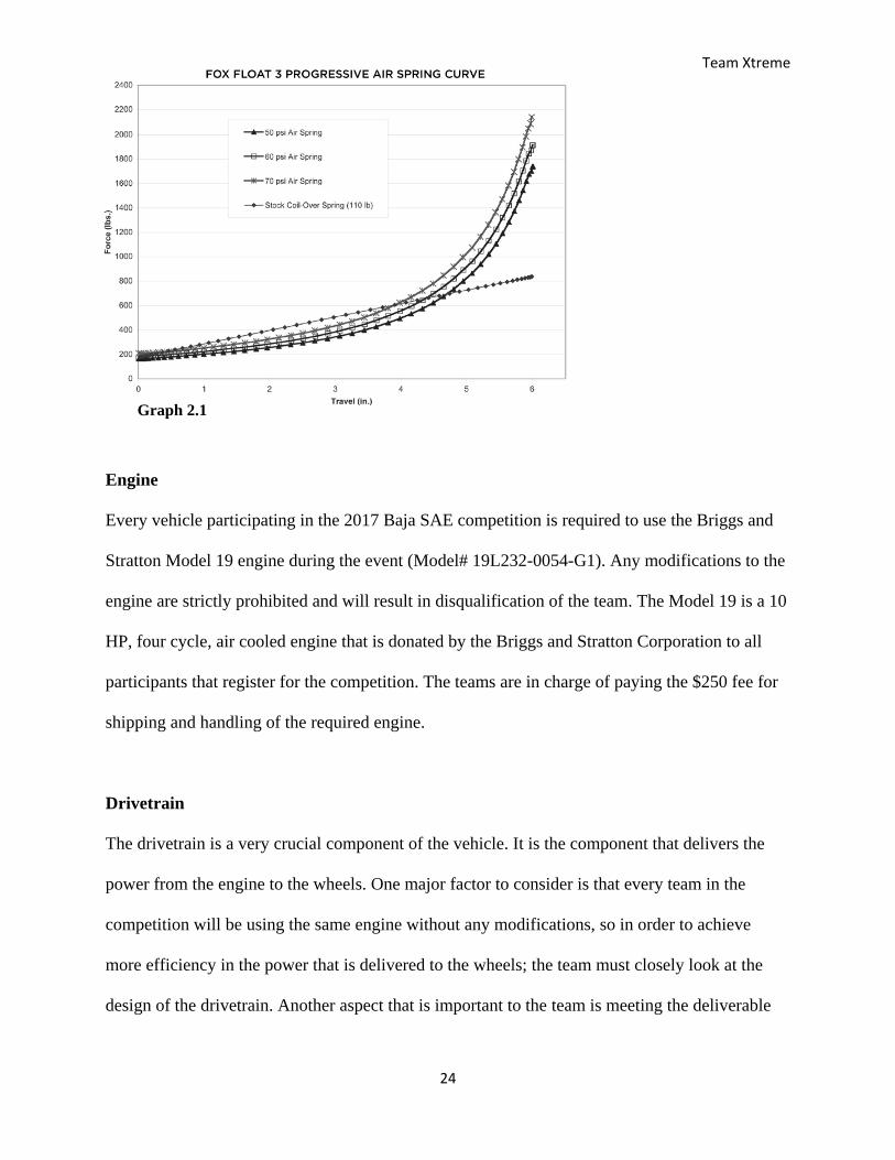
shock’s spring curve which can allow for use in different riding terrains. The air shocks provide
a progressive suspension which provides a “bottomless” feel by eliminating any hard bottoming
of the suspension. According to the graph data gathered from Fox Racing, (Graph 2.1) it shows a
comparison of the spring forces at three different initial air pressure settings of the air shock
compared to a coil spring. As it can be seen in the graph, the coil spring forms a linear line while
the air shocks have a progressive build. One disadvantage of using air shocks is that they are
temperature dependent. The shocks have about a 10 psi air pressure change over a 100-degree
temperature change. One important note to consider is that the endurance event during the
competition is a constant run of 4 hours. The performance of the shock might be affected due to
the temperature increase which is a variable that the team will account for and continue to
research in order to be fully prepared.
Figure 2.10
Graph 2.1
Team Xtreme
24
Engine
Every vehicle participating in the 2017 Baja SAE competition is required to use the Briggs and
Stratton Model 19 engine during the event (Model# 19L232-0054-G1). Any modifications to the
engine are strictly prohibited and will result in disqualification of the team. The Model 19 is a 10
HP, four cycle, air cooled engine that is donated by the Briggs and Stratton Corporation to all
participants that register for the competition. The teams are in charge of paying the $250 fee for
shipping and handling of the required engine.
Drivetrain
The drivetrain is a very crucial component of the vehicle. It is the component that delivers the
power from the engine to the wheels. One major factor to consider is that every team in the
competition will be using the same engine without any modifications, so in order to achieve
more efficiency in the power that is delivered to the wheels; the team must closely look at the
design of the drivetrain. Another aspect that is important to the team is meeting the deliverable
Graph 2.1
Team Xtreme
25
which states that the Baja vehicle will be able to achieve a top speed of at least 30 mph on a flat
surface. In order to successfully design a vehicle that not only meets that deliverable but can also
deliver enough power to handle the rough terrains of the competition certain design constraints
must be considered such as the engine limitations that have been specified. The need for a
lightweight and compact transmission that is susceptible to the space allotted in the frame and
that has the ability to adjust from high to low gears depending on the terrain encountered during
the competition. The two possible options for the drivetrain that the team is currently considering
are either a manual transmission or an automatic transmission and the advantages and
disadvantages that each one has.
Automatic transmissions such as a Continuously Variable Transmission (CVT) are the
most commonly used in the vehicles that participate in the competition. CVT’s are very
effective in the competition due to their ability to automatically adjust to the traction
requirements. A CVT has a greater shifting range than manual transmissions and it is best
suited for acceleration. The challenge with CVT transmissions is that tuning is a very
crucial aspect and in order to tune it expertise and knowledge are required.
In manual transmissions, torque and speed are restricted on gear shifting but they are less
complex than CVT’s and tend to be less costly as well. Manual transmissions also require
less maintenance and give the driver more control on the performance of the vehicle.
Another benefit is that manual transmissions tend to also weigh less than their
counterpart automatic transmissions.
Team Xtreme
26
Steering Design
The steering connects to the vehicle’s suspension and allows the driver to gain control of the
vehicle maneuver and guide it through the desired course. The steering system essentially
connects the front wheels, to the steering wheel that is located in front of the driver via the
steering column. Factors such as the turn radius and steering stability are affected depending on
the design of the steering system therefore it is essential that it is design effectively.
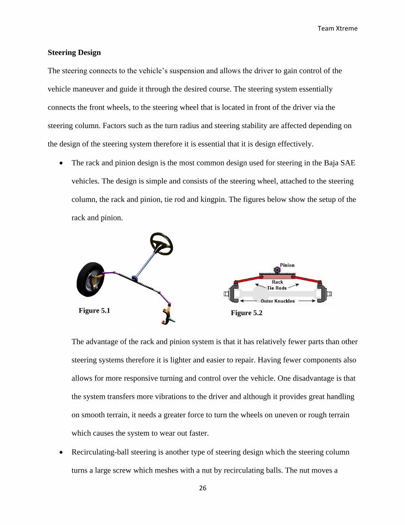
The rack and pinion design is the most common design used for steering in the Baja SAE
vehicles. The design is simple and consists of the steering wheel, attached to the steering
column, the rack and pinion, tie rod and kingpin. The figures below show the setup of the
rack and pinion.
The advantage of the rack and pinion system is that it has relatively fewer parts than other
steering systems therefore it is lighter and easier to repair. Having fewer components also
allows for more responsive turning and control over the vehicle. One disadvantage is that
the system transfers more vibrations to the driver and although it provides great handling
on smooth terrain, it needs a greater force to turn the wheels on uneven or rough terrain
which causes the system to wear out faster.
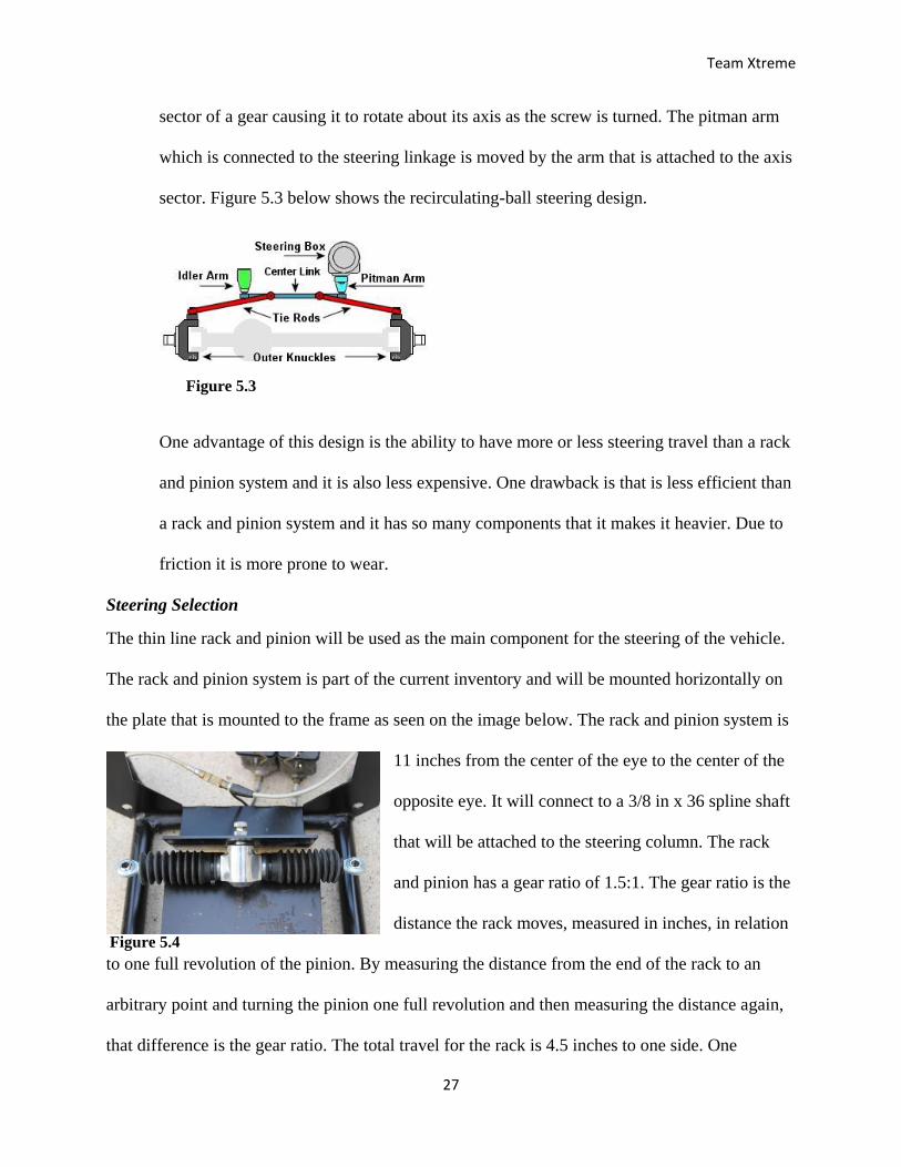
Recirculating-ball steering is another type of steering design which the steering column
turns a large screw which meshes with a nut by recirculating balls. The nut moves a
Figure 5.1 Figure 5.2
Team Xtreme
27
sector of a gear causing it to rotate about its axis as the screw is turned. The pitman arm
which is connected to the steering linkage is moved by the arm that is attached to the axis
sector. Figure 5.3 below shows the recirculating-ball steering design.
One advantage of this design is the ability to have more or less steering travel than a rack
and pinion system and it is also less expensive. One drawback is that is less efficient than
a rack and pinion system and it has so many components that it makes it heavier. Due to
friction it is more prone to wear.
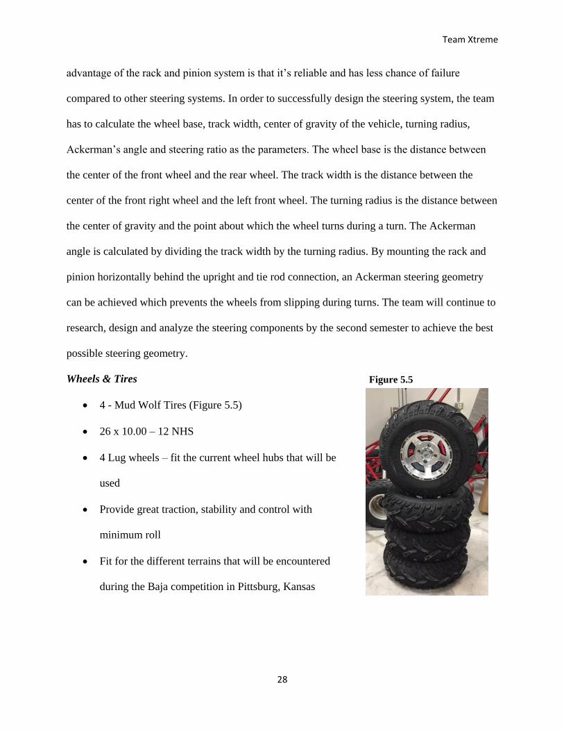
Steering Selection
The thin line rack and pinion will be used as the main component for the steering of the vehicle.
The rack and pinion system is part of the current inventory and will be mounted horizontally on
the plate that is mounted to the frame as seen on the image below. The rack and pinion system is
11 inches from the center of the eye to the center of the
opposite eye. It will connect to a 3/8 in x 36 spline shaft
that will be attached to the steering column. The rack
and pinion has a gear ratio of 1.5:1. The gear ratio is the
distance the rack moves, measured in inches, in relation
to one full revolution of the pinion. By measuring the distance from the end of the rack to an
arbitrary point and turning the pinion one full revolution and then measuring the distance again,
that difference is the gear ratio. The total travel for the rack is 4.5 inches to one side. One
Figure 5.3
Figure 5.4
Team Xtreme
28
advantage of the rack and pinion system is that it’s reliable and has less chance of failure
compared to other steering systems. In order to successfully design the steering system, the team
has to calculate the wheel base, track width, center of gravity of the vehicle, turning radius,
Ackerman’s angle and steering ratio as the parameters. The wheel base is the distance between
the center of the front wheel and the rear wheel. The track width is the distance between the
center of the front right wheel and the left front wheel. The turning radius is the distance between
the center of gravity and the point about which the wheel turns during a turn. The Ackerman
angle is calculated by dividing the track width by the turning radius. By mounting the rack and
pinion horizontally behind the upright and tie rod connection, an Ackerman steering geometry
can be achieved which prevents the wheels from slipping during turns. The team will continue to
research, design and analyze the steering components by the second semester to achieve the best
possible steering geometry.
Wheels & Tires
4 - Mud Wolf Tires (Figure 5.5)
26 x 10.00 – 12 NHS
4 Lug wheels – fit the current wheel hubs that will be
used
Provide great traction, stability and control with
minimum roll
Fit for the different terrains that will be encountered
during the Baja competition in Pittsburg, Kansas
Figure 5.5
Team Xtreme
29
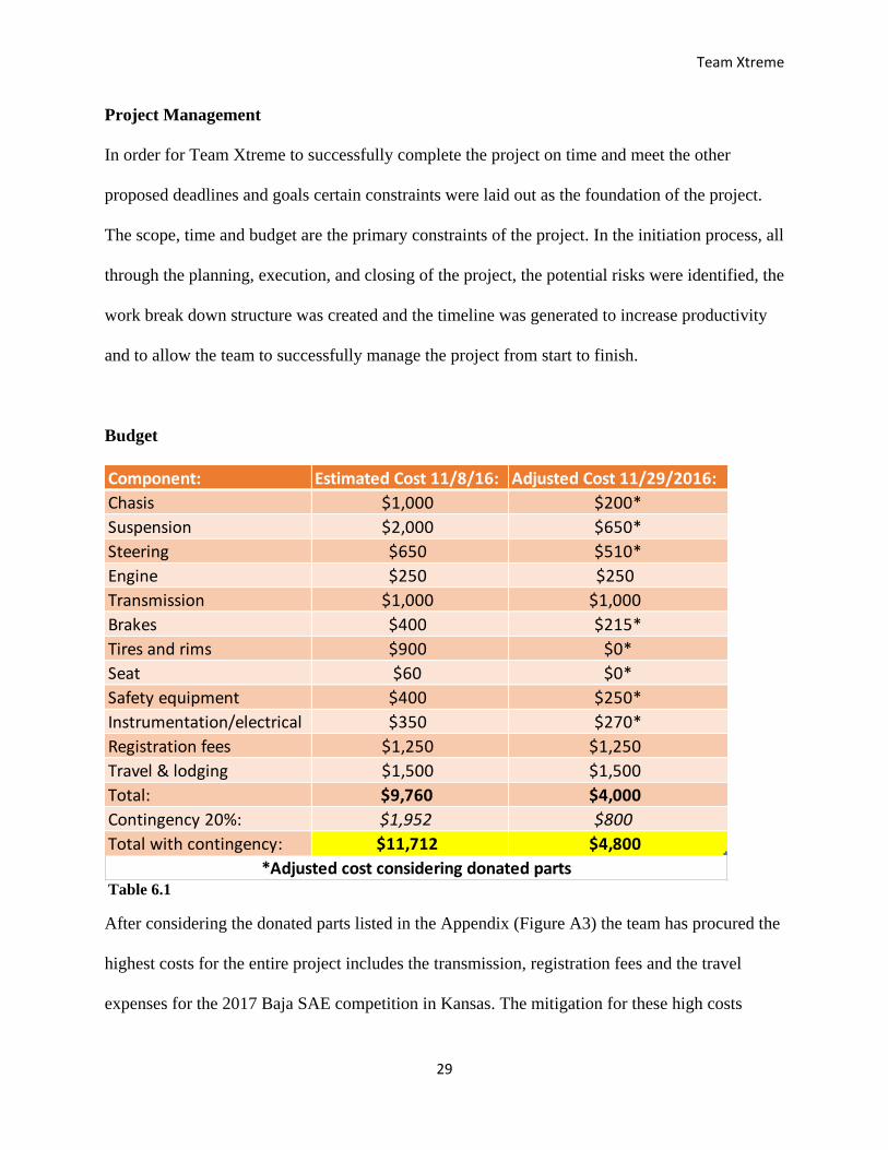
Project Management
In order for Team Xtreme to successfully complete the project on time and meet the other
proposed deadlines and goals certain constraints were laid out as the foundation of the project.
The scope, time and budget are the primary constraints of the project. In the initiation process, all
through the planning, execution, and closing of the project, the potential risks were identified, the
work break down structure was created and the timeline was generated to increase productivity
and to allow the team to successfully manage the project from start to finish.
Budget
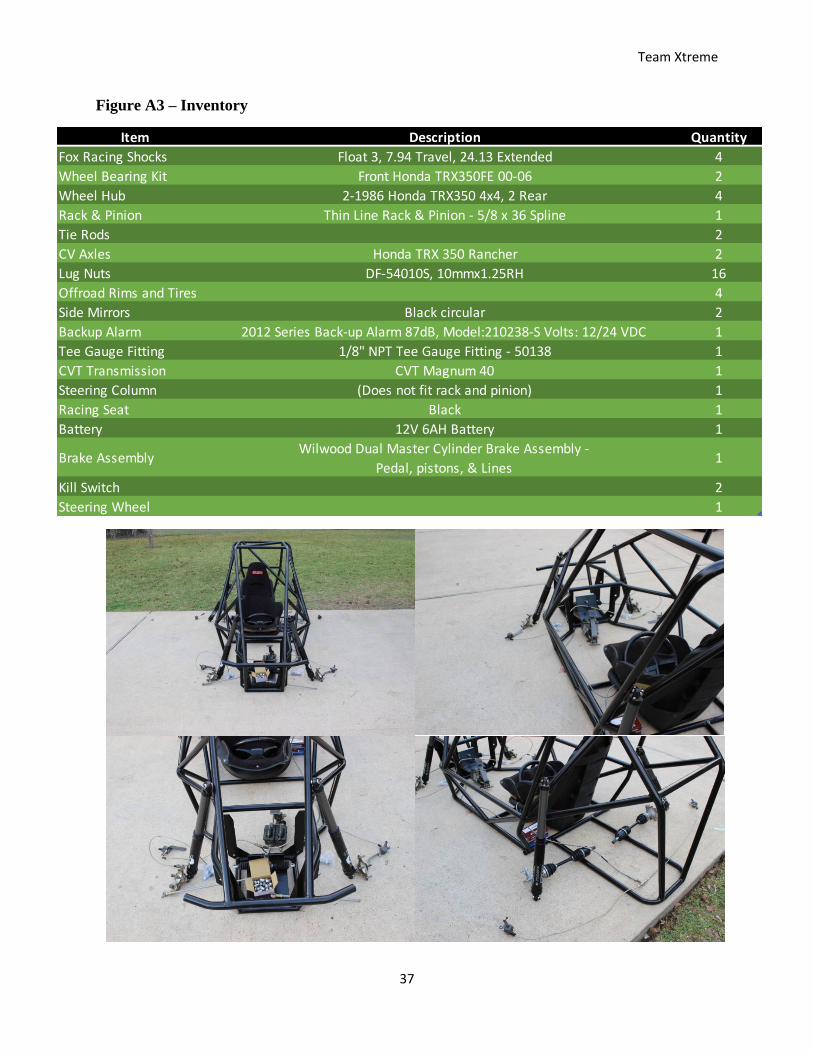
After considering the donated parts listed in the Appendix (Figure A3) the team has procured the
highest costs for the entire project includes the transmission, registration fees and the travel
expenses for the 2017 Baja SAE competition in Kansas. The mitigation for these high costs
Component: Estimated Cost 11/8/16: Adjusted Cost 11/29/2016:
Chasis $1,000 $200*
Suspension $2,000 $650*
Steering $650 $510*
Engine $250 $250
Transmission $1,000 $1,000
Brakes $400 $215*
Tires and rims $900 $0*
Seat $60 $0*
Safety equipment $400 $250*
Instrumentation/electrical $350 $270*
Registration fees $1,250 $1,250
Travel & lodging $1,500 $1,500
Total: $9,760 $4,000
Contingency 20%: $1,952 $800
Total with contingency: $11,712 $4,800
*Adjusted cost considering donated partsTable 6.1

Team Xtreme
30
include making fundraising a weekly focus throughout the semester to raise enough funds for the
registration fees and use a members’ vehicle and borrow a trailer to reduce the cost of travel and
also check routinely for deals on lodging.
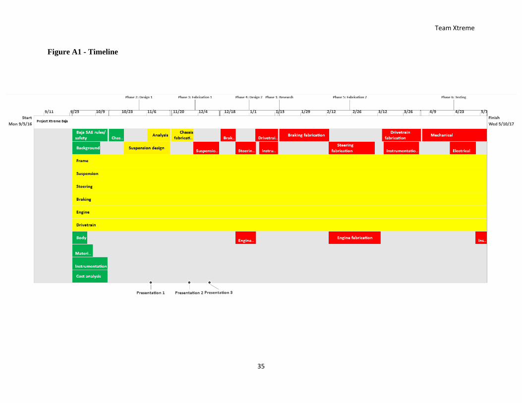
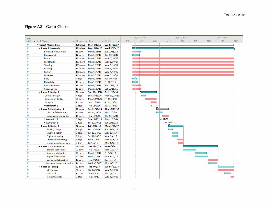
Timeline
Listed in the Appendix (Figure A1) at the end of the report is the timeline for the entire project
which is designed to help the team stay on track. One of the keys to having a successful project
build is time management coupled with strong team work. The timeline has been developed to
keep everyone on track and aware of our current position as well as how much work still needs
to be done. So far we have left the research of the major components open considering we will
tackle most of those tasks in the second semester. Currently we are on the design phase 1 section
of the timeline. In addition to designing the suspension we have also started finishing fabrication
on the existing frame.
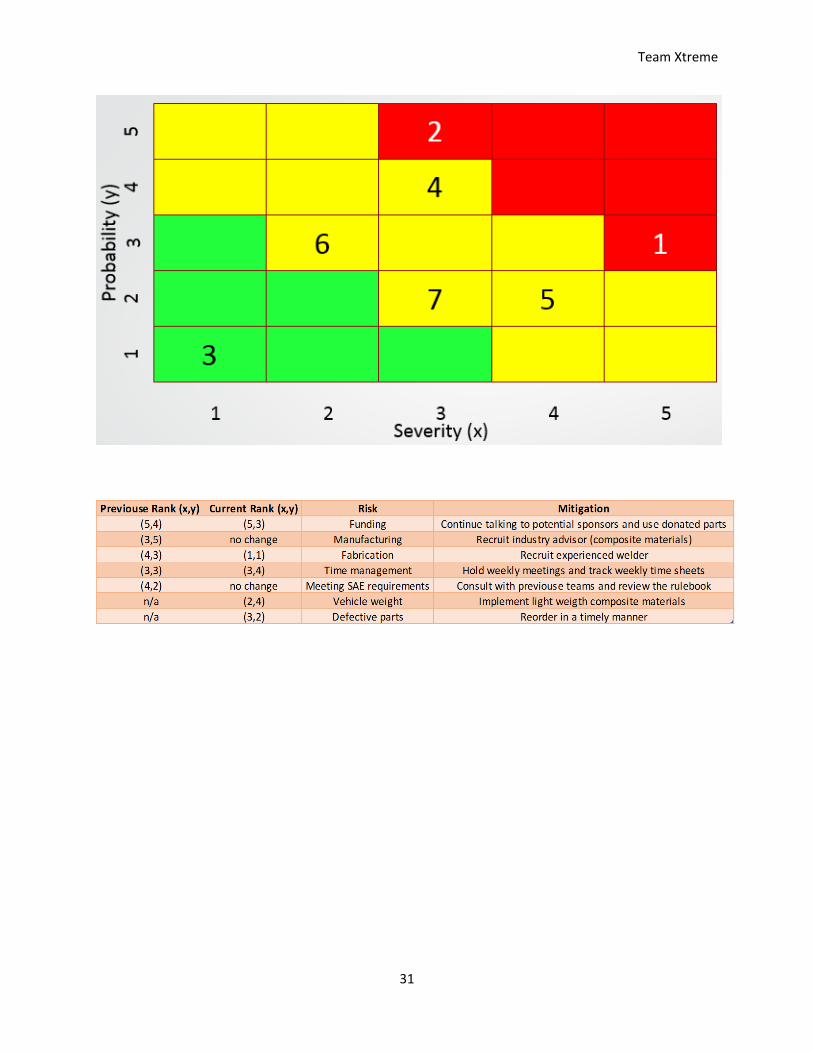
Work Breakdown Structure (WBS)
Risk Matrix
Figure 6.1
Team Xtreme
31

Team Xtreme
32
References
"BAJA Automotive Enthusiasts." Baja Tutor Knowledge Base for BAJA Automotive Enthusiasts.
Web. 15 Oct. 2016. <http://bajatutor.org/>.
"Baja SAE Kansas." - Baja SAE. Web. 1 Sept. 2016. <http://students.sae.org/cds/bajasae/east/>.
CADmantra Technologies Follow. "Chassis Design for Baja Sae." Chassis Design for Baja SAE.
26 Sept. 2015. Web. 26 Sept. 2016. <http://www.slideshare.net/bholapatel/chassis-
design-for-baja-sae>.
"Intrax Racing." Intrax Racing. Web. 20 Oct. 2016. <http://en.intraxracing.nl/techniek/camber,-
caster,-toe-intoe-out/>.
Isaac-Lowry, By Jacob. "Suspension Design: Types of Suspensions - Automotive Articles .com
Magazine." Suspension Design: Types of Suspensions - Automotive Articles .com
Magazine. Web. 6 Sept. 2016.
<http://www.automotivearticles.com/Suspension_Design_Types_of_Suspensions.shtml>.
Michael, John. "The Advantages of Rack & Pinion Steering." EHow. Demand Media. Web. 01
Nov. 2016. <http://www.ehow.com/list_6102863_advantages-rack-pinion-
steering.html>.
"Rack and Pinion Steering System | Advantages | Application." Mechanical Engineering World.
Web. 1 Nov. 2016. <http://www.mechengg.net/2015/03/rack-and-pinion-steering-
system.html>.
"Recirculating Ball." Wikipedia. Wikimedia Foundation. Web. 07 Nov. 2016.
<https://en.wikipedia.org/wiki/Recirculating_ball>.
Team Xtreme
33
"SAE Baja Car." MiniBuggyNet The Ultimate OffRoad Buggy Community RSS. Web. 20 Oct.
2016. <http://www.minibuggy.net/forum/show-off-your-toys-here/6776-sae-baja-car-
7.html>.
Singh, Avinash. Off-Road Suspension Design. 2016. Amazon Inc.
"Trailing Arm or Semi Trailing Arm." Official Baja SAE Forums. Web. 22 Sept. 2016.
<http://forums.bajasae.net/forum/trailing-arm-or-semi-trailing-arm_topic1834.html>.
Team Xtreme
34
APPENDIX
Team Xtreme
35
Figure A1 - Timeline
Team Xtreme
36
Figure A2 – Gantt Chart
Team Xtreme
37
Figure A3 – Inventory
Item Description Quantity
Fox Racing Shocks Float 3, 7.94 Travel, 24.13 Extended 4
Wheel Bearing Kit Front Honda TRX350FE 00-06 2
Wheel Hub 2-1986 Honda TRX350 4x4, 2 Rear 4
Rack & Pinion Thin Line Rack & Pinion - 5/8 x 36 Spline 1
Tie Rods 2
CV Axles Honda TRX 350 Rancher 2
Lug Nuts DF-54010S, 10mmx1.25RH 16
Offroad Rims and Tires 4
Side Mirrors Black circular 2
Backup Alarm 2012 Series Back-up Alarm 87dB, Model:210238-S Volts: 12/24 VDC 1
Tee Gauge Fitting 1/8" NPT Tee Gauge Fitting - 50138 1
CVT Transmission CVT Magnum 40 1
Steering Column (Does not fit rack and pinion) 1
Racing Seat Black 1
Battery 12V 6AH Battery 1
Brake AssemblyWilwood Dual Master Cylinder Brake Assembly -
Pedal, pistons, & Lines1
Kill Switch 2
Steering Wheel 1
Team Xtreme
38
Figure A4 - Examples of Failing Welds: Sample #1 (Destructive Testing)
http://students.sae.org/cds/bajasae/rules
Team Xtreme
39
Figure A5 - Examples of Failing Welds: Sample #2 (Destructive Inspection)
http://students.sae.org/cds/bajasae/rules
Team Xtreme
40
Figure A6 - Examples of Passing Welds
http://students.sae.org/cds/bajasae/rules
Team Xtreme
41
Sponsorship Brochure