2017-2018 first tech challenge pushbot v4a build guide · 2018-01-09 · 2 | first® tech ......
TRANSCRIPT

2017-2018 FIRST® Tech Challenge
PushBot v4a Build Guide Vertical Reach Robot

2 | FIRST® Tech Challenge PushBot v4a Build Guide
Revision 1: 9.13.2017
Sponsor Thank You
Thank you to our generous sponsors for your continued support of the FIRST Tech Challenge!

FIRST® Tech Challenge PushBot v4a Build Guide| 3
Gracious Professionalism® - “Doing your best work while treating others with respect and kindness - It’s what makes FIRST, first.”
Volunteer Thank You
Thank you for taking the time to volunteer for a FIRST® Tech Challenge event. FIRST® and FIRST® Tech Challenge rely heavily on volunteers to ensure events run smoothly and are a fun experience for teams and their families, which could not happen without people like you. With over 4,600 teams competing yearly, your dedication and commitment are essential to the success of each event and the FIRST Tech Challenge program. Thank you for your time and effort in supporting the mission of FIRST!
Revision History
Revision Date Description
1 9/13/2017 Initial Release
1.1 1/9/2018 • New cover page image • New Sponsor thank you image
Contents
Introduction ........................................................................................................................................................ 6
What is FIRST® Tech Challenge? .................................................................................................................. 6
FIRST Tech Challenge Core Values .............................................................................................................. 7
Gracious Professionalism® ................................................................................................................................ 7
The PushBot Guide ........................................................................................................................................... 7
Assemblies ...................................................................................................................................................... 10
Cross Bar Assemblies .................................................................................................................................. 11
Step 1: Cross Bars ................................................................................................................................... 11
Battery Holder Assembly .............................................................................................................................. 12
Step 1: Back Support ................................................................................................................................ 12
Step 2: Front Support ............................................................................................................................... 13
Step 3: Side Support ................................................................................................................................ 15
Phone Holder Assembly ............................................................................................................................... 16

4 | FIRST® Tech Challenge PushBot v4a Build Guide
Revision 1: 9.13.2017
Step 1: Back Support ................................................................................................................................ 16
Step 2: Bottom Support ............................................................................................................................ 17
Step 3: Attachment Brackets .................................................................................................................... 18
Step 4: Side Support ................................................................................................................................ 19
Step 5: Front Support ............................................................................................................................... 20
Tower Assembly .......................................................................................................................................... 21
Step 1: Large Gear ................................................................................................................................... 21
Step 2: Large Gear Support ...................................................................................................................... 22
Step 3: Channel and Small Gear .............................................................................................................. 23
Step 4: Motor Mount ................................................................................................................................. 24
Step 5: Support Brace .............................................................................................................................. 25
Step 6: Flag Holder ................................................................................................................................... 26
Arm Assembly .............................................................................................................................................. 27
Step 1: Motor Mounts ............................................................................................................................... 27
Step 2: Servo Motors ................................................................................................................................ 28
Step 3: Hand Part A .................................................................................................................................. 29
Step 4: Hand Part B .................................................................................................................................. 30
Step 5: Hand Attachment .......................................................................................................................... 31
Step 6: Medium Gear ............................................................................................................................... 32
Step 7: Arm/Tower Axle ............................................................................................................................ 33
Drive Wheel Assemblies .............................................................................................................................. 34
Step 1: Wheel, Gear, and Axle ................................................................................................................. 34
Omni Wheel Assemblies .............................................................................................................................. 35
Step 1: Omni Wheel Unit .......................................................................................................................... 35
Step 2: Omni Wheel and Bushings ........................................................................................................... 36
Step 3: Omni Wheel and Axle ................................................................................................................... 37
Right Rail Assembly ..................................................................................................................................... 38
Step 1: Rail ............................................................................................................................................... 38
Step 2: Rail and Drive Wheel .................................................................................................................... 39
Step 3: Rail and Omni Wheels .................................................................................................................. 40
Step 4: Motor Mount ................................................................................................................................. 41
Left Rail Assembly ....................................................................................................................................... 42
Step 1: Rail ............................................................................................................................................... 42
Step 2: Rail and Drive Wheel .................................................................................................................... 43
Step 3: Rail and Omni Wheels .................................................................................................................. 44
Step 4: Motor Mount ................................................................................................................................. 45

FIRST® Tech Challenge PushBot v4a Build Guide| 5
Gracious Professionalism® - “Doing your best work while treating others with respect and kindness - It’s what makes FIRST, first.”
Motor Hub and Gear Assemblies ................................................................................................................. 46
Step 1: Motor Encoders ............................................................................................................................ 46
Step 2: Gear and DC Motor ...................................................................................................................... 47
Chassis ........................................................................................................................................................... 48
Step 1: Left Rail and Back Cross Bar ........................................................................................................... 48
Step 2: Adding the Right Rail ....................................................................................................................... 49
Step 3: Adding the Front Cross Bar .............................................................................................................. 50
Step 4: Adding the Front Brace .................................................................................................................... 51
Step 5: Adding the Tower ............................................................................................................................. 52
Step 6: Adding the Arm ................................................................................................................................ 53
Step 7: Adding the Expansion Hub Support Brackets................................................................................... 55
Step 8: Adding the Right Side Panel Support Bracket .................................................................................. 56
Step 9: Adding the Phone Holder ................................................................................................................. 57
Step 10: Adding the Battery Holder .............................................................................................................. 58
Step 11: Adding the Rev Robotics Expansion Hub ....................................................................................... 59
Step 12: Adding the Right Side Panel .......................................................................................................... 60
Step 13: Adding the Left Side Panel and Wiring Bracket .............................................................................. 62
Step 14: Adding the Power Switch Plate ...................................................................................................... 63
Step 15: Install Arm Motor ............................................................................................................................ 64
Step 16: Install Drive Motors ........................................................................................................................ 65
Electronics ....................................................................................................................................................... 66
Robot Controller ........................................................................................................................................... 66
Step 1: Add the Robot Controller Cell Phone to the Chassis .................................................................... 66
Step 2: Connect the Phone to the USB Cable .......................................................................................... 67
Step 3: Connect the USB Cable to the Micro USB OTG Adapter Cable .................................................... 67
Step 4: Connect the Micro USB OTG Adapter Cable to the Expansion Hub ............................................. 68
Servos ......................................................................................................................................................... 69
Step 1: Servo Extension Wires to Servos ................................................................................................. 69
Step 2: Servo Extension Wires to Expansion Hub .................................................................................... 69
Encoders ...................................................................................................................................................... 70
Step 1: Level Shifter Wires to Level Shifters ............................................................................................. 70
Step 2: Level Shifters to Encoder Wires ................................................................................................... 71
Step 3: Level Shifter Wires to Expansion Hub .......................................................................................... 71
DC Motors .................................................................................................................................................... 72
Step 1: Motor Power Cable to Extension Hub Cable ................................................................................. 72
Step 2: Motor Power Cable to Extension Hub Cable ................................................................................. 72
Battery and Switch ....................................................................................................................................... 73

6 | FIRST® Tech Challenge PushBot v4a Build Guide
Revision 1: 9.13.2017
Step 1: Install Battery ............................................................................................................................... 73
Step 2: Install Switch ................................................................................................................................ 74
Step 3: Connect the Switch to the Switch Adapter Cable .......................................................................... 75
Step 4: Connect the Battery to the Switch Adapter Cable ......................................................................... 75
Final Steps ...................................................................................................................................................... 76
Wiring Safety ............................................................................................................................................... 76
Mesh Gears Properly ................................................................................................................................... 76
Square the Frame ........................................................................................................................................ 77
Optimizing the Phone Holder ....................................................................................................................... 77
Optimizing the Battery Holder ...................................................................................................................... 77
Optimizing the Hand/Grippers ...................................................................................................................... 77
Add Team Numbers ..................................................................................................................................... 77
Appendix A – Resources ................................................................................................................................. 78
Game Forum Q&A ....................................................................................................................................... 78
FIRST Tech Challenge Game Manuals ........................................................................................................ 78
FIRST Headquarters Pre-Event Support ...................................................................................................... 78
FIRST Websites ........................................................................................................................................... 78
FIRST Tech Challenge Social Media ........................................................................................................... 78
Feedback ..................................................................................................................................................... 78
Appendix B: Bill of Materials List ...................................................................................................................... 79
Special Thanks and Best Wishes .................................................................................................................... 80
Introduction
What is FIRST® Tech Challenge?
FIRST Tech Challenge is a student-centered program that focuses on giving students a unique and stimulating experience. Each year, teams engage in a new Game where they design, build, test, and program autonomous and driver operated robots that must perform a series of tasks.
They also cultivate life skills such as:
• Planning, brainstorming, and creative problem-solving.
• Research and technical skills.
• Collaboration and teamwork.
• Appreciating differences and respecting the ideas and contributions of others.
To learn more about FIRST Tech Challenge and other FIRST® Programs, visit www.firstinspires.org.
FIRST Tech Challenge is MORE THAN ROBOTSSM!
While competing, students develop personal and
professional skills they will be able to rely on
throughout their life.

FIRST® Tech Challenge PushBot v4a Build Guide| 7
Gracious Professionalism® - “Doing your best work while treating others with respect and kindness - It’s what makes FIRST, first.”
FIRST Tech Challenge Core Values FIRST asks everyone who takes part in FIRST Tech Challenge to uphold the following values:
• We display Gracious Professionalism® with everyone we engage with and in everything we do.
• We act with integrity.
• We have fun.
• We are a welcoming community of students, mentors, and volunteers.
• What we learn is more important than what we win.
• We respect each other and celebrate our diversity.
• Students and adults work together to find solutions to challenges.
• We honor the spirit of friendly competition.
• We behave with courtesy and compassion for others always.
• We act as ambassadors for FIRST and FIRST Tech Challenge.
• We inspire others to adopt these values.
Gracious Professionalism®
FIRST uses this term to describe our programs’ intent and is shared with all young people engaging in FIRST programs. At FIRST, team members help other team members, but they also help other teams.
Gracious Professionalism® is not clearly defined for a reason. It has different meanings to everyone.
Some possible meanings of Gracious Professionalism include:
• Gracious attitudes and behaviors are win-win.
• Gracious folks respect others and let that respect show in their actions.
• Gracious Professionals make valued contributions in a way that is pleasing to others and to themselves.
In FIRST, Gracious Professionalism teaches teams and student participants:
• Learn to be strong competitors, but also treat one another with respect and kindness in the process.
• Avoid leaving anyone feeling as if they are excluded or unappreciated.
• Knowledge, pride and empathy should be comfortably and genuinely blended.
In the end, Gracious Professionalism® is part of everyday life. When professionals use their knowledge in a graciously and individuals act with integrity and sensitivity, everyone wins, and society benefits.
Watch Dr. Woodie Flowers explain Gracious Professionalism in this short video.
The PushBot Guide
There are three versions of the Push Bot. PBv1 (created in 2014) used the NXT and Samantha units for control and communication. PBv2 (created in 2015) was introduced cell phones to replace the NXT Mindstorm and Samantha units. Modern Robotics modules were introduced to replace the HiTechnic controllers. PBv3 (created in 2016) used the same electronics as PBv2, but had a lower center of gravity. PBv4 is being created in 2017 to introduce the Rev Robotics Expansion hub, which can be used to replace the Modern Robotics
An example of Gracious Professionalism is patiently
listening to a team’s question and providing support despite
having several pressing things to do on the day of the
event.
8 | FIRST® Tech Challenge PushBot v4a Build Guide
Revision 1: 9.13.2017
controllers. The Modern Robotics electronics are still an option, so if you are using those electronics, then refer to the building instructions for PBv2 and PBv3. Use the latest FTC SDK for programming regardless of the electronics in use.
The PBv2 and PBv3 robots are being revised to use the REV expansion hub instead of the Modern Robotics modules for the 2017 season. The revised versions will be known as PBv4a (counterpart of PBv2 - reaches higher with its arm and has a higher center of gravity) and PBv4b (counterpart of PBv3 - reaches further horizontally with its arm and has a lower center of gravity).
Refer to the game rules to determine which version is desired. If the season’s game has a goal that requires reaching high objects/goals, then PBv4a would be desired. If the season’s game has a ramp onto which the robot must drive, then build PBv4b. This document contains the hardware and wiring instructions to build PBv4a.
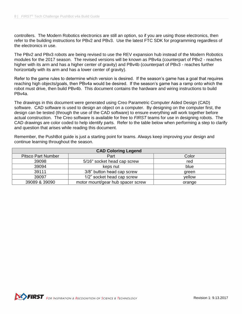
The drawings in this document were generated using Creo Parametric Computer Aided Design (CAD) software. CAD software is used to design an object on a computer. By designing on the computer first, the design can be tested (through the use of the CAD software) to ensure everything will work together before actual construction. The Creo software is available for free to FIRST teams for use in designing robots. The CAD drawings are color coded to help identify parts. Refer to the table below when performing a step to clarify and question that arises while reading this document.
Remember, the PushBot guide is just a starting point for teams. Always keep improving your design and continue learning throughout the season.
CAD Coloring Legend
Pitsco Part Number Part Color
39098 5/16" socket head cap screw red
39094 keps nut blue
39111 3/8” button head cap screw green
39097 1/2” socket head cap screw yellow
39089 & 39090 motor mount/gear hub spacer screw orange

FIRST® Tech Challenge PushBot v4a Build Guide| 9
Gracious Professionalism® - “Doing your best work while treating others with respect and kindness - It’s what makes FIRST, first.”
The above image shows the left side of the robot.
The above image shows the right side of the robot.

10 | FIRST® Tech Challenge PushBot v4a Build Guide
Revision 1: 9.13.2017
Assemblies
This section will outline the construction of the assemblies that will later be used to complete the chassis. Only the parts and tools included in the TETRIX Kit of Parts will be needed to build the robot. Make sure that set screws are installed in all of the axle hubs, motor hubs, and axle collars. If these parts are unfamiliar, then refer to the legend provided in the Kit of Parts.
PBv4a uses drive wheels on the back of the robot, because that is where the most weight is. This weight is needed to help the wheels grip the surface better. Omni wheels are on the front of the robot, which allows the robot to turn more easily. The omni wheels can slide sideways with very little friction due to the rollers.
PBv4a uses two DC motors to power the drive wheels. It uses one DC motor to raise and lower the arm. The Kit of Parts includes an additional motor, which can be retained as a spare motor (in the event one of the three fail) or it can be used to power another mechanism, such as a sweeper for balls or a lifter for blocks.
For most of the steps in this section, the top image shows the necessary parts; the lower image shows the completed assembly.
FIRST® Tech Challenge PushBot v4a Build Guide| 11
Gracious Professionalism® - “Doing your best work while treating others with respect and kindness - It’s what makes FIRST, first.”
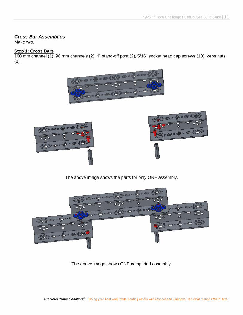
Cross Bar Assemblies Make two.
Step 1: Cross Bars 160 mm channel (1), 96 mm channels (2), 1” stand-off post (2), 5/16" socket head cap screws (10), keps nuts (8)
The above image shows the parts for only ONE assembly.
The above image shows ONE completed assembly.

12 | FIRST® Tech Challenge PushBot v4a Build Guide
Revision 1: 9.13.2017
Battery Holder Assembly Step 1: Back Support 64 mm x 192 mm flat building plate (2), 1” stand-off post (2), 3/8” button head cap screws (2), 5/16" socket head cap screws (2), keps nuts (2)

FIRST® Tech Challenge PushBot v4a Build Guide| 13
Gracious Professionalism® - “Doing your best work while treating others with respect and kindness - It’s what makes FIRST, first.”
Step 2: Front Support Assembly from previous step (rotated in this view), 160 mm flat (1), 1” stand-off post (2), 5/16" socket head cap screws (2)

14 | FIRST® Tech Challenge PushBot v4a Build Guide
Revision 1: 9.13.2017

FIRST® Tech Challenge PushBot v4a Build Guide| 15
Gracious Professionalism® - “Doing your best work while treating others with respect and kindness - It’s what makes FIRST, first.”
Step 3: Side Support battery clip (2), 5/16" socket head cap screws (4)

16 | FIRST® Tech Challenge PushBot v4a Build Guide
Revision 1: 9.13.2017
Phone Holder Assembly Step 1: Back Support 160 mm flats (2), flat bracket (1), 3/8” button head cap screws (4), keps nuts (4)

FIRST® Tech Challenge PushBot v4a Build Guide| 17
Gracious Professionalism® - “Doing your best work while treating others with respect and kindness - It’s what makes FIRST, first.”
Step 2: Bottom Support assembly from the previous step, flat bracket (1), inside C connector (2), button head cap screws (4), kep nuts (4).
Note: the inside C connector is behind the vertical flat brackets.

18 | FIRST® Tech Challenge PushBot v4a Build Guide
Revision 1: 9.13.2017
Step 3: Attachment Brackets assembly from the previous step, inside corner bracket (2), 3/8”button head cap screws (4), keps nuts (4).

FIRST® Tech Challenge PushBot v4a Build Guide| 19
Gracious Professionalism® - “Doing your best work while treating others with respect and kindness - It’s what makes FIRST, first.”
Step 4: Side Support assembly from the previous step, 1" stand-off posts (2), 1/2" socket head cap screws (2).
Note: the stand-off posts are not placed symmetrically.

20 | FIRST® Tech Challenge PushBot v4a Build Guide
Revision 1: 9.13.2017
Step 5: Front Support assembly from the previous step, 96 mm flats (2), 5/16" socket head cap screws (2), button head cap screws (2) (shown in green inside the inside C connectors), keps nuts (2)

FIRST® Tech Challenge PushBot v4a Build Guide| 21
Gracious Professionalism® - “Doing your best work while treating others with respect and kindness - It’s what makes FIRST, first.”
Tower Assembly Step 1: Large Gear 120-tooth gear (1), 100 mm axle hub (1), 1/2" socket head cap screws (4), 100 mm axle (1)

22 | FIRST® Tech Challenge PushBot v4a Build Guide
Revision 1: 9.13.2017
Step 2: Large Gear Support assembly from previous step, 3/8” nylon axle spacer (1), bronze bushing (1)

FIRST® Tech Challenge PushBot v4a Build Guide| 23
Gracious Professionalism® - “Doing your best work while treating others with respect and kindness - It’s what makes FIRST, first.”
Step 3: Channel and Small Gear assembly from previous step, 288 mm channel (1), bronze bushing (1), 1/8" axle spacer (1), button head cap screws (4), 40-tooth gear (1), axle hub (1)
Order from right to left: 120-tooth gear, axle hub, 3/8" axle spacer, bronze bushing, channel, bronze bushing, 1/8" spacer, 40-tooth gear, axle hub

24 | FIRST® Tech Challenge PushBot v4a Build Guide
Revision 1: 9.13.2017
Step 4: Motor Mount assembly from the previous step, motor mount (1) with included screws (2), keps nuts (2).
FIRST® Tech Challenge PushBot v4a Build Guide| 25
Gracious Professionalism® - “Doing your best work while treating others with respect and kindness - It’s what makes FIRST, first.”
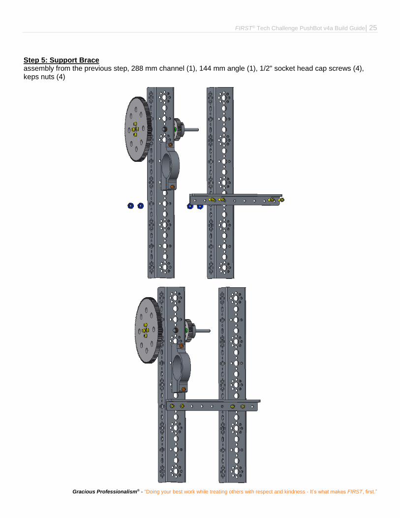
Step 5: Support Brace assembly from the previous step, 288 mm channel (1), 144 mm angle (1), 1/2" socket head cap screws (4), keps nuts (4)

26 | FIRST® Tech Challenge PushBot v4a Build Guide
Revision 1: 9.13.2017
Step 6: Flag Holder assembly from the previous step, hard point connectors (2), 1/2" socket head cap screws (4), keps nuts (4)

FIRST® Tech Challenge PushBot v4a Build Guide| 27
Gracious Professionalism® - “Doing your best work while treating others with respect and kindness - It’s what makes FIRST, first.”
Arm Assembly Step 1: Motor Mounts 416 mm channel (1), single standard-scale servo motor mounting bracket (2), 3/8” button head cap screws (8), keps nuts (8)
28 | FIRST® Tech Challenge PushBot v4a Build Guide
Revision 1: 9.13.2017
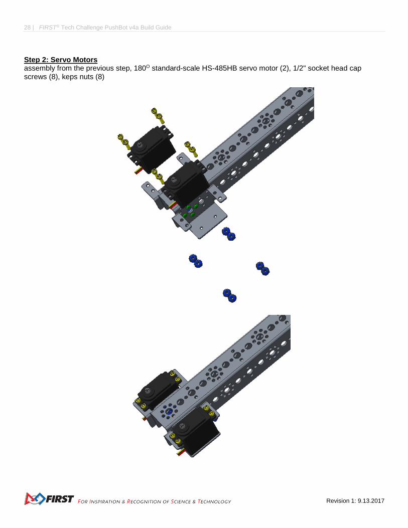
Step 2: Servo Motors assembly from the previous step, 180O standard-scale HS-485HB servo motor (2), 1/2" socket head cap screws (8), keps nuts (8)

FIRST® Tech Challenge PushBot v4a Build Guide| 29
Gracious Professionalism® - “Doing your best work while treating others with respect and kindness - It’s what makes FIRST, first.”
Step 3: Hand Part A servo horn - metal (2), flat bracket (2), 3/8” button head cap screws (8), keps nuts (8)

30 | FIRST® Tech Challenge PushBot v4a Build Guide
Revision 1: 9.13.2017
Step 4: Hand Part B assembly from the previous step, 96 mm flats (2), L bracket (2), 5/16" socket head cap screws (8), 1/2" socket head cap screws (4), keps nuts (12)

FIRST® Tech Challenge PushBot v4a Build Guide| 31
Gracious Professionalism® - “Doing your best work while treating others with respect and kindness - It’s what makes FIRST, first.”
Step 5: Hand Attachment assembly from step 2, assemblies from step 4.
Remove the black screw from the center of the plastic servo horn. Use this screw to attach the hand/grippers. To set the position of the grippers, rotate the servo to the fully open position and install the gripper so that it is opened just past vertical. This should get the servo in approximately the correct position.

32 | FIRST® Tech Challenge PushBot v4a Build Guide
Revision 1: 9.13.2017
Step 6: Medium Gear assembly from the previous step, 80-tooth gear (1), gear hub spacer (1) with included screws (4), axle hub (1)
Note: Use the other end of the previous assembly (i.e. the end opposite the hand).

FIRST® Tech Challenge PushBot v4a Build Guide| 33
Gracious Professionalism® - “Doing your best work while treating others with respect and kindness - It’s what makes FIRST, first.”
Step 7: Arm/Tower Axle assembly from the previous step, 1/8” nylon axle spacer (2), bronze bushing (3), flat spacer (1), axle (1)

34 | FIRST® Tech Challenge PushBot v4a Build Guide
Revision 1: 9.13.2017
Drive Wheel Assemblies Make two.
Step 1: Wheel, Gear, and Axle 4" wheel (1), hub gear spacer (1) with included screws (4), 80 tooth gear (1), axle hub (1), 1/8” nylon spacer, bronze bushing (1), 100 mm axle (1)
Order from left to right: screws, wheel, gear hub spacer, gear, axle hub, spacer, bronze bushing
The images show only one wheel. Make two.

FIRST® Tech Challenge PushBot v4a Build Guide| 35
Gracious Professionalism® - “Doing your best work while treating others with respect and kindness - It’s what makes FIRST, first.”
Omni Wheel Assemblies Make two.
Assemblethe omni wheels according to the instructions that come in the omni wheel pack.
Step 1: Omni Wheel Unit 4" omni wheel half (2), joining ring (1) with included screws (4). The order is omni wheel, joining ring, omni wheel.
The images show only one wheel. Make two.

36 | FIRST® Tech Challenge PushBot v4a Build Guide
Revision 1: 9.13.2017
Step 2: Omni Wheel and Bushings assemblies from previous step, bronze bushings (2)
The images show only one wheel. Make two.
It’s very hard to see, but the bushing is inside the axle opening.

FIRST® Tech Challenge PushBot v4a Build Guide| 37
Gracious Professionalism® - “Doing your best work while treating others with respect and kindness - It’s what makes FIRST, first.”
Step 3: Omni Wheel and Axle axle set collar (1), 1/8” nylon spacer (2), bronze bushing (1), 100 mm axle (1)

38 | FIRST® Tech Challenge PushBot v4a Build Guide
Revision 1: 9.13.2017
Right Rail Assembly Step 1: Rail 32 mm channel (1), 160 mm channel (1), 288 mm channel (1), 5/16" socket head cap screws (4), 1/2" socket head cap screws (2), keps nuts (6)

FIRST® Tech Challenge PushBot v4a Build Guide| 39
Gracious Professionalism® - “Doing your best work while treating others with respect and kindness - It’s what makes FIRST, first.”
Step 2: Rail and Drive Wheel assembly from the previous step, drive wheel assembly (1), 1/8" nylon spacer (1), axle collar (1), bronze bushing (1)
Order from top to bottom: drive wheel assembly (including its 1/8" spacer, bronze bushing), channel, bronze bushing, 1/8" spacer, axle collar
40 | FIRST® Tech Challenge PushBot v4a Build Guide
Revision 1: 9.13.2017
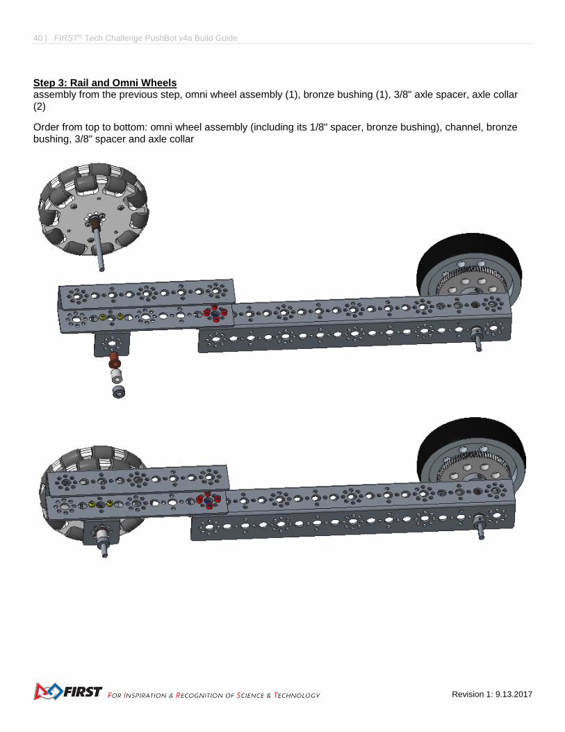
Step 3: Rail and Omni Wheels assembly from the previous step, omni wheel assembly (1), bronze bushing (1), 3/8" axle spacer, axle collar (2)
Order from top to bottom: omni wheel assembly (including its 1/8" spacer, bronze bushing), channel, bronze bushing, 3/8" spacer and axle collar

FIRST® Tech Challenge PushBot v4a Build Guide| 41
Gracious Professionalism® - “Doing your best work while treating others with respect and kindness - It’s what makes FIRST, first.”
Step 4: Motor Mount assembly from the previous step, motor mount (1) with included screws (2), keps nuts (2)
42 | FIRST® Tech Challenge PushBot v4a Build Guide
Revision 1: 9.13.2017
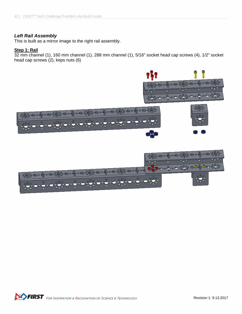
Left Rail Assembly This is built as a mirror image to the right rail assembly.
Step 1: Rail 32 mm channel (1), 160 mm channel (1), 288 mm channel (1), 5/16" socket head cap screws (4), 1/2" socket head cap screws (2), keps nuts (6)

FIRST® Tech Challenge PushBot v4a Build Guide| 43
Gracious Professionalism® - “Doing your best work while treating others with respect and kindness - It’s what makes FIRST, first.”
Step 2: Rail and Drive Wheel assembly from the previous step, drive wheel assembly (1), bronze bushing (2), 1/8" axle spacer (2), axle collar (1)
Order from top to bottom: drive wheel assembly (including its 1/8" spacer, bronze bushing), channel, bronze bushing, 1/8" spacer, axle collar

44 | FIRST® Tech Challenge PushBot v4a Build Guide
Revision 1: 9.13.2017
Step 3: Rail and Omni Wheels assembly from the previous step, omni wheel assembly (1), bronze bushing (1), 3/8" axle spacer, axle collar (2), 100 mm axle (1)
Order from top to bottom: omni wheel assembly (including its 1/8" spacer, bronze bushing), channel, bronze bushing, 3/8" spacer, axle collar

FIRST® Tech Challenge PushBot v4a Build Guide| 45
Gracious Professionalism® - “Doing your best work while treating others with respect and kindness - It’s what makes FIRST, first.”
Step 4: Motor Mount assembly from the previous step, motor mount (1) with included screws (2), keps nuts (2)

46 | FIRST® Tech Challenge PushBot v4a Build Guide
Revision 1: 9.13.2017
Motor Hub and Gear Assemblies Make three.
Step 1: Motor Encoders Make two.
DC motor (1), encoder (1)
Refer to the instructions from the encoder package to install the encoder onto the motor. Encoder styles vary, so the one in the kit of parts may not look like the one in this document.
These images show only one motor. Make two.
FIRST® Tech Challenge PushBot v4a Build Guide| 47
Gracious Professionalism® - “Doing your best work while treating others with respect and kindness - It’s what makes FIRST, first.”
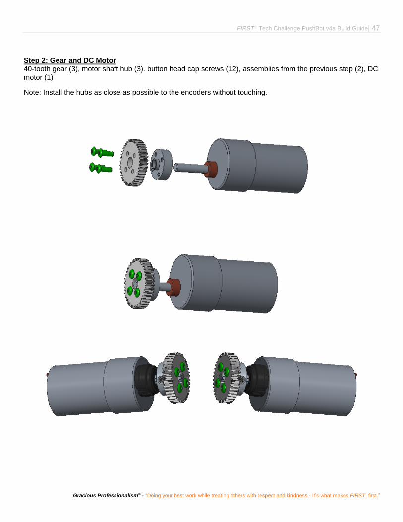
Step 2: Gear and DC Motor 40-tooth gear (3), motor shaft hub (3). button head cap screws (12), assemblies from the previous step (2), DC motor (1)
Note: Install the hubs as close as possible to the encoders without touching.

48 | FIRST® Tech Challenge PushBot v4a Build Guide
Revision 1: 9.13.2017
Chassis
Step 1: Left Rail and Back Cross Bar left chassis rail assembly (1), cross bar assembly (1), 5/16" socket head cap screws (4), keps nuts (4)

FIRST® Tech Challenge PushBot v4a Build Guide| 49
Gracious Professionalism® - “Doing your best work while treating others with respect and kindness - It’s what makes FIRST, first.”
Step 2: Adding the Right Rail assembly from the previous step, right chassis rail assembly (1), 5/16" socket head cap screws (4), keps nuts (4)

50 | FIRST® Tech Challenge PushBot v4a Build Guide
Revision 1: 9.13.2017
Step 3: Adding the Front Cross Bar assembly from the previous step, cross bar assembly (1), 5/16" socket head cap screws (8), keps nuts (8)
FIRST® Tech Challenge PushBot v4a Build Guide| 51
Gracious Professionalism® - “Doing your best work while treating others with respect and kindness - It’s what makes FIRST, first.”
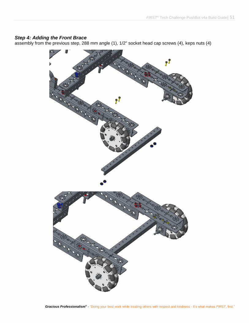
Step 4: Adding the Front Brace assembly from the previous step, 288 mm angle (1), 1/2" socket head cap screws (4), keps nuts (4)

52 | FIRST® Tech Challenge PushBot v4a Build Guide
Revision 1: 9.13.2017
Step 5: Adding the Tower assembly from the previous step, tower assembly, 1/2" socket head cap screws (6), keps nuts (6)

FIRST® Tech Challenge PushBot v4a Build Guide| 53
Gracious Professionalism® - “Doing your best work while treating others with respect and kindness - It’s what makes FIRST, first.”
Step 6: Adding the Arm assembly from the previous step, arm assembly
Order from left to right: channel, bronze bushing, 1/8" nylon spacer, arm, flat spacer, bronze bushing, 1/8” nylon spacer, bronze bushing, channel

54 | FIRST® Tech Challenge PushBot v4a Build Guide
Revision 1: 9.13.2017
FIRST® Tech Challenge PushBot v4a Build Guide| 55
Gracious Professionalism® - “Doing your best work while treating others with respect and kindness - It’s what makes FIRST, first.”
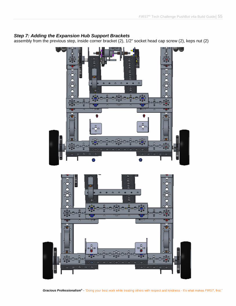
Step 7: Adding the Expansion Hub Support Brackets assembly from the previous step, inside corner bracket (2), 1/2" socket head cap screw (2), keps nut (2)
56 | FIRST® Tech Challenge PushBot v4a Build Guide
Revision 1: 9.13.2017
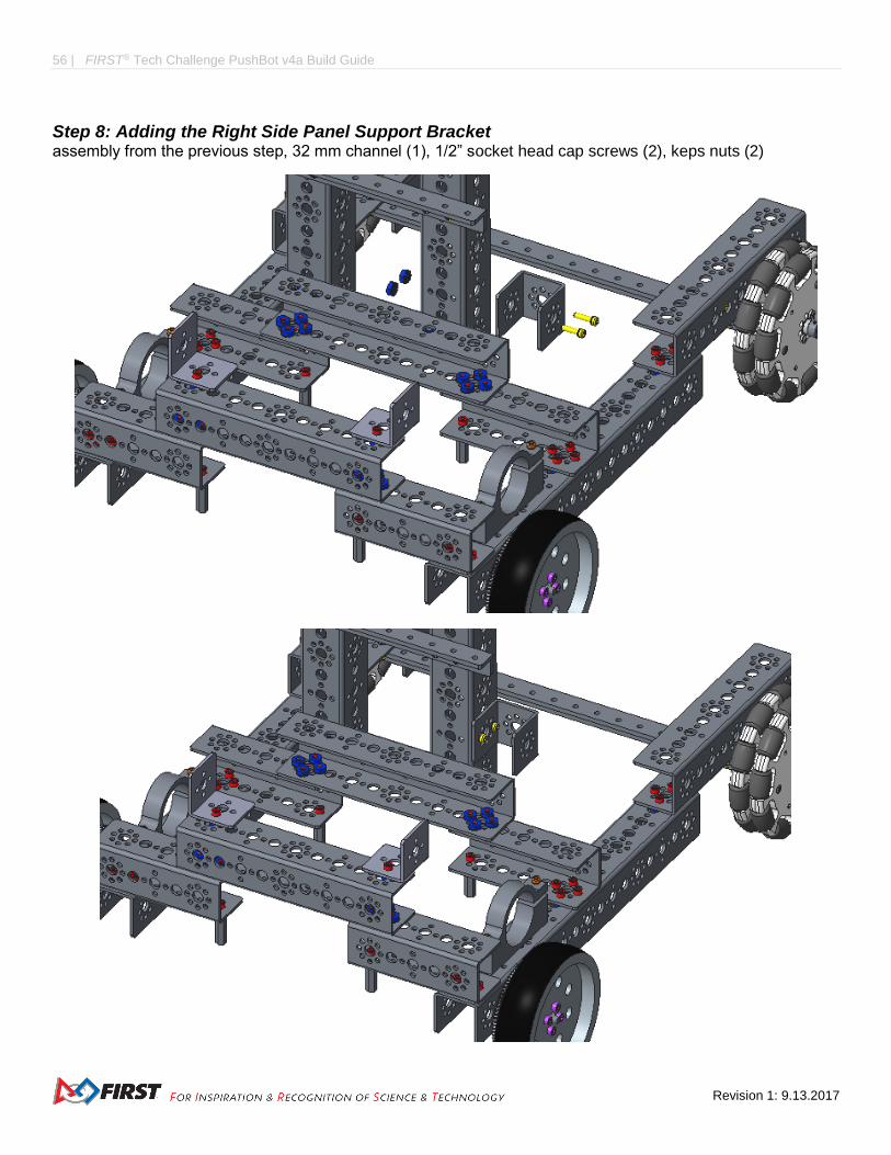
Step 8: Adding the Right Side Panel Support Bracket assembly from the previous step, 32 mm channel (1), 1/2” socket head cap screws (2), keps nuts (2)
FIRST® Tech Challenge PushBot v4a Build Guide| 57
Gracious Professionalism® - “Doing your best work while treating others with respect and kindness - It’s what makes FIRST, first.”
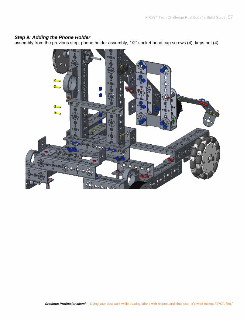
Step 9: Adding the Phone Holder assembly from the previous step, phone holder assembly, 1/2” socket head cap screws (4), keps nut (4)

58 | FIRST® Tech Challenge PushBot v4a Build Guide
Revision 1: 9.13.2017
Step 10: Adding the Battery Holder assembly from the previous step, battery holder assembly, 1/2” socket head cap screws (4)

FIRST® Tech Challenge PushBot v4a Build Guide| 59
Gracious Professionalism® - “Doing your best work while treating others with respect and kindness - It’s what makes FIRST, first.”
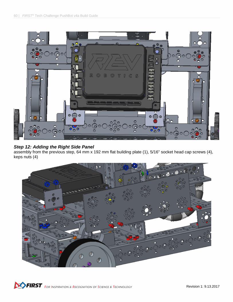
Step 11: Adding the Rev Robotics Expansion Hub
60 | FIRST® Tech Challenge PushBot v4a Build Guide
Revision 1: 9.13.2017
Step 12: Adding the Right Side Panel assembly from the previous step, 64 mm x 192 mm flat building plate (1), 5/16" socket head cap screws (4), keps nuts (4)

FIRST® Tech Challenge PushBot v4a Build Guide| 61
Gracious Professionalism® - “Doing your best work while treating others with respect and kindness - It’s what makes FIRST, first.”

62 | FIRST® Tech Challenge PushBot v4a Build Guide
Revision 1: 9.13.2017
Step 13: Adding the Left Side Panel and Wiring Bracket assembly from previous step, 64 mm x 192 mm flat building plate (1), 5/16" socket head cap screws (4), 1/2” socket head cap screws (2), l-bracket (1), keps nuts (6)

FIRST® Tech Challenge PushBot v4a Build Guide| 63
Gracious Professionalism® - “Doing your best work while treating others with respect and kindness - It’s what makes FIRST, first.”
Step 14: Adding the Power Switch Plate assembly from the previous step, power switch plate (1), 1/2” socket head cap screws (2), keps nuts (2)

64 | FIRST® Tech Challenge PushBot v4a Build Guide
Revision 1: 9.13.2017
Step 15: Install Arm Motor chassis, gear and DC motor assembly (1)
FIRST® Tech Challenge PushBot v4a Build Guide| 65
Gracious Professionalism® - “Doing your best work while treating others with respect and kindness - It’s what makes FIRST, first.”
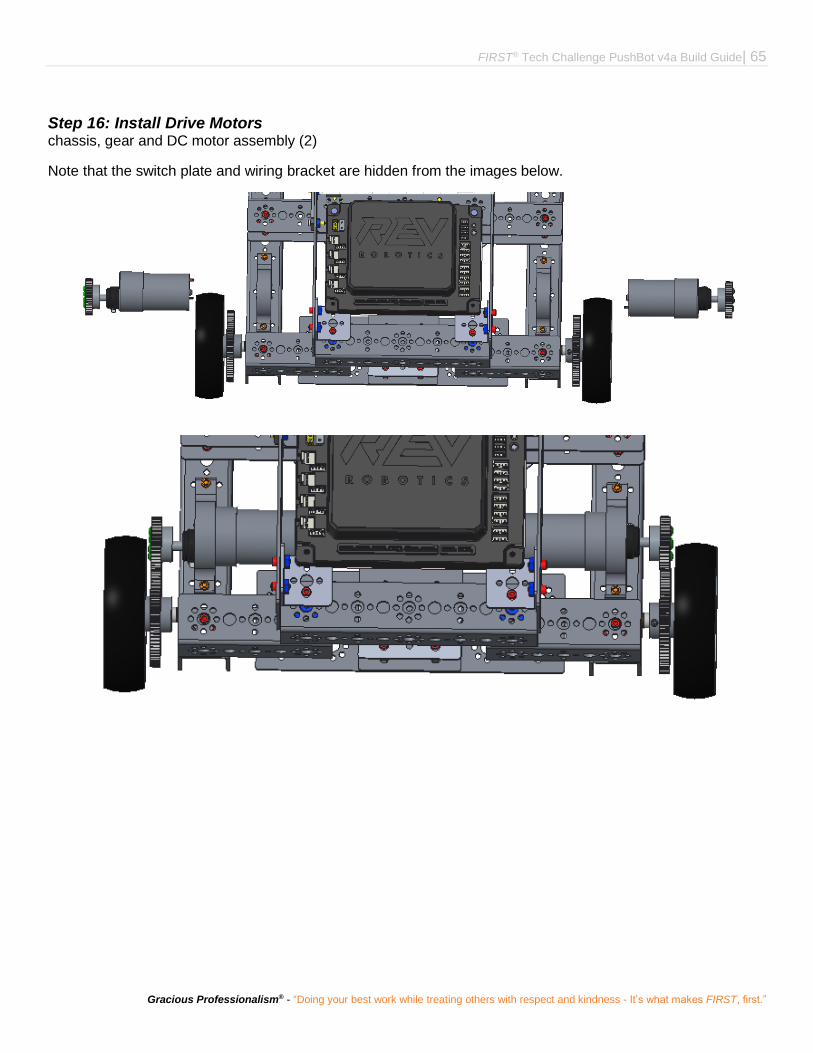
Step 16: Install Drive Motors chassis, gear and DC motor assembly (2)
Note that the switch plate and wiring bracket are hidden from the images below.
66 | FIRST® Tech Challenge PushBot v4a Build Guide
Revision 1: 9.13.2017
Electronics
This section will outline the installation of the electronics onto the chassis.
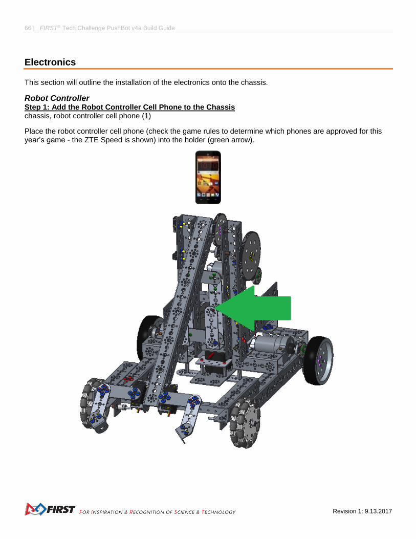
Robot Controller Step 1: Add the Robot Controller Cell Phone to the Chassis chassis, robot controller cell phone (1)
Place the robot controller cell phone (check the game rules to determine which phones are approved for this year’s game - the ZTE Speed is shown) into the holder (green arrow).

FIRST® Tech Challenge PushBot v4a Build Guide| 67
Gracious Professionalism® - “Doing your best work while treating others with respect and kindness - It’s what makes FIRST, first.”
Step 2: Connect the Phone to the USB Cable chassis, USB Type A male to type mini-B male cable (1)
Connect the mini-b end of the cable with the port on the phone.
Note: The phone is inside the phone holder, but the robot is not shown in the image below.
Step 3: Connect the USB Cable to the Micro USB OTG Adapter Cable chassis, micro USB OTG adapter cable (1)
Connect the USB end of the USB Type A male to type mini-B male cable with the USB end of the OTG adapter cable.
Note: The USB cable is attached to the phone, which is on the robot. This is not shown in the images below.

68 | FIRST® Tech Challenge PushBot v4a Build Guide
Revision 1: 9.13.2017
Step 4: Connect the Micro USB OTG Adapter Cable to the Expansion Hub chassis
Connect the micro USB end of the OTG adapter cable with the port on the expansion hub.
Note: The cable and expansion hub are on the robot. This is not shown in the images below.

FIRST® Tech Challenge PushBot v4a Build Guide| 69
Gracious Professionalism® - “Doing your best work while treating others with respect and kindness - It’s what makes FIRST, first.”
Servos Step 1: Servo Extension Wires to Servos Perform twice.
servo extension wires (2)
Connect the wire coming from the servo with the servo extension wire (the connector circled in green).
Note: Match the colors.
The image only shows one; make two.
Step 2: Servo Extension Wires to Expansion Hub chassis (with the now attached servo extension wires)
Run the extension wires down the center of the arm channel and over the axle to prevent damage to the wires.
Plug the left servo’s extension wire into the expansion hub’s servo port 0. Plug the right servo’s extension into the hub’s servo port 1.

70 | FIRST® Tech Challenge PushBot v4a Build Guide
Revision 1: 9.13.2017
Encoders Make two.
Step 1: Level Shifter Wires to Level Shifters level shifter wires (2), level shifters (2)
Connect the wires with the shifters.
The image only shows one; make two.

FIRST® Tech Challenge PushBot v4a Build Guide| 71
Gracious Professionalism® - “Doing your best work while treating others with respect and kindness - It’s what makes FIRST, first.”
Step 2: Level Shifters to Encoder Wires level shifter (2), encoder wire (2)
The image only shows one; make two.
Step 3: Level Shifter Wires to Expansion Hub chassis, level shifter wire assemblies (2)
Connect the end of one level shifter wire (circled in green) with port 0 of the expansion hub (indicated by a green arrow in the bottom image). Connect the other end (the encoder wire of the level shifter assembly) with the encoder on the left drive motor (not shown).
Connect the end of the other wire with port 1 of the expansion hub (indicated by a blue arrow in the bottom image). Connect the other end with the encoder on the right drive motor (not shown).
The above image only shows one assembly; use two.

72 | FIRST® Tech Challenge PushBot v4a Build Guide
Revision 1: 9.13.2017
DC Motors Step 1: Motor Power Cable to Extension Hub Cable Make two.
motor power cable (2), Anderson to JST VH cable (2)
Plug the end of one motor power cable (circled in green) into the Anderson power pole end (circled in green) of the Anderson to JST VH cable.
The images show only one of each cable; use twp.
Step 2: Motor Power Cable to Extension Hub Cable chassis, assemblies from the previous step
Connect the JST VH end (circled in green) of the Anderson to JST VH cable with port 0 of the expansion hub (indicated by a green arrow in the bottom image). Connect the other end (the DC motor wire of the cable assembly) into the DC motor on the left side of the robot (not shown).
Connect the JST VH end of a second wire assembly with port 1 of the expansion hub (indicated by a blue arrow in the bottom image). Connect the other end with the DC motor on the right side of the robot (not shown).
Connect the JST VH end of a third wire assembly with port 2 of the expansion hub (indicated by a yellow arrow in the bottom image). Connect the other end with the DC motor on the arm of the robot (not shown).

FIRST® Tech Challenge PushBot v4a Build Guide| 73
Gracious Professionalism® - “Doing your best work while treating others with respect and kindness - It’s what makes FIRST, first.”
Battery and Switch Step 1: Install Battery chassis, battery
Remove the battery support bracket by removing the two 5/16" socket head cap screws marked by the red arrows. Place the battery in the opening with the power cable end nearest to the front of the robot. Replace the battery support brace.

74 | FIRST® Tech Challenge PushBot v4a Build Guide
Revision 1: 9.13.2017
Step 2: Install Switch switch (1), chassis
Run the wires through the switch bracket, which is mounted on the left side panel. Plug the expansion hub end of the switch (green square) into the expansion hub (green square).

FIRST® Tech Challenge PushBot v4a Build Guide| 75
Gracious Professionalism® - “Doing your best work while treating others with respect and kindness - It’s what makes FIRST, first.”
Step 3: Connect the Switch to the Switch Adapter Cable chassis, Anderson Power Pole to XT30 Adapter (1)
Plug the XT30 end of the adapter into the switch wire - green squares.
Step 4: Connect the Battery to the Switch Adapter Cable chassis
Plug the Anderson Power Pole end of the adapter (green arrow) into the battery connector (green arrow).

76 | FIRST® Tech Challenge PushBot v4a Build Guide
Revision 1: 9.13.2017
Final Steps
The robot has been built, but that is only the beginning. Gear Trains need fine adjustments. Wires need to be secured. Programming will be needed to make the robot functional. Testing should be done to determine whether anything needs to be changed or optimized for the season’s game rules. It will also show whether more cables need to be secured or re-routed. Numbers and other stickers will be needed to make the robot competition ready. Check the game rules for all of the applicable stickers - usually the game rules include a self-inspection check list. USE THIS CHECK LIST BEFORE COMPETITION!
Visit the FIRST website for programming instructions and game rules.
Wiring Safety Additional zip ties should be purchased for securing wires to the chassis. The standard four-inch size works well for this. Also, electrical tape can be used to secure motor wires to the motor. Longer zip ties or Velcro straps can be used to keep the battery from falling out of the robot in case it tips over. Make sure that axle hub, motor hub, and axle collar set screws are installed, so that the screw is on the flat side of the axle, which will prevent assemblies from spinning on the axle.
Mesh Gears Properly The following pictures show examples of meshing the gears. The first is too loose; the second is too tight; the third (center below) is a good mesh. To test, rotate the mechanism by hand. If the gear teeth slip, then it is too loose. If the mechanism binds, then it is too tight.
Remember to tighten the motor mount bolt, so the motor will not rotate.

FIRST® Tech Challenge PushBot v4a Build Guide| 77
Gracious Professionalism® - “Doing your best work while treating others with respect and kindness - It’s what makes FIRST, first.”
Square the Frame Make sure that the frame is square. Once the frame is square, make sure that all of the frames bolts are tight. It is hard to drive a crooked robot straight!
Optimizing the Phone Holder It is recommended that an approved material such as non-skid be layered in the back of the phone holder to prevent damage to the phone.
It is recommended that the phone be secured in the holder using a zip tie or some other mechanism to prevent it from being separated from the robot during competition.
Optimizing the Battery Holder It is recommended that the battery be secured in the holder using a zip tie or some other mechanism to prevent it from being separated from the robot during competition.
Optimizing the Hand/Grippers Place non-skid around the gripper to provide extra grip…so hockey pucks, wiffle balls, pipes, racquetballs, crates, rings, blocks or practice golf balls, or red herrings can be collected with ease!
Add Team Numbers Usually team numbers need to be on both sides of the robot. Make them BIG. Make them easy to distinguish from other robots. Show off team numbers. They will be examined by many scouts while the robot is on the field. For further instructions, look at the Game Manual Part 1.

78 | FIRST® Tech Challenge PushBot v4a Build Guide
Revision 1: 9.13.2017
Appendix A – Resources
Game Forum Q&A http://ftcforum.usfirst.org/forum.php Anyone may view questions and answers within the FIRST® Tech Challenge Game Q&A forum without a password. To submit a new question, you must have a unique Q&A System User Name and Password for your team.
FIRST Tech Challenge Game Manuals Part 1 and 2 - http://www.firstinspires.org/node/4271
FIRST Headquarters Pre-Event Support Phone: 603-666-3906 Mon – Fri 8:30am – 5:00pm Email: [email protected]
FIRST Websites FIRST homepage – www.firstinspires.org
FIRST Tech Challenge Page – For everything FIRST Tech Challenge.
FIRST Tech Challenge Volunteer Resources – To access public Volunteer Manuals.
FIRST Tech Challenge Event Schedule – Find FIRST Tech Challenge events in your area.
FIRST Tech Challenge Social Media FIRST Tech Challenge Twitter Feed - If you are on Twitter, follow the FIRST Tech Challenge Twitter feed for news updates.
FIRST Tech Challenge Facebook page - If you are on Facebook, follow the FIRST Tech Challenge page for news updates.
FIRST Tech Challenge YouTube Channel – Contains training videos, Game animations, news clips, and more.
FIRST Tech Challenge Blog – Weekly articles for the FIRST Tech Challenge community, including Outstanding Volunteer Recognition!
FIRST Tech Challenge Team Email Blasts – contain the most recent FIRST Tech Challenge news for Teams.
FIRST Tech Challenge Google+ community - If you are on Google+, follow the FIRST Tech Challenge community for news updates.
Feedback We strive to create support materials that are the best they can be. If you have feedback about this manual, please email [email protected]. Thank you!

FIRST® Tech Challenge PushBot v4a Build Guide| 79
Gracious Professionalism® - “Doing your best work while treating others with respect and kindness - It’s what makes FIRST, first.”
Appendix B: Bill of Materials List
This list does not include the cell phones, the Rev Robotics Expansion Hub, nor the cables that connect the electronics.
Quantity Name Common Name
4 TETRIX_739068_2012 288 mm Channel
4 TETRIX_739067_2012 160 mm Channel
76 TETRIX_739098_2012 6-32 x 5/16” Socket Head Cap Screws
162 TETRIX_739094_2013 Kep Nuts
3 TETRIX_739065_2012 32 mm Channel
66 TETRIX_739097_2013 6-32 x 1/2” Socket Head Cap Screws
8 TETRIX_736466_HUB_2012 4” Omni Wheel
18 TETRIX_739091_2013 Bronze Bushing
11 TETRIX_739100_2012 1/8” Nylon Axle Spacer
8 TETRIX_739092_COLLAR_2012 Axle Set Collar
6 TETRIX_739088_2013 100 mm Axle
2 TETRIX_739101_2012 3/8” Nylon Axle Spacer
2 TETRIX_739055_2012 4” Tire/Wheel
2 TETRIX_739090_2012 Hub Gear Spacer
2 TETRIX_739086_2012 80-Tooth Gear
5 TETRIX_739172_COLLAR_2012 Axle Hub
4 TETRIX_739066_2012 96 mm Channel
1 TETRIX_739071_2012 288 mm Angle
1 TETRIX_739028_2012 40-Tooth Gear
2 TETRIX_739069_2012 416 mm Channel
4 TETRIX_739060_2012 Standard-Scale Servo Motor Brackets
4 TETRIX_739197_SERVO_2012 Standard-Scale HS-485HB Servo Motor
48 TETRIX_739111_2012 6-32 x 3/8” Button Head Cap Screws
6 TETRIX_739061_2012 Flat Bracket
6 TETRIX_739273_2013 96 mm Flat
5 TETRIX_739062_2012 L-Bracket
3 TETRIX_739272_2013 160 mm Flat
2 TETRIX_739270_2013 Inside C Connector
4 TETRIX_739281_CORNER_BRA_2013 Inside Corner Bracket
6 TETRIX_739102_2012 1” Stand-off Post
4 TETRIX_739073_2012 64 mm x 192 mm Flat Building Plate
2 TETRIX_738009_BATPACK_BRKT_2013 Battery Clip
1 TETRIX_739057_2012 12-Volt Rechargeable NiMH Battery Pack

80 | FIRST® Tech Challenge PushBot v4a Build Guide
Revision 1: 9.13.2017
1 ACRYLIC_SWITCH_BRACKET Power Switch Bracket
1 SWITCH Power Switch
Special Thanks and Best Wishes
We’d like to thank Mary and Laura Spangler for helping us finish this project. Mary stepped in at the last minute and helped with CREO while David was otherwise occupied. Laura made yummy peach ice cream and used that to help encourage us to finish.
We hope you have enjoyed the time you spent building your Push ‘Bot. If you have any questions or comments, please feel free to contact us at [email protected].
David and Lydean
www.ssi.lydean-david.net