2015 proposed changes - s3. · pdf filethe national standard plumbing code committee will...
TRANSCRIPT

National Standard Plumbing Code Committee __________________________________________________________
2015 PROPOSED
CHANGES National Standard
Plumbing Code (NSPC)
_____________________________________ July 23, 2014
Tropicana Casino and Resort Brighton and the Boardwalk Atlantic City, New Jersey
_________________________________________________________________________________________________
180 S. Washington St. Falls Church, VA 22046
1-800-533-7694, Fax: 703-237-7442, e-mail: [email protected], URL: http://www.phccweb.org/nspc

a

National Standard Plumbing Code Committee
180 S. Washington St. Falls Church, VA 22046 1-800-533-7694, Fax: 703-237-7442, e-mail: [email protected], URL: http://www.phccweb.org/nspc
The National Standard Plumbing Code Committee will conduct a Public Hearing on Proposed Changes to the Code. This Hearing will be held July 23, 2014 at the Tropicana Casino and Resort in Atlantic City, New Jersey. The public is invited to attend and comment will be allowed on the Proposed Changes. Adopted changes shall be published in the 2015 National Standard Plumbing Code. A continental breakfast will be served in the Mambo Room prior to the 8:00 A.M. start of the Public Hearing. A lunch break will be called at noon, attendees shall be responsible for their own lunch expenses. The meeting will reconvene at 1:00 P.M. or as directed by the Chairman. An afternoon break will be provided with the meeting scheduled to conclude at 5:00 P.M.
Hotel accommodations are available through the Tropicana Casino and Resort, mention the Plumbing-Heating-Cooling Contractors—National Association meeting for group rate availability. The hotel may be contacted by calling 800-247-8767.
The Proposed Changes are available to download from the PHCC—National Association website, phccweb.org, for review. Hard copy of the Proposed Changes book shall be available at the Hearing location.
For questions or further information, contact Charles White, Code Secretariat, at 800-533-7694 or by e-mail, [email protected].

a

National Standard Plumbing Code Committee
180 S. Washington St. Falls Church, VA 22046 1-800-533-7694, Fax: 703-237-7442, e-mail: [email protected], URL: http://www.phccweb.org/nspc
HOTEL INFORMATION
A block of rooms has been secured at the Tropicana Casino and Resort, Brighton and the Boardwalk, Atlantic City, New Jersey. Rooms are available for $85.00 per night plus 14% tax and $10 resort fee. Check in is 4:00 P.M., parking is $10.00 per day or $15.00 Valet. Please contact the hotel to make your reservation, you must mention the Plumbing-Heating-Cooling Contractors—National Association meeting to receive this rate. Cutoff date for reservations is June 30, 2014. Guaranteed rooms will be held until 10:00 P.M. on the night of arrival. Rooms must be cancelled 48 hours in advance to avoid one nights charge. Contact the Tropicana Casino and Resort at 800-247-8767 to make your reservations. DIRECTIONS From New York Take the New Jersey Turnpike to the Garden State Parkway (Exit 11). Proceed south on the Parkway to Exit 38 (Atlantic City Expressway). Take the Atlantic City Expressway east. At the base of the Atlantic City Expressway, take Exit 2 and follow signs to Tropicana Casino and Resort, Home of The Quarter. Continue straight onto Albany Avenue. Turn left onto Atlantic Avenue. Turn right at S. Brighton Avenue. From Philadelphia Cross the Benjamin Franklin Bridge or Walt Whitman Bridge and follow the North-South Freeway (Route 42) to the Atlantic City Expressway. Take Atlantic City Expressway east. At the base of the Atlantic City Expressway, take Exit 2 and follow signs to Tropicana Casino and Resort, Home of The Quarter. Continue straight onto Albany Avenue. Turn left onto Atlantic Avenue. Turn right at S. Brighton Avenue. From Baltimore/Washington D.C. Take I-95 North across the Delaware Memorial Bridge and follow Route 40 east to the Atlantic City Expressway. Take the Atlantic City Expressway east. At the base of the Atlantic City Expressway, take Exit 2 and follow signs to Tropicana Casino and Resort, Home of The Quarter. Continue straight onto Albany Avenue. Turn left onto Atlantic Avenue. Turn right at S. Brighton Avenue.

a

National Standard Plumbing Code Committee
2013 National Standard Plumbing Code Committee
180 S. Washington St. Falls Church, VA 22046 1-800-533-7694, Fax: 703-237-7442, e-mail: [email protected], URL: http://www.phccweb.org/nspc
J. Richard Wagner, PE Chairman, NSPC Committee Charles Chalk Maryland PHCC James Galvin Plumbing Manufacturers International John Heine New Jersey PHCC Leon LaFreniere City of Manchester, NH Dept. of Buildings Frank R. Maddalon F. R. Maddalon Plumbing & Heating Michael Maloney Plumbers & Pipefitters Local #9 Thomas C. Pitcherello NJ Department of Community Affairs Codes Assistance Unit
Luis A. Rodriguez, CPD, LEED AP KSi Professional Engineers Ronald W. Stiegler Maryland PHCC Kevin Tindall PHCC Executive Committee Liaison Alex Tucciarone Old Bridge Plumbing Inspector Jerry Van Pelt, CIPE GVP Consulting, LLC Charles R. White Secretariat & Staff Liaison Plumbing-Heating-Cooling Contractors–National Association e-mail: [email protected]

a

National Standard Plumbing Code Committee
180 S. Washington St. Falls Church, VA 22046 1-800-533-7694, Fax: 703-237-7442, e-mail: [email protected], URL: http://www.phccweb.org/nspc
THREE YEAR CYCLE
2014 April 30 Cutoff for 2015 Proposed Changes July 23 Committee Meeting & Pubic Hearing December Publish 2015 NSPC
2015 October 31 Cutoff for Proposed Changes December Committee Meeting 2016 Supplement to NSPC
2016 March Committee Meeting & Public Hearing May Publish 2016 Supplement to NSPC December Cutoff for Proposed Changes 2018 NSPC
2017 March Committee Meeting July Committee Meeting & Public Hearing December Publish 2018 NSPC
2018 December Cutoff for Proposed Changes 2020 Supplement
2019 March Committee Meeting July Committee Meeting & Public Hearing September Publish Supplement to 2018 NSPC
2020 March Cutoff for Proposed Changes 2021 NSPC May Committee Meeting September Committee Meeting & Public Hearing
2021 January Publish 2021 NSPC

a

Item # Section Number Person Submitting Change Committee Action
2013 SupplementTabled Items
13-25 Section 3.4.6 Limits on Lead NSPC Committee
13-63 Table 3.1.3 - Part XI NSPC Committee
13-65 Table 3.1.3 - Part XI NSPC Committee
13-77 Table 3.4.3 PP NSPC Committee
13-86 4.2.14.5 Heat Fusion Joints NSPC Committee
13-91A Table 5.2 NSPC Committee
13-100 5.5.1.d Exception NSPC Committee
13-111 7.4.4 & 7.4.9 Water Closets NSPC Committee
13-118 Section 7.10.4 NSPC Committee
13-121 Drinking Water Facilities NSPC Committee
13-125 7.16.4 Required Locations for Floor Drains NSPC Committee
13-126 7.16.4 a Floor Drains in Toilet Rooms NSPC Committee
13-129 7.21.5 c Laundry Trays NSPC Committee
13-173 10.15.2 c NSPC Committee
13-177 10.15.6 j NSPC Committee
13-179 10.15.6 Mixed Water Update NSPC Committee
13-187 10.16.7 Water Heater Vacuum Relief NSPC Committee
13-190 10.20.2 f Lead Free NSPC Committee
Matrix of changes for the2015 National Standard Plumbing Code
July 23, 2014

Item # Section Number Person Submitting Change Committee Action
13-192 10.20.4 NSPC Committee
13-194 10.20.4 d Lead Free NSPC Committee
13-195 10.20.8 ASSE 7010 NSPC Committee
13-195a Table 11.4.1 Shower Stall DFU's NSPC Committee
13-203 12.4.1 b Vent Terminals NSPC Committee
13-20713.1.1 Where Required
NSPC Committee
13-213 15.3 Leak Testing NSPC Committee
13-214 15.3.2 Exception NSPC Committee
2015 NSPC Proposed Changes
14-1 1.2 Adopting Agency & AHJ NSPC Committee
14-2 1.2 Backflow Definitions NSPC Committee
14-3 1.2 Compensating Valves NSPC Committee
14-4 1.2 Deleted Definitions NSPC Committee
14-5 1.2 Local Ventilating Pipe NSPC Committee
14-6 1.2 Revised Definitions NSPC Committee
14-7 1.2 RP Backflow Preventer NSPC Committee
14-8 1.2 Sewage & Waste NSPC Committee
14-9 1.2 Sewage Pump NSPC Committee
14-10 1.2 Stack NSPC Committee
14-11 1.2 Storm Drains NSPC Committee
14-12 2.3.1 Uses for Drainage Fittings Donald Jones
14-13 2.4.3 Obstruction to Flow Ron George

Item # Section Number Person Submitting Change Committee Action
14-14 2.4.5 Accessible Joints NSPC Committee
14-15 2.6.3 Initial Back-fill NSPC Committee
14-16 2.9 Pipe Protection NSPC Committee
14-17 2.23 Dead Ends NSPC Committee
14-18 2.25.5 Sanitary Floor Sinks NSPC Committee
14-19 2.26 Elevator Pits NSPC Committee
14-20 2.30 Swimming Pools NSPC Committee
14-21 Table 3.1.3 Update (Parts I - XI) NSPC Committee
14-22 Tables 3.1.3, 3.5, 3.7 ASTM D2751 NSPC Committee
14-23 3.3.8 c Pressure Tanks and Vessels Donald Jones
14-24 Table 3.4 Updates NSPC Committee
14-25 Table 3.4 ASTM D2672 NSPC Committee
14-26 3.4.1.2 Stainless Steel Nick Azmo
14-27 Table 3.4.2 ASTM D3035 ASTM F714 NSPC Committee
14-28 Table 3.4.2 Updates NSPC Committee
14-29 3.4.6 Limits on Lead NSPC Committee
14-30 Tables 3.5 - 3.7 ASTM F1760 NSPC Committee
14-31 Tables 3.5 - 3.8 Updates NSPC Committee
14-32 4.2.11.2 Mechanical Daniel O'Gorman
14-33 4.2.14.5 AWWA C906 NSPC Committee
14-34 4.2.14.6 ASTM F1498 NSPC Committee
14-35 4.2.15 Slip Joints Pete Hammer

Item # Section Number Person Submitting Change Committee Action
14-36 4.2.18 Heat Fusion NSPC Committee
14-37 4.3.8 Aboveground/Underground NSPC Committee
14-38 4.3.8 Joints Daniel O'Gorman
14-39 5.1 Separate Traps for Each Fixture Ron George
14-40 5.3 General Requirements for Traps Ron George
14-41 5.3.7 Drum Trap Solids Interceptors NSPC Committee
14-42 5.4.6 Installation of Cleanouts NSPC Committee
14-43 5.5.1.d Backwater Valves NSPC Committee
14-44 6.1 & 6.2 AHJ NSPC Committee
14-45 7.2 Accessibility Standards NSPC Committee
14-46 7.3.5 Wall-hung Supports NSPC Committee
14-47 7.4.4 Delete WC Accessibility NSPC Committee
14-48 7.4.8 Water Closets with Pumps NSPC Committee
14-49 7.5.1 Urinals NSPC Committee
14-50 7.6.1 Lavatory Air Gaps NSPC Committee
14-51 7.6.5 Wash Fountains NSPC Committee
14-52 7.8.2 Waste and Overflow NSPC Committee
14-53 7.8.4 Bathtub Backflow NSPC Committee
14-54 7.9 Whirlpool Baths NSPC Committee
14-55 7.10.4 Shower Outlets NSPC Committee
14-56 7.10.6 Shower Pan Test NSPC Committee
14-57 7.11 Sinks NSPC Committee

Item # Section Number Person Submitting Change Committee Action
14-58 7.12 Drinking Water Facilities NSPC Committee
14-59 7.15.1 ASSE 1021 NSPC Committee
14-60 7.16 Floor Drains NSPC Committee
14-61 7.18.1 Special Installations NSPC Committee
14-62 7.19 CSA B125.3 NSPC Committee
14-63 7.21 Required Plumbing Fixtures NSPC Committee
14-64 7.21.6.e Hand Washing Facilities NSPC Committee
14-65 7.21.6 e Hand Washing Facilities Michael Baker
14-66 7.22 ref 10.18.1 NSPC Committee
14-67 7.24 Emergency Eyewash NSPC Committee
14-68 Chapter 8 Miscellaneous NSPC Committee
14-69 9.1.3 Air Breaks NSPC Committee
14-70 10.1 Potable Water Supply NSPC Committee
14-71 10.5.1 Air Gaps NSPC Committee
14-72 10.5.5.b Urinal Vacuum Breakers NSPC Committee
14-73 10.5.6 Backflow Certification NSPC Committee
14-74 10.5.14 Backflow Matrixes Nick Azmo
14-75 Table 10.8.3 Overflow Pipes NSPC Committee
14-76 10.12 Shutoff Valves NSPC Committee
14-77 10.12.2 Building Valve NSPC Committee
14-78 10.12.4 Dwelling Units NSPC Committee
14-79 10.13 CSA B125.6 NSPC Committee

Item # Section Number Person Submitting Change Committee Action
14-80 10.14.7 and 10.16.7 NSPC Committee
14-81 10.15.1 Hot Water Supply NSPC Committee
14-82 10.15.2 Hot Water Temp Maintenance NSPC Committee
14-83 10.15.2c Recirculation Greg Towsley
14-84 10.15.6 Mixed Water Temperature Control NSPC Committee
14-85 10.15.6 Hand Washing NSPC Committee
14-86 10.15.7 Thermal Expansion Control NSPC Committee
14-87 10.15.9.3 Drainage Michael Baker
14-88 10.15.11 Domestic HW Heaters NSPC Committee
14-89 10.16.3 Temperature Relief Valve NSPC Committee
14-90 10.16.3 Temperature Relief Valve Donald Jones
14-91 10.16.6 Relief Valve Discharge Piping NSPC Committee
14-92 10.16.6 Relief Valve Discharge Piping Ron Barbarulo
14-93 10.20.8 ASSE 7010 NSPC Committee
14-94 Table 11.4.1 GPM to DFU NSPC Committee
14-95 11.4.4 Floor Drains NSPC Committee
14-96 11.5.2 Drain Stack Sizing NSPC Committee
14-97 11.5.3 Branch Drains NSPC Committee
14-98 11.6 Effect of Offsets NSPC Committee
14-99 11.6.3 Length of Stack Vents NSPC Committee
14-100 11.7.4 Pneumatic Ejectors NSPC Committee
14-101 11.7.6 ASME/CSA NSPC Committee

Item # Section Number Person Submitting Change Committee Action
14-102 11.9 Base of Stack Connections NSPC Committee
14-103 12.3.1 Venting Drain Stacks NSPC Committee
14-104 12.6.1 Vent Slope NSPC Committee
14-105 12.8.2 Future Vent NSPC Committee
14-106 12.8.2 Aggregate Size of Vent Daniel O'Gorman
14-107 12.13 Battery Venting NSPC Committee
14-108 12.14 Subdrain Sump Pumps NSPC Committee
14-109 Table 12.16 (2012) NSPC Committee
14-110 12.16.4 Size Vents NSPC Committee
14-111 13.1.6 Draining Areaways NSPC Committee
14-112 13.1.9 Trench Drains NSPC Committee
14-113 13.1.13 Water-operated Sump Pumps NSPC Committee
14-114 13.4.1 Improper Connections NSPC Committee
14-115 13.5 Roof Drains NSPC Committee
14-116 13.6 Sizing of Storm Drain Piping NSPC Committee
14-117 13.7 Area Drains and Trench Drains NSPC Committee
14-118 14.3.2 ASSE 6000 NSPC Committee
14-119 15.3 Testing NSPC Committee
14-120 Chapter 17 Private Systems NSPC Committee
14-121 17.9.1 Pitless Adapters NSPC Committee
14-122 18.1 Trailer Coach NSPC Committee
14-123 18.5.3 Trailer Parks NSPC Committee

Item # Section Number Person Submitting Change Committee Action
14-124 19.1, 19.2 Referenced Standards NSPC Committee
14-125 Appendix D - Examples A & B NSPC Committee
14-126 F.2 References NSPC Committee
14-127 Appendices H & J - delete NSPC Committee
14-128 Appendix J NSPC Committee

National Standard Plumbing Code Committee __________________________________________________________
2013 TABLED ITEMS
National Standard Plumbing Code (NSPC)
Proposed Code Changes
_________________________________________________________________________________________________
180 S. Washington St. Falls Church, VA 22046 1-800-533-7694, Fax: 703-237-7442, e-mail: [email protected], URL: http://www.phccweb.org/nspc


National Standard Plumbing Code 2012 Proposed Code Change Form Deadline September 27, 2012
13 - 25
Page 1 of 7
13-25
Contact Information: Person Submitting Change 2 ______NSPC Committee_________________ Date 3 __1-11-2013_______ Jurisdiction/Company/ Mailing Address _______________180 S. Washington Street, P.O. Box 6808 _____________________ City/State/Zip _________________Falls Church, VA 22046___________________________________ Phone _1-800-533-7694____ Fax _1-703-237-7442____ E-mail [email protected]_____________ Check All That Apply: _____ Amend section with this editorial change __X__ Change subsection to read as follows _____ Delete subsection and substitute as follows _____ Add new subsection to read as follows _____ Delete subsection without substitution Code Section: 3.4.6 Limits on Lead Content and related Sections 1.2 Lead Content
a. Material used in potable water supply systems, including piping, faucets, and valves, shall be "lead-free" as defined in the current Federal Law. b. Drinking water system components shall comply with the lead leachate requirements of NSF 61. Refer to Section 3.1.5 for components that are within the scope of NSF 61.
1.2 End-Use Device: A water supply device that dispenses potable water such as a faucet, drinking fountain, kitchen hot water dispenser, bathtub and/or shower faucet, shower head, flush valve, hose bibb, or supply connection to an appliance. 1.2 Lead-Free: “Lead-free” means containing not more than a weighted average of 0.25% lead for the wetted surfaces of pipes, tubes, fittings for pipes and tubes, plumbing supply fittings, and fixtures. "Lead-free" solder and flux contains no more than 0.2% lead. 1.2 Pipe or Tube Fitting: A piping component that connects sections of pipes or tubes, such as a coupling, elbow, reducer, tee, flange, union, or flexible connector. 1.2 Plumbing Supply Fitting: A piping component other than a pipe fitting or tube fitting that performs a required function in potable water supply piping such as a faucet, adapter, valve, strainer, filter, temperature limiting or control device, pressure switch, thermometer well, expansion compensator, or water hammer arrestor.

13-25
1.2 Weighted Average Lead Content: The weighted average lead content of a "lead-free" pipe, pipe fitting, plumbing fitting, or fixture shall be calculated by using the following formula: For each wetted component, the percentage of lead in the component shall be multiplied by the ratio of the wetted surface area of that component to the total wetted surface area of the entire product to arrive at the weighted percentage of lead of the component. The weighted percentage of lead of each wetted component shall be added together, and the sum of these weighted percentages shall constitute the weighted average lead content of the product. The lead content of the material used to produce wetted components shall be used to determine compliance with "lead-free". For lead content of materials that are provided as a range, the maximum content of the range shall be used. Table 3.1.3 - X. MISCELLANOUS:
21. Drinking Water System Components - Health Effects: NSF 61 - 2007 2011 22. Weighted Average Lead Content Evaluation Procedure to a 0.25% Lead Requirement NSF 61-Annex G - 2009. 23. Drinking Water System Components - Lead Content NSF 372 - 2010
3.1.5 Health Effects of Drinking Water Components a. The health effects of drinking water components shall comply with NSF 61. Components within the scope of NSF 61 have surfaces in contact with potable water. Components include, but are not limited to, plastic materials, plastic and metallic pipe, pipe-related products, protective materials, joining and sealing materials, process media, treatment devices, transmission devices, distribution devices, and end-point devices. b. Refer to Section 3.4.6 for the limit on the lead content of pipes, tubes, pipe fittings, tube fittings, plumbing supply fittings, fixtures, and end-use devices that are intended to dispense potable water for human consumption by drinking or cooking. 3.3.6 Plumbing Supply Fittings Reserved Plumbing supply fittings covered under the scope of NSF 61 shall comply with its requirements. Refer to Section 3.1.5 for components that are within the scope of NSF 61. 3.4 POTABLE WATER PIPING 3.4.1 Plastic Piping Plastic piping materials used for the conveyance of potable water shall comply with NSF 14 and be marked accordingly.

13-25
3.4.2 Water Service Piping Water service pipe and pipe fittings piping to the point of entrance into the building through a foundation wall or floor shall be of materials listed in Table 3.4 and shall be water pressure rated not less than 160 psig at 73 deg F. See Table 3.4.2. Water service pipe and fittings shall comply with NSF 61 Section 3.4.6 for the limits on lead content. 3.4.3 Water Distribution Piping Water piping for the distribution of hot or cold water within buildings shall be of material listed in Table 3.4, and shall be water pressure rated for not less than 100 psi at 180 deg F and 160 psi at 73 deg F. Plastic piping used in hot water distribution shall be installed in accordance with the requirements of Section 10.15.8. Water distribution pipe and pipe fittings shall comply with NSF 61 Section 3.4.6 for the limits on lead content. NOTE: The working pressure rating of certain approved plastic piping materials varies depending on the pipe size, material composition, wall thickness, and methods of joining. See Table 3.4.3. 3.4.4 Fittings a. Fittings for water supply piping shall be compatible with the pipe material used. b. Insert fittings for plastic tubing shall be the metallic or plastic type that comply with the standards listed in Table 3.1.3. 3.4.5 Material Ratings and Installation a. Piping used for domestic potable water shall be suitable for the maximum temperature, pressure, and velocity that may be encountered, including temporary increases and surges. b. Relief valve temperature and pressure relief settings shall not exceed the pipe, tubing tube or fitting manufacturer's recommendations. c. Pipe Piping and fittings shall be installed in accordance with the manufacturer's installation instructions and the acceptable material standards, recognizing any limitations in use. 3.4.6 Limit Limits on Lead Content a. Materials used in potable water supply systems, including piping, faucets and valves, shall be "lead-free" as defined by current Federal Law. b. Drinking water system components shall comply with the lead leachate requirements of NSF 61. Refer to Section 3.1.5 for components that are within the scope of NSF 61. a. Pipes, tubes, fittings for pipes and tubes, plumbing supply fittings, fixtures, and end-use devices that are intended to dispense potable water for human consumption by drinking and cooking shall be "lead-free", containing not more than a weighted average of 0.25% lead with respect to the wetted surfaces, as defined in Section 1.2 of this Code. b. Solder and flux for soldered joints in potable water piping shall be "lead-free", containing not more than 0.2% lead. Flux for making soldered joints in "lead-free" piping shall be rated for the temperatures necessary for making joints in "lead-free" piping.

13-25
c. Potable water supply components that are within the scope of NSF 61 for drinking water system components and are required to be "lead-free" shall be certified to comply with NSF 61 and either its Annex G or NSF 372. d. Potable water supply components that are not within the scope of NSF 61 for drinking water system components but are required to be "lead-free" shall be certified to comply with NSF 372. e. Potable water supply components that are not required to be "lead-free" shall be rated for use with potable water and shall not contain more than 4% lead by dry weight for plumbing supply fittings and fixtures or more than 8% lead by dry weight for pipes, tubes, and fittings for pipes and tubes. f. The following potable water end-use devices and water supply piping are considered to be intended to convey water for human consumption through drinking or cooking and shall be "lead-free", including their associated supply piping: 1. kitchen sink faucets 2. bar sink faucets 3. private bathroom sink faucets 4. drinking fountain faucets 5. kitchen hot water dispensers 6. point-of-use water treatment devices 7. the water supply to ice makers 8. the water supply to potable water heaters 9. recirculated hot water piping 10. the water supply to misting systems for produce in food markets 11. the water supply to cooking equipment for food in commercial kitchens 12. the water supply to production equipment for processed food containing water 13. any other end-use devices and piping that convey water for human consumption EXCEPTION: Tank-type water heaters shall not be required to be "lead-free" unless there is an industry standard for "lead-free" tank-type water heaters and they are required to be "lead-free" by the Authority Having Jurisdiction. g. The following piping components shall be "lead-free" when associated with "lead-free" end-use devices and piping that is required to be "lead-free:" 1. main service shutoff valves 2. water service backflow prevention devices 3. water meters 4. pressure booster pumps 5. pressure reducing valves 6. strainers 7. water filters 8. check valves 9. control valves 10. vacuum breakers 11. water hammer arrestors 12. master hot water mixing valves 13. in-line tempering valves 14. hot water recirculating pumps 15. branch piping shutoff valves

13-25
16. balancing valves 17. fixture shutoff valves 18. solenoid valves 19. tankless water heaters 20. any other piping components associated with end-use devices or piping that are required to
be "lead-free" h. The following potable water end-use devices, water supplies, and components are not considered to be intended to convey water for human consumption through drinking or cooking and are not required to be "lead-free", including their associated water supply piping, unless their associated piping also serves end-use devices and water supplies that must be "lead-free". 1. bathtub faucets 2. shower valves, heads, and adapters 3. tank-type water heaters 4. flush valves for water closets 5. flush valves for urinals 6. flush valves for bidets 7. shutoff valves for clothes washing machines 8. lavatory faucets in public toilet rooms 9. laundry sink faucets 10. service sink faucets 11. faucets for laboratory applications 12. hose bibbs 13. trap seal priming devices 14. backflow prevention devices that supply non-potable applications 15. fire hose valves 16. water hammer arresters 17. the water supply to dish washers 18. the water supply to whirlpools, spas, therapy pools, and swimming pools 19. the water supply to boilers and heating hot water generators 20. the water supply to humidifiers 21. the water supply to irrigation systems and other non-potable applications 22. the water supply to food production equipment that does not contact the food 23. any other end-use devices and water supplies that do not convey water for human
consumption EXCEPTION: Tank-type water heaters shall not be required to be "lead-free" unless there is an
industry standard for "lead-free" tank-type water heaters and they are required to be "lead-free" by Section 3.4.6, as dictated by the Authority Having Jurisdiction.
3.4.7 Shutoff Valves a. All gate valves, ball valves, butterfly valves, globe valves, and other shutoff valves in water service piping and water distribution piping shall comply with the requirements of NSF 61. that supply potable water for human consumption by drinking or cooking shall be "lead-free" in accordance with Section 3.4.6. b. Shutoff valves that must be "lead-free" and are within the scope of NSF 61 shall comply with the requirements of NSF 61 and either its Annex G or NSF 372.

13-25
c. Shutoff valves that must be "lead-free" but are not within the scope of NSF 61 shall comply with NSF 372. d. Shutoff valves that are not required to be "lead-free" shall be rated for use with potable water and shall not contain more than 4% lead by dry weight. Section 4.2.4 Soldered f. Flux for making soldered joints in "lead-free" piping shall be rated for the temperatures necessary for making joints in "lead-free" piping. 7.1 FIXTURE STANDARDS 7.1.1 General Plumbing fixtures, plumbing fixture trim, and plumbing appliances shall comply with the standards listed in Table 3.1.3. Plumbing supply fittings covered under the scope of NSF 61 shall comply with the requirements of NSF 61. 7.1.2 Fixture Faucets and other End-Use Devices a. Fixture faucets and other end-use devices that supply potable water for human consumption by drinking or cooking shall be "lead-free" in accordance with Section 3.4.6. b. Fixture faucets and other end-use devices that must be "lead-free" and are within the scope of NSF 61 shall comply with the requirements of NSF 61 and either its Annex G or NSF 372. c. Fixture faucets and other end-use devices that must be "lead-free" but are not within the scope of NSF 61 shall comply with NSF 372. d. Fixture faucets and other end-use devices that are not required to be "lead-free" shall be rated for use with potable water and shall not contain more than 4% lead. 10.1 QUALITY OF WATER SUPPLY a. Only potable water shall be supplied to plumbing fixtures used for drinking, bathing, culinary use, laundry use, cleaning, or the processing of food, medical, or pharmaceutical products. 10.20 NFPA 13D Multipurpose Residential Fire Sprinkler Systems 10.20.2 General f. NFPA 13D multipurpose piping systems shall comply with the "lead-free" requirements of this Code if the piping, including parallel looped branches, supplies one or more end-use devices or equipment that are required to be "lead-free" by Section 3.4.6. The fire sprinklers in such piping shall be "lead-free". EXCEPTIONS: (1) Sprinkler-only branch supply piping to one or more individual sprinklers.

13-25
(2) Sprinklers supplied by individual sprinkler-only branch piping. (3) Plumbing-only branch supply piping to end-use devices or equipment that are not required to
be "lead-free". 10.20.4 Materials for Combined System Piping d. Piping within combined piping systems that conveys water to outlets for human consumption by drinking or cooking shall be "lead-free" in accordance with Section 3.4.6. Basis/Reason for Change: To incorporate the requirements of the Safe Drinking Water Act for "lead-free" plumbing into the National Standard Plumbing Code. Vote: ___ Accept ___ Accept as Amended
___ Accept in Part ___ Accept in Principle ___ Accept in Part and Principle
___ Defeated ___Failed Lack of Second ___ Tabled ___ Withdrawn ___ Other __________________________________________________________________________________

National Standard Plumbing Code 2012 Proposed Code Change Form Deadline January 31, 2013
13 - 63
13-63
Contact Information: Person Submitting Change 2 __Steve Silber, International President – representing ASSE Code Committee_ Date 3 _1/29/2013______ Jurisdiction/Company/ Mailing Address __ASSE International, 901 Canterbury Road_____ City/State/Zip __Westlake, OH 44145_________________________________________ Phone _440-835-3040__ Fax _440-835-3488___ E-mail _____________________________ IMPORTANT: Please review the attached instruction sheet regarding proposed code changes. Check All That Apply: _____ Amend section with this editorial change _____ Change subsection to read as follows _____ Delete subsection and substitute as follows _X__ Add new subsection to read as follows _____ Delete subsection without substitution Code Section: __ Table 3.1.3 Part XI, Item TBD_____________ Add ASSE Series 7000-2008 with title Professional Qualifications Standard for Plumbing-Based Residential Fire Protection Systems Installers and Inspectors to Table 3.1.3, Part XI, Item TBD Basis/Reason for Change: ASSE Series 7000 is an ANSI Approved standard developed under the consensus process and establishes minimum criteria for installers and inspectors for fire protection systems in one-and two-family dwellings. Vote: ___ Accept ___ Accept as Amended
___ Accept in Part ___ Accept in Principle ___ Accept in Part and Principle
___ Defeated ___Failed Lack of Second ___ Tabled ___ Withdrawn ___ Other ____________________________________________________________________________________

National Standard Plumbing Code 2012 Proposed Code Change Form Deadline January 31, 2013
13 - 65
13-65
Contact Information: Person Submitting Change 2 __Steve Silber, International President – representing ASSE Code Committee___ Date 3 _1/29/2013______ Jurisdiction/Company/ Mailing Address __ASSE International, 901 Canterbury Road_______ City/State/Zip __Westlake, OH 44145_________________________________________ Phone _440-835-3040__ Fax _440-835-3488___ E-mail _____________________________ IMPORTANT: Please review the attached instruction sheet regarding proposed code changes. Check All That Apply: _____ Amend section with this editorial change _____ Change subsection to read as follows _____ Delete subsection and substitute as follows X___ Add new subsection to read as follows _____ Delete subsection without substitution Code Section: __ Table 3.1.3 Part XI, Item TBD_____________ Add ASSE/IAPMO/ANSI Series 10000-2010 with title Professional Qualifications Standard for Green Plumbing Systems Installers to Table 3.1.3, Part XI, Item TBD Basis/Reason for Change: ASSE/IAPMO/ANSI Series 10000 is an ANSI Approved standard developed under the consensus process and establishes the level of competency necessary for the installation of sustainable plumbing and mechanical systems and products to protect public health, safety and the environment. Vote: ___ Accept ___ Accept as Amended
___ Accept in Part ___ Accept in Principle ___ Accept in Part and Principle
___ Defeated ___Failed Lack of Second ___ Tabled ___ Withdrawn ___ Other ____________________________________________________________________________________

National Standard Plumbing Code 2012 Proposed Code Change Form Deadline September 27, 2012
13 - 77
13-77
Contact Information: Person Submitting Change 2 _____Michael Cudahy__________________ Date 3 ___Aug 25 2012____ Jurisdiction/Company/ Mailing Address Plastic Pipe and Fittings Association 800 Roosevelt Rd Bld C Ste 312__________ City/State/Zip __Glen Ellyn / IL / 60137 Phone ___630 363 7933______ Fax __630 858 654___ [email protected]_______ IMPORTANT: Please review the attached instruction sheet regarding proposed code changes. Check All That Apply: _____ Amend section with this editorial change __X__ Change subsection to read as follows _____ Delete subsection and substitute as follows _____ Add new subsection to read as follows _____ Delete subsection without substitution Code Section: _____Table 3.4.3 Plastic Hot and Cold Water Distribution Piping
PP (ASTM F2389) | PP | Metric SDR 7.4, 6, 5 | fusion welded | all sizes Basis/Reason for Change: PP made in metric dimensions and SDR 7.4, 6 and 5 wall thicknesses to ASTM F2389 is suitable for potable and hot and cold water systems. Per the standard, “This specification establishes the requirements for polypropylene (PP) piping system components such as pipe, fittings, valves, and manifolds used in water service lines, hot-and-cold water distribution, hydronic heating, and irrigation systems to transport industrial process fluids, effluents, slurries, municipal sewage, etc. The piping system components covered here are made to metric sizes and IPS schedule 80 sizes, and pressure rated for water service and distribution supply.” Vote: ___ Accept ___ Accept as Amended
___ Accept in Part ___ Accept in Principle ___ Accept in Part and Principle
___ Defeated ___Failed Lack of Second ___ Tabled ___ Withdrawn ___ Other ____________________________________________________________________________________

National Standard Plumbing Code 2012 Proposed Code Change Form Deadline September 27, 2012
13 - 86
13-86
Contact Information: Person Submitting Change 2 ______NSPC Committee_________________ Date 3 __9-25-2012_______ Jurisdiction/Company/ Mailing Address _______________180 S. Washington Street, P.O. Box 6808 _____________________ City/State/Zip _________________Falls Church, VA 22046___________________________________ Phone _1-800-533-7694____ Fax _1-703-237-7442____ E-mail [email protected]_____________ Check All That Apply: _____ Amend section with this editorial change __X__ Change subsection to read as follows _____ Delete subsection and substitute as follows _____ Add new subsection to read as follows _____ Delete subsection without substitution Code Section: 4.3 Types of Joints Between Different Piping Materials 4.3.8 Special Joints and Couplings for Drainage Piping f. Couplings installed aboveground shall include center stops. EXCEPTION EXCEPTIONS: (1) Slip-on repair couplings used for repair or rework. (2) Flexible drain couplings for different pipe sizes. Basis/Reason for Change: Flexible drain couplings do not have center stops because of the two different pipe sizes that are being joined. Vote: ___ Accept ___ Accept as Amended
___ Accept in Part ___ Accept in Principle ___ Accept in Part and Principle
___ Defeated ___Failed Lack of Second ___ Tabled ___ Withdrawn ___ Other __________________________________________________________________________________

National Standard Plumbing Code 2012 Proposed Code Change Form Deadline September 27, 2012
13 - 91a
13-91a
Contact Information: Person Submitting Change 2 ______NSPC Committee_________________ Date 3 ___1-31-2013______ Jurisdiction/Company/ Mailing Address _______________180 S. Washington Street, P.O. Box 6808 _____________________ City/State/Zip _________________Falls Church, VA 22046___________________________________ Phone _1-800-533-7694____ Fax _1-703-237-7442____ E-mail [email protected]_____________ Check All That Apply: _____ Amend section with this editorial change __X__ Change subsection to read as follows _____ Delete subsection and substitute as follows _____ Add new subsection to read as follows _____ Delete subsection without substitution Code Section: Table 5.2 MINIMUM SIZE OF NON-INTERGRAL TRAPS Plumbing Fixture Trap Size in inches Shower stall or shower drain (multiple shower heads) 2, 3, 4 (2) NOTES FOR TABLE 5.2 (2) See Section 7.10.4.b. Basis/Reason for Change: To make the Table agree with Section 7.10.4.b for multiple shower heads, which has requirements for 2" 3" and 4" drains. Vote: ___ Accept ___ Accept as Amended
___ Accept in Part ___ Accept in Principle ___ Accept in Part and Principle
___ Defeated ___Failed Lack of Second ___ Tabled ___ Withdrawn ___ Other __________________________________________________________________________________

National Standard Plumbing Code
2012 Proposed Code Change Form Deadline September 27, 2012
-
Contact Information: Person Submitting Change
2 __John Heine_____________________ Date
3 1/7/13
Jurisdiction/Company/
Mailing Address ______________________________________________________________________
City/State/Zip ________________________________________________________________________
Phone ___609-987-0500_______________ Fax _ 609-987-0511 E-mail [email protected]
IMPORTANT: Please review the attached instruction sheet regarding proposed code changes.
Check All That Apply: _____ Amend section with this editorial change
_____ Change subsection to read as follows _____ Delete subsection and substitute as follows
___X__ Add new subsection to read as follows ___ Delete subsection without substitution
Code Section: 5.5.1d Exception: Existing buildings shall be permitted to drain through a backwater valve that serves all the
fixtures in a building if the floor elevation that the fixtures are on is above the next upstream manhole
cover.
Basis/Reason for Change: Existing buildings that have experienced a sewage backup that was
caused by problems in an existing public sewer main should be allowed to install a backwater valve in
the main building drain or sewer to protect the property. This change would allow the installation of a
backwater valve in a system where the existing drainage system discharges to the public sewer at an
elevation below the top of the next upstream manhole without having to repipe an existing system where
the total system is discharging through a common drain.
Vote: ___ Accept ___ Accept as Amended
___ Accept in Part ___ Accept in Principle ___ Accept in Part and Principle
___ Defeated ___Failed Lack of Second ___ Tabled ___ Withdrawn ___ Other
____________________________________________________________________________________
NJ PHCC Code Committee, (Chairman) / PO Box 2067
Princeton, NJ 08543

National Standard Plumbing Code 2012 Proposed Code Change Form Deadline September 27, 2012
13 - 111
13-111
Contact Information: Person Submitting Change 2 ______NSPC Committee_________________ Date 3 ___11-19-2012_____ Jurisdiction/Company/ Mailing Address _______________180 S. Washington Street, P.O. Box 6808 _____________________ City/State/Zip _________________Falls Church, VA 22046___________________________________ Phone _1-800-533-7694____ Fax _1-703-237-7442____ E-mail [email protected]_____________ Check All That Apply: _____ Amend section with this editorial change __X__ Change subsection to read as follows _____ Delete subsection and substitute as follows __X__ Add new subsection to read as follows _____ Delete subsection without substitution Code Section: 7.4.4, 7.4.9, Table 7.4.9 7.4.4 Bowl Height The height of water closet bowls shall be a minimum of 13-1/2 inches 13-1/2 to 17 inches from the finished floor to the top of the rim. EXCEPTIONS EXCEPTION: (1) Bowls intended for children's use (5 years and younger) are permitted to be 9-1/2" to 10-1/2" high to the rim and juvenile use (6-12 years) are permitted to be 10-1/2" to 13-1/2" to the rim. (2) The height of bowls intended specifically for children's accessible use (12 years and younger) shall be such that the top of the rim is 11" to 17" above the floor and comply with Section 7.2. (3) The height of bowls intended for adult accessible use (13 years and older) shall be such that the top of the seat is 17" to 19" above the floor and comply with Section 7.2. 7.4.9 Water Closets for Accessible Use (a) Water closets for accessible use shall comply with Section 7.2. (b) For adult use (13 years and older): 1. The height of water closet bowls shall be such that the top of the seat is 17 to 19 inches above the finished floor.

13-111
2. Wheelchair accessible water closets shall be located so that their centerlines are 16 to 18 inches from a side wall or partition with a grab bar. 3. Ambulatory accessible water closets shall be located so that their centerlines are 17 to 19 inches from a side wall or partition with a grab bar. (c) For children's use, the toilet seat height and centerline to a side wall or partition with a grab bar shall be in accordance with Table 7.4.9.
Table 7.4.9 DIMENSIONS FOR ACCESSIBLE WATER CLOSETS FOR CHILDREN Dimension Ages
3 and 4 Years 5 thru 8 Years 9 thru 12 Years Seat Height above the Finished Floor 11" to 12" 12" to 15" 15" to 17" Centerline to a Side Wall (1) 12" 12" to 15" 15" to 18" NOTES FOR TABLE 7.4.9 (1) Clearance to a side wall or partition with a grab bar. Basis/Reason for Change: To update the requirements for accessible water closets in accordance with the 2010 ADA Standards for Accessible Design and ANSI/ICC A117.1 - Accessible and Usable Buildings and Facilities. Vote: ___ Accept ___ Accept as Amended
___ Accept in Part ___ Accept in Principle ___ Accept in Part and Principle
___ Defeated ___Failed Lack of Second ___ Tabled ___ Withdrawn ___ Other __________________________________________________________________________________

National Standard Plumbing Code 2012 Proposed Code Change Form Deadline January 31, 2013
13 - 118
Contact Information: Person Submitting Change 2 ______NSPC Committee_________________ Date 3 ___1-26-2013______ Jurisdiction/Company/ Mailing Address _______________180 S. Washington Street, P.O. Box 6808 _____________________ City/State/Zip _________________Falls Church, VA 22046___________________________________ Phone _1-800-533-7694____ Fax _1-703-237-7442____ E-mail [email protected]_____________ Check All That Apply: _____ Amend section with this editorial change __X__ Change subsection to read as follows _____ Delete subsection and substitute as follows _____ Add new subsection to read as follows _____ Delete subsection without substitution Code Section: 7.10.4 Shower Waste Outlets a. (No change) b. Showers with multiple shower heads shall have a 2" waste outlet pipe size for up to 10 5 gpm, a
3" waste outlet pipe size for up to 20 10 gpm, or a 4" waste outlet pipe size for up to 50 15 gpm. Multiple waste outlets shall be provided where necessary to handle the total water flow from the shower heads.
EXCEPTION: Bathtubs Combination bath/showers with multiple two 2.5 gpm shower heads. c. (No change) d. (No change) e. (No change) COMMENT: Increased waste outlet pipe sizes are not required for combination bath/showers with multiple shower heads because of the depth of bathtubs compared to possible overflow from shower pans. Basis/Reason for Change: To reduce the maximum water flow rates for showers having multiple shower heads from the maximum capacity of horizontal drain piping flowing half full to better coordinate the allowable drain flow rates with the revised DFU values for shower stalls in Table 11.4.1. Vote: ___ Accept ___ Accept as Amended
___ Accept in Part ___ Accept in Principle ___ Accept in Part and Principle
___ Defeated ___Failed Lack of Second ___ Tabled ___ Withdrawn ___ Other __________________________________________________________________________________

National Standard Plumbing Code 2012 Proposed Code Change Form Deadline September 27, 2012
13 - 121
13-121
Contact Information: Person Submitting Change 2 ______NSPC Committee_________________ Date 3 ___1-15-2013______ Mailing Address 180 S. Washington Street, P.O. Box 6808 City/State/Zip Falls Church, VA 22046 Phone _1-800-533-7694____ Fax _1-703-237-7442____ E-mail [email protected]_____________ Check All That Apply: _____ Amend section with this editorial change __X__ Change subsection to read as follows _____ Delete subsection and substitute as follows _____ Add new subsection to read as follows _____ Delete subsection without substitution Code Section: 7.12 Drinking Fountains and Water Coolers Drinking Water Facilities 7.12.1 Compliance Refrigerated drinking fountains and water coolers shall comply with ARI 1010 and UL 399. 7.12.2 Prohibited Locations Drinking fountains and water coolers shall not be located in public toilet rooms. EXCEPTION: Convertible lavatory faucets and fixture fittings that provide a discharge stream similar to a drinking fountain shall be permitted in bathrooms in dwelling units. 7.12.3 Outdoor Drinking Fountains Freeze-resistant drinking fountains shall be the sanitary type. Weep hole drains that form a cross connection between ground water and the potable water supply shall not be permitted. 7.12.1 Compliance a. Drinking water facilities shall comply with the lead limits of NSF 61. b. Drinking water facilities for accessible use shall comply with Section 7.2. c. Drinking fountains shall comply with ASME A112.19.1/CSA B45.2, ASME A112.19.2/CSA B45.1, ASME A112.19.3/CSA B45.4, or ASME A112.19.9. d. Drinking water coolers with self-contained refrigeration units shall comply with UL 399 and ASHRAE Standard 18. e. Water bottle filling stations shall comply with applicable standards. Stations with self-contained refrigeration units for chilled water shall comply with UL 399 and ASHRAE Standard 18. 7.12.2 Prohibited Locations Drinking water facilities shall not be located in public toilet rooms. EXCEPTION: Convertible lavatory faucets that provide a discharge stream similar to a drinking fountain shall only be permitted in bathrooms in dwelling units.

13-121
7.12.3 Minimum Number of Required Facilities a. The minimum number of drinking water facilities shall be in accordance with Table 7.21.1. EXCEPTIONS: (1) No fewer than two drinking water facilities shall be provided, one for accessible wheelchair use and one for standing persons. (2) Where a drinking water facility provides service for two people simultaneously, one for accessible wheelchair use and one for standing persons, it may be counted as two drinking water facilities. b. Water bottle filling stations shall be permitted to substitute for up to 50% of the required drinking water facilities. c. Bottled water dispensers shall not be permitted to substitute for required drinking water facilities. 7.12.4 Outdoor Drinking Fountains Freeze-resistant drinking fountains shall be the sanitary type. Weep hole drains that form a cross connection between ground water and the potable water supply shall not be permitted. Section 1.2 Definition of Terms Water Bottle Filling Station: A drinking water supply fixture that is connected to the domestic water supply and drain piping and provides for individuals to fill personal-use water bottles. Stations can be recessed or wall-mounted and can include filtration units, self-contained refrigeration units, and drinking fountains. Table 3.1.3 - Part V V-4: Drinking Fountains and Water Coolers, Self-Contained, Mechanically Refrigerated: Drinking-Water Coolers ARI 1010-2002, UL 399 Edition 7 - 2008 UL 399 Ed.7 - 2008 (2012) V-15: Reserved Methods of Testing for Rating Drinking-Water Coolers with Self-Contained Mechanical Refrigeration…………………………………..…ASHRAE Standard 18 - 2008. Basis/Reason for Change: To update the requirements for drinking water facilities. Bottled water dispensers with no plumbing are not considered to be permanent and can be removed after building occupancy. Water bottle filling stations are popular in colleges and other facilities were people carry personal water bottles during the day. Their use reduces the use of bottled water dispensers and the number of used bottled water containers that end up in landfills. ARI 1010 has been withdrawn. Vote: ___ Accept ___ Accept as Amended
___ Accept in Part ___ Accept in Principle ___ Accept in Part and Principle
___ Defeated ___Failed Lack of Second ___ Tabled ___ Withdrawn ___ Other __________________________________________________________________________________

National Standard Plumbing Code 2012 Proposed Code Change Form Deadline September 27, 2012
13 - 125
13-125
Contact Information: Person Submitting Change 2 Dan O’Gorman Date 3 January 27, 2013 Jurisdiction/Company/ Mailing Address 10 Albany Street City/State/Zip Edison, New Jersey 08837 Phone 732-661-1935 Fax 732-661-9326 E-mail [email protected] IMPORTANT: Please review the attached instruction sheet regarding proposed code changes. Check All That Apply: _____ Amend section with this editorial change X Change subsection to read as follows _____ Delete subsection and substitute as follows _____ Add new subsection to read as follows _____ Delete subsection without substitution Code Section: 7.16.4 Required Locations for floor Drains 3. Common laundry rooms in commercial buildings and buildings having more two dwelling units Basis/Reason for Change: To clarity floor drains are not required in individual units and are required for common laundry rooms in commercial and other than dwelling units (condominiums and apartments) Vote: ___ Accept ___ Accept as Amended
___ Accept in Part ___ Accept in Principle ___ Accept in Part and Principle
___ Defeated ___Failed Lack of Second ___ Tabled ___ Withdrawn ___ Other ____________________________________________________________________________________

National Standard Plumbing Code 2012 Proposed Code Change Form Deadline September 27, 2012
13 - 126
13-126
Contact Information: Person Submitting Change 2 ______NSPC Committee_________________ Date 3 __9-24-2012_______ Jurisdiction/Company/ Mailing Address _______________180 S. Washington Street, P.O. Box 6808 _____________________ City/State/Zip _________________Falls Church, VA 22046___________________________________ Phone _1-800-533-7694____ Fax _1-703-237-7442____ E-mail [email protected]_____________ Check All That Apply: _____ Amend section with this editorial change __X__ Change subsection to read as follows _____ Delete subsection and substitute as follows _____ Add new subsection to read as follows _____ Delete subsection without substitution Code Section: 7.16 Floor and Trench Drains
7.16.4 Required Locations for Floor Drains a. Floor drains shall be installed in the following areas: 1. Toilet rooms containing either two or more water closets or wall hung urinals or a
combination of one or more water closets and one or more wall hung urinals, except in a dwelling unit.
2. Commercial kitchens. 3. Common laundry rooms in commercial buildings and buildings having more than two
dwelling units. Basis/Reason for Change: To clarify the requirements for floor drains in toilet rooms. Vote: ___ Accept ___ Accept as Amended
___ Accept in Part ___ Accept in Principle ___ Accept in Part and Principle
___ Defeated ___Failed Lack of Second ___ Tabled ___ Withdrawn ___ Other __________________________________________________________________________________

National Standard Plumbing Code 2012 Proposed Code Change Form Deadline September 27, 2012
13 - 129
13-129
Contact Information: Person Submitting Change 2 ______NSPC Committee_________________ Date 3 ____1-18-2012_____ Jurisdiction/Company/ Mailing Address _______________180 S. Washington Street, P.O. Box 6808 _____________________ City/State/Zip _________________Falls Church, VA 22046___________________________________ Phone _1-800-533-7694____ Fax _1-703-237-7442____ E-mail [email protected]_____________ Check All That Apply: _____ Amend section with this editorial change __X__ Change subsection to read as follows _____ Delete subsection and substitute as follows _____ Add new subsection to read as follows _____ Delete subsection without substitution Code Section: 7.21.5.c 7.21.5.c Laundry Trays: Multiple dwelling units or boarding houses without public laundry rooms shall not require laundry trays. Provisions for Clothes Washers: Apartment buildings and condominiums without laundry rooms for their occupants shall not require provisions for centralized clothes washers for use by multiple occupants. Basis/Reason for Change: To coordinate Section 7.21.5.c with the proposed changes to Table 7.21.1 with regard to provisions for clothes washers for multiple occupants in apartment buildings and condominiums. Vote: ___ Accept ___ Accept as Amended
___ Accept in Part ___ Accept in Principle ___ Accept in Part and Principle
___ Defeated ___Failed Lack of Second ___ Tabled ___ Withdrawn ___ Other __________________________________________________________________________________

National Standard Plumbing Code 2012 Proposed Code Change Form Deadline January 31, 2013
13 - 173
13-173
Contact Information: Person Submitting Change 2 ____Greg Towsley_________________ Date 3 ___22 January 2013_____ Jurisdiction/Company/ Mailing Address _____Grundfos, 17100 W 118th Terrace______________________________________ City/State/Zip ____Olathe, KS 66061_____________________________________________________ Phone __913-227-3414___ Fax _559-346-6414_______ E-mail [email protected]__________ IMPORTANT: Please review the attached instruction sheet regarding proposed code changes. Check All That Apply: _____ Amend section with this editorial change __x__ Change subsection to read as follows _____ Delete subsection and substitute as follows _____ Add new subsection to read as follows _____ Delete subsection without substitution Code Section: ___10.15.2.c________________________ THE FOLLOWING AMENDMENT IS SUBMITTED: NSPC Section 10.15.2.c: c. An on-demand recirculation system, activated by sensors or manually operated buttons, shall be permitted to be used tTo satisfy the requirements of Section 10.15.2a., the controls for the pumps in heated water distribution systems shall start the pump based on the identification of a demand for heated water within the occupancy. The controls shall automatically turn off the pump when the water in the circulation loop is at the desired temperature and when there is no demand for hot water. Basis/Reason for Change: The terminology of “on-demand recirculation system” is considered somewhat specific towards one manufacturer’s existing technology. US Patent No. 5829475 is for “On-demand zone valve recirculation system”. In addition, another manufacturer markets and promotes the same licensed solution for “On-Demand” Systems. Finally, Merriam-Webster dictionary does not recognize “on-demand” as a word. The above modified wording provides the same required control sequence with no reference to a manufacturers’ solution which may provide a market advantage. In addition, the proposed wording also opens up opportunities for future technologies to be developed. Vote: ___ Accept ___ Accept as Amended
___ Accept in Part ___ Accept in Principle ___ Accept in Part and Principle
___ Defeated ___Failed Lack of Second ___ Tabled ___ Withdrawn ___ Other ____________________________________________________________________________________


National Standard Plumbing Code 2012 Proposed Code Change Form Deadline January 31, 2013
13 - 179
13-179
Contact Information: Person Submitting Change 2 ______NSPC Committee________________ Date 3 ____1-11-2013 Jurisdiction/Company/ Mailing Address _________180 S. Washington Street, P.O. Box 6808 _____________________ City/State/Zip Falls Church, VA 22046___________________________________ Phone_1-800-533-7694____Fax_1-703-237-7442____E-mail [email protected] Check All That Apply: _____ Amend section with this editorial change __X__ Change subsection to read as follows _____ Delete subsection and substitute as follows _____ Add new subsection to read as follows_____ Delete subsection without substitution Code Section: 10.15.6 Mixed Water Temperature Control l. a. The temperature control devices for water heaters and other hot water supply sources shall not be permitted to be used to meet this Section's requirements for mixed water temperature control. b. Inlet Water Temperatures: The inlet hot and cold water temperatures for temperature actuated mixing valves shall be within their operating ranges and have sufficient differential above and below their discharge set point. f. c. Temperature Actuated Mixing Valves: Where temperature-actuated mixing valves are installed to control the in-line hot water supply temperature in the water distribution system, they shall comply with ASSE 1017. Such devices shall be installed at the hot water source and alone shall not supersede the other requirements of Section 10.15.6 for mixed water temperature control. a. d. Showers and Bath/Shower Combinations: All showers and bath/shower combinations shall be provided with individual balanced pressure, thermostatic, or combination automatic compensating valves that comply with ASSE 1016 or ASME A112.18.1/CSA B125.1. These valves shall include a means to limit the maximum discharge temperature of the water and shall be installed and field-adjusted in accordance with the manufacturer's instructions to a temperature no higher than 120°F. No further mixing of water shall be permitted downstream of the automatic compensating valve. e. EXCEPTION: Gang Showers: Where multiple gang showers are supplied by a one-pipe tempered water distribution system, the tempered water distribution shall be controlled by an automatic temperature control mixing valve complying with ASSE 1069. These valves shall include a means to limit the maximum discharge temperature of the water and shall be installed

13-179
and field-adjusted in accordance with the manufacturer's instructions to a temperature no higher than 105°F. No further mixing of water shall be permitted downstream of the automatic temperature control mixing valve. b. f. Bathtubs and Whirlpool Baths: The water discharged into bathtubs and whirlpool baths, with or without deck-mounted hand sprays, shall be controlled to a temperature no higher than 120°F by a water temperature limiting device complying with ASSE 1070, CSA B125.3, or ASSE 1016. c. g. Bidets: The hot water supply to the faucet on bidet plumbing fixtures shall be limited to 110°F by water temperature limiting device complying with ASSE 1070. Where bidets are incorporated into toilet seats or consist of a heated water tank and nozzle, their controls shall limit the discharge temperature to no more than 110°F. d. h. Public-Use Hand Washing Facilities: Water discharged from public-use hand washing facilities in public toilet rooms, hotel and motel guest rooms, and hospital patient rooms shall be limited to a temperature no higher than 110°F. Water temperature limiting devices serving one or more fixtures and thermostatic faucets shall comply with ASSE 1070. Control valves controlling more than one fixture shall be sized for the required total water flow. e. i. Commercial Hair/Shampoo Sink Sprays: The temperature of water from commercial hair/shampoo sink sprays and pedicure basins shall be limited to a temperature no higher than 110°F by a temperature limiting device complying with ASSE 1070, ASME A112.18.1/CSA B125.1, or CSA B125.3. g. Automatic temperature control mixing valves that supply gang showers shall comply with ASSE 1069. h. j. Water Temperature Limiting Devices: Where ASSE 1070 water temperature limiting devices are required, they shall be point-of-use for a single fixture or used for distribution to multiple fixtures having the same maximum water temperature requirement, depending on the maximum flow rate of the device. EXCEPTION: ASSE 1070 devices shall not be used for gang showers. i. k. Temperature Actuated Flow Reduction (TAFR) Devices: Where temperature actuated flow reduction (TAFR) devices are installed to limit the maximum discharge temperature to 120°F for individual fixture fittings, such devices shall comply with ASSE 1062. These devices shall not supersede the other requirements of Section 10.15.6. j. l. In-Line Pressure Balancing Valves: Where in-line pressure balancing valves are installed to compensate for water pressure fluctuations to stabilize the temperature discharges from their individual faucet or fixture fitting, such devices shall comply with ASSE 1066. These devices shall be installed in an accessible location and alone shall not supersede the other requirements of Section 10.15.6.

13-179
k. m. Where a mixed water temperature control device supplies one or more outlets that can be shutoff downstream from the control device, the control device shall include integral check valves or check valves shall be provided in the hot and cold water supplies to the control device or at its inlets to prevent cross flow through the device.
EXCEPTION: In one- and two-family dwellings, check valves shall not be required for an ASSE 1017 device installed at the water heater and directly connected to its hot and cold water piping.
m. Alternate Methods: The use of combination water temperature control or limiting devices that comply with the standards listed in Table 3.1.3 and satisfy the performance requirements of Section 10.15.6 shall be subject to the approval of the Authority Having Jurisdiction. Basis/Reason for Change: To rearrange the order of the paragraphs, starting with the requirement that the temperature control for water heaters and other hot water supply sources not be used to satisfy this Section's requirements for mixed water temperature control. Vote: ___ Accept ___ Accept as Amended
___ Accept in Part ___ Accept in Principle ___ Accept in Part and Principle
___ Defeated ___Failed Lack of Second ___ Tabled___ Withdrawn___ Other ______________________________________________________________________________

National Standard Plumbing Code 2012 Proposed Code Change Form Deadline September 27, 2012
13 - 187
13-187
Contact Information: Person Submitting Change 2 ______NSPC Committee_________________ Date 3 __6-05-2012_______ Jurisdiction/Company/ Mailing Address _______________180 S. Washington Street, P.O. Box 6808 _____________________ City/State/Zip _________________Falls Church, VA 22046___________________________________ Phone _1-800-533-7694____ Fax _1-703-237-7442____ E-mail [email protected]_____________ Check All That Apply: _____ Amend section with this editorial change __X__ Change subsection to read as follows _____ Delete subsection and substitute as follows _____ Add new subsection to read as follows _____ Delete subsection without substitution Code Section: 10.16.7 Vacuum Relief Valves for Water Heaters and Water Storage Pressure Tanks a. Where water distribution piping can siphon water from a water heater and cause dry-firing or cause a water heater or water storage pressure tank to collapse or be damaged by vacuum, a vacuum relief valve shall be installed on the cold water inlet piping to the water heater vacuum relief shall be provided. b. The vacuum relief valve requirements for water heaters shall depend on the type of water heater, the relative elevation of its inlet and outlet piping, the relative elevation of its water supply source, and the relative elevation of the lowest hot and cold water supply outlets connected to the piping associated with the water heater, in accordance with the following:
1. Where the heating element for the water heater is located in or below the lower half of its tank and the water heater has top water pipe connections, vacuum relief shall not be required if the piping associated with the water heater is not connected to any hot and cold water outlets on floor levels below that on which the water heater is installed. If the water heater serves outlets on a floor level below that on which it is installed, a vacuum relief valve shall be installed on either the cold water inlet pipe or the hot water outlet pipe that is above the top of the heater.
2. Where a water heater has a heating element in the upper half of its tank and the piping
associated with the water heater is connected to any hot or cold water outlets on the same floor level on which the water heater is installed or on a lower floor level, its cold water supply and hot water discharge pipes shall be above the top of the water heater and a vacuum relief valve shall be installed on either the cold water inlet pipe or the hot water outlet pipe with its inlet at least 6-inches above the top of the heater.

13-187
3. Where a water heater has a bottom inlet, the cold water supply pipe to the heater shall be above the top of the heater tank before it drops to the bottom inlet and a vacuum relief valve shall be installed on that supply line before it drops with the relief valve inlet at least 6-inches above the top of the heater tank. EXCEPTION: Vacuum relief shall not be required if the elevation of the water supply source for the facility is above the top of the heater tank and there are no cold water outlets in the supply piping from that source that are below the top of the heater tank.
4. Where a water heater has a bottom outlet, the hot water outlet pipe from the heater shall be extended up to above the top of the heater and a vacuum relief valve shall be installed on that outlet pipe above the top of the tank with the relief valve inlet at least 6-inches above the top of the heater tank. EXCEPTION: Vacuum relief shall not be required if there are no outlets in the hot water piping from the water heater that are below the top of the heater tank.
5. Where a water heater is subject to vacuum from its hot water discharge piping, a dip tube
with a vent opening shall not be considered as adequate vacuum relief.
b. c. Vacuum relief valves shall comply with ANSI Z21.22/CSA 4.4 and be rated for not less than 210°F.
c. d. Valves Vacuum relief valves shall be the full size of the water heater inlet pipe connection that it is associated with and shall be installed at an elevation on piping that is above the top of the heater tank. e. Vacuum relief valves shall not be isolated from the water heater by shutoff valves for the water heater. f. Vacuum relief for a water storage pressure tank shall be the same as required for a water heater unless the tank, including any lining, is rated for full vacuum. Basis/Reason for Change: To add specific requirements for installing vacuum relief valves for water heaters and water storage pressure tanks. All water heaters are not subject to damaging siphonage and dry-firing Conventional water heaters with heating elements under or near the bottom of their tank should not require vacuum relief from piping to fixtures on the same floor level. The maximum vacuum siphonage in that case would be only the upper half of the water in the heater tank. Vote: ___ Accept ___ Accept as Amended
___ Accept in Part ___ Accept in Principle ___ Accept in Part and Principle
___ Defeated ___Failed Lack of Second ___ Tabled ___ Withdrawn ___ Other __________________________________________________________________________________

National Standard Plumbing Code 2012 Proposed Code Change Form Deadline September 27, 2012
13 - 190
13-190
Contact Information: Person Submitting Change 2 ______NSPC Committee_________________ Date 3 ___5-07-2012______ Jurisdiction/Company/ Mailing Address _______________180 S. Washington Street, P.O. Box 6808 _____________________ City/State/Zip _________________Falls Church, VA 22046___________________________________ Phone _1-800-533-7694____ Fax _1-703-237-7442____ E-mail [email protected]_____________ Check All That Apply: _____ Amend section with this editorial change _____ Change subsection to read as follows _____ Delete subsection and substitute as follows __X__ Add new subsection to read as follows _____ Delete subsection without substitution Code Section: 10.20.2 General f. NFPA 13D multipurpose piping systems shall comply with the "lead-free" requirements of this Code if the piping, including parallel looped branches, supplies one or more end-use devices or equipment that are required to be "lead-free" by Section 3.4.6. The fire sprinklers in such piping shall be "lead-free". EXCEPTIONS: (1) Sprinkler-only branch supply piping to one or more individual sprinklers. (2) Sprinklers supplied by individual sprinkler-only branch piping. (3) Plumbing-only branch supply piping to end-use devices or equipment that are not required to
be "lead-free". Basis/Reason for Change: To clarify the "lead-free" requirements for NFPA 13D multipurpose residential fire sprinkler systems. Vote: ___ Accept ___ Accept as Amended
___ Accept in Part ___ Accept in Principle ___ Accept in Part and Principle
___ Defeated ___Failed Lack of Second ___ Tabled ___ Withdrawn ___ Other __________________________________________________________________________________

National Standard Plumbing Code 2012 Proposed Code Change Form Deadline September 27, 2012
13 - 192
13-192
Contact Information: Person Submitting Change 2 _____Michael Cudahy__________________ Date 3 ___Aug 25 2012____ Jurisdiction/Company/ Mailing Address Plastic Pipe and Fittings Association 800 Roosevelt Rd Bld C Ste 312__________ City/State/Zip __Glen Ellyn / IL / 60137 Phone ___630 363 7933______ Fax __630 858 654___ [email protected]_______ IMPORTANT: Please review the attached instruction sheet regarding proposed code changes. Check All That Apply: _____ Amend section with this editorial change __X__ Change subsection to read as follows _____ Delete subsection and substitute as follows _____ Add new subsection to read as follows _____ Delete subsection without substitution Code Section: _____10.20.4 Materials for Combined Systems Piping c. Plastic piping shall be CPVC, PP, or PEX in accordance with table 3.4.3 Plastic piping shall be rated for 160 psig at 73 deg F, 130 psig at 120 F, and 100 psig at 180 deg F. Basis/Reason for Change: Polypropylene piping systems designed for combined fire sprinkler / hot and cold water distribution now also exist in the market. Vote: ___ Accept ___ Accept as Amended
___ Accept in Part ___ Accept in Principle ___ Accept in Part and Principle
___ Defeated ___Failed Lack of Second ___ Tabled ___ Withdrawn ___ Other ____________________________________________________________________________________

National Standard Plumbing Code 2012 Proposed Code Change Form Deadline September 27, 2012
13 - 194
13-194
Contact Information: Person Submitting Change 2 ______NSPC Committee_________________ Date 3 ___5-07-2012______ Jurisdiction/Company/ Mailing Address _______________180 S. Washington Street, P.O. Box 6808 _____________________ City/State/Zip _________________Falls Church, VA 22046___________________________________ Phone _1-800-533-7694____ Fax _1-703-237-7442____ E-mail [email protected]_____________ Check All That Apply: _____ Amend section with this editorial change _____ Change subsection to read as follows _____ Delete subsection and substitute as follows __X__ Add new subsection to read as follows _____ Delete subsection without substitution Code Section: 10.20.4 Materials for Combined System Piping d. Piping within combined piping systems that conveys water to outlets for human consumption by drinking or cooking shall be "lead-free" in accordance with Section 3.4.6. Basis/Reason for Change: To coordinate the piping in multipurpose residential fire sprinkler systems with the "lead-free" requirements of Section 3.4 Potable Water. Vote: ___ Accept ___ Accept as Amended
___ Accept in Part ___ Accept in Principle ___ Accept in Part and Principle
___ Defeated ___Failed Lack of Second ___ Tabled ___ Withdrawn ___ Other __________________________________________________________________________________

National Standard Plumbing Code 2012 Proposed Code Change Form Deadline September 27, 2012
13 - 195
13-195
Contact Information: Person Submitting Change 2 ______NSPC Committee_________________ Date 3 ___9-04-2012______ Jurisdiction/Company/ Mailing Address _______________180 S. Washington Street, P.O. Box 6808 _____________________ City/State/Zip _________________Falls Church, VA 22046___________________________________ Phone _1-800-533-7694____ Fax _1-703-237-7442____ E-mail [email protected]_____________ Check All That Apply: _____ Amend section with this editorial change _____ Change subsection to read as follows _____ Delete subsection and substitute as follows __X__ Add new subsection to read as follows _____ Delete subsection without substitution Code Section: Section 10.20 NFPA 13D Multipurpose Residential Fire Sprinkler Systems 10.20.8 Installer Qualifications Installers of NFPA 13D multipurpose residential fire sprinkler systems and individuals who provide layouts, details and calculations shall be certified to ASSE 7010. Table 3.1.3 - Part XI XI-9: Reserved Plumbing-Based Residential Fire Protection Systems Installers for One-and Two-Family Dwellings ASSE 7010 - 2008 Basis/Reason for Change: To require NFPA 13D multipurpose installers to be certified to ASSE 7010. Vote: ___ Accept ___ Accept as Amended
___ Accept in Part ___ Accept in Principle ___ Accept in Part and Principle
___ Defeated ___Failed Lack of Second ___ Tabled ___ Withdrawn ___ Other __________________________________________________________________________________

National Standard Plumbing Code 2012 Proposed Code Change Form Deadline January 31, 2013
13 - 195a
13-195a
Contact Information: Person Submitting Change 2 ______NSPC Committee_________________ Date 3 ___1-25-2013______ Mailing Address _______________180 S. Washington Street, P.O. Box 6808 _____________________ City/State/Zip _________________Falls Church, VA 22046___________________________________ Phone _1-800-533-7694____ Fax _1-703-237-7442____ E-mail [email protected]_____________ Check All That Apply: _____ Amend section with this editorial change __X__ Change subsection to read as follows _____ Delete subsection and substitute as follows _____ Add new subsection to read as follows _____ Delete subsection without substitution Code Section: TABLE 11.4.1 DRAINAGE FIXTURE UNIT (DFU) VALUES Under INDIVIDUAL DWELLING UNITS Shower Stall, 1-1/2" Trap, single 2.5 GPM shower head = 2 DFU Shower Stall, 2" Trap, multiple shower heads up to 5 GPM total = 2 DFU 3 DFU Shower Stall, 3" Trap, multiple shower heads up to 10 GPM total = 5 DFU Shower Stall, 4" Trap, multiple shower heads up to 15 GPM total = 6 DFU Under FOR SERVING 3 OR MORE DWELLING UNITS Shower Stall, 1-1/2" Trap, single 2.5 GPM shower head = 2 DFU Shower Stall, 2" Trap, multiple shower heads up to 5 GPM total = 2 DFU 3 DFU Shower Stall, 3" Trap, multiple shower heads up to 10 GPM total = 5 DFU Shower Stall, 4" Trap, multiple shower heads up to 15 GPM total = 6 DFU Under OTHER THAN DWELLING UNITS Shower Stall, 1-1/2" Trap, single 2.5 GPM shower head = 2 DFU Shower Stall, 2" Trap, multiple shower heads up to 5 GPM total = 2 DFU 3 DFU Shower Stall, 3" Trap, multiple shower heads up to 10 GPM total = 5 DFU Shower Stall, 4" Trap, multiple shower heads up to 15 GPM total = 6 DFU Basis/Reason for Change: To coordinate the listings of DFUs for Shower Stalls in Table 11.4.1 with the proposed changes to GPMs in Section 7.10.4. To coordinate the DFUs with the DFUs for Trap Sizes. Vote: ___ Accept ___ Accept as Amended
___ Accept in Part ___ Accept in Principle ___ Accept in Part and Principle
___ Defeated ___Failed Lack of Second ___ Tabled ___ Withdrawn ___ Other __________________________________________________________________________________

National Standard Plumbing Code 2012 Proposed Code Change Form Deadline September 27, 2012
13 - 203
13-203
Contact Information: Person Submitting Change 2 ______NSPC Committee_________________ Date 3 __9-10-2012_______ Jurisdiction/Company/ Mailing Address _______________180 S. Washington Street, P.O. Box 6808 _____________________ City/State/Zip _________________Falls Church, VA 22046___________________________________ Phone _1-800-533-7694____ Fax _1-703-237-7442____ E-mail [email protected]_____________ Check All That Apply: _____ Amend section with this editorial change __X__ Change subsection to read as follows _____ Delete subsection and substitute as follows _____ Add new subsection to read as follows _____ Delete subsection without substitution Code Section: 12.4 Vent Terminals 12.4.1 Extension Above Roofs a. Vent pipes shall terminate not less than 6 inches above the roof, measured from the highest point where the vent intercepts the roof. See Figure 12.4.1 EXCEPTION: Where a roof is used for any purpose other than weather protection or maintaining equipment, vents within ten (10) feet of the area being utilized shall extend at least seven (7) feet above the roof, shall be properly supported, and shall also comply with Section 12.4.4 for location. b. Where vent pipes penetrate a flat roof in a location that is subject to ponding of storm water, the vent pipe shall terminate not less than 2 inches above the highest level of ponded storm water. Basis/Reason for Change: To address the elevation of vent terminal pipes where storm water can pond on the roof. Vote: ___ Accept ___ Accept as Amended
___ Accept in Part ___ Accept in Principle ___ Accept in Part and Principle
___ Defeated ___Failed Lack of Second ___ Tabled ___ Withdrawn ___ Other __________________________________________________________________________________

National Standard Plumbing Code 2012 Proposed Code Change Form Deadline September 27, 2012
13 - 207
13-207
Contact Information: Person Submitting Change 2 _____Michael Cudahy__________________ Date 3 ___Aug 25 2012____ Jurisdiction/Company/ Mailing Address Plastic Pipe and Fittings Association 800 Roosevelt Rd Bld C Ste 312__________ City/State/Zip __Glen Ellyn / IL / 60137 Phone ___630 363 7933______ Fax __630 858 654___ [email protected]_______ IMPORTANT: Please review the attached instruction sheet regarding proposed code changes. Check All That Apply: _____ Amend section with this editorial change __X__ Change subsection to read as follows _____ Delete subsection and substitute as follows _____ Add new subsection to read as follows _____ Delete subsection without substitution Code Section: _____Chapter 13, 13.1.1 Where Required Exception: Where precipitation is collected by a rainwater harvesting system installed according to Appendix G, or storm water from one- and two-family dwellings may be discharged on lawns or streets provided that the storm water flows away from the dwelling and does not otherwise create a nuisance. Basis/Reason for Change: It would seem that some exceptions in the NSPC could be needed if Appendix G is used. A conflict between storm water requirements and rainwater harvesting systems appears to be one of these times. Vote: ___ Accept ___ Accept as Amended
___ Accept in Part ___ Accept in Principle ___ Accept in Part and Principle
___ Defeated ___Failed Lack of Second ___ Tabled ___ Withdrawn ___ Other ____________________________________________________________________________________

National Standard Plumbing Code 2012 Proposed Code Change Form Deadline September 27, 2012
13 - 213
13-213
Contact Information: Person Submitting Change 2 ______NSPC Committee_________________ Date 3 __5-21-2012_______ Jurisdiction/Company/ Mailing Address _______________180 S. Washington Street, P.O. Box 6808 _____________________ City/State/Zip _________________Falls Church, VA 22046___________________________________ Phone _1-800-533-7694____ Fax _1-703-237-7442____ E-mail [email protected]_____________ Check All That Apply: _____ Amend section with this editorial change __X__ Change subsection to read as follows _____ Delete subsection and substitute as follows _____ Add new subsection to read as follows _____ Delete subsection without substitution Code Section: 15.3 Testing of Plumbing Systems 15.3.1 General New plumbing systems and parts of existing systems that have been altered, extended or repaired shall be tested as prescribed hereinafter to disclose leaks and defects only when required by the Authority Having Jurisdiction. 15.3.2 Exceptions Existing Concealed Sewer and Drain Piping Basis/Reason for Change: To clarify that normally all plumbing piping should be leak tested. Vote: ___ Accept ___ Accept as Amended
___ Accept in Part ___ Accept in Principle ___ Accept in Part and Principle
___ Defeated ___Failed Lack of Second ___ Tabled ___ Withdrawn ___ Other __________________________________________________________________________________

National Standard Plumbing Code
2012 Proposed Code Change Form Deadline September 27, 2012
-
Contact Information: Person Submitting Change
2 __John Heine_____________________ Date
3 1/7/13
Jurisdiction/Company/
Mailing Address ______________________________________________________________________
City/State/Zip ________________________________________________________________________
Phone ___609-987-0500_______________ Fax _ 609-987-0511 E-mail [email protected]
IMPORTANT: Please review the attached instruction sheet regarding proposed code changes.
Check All That Apply: _____ Amend section with this editorial change
_____ Change subsection to read as follows _____ Delete subsection and substitute as follows
_____ Add new subsection to read as follows __X___ Delete subsection without substitution
Code Section: 15.3.2 Exceptions __________________________ a. When required by the Authority Having Jursidiction, where an existing concealed sewer or drain
is reused as part of a new or renovated drainage system, the line shall be traced to its point of
termination and shall be tested to determine that:
1. It is connected to the proper drainage system, such as sanitary or storm,
2. It will withstand a leak test, and,
3. It is free flowing and not restricted.
(Delete Section)
Basis/Reason for Change: Clarifies what needs to be tested and method. Wording was repetitive.
This eliminates redundant language.
Vote: ___ Accept ___ Accept as Amended
___ Accept in Part ___ Accept in Principle ___ Accept in Part and Principle
___ Defeated ___Failed Lack of Second ___ Tabled ___ Withdrawn ___ Other
____________________________________________________________________________________
NJ PHCC Code Committee, (Chairman) / PO Box 2067
Princeton, NJ 08543


National Standard Plumbing Code Committee __________________________________________________________
2015 PROPOSED
CHANGES
National Standard Plumbing Code (NSPC)
_________________________________________________________________________________________________
180 S. Washington St. Falls Church, VA 22046 1-800-533-7694, Fax: 703-237-7442, e-mail: [email protected], URL: http://www.phccweb.org/nspc


14-1
National Standard Plumbing Code 2015 Proposed Code Change Form
14 - 01
Contact Information: Person Submitting Change NSPC Committee Date 03-27-2014 . Mailing Address 180 S. Washington Street, P.O. Box 6808 . City/State/Zip Falls Church, VA 22046 . Phone 1-800-533-7694 Fax 1-703-237-7442 E-mail [email protected] Check All That Apply: ___ Amend section with this editorial change __X_ Change subsection to read as follows ____ Delete subsection and substitute as follows ____ Add new subsection to read as follows ____ Delete subsection without substitution Code Section: 1.2 DEFINITION OF TERMS Adopting Agency (See also “Authority Having Jurisdiction”) The agency, board or authority having the duty and power to establish the plumbing code that will govern the installation of all codes and regulations that directly and indirectly affect the plumbing work to be performed in the a jurisdiction as administered and enforced by an Authority Having Jurisdiction. Authority Having Jurisdiction (See also “Adopting Agency”) An adminstrative authority. The individual official, board, department or agency established and authorized by a state, county, city or other political subdivision created by law to administer and enforce the provisions of the plumbing code codes and regulations that directly and indirectly affect the plumbing work to be performed in a jurisdiction as adopted or and amended by an Adopting Agency. Basis/Reason for Change: To clarify the definitions of the Adopting Agency and Authority Having Jurisdiction. The NSPC refers to the Adopting Agencies and Authorities Having Jurisdiction for other codes and regulations that affect plumbing, in addition to the ones for the plumbing code itself. Vote: ___ Accept ___ Accept as Amended
___ Accept in Part ___ Accept in Principle ___ Accept in Part and Principle
___ Defeated ___Failed Lack of Second ___ Tabled ___ Withdrawn ___ Other ______________________________________________________________________________

14-2
National Standard Plumbing Code 2015 Proposed Code Change Form
14 - 02
Contact Information: Person Submitting Change NSPC Committee Date 04-30-2014 . Mailing Address 180 S. Washington Street, P.O. Box 6808 . City/State/Zip Falls Church, VA 22046 . Phone 1-800-533-7694 Fax 1-703-237-7442 E-mail [email protected]
Check All That Apply: ___ Amend section with this editorial change __X_ Change subsection to read as follows ____ Delete subsection and substitute as follows ____ Add new subsection to read as follows ____ Delete subsection without substitution
Code Section: 1.2 DEFINITION OF TERMS
1.2 Backflow Connection: Any arrangement whereby backflow can occur. Comment: See”Cross Connection”. 1.2 Backflow (drainage): A reversal of flow in the drainage system.
1.2 Backflow Preventer: A device or means to prevent backflow. A device or assembly that prevents backflow into potable water piping caused by back pressure, back siphonage, or both. See Figures 1.2.5, 1.2.8, 1.2.9, 1.2.23, 1.2.25, 1.2.26, 1.2.27, 1.2.48, 1.2.66, and 1.2.67.
Comment: Refer to the definitions of “backflow (water distribution), “back-pressure backflow”, “back-siphonage”, “critical level”, “cross connection”, “double check valve assembly”, “reduced pressure principle back-pressure backflow preventer”, “vacuum breaker, atmospheric”, “vacuum breaker, pressure type”, and “vacuum breaker, spill-resistant”.
1.2 Backflow (Water Distribution): The flow of water or other liquids, mixtures or substances from any source or sources into the distribution pipes of a potable water system. Back-siphonage is one type of backflow. See Figures 1.2.8 and 1.2.9
1.2 Backpressure Back Pressure Backflow: Backflow through a cross connection caused by a higher pressure in the non-potable system than in the potable supply system. Backflow into potable water piping from a source having a higher pressure than in the potable water piping. See Figure 1.2.8 1.2 Back-Siphonage Back Siphonage Backflow: Backflow through a cross connection caused by a greater negative pressure in the potable system than in the non-potable supply system. Backflow into potable water piping caused by a vacuum or partial vacuum in the potable water piping. See Figure 1.2.9
Basis/Reason for Change: To coordinate the definitions of the terms associated with backflow from back pressure and back siphonage. Vote: ___ Accept ___ Accept as Amended
___ Accept in Part ___ Accept in Principle ___ Accept in Part and Principle
___ Defeated ___Failed Lack of Second ___ Tabled ___ Withdrawn ___ Other
______________________________________________________________________________

14-3
National Standard Plumbing Code 2015 Proposed Code Change Form
14 - 03
Contact Information: Person Submitting Change NSPC Committee Date 04-30-2014 . Mailing Address 180 S. Washington Street, P.O. Box 6808 . City/State/Zip Falls Church, VA 22046 . Phone 1-800-533-7694 Fax 1-703-237-7442 E-mail [email protected] Check All That Apply: ___ Amend section with this editorial change __X_ Change subsection to read as follows ____ Delete subsection and substitute as follows ____ Add new subsection to read as follows ____ Delete subsection without substitution Code Section: 1.2 DEFINITION OF TERMS 1.2 Automatic Compensating Valve: A temperature control valve for individual shower and
tub/shower combinations designed to minimize thermal shock and reduce the risk of scalding. They are installed at the point of use where the user has access to adjust the water flow and discharge temperature. The valves include Type P (pressure balancing), Type T (thermostatic), and Type T/P (combination), and comply with ASME A112.1016/ASSE 1016/CSA B125.16.
1.2 Pressure Balancing Compensating Valve: A mixing valve which An automatic
compensating valve that senses its incoming hot and cold water pressures and compensates for fluctuations in either to stabilize its manually adjusted outlet water temperature. See ”Automatic Compensating Valve”.
Comment: Pressure balancing control valves for individual bathing facilities must comply with ANSI/ASSE1016, Type P.
1.2 Thermostatic (Temperature Control) Compensating Valve: A mixing valve An
automatic compensating valve that senses its outlet water temperature and compensates for fluctuations in incoming hot and cold water temperatures to stabilize its manually adjusted outlet water temperature. See ”Automatic Compensating Valve”.
Comment: Thermostatic control valves used for individual bathing facilities must comply with ASS E1016, Type T. Thermostatic control valves for other point-of-use applications should comply with the appropriate standard.

14-3
1.2 Thermostatic/Pressure Balancing Valve, Combination Compensating Valve: A
mixing valve An automatic compensating valve that senses its outlet water temperature and its incoming hot and cold water pressures and compensates for fluctuations in incoming hot and cold water temperatures and/or pressures to stabilize its manually adjusted outlet water temperature. See “Automatic Compensating Valve”.
Comment: Combination thermostatic/pressure balancing control valves are used for individual bathing facilities and must comply with ASSE 1016, Type PT.
Basis/Reason for Change: To clarify the definitions of automatic compensating valves and the three different types. Vote: ___ Accept ___ Accept as Amended
___ Accept in Part ___ Accept in Principle ___ Accept in Part and Principle
___ Defeated ___Failed Lack of Second ___ Tabled ___ Withdrawn ___ Other ______________________________________________________________________________

14-4
National Standard Plumbing Code 2015 Proposed Code Change Form
14 - 04
Contact Information: Person Submitting Change NSPC Committee Date 04-30-2014 Mailing Address 180 S. Washington Street, P.O. Box 6808 City/State/Zip Falls Church, VA 22046 Phone 1-800-533-7694 Fax 1-703-237-7442 E-mail [email protected] Check All That Apply: ___ Amend section with this editorial change ____ Change subsection to read as follows ____ Delete subsection and substitute as follows ____ Add new subsection to read as follows ____ Delete subsection without substitution Code Section: 1.2 DEFINITION OF TERMS 1.2 Anchors: See “Supports” See Chapter 8 1.2 Anti-Scald Valve: See “Water Temperature Control Valve” See Section 10.15.6 (not used) 1.2 Branch: Any part of the piping system other than a riser, main, or stack. See Figure 1.2.13
Comment: Branch piping can serve more than one fixture or stack. Figure 1.2.13 BRANCH PIPING 1.2 Branch, Fixture: See “Fixture Branch” 1.2 Branch, Horizontal: See “Horizontal Branch Drain” 1.2 Building: A structure having walls and a roof designed and used for the housing, shelter, en closure, or support of persons, animals, or property. 1.2 Drain: Any pipe that carries waste or water-borne wastes in a building drainage system. 1.2 Drainage System: All the piping within public and private premises that conveys sewage, rain water, or other liquid wastes to a point of disposal. It does not include the mains of a public sewer system or private or public sewage-treatment facilities. 1.2 Drainage System, Building Gravity: A drainage system that drains by gravity into the building sewer. See Figure 1.2.16 1.2 Family: One or more individuals living together and sharing the same facilities. 1.2 Flooded: The condition that results when the liquid in a receptor or fixture risers to the flood level rim.

14-4
1.2 Hangers: See “Supports” See Chapter 8 1.2 House Drain: See “Building Drain” 1.2 House Sewer: See “Building Sewer” 1.2 House Trap: See “Building Trap” 1.2 Individual Fixture Supply Valve: A valve installed in fixture supply branch piping used for the purpose of regulating or stopping water flow to an individual fixture for installation, repair, or replacement of the fixture or its faucet. 1.2 Insanitary: Contrary to sanitary principles – injurious to health. 1.2 Main: The principal pipe artery to which branches may be connected. 1.2 Main Sewer: See “Public Sewer” 1.2 Main, Water Supply: That portion of the water supply distribution piping that branches, fixture supply branches, and risers are connected to. 1.2 Person: A natural person, his heirs, executors, administrators or assigns; including a foirm, partnership or corporation, its or their successors or assigns. Singular includes plural; male includes female. 1.2 Plumbing Inspector: See “Authority Having Jurisdiction” 1.2 Pool: See “Swimming Pool” 1.2 Private Sewer: A sewer not directly controlled by public authority Comment: A private sewer connects a building to a private sewage disposal system. 1.2 Public Sewer: A common sewer directly controlled by public authority.
Comment: This code does not cover public sewers. The design and construction of public sewers is regulated by the sewerage authority, a public works department, other Authority Having Jurisdiction.
1.2 Public Water Main: A water supply pipe for public use controlled by public authority.
Comment: This Code does not cover public water mains. The design and construction ofpublic water mains is regulated by the water purveyor, a public works department, or other Authority Having Jurisdiction.
1.2 Safe Waste: See “Indirect Waste Pipe” (not used) 1.2 Sand Trap: See “Interceptor”
Comment: The term “sand trap” is used interchangeability with “sand interceptor.”

14-4
1.2 Subsoil Drain: A drain that collects subsurface or seepage water and conveys it to a place of disposal. See Figure 1.2.59 and Section 13.1.5 for foundation drains
Comment: Refer to Table 3.8 for macceptable materials for subsoil drains. 1.2 Suction Line: The inlet pipe to a pump on which a negative pressure may exist under design conditions. 1.2 Supports: Devices for supporting and securing pipe, fixtures and equipment. See Chapter 8 1.2 Swimming Pool: Any structure, basin, chamber or tank containing a body of water for swimming, diving, or recreational bathing. See Section 9.1.11 1.2 Vacuum: Any pressure less than that exerted by the atmosphere. 1.2 Vacuum Breaker: See “Backflow Preventer” 1.2 Vent Pipe: Part of the vent system. 1.2 Vent System: A pipe, or pipes, installed to provide a flow of air to or from a drainage system or to provide circulation of air within such system to protect trap seals from siphonage and back pressure. See Figure 1.2.79 1.2 Waste Pipe: A pipe that conveys only waste. 1.2 Water Lift: See “Sewage Ejector” (not used) 1.2 Water Supply System: The water service pipe, the water distribution pipes, and the necessary connecting pipes, fittings, control valves, and appurtenances in or adjacent to the building or premises. 1.2 Water Temperature Control Valve: A valve of the pressure balance, thermostatic mixing, or combination pressure balance/thermostatic mixing type that is designed to control water temperature to reduce the risk of scalding. Basis/Reason for Change: To delete terms in Section 1.2, (a) that are not used in the text of the Code, (b) where the terms are used as defined in dictionaries, or (c) where the definitions are not needed to understand the meaning of the terms as they are used in the Code. Vote: ___ Accept ___ Accept as Amended
___ Accept in Part ___ Accept in Principle ___ Accept in Part and Principle ___ Defeated ___Failed Lack of Second ___ Tabled ___ Withdrawn ___ Other _____________________________________________________________________________

14-5
National Standard Plumbing Code 2015 Proposed Code Change Form
14 - 05
Contact Information: Person Submitting Change NSPC Committee Date 02-25-2014 . Mailing Address 180 S. Washington Street, P.O. Box 6808 . City/State/Zip Falls Church, VA 22046 . Phone 1-800-533-7694 Fax 1-703-237-7442 E-mail [email protected] Check All That Apply: ___ Amend section with this editorial change ____ Change subsection to read as follows ____ Delete subsection and substitute as follows ____ Add new subsection to read as follows __X_ Delete subsection without substitution Code Section: 1.2 Local Ventilating Pipe 1.2 Local Ventilating Pipe: A pipe on the fixture side of a trap through which vapor or foul air is removed from a fixture. See Figure 1.2.43
Comment: Local vent piping may be required for clinical sinks, bedpan washers, and sterilizers. Local vents for sterilizers must not be connected to local vents for clinical sinks and bedpan washers. Refer to Section 14.9 for clinical sinks and bedpan washers. Refer to Section 14.10 for sterilizers.
Figure 1.2.43 A STERILIZER LOCAL VENTILATING PIPE Basis/Reason for Change: The definition of “local ventilating pipe” does not apply to sterilizers and is not necessary for clinical sinks and bedpan washers. In Section 14.11, some sterilizers require vapor vents and stacks, not local vents. Where clinical sinks and bedpan washers require local vents and stacks, the requirements are in Section 14.9. Figure 1.2.43 incorrectly shows a local vent on a sterilizer. Vote: ___ Accept ___ Accept as Amended
___ Accept in Part ___ Accept in Principle ___ Accept in Part and Principle
___ Defeated ___Failed Lack of Second ___ Tabled ___ Withdrawn ___ Other ______________________________________________________________________________

14-6
National Standard Plumbing Code 2015 Proposed Code Change Form
14 - 06
Contact Information: Person Submitting Change NSPC Committee Date 04-30-2014 . Mailing Address 180 S. Washington Street, P.O. Box 6808 . City/State/Zip Falls Church, VA 22046 . Phone 1-800-533-7694 Fax 1-703-237-7442 E-mail [email protected] Check All That Apply: ___ Amend section with this editorial change ____ Change subsection to read as follows ____ Delete subsection and substitute as follows ____ Add new subsection to read as follows ____ Delete subsection without substitution Code Section: 1.2 DEFINITION OF TERMS 1.2 Building Classification: The arrangement adopted by the Authority Having Jurisdiction for the designation of buildings according to occupancy based on the applicable building code.
Comment: The building classifications in Table 7.21.1 for the minimum number of required plumbing fixtures include assembly (A), business (B), education (E), factory (F) and industrial, institutional (I), mercantile (M), residential (R), and storage (S) and utility/miscellaneous.
1.2 Building Drain, Combined: A building drain that conveys both sewage and storm water or other drainage. See Figure 1.2.15 1.2 Building Sewer, Combined: A building sewer that conveys both sewage and storm water or other drainage. See Figure 1.2.15 1.2 Branch Interval: Comment: Branch intervals are used to determine the potential drainage load on stacks for the purpose of sizing the stacks and providing pressure relief. 1.2 Continuous Waste Piping: A drain from two or more fixtures connected to a single trap. Drain piping from two or three adjacent lavatories or sinks that connects them to a single trap. See Figure 1.2.22 Comment: (no changes) 1.2 DFU: See “Fixture Unit (Drainage – DFU)” 1.2 Domestic Sewage: The water-borne wastes derived from ordinary living processes Sanitary sewage from assembly, business, educational, institutional, mercantile, and residential facilities. Not industrial or storm water drainage.
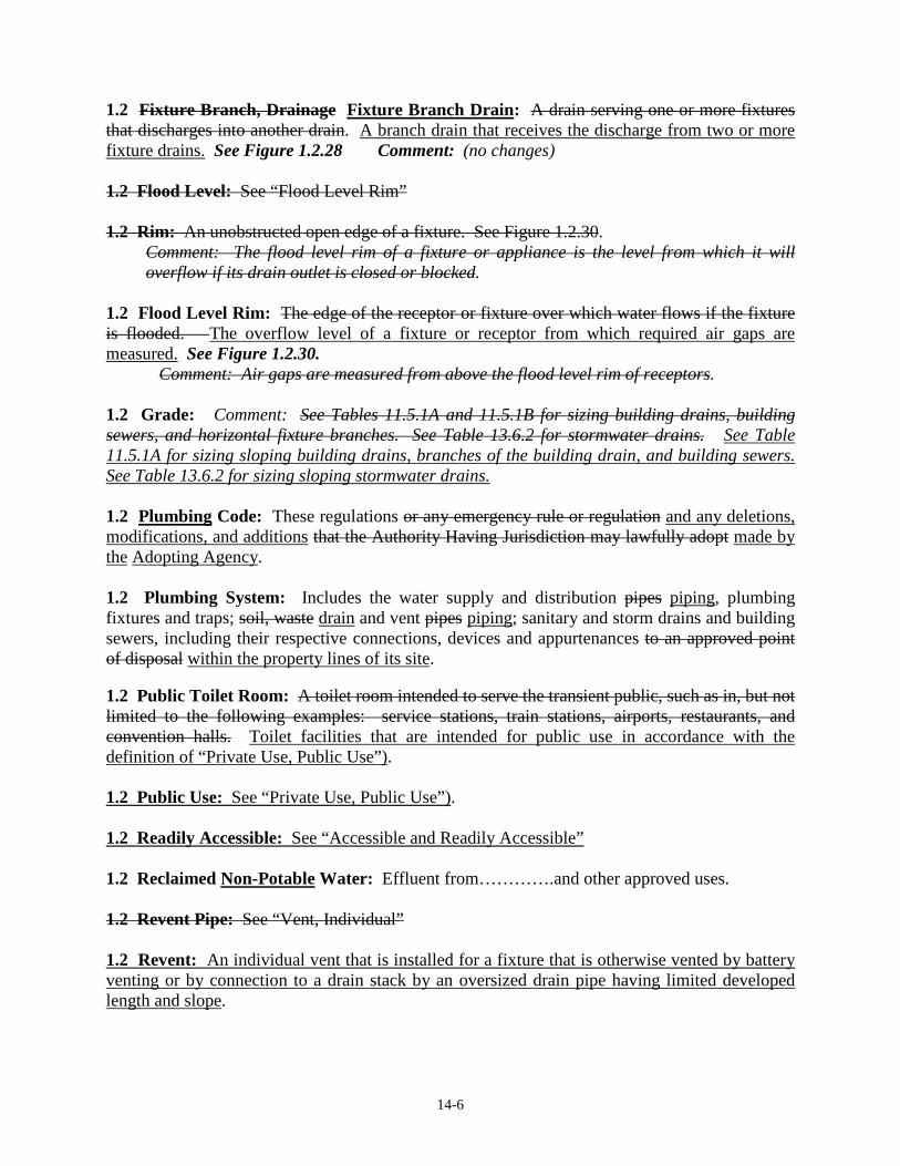
14-6
1.2 Fixture Branch, Drainage Fixture Branch Drain: A drain serving one or more fixtures that discharges into another drain. A branch drain that receives the discharge from two or more fixture drains. See Figure 1.2.28 Comment: (no changes) 1.2 Flood Level: See “Flood Level Rim” 1.2 Rim: An unobstructed open edge of a fixture. See Figure 1.2.30. Comment: The flood level rim of a fixture or appliance is the level from which it will
overflow if its drain outlet is closed or blocked. 1.2 Flood Level Rim: The edge of the receptor or fixture over which water flows if the fixture is flooded. The overflow level of a fixture or receptor from which required air gaps are measured. See Figure 1.2.30. Comment: Air gaps are measured from above the flood level rim of receptors. 1.2 Grade: Comment: See Tables 11.5.1A and 11.5.1B for sizing building drains, building sewers, and horizontal fixture branches. See Table 13.6.2 for stormwater drains. See Table 11.5.1A for sizing sloping building drains, branches of the building drain, and building sewers. See Table 13.6.2 for sizing sloping stormwater drains. 1.2 Plumbing Code: These regulations or any emergency rule or regulation and any deletions, modifications, and additions that the Authority Having Jurisdiction may lawfully adopt made by the Adopting Agency. 1.2 Plumbing System: Includes the water supply and distribution pipes piping, plumbing fixtures and traps; soil, waste drain and vent pipes piping; sanitary and storm drains and building sewers, including their respective connections, devices and appurtenances to an approved point of disposal within the property lines of its site. 1.2 Public Toilet Room: A toilet room intended to serve the transient public, such as in, but not limited to the following examples: service stations, train stations, airports, restaurants, and convention halls. Toilet facilities that are intended for public use in accordance with the definition of “Private Use, Public Use”). 1.2 Public Use: See “Private Use, Public Use”). 1.2 Readily Accessible: See “Accessible and Readily Accessible” 1.2 Reclaimed Non-Potable Water: Effluent from………….and other approved uses. 1.2 Revent Pipe: See “Vent, Individual” 1.2 Revent: An individual vent that is installed for a fixture that is otherwise vented by battery venting or by connection to a drain stack by an oversized drain pipe having limited developed length and slope.

14-6
1.2 Reventing: The installation of individual vents for fixtures that are also vented by other means. Comment: Reventing is not required in Sections 12.12.2, 12.12.3, and 12.12.4. 1.2 Riser, Water Supply: A water supply pipe that extends vertically one full story or more with branches to convey water to branches or to a group of fixtures plumbing fixtures and water-supplied equipment. See Figure 1.2.49 Comment: The term “riser” refers to vertical water supply piping serving one or more fixtures in buildings having one or more story heights. 1.2 Roof Drain: A drain installed to receive rainwater collecting on the surface of a roof and to discharge it into a conductor or leader. or a conductor. See Figure 1.2.50 1.2 Roughing-in, Rough Plumbing: The installation of all parts of the plumbing system that can be completed prior to the installation of fixtures. This includes drainage, water supply, and vent piping, and the necessary fixture supports, or any fixtures that are built into the structure. 1.2 Sanitary Sewer: A sewer that carries sewage and excludes storm, surface or ground water. A system of public or private drain piping or conduits that convey sewage from one or more properties to a point of treatment or disposal. 1.2 Stack Venting: A method of venting a fixture or fixtures bathroom group through a soil or waste stack a stack vent or the vent for a sub-stack. See Figure Figures 1.2.57, 12.11.1-A&B, 12.11.2-A&B, and Section 12.11 1.2 Sub-Stack: A vertical branch drain from a drain stack that serves a stack group of fixtures on the same floor level. See Figure 12.11.2-A 1.2 Tub/Shower: A bathtub, shower, bath/shower combination, or whirlpool bath. 1.2 Vent, Back: An individual vent or continuous vent. 1.2 Vent, Branch: A vent connecting one two or more individual fixture vents with a vent stack or stack vent to a vent riser, vent stack, stack vent, or outdoor vent terminal. See Figure 1.2.70 1.2 Vent, Circuit: A vent that connects to a horizontal drainage branch and vents from two to eight traps or trapped fixtures connected in a battery The vent for a group of battery-vented fixtures that is connected to their horizontal drain branch between the first two upstream fixtures and extends to a vent stack or other vertical vent. See Figure 1.2.71 Comment: Circuit vents connect to vent stacks. Loop vents connect to stack vents. 1.2 Vent, Loop: A circuit vent that loops back to connect with a and connects to its stack vent instead of a vent stack vent riser or vent stack. See Figure 12.13.1 1.2 Vent Riser: A vertical vent pipe with connections from fixture vents, branch vents, and circuit vents on different floor levels that connects to a stack vent, vent stack, or outdoor vent terminal. Not a vent stack.

14-6
1.2 Vent, Side: A vent connecting to a horizontal or vertical drain pipe through a fitting at an angle not greater than 45º to the vertical not more than 45º from vertical. See Figure 1.2.76 1.2 Vent Stack: A vertical vent pipe that extends through one or more stories and that is intended to provide circulation of air to and from the drainage system that is connected to the base of a drain stack having five or more branch intervals. It extends up and connects to the stack vent or an outdoor vent terminal to relief the pressure at the base of the drain stack. It is sized according to Section 12.16.4. See Figures 1.2.78 and 12.3.1 1.2 Vent, Yoke: A vent pipe connecting upward from a soil or waste up to ten branch intervals of a drain stack to a to its vent stack for the purpose of equalizing the pressures in the two stacks to relieve the pressure in the drain stack. See Figure 1.2.78 and Section 12.3.2 Comment: (no changes) 1.2 Water Service Pipe Piping: A pipe Piping from a water main(,) or other source of potable water supply(,) to the water distribution system of within the building served. See Figure 1.2.82 and Section 10.6. (delete 2 commas) 1.2 WSFU: See “Fixture Unit (Water Supply – WSFU)” Basis/Reason for Change: To coordinate definitions in Section 1.2 with their usage in the Code. Vote: ___ Accept ___ Accept as Amended
___ Accept in Part ___ Accept in Principle ___ Accept in Part and Principle
___ Defeated ___Failed Lack of Second ___ Tabled ___ Withdrawn ___ Other ______________________________________________________________________________

14-7
National Standard Plumbing Code 2015 Proposed Code Change Form
14 - 07
Contact Information: Person Submitting Change NSPC Committee Date 04-30-2014 . Mailing Address 180 S. Washington Street, P.O. Box 6808 . City/State/Zip Falls Church, VA 22046 . Phone 1-800-533-7694 Fax 1-703-237-7442 E-mail [email protected] Check All That Apply: ___ Amend section with this editorial change __X_ Change subsection to read as follows ____ Delete subsection and substitute as follows ____ Add new subsection to read as follows ____ Delete subsection without substitution Code Section: 1.2 DEFINITION OF TERMS 1.2 Reduced Pressure Backflow Preventer Assembly: See Reduced Pressure Zone Backflow Preventer Assembly. 1.2 Reduced Pressure Principle Assembly: A reduced pressure zone backflow preventer assembly. 1.2 Reduced Pressure Zone Principle Backflow Preventer Assembly: A backflow prevention device assembly with shutoff valves consisting of two independently acting check valves, internally force loaded to a normally closed position and separated by an intermediate chamber (or zone), in which there is an automatic relief means of venting to atmosphere, internally loaded to a normally an open position, and with means for testing for tightness of the checks and opening of the relief means. See Figure 1.2.48
Comment: Reduced pressure principle backflow preventer assemblies preventers provide the highest level of protection against backpressure back pressure and back siphonage. backflow. The shutoff valves on these assemblies are resiliently seated to assure tight close-off for testing and repairing. Provisions must be made to drain any discharge from the relief vent outlet, which may occur due to normal variations in system pressure.
Figure 1.2.48 A REDUCED PRESSURE BACKFLOW PREVENTER ASSEMBLY
Basis/Reason for Change: To clarify the definition of reduced pressure backflow preventers. Vote: ___ Accept ___ Accept as Amended
___ Accept in Part ___ Accept in Principle ___ Accept in Part and Principle
___ Defeated ___Failed Lack of Second ___ Tabled ___ Withdrawn ___ Other ______________________________________________________________________________

14-8
National Standard Plumbing Code 2015 Proposed Code Change Form
14 - 08
Contact Information: Person Submitting Change NSPC Committee Date 4-30-2014 . Mailing Address 180 S. Washington Street, P.O. Box 6808 . City/State/Zip Falls Church, VA 22046 . Phone 1-800-533-7694 Fax 1-703-237-7442 E-mail [email protected] Check All That Apply: ___ Amend section with this editorial change __X_ Change subsection to read as follows ____ Delete subsection and substitute as follows ____ Add new subsection to read as follows ____ Delete subsection without substitution Code Section: 1.2 DEFINITION OF TERMS 1.2 Sewage: Liquid containing human waste (including fecal matter) and/or animal, vegetable, or chemical waste matter in suspension or solution. Liquid discharge into the plumbing drainage system from a fixture, appliance, or other connection that contains urine and/or fecal matter. 1.2 Soil Pipe or Soil Stack: Pipes that convey sewage containing fecal matter to the building drain or building sewer. A drain pipe that conveys sewage. 1.2 Waste: Any remaining liquid, or liquid-borne material or residue intended to be discharged to the drainage system after any activity or process, but not including any such materials that contain animal or human fecal matter. Liquid discharge into the plumbing drainage system from a fixture, appliance, or other connection that does not contain urine or fecal matter. Basis/Reason for Change: To clarify the definitions of “sewage”, “soil”, and “waste” with regard to urine. Vote: ___ Accept ___ Accept as Amended
___ Accept in Part ___ Accept in Principle ___ Accept in Part and Principle
___ Defeated ___Failed Lack of Second ___ Tabled ___ Withdrawn ___ Other ______________________________________________________________________________

14-9
National Standard Plumbing Code 2015 Proposed Code Change Form
14 - 09
Contact Information: Person Submitting Change NSPC Committee Date 03-22-2014 . Mailing Address 180 S. Washington Street, P.O. Box 6808 . City/State/Zip Falls Church, VA 22046 . Phone 1-800-533-7694 Fax 1-703-237-7442 E-mail [email protected] Check All That Apply: ___ Amend section with this editorial change ____ Change subsection to read as follows ____ Delete subsection and substitute as follows ____ Add new subsection to read as follows __X_ Delete subsection without substitution Code Section: 1.2 DEFINITION OF TERMS Sewage Pump or Pump-Type Ejector: A non-clog or grinder-type sewage pump or ejector. Sewage pumps and pump-type ejectors are either the submersible or vertical type. See Figure 1.2.54 and Section 11.7
Comment: Figure 1.2.54 shows a pedestal-type sewage pump. Sewage pumps can also be submersible pumps or dry-pit centrifugal pumps.
Delete Figure 1.2.54 A PEDESTAL TYPE SEWAGE PUMP Basis/Reason for Change: The definition and Figure do not define or illustrate the numerous different types of sewage pumps and ejectors and their applications. There are many other types of level controls besides the top mount float type in Figure 1.2.54. The definition and Figure do not clarify requirements of the Code. Vote: ___ Accept ___ Accept as Amended
___ Accept in Part ___ Accept in Principle ___ Accept in Part and Principle
___ Defeated ___Failed Lack of Second ___ Tabled ___ Withdrawn ___ Other ______________________________________________________________________________

14-10
National Standard Plumbing Code 2015 Proposed Code Change Form
14 - 10
Contact Information: Person Submitting Change NSPC Committee Date 03-21-2014 . Mailing Address 180 S. Washington Street, P.O. Box 6808 . City/State/Zip Falls Church, VA 22046 . Phone 1-800-533-7694 Fax 1-703-237-7442 E-mail [email protected] Check All That Apply: ___ Amend section with this editorial change __X_ Change subsection to read as follows ____ Delete subsection and substitute as follows ____ Add new subsection to read as follows ____ Delete subsection without substitution Code Section: 1.2 DEFINITION OF TERMS Stack: A general term for any vertical line including offsets or soil, waste, vent or inside conductor piping. This does not include vertical fixture and vent branches that do not extend through the roof or pass through not more than two stories before being reconnected to the vent stack or stack vent. See Figure 1.2.56, Section 11.5.2, and Table 11.5.1B
Comment: Stacks include soil stacks, waste stacks, vent stacks, and stack vents. See separate definitions.
Stack: Vertical drain piping and vent piping, with or without offsets, that serves multiple fixtures on two or more story heights. Revise Figure 1.2.56 A Stack Vent Change “Soil Stack” to “Drain Stack” Delete “Vent Stack” Basis/Reason for Change: To clarify the definition of “stack”as used in the code. Vote: ___ Accept ___ Accept as Amended
___ Accept in Part ___ Accept in Principle ___ Accept in Part and Principle
___ Defeated ___Failed Lack of Second ___ Tabled ___ Withdrawn ___ Other ______________________________________________________________________________

14-11
National Standard Plumbing Code 2015 Proposed Code Change Form
14 - 11
Contact Information: Person Submitting Change NSPC Committee Date 04-30-2014 . Mailing Address 180 S. Washington Street, P.O. Box 6808 . City/State/Zip Falls Church, VA 22046 . Phone 1-800-533-7694 Fax 1-703-237-7442 E-mail [email protected] Check All That Apply: ___ Amend section with this editorial change __X_ Change subsection to read as follows ____ Delete subsection and substitute as follows ____ Add new subsection to read as follows ____ Delete subsection without substitution Code Section: 1.2 Storm Drains 1.2 Storm Water: Rainwater, surface water, and ground water. 1.2 Storm Drain: See ”Building Drain, Storm” A drain that conveys only storm water. 1.2 Building Drain, Storm: A building drain that conveys only storm water or other drainage, but no sewage from the building to the building storm sewer. See Figure 1.2.16 1.2 Storm Sewer: A sewer used for conveying An underground drain that conveys only rainwater, surface water, and ground water. condensate, cooling water, or similar liquid wastes. 1.2 Building Sewer, Storm: A building sewer that conveys only storm water or other drainage, but no sewage from the building storm drain to a public storm sewer or other point of disposal. It does not extend beyond any property lines if discharging to an off-site public sewer or off-site point of disposal. See Figure 1.2.16 Basis/Reason for Change: To coordinate the definitions of the different storm drain piping. Vote: ___ Accept ___ Accept as Amended
___ Accept in Part ___ Accept in Principle ___ Accept in Part and Principle
___ Defeated ___Failed Lack of Second ___ Tabled ___ Withdrawn ___ Other ______________________________________________________________________________

National Standard Plumbing Code 2015 Proposed Code Change Form Deadline April 30, 2014
14 - 12
14-12
Contact Information: Person Submitting Change 2 Donald M. Jones Date 3 April 23, 2014 Jurisdiction/Company/ Mailing Address 202 W. Summit St. City/State/Zip Vineland, NJ 08360 Phone (609)517-1473 Fax __________________ E-mail [email protected] IMPORTANT: Please review the attached instruction sheet regarding proposed code changes. Check All That Apply: _____ Amend section with this editorial change X Change subsection to read as follows _____ Delete subsection and substitute as follows _____ Add new subsection to read as follows _____ Delete subsection without substitution Code Section: NSPC 2.3.1 THE FOLLOWING AMENDMENT IS SUBMITTED: NSPC 2.3.1
a. Changes in direction of drainage piping shall be made with long radius drainage fittings except where short radius fittings are permitted in Table 2.3.1. Refer to Table 2.3.1 for permissible drainage fittings for changes of directions.
b. Short radius drainage fittings are those having radius or centerline dimensions that are approximately equal to or less than their nominal pipe size. The radius or centerline dimensions of long radius drainage fittings are greater than their nominal pipe size.
c. Long radius drainage fittings shall not be used to connect fixture trap arms to vertical drain and vent piping. Connections to fixture vents shall be above the top weir of the fixture trap.
EXCEPTIONS:
(1) Double wyes with 1/8 bends or 45-degree elbows that drain two lavatories into a common drain with a common vent shall be permitted.
(2) Double fixture fittings that drain two fixtures into a common drain with a common vent shall be permitted

14-12
Basis/Reason for Change: Double fixture fittings are long radius fittings that possess a branch end-to-center dimension greater than a long sweep 90° elbow. They have an even greater throat dimension, which yields an enlarged chamber that limits cross-flow or throw-over, so they are ideal for both draining and rodding. The vent connection of these fittings is far less intrusive than that of a double combination wye and 1/8 bend. Double fixture fittings are unique in that their venting capability is similar to double sanitary tees and their drainage pattern resembles double wyes with 1/8 bends. Double wyes with 1/8 bends have been installed in this manner for years without incident, so an “Exception” was added to the 2012 NSPC. Similarly, double fixture fittings have been used for years without incident. These fittings are worthy of a greater exception than double combination wye and 1/8 bends because of their design and history of performance in the field. . Vote: ___ Accept ___ Accept as Amended
___ Accept in Part ___ Accept in Principle ___ Accept in Part and Principle
___ Defeated ___Failed Lack of Second ___ Tabled ___ Withdrawn ___ Other ____________________________________________________________________________________

National Standard Plumbing Code 2015 Proposed Code Change Form Deadline April 30, 2014
14 - 13
14-13
Contact Information: Person Submitting Change 2 _____ Ron George __________________ Date 3 _4-21-14 ______ Jurisdiction/Company/ Mailing Address ___Plumb-Tech Design and Consulting Services LLC. P.O. Box 47 _________ City/State/Zip ____ Newport, MI 48166______________________________________ Phone ___734-322-0225_ Fax _734-322-2949 E-mail __ [email protected] ______ IMPORTANT: Please review the attached instruction sheet regarding proposed code changes. Check All That Apply: _____ Amend section with this editorial change _____ Change subsection to read as follows _____ Delete subsection and substitute as follows _____ Add new subsection to read as follows _____ Delete subsection without substitution Code Section: __ Chapter 2 Section 2.4.3 2.4.3 Obstruction to Flow a. No fitting, connection, device or method of installation that obstructs or retards the flow of water, wastes, sewage, or air in the drainage or venting systems in an amount greater than the normal frictional resistance flow, shall be used unless it is indicated as acceptable in this Code. b. 4x3 closet bends and 4x3 closet flanges shall not be considered as obstructions to flow. c. Devices that comply with ASME A112.18.8-2009 “ In -Line Sanitary Waste Valves for Plumbing Drainage Systems” shall not b e considered as obstructions to flow. Basis/Reason for Change: ASME recently developed an industry standard for “In-Line Sanitary Waste Valves for Plumbing Drainage Systems” (ASME A122.18.8-2009). These devices do not obstruct or retard the flow of water, wastes, sewage, or air in the drainage or venting systems in an amount greater than the normal frictional resistance flow. Vote: ___ Accept ___ Accept as Amended
___ Accept in Part ___ Accept in Principle ___ Accept in Part and Principle
___ Defeated ___Failed Lack of Second ___ Tabled ___ Withdrawn ___ Other ____________________________________________________________________________________

14-14
National Standard Plumbing Code 2015 Proposed Code Change Form
14 - 14
Contact Information: Person Submitting Change NSPC Committee Date 02-11-2014 . Mailing Address 180 S. Washington Street, P.O. Box 6808 . City/State/Zip Falls Church, VA 22046 . Phone 1-800-533-7694 Fax 1-703-237-7442 E-mail [email protected] Check All That Apply: ___ Amend section with this editorial change ____ Change subsection to read as follows ____ Delete subsection and substitute as follows _X_ Add new subsection to read as follows ____ Delete subsection without substitution Code Section: 2.4.5 Accessible Joints Plastic tube and tubular fixture traps and waste fittings complying with ASTM F409 with slip joints shall be accessible for adjustment, maintenance, and replacement. Basis/Reason for Change: To add requirements for the use of ASTM F409 accessible, replaceable fixture drain fittings. Vote: ___ Accept ___ Accept as Amended
___ Accept in Part ___ Accept in Principle ___ Accept in Part and Principle
___ Defeated ___Failed Lack of Second ___ Tabled ___ Withdrawn ___ Other ______________________________________________________________________________

14-15
National Standard Plumbing Code 2015 Proposed Code Change Form
14 - 15
Contact Information: Person Submitting Change NSPC Committee Date 04-30-2014 Mailing Address 180 S. Washington Street, P.O. Box 6808 . City/State/Zip Falls Church, VA 22046 . Phone 1-800-533-7694 Fax 1-703-237-7442 E-mail [email protected] Check All That Apply: ___ Amend section with this editorial change __X_ Change subsection to read as follows ____ Delete subsection and substitute as follows ____ Add new subsection to read as follows ____ Delete subsection without substitution Code Section: 2.6 TRENCHING, BEDDING, TUNNELING AND BACKFILLING 2.6.3 Initial Backfill After installation of the side-fill, the trench shall be backfilled to a level not less than 2 feet above the top of the pipe. Backfill material shall be sand, gravel, or loose soil that is free of rocks and debris. Maximum particle size shall be 1-1/2 inches. Backfill shall be placed in not more than 6-inch layers, each tamped and compacted. Heavy equipment shall not be used for the initial backfill. a. Backfill material shall be sand, gravel, or loose soil that is free of rocks and debris. Maximum particle size shall be 1-1/2 inches. b. The side-fill adjacent to the pipe shall be backfilled, tamped, and compacted to the top of the pipe. c. After the side-fill is backfilled, the trench shall be backfilled in not more than 6-inch layers, each tamped and compacted, to a level not less than 2 feet above the top of the pipe. d. Heavy equipment shall not be used for the initial backfill. Basis/Reason for Change: To add the requirement that the side-fill be backfilled to the top of the pipe. Vote: ___ Accept ___ Accept as Amended
___ Accept in Part ___ Accept in Principle ___ Accept in Part and Principle
___ Defeated ___Failed Lack of Second ___ Tabled ___ Withdrawn ___ Other ______________________________________________________________________________

14-16
National Standard Plumbing Code 2015 Proposed Code Change Form
14 - 16
Contact Information: Person Submitting Change NSPC Committee Date 02-11-2014 . Mailing Address 180 S. Washington Street, P.O. Box 6808 . City/State/Zip Falls Church, VA 22046 . Phone 1-800-533-7694 Fax 1-703-237-7442 E-mail [email protected] Check All That Apply: ___ Amend section with this editorial change __X_ Change subsection to read as follows ____ Delete subsection and substitute as follows ____ Add new subsection to read as follows ____ Delete subsection without substitution Code Section: 2.9 PROTECTION OF PIPES 2.9.1 From Breakage 2.9.2 From Corrosion 2.9.3 Cutting or Notching From Weakened Structure 2.9.4 Penetration From Nails, Screws, and Other Fasteners a. Plastic and copper piping run though framing members (wood or metal) to within one inch of the edge of the framing shall be protected by steel nail plates not less than 18 thinner than 16 gauge. Where such piping penetrates top plates or sole plates of the framing, the nail plate shall extend at least two inches below top plates and two inches above sole plates. b. Where finished walls or ceilings are attached to the framing using power-operated nail guns or screw guns, the protection plates shall be case hardened steel. b. c. Where plastic and copper piping runs through metal framing members, it shall be protected from abrasion caused by expansion and contraction of the piping or movement of the framing. Basis/Reason for Change: To clarify the requirements for protection of pipes. To provide additional protection from nail guns and screw guns. Vote: ___ Accept ___ Accept as Amended
___ Accept in Part ___ Accept in Principle ___ Accept in Part and Principle
___ Defeated ___Failed Lack of Second ___ Tabled ___ Withdrawn ___ Other ______________________________________________________________________________

14-17
National Standard Plumbing Code 2015 Proposed Code Change Form
14 - 17
Contact Information: Person Submitting Change NSPC Committee Date 04-30-2014 . Mailing Address 180 S. Washington Street, P.O. Box 6808 . City/State/Zip Falls Church, VA 22046 . Phone 1-800-533-7694 Fax 1-703-237-7442 E-mail [email protected] Check All That Apply: ___ Amend section with this editorial change __X_ Change subsection to read as follows ____ Delete subsection and substitute as follows ____ Add new subsection to read as follows ____ Delete subsection without substitution Code Section: 2.23 DEAD ENDS 2.23.1 Drain Piping a. In the installation or removal of any part of a drainage or vent system, dead ends, as defined in Section 1.2, shall be avoided. EXCEPTION: Where necessary to extend a cleanout so as to be accessible. a. In the installation of drain piping, dead ends shall not be permitted.
EXCEPTION: Piping to make cleanouts accessible, if it is self-draining. See Figure 5.4.5 - B
b. Rough-ins for future fixtures shall not be considered dead ends if the piping is accessible, self-draining, and can be cleaned of any blockages when the future fixtures are installed. c. If an existing fixture, appliance, or equipment is removed, any open ends in the drain piping shall be capped or plugged watertight. Dead ends that are not self-draining shall not be permitted. 2.23.2 Vent Piping In the installation, removal, or disconnecting of any vent piping, any open ends shall be capped or plugged watertight. Dead ends that are not self-draining shall not be permitted.
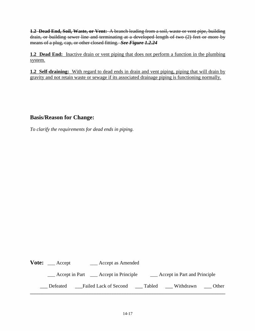
14-17
1.2 Dead End, Soil, Waste, or Vent: A branch leading from a soil, waste or vent pipe, building drain, or building sewer line and terminating at a developed length of two (2) feet or more by means of a plug, cap, or other closed fitting. See Figure 1.2.24 1.2 Dead End: Inactive drain or vent piping that does not perform a function in the plumbing system. 1.2 Self-draining: With regard to dead ends in drain and vent piping, piping that will drain by gravity and not retain waste or sewage if its associated drainage piping is functioning normally. Basis/Reason for Change: To clarify the requirements for dead ends in piping. Vote: ___ Accept ___ Accept as Amended
___ Accept in Part ___ Accept in Principle ___ Accept in Part and Principle
___ Defeated ___Failed Lack of Second ___ Tabled ___ Withdrawn ___ Other ______________________________________________________________________________

14-18
National Standard Plumbing Code 2015 Proposed Code Change Form
14 - 18
Contact Information: Person Submitting Change NSPC Committee Date 03-27-2014 . Mailing Address 180 S. Washington Street, P.O. Box 6808 . City/State/Zip Falls Church, VA 22046 . Phone 1-800-533-7694 Fax 1-703-237-7442 E-mail [email protected] Check All That Apply: ___ Amend section with this editorial change __X_ Change subsection to read as follows ____ Delete subsection and substitute as follows ____ Add new subsection to read as follows ____ Delete subsection without substitution Code Section: 2.25 FOOD HANDLING ESTABLISHMENTS, ETC 2.25.5 Sanitary Floor Sinks a. Where sanitary floor sinks serve as waste receptors in food handing areas, they shall not be located where subject to foot traffic or other loads on their grates, if provided. b. Sanitary floor sinks shall comply with ASME A112.6.7 and shall be of the sanitary design with smooth, corrosion-resistant surfaces that can be readily cleaned. They shall include a dome strainer over the outlet opening to prevent clogging the drain or a sediment bucket to collect solids. Basis/Reason for Change: To reference the standard for sanitary floor sinks. Vote: ___ Accept ___ Accept as Amended
___ Accept in Part ___ Accept in Principle ___ Accept in Part and Principle
___ Defeated ___Failed Lack of Second ___ Tabled ___ Withdrawn ___ Other ______________________________________________________________________________

14-19
National Standard Plumbing Code 2015 Proposed Code Change Form
14 - 19
Contact Information: Person Submitting Change NSPC Committee Date 3-23-2014 . Mailing Address 180 S. Washington Street, P.O. Box 6808 . City/State/Zip Falls Church, VA 22046 . Phone 1-800-533-7694 Fax 1-703-237-7442 E-mail [email protected] Check All That Apply: ____ Amend section with this editorial change __X_ Change subsection to read as follows ____ Delete subsection and substitute as follows ____ Add new subsection to read as follows ____ Delete subsection without substitution Code Section: 2.26 ELEVATOR SUMP PITS 2.26 ELEVATOR SUMP PITS Provisions for draining elevator sump pits shall be in accordance with the requirements of the Adopting Agency. 2.26 REQUIREMENTS FOR ELEVATORS 2.26.1 General a. The plumbing requirements for elevator shafts, pits, and equipment rooms shall be in accordance with the applicable elevator code. b. Piping shall not be installed in elevator machine rooms that is prohibited by the applicable elevator code. c. Foundation drains and other sources of ground water shall not be connected to elevator pits. d. Where elevators have Phase II firefighter override, drainage shall be provided for their elevator pit.

14-19
2.26.2 Where Elevator Pit Drainage is Provided a. Drainage from elevator pit drains or pumps shall discharge to the sanitary drainage system or to outdoors. Such drainage shall not be connected to storm drain piping. b. Where the drainage discharge is outdoors, the location shall be approved by the Authority Having Jurisdiction and be marked “ELEVATOR PIT DISCHARGE”. c. An indoor discharge from elevator pit drains or pumps shall extend from the pit to an indirect waste receptor or be connected to gravity drain piping indirectly through an air gap or air break. The point of discharge shall be marked “ELEVATOR PIT DISCHARGE”.
d. The controls for sump pumps serving hydraulic elevators shall include automatic oil sensing with pump cutoff or there shall be oil separation for pump operation.
e. Sump pits for drains or pumps shall have a removable or operable grate-type cover that is
secured and level with the elevator pit floor. f. The discharge piping from elevator sump pumps shall include a check valve and a
manual quarter-turn shutoff valve with visual indication of its full open and full closed positions from within the elevator pit. g. Where elevators have Phase II firefighter override, the design flow capacity of the required drains or pumps shall be not less than 3000 gph (50 gpm) per elevator. Pumps for hydraulic elevators shall have oil separation for pump operation. Basis/Reason for Change: To indicate the requirements for the drainage of elevator pits, which are subject to the requirements of the local elevator code. Elevator codes are typically based on ASME A17.1 Safety Code for Elevators and Escalators. Vote: ___ Accept ___ Accept as Amended
___ Accept in Part ___ Accept in Principle ___ Accept in Part and Principle
___ Defeated ___Failed Lack of Second ___ Tabled ___ Withdrawn ___ Other ______________________________________________________________________________

14-20
National Standard Plumbing Code 2015 Proposed Code Change Form
14 - 20
Contact Information: Person Submitting Change NSPC Committee Date 03-29-2014 . Mailing Address 180 S. Washington Street, P.O. Box 6808 . City/State/Zip Falls Church, VA 22046 . Phone 1-800-533-7694 Fax 1-703-237-7442 E-mail [email protected] Check All That Apply: ___ Amend section with this editorial change ____ Change subsection to read as follows ____ Delete subsection and substitute as follows __X_ Add new subsection to read as follows ____ Delete subsection without substitution Code Section: Chapter 2 General Regulations 2.30 SWIMMING POOLS, WADING POOLS, SPAS, AND HOT TUBS a. The water supply shall be protected from backflow by a fixed air gap above the overflow level of the pool, spa, or hot tub, or by an approved backflow protection device. Where the water supply connection is below the overflow level, an ASSE 1013 reduced pressure principle backflow preventer shall be provided. b. The drainage from swimming pools and wading pools shall be indirect through an air gap in accordance with Section 9.1.11. Basis/Reason for Change: To add the plumbing requirements for swimming pools, wading pools, spas, and hot tubs. Vote: ___ Accept ___ Accept as Amended
___ Accept in Part ___ Accept in Principle ___ Accept in Part and Principle
___ Defeated ___Failed Lack of Second ___ Tabled ___ Withdrawn ___ Other ______________________________________________________________________________

14-21
National Standard Plumbing Code 2015 Proposed Code Change Form
14 - 21
Contact Information: Person Submitting Change NSPC Committee Date 04-09-2014 . Mailing Address 180 S. Washington Street, P.O. Box 6808 . City/State/Zip Falls Church, VA 22046 . Phone 1-800-533-7694 Fax 1-703-237-7442 E-mail [email protected] Check All That Apply: ___ Amend section with this editorial change ____ Change subsection to read as follows _X_ Delete subsection and substitute as follows ____ Add new subsection to read as follows ____ Delete subsection without substitution Code Section: Table 3.1.3 Replace existing Table 3.1.3 - Parts I thru XI with attached Table 3.1.3 - Parts I thru XI. Table 3.1.3 STANDARDS FOR APPROVED PLUMBING MATERIALS, EQUIPMENT, AND PRACTICES Table 3.1.3 APPROVED MATERIALS Part I Ferrous Pipe and Fittings (2/23/14 - 1 page) Part II Non-Ferrous Pipe and Fittings (2/23/14 - 1 page) Part III Non-Metallic Pipe and Fittings (2/23/14 - 2 pages) Part IV Pipe Joints, Joining Materials, Couplings, Gaskets (4/09/14 - 1 page) Part V Plumbing Fixtures (2/23/14 - 1 page) Part VI Plumbing Fixture Trim and Accessories (2/23/14 - 1 page) Part VII Plumbing Appliances (2/23/14 - 1 page) Part VIII Valves and Appurtenances (2/23/14 - 1 page) Part IX Backflow Prevention (2/23/14 - 1 page) Part X Miscellaneous Materials (2/23/14 - 1 page) Part XI Installation Procedures and Practices (2/23/14 - 1 page) Basis/Reason for Change: To update Table 3.1.3 for approved materials. The materials are essentially the same as in existing Table 3.1.3. The changes from the 2013 Supplement to the 2012 NSPC are included. The designations of the standards for some of the basic products have changed. Some are now combined with CSA standards. The materials in the different parts of the Table are now listed in alphabetical order for convenience. The referenced standards for the materials with their complete titles and dates are now listed in new Table 19.1, along with the other standards that are referenced within the text of the Code. The listings in Table 19.1 include where the references to the standards are located in the Code.

14-21
Table 3.1.3 - Part I FERROUS PIPE AND FITTINGS 1 Cast iron threaded drainage fittings ASME B16.12 2 Cement mortar lining for ductile iron pipe and fittings AWWA C104/A21.4 3 Ductile iron compact water service fittings AWWA C153/A21.53 4 Ductile iron culvert pipe ASTM A716 5 Ductile iron gravity sewer pipe ASTM A746
6 Ductile iron pressure pipe ASTM A377 AWWA C151/A21.51
7 Ductile iron and gray iron fittings AWWA C110/A21.10 8 Ferrous pipe flanges and flanged fittings ASME B16.5 9 Gray iron threaded fittings, class 125 & 250 ASME B16.4 10 Hub & spigot cast iron soil pipe and fittings ASTM A74
11 Hubless cast iron soil pipe and fittings CISPI 301 ASTM A888
12 Malleable iron threaded fittings, class 150 & 300 ASME B16.3 13 Stainless steel DWV pipe and fittings, 304 & 316L ASME A112.3.1 14 Steel pipe, galvanized, welded, seamless ASTM A53 15 Threaded ferrous pipe plugs, bushings, and locknuts ASME B16.14
Table 3.1.3 - Part II NON-FERROUS PIPE AND FITTINGS 1 Cast bronze threaded fittings, class 125 & 250 ASME B16.15 2 Cast copper fittings for flared copper tube ASME B16.26 3 Cast copper pipe flanges and flanged fittings ASME B16.24 4 Cast copper solder joint drainage fittings ASME B16.23 5 Cast copper solder joint pressure fittings ASME B16.18 6 Copper drainage tube (DWV) ASTM B306 7 Copper pipe, threadless ASTM B302 8 Copper water tube (K, L, M) ASTM B88 9 Press-connect pressure fittings, copper and copper alloy ASME B16.51 10 Push-fit fittings for copper water tube ASSE 1061 11 Red brass pipe, seamless ASTM B43 12 Wrought copper braze joint pressure fittings ASME B16.50 13 Wrought copper solder joint drainage fittings ASME B16.29 14 Wrought copper solder joint pressure fittings ASME B16.22

14-21
Table 3.1.3 - Part III NON-METALLIC PIPE AND FITTINGS 1 ABS plastic DWV pipe with cellular core, schedule 40 ASTM F628 2 ABS plastic DWV pipe and fittings CSA B181.1 3 ABS plastic DWV pipe and fittings, schedule 40 ASTM D2661 4 ABS plastic sewer pipe and fittings ASTM D2751 5 ABS/PVC plastic composite sewer pipe ASTM D2680 6 Clay drain tile ASTM C4 7 CPVC plastic DWV pipe and fittings CSA B181.2 8 CPVC plastic pipe, schedule 40 & 80 ASTM F441 9 CPVC plastic pipe, SDR-PR ASTM F442 10 CPVC plastic pipe and fittings, chemical waste drainage ASTM F2618 11 CPVC plastic pipe fittings, socket-type, schedule 40 ASTM F438 12 CPVC plastic pipe fittings, socket-type, schedule 80 ASTM F439 13 CPVC plastic pipe fittings, threaded, schedule 80 ASTM F437 14 CPVC plastic pipe, tubing, and fittings for HW/CW distribution (copper tube size) ASTM D2846 15 CPVC plastic pipe, tubing, and fittings for HW/CW distribution (schedule 40 & 80) CSA B137.6 16 CPVC-AL-CPVC plastic tubing, (copper tube size) ASTM F2855 17 Cold expansion fittings with metal compression sleeves for PEX pipe ASTM F2080 18 Cold expansion fittings with PEX reinforcing rings for PEX tubing ASTM F1960 19 Concrete culvert, storm drain, and sewer pipe, non-reinforced ASTM C14 20 Concrete culvert, storm drain, and sewer pipe, reinforced ASTM C76 21 Concrete drain tile ASTM C412 22 Concrete perforated pipe ASTM C444 23 Corrugated PE plastic tubing and fittings ASTM F405 24 Fiberglass (GFR) pipe fittings, non-pressure ASTM D3840 25 Fiberglass (GFR) pressure pipe ASTM D3517 26 Fiberglass (GFR) sewer pipe ASTM D3262 27 Fiberglass pressure pipe AWWA C950 28 Flexible pre-insulated piping ASTM F2165 29 Insert fittings for PEX tubing, mechanical cold expansion, with compression sleeve ASTM F1865 30 Mechanical cold flare compression fittings with disc spring for PEX tubing ASTM F1961 31 Metal insert fittings for PE-AL-PE and PEX-AL-PEX plastic pressure pipe ASTM F1974 32 Metal insert fittings with copper crimp ring for SDR-9 PEX and PE-RT tubing ASTM F1807 33 Metal insert fittings with copper crimp ring for SDR-9 PEX and PEX-AL-PEX tubing ASTM F2434 34 PE plastic electro-fusion fittings for OD controlled PE and PEX pipe and tubing ASTM F1055 35 PE plastic fittings for OD controlled PE pipe and tubing, socket type ASTM D2683 36 PE plastic fittings for PE pipe and fittings, butt heat fusion ASTM D3261 37 PE plastic pipe, DR-PR, OD controlled ASTM F714 38 PE plastic pipe, SDR-PR, OD controlled ASTM D3035 39 PE plastic pipe, SIDR-PR, ID controlled ASTM D2239 40 PE plastic pipe for drainage and waste disposal absorption fields, smooth wall ASTM F810 41 PE plastic tubing, CTS ASTM D2737 42 PE plastic water service pipe and tubing AWWA C901 43 PE-RT plastic HW/CW distribution tubing ASTM F2769
44 PE-AL-PE composite plastic pressure pipe ASTM F1282 CSA B137.9

14-21
45 PE-AL-PE composite plastic water service pipe AWWA C903 46 PEX plastic pipe, OD controlled, 3”–54” ASTM F2788 47 PEX plastic HW/CW distribution systems ASTM F877 48 PEX plastic tubing ASTM F876 49 PEX plastic water service pressure pipe AWWA C904
50 PEX-AL-PEX composite plastic pressure pipe ASTM F1281 CSA B137.10
51 PEX-AL-PEX composite plastic tubing, OD controlled, SDR-9 ASTM F2262 52 PEX-AL-PEX composite plastic water service pressure pipe AWWA C903 53 Plastic DWV fitting patterns ASTM D3311 54 Plastic insert fittings for PE plastic pipe ASTM D2609 55 Plastic insert fittings for PEX and PE-RT SDR-9 plastic tubing ASTM F2735 56 Plastic insert fittings for PEX and PE-RT SDR-9 plastic tubing, with copper crimp ring ASTM F2159 57 Plastic piping components, physical, performance, and health effect requirements NSF 14 58 PP plastic piping systems, pressure-rated ASTM F2389 59 Push-fit fittings for copper, CPVC, PEX, and PE-RT tubing ASSE 1061 60 PVC plastic gasketed sewer pipe fittings ASTM F1336 61 PVC plastic DWV pipe and fittings CSA B181.2 62 PVC plastic DWV pipe and fittings, schedule 40 ASTM D2665 63 PVC plastic DWV pipe and fittings, 3.25" OD ASTM D2949 64 PVC plastic pipe, coextruded, with cellular core, non-pressure, IPS, schedule 40 ASTM F891 65 PVC plastic pipe, coextruded, with cellular core, non-pressure, PS & sewer-drain ASTM F891 66 PVC plastic pipe, coextruded, reprocessed-recycled, non-pressure, IPS, schedule 40 ASTM F1760 67 PVC plastic pipe, coextruded, reprocessed-recycled, non-pressure, IPS, PS ASTM F1760 68 PVC plastic pipe, coextruded, reprocessed-recycled, non-pressure, sewer-drain ASTM F1760 69 PVC plastic pipe, schedules 40, 80, 120 ASTM D1785 70 PVC plastic pipe, SDR, pressure-rated ASTM D2241 71 PVC plastic pipe fittings, socket-type, schedule 40 ASTM D2466 72 PVC plastic pipe fittings, socket-type, schedule 80 ASTM D2467 73 PVC plastic pipe fittings, threaded, schedule 80 ASTM D2464 74 PVC plastic pressure pipe and fabricated fittings AWWA C900 75 PVC plastic sewer pipe and fittings ASTM D2729 76 PVC plastic sewer pipe and fittings, type PSM ASTM D3034 77 SR plastic drain pipe and fittings ASTM D2852 78 Stainless steel clamps for insert fittings for SDR-9 PEX tubing ASTM F2098 79 Vitrified clay pipe, standard, extra strength, and perforated ASTM C700

14-21
Table 3.1.3 - Part IV PIPE JOINTS, JOINING MATERIALS, COUPLINGS, GASKETS 1 Compression joints for vitrified clay pipe and fittings ASTM C425 2 Couplings for dissimilar DWV pipe and fittings, aboveground, shielded transition ASTM C1460
3 Couplings for hubless cast iron soil pipe and fittings CISPI 310 ASTM C1277 FM 1680
4 Couplings for hubless cast iron soil pipe and fittings, shielded, heavy duty ASTM C1540 5 Couplings for joining hubless cast iron soil pipe and fittings ASTM A1056 6 Couplings, mechanical, gasketed, for grooved and plain-end pipe ASTM F1476 7 Dielectric pipe unions ASSE 1079 8 Elastomeric seals (gaskets) for joining plastic pipe ASTM F477 9 Electrofusion PE fittings for PE and PEX OD-controlled pipe and tubing ASTM F1055 10 Extruded tee connections for piping, non-reinforced ASTM F2014 11 Filler metals for brazing and braze welding AWS A5.8 12 Flexible transition couplings for underground drain and sewer piping ASTM C1173 13 Fluxes for soldering copper and copper alloy tube, liquid and paste ASTM B813 14 Grooved and shouldered joints AWWA C606 15 Joints for concrete pipe and manholes using rubber gaskets ASTM C443 16 Joints for drain and sewer plastic pipes using elastomeric seals ASTM D3212 17 Joints for IPS PVC plastic pipe using solvent cements ASTM D2672 18 Joints for plastic pressure pipe using flexible elastomeric seals ASTM D3139 19 Lead, refined ASTM B29 20 Mechanical couplings for DWV and sewer pipe CSA B602 21 Mechanical couplings using TPE gaskets for DWV piping above and below ground ASTM C1461 22 Pipe threads, general purpose, inch ASME B1.20.1 23 Plastic fittings for connecting water closets to drain piping ASME A112.4.3 24 Primers for solvent cement joints in PVC plastic pipe and fittings ASTM F656 25 Push-fit joints for PEX, copper, CPVC, and PE-RT tubing ASSE 1061 26 Rubber gaskets for cast iron soil pipe and fittings ASTM C564 27 Rubber-gasket joints for ductile iron pressure pipe and fittings AWWA C111/A21.11 28 Rubber sheet gaskets ASTM D1330 29 Solder metal ASTM B32 30 Solvent cement for ABS plastic pipe and fittings ASTM D2235 31 Solvent cements for CPVC plastic pipe and fittings ASTM F493 32 Solvent cements for PVC plastic pipe and fittings ASTM D2564 33 Solvent cements for SR plastic pipe and fittings ASTM D3122 34 Solvent cements for transition joints between ABS and PVC non-pressure piping ASTM D3138

14-21
Table 3.1.3 - Part V PLUMBING FIXTURES 1 Bathtubs and whirlpool baths with pressure sealed doors ASME A112.19.15
2 Ceramic plumbing fixtures ASME A112.19.2 CSA B45.1
3 Deck and balcony drains ASME A112.6.4 4 Drinking water coolers UL 399
5 Electro-hydraulic, tank-type water closets ASME A112.19.2 CSA B45.1 ASME A112.19.14
6 Emergency eyewash and shower equipment ANSI/ISEA Z358.1
7 Enameled cast iron plumbing fixtures ASME A112.19.1 CSA B45.2
8 Enameled steel plumbing fixtures ASME A112.19.1 CSA B45.2
9 Fabricated stainless steel security water closets ASME A112.19.3 CSA B45.4
10 Floor drains ASME A112.6.3
11 Hydraulic requirements for water closets and urinals ASME A112.19.2 CSA B45.1
12 Hydromassage bathtubs ASME A112.19.7 CSA B45.10
13 Non-water urinals, vitreous china ASME A112.19.19
14 Non-water urinals, plastic IAPMO Z124 CSA B45.5
15 Plastic plumbing fixtures IAPMO Z124 CSA B45.5
16 Prefabricated plastic spa shells IAPMO/ANSI Z124.7 17 Roof drains ASME A112.6.4 18 Sanitary floor sinks ASME A112.6.7
19 Stainless steel plumbing fixtures ASME A112.19.3 CSA B45.4
20 Trench drains ASME A112.6.3
21 Vitreous china plumbing fixtures ASME A112.19.2 CSA B45.1
22 Water closets, dual flushing, six liter ASME A112.19.14 23 Whirlpool bathtubs ASME A112.19.7

14-21
Table 3.1.3 - Part VI PLUMBING FIXTURE TRIM AND ACCESSORIES
1 Anti-siphon fill valves for water closet tanks ASSE 1002 CSA B125.3
2 Automatic compensating valves for showers and tub/shower combinations ASSE 1016 ASME A112.1016 CSA B125.16
3 Automatic compensating valves for wall-mounted shower systems ASME A112.18.1 CSA B125.1
4 Bidet sprays ASME A112.4.2 5 Carriers and waste drains for adjustable lavatories, sinks, and shampoo bowls ASME A112.19.12 6 Dual flush devices for water closets ASME A112.19.10
7 Faucets for sinks and lavatories ASME A112.18.1 CSA B125.1
8 Flexible water connectors ASME A112.18.6 CSA B125.6
9 Flush valves and spuds for water closet bowls, tanks, and urinals ASME A112.19.5 CSA B45.15 ASSE 1037
10 Plastic liners for bathtubs and showers IAPMO/ANSI Z124.8 11 Plumbing fittings CSA B125.3
12 Plumbing supply fittings ASME A112.18.1 CSA B125.1
13 Plumbing waste fittings (2” and smaller) ASME A112.18.2 CSA B125.2
14 Protectors/insulators for exposed piping on accessible fixtures ASME A112.18.9 15 Safety vacuum release systems (SVRS) for pools, spas, and hot tubs ASME A112.19.17
16 Shower heads, hand-held showers, and body sprays ASME A112.18.1 CSA B125.1
17 Supports for off-the-floor public plumbing fixtures ASME A112.6.1M 18 Supports for off-the-floor water closets with concealed tanks ASME A112.6.2 19 TAFR valves for individual fixture fittings ASSE 1062 20 Tubular plastic traps and waste fittings ASTM F409 21 Water closet seats ASME A112.4.2 22 Water closet seats, plastic IAPMO/ANSI Z124.5

14-21
Table 3.1.3 - Part VII PLUMBING APPLIANCES 1 Clothes washers, commercial, electric UL 1206 2 Clothes washers, household AHAM HLW-1 3 Clothes washers, general public, electric UL 2157 4 Dishwashers, commercial, electric UL 921
5 Dishwashers, household AHAM DW-1 UL 749
6 Drinking water treatment system CSA B483.1 7 Drinking water treatment systems, reverse osmosis NSF 58 8 Drinking water treatment systems, UV microbiological NSF 55 9 Drinking water treatment units - aesthetic effects NSF 42 10 Drinking water treatment units - health effects NSF 53
11 Food waste disposers, domestic AHAM FWD-1 ASSE 1008 UL 430
12 Hot water dispensers, household, electric, storage type ASSE 1023 13 Warewashing equipment, commercial NSF 3 14 Water heaters, storage type, electric, commercial UL 1453 15 Water heaters, storage type, electric, household UL 174
16 Water heaters, storage type, gas-fired, 75,000 BTUH or less ANSI Z21.10.1 CSA 4.1
17 Water heaters, storage type, gas-fired, above 75,000 BTUH ANSI Z21.10.3 CSA 4.3
18 Water heaters, storage type, oil-fired UL 732 19 Water heaters, tankless, electric UL 499
20 Water heaters, tankless, gas-fired ANSI Z21.10.3 CSA 4.3
21 Water softeners, cation exchange, residential NSF 44

14-21
Table 3.1.3 - Part VIII VALVES AND APPURTENANCES
1 Automatic compensating valves for showers and bath/showers ASME A112.1016 ASSE 1016 CSA B125.16
2 Automatic temperature control mixing valves for discharge water ASSE 1069
3 Backwater valves
ASME A112.14.1 CSA B181.1 (ABS) CSA B181.2 (PVC) CSA B181.2 (CPVC)
4 Ball valves ASME A112.4.14 5 Ball valves, threaded, solder joint, grooved, flared, socket-welding MSS SP-110 6 Bronze gate, globe, angle, and check valves MSS SP-80 7 Cleanouts ASME A112.36.2 8 Drain tubes for water heater relief valves ASME A112.4.1 9 Expansion tanks for water, pre-pressurized IAPMO/ANSI Z1088 10 Floor drain trap seal protection devices, barrier type ASSE 1072 11 Gate valves , metal-seated, for water service AWWA C500 12 Gray iron gate valves, threaded, flanged MSS SP-70 13 Gray iron swing check valves, threaded, flanged MSS SP-71 14 Pressure balancing valves for individual fixtures, in-line ASSE 1066 15 Pressure reducing valves for water distribution ASSE 1003
16 Relief valves for hot water supply, temperature or temperature-pressure actuated ANSI Z21.22 CSA 4.4
17 Temperature actuated mixing valves for emergency equipment ASSE 1071
18 Temperature actuated mixing valves for HW distribution ASSE 1017 CSA B125.3
19 Trap seal priming valves, potable water supplied ASSE 1018 20 Trap seal priming devices, drainage and electronic types ASSE 1044
21 Water hammer arrestors ASSE 1010 PDI WH 201
22 Water shutoff valves, manual, quarter-turn ASME A112.4.14
23 Water temperature limiting devices for hot water supply to fixtures ASSE 1070 CSA B125.3

14-21
Table 3.1.3 - Part IX BACKFLOW PREVENTION 1 Air gaps ASME A112.1.2 2 Air gap fittings ASME A112.1.3 3 Backflow preventers for beverage dispensing equipment ASSE 1022 4 Backflow preventers with intermediate atmospheric vent ASSE 1012 5 Backflow prevention in plumbing fixture fittings ASME A112.18.3 6 Backflow prevention devices for hand-held showers ASSE 1014 7 Backflow prevention for commercial dishwashing machines ASSE 1004 8 Backflow prevention for chemical dispensers ASSE 1055 9 Double check backflow preventers ASSE 1015 10 Double check detector fire protection backflow preventers ASSE 1048 11 Double check fire protection backflow preventers ASSE 1015 12 Dual check backflow preventers ASSE 1024 13 Dual check backflow preventers for post-mix carbonated beverage dispensers ASSE 1032 14 Hose connection backflow preventers ASSE 1052 15 Hose connection vacuum breakers ASSE 1011 16 Laboratory faucet backflow preventers ASSE 1035 17 Outdoor enclosures for backflow preventers ASSE 1060 18 Reduced pressure backflow preventers ASSE 1013 19 Reduced pressure detector fire protection backflow preventers ASSE 1047 20 Reduced pressure fire protection backflow preventers ASSE 1013 21 Vacuum breakers, atmospheric type ASSE 1001 22 Vacuum breakers, pressure type ASSE 1020 23 Vacuum breakers, spill resistant ASSE 1056 24 Wall hydrants with backflow protection ASSE 1019 25 Wall hydrants with dual check backflow preventer ASSE 1053 26 Yard hydrants with backflow protection ASSE 1057
Table 3.1.3 - Part X MISCELLANEOUS MATERIALS 1 FOG disposal systems for fats, oils, greases ASME A112.14.6
2 Grease interceptors ASME A112.14.3 PDI G 101
3 Grease interceptors, gravity, pre-fabricated IAPMO/ANSI Z1001 4 Grease removal devices (GRD) ASME A112.14.4
5 Macerating toilet systems ASME A112.3.4 CSA B45.9
6 Pipe hangers and supports MSS SP-58 7 Waste disposal systems, non-sewered ANSI Z4.3 8 Water containment membrane, concealed, CPE plastic ASTM D4068 9 Water containment membrane, concealed, PVC plastic ASTM D4551

14-21
Table 3.1.3 - Part XI INSTALLATION PROCEDURES AND PRACTICES 1 Ductile iron water mains AWWA C600 2 Electro fusion joining PE and PEX piping ASTM F1290 3 Heat fusion joining PE piping ASTM F2620 4 Safe handling of solvent cements, primers, and cleaners ASTM F402 5 Soldered joints in copper tubing ASTM B828 6 Solvent cemented joints in PVC piping ASTM D2855 7 Thermoplastic pipe and corrugated tubing for septic tank leach fields ASTM F481 8 Underground thermoplastic pressure piping ASTM D2774 9 Underground thermoplastic drain and sewer pipng ASTM D2321 10 Vitrified clay piping ASTM C12
Vote: ___ Accept ___ Accept as Amended
___ Accept in Part ___ Accept in Principle ___ Accept in Part and Principle
___ Defeated ___Failed Lack of Second ___ Tabled ___ Withdrawn ___ Other ______________________________________________________________________________

14-22
National Standard Plumbing Code 2015 Proposed Code Change Form
14 - 22
Contact Information: Person Submitting Change NSPC Committee Date 04-22-2014 . Mailing Address 180 S. Washington Street, P.O. Box 6808 . City/State/Zip Falls Church, VA 22046 . Phone 1-800-533-7694 Fax 1-703-237-7442 E-mail [email protected] Check All That Apply: ___ Amend section with this editorial change ____ Change subsection to read as follows ____ Delete subsection and substitute as follows ____ Add new subsection to read as follows __X_ Delete subsection without substitution Code Section: Table 3.1.3, Table 3.5, Table 3.7 Table 3.1.3 - Part III 2012 = Item 6 2015 = Item 4 ABS plastic sewer pipe and fittings ………………………ASTM D2751 Table 3.5 MATERIALS FOR SANITARY WASTE AND DRAIN Item 3 ABS Sewer Pipe and Fittings A X X ASTM D2751 (SDR 23.5) ASTM D2751 (SDR 23.5, socket) Table 3.7 MATERIALS FOR STORM DRAINAGE Item 3 ABS Sewer Pipe and Fittings A X X ASTM D2751 (2) (3) ASTM D2751 (socket) (2) (3) Note (2): SDR 35 pipe or heavier (lower SDR number). Note (3): PS-46 or stiffer (higher PS number). Basis/Reason for Change: ASTM D2751 Standard Specification for Acrylonitrile-Butadiene-Styrene (ABS) Sewer Pipe and Fittings has been withdrawn (2014). Vote: ___ Accept ___ Accept as Amended
___ Accept in Part ___ Accept in Principle ___ Accept in Part and Principle
___ Defeated ___Failed Lack of Second ___ Tabled ___ Withdrawn ___ Other ______________________________________________________________________________

National Standard Plumbing Code 2015 Proposed Code Change Form Deadline April 30, 2014
14 - 23
14-23
Contact Information: Person Submitting Change 2 Donald M. Jones Date 3 April 23, 2014 Jurisdiction/Company/ Mailing Address 202 W. Summit St. City/State/Zip Vineland, NJ 08360 Phone (609)517-1473 Fax __________________ E-mail [email protected] IMPORTANT: Please review the attached instruction sheet regarding proposed code changes. Check All That Apply: _____ Amend section with this editorial change X Change subsection to read as follows _____ Delete subsection and substitute as follows _____ Add new subsection to read as follows _____ Delete subsection without substitution Code Section: NSPC 3.3.8.b THE FOLLOWING AMENDMENT IS SUBMITTED: NSPC Section 3.3.8.b
a. Hot water storage tanks shall meet construction requirements of ASME, CSA, or UL as appropriate. (See Table 3.1.3)
b. ASME pressure vessels shall be designed and constructed in accordance with the requirements of the American Society of Mechanical Engineers (ASME), Rules for Construction of Heating Boilers, Section IV Part HLW and/or Rules for Construction of Pressure Vessels, Section VIII. Any pressure vessel that exceeds any of the following, shall meet the requirements of ASME and shall be stamped ASME: A heat input rating of 200,000 BTU per hour; or a water temperature of 200 degrees Fahrenheit; or a nominal water capacity of 120 gallons; or any other thresholds of ASME that apply.
c. Storage tanks less in volume than those requirements specified by ASME shall be of durable materials and constructed to withstand 125 p.s.i. with a safety factor of 2.
Basis/Reason for Change: The intent of 3.3.8 b is to include potable direct fired hot water heaters (see NJ Construction Code Communicator Volume 23 Number 1 Spring 2011) in addition to hot water storage tanks, which may be unfired storage vessels. Unfired vessels that conform to ASME Rules for Construction of Pressure

14-23
Vessels, Section VIII may bear an ASME “U” stamping. Section VIII does not necessarily cover all the specific requirements of hot water heaters. The material, design, and installation requirements for potable water heaters are found in a different section of the ASME Boiler and Pressure Vessel Code; they are listed in Section IV Part HLW, Requirements for Potable Water Heaters. Water heaters that conform to these high standards may bear an ASME “HLW” stamping. For example, copper finned potable hot water supply boilers may be stamped HLW in addition to conventional tank type water heaters. It is also noteworthy that many unfired hot water storage vessels are built to the standards of Section IV Part HLW. These vessels bear an ASME “HLW” stamping. These vessels are approved by ASME for hot water storage (see the Introduction to Section IV Part HLW; the introduction reads, “… Vessels built under the rules of Part HLW may be used for storage of potable water.” Therefore, Section IV Part HLW of the ASME Boiler and Pressure Vessel Code should to be added to the NSPC 3.3.8 b. Adding ASME Section IV Part HLW will not only clarify 3.3.8 b, but it will provide the appropriate reference to cover vessels that bear an ASME “HLW” stamping.
Vote: ___ Accept ___ Accept as Amended
___ Accept in Part ___ Accept in Principle ___ Accept in Part and Principle
___ Defeated ___Failed Lack of Second ___ Tabled ___ Withdrawn ___ Other ____________________________________________________________________________________

14-24
National Standard Plumbing Code 2015 Proposed Code Change Form
14 - 24
Contact Information: Person Submitting Change NSPC Committee Date 3-27-2014 . Mailing Address 180 S. Washington Street, P.O. Box 6808 . City/State/Zip Falls Church, VA 22046 . Phone 1-800-533-7694 Fax 1-703-237-7442 E-mail [email protected] Check All That Apply: ___ Amend section with this editorial change __X_ Change subsection to read as follows ____ Delete subsection and substitute as follows ____ Add new subsection to read as follows ____ Delete subsection without substitution Code Section: Table 3.4 Materials for Potable Water Piping 1. Delete Line 1: Reserved. 2. Delete Line 2 for ASTM D1527 ABS Pipe: (ASTM D1527 and ASTM D2282 have been withdrawn) 3. Revise Line 3 for ASTM B43 Brass Pipe:
Under FITTINGS, add ASME B16.15 (threaded), ASME B16.24 (flanged) 4. Delete Line 4 for ASTM B42 Copper Pipe: (ASTM B42 seamless copper pipe is primarily used in heat exchangers and air coils) 5. Revise Line 10a for ASTM F2855: Material = CPVC-AL-CPVC Plastic Pipe Tubing 6. Delete Line 14 for HDPE Pipe: (ASTM F714 HDPE pipe is added on Line 17c) 7. Revise Line 17 for ASTM D3035: Material = PE Plastic Pipe, DR-PR, OD controlled 8. Add Line 17a for ASTM D3035 (HDPE): Material = PE Plastic Pipe, High Density, (HDPE) Installation = A X X Pipe = ASTM D3035 (PE 3608, PE 4710) Fittings = ASTM D3261 (butt heat fusion)

14-24
9. Add Line 17b for ASTM F714: Material = PE Plastic Pipe, DR-PR, OD controlled Installation = A X X Pipe = ASTM F714 Fittings = ASTM D2683 (socket fusion) ASTM D3261 (butt heat fusion) ASTM F1055 (electrofusion) 10. Add Line 17c for ASTM F714 (HDPE): Material = PE Plastic Pipe, High Density, (HDPE) Installation = A X X Pipe = ASTM F714 (PE 3608, PE 4710) Fittings = ASTM D3261 (butt heat fusion) 11. Add Line 17d for ASTM D2239: Material = PE Plastic Pipe, SIDR-PR, ID controlled Installation = A X X
Pipe = ASTM D2239 Fittings = ASTM D2609 (plastic insert), compression types for ASTM D2239
12. Delete Line 18 for ASTM F714 (4), PE, DR-PR,OD controlled: (ASTM F714 is rewritten in Line 17b) 13. Revise Line 19 for ASTM D2737: Material = PE Plastic Tubing, SDR-PR, CTS 14. Revise Line 19a for ASTM F2769: Material = Polyethylene of Raised Temperature (PE-RT) Plastic Hot and Cold Water
Tubing and Distribution Systems PE-RT Plastic HW/CW Tubing 15. Add Line 20a for ASTM F2788: Material = PEX Plastic Pipe, OD controlled
Installation = A X X Pipe = ASTM F2788 Fittings = ASTM F1055 (electrofusion)
16. Revise Line 21 for ASTM F876, PEX tubing: Under FITTINGS, add ASTM F2098 stainless steel clamps for ASTM F1807 and ASTM F2159 insert
fittings add ASTM F2735 (crimped plastic insert)

14-24
17. Revise Line 22 for ASTM F877, PEX HW/CW Distribution: Material = PEX Plastic Hot and Cold Water Distribution Material = PEX Plastic HW/CW Tubing Under FITTINGS, add ASTM F2098 stainless steel clamps for ASTM F1807 and ASTM F2159 insert
fittings add ASTM F2735(crimped plastic insert) 18. Revise Line 27 for ASTM D1785: Material = PVC Plastic Pipe, schedule 80 and 120 Pipe = ASTM D2737 (typo) ASTM D1785 (ASTM D2737 is PE plastic tubing, not PVC pipe, and is listed as Item 19) 19. Revise Line 29 for ASTM F2389 (metric): Material = Pressure-Rated Polypropylene (PP) Piping Systems – metric sizes IPS schedule 80 Installation = A A A A X X Pipe = ASTM F2389 Fittings = ASTM F2389 (socket weld) 20. Revise Line 30 for AWWA C904, PEX Pipe: Material = Crosslinked Polyethylene (PEX) Pressure Pipe for Water Service Material = PEX Water Service Pipe add the PIPE column for AWWA C904 add the FITTINGS column for ASTM F1960, ASTM F2080, and ASTM F1807
under FITTINGS, add ASTM F2098 stainless steel clamps for ASTM F1807 insert fittings
21. Revise Line 31 for AWWA C903, PE-AL-PE Pipe: Material = PE-AL-PE Composite Pressure Water Service Pipe add the PIPE column for AWWA C903 add the FITTINGS column for AWWA C800 (metal insert) 22. Revise Line 32 for AWWA C903, PEX-AL-PEX Pipe: Material = PEX-AL-PEX Crosslinked Pressure Water Service Pipe add the PIPE column for AWWA C903 add the FITTINGS column for AWWA C800 (metal insert) 23. Move Line 29 to between Lines 25 & 26 24. Move Line 30 to between Lines 22 & 23. 25. Move Line 31 to between Lines 20 &21. 26. Move Line 32 to between Lines 24 & 25. 27. Delete NOTES (4) and (5) for trenchless replacement with ASTM F714 HDPE Plastic
Pipe.

14-24
28. Renumber the lines in the Table starting with “1” and no “a”, “b”, “c” to put the lines in
alphabetical order for the materials. Basis/Reason for Change: To upgrade the materials for potable water piping listed in Table 3.4 and make necessary editorial changes. Vote: ___ Accept ___ Accept as Amended
___ Accept in Part ___ Accept in Principle ___ Accept in Part and Principle
___ Defeated ___Failed Lack of Second ___ Tabled ___ Withdrawn ___ Other ______________________________________________________________________________

14-25
National Standard Plumbing Code 2015 Proposed Code Change Form
14 - 25
Contact Information: Person Submitting Change NSPC Committee Date 02-28-2014 . Mailing Address 180 S. Washington Street, P.O. Box 6808 . City/State/Zip Falls Church, VA 22046 . Phone 1-800-533-7694 Fax 1-703-237-7442 E-mail [email protected] Check All That Apply: ___ Amend section with this editorial change __X_ Change subsection to read as follows ____ Delete subsection and substitute as follows ____ Add new subsection to read as follows ____ Delete subsection without substitution Code Section: Table 3.4 MATERIALS FOR POTABLE WATER Line 28 PVC Plastic Pipe, SDR PIPE = ASTM D2241 Under FITTINGS, delete ASTM D2672 (bell end solvent cement) Basis/Reason for Change: ASTM D2672 is for joints in IPS PVC pipe using solvent cement, not for a type of pipe fittings. ASTM D2672 is properly listed in Table 3.1.3 - Part IV for pipe joints and joining materials. Vote: ___ Accept ___ Accept as Amended
___ Accept in Part ___ Accept in Principle ___ Accept in Part and Principle
___ Defeated ___Failed Lack of Second ___ Tabled ___ Withdrawn ___ Other ______________________________________________________________________________

National Standard Plumbing Code 2015 Proposed Code Change Form Deadline April 30, 2014
14 - 26
14-26
Contact Information: Person Submitting Change 2 Nick Azmo Date 3 April 30, 2014 Jurisdiction/Company/ Mailing Address 447 So. Washington Ave. City/State/Zip Piscataway, NJ 08854 Phone (732) 424-9700 Fax: (732) 424-9345 E-mail: [email protected] IMPORTANT: Please review the attached instruction sheet regarding proposed code changes. Check All That Apply: _____ Amend section with this editorial change _____ Change subsection to read as follows _____ Delete subsection and substitute as follows X Add new subsection to read as follows _____ Delete subsection without substitution Code Section: 3.4.1.2 Stainless Steel Piping: Stainless material (pipe / fittings) used for domestic water supply use shall comply with either; ASME-B31, B1.20.1 or SA312 ASTM-A312, ASTM-A351 or ASTM-A733 Basis/Reason for Change: Omitted from the code. Now that stainless steel piping is competitive with copper, it just stands to reason we should include it as an approved material for domestic water pipe use. Vote: ___ Accept ___ Accept as Amended
___ Accept in Part ___ Accept in Principle ___ Accept in Part and Principle
___ Defeated ___Failed Lack of Second ___ Tabled ___ Withdrawn ___ Other ____________________________________________________________________________________

14-27
National Standard Plumbing Code 2015 Proposed Code Change Form
14 - 27
Contact Information: Person Submitting Change NSPC Committee Date 03-27-2014 . Mailing Address 180 S. Washington Street, P.O. Box 6808 . City/State/Zip Falls Church, VA 22046 . Phone 1-800-533-7694 Fax 1-703-237-7442 E-mail [email protected] Check All That Apply: ___ Amend section with this editorial change __X_ Change subsection to read as follows ____ Delete subsection and substitute as follows ____ Add new subsection to read as follows ____ Delete subsection without substitution Code Section Table 3.4.2 PLASTIC WATER SERVICE PIPE PE (ASTM D3035) DR-PR PE 1404 none none none IPS sizing PE 2606 DR 7 not
threaded all sizes
PE 2708 DR 11 or lower not threaded
all sizes
PE 3608 HDPE DR 11 or lower not threaded
all sizes
PE 3708 DR 11 or lower not threaded
all sizes
PE 3710 DR 13.5 or lower
not threaded
all sizes
PE 4608 DR 11 or lower not threaded
all sizes
PE 4708 DR 11 or lower not threaded
all sizes
PE 4710 HDPE DR 13.5 or lower
not threaded
all sizes
PE (ASTM F714) SDR DR-PR PE 2606 DR 8.3 or lower not
threaded all sizes
IPS sizing PE 2708 DR 11 or lower not threaded
all sizes
PE 3608 HDPE DR 11 or lower not threaded
all sizes
PE 3708 DR 11 or lower not threaded
all sizes
PE 3710 DR 13.5 or lower
not threaded
all sizes
PE 4608 DR 11 or lower not threaded
all sizes
PE 4708 DR 11 or lower not threaded
all sizes
PE 4710 HDPE DR 13.5 or lower
not threaded
all sizes

14-27
PE (ASTM F714) DR-PR PE 3608 HDPE DR 9 or lower not
threaded all sizes
DIPS sizing PE 4710 HDPE DR 11 or lower not threaded
all sizes
PE (ASTM D2239) SIDR-PR PE 3608 HDPE PE 4710 HDPE PE (ASTM D2737) SDR-PR PE 3608 HDPE PE 4710 HDPE Basis/Reason for Change: To update the current compositions of ASTM D3035 and ASTM F714 polyethylene plastic pipe. To also indicate that compositions PE 3608 and PE 4710 for ASTM D2239 and ASTM D2737 are high density polyethylene (HDPE). All compositions of ASTM D2239, ASTM D2737, ASTM D3035, and ASTM F714 are not high density polyethylene (HDPE). Vote: ___ Accept ___ Accept as Amended
___ Accept in Part ___ Accept in Principle ___ Accept in Part and Principle
___ Defeated ___Failed Lack of Second ___ Tabled ___ Withdrawn ___ Other ______________________________________________________________________________

14-28
National Standard Plumbing Code 2015 Proposed Code Change Form
14 - 28
Contact Information: Person Submitting Change NSPC Committee Date 02-10-2014 . Mailing Address 180 S. Washington Street, P.O. Box 6808 . City/State/Zip Falls Church, VA 22046 . Phone 1-800-533-7694 Fax 1-703-237-7442 E-mail [email protected] Check All That Apply: ___ Amend section with this editorial change __X_ Change subsection to read as follows ____ Delete subsection and substitute as follows ____ Add new subsection to read as follows ____ Delete subsection without substitution Code Section: Table 3.4.2 Plastic Water Service Pipe 1. Delete ABS (ASTM D1527) in its entirety. (ASTM D1527 has been withdrawn) 2. PE (ASTM D3035) DR-PR: PE 3608 (HDPE) PE4710 (HDPE) PE 3608 and PE 4710 are high density polyethylene (HDPE) 3. PE (ASTM F714) SDR-PR DR-PR PE 3608 (HDPE) PE 4710 (HDPE) change SDR to DR, PE 3608 and PE 4710 are high density polyethylene (HDPE) Basis/Reason for Change: To update Table 3.4.2. Vote: ___ Accept ___ Accept as Amended
___ Accept in Part ___ Accept in Principle ___ Accept in Part and Principle
___ Defeated ___Failed Lack of Second ___ Tabled ___ Withdrawn ___ Other ______________________________________________________________________________

14-29
National Standard Plumbing Code 2015 Proposed Code Change Form
14 - 29
Contact Information: Person Submitting Change NSPC Committee Date 02-19-2014 . Mailing Address 180 S. Washington Street, P.O. Box 6808 . City/State/Zip Falls Church, VA 22046 . Phone 1-800-533-7694 Fax 1-703-237-7442 E-mail [email protected] Check All That Apply: ___ Amend section with this editorial change __X_ Change subsection to read as follows ____ Delete subsection and substitute as follows ____ Add new subsection to read as follows ____ Delete subsection without substitution Code Section: 3.4.6 Limits on Lead Content (and related Sections) 1.2 Lead Content
a. Material used in potable water supply systems, including piping, faucets, and valves, shall be "lead-free" as defined in the current Federal Law. b. Drinking water system components shall comply with the lead leachate requirements of NSF 61. Refer to Section 3.1.5 for components that are within the scope of NSF 61.
1.2 End-Use Device: A water supply device that dispenses potable water such as a faucet, drinking fountain, kitchen hot water dispenser, bathtub and/or shower faucet, shower head, flush valve, hose bibb, or supply connection to an appliance. 1.2 Lead-Free: “Lead-free” means containing not more than a weighted average of 0.25% lead for the wetted surfaces of pipes, tubes, fittings for pipes and tubes, plumbing supply fittings, and fixtures. "Lead-free" solder and flux contains no more than 0.2% lead. 1.2 Pipe Fitting: A piping component that connects sections of pipe or tube, such as a coupling, elbow, reducer, tee, flange, union, adapter, or flexible connector. 1.2 Plumbing Supply Fitting: A piping component other than a pipe fitting that performs a required function in the potable water supply piping for a plumbing fixture, such as a faucet, shower head, adapter, stop valve, strainer, filter, temperature limiting or control device, pressure switch, thermometer well, expansion compensator, or water hammer arrestor. Plumbing supply fittings comply with ASME A112.18.1/CSA B125.1. 1.2 Weighted Average Lead Content: The weighted average lead content of a "lead-free" pipe, pipe fitting, plumbing fitting, or fixture shall be calculated by using the following formula: For each wetted component, the percentage of lead in the component shall be multiplied by the ratio of the wetted surface area of that component to the total wetted surface area of the entire product to arrive at the weighted percentage of lead of the component. The weighted percentage

14-29
of lead of each wetted component shall be added together, and the sum of these weighted percentages shall constitute the weighted average lead content of the product. The lead content of the material used to produce wetted components shall be used to determine compliance with "lead-free". For lead content of materials that are provided as a range, the maximum content of the range shall be used. 3.1.5 Health Effects of Drinking Water Components a. The health effects of drinking water components shall comply with NSF 61. Components within the scope of NSF 61 have surfaces in contact with potable water. Components include, but are not limited to, plastic materials, plastic and metallic pipe, pipe-related products, protective materials, joining and sealing materials, process media, treatment devices, transmission devices, distribution devices, and end-point devices. b. Refer to Section 3.4.6 for the limit on the lead content of equipment, pipes, tubes, pipe fittings, tube fittings, plumbing supply fittings, fixtures, and end-use devices that are anticipated to be used to dispense potable water for human consumption. 3.1.6 Requirements for “Lead-Free” Plumbing The requirements for “lead-free” plumbing shall be in accordance with Section 3.4.6 – Limits on Lead Content as adopted or amended by the Authority Having Jurisdiction. 3.3.6 Plumbing Supply Fittings Reserved Plumbing supply fittings covered under the scope of NSF 61 shall comply with its requirements. Refer to Section 3.1.5 for components that are within the scope of NSF 61. 3.4 POTABLE WATER PIPING 3.4.1 Plastic Piping Plastic piping materials used for the conveyance of potable water shall comply with NSF 14 and be marked accordingly. 3.4.2 Water Service Piping Water service pipe and pipe fittings piping to the point of entrance into the building through a foundation wall or floor shall be of materials listed in Table 3.4 and shall be water pressure rated not less than 160 psig at 73 deg F. See Table 3.4.2. Water service pipe and fittings shall comply with NSF 61 Section 3.4.6 for the limits on lead content.

14-29
3.4.3 Water Distribution Piping Water piping for the distribution of hot or cold water within buildings shall be of material listed in Table 3.4, and shall be water pressure rated for not less than 100 psi at 180 deg F and 160 psi at 73 deg F. Plastic piping used in hot water distribution shall be installed in accordance with the requirements of Section 10.15.8. Water distribution pipe and pipe fittings shall comply with NSF 61 Section 3.4.6 for the limits on lead content. NOTE: The working pressure rating of certain approved plastic piping materials varies depending on the pipe size, material composition, wall thickness, and methods of joining. See Table 3.4.3. 3.4.4 Fittings a. Fittings for water supply piping shall be compatible with the pipe material used. b. Insert fittings for plastic tubing shall be the metallic or plastic type that comply with the standards listed in Table 3.1.3. 3.4.5 Material Ratings and Installation a. Piping used for domestic potable water shall be suitable for the maximum temperature, pressure, and velocity that may be encountered, including temporary increases and surges. b. Relief valve temperature and pressure relief settings shall not exceed the pipe, tubing tube or fitting manufacturer's recommendations. c. Pipe and fittings shall be installed in accordance with the manufacturer's installation instructions and the acceptable their material standards, recognizing any limitations in use. 3.4.6 Limit Limits on Lead Content a. Materials used in potable water supply systems, including piping, faucets and valves, shall be "lead-free" as defined by current Federal Law. b. Drinking water system components shall comply with the lead leachate requirements of NSF 61. Refer to Section 3.1.5 for components that are within the scope of NSF 61. a. Pipes, tubes, fittings for pipes and tubes, plumbing supply fittings, fixtures, and end-use devices that are anticipated to be used to dispense potable water for human consumption shall be "lead-free", containing not more than a weighted average of 0.25% lead with respect to the wetted surfaces, as defined in Section 1.2 of this Code. b. Solder and flux for soldered joints in potable water piping shall be "lead-free", containing not more than 0.2% lead. Flux for making soldered joints in "lead-free" piping shall be rated for the temperatures necessary for making joints in "lead-free" piping.

14-29
c. Potable water supply components that are within the scope of NSF 61 for drinking water system components and are required to be "lead-free" shall be certified to comply with NSF 61 and NSF 372. d. Potable water supply components that are not within the scope of NSF 61 for drinking water system components but are required to be "lead-free" shall be certified to comply with NSF 372. e. Potable water supply components that are not required to be "lead-free" shall be rated for use with potable water and shall not contain more than 8% lead. f. The following potable water equipment, end-use devices, and water supply piping are anticipated to be used to convey water for human consumption and shall be "lead-free", including their associated water supply piping: 1. hot water heaters, tank-type and tankless, that supply “lead-free” devices 2. dishwashers 3. kitchen sink faucets 4. bar sink faucets 5. bathroom lavatory and sink faucets 6. lavatory and sink faucets in public toilet rooms 7. drinking fountains 8. kitchen hot water dispensers 9. ice makers 10. point-of-use water treatment devices 11. recirculated hot water piping 12. the water supply to ice machines 13. the water supply to misting systems for produce in food markets 14. the water supply to cooking equipment for food in commercial kitchens 15. the water supply to production equipment for processed food containing water 16. any other equipment, devices, and piping that convey water for human consumption g. The following piping components shall be "lead-free" when associated with "lead-free" end-use devices and piping that is required to be "lead-free:" 1. main service shutoff valves 2. water service backflow preventers 3. water meters 4. pressure booster pumps 5. pressure reducing valves 6. strainers 7. water filters 8. check valves 9. control valves 10. vacuum breakers 11. water hammer arrestors 12. hot water mixing valves 13. in-line tempering valves 14. hot water recirculating pumps

14-29
15. branch piping shutoff valves 16. balancing valves 17. fixture shutoff valves 18. solenoid valves 19. any other piping components associated with equipment, end-use device, or piping
that is required to be "lead-free" h. The following potable water end-use devices, water supplies, and components are not anticipated to convey water for human consumption and are not required to be "lead-free", including their associated water supply piping, unless their associated piping also serves end-use devices and water supplies that must be "lead-free". 1. bathtub faucets 2. shower valves, heads, and adapters 3. flush valves for water closets 4. flush valves for urinals 5. flush valves for bidets 6. shutoff valves for clothes washing machines 7. laundry sink faucets 8. service sink faucets 9. faucets for laboratory applications 10. outdoor hose bibbs 11. trap seal priming devices 12. backflow preventers that supply non-potable applications 13. fire hose valves 14. water hammer arresters 15. the water supply to whirlpools, spas, therapy pools, and swimming pools 16. the water supply to boilers and heating hot water generators 17. the water supply to humidifiers 18. the water supply to irrigation systems 19. the water supply to food production equipment that does not contact the food 20. any other end-use devices and water supplies that do not convey water for human
consumption 3.4.7 Shutoff Valves a. All gate valves, ball valves, butterfly valves, globe valves, and other shutoff valves in water service piping and water distribution piping shall comply with the requirements of NSF 61. that are anticipated to supply potable water for human consumption shall be "lead-free" in accordance with Section 3.4.6. b. Shutoff valves that must be "lead-free" and are within the scope of NSF 61 shall comply with the requirements of NSF 61 and NSF 372. c. Shutoff valves that must be "lead-free" but are not within the scope of NSF 61 shall comply with NSF 372. d. Shutoff valves that are not required to be "lead-free" shall be rated for use with potable water and shall not contain more than 8% lead.

14-29
Section 4.2.4 Soldered f. Flux for making soldered joints in "lead-free" piping shall be rated for the temperatures necessary for making joints in "lead-free" piping. 7.1 FIXTURE STANDARDS 7.1.1 General Plumbing fixtures, plumbing fixture trim, and plumbing appliances shall comply with the standards listed in Table 3.1.3. Plumbing supply fittings covered under the scope of NSF 61 shall comply with the requirements of NSF 61. 7.1.2 Fixture Faucets and other End-Use Devices a. Fixture faucets and other end-use devices that are anticipated to supply potable water for human consumption shall be "lead-free" in accordance with Section 3.4.6. b. Fixture faucets and other end-use devices that must be "lead-free" and are within the scope of NSF 61 shall comply with the requirements of NSF 61 and NSF 372. c. Fixture faucets and other end-use devices that must be "lead-free" but are not within the scope of NSF 61 shall comply with NSF 372. d. Fixture faucets and other end-use devices that are not required to be "lead-free" shall be rated for use with potable water and shall not contain more than 8% lead. 10.20 NFPA 13D MULTIPURPOSE RESIDENTIAL FIRE SPRINKLER SYSTEMS 10.20.2 General f. NFPA 13D multipurpose piping systems shall comply with the "lead-free" requirements of this Code if the piping, including parallel looped branches, supplies one or more end-use devices or equipment that are required to be "lead-free" by Section 3.4.6. The fire sprinklers in such piping shall be "lead-free". EXCEPTIONS: (1) Sprinkler-only branch supply piping to one or more individual sprinklers. (2) Sprinklers supplied by individual sprinkler-only branch piping. (3) Plumbing-only branch supply piping to end-use devices or equipment that are not
required to be "lead-free". 10.20.4 Materials for Combined System Piping d. Piping within combined piping systems that is anticipated to supply water to outlets for human consumption shall be "lead-free" in accordance with Section 3.4.6.

14-29
Basis/Reason for Change: To incorporate the requirements of the Safe Drinking Water Act for "lead-free" plumbing into the National Standard Plumbing Code, subject to the adoption and any amendments of the Authority having Jurisdiction. Vote: ___ Accept ___ Accept as Amended
___ Accept in Part ___ Accept in Principle ___ Accept in Part and Principle
___ Defeated ___Failed Lack of Second ___ Tabled ___ Withdrawn ___ Other ______________________________________________________________________________

14-30
National Standard Plumbing Code 2015 Proposed Code Change Form
14 - 30
Contact Information: Person Submitting Change NSPC Committee Date 02-19-2014 . Mailing Address 180 S. Washington Street, P.O. Box 6808 . City/State/Zip Falls Church, VA 22046 . Phone 1-800-533-7694 Fax 1-703-237-7442 E-mail [email protected] Check All That Apply: ___ Amend section with this editorial change __X_ Change subsection to read as follows ____ Delete subsection and substitute as follows ____ Add new subsection to read as follows ____ Delete subsection without substitution Code Section: ASTM F1760 – Tables 3.5, 3.6, 3.7 1. Table 3.5 Materials for Sanitary Waste and Drain Line 28, ASTM F1760, IPS, Schedule 40 Locations: A A A (add ASTM F1760, IPS, Sched 40 for aboveground within buildings) 2. Table 3.6 Materials for Vent Piping Material = PVC Non-Pressure, Reprocessed-Recycled Content Locations = A A Pipe = ASTM F1760, IPS, Schedule 40 Fittings = ASTM D2466, ASTM D2665 (add ASTM F1760, IPS, Sched 40 for vent piping) 3. Table 3.7 Materials for Storm Drain Piping Material = PVC Non-Pressure, Reprocessed-Recycled Content Locations = A X X Pipe = ASTM F1760, Sewer-Drain, PS 46 Fittings = ASTM D3034, ASTM F1336 (add ASTM F1760, Sewer-Drain, PS-46 for storm sewers outside of buildings) 4. Table 3.7 Materials for Storm Drain Piping Material = PVC Non-Pressure, Reprocessed-Recycled Content Locations = A A A Pipe = ASTM F1760, IPS, Schedule 40 Fittings = ASTM D2466, ASTM D2665 (add ASTM F1760, IPS, Sched 40 for storm drain piping A - A - A)

14-30
5. List the new Line Items alphabetically by Pipe Name. Basis/Reason for Change: To remove ASTM D1760, Sewer-Drain from underground within buildings. To add ASTM D1760, IPS, Sched 40 for above ground within buildings. To add ASTM F1760 for vent piping and storm drains. Not much used PVC pipe is being recycled but the pipe manufacturers are recycling the scrap PVC pipe in their plants. Vote: ___ Accept ___ Accept as Amended
___ Accept in Part ___ Accept in Principle ___ Accept in Part and Principle
___ Defeated ___Failed Lack of Second ___ Tabled ___ Withdrawn ___ Other ______________________________________________________________________________

14-31
National Standard Plumbing Code 2015 Proposed Code Change Form
14 - 31
Contact Information: Person Submitting Change NSPC Committee Date 02-10-2014 . Mailing Address 180 S. Washington Street, P.O. Box 6808 . City/State/Zip Falls Church, VA 22046 . Phone 1-800-533-7694 Fax 1-703-237-7442 E-mail [email protected] Check All That Apply: ___ Amend section with this editorial change __X_ Change subsection to read as follows ____ Delete subsection and substitute as follows ____ Add new subsection to read as follows ____ Delete subsection without substitution Code Section: Tables 3.5, 3.6, 3.7, and 3.8 Table 3.5 Materials for Sanitary Waste and Drain Line 9, Copper Drainage Tube, DWV (7) Fittings = ASME B16.23 (cast copper solder joint) ASME B16.29 (wrought copper solder joint) Line 10, Copper Water Tube, K, L, M (7) Fittings = ASME B16.23 (cast copper solder joint) ASME B16.29 (wrought copper solder joint) Line 11, Fiberglass Sewer Pipe Pipe = ASTM D3754, ASTM D3262 Table 3.6 Materials for Vent Piping Line 5, Copper Drainage Tube, DWV (7) Fittings = ASME B16.23 (cast copper solder joint) ASME B16.29 (wrought copper solder joint) Line 6, Copper Water Tube, K, L, M (7) Fittings = ASME B16.23 (cast copper solder joint) ASME B16.29 (wrought copper solder joint)

14-31
Table 3.7 Materials for Storm Drainage Line 9, Copper Drainage Tube, DWV (7) Fittings = ASME B16.23 (cast copper solder joint) ASME B16.29 (wrought copper solder joint) Line 10, Copper Water Tube, K, L, M (7) Fittings = ASME B16.23 (cast copper solder joint) ASME B16.29 (wrought copper solder joint) Line 11, Fiberglass Sewer Pipe Pipe = ASTM D3754, ASTM D3262 Table 3.8 Materials for Foundation Drains and Sub-Soil Drainage Line 1, Clay Drain Tile (ASTM C498) (ASTM C4) Basis/Reason for Change: 1. To add wrought copper DWV fittings to the cast copper DWV fittings for copper tube in
Tables 3.5, 3.6, and 3.7 for drain, waste, vent piping. 2. ASTM D3754 is fiberglass pressure sewer and industrial pressure pipe. It has pressure
classes from 50 psi up to 450 psi. ASTM D3262 is for gravity-flow drainage. The listed fittings are non-pressure.
3. ASTM C498 clay drain tile has been withdrawn. Vote: ___ Accept ___ Accept as Amended
___ Accept in Part ___ Accept in Principle ___ Accept in Part and Principle
___ Defeated ___Failed Lack of Second ___ Tabled ___ Withdrawn ___ Other ______________________________________________________________________________

National Standard Plumbing Code 2015 Proposed Code Change Form Deadline April 30, 2014
14 - 32
14-32
Contact Information: Person Submitting Change: Dan O’Gorman, CPD Date: April 30, 2014 Jurisdiction/Company: Mailing Address 10 Albany Street City/State/Zip: Edison, New Jersey 08837 Phone 732-661-1935 Fax 732-661-9326 E-mail [email protected] IMPORTANT: Please review the attached instruction sheet regarding proposed code changes. Check All That Apply: X Amend section with this editorial change Change subsection to read as follows Delete subsection and substitute as follows X Add new subsection to read as follows _____ Delete subsection without substitution Code Section: 4.2.11 Mechanical (Flexible or Slip Joint) 4.2.11.2 Cast-iron Soil Pipe b. Hubless pipe: Joints shall be installed with manufacturer’s instructions and standards CISPI 310, ASTM C564, and ASTMC1277. c. Flexible unshielded couplings shall consist of an elastomeric sealing sleeve and corrosive-resisting metal screw clamping bands. The use of flexible unshielded couplings shall be limited to joints in underground sewer, drain or vent piping. d. Couplings installed aboveground shall include center stops. Exception: Mechanical unshielded couplings using thermoplastic elastomer gaskets shall not be used as a joining method for hubless cast-iron soil pipe and fitting. e. b. Hub and Spigot: SECTION UNCHANGED

14-32
Basis/Reason for Change: Code sections 4.2.11.2 requires clarifications and update for the industry. There are three standards for couplings referenced; they are as follows:
• CISPI 310 - This standard covers stainless steel shielded couplings with a rubber (ASTM C564) gasket sleeve. These couplings are the most widely used, and have been produced since the early 1960's. It is estimate that 1 1/2 billion have now been installed. These couplings are produced by numerous manufacturers and are sold by all of the cast iron soil pipe and fittings manufacturers.
• ASTM C1277 - This standard covers stainless steel and cast iron shielded couplings with a rubber (ASTM C564) gasket sleeve. This standard, which was completed a couple of years ago, covers all types of shielded couplings.
ASTM C1173 - this standard covers transition couplings used to join different types of piping materials in underground installations. The couplings can be shielded or unshielded, and the gasket material is not required to meet a specific standard. A standard is, however, currently being developed for the gasket material through ASTM, but it has not yet been completed. An ASTM subcommittee has also begun work on a standard to cover shielded transition couplings for use above and below ground, but this standard has not been completed. Section 4.2.15 refers to slip joints D, e and the exception are from section 4.3.8 This proposed code change is associated to code section 4.3.8 Vote: ___ Accept ___ Accept as Amended
___ Accept in Part ___ Accept in Principle ___ Accept in Part and Principle
___ Defeated ___Failed Lack of Second ___ Tabled ___ Withdrawn ___ Other ____________________________________________________________________________________

14-33
National Standard Plumbing Code 2015 Proposed Code Change Form
14 - 33
Contact Information: Person Submitting Change NSPC Committee Date 3-02-2014 . Mailing Address 180 S. Washington Street, P.O. Box 6808 . City/State/Zip Falls Church, VA 22046 . Phone 1-800-533-7694 Fax 1-703-237-7442 E-mail [email protected] Check All That Apply: ___ Amend section with this editorial change __X_ Change subsection to read as follows ____ Delete subsection and substitute as follows ____ Add new subsection to read as follows ____ Delete subsection without substitution Code Section: 4.2 14 Plastic 4.2.14.5 Heat Fusion Joints in PE Water Piping Heat fusion joints in PE water piping complying with ASTM F714, ASTM D3035, or AWWA C901, or AWWA C906 shall be made in accordance with the applicable requirements of ASTM F2620. Basis/Reason for Change: AWWA C906 is within the scope of ASTM F2620 for heat fusion joints but it is not within the scope of the NSPC for water service piping. AWWA C906 polyethylene pressure piping (4”- 63”) is primarily used for water transmission piping. Vote: ___ Accept ___ Accept as Amended
___ Accept in Part ___ Accept in Principle ___ Accept in Part and Principle
___ Defeated ___Failed Lack of Second ___ Tabled ___ Withdrawn ___ Other ______________________________________________________________________________

14-34
National Standard Plumbing Code 2015 Proposed Code Change Form
14 - 34
Contact Information: Person Submitting Change NSPC Committee Date 02-28-2014 . Mailing Address 180 S. Washington Street, P.O. Box 6808 . City/State/Zip Falls Church, VA 22046 . Phone 1-800-533-7694 Fax 1-703-237-7442 E-mail [email protected] Check All That Apply: ___ Amend section with this editorial change ___ _ Change subsection to read as follows ____ Delete subsection and substitute as follows __X_ Add new subsection to read as follows ____ Delete subsection without substitution Code Section: 4.2.14.6 Threaded Joints in Plastic Piping Tapered pipe threads for leak-tight joints in thermoplastic pipe and fittings shall comply with ASTM F1498. Basis/Reason for Change: To include the standard for threads in plastic piping. Vote: ___ Accept ___ Accept as Amended
___ Accept in Part ___ Accept in Principle ___ Accept in Part and Principle
___ Defeated ___Failed Lack of Second ___ Tabled ___ Withdrawn ___ Other ______________________________________________________________________________

National Standard Plumbing Code 2015 Proposed Code Change Form Deadline April 30, 2014
14 - 35
14-35
Contact Information: Person Submitting Change 2 _____Pete Hammer______________________ Date 3 ___4-30-2014_ Jurisdiction/Company/ Mailing Address _____North Bergen, NJ Building Dept. 4233 Kennedy Blvd City/State/Zip _____North Bergen, NJ 07047 __________________ Phone __201-392-2051 ____ Fax __201-864-0208___ E-mail [email protected] IMPORTANT: Please review the attached instruction sheet regarding proposed code changes. Check All That Apply: __X__ Amend section with this editorial change _____ Change subsection to read as follows _____ Delete subsection and substitute as follows _____ Add new subsection to read as follows _____ Delete subsection without substitution Code Section: _____4.2.15____________ Slip joints using washers or approved packing or gasket material, when installed in concealed locations, shall be provided with an access panel. Slip joints using approved ground joint brass compression rings that allow adjustment of tubing but provide a rigid joint when made up, shall not be considered as slip joints that require access. EXCEPTION: Slip joints in Tub Waste and Overflows and their related traps shall not require an access panel. Basis/Reason for Change: 4.2.15 should be changed with an exception so that slip joints such as bath wastes would not require an access door. Vote: ___ Accept ___ Accept as Amended
___ Accept in Part ___ Accept in Principle ___ Accept in Part and Principle
___ Defeated ___Failed Lack of Second ___ Tabled ___ Withdrawn ___ Other _________________________________________________________________________________

14-36
National Standard Plumbing Code 2015 Proposed Code Change Form
14 - 36
Contact Information: Person Submitting Change NSPC Committee Date 02-13-2014 . Mailing Address 180 S. Washington Street, P.O. Box 6808 . City/State/Zip Falls Church, VA 22046 . Phone 1-800-533-7694 Fax 1-703-237-7442 E-mail [email protected] Check All That Apply: ___ Amend section with this editorial change __X_ Change subsection to read as follows ____ Delete subsection and substitute as follows ____ Add new subsection to read as follows ____ Delete subsection without substitution Code Section: 4.2 TYPES OF JOINTS FOR PIPING MATERIALS 4.2.18 Butt Heat Fusion a. ASTM F714 high-density polyethylene (HDPE) pipe and ASTM D3261 butt fittings shall be joined by butt heat fusion in accordance with ASTM D2657. b. Heat fusion joints in polyethylene (PE) piping, including socket fusion, butt fusion, and saddle fusion, shall be made according to ASTM F2620. Basis/Reason for Change: ASTM D2657 is for heat fusion joining polyolefin pipe and fittings, but not polyethylene. Practice ASTM F2620 is for heat fusion joining of polyethylene pipe and fittings. Vote: ___ Accept ___ Accept as Amended
___ Accept in Part ___ Accept in Principle ___ Accept in Part and Principle
___ Defeated ___Failed Lack of Second ___ Tabled ___ Withdrawn ___ Other ______________________________________________________________________________

14-37
National Standard Plumbing Code 2015 Proposed Code Change Form
14 - 37
Contact Information: Person Submitting Change NSPC Committee Date 04-30-2014 . Mailing Address 180 S. Washington Street, P.O. Box 6808 . City/State/Zip Falls Church, VA 22046 . Phone 1-800-533-7694 Fax 1-703-237-7442 E-mail [email protected] Check All That Apply: ___ Amend section with this editorial change __X_ Change subsection to read as follows ____ Delete subsection and substitute as follows ____ Add new subsection to read as follows ____ Delete subsection without substitution Code Section: 4.3.8 Special Joints and Couplings for Drainage Piping a. Joints between two different drainage piping materials or between different size piping, of the same or different material, shall be made using fittings or mechanical couplings that are designed for the specific application, including adapter fittings, hubless pipe couplings, slip-on couplings, transition couplings, and repair couplings. Installation shall comply with the coupling manufacturer’s instructions and intended use. b. Fittings and couplings for use under this Section shall either (1) comply with a standard listed in Table 3.1.3, (2) be listed or labeled by a recognized listing agency, or (3) be approved by the Authority Having Jurisdiction if such products are not listed or labeled. Installation shall comply with the coupling manufacturer’s instructions and intended use. c. b. Shielded couplings shall consist of a flexible elastomeric sealing sleeve, a protecting and supporting continuous metal shield or shear ring, and metal screw clamping bands. All metal parts shall be corrosion resisting. Shielded couplings shall be capable of withstanding a shear test based on 50 pounds per inch of nominal pipe diameter, and shall be permitted to partially support the pipe being joined when such installation is recommended by the manufacturer’s instructions. Shielded couplings may be installed aboveground or underground, as intended by the manufacturer. d. c. Mechanical unshielded couplings using thermoplastic gaskets shall consist of a rigid or semi-rigid sealing sleeve and corrosion-resisting metal screw clamps. Mechanical unshielded couplings using thermoplastic elastomeric gaskets shall not be installed where the operating internal or external temperatures exceed 130ºF (54ºC) or are below 0ºF (-18ºC). The pipe shall be supported on both sides of the coupling within 18 inches of the centerline of the coupling. Mechanical unshielded couplings using thermoplastic elastomer gaskets shall be permitted aboveground or underground. Mechanical unshielded couplings using thermoplastic elastomer gaskets shall not be installed in construction that has a fire rating that restricts the use

14-37
of flammable materials or be installed in through penetrations through-penetrations or plenums without additional fire resistance protection.
EXCEPTION: Mechanical unshielded couplings using thermoplastic elastomer gaskets shall not be used as a joining method for hubless cast-iron soil pipe and fittings.
e. d. Flexible unshielded couplings shall consist of an elastomeric sealing sleeve and corrosion-resisting metal screw clamps. The use of flexible unshielded couplings shall be limited to joints in underground sewer, drain, or vent piping. h. Where eccentric flexible unshielded couplings are used to maintain the invert of a drain line, the couplings shall align the inverts of the inside walls of the pipes being joined to prevent an obstruction to free flow. f. Couplings installed aboveground shall include center stops. EXCEPTION: Slip-on repair couplings for repair or rework. g. The shear tests required under this Section shall be performed in accordance with the shear test procedures specified under any of the coupling standards listed in Table 3.1.3 that include such tests. e. The installation of couplings shall comply with the following.
1. Couplings that comply with the following standards may be installed aboveground or underground:
ASTM A1056: cast iron couplings for hubless cast iron soil pipe and fittings ASTM C1277: shielded couplings for hubless cast iron soil pipe and fittings ASTM C1461: mechanical couplings with thermoplastic gaskets for DWV piping ASTM C1540: heavy duty shielded couplings for hubless CISP and fittings CISPI 310: cast iron couplings for hubless cast iron soil pipe and fittings FM 1680-Class 1: couplings for hubless cast iron soil pipe and fittings
2. Couplings that comply with the following standard shall only be installed aboveground.
ASTM C1460: shielded transition couplings for dissimilar DWV piping 3. Couplings that comply with the following standard shall only be installed
underground. ASTM C1173: flexible transition couplings for underground piping
f. Center stops shall not be required for couplings that join pipes with different inside diameters and for slip-on repair couplings use for repair or rework. Figure 4.3.8-A CENTER STOP (WHERE REQUIRED) (IF INCLUDED)
NOTE 1: Shielded couplings can be used aboveground and underground. They can partially support the pipe. Center stops are required except for repair couplings.
Figure 4.3.8-B CENTER STOP (WHERE REQUIRED) (IF INCLUDED)
NOTE 1: Rigid unshielded couplings can be used aboveground and underground. They cannot support the pipe. The pipe must be independently supported. Center stops are required except for repair couplings.

14-37
Figure 4.3.8-D
NOTE 1: Flexible unshielded couplings are limited to underground sewer, drain, and vent piping. Center stops are required except for repair couplings. The couplings cannot support the pipe. The piping must be properly backfilled to avoid stresses on the couplings.
Basis/Reason for Change: To clarify the requirements for aboveground and underground couplings. The requirements for center stops are adequately indicated by the standards for the couplings and their manufacturers. 4.3.8.b is unnecessary. It is covered by Section 3.1.1. 4.3.8.f can be deleted. Repair couplings could not be installed in some cases if they had center stops. Not all couplings, including repair couplings, are provided with center stops, particularly transition couplings. 4.3.8.g is unnecessary. Shear tests are required by the standards for the couplings. Vote: ___ Accept ___ Accept as Amended
___ Accept in Part ___ Accept in Principle ___ Accept in Part and Principle
___ Defeated ___Failed Lack of Second ___ Tabled ___ Withdrawn ___ Other ______________________________________________________________________________

National Standard Plumbing Code 2015 Proposed Code Change Form Deadline April 30, 2014
14 - 38
14-38
Contact Information: Person Submitting Change: Dan O’Gorman, CPD Date: April 30, 2014 Jurisdiction/Company: Mailing Address 10 Albany Street City/State/Zip: Edison, New Jersey 08837 Phone 732-661-1935 Fax 732-661-9326 E-mail [email protected] IMPORTANT: Please review the attached instruction sheet regarding proposed code changes. Check All That Apply: X Amend section with this editorial change Change subsection to read as follows Delete subsection and substitute as follows Add new subsection to read as follows _____ Delete subsection without substitution Code Section: 4.3.8 Special Joints and couplings for Drainage Piping Joints Between Two Different DWV Materials and Pipe size d. Flexible unshielded couplings shall consist of an elastomeric sealing sleeve and corrosive-resisting metal screw clamping bands. The use of flexible unshielded couplings shall be limited to joints in underground sewer, drain or vent piping. Exception: Mechanical unshielded couplings using thermoplastic elastomer gaskets shall not be used as a joining method for hubless cast-iron soil pipe and fitting. e. Couplings installed aboveground shall include center stops. Exception: Mechanical unshielded couplings using thermoplastic elastomer gaskets shall not be used as a joining method for hubless cast-iron soil pipe and fitting. Basis/Reason for Change: Code sections 4.3.8 requires clarifications and update for the industry. There are three standards for couplings referenced; they are as follows:
• CISPI 310 - This standard covers stainless steel shielded couplings with a rubber (ASTM C564) gasket sleeve. These couplings are the most widely used, and have been produced since the early 1960's. It is estimate that 1 1/2 billion have now been installed. These couplings are produced by numerous manufacturers and are sold by all of the cast iron soil pipe and fittings manufacturers.

14-38
• ASTM C1277 - This standard covers stainless steel and cast iron shielded couplings with a rubber (ASTM C564) gasket sleeve. This standard, which was completed a couple of years ago, covers all types of shielded couplings.
ASTM C1173 - this standard covers transition couplings used to join different types of piping materials in underground installations. The couplings can be shielded or unshielded, and the gasket material is not required to meet a specific standard. A standard is, however, currently being developed for the gasket material through ASTM, but it has not yet been completed. An ASTM subcommittee has also begun work on a standard to cover shielded transition couplings for use above and below ground, but this standard has not been completed. This proposed code change is associated to code section 4.2.11 Vote: ___ Accept ___ Accept as Amended
___ Accept in Part ___ Accept in Principle ___ Accept in Part and Principle
___ Defeated ___Failed Lack of Second ___ Tabled ___ Withdrawn ___ Other ____________________________________________________________________________________

National Standard Plumbing Code 2015 Proposed Code Change Form Deadline April 30, 2014
14 - 39
14-39
Contact Information: Person Submitting Change 2 _____ Ron George __________________ Date 3 _4-21-14 ______ Jurisdiction/Company/ Mailing Address ___Plumb-Tech Design and Consulting Services LLC. P.O. Box 47 _________ City/State/Zip ____ Newport, MI 48166______________________________________ Phone ___734-322-0225_ Fax _734-322-2949 E-mail __ [email protected] ______ IMPORTANT: Please review the attached instruction sheet regarding proposed code changes. Check All That Apply: _____ Amend section with this editorial change _____ Change subsection to read as follows _____ Delete subsection and substitute as follows _____ Add new subsection to read as follows _____ Delete subsection without substitution Code Section: Chapter 5 Section 5.1 5.1 Separate Traps For Each Fixture
a. Plumbing fixtures shall be separately trapped by a water seal trap placed as close as possible to the fixture outlet. b. The vertical distance from the fixture outlet to the trap weir shall not exceed 24 inches. c. Fixtures shall not be double trapped unless a relief vent is provided between the two traps. d. Fixture designs having integral dual traps with the fixture shall be permitted. EXCEPTIONS: (1) Fixtures that have integral traps. (2) Interceptors in Chapter 6 that provide the required trap seal. Note: Interceptors in Chapter
6 that do not provide the required trap seal shall be provided with a separate trap. (3) A combination plumbing fixture may be installed on one trap provided the waste outlets
are not more than 30 inches apart. (4) One trap may be installed for a 2 or 3-compartment sink or up to three (3) lavatories that
are immediately adjacent to each other in the same room, and where the trap is centrally located when three such fixtures are installed.
(5) No clothes washers or laundry sink shall be discharged to a trap serving a kitchen sink. (6) As otherwise permitted by this Code. (7) Devices that comply with ASME A112.18.8-2009 “In-Line Sanitary Waste Valves for Plumbing Drainage Systems” shall not be required to have a water seal.

14-39
Basis/Reason for Change: ASME recently developed an industry standard for “In-Line Sanitary Waste Valves for Plumbing Drainage Systems”(ASME A122.18.8-2009). These devices prevent sewer gases from entering a building while also protecting the fixture from evaporation and freezing of a trap.
Vote: ___ Accept ___ Accept as Amended
___ Accept in Part ___ Accept in Principle ___ Accept in Part and Principle
___ Defeated ___Failed Lack of Second ___ Tabled ___ Withdrawn ___ Other ____________________________________________________________________________________
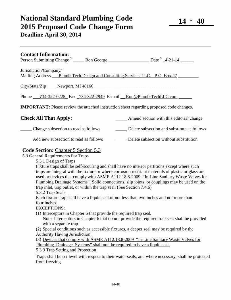
National Standard Plumbing Code 2015 Proposed Code Change Form Deadline April 30, 2014
14 - 40
14-40
Contact Information: Person Submitting Change 2 _____ Ron George __________________ Date 3 _4-21-14 ______ Jurisdiction/Company/ Mailing Address ___Plumb-Tech Design and Consulting Services LLC. P.O. Box 47 _________ City/State/Zip ____ Newport, MI 48166______________________________________ Phone ___734-322-0225_ Fax _734-322-2949 E-mail __ [email protected] ______ IMPORTANT: Please review the attached instruction sheet regarding proposed code changes. Check All That Apply: _____ Amend section with this editorial change _____ Change subsection to read as follows _____ Delete subsection and substitute as follows _____ Add new subsection to read as follows _____ Delete subsection without substitution Code Section: Chapter 5 Section 5.3 5.3 General Requirements For Traps
5.3.1 Design of Traps Fixture traps shall be self-scouring and shall have no interior partitions except where such traps are integral with the fixture or where corrosion resistant materials of plastic or glass are used or devices that comply with ASME A112.18.8-2009 “In-Line Sanitary Waste Valves for Plumbing Drainage Systems”. Solid connections, slip joints, or couplings may be used on the trap inlet, trap outlet, or within the trap seal. (See Section 7.4.6) 5.3.2 Trap Seals Each fixture trap shall have a liquid seal of not less than two inches and not more than four inches. EXCEPTIONS: (1) Interceptors in Chapter 6 that provide the required trap seal.
Note: Interceptors in Chapter 6 that do not provide the required trap seal shall be provided with a separate trap.
(2) Special conditions such as accessible fixtures, a deeper seal may be required by the Authority Having Jurisdiction. (3) Devices that comply with ASME A112.18.8-2009 “In-Line Sanitary Waste Valves for
Plumbing Drainage Systems” shall not be required to have a liquid seal. 5.3.3 Trap Setting and Protection Traps shall be set level with respect to their water seals, and where necessary, shall be protected from freezing.

14-40
5.3.4 Building Traps Building traps shall not be installed except where required by the Authority Having Jurisdiction. Each building trap when installed shall be provided with a cleanout and with a relieving vent or fresh air intake on the inlet side of the trap that shall be at least one-half the diameter of the drain to which it connects. Such relieving vent or fresh air intake shall be carried above grade and terminate in a screen outlet located outside the building. 5.3.5 Prohibited Traps
a. The followings types of traps shall be provided: 1. Traps that depend upon moving parts to maintain their seal. 2. Bell traps. 3. Crown vented traps. 4. Separate fixture traps that depend on interior partitions for their seal, except if made from plastic, glass or other corrosion resistant materials.
5. “S” traps or uniform internal dimensions. 6. Drum traps. EXCEPTIONS: Devices that comply with ASME A112.18.8-2009 “In-Line Sanitary Waste Valves for Plumbing Drainage Systems” .
b. Hair interceptors, precious metal interceptors and similar appurtenances shall be permitted as required.
5.3.6 Trap Seal Maintenance a. Traps that could lose their seal due to evaporation because of infrequent use shall have accessible means to replenish the trap seal or be connected to a trap primer conforming to ASSE 1018 or ASSE 1044. b. In addition to the priming requirements of Section 5.3.6.a, floor drains shall be permitted to be fitted with a barrier type floor drain trap seal protection device complying with ASSE 1072.
Basis/Reason for Change: ASME recently developed an industry standard for “In-Line Sanitary Waste Valves for Plumbing Drainage Systems” (ASME A122.18.8-2009). These devices prevent sewer gases from entering a building while also protecting the fixture from evaporation and freezing of a trap.
Vote: ___ Accept ___ Accept as Amended
___ Accept in Part ___ Accept in Principle ___ Accept in Part and Principle
___ Defeated ___Failed Lack of Second ___ Tabled ___ Withdrawn ___ Other ____________________________________________________________________________________

14-41
National Standard Plumbing Code 2015 Proposed Code Change Form
14 - 41
Contact Information: Person Submitting Change NSPC Committee Date 04-30-2014 Mailing Address 180 S. Washington Street, P.O. Box 6808 . City/State/Zip Falls Church, VA 22046 . Phone 1-800-533-7694 Fax 1-703-237-7442 E-mail [email protected] Check All That Apply: ___ Amend section with this editorial change __X_ Change subsection to read as follows ____ Delete subsection and substitute as follows __X_ Add new subsection to read as follows ____ Delete subsection without substitution Code Section: 5.3 REQUIREMENTS FOR TRAPS 5.3.5 Prohibited Traps a. 6. Drum traps, except drum trap solids separators that are permitted in Section 5.3.7. b. Hair interceptors, precious metal interceptors and similar appurtenances shall be permitted as required. 5.3.7 Drum Trap Solids Interceptors a. Drum trap solids interceptors shall be permitted for lavatories and sinks in beauty salons, dental offices, jewelry stores, hotel and motel guest rooms, dormitories and other areas that require interception of hair, solids, and valuables. b. Solids interceptors of the drum trap type shall comply with Section 6.5. c. The depth of trap seals shall comply with Section 5.3.2. 6.5 SOLIDS SEPARATORS d. Drum trap solids separators shall comply with Section 5.3.7. Basis/Reason for Change: To clarify the requirements for the drum trap type of solids separators. Vote: ___ Accept ___ Accept as Amended
___ Accept in Part ___ Accept in Principle ___ Accept in Part and Principle
___ Defeated ___Failed Lack of Second ___ Tabled ___ Withdrawn ___ Other ______________________________________________________________________________

14-42
National Standard Plumbing Code 2015 Proposed Code Change Form
14 - 42
Contact Information: Person Submitting Change NSPC Committee Date 04-30-2014 Mailing Address 180 S. Washington Street, P.O. Box 6808 . City/State/Zip Falls Church, VA 22046 . Phone 1-800-533-7694 Fax 1-703-237-7442 E-mail [email protected] Check All That Apply: ___ Amend section with this editorial change __X_ Change subsection to read as follows ____ Delete subsection and substitute as follows ____ Add new subsection to read as follows ____ Delete subsection without substitution Code Section: 5.4 DRAINAGE PIPE CLEANOUTS 5.4.6 Building Drain and Building Sewer Junctions and the Property Line a. There shall be a cleanout near the junction of a building drain and building sewer either inside or outside the building wall. b. Cleanouts shall be placed in the building sanitary sewer and the building storm sewer at the property line and brought to the surface in accordance with the requirements of the Adopting Agency Authority Having Jurisdiction. See Figures 5.4.6-A and 5.4.6-B Basis/Reason for Change: The requirements for how to bring cleanouts to the surface are not normally included in the plumbing code requirements adopted by the Adopting Agency. The Authority Having Jurisdiction usually deals with the specific conditions for individual projects. Vote: ___ Accept ___ Accept as Amended
___ Accept in Part ___ Accept in Principle ___ Accept in Part and Principle
___ Defeated ___Failed Lack of Second ___ Tabled ___ Withdrawn ___ Other ______________________________________________________________________________

14-43
National Standard Plumbing Code 2015 Proposed Code Change Form
14 - 43
Contact Information: Person Submitting Change NSPC Committee Date 04-30-2014 . Mailing Address 180 S. Washington Street, P.O. Box 6808 . City/State/Zip Falls Church, VA 22046 . Phone 1-800-533-7694 Fax 1-703-237-7442 E-mail [email protected] Check All That Apply: ___ Amend section with this editorial change __X_ Change subsection to read as follows ____ Delete subsection and substitute as follows _ ___ Add new subsection to read as follows ____ Delete subsection without substitution Code Section: 5.5 BACKWATER VALVES 5.5.1 Where Required d. Other portions of the drainage system not subject to such backflow shall not drain through a backwater valve. See Figure 5.5.1. EXCEPTION: Existing buildings without backwater valves that have fixtures that are
below the overflow level of the public sewer shall be permitted to install backwater valves in piping that also serves fixtures that are above the overflow level of the sewer if necessary to protect the fixtures that are below the overflow level.
Basis/Reason for Change: To permit the installation of backwater valves in existing piping that serves fixtures not subject to backflow where necessary to protect existing fixtures that are subject to backflow. Vote: ___ Accept ___ Accept as Amended
___ Accept in Part ___ Accept in Principle ___ Accept in Part and Principle
___ Defeated ___Failed Lack of Second ___ Tabled ___ Withdrawn ___ Other ______________________________________________________________________________

14-44
National Standard Plumbing Code 2015 Proposed Code Change Form ____________________________________________________________
14 - 44
Contact Information: Person Submitting Change NSPC Committee Date 03-27-2014 . Mailing Address 180 S. Washington Street, P.O. Box 6808 . City/State/Zip Falls Church, VA 22046 . Phone 1-800-533-7694 Fax 1-703-237-7442 E-mail [email protected] Check All That Apply: ___ Amend section with this editorial change __X_ Change subsection to read as follows ____ Delete subsection and substitute as follows ____ Add new subsection to read as follows ____ Delete subsection without substitution Code Section: Chapter 6 Liquid Waste Treatment Equipment 6.1.4.1 General The type, size, capacity, design, arrangement, construction, and installation of liquid waste treatment devices shall be as approved required by the Authority Having Jurisdiction. 6.1.7 Point of Discharge Connections to sewers or other points of discharge for the effluent from liquid waste treatment equipment shall be as approved permitted by the Authority Having Jurisdiction. 6.2.7 Location Hydro-mechanical and GRD interceptors shall be permitted to may be installed within buildings unless otherwise prohibited by the Adopting Agency if permitted by the Authority Having Jurisdiction. F.2 REFERENCES 6.1.4.1 Design and installation of liquid waste treatment equipment. 6.1.7 Point of discharge of liquid waste treatment equipment. 6.2.7 Indoor grease interceptors. Basis/Reason for Change: To clarify the requirements for liquid waste treatment equipment. Vote: ___ Accept ___ Accept as Amended
___ Accept in Part ___ Accept in Principle ___ Accept in Part and Principle
___ Defeated ___Failed Lack of Second ___ Tabled ___ Withdrawn ___ Other ______________________________________________________________________________

14-45
National Standard Plumbing Code 2015 Proposed Code Change Form
14 - 45
Contact Information: Person Submitting Change NSPC Committee Date 04-30-2014 . Mailing Address 180 S. Washington Street, P.O. Box 6808 . City/State/Zip Falls Church, VA 22046 . Phone 1-800-533-7694 Fax 1-703-237-7442 E-mail [email protected] Check All That Apply: ___ Amend section with this editorial change __X_ Change subsection to read as follows ____ Delete subsection and substitute as follows ____ Add new subsection to read as follows ____ Delete subsection without substitution Code Section: 7.2 FIXTURES FOR ACCESSIBLE USE a. Plumbing fixtures for accessible use and their installation shall conform to the requirements of the 2010 ADA Standards for Accessible Design, ICC ANSI A117.1, or in accordance with the local accessibility code or regulations.
Comment: Typical requirements for accessible plumbing fixtures are in ADA Standards for Accessible Design and ICC ANSI A117.1. Refer to local codes and regulations.
b. Exposed waste and water supply piping for accessible sinks and lavatories shall be covered with protectors or insulators that comply with ASME A112.18.9. c. The support and drain systems for adjustable sinks that facilitate accessible use shall comply with ASME A112.19.12. Basis/Reason for Change: To clarify the requirements for accessible plumbing fixtures and their installation, which are located in local codes. To add the requirement for ASME A112.19.12 support and drain systems for adjustable sinks. Vote: ___ Accept ___ Accept as Amended
___ Accept in Part ___ Accept in Principle ___ Accept in Part and Principle
___ Defeated ___Failed Lack of Second ___ Tabled ___ Withdrawn ___ Other ______________________________________________________________________________

14-46
National Standard Plumbing Code 2015 Proposed Code Change Form
14 - 46
Contact Information: Person Submitting Change NSPC Committee Date 02-10-2014 . Mailing Address 180 S. Washington Street, P.O. Box 6808 . City/State/Zip Falls Church, VA 22046 . Phone 1-800-533-7694 Fax 1-703-237-7442 E-mail [email protected] Check All That Apply: ___ Amend section with this editorial change __X_ Change subsection to read as follows ____ Delete subsection and substitute as follows ____ Add new subsection to read as follows ____ Delete subsection without substitution Code Section: 7.3.5 Supporting Wall-Hung Fixtures a. Wall-hung water closets shall be supported by concealed metal carriers that transmit the entire weight of the fixture to the floor and place no strain on the wall or connecting piping. Supports of this design shall comply with ASME A112.6.1M. b. Supports for off-the-floor water closets with concealed tanks shall comply with ASME A112.6.2. b. c. Free-standing lavatories, wall-hung urinals, water closets with or without concealed tanks Lavatories, urinals, and other wall-mounted wall-hung fixtures shall be supported by a concealed or exposed finished wall hanger plate or equivalent that transmits the weight of the fixture to the wall structure, if adequate, or to the floor without placing strain on the piping. Such supports shall comply with ASME A112.6.2 or ASME A112.19.12. ASME A112.6.1M or equivalent. In addition to the wall support brackets, pedestals or legs may provide additional support for pedestal lavatories. Basis/Reason for Change: To clarify the requirements for supports for wall hung fixtures. Vote: ___ Accept ___ Accept as Amended
___ Accept in Part ___ Accept in Principle ___ Accept in Part and Principle
___ Defeated ___Failed Lack of Second ___ Tabled ___ Withdrawn ___ Other ______________________________________________________________________________

14-47
National Standard Plumbing Code 2015 Proposed Code Change Form
14 - 47
Contact Information: Person Submitting Change NSPC Committee Date 3-06-2014 . Mailing Address 180 S. Washington Street, P.O. Box 6808 . City/State/Zip Falls Church, VA 22046 . Phone 1-800-533-7694 Fax 1-703-237-7442 E-mail [email protected] Check All That Apply: ___ Amend section with this editorial change __X_ Change subsection to read as follows ____ Delete subsection and substitute as follows ____ Add new subsection to read as follows ____ Delete subsection without substitution Code Section: 7.4.4 Bowl Height The height of water closet bowls shall be a minimum of 13-1/2 inches 13-1/2 to 17 inches from the finished floor to the top of the rim. EXCEPTIONS EXCEPTION: (1) Bowls intended for children's use (5 years and younger) are permitted to be 9-1/2" to 10-1/2" high to the rim and juvenile use (6-12 years) are permitted to be 10-1/2" to 13-1/2" to the rim. (2) The height of bowls intended specifically for children's accessible use (12 years and younger) shall be such that the top of the rim is 11" to 17" above the floor and comply with Section 7.2. (3) The height of bowls intended for adult accessible use (13 years and older) shall be such that the top of the seat is 17" to 19" above the floor and comply with Section 7.2. Delete Figure 7.4.4 - A Permitted Heights of Water Closet Bowls for Childrens Use Delete Figure 7.4.4 - B Permitted Height of Water Closet Bowls for Adult Accessible Use Basis/Reason for Change: To delete specific accessibility requirements from the plumbing code. Vote: ___ Accept ___ Accept as Amended
___ Accept in Part ___ Accept in Principle ___ Accept in Part and Principle
___ Defeated ___Failed Lack of Second ___ Tabled ___ Withdrawn ___ Other ______________________________________________________________________________

14-48
National Standard Plumbing Code 2015 Proposed Code Change Form
14 - 48
Contact Information: Person Submitting Change NSPC Committee Date 3-02-2014 . Mailing Address 180 S. Washington Street, P.O. Box 6808 . City/State/Zip Falls Church, VA 22046 . Phone 1-800-533-7694 Fax 1-703-237-7442 E-mail [email protected] Check All That Apply: ___ Amend section with this editorial change __X_ Change subsection to read as follows ____ Delete subsection and substitute as follows ____ Add new subsection to read as follows ____ Delete subsection without substitution Code Section: 7.4.8 Macerating Toilet Systems Water Closets with Pumps Macerating toilet systems and related components shall comply with ASME A112.3.4 or CSA B45.9. Water closets with pumps shall comply with ASME A112.3.4/CSA B45.9. Table 3.1.3 - Part V PLUMBING FIXTURES Plumbing fixtures with pumped waste …………………………………… ASME A112.3.4 CSA B45.9 Basis/Reason for Change: ASME A112.3.4 and CSA B45.9 have been combined for plumbing fixtures with pumped waste, macerating toilet systems, and related components. The requirements for macerating toilet systems are in Section 11.7.6. Vote: ___ Accept ___ Accept as Amended
___ Accept in Part ___ Accept in Principle ___ Accept in Part and Principle
___ Defeated ___Failed Lack of Second ___ Tabled ___ Withdrawn ___ Other ______________________________________________________________________________

14-49
National Standard Plumbing Code 2015 Proposed Code Change Form
14 - 49
Contact Information: Person Submitting Change NSPC Committee Date 04-30-2014 . Mailing Address 180 S. Washington Street, P.O. Box 6808 . City/State/Zip Falls Church, VA 22046 . Phone 1-800-533-7694 Fax 1-703-237-7442 E-mail [email protected] Check All That Apply: ___ Amend section with this editorial change __X_ Change subsection to read as follows ____ Delete subsection and substitute as follows ____ Add new subsection to read as follows ____ Delete subsection without substitution Code Section: 7.5 URINALS 7.5.1 Compliance a. Water-fed vitreous china urinals shall comply with ASME A112.19.2/CSA B45.1. b. Non-water vitreous china urinals shall comply with ASME A112.19.19/CSA B45.4. c. Water-fed and non-water Plastic urinals shall comply with CSA B45.5/IAPMO Z124. d. Non-water urinals shall have a liquid trap seal as required by Section 5.3.2. e. Water-fed urinals with a concealed trap seal and/or an outlet strainer liquid trap seals that are not visible in the bowl shall be supplied by an automatic flushing device. Basis/Reason for Change: To update the compliance requirements for urinals. Vote: ___ Accept ___ Accept as Amended
___ Accept in Part ___ Accept in Principle ___ Accept in Part and Principle
___ Defeated ___Failed Lack of Second ___ Tabled ___ Withdrawn ___ Other ______________________________________________________________________________

14-50
National Standard Plumbing Code 2015 Proposed Code Change Form
14 - 50
Contact Information: Person Submitting Change NSPC Committee Date 04-07-2014 . Mailing Address 180 S. Washington Street, P.O. Box 6808 . City/State/Zip Falls Church, VA 22046 . Phone 1-800-533-7694 Fax 1-703-237-7442 E-mail [email protected] Check All That Apply: ___ Amend section with this editorial change __X_ Change subsection to read as follows ____ Delete subsection and substitute as follows ____ Add new subsection to read as follows ____ Delete subsection without substitution Code Section: 7.6 LAVATORIES 7.6.1 Compliance a. Lavatories shall comply with the following standards: 1. Ceramic, non-vitreous; ASME A112.19.2/CSA B45.1 2. Enamled cast iron; ASME A112.19.1/CSA B45.2 3. Enameld steel; ASME A112.19.1/CSA B45.2 4. Plastic; CSA B45.5/IAPMO Z124 5. Stainless steel; ASME A112.19.3/CSA B45.4 6. Vitreous china; ASME A112.19.2/CSA B45.1 b. Lavatory faucets shall provide air gaps that comply with ASME A112.1.2 or Table 10.5.2 Basis/Reason for Change: To include the requirement that lavatory faucets provide the necessary air gaps. Vote: ___ Accept ___ Accept as Amended
___ Accept in Part ___ Accept in Principle ___ Accept in Part and Principle
___ Defeated ___Failed Lack of Second ___ Tabled ___ Withdrawn ___ Other ______________________________________________________________________________

14-51
National Standard Plumbing Code 2015 Proposed Code Change Form
14 - 51
Contact Information: Person Submitting Change NSPC Committee Date 03-31-2014 . Mailing Address 180 S. Washington Street, P.O. Box 6808 . City/State/Zip Falls Church, VA 22046 . Phone 1-800-533-7694 Fax 1-703-237-7442 E-mail [email protected] Check All That Apply: ___ Amend section with this editorial change __X_ Change subsection to read as follows ____ Delete subsection and substitute as follows ____ Add new subsection to read as follows ____ Delete subsection without substitution Code Section: 7.6.5 WASH FOUNTAINS AND WASH SINKS Table 5.2 MINIMUM SIZE OF NON-INTEGRAL TRAPS Trap Size in Inches Lavatory, multiple type (wash fountain or wash sink)…………..1-1/2 Wash Fountain (4 rated users or less)………..…………………..1-1/2 Wash Fountain (8 rated users or less)…………………………….. 2 Wash Sink……………………………………………………….1-1/2 Table 10.4.1 WATER SUPPLY FIXTURE UNITS (WSFU) Other Than Dwelling Units Wash Fountain (per rated user) ……………………………….…. 0.5 Wash Sink (1 or 2 faucets, per faucet) ………………….………. 1.0 Wash Sink (additional faucets, per faucet) ….……………….…. 0.5 Table 11.4.1 DRAINAGE FIXTURE UNIT (DFU) VALUES Other Than Dwelling Units Wash Fountain, 1-1/2” Trap ………………………....……………. 2 Wash Fountain. 2” Trap …………………………………………… 3 Wash Sink, each set of Faucets ……………………..….……….. 2 1

14-51
7.6.5 Wash Fountains and Wash Sinks a. Circular and semi-circular wash fountains and wall-mounted and free-standing wash sinks shall comply with the requirement of Section 7.6. Mixed water temperature control shall comply with Section 10.15.6. b. The water supply to wash fountains shall not exceed 0.75 gpm for each of the rated number of users. The rated number of users for wash fountains shall be as specified by the manufacturer but shall not be more than one person per 18-inches of usable length of the rim having an available water spray. See Figure 7.6.7 c. The faucets for wash sinks shall comply with Section 7.6.2 for lavatories. The rated number of users for wash sinks shall equal the number of faucets. 7.6.5 7.6.7 Lavatory Equivalents Where group-type wash fountains or wash sinks are used to satisfy the number of lavatories required by Section 7.21.1, each 18-inch usable length of rim having an available water spray rated user shall be considered as the equivalent of one lavatory. See Figure 7.6.5 Figure 7.6.5 7.6.7 A CIRCULAR WASH FOUNTAIN Basis/Reason for Change: To add the requirements for wash fountains and wash sinks. Vote: ___ Accept ___ Accept as Amended
___ Accept in Part ___ Accept in Principle ___ Accept in Part and Principle
___ Defeated ___Failed Lack of Second ___ Tabled ___ Withdrawn ___ Other ______________________________________________________________________________

14-52
National Standard Plumbing Code 2015 Proposed Code Change Form
14 - 52
Contact Information: Person Submitting Change NSPC Committee Date 04-30-2014 Mailing Address 180 S. Washington Street, P.O. Box 6808 . City/State/Zip Falls Church, VA 22046 . Phone 1-800-533-7694 Fax 1-703-237-7442 E-mail [email protected] Check All That Apply: ___ Amend section with this editorial change __X_ Change subsection to read as follows ____ Delete subsection and substitute as follows ____ Add new subsection to read as follows ____ Delete subsection without substitution Code Section: 7.8 BATHTUBS 7.8.2 Waste and Overflow a. Bathtubs shall have waste outlet and overflow pipes not less than 1-1/2” nominal size. Waste outlets shall be equipped with a pop-up waste, chain and stopper, or other type of drain plug. See Figure 7.8.2 b. Where tub waste and overflow piping includes slip joints that do not provide a rigid joint when made up, an access panel shall be provided as required by Section 4.2.15. c. An access panel shall be provided for tub overflow fittings that have flexible gaskets that are not accessible from within the tub. d. Tub waste and overflow assemblies that are designed by the manufacturer for concealed installations shall not require an access panel. Basis/Reason for Change: To indicate the possible requirement for access panels for tub waste and overflows. Vote: ___ Accept ___ Accept as Amended
___ Accept in Part ___ Accept in Principle ___ Accept in Part and Principle
___ Defeated ___Failed Lack of Second ___ Tabled ___ Withdrawn ___ Other ______________________________________________________________________________

14-53
National Standard Plumbing Code 2015 Proposed Code Change Form
14 - 53
Contact Information: Person Submitting Change NSPC Committee Date 04-30-2014 . Mailing Address 180 S. Washington Street, P.O. Box 6808 . City/State/Zip Falls Church, VA 22046 . Phone 1-800-533-7694 Fax 1-703-237-7442 E-mail [email protected] Check All That Apply: ___ Amend section with this editorial change __X_ Change subsection to read as follows ____ Delete subsection and substitute as follows ____ Add new subsection to read as follows ____ Delete subsection without substitution Code Section: 7.8 BATHTUBS 7.8.4 Backflow Prevention Unless equipped with an ASSE 1001 atmospheric backflow preventer vacuum breaker, in accordance with ASSE 1001 or ASME A112.18.7, the bathtub filler shall be equpped with an air gap between the end of the over-rim tub filler spout there shall be an air gap between the outlet of the bath spout and the overflow flood level rim of the tub that complies with Section 10.5 Section 10.5.2 and Table 10.5.2. Basis/Reason for Change: To clarify the backflow prevention requirements for bathtubs. ASME A112.18.7 for deck mounted bath/shower transfer valves with internal backflow prevention has been withdrawn. Vote: ___ Accept ___ Accept as Amended
___ Accept in Part ___ Accept in Principle ___ Accept in Part and Principle
___ Defeated ___Failed Lack of Second ___ Tabled ___ Withdrawn ___ Other ______________________________________________________________________________

14-54
National Standard Plumbing Code 2015 Proposed Code Change Form
14 - 54
Contact Information: Person Submitting Change NSPC Committee Date 02-19-2014 . Mailing Address 180 S. Washington Street, P.O. Box 6808 . City/State/Zip Falls Church, VA 22046 . Phone 1-800-533-7694 Fax 1-703-237-7442 E-mail [email protected] Check All That Apply: ___ Amend section with this editorial change __X_ Change subsection to read as follows ____ Delete subsection and substitute as follows ____ Add new subsection to read as follows ____ Delete subsection without substitution Code Sections: 7.9 WHIRLPOOL BATHS 7.9.2 Compliance Whirlpool bathtubs and their suction fittings shall comply with ASME A112.19.7/CSA B45.10. Basis/Reason for Change: To update the standards for whirlpool baths. Vote: ___ Accept ___ Accept as Amended
___ Accept in Part ___ Accept in Principle ___ Accept in Part and Principle
___ Defeated ___Failed Lack of Second ___ Tabled ___ Withdrawn ___ Other ______________________________________________________________________________

14-55
National Standard Plumbing Code 2015 Proposed Code Change Form
14 - 55
Contact Information: Person Submitting Change NSPC Committee Date 4-22-2014 . Mailing Address 180 S. Washington Street, P.O. Box 6808 . City/State/Zip Falls Church, VA 22046 . Phone 1-800-533-7694 Fax 1-703-237-7442 E-mail [email protected] Check All That Apply: ___ Amend section with this editorial change __X_ Change subsection to read as follows ____ Delete subsection and substitute as follows ____ Add new subsection to read as follows ____ Delete subsection without substitution Code Section: 7.10.4 Shower Waste Outlets a. For a shower with a single 2.5 gpm shower head, the waste outlet connection shall be sized for a drain not less than 1-1/2 inches nominal pipe size. Combination bath/showers with 1-1/2” drains can have two 2.5 gpm shower heads. b. Showers with multiple shower heads shall have a 2” outlet pipe size for up to 10 gpm and a 3” outlet pipe size for up to 20 gpm, and 4” outlet pipe size for up to 50 gpm. Multiple waste outlets shall be provided where necessary to handle the total water flow from the shower heads. EXCEPTION: Bathtubs with multiple shower heads. c. (No change) d. (No change) e. (No change) Basis/Reason for Change: To coordinate Section 7.10.4 with the changes in the DFU values for shower stalls in Table 11.4.1. Vote: ___ Accept ___ Accept as Amended
___ Accept in Part ___ Accept in Principle ___ Accept in Part and Principle
___ Defeated ___Failed Lack of Second ___ Tabled ___ Withdrawn ___ Other ______________________________________________________________________________

14-56
National Standard Plumbing Code 2015 Proposed Code Change Form
14 - 56
Contact Information: Person Submitting Change NSPC Committee Date 02-22-2014 . Mailing Address 180 S. Washington Street, P.O. Box 6808 . City/State/Zip Falls Church, VA 22046 . Phone 1-800-533-7694 Fax 1-703-237-7442 E-mail [email protected] Check All That Apply: ___ Amend section with this editorial change _____ Change subsection to read as follows ____ Delete subsection and substitute as follows __X_ Add new subsection to read as follows ____ Delete subsection without substitution Code Section: 7.10.6 Shower Floors and Shower Pan Liners f. Shower pan liners shall be tested for leakage. The shower drain pipe shall be plugged watertight beyond the drain fitting. The shower floor shall be filled with clear water to a depth of not less than 2 inches measured at the threshold. There shall be no leakage indicated on the floor surrounding the shower pan for a period of not less than 30 minutes. Basis/Reason for Change: To require that shower pans be tested for leakage. Vote: ___ Accept ___ Accept as Amended
___ Accept in Part ___ Accept in Principle ___ Accept in Part and Principle
___ Defeated ___Failed Lack of Second ___ Tabled ___ Withdrawn ___ Other ______________________________________________________________________________

14-57
National Standard Plumbing Code 2015 Proposed Code Change Form
14 - 57
Contact Information: Person Submitting Change NSPC Committee Date 04-30-2014 . Mailing Address 180 S. Washington Street, P.O. Box 6808 . City/State/Zip Falls Church, VA 22046 . Phone 1-800-533-7694 Fax 1-703-237-7442 E-mail [email protected] Check All That Apply: ___ Amend section with this editorial change _X__ Change subsection to read as follows ____ Delete subsection and substitute as follows ____ Add new subsection to read as follows ____ Delete subsection without substitution Code Section: 7.11 SINKS 7.11.1 Compliance a. Sinks shall comply with the following standards: 1. Enameled cast-iron; ASME A112.19.1/CSA B45.2 2. Enameled steel; ASME A112.19.1/CSA B45.2 3. Stainless steel; ASME A112.19.3/CSAB45.4. 4. Plastic; CSA B45.5/IAPMO Z124 5. Ceramic; ASME A112.19.2/CSA B45.1 b. Fixture supply fittings, including faucets and supply stops, shall comply with ASME A112.18.1/CSA B125.1. c. Fixture waste outlet fittings shall comply with ASME A112.18.2/CSA B125.2. 7.11. 2 Domestic Kitchen Sinks and Bar Sinks
a. Each compartment in a kitchen sink or bar sink shall have an outlet suitable for either a domestic food waste grinder or a basket strainer. The waste outlet pipe for each compartment shall be 1-1/2" nominal size. Outlet fittings shall have crossbars or other provisions for protecting the drain outlet and shall include a means of closing the drain outlet. b. Faucets for kitchen sinks and bar sinks shall be designed and manufactured so that they will not exceed a water flow rate of 2.2 gallons per minute when tested in accordance with ASME A112.18.1/CSA B125.1. See Figure 7.11.2 7.11.3 Laundry Tubs and Sinks a. Sinks Tub and sink compartments for laundry use shall be not less than 12 inches deep with a strainer and waste outlet not less than 1-1/2" nominal size. b. Utility faucets for laundry sinks shall comply with ASME A112.18.2/CSA B125.1 Supply fittings shall have a rated minimum flow rate of 4.0 gpm.

14-57
7.11.4 Service Sinks and Mop Receptors a. Service sinks and mop receptors shall have removable strainers and waste outlet connections not less than 2" nominal size. b. Supply fittings shall have a rated minimum flow rate of 4.0 gpm. b. c. Service sinks and mop receptors shall not be installed where walls and floors are not waterproof and do not have a smooth, readily cleanable surface at least one foot in front of the sink or receptor, at least one foot on each side, and up to a point one foot above the faucet height. 7.11.5 Sink Faucets 7.11.6 Backflow Prevention a. Sink faucets having a hose thread or other means of attaching a hose to the outlet shall be protected from back-siphonage back siphonage by either an integral vacuum breaker, an atmospheric vacuum breaker attached to the outlet, or pressure type vacuum breakers on the fixture supply lines. b. Faucets for kitchen sinks shall be designed and manufactured so that they will not exceed the flow rate for kitchen sinks specified in ASME A112.18.1/CSA B125.1. b. Sink faucets without provisions for connecting hoses shall be protected from back siphonage by a fixed air gap complying with ASME A112.1.2 or Table 10.5.2. 7.11.5 Sanitary Floor Sinks Sanitary floor sinks shall comply with ASME A112.6.7. Basis/Reason for Change: To update the requirements for sinks. Vote: ___ Accept ___ Accept as Amended
___ Accept in Part ___ Accept in Principle ___ Accept in Part and Principle
___ Defeated ___Failed Lack of Second ___ Tabled ___ Withdrawn ___ Other ______________________________________________________________________________

14-58
National Standard Plumbing Code 2015 Proposed Code Change Form
14 - 58
Contact Information: Person Submitting Change NSPC Committee Date 04-30-2014 . Mailing Address 180 S. Washington Street, P.O. Box 6808 . City/State/Zip Falls Church, VA 22046 . Phone 1-800-533-7694 Fax 1-703-237-7442 E-mail [email protected] Check All That Apply: ___ Amend section with this editorial change __X_ Change subsection to read as follows ____ Delete subsection and substitute as follows ____ Add new subsection to read as follows ____ Delete subsection without substitution Code Section: 7.12 DRINKING FOUNTAINS AND WATER COOLERS
DRINKING WATER FACILITIES 7.12.1 Compliance Refrigerated drinking fountains and water coolers shall comply with ARI 1010 and UL 399.
7.12.2 Prohibited Locations Drinking fountains and water coolers shall not be located in public toilet rooms. EXCEPTION: Convertible lavatory faucets and fixture fittings that provide a discharge stream similar to a drinking fountain shall be permitted in bathrooms in dwelling units.
7.12.3 Outdoor Drinking Fountains Freeze-resistant drinking fountains shall be the sanitary type. Weep hole drains that form a cross connection between ground water and the potable water supply shall not be permitted. 7.12.1 Compliance a. Drinking water facilities shall comply with the “lead-free” requirements of Section 3.4.6.
b. Drinking water facilities for accessible use shall comply with Section 7.2.
c. Drinking fountains shall comply with the following plumbing fixture standards:
1) enameled cast iron or steel: ASME A112.19.1/CSA B45.2
2) ceramic: ASME A112.19.2/CSA B45.1
3) stainless steel: ASME A112.19.3/CSA B45.4
d. Drinking water coolers with self-contained refrigeration units shall comply with UL 399 and ASHRAE Standard 18.
e. Water bottle filling stations shall comply with applicable standards. Stations with self-contained refrigeration units for chilled water shall comply with UL 399 and ASHRAE Standard 18.

14-58
7.12.2 Required Drinking Water Facilities The required drinking water facilities shall be in accordance with Section 7.21. 7.12.3 Prohibited Locations Drinking water facilities shall not be located in public toilet rooms. Convertible lavatory faucets that provide a discharge stream similar to a drinking fountain shall only be permitted in bathrooms in dwelling units. 7.12.4 Outdoor Drinking Fountains Freeze-resistant drinking fountains shall be the sanitary type. Weep hole drains that form a cross connection between ground water and the potable water supply shall not be permitted. Section 1.2 DEFINITION OF TERMS Water Bottle Filling Station: A drinking water supply fixture that is connected to the domestic water supply and drain piping and provides for individuals to fill personal-use water bottles. Stations can be recessed or wall-mounted and can include filtration units, self-contained refrigeration units, and drinking fountains. Table 19.1 Referenced Standards ASHRAE Standard 18 - 2008: Methods of Testing for Rating Drinking-Water Coolers with Self-Contained Mechanical Refrigeration…………………………………………………………7.12.1 Basis/Reason for Change: To update the requirements for drinking water facilities. Water bottle filling stations are popular in colleges and other facilities were people carry personal water bottles during the day. Their use reduces the use of bottled water dispensers and the number of used bottled water containers that end up in landfills. Vote: ___ Accept ___ Accept as Amended
___ Accept in Part ___ Accept in Principle ___ Accept in Part and Principle
___ Defeated ___Failed Lack of Second ___ Tabled ___ Withdrawn ___ Other ______________________________________________________________________________

14-59
National Standard Plumbing Code 2015 Proposed Code Change Form
14 - 59
Contact Information: Person Submitting Change NSPC Committee Date 3-01-2014 . Mailing Address 180 S. Washington Street, P.O. Box 6808 . City/State/Zip Falls Church, VA 22046 . Phone 1-800-533-7694 Fax 1-703-237-7442 E-mail [email protected] Check All That Apply: ___ Amend section with this editorial change __X_ Change subsection to read as follows ____ Delete subsection and substitute as follows ____ Add new subsection to read as follows ____ Delete subsection without substitution Code Section: 7.15 DISHWASHING MACHINES 7.15.1 Compliance a. Domestic dishwashing machines shall comply with UL 749 and AHAM DW-1. The water supply to domestic dishwashing machines shall be protected from back-siphonage by an internal air gap, vacuum breaker, or other internal means. Air gap fittings for drain discharge shall comply with ASSE 1021. b. Commercial dishwashing machines shall comply with UL 921 and NSF 3. Backflow prevention shall comply with ASSE 1004. Table 3.1.3 - Part IX BACKFLOW PREVENTION Domestic dishwasher discharge air gap fittings ……….………………….ASSE 1021 Basis/Reason for Change: To reference the standard for domestic dishwasher discharge air gaps. Vote: ___ Accept ___ Accept as Amended
___ Accept in Part ___ Accept in Principle ___ Accept in Part and Principle
___ Defeated ___Failed Lack of Second ___ Tabled ___ Withdrawn ___ Other ______________________________________________________________________________

14-60
National Standard Plumbing Code 2015 Proposed Code Change Form
14 - 60
Contact Information: Person Submitting Change NSPC Committee Date 04-30-2014 . Mailing Address 180 S. Washington Street, P.O. Box 6808 . City/State/Zip Falls Church, VA 22046 . Phone 1-800-533-7694 Fax 1-703-237-7442 E-mail [email protected] Check All That Apply: ___ Amend section with this editorial change ____ Change subsection to read as follows ____ Delete subsection and substitute as follows ____ Add new subsection to read as follows ____ Delete subsection without substitution Code Section: 7.16 Floor Drains, Area Drains, and Trench Drains 7.16.1 Compliance Floor drains, area drains, and trench drains shall comply with ASME A112.6.3 or and, if stainless steel, ASME A112.3.1.
7.16.2 Trap Seal and Strainer Grate Free Area and Strainer or Sediment Basket a. Floor drains shall have a water seal of not less than 2 inches and shall be fitted with a removable strainer. The free open area of strainers shall be at least 2/3 of the cross-sectional area of the nominal drain outlet size. The free area of the top grate for floor drains, area drains, and trench drains shall comply with ASME A112.6.3 based on their outlet connection size. Where floor drains and area drains receive other than clear-water waste, they shall include an internal outlet strainer or removable metal sediment basket to retain solids.
b. The trap seal for floor drains shall be not less than 2 inches deep.
b. c. Where infrequently used floor drains are subject to evaporation of their trap seals, they shall either 1) be provided with a 4-inch deep trap seal and have an accessible means to replenish, or 2) be fed from an automatic drain trap seal priming device complying with ASSE 1018 or ASSE 1044, or 3) be fitted with a barrier type floor drain trap seal protection device complying with ASSE 1072. c. d. Where traps are automatically primed, the priming connection shall be above the weir of the trap. See Figures 7.16.2-A through -C 7.16.3 Size of Floor Drains a. Floor drains and their branch discharge piping shall be sized on the basis of their normal, expected flow rate in accordance with Section 11.4.4. Floor drains shall be not less than 2” nominal pipe size. b. If provided for emergency showers and eyewash stations, floor drains and their fixture drain branches shall be sized for the GPM discharge capacity of the shower or eyewash, but the drainage fixture unit (DFU) loading on the sanitary drainage system shall be zero (0.0 DFU).

14-60
7.16.4 Required Locations for Floor Drains a. Floor drains shall be located provided in the following areas:
1. Toilet rooms containing either two or more water closets or wall hung urinals or a combination of one or more water closets and wall hung urinals one water closet and one wall hung urinal, two or more water closets, or two or more wall hung urinals, except in a dwelling unit. 2. Commercial kitchens. 3. Common laundry rooms. in commercial buildings and building having more than two dwelling units
7.16.5 Walk-in Coolers and Freezers Floor drains located in walk-in coolers and walk-in freezers where food or other products for human consumption are stored shall be indirectly connected to the drainage system in accordance with Section 9.1.6. 7.16.6 Floor Slope Where floor drains receive indirect waste or other drainage on a regular or frequent basis, the elevation of the floor drain shall be set so that the floor within a 2 foot radius can be sloped to the drain. 1.2 Common Laundry Room: A laundry facility for personal use by multiple individuals. Basis/Reason for Change: To update and clarify the requirements for floor drains and area drains. Vote: ___ Accept ___ Accept as Amended
___ Accept in Part ___ Accept in Principle ___ Accept in Part and Principle
___ Defeated ___Failed Lack of Second ___ Tabled ___ Withdrawn ___ Other ______________________________________________________________________________

14-61
National Standard Plumbing Code 2015 Proposed Code Change Form
14 - 61
Contact Information: Person Submitting Change NSPC Committee Date 02-09-2014 . Mailing Address 180 S. Washington Street, P.O. Box 6808 . City/State/Zip Falls Church, VA 22046 . Phone 1-800-533-7694 Fax 1-703-237-7442 E-mail [email protected] Check All That Apply: ___ Amend section with this editorial change __X_ Change subsection to read as follows ____ Delete subsection and substitute as follows ____ Add new subsection to read as follows ____ Delete subsection without substitution Code Section: 7.18 SPECIAL INSTALLATIONS 7.18.1 Protection of Water Supply The water supply to special installations shall be protected from backflow in accordance with Chapter 10 Sections 10.4.3 and 10.5. Examples of such special installations include decorative fountains, ornamental pools and waterfalls, swimming and wading pools, baptisteries, and similar custom-built equipment. Basis/Reason for Change: To make specific references to Chapter 10 for the backflow prevention requirements. To include waterfalls with ornamental pools. Vote: ___ Accept ___ Accept as Amended
___ Accept in Part ___ Accept in Principle ___ Accept in Part and Principle
___ Defeated ___Failed Lack of Second ___ Tabled ___ Withdrawn ___ Other ______________________________________________________________________________

14-62
National Standard Plumbing Code 2015 Proposed Code Change Form
14 - 62
Contact Information: Person Submitting Change NSPC Committee Date 02-28-2014 . Mailing Address 180 S. Washington Street, P.O. Box 6808 . City/State/Zip Falls Church, VA 22046 . Phone 1-800-533-7694 Fax 1-703-237-7442 E-mail [email protected] Check All That Apply: ___ Amend section with this editorial change __X_ Change subsection to read as follows ____ Delete subsection and substitute as follows ____ Add new subsection to read as follows ____ Delete subsection without substitution Code Section: 7.19 FLUSHING DEVICES FOR WATER CLOSETS AND URINALS 7.19.4 Flushometer Tanks (Pressure Assisted) Flushometer tanks (pressure assisted) shall comply with ASSE 1037 or CSA B125.3 and shall include built-in pressure regulation and backflow prevention devices. 7.19.5 Flushometer Valves Flushometer valves shall comply with ASSE 1037 or CSA B125.3 and include a vacuum breaker assembly and means of flow adjustment. Flushometer valves shall be accessible for maintenance and repair. See Figure 7.19.5 Basis/Reason for Change: Flushometers are within the scope of CSA B125.3 - Plumbing Fittings. ASME A112.19.6 - Hydraulic Requirements for Water Closets and Urinals was incorprated into and replaced by ASME A112.19.2/CSA B45.1 - Ceramic Plumbing Fixtures in 2003 and is no longer listed by ASME. Vote: ___ Accept ___ Accept as Amended
___ Accept in Part ___ Accept in Principle ___ Accept in Part and Principle
___ Defeated ___Failed Lack of Second ___ Tabled ___ Withdrawn ___ Other ______________________________________________________________________________

14-63
National Standard Plumbing Code 2015 Proposed Code Change Form
14 - 63
Contact Information: Person Submitting Change NSPC Committee Date 04-30-2014 Mailing Address 180 S. Washington Street, P.O. Box 6808 . City/State/Zip Falls Church, VA 22046 . Phone 1-800-533-7694 Fax 1-703-237-7442 E-mail [email protected] Check All That Apply: ___ Amend section with this editorial change __X_ Change subsection to read as follows ____ Delete subsection and substitute as follows ____ Add new subsection to read as follows ____ Delete subsection without substitution Code Section: 7.21 MINIMUM NUMBER OF REQUIRED FIXTURES 7.21 MINIMUM NUMBER OF REQUIRED FIXTURES REQUIRED PLUMBING FACILITIES 7.21.1 Number of Fixtures Minimum Number of Required Plumbing Fixtures 7.21.5.c Laundry Trays Facilities: Multiple dwelling units or and boarding houses without public common laundry rooms shall not require laundry trays facilities. Basis/Reason for Change: To clarify the title of Section 7.21 and the requirements for laundry facilities. Vote: ___ Accept ___ Accept as Amended
___ Accept in Part ___ Accept in Principle ___ Accept in Part and Principle
___ Defeated ___Failed Lack of Second ___ Tabled ___ Withdrawn ___ Other ______________________________________________________________________________

14-64
National Standard Plumbing Code 2015 Proposed Code Change Form
14 - 64
Contact Information: Person Submitting Change NSPC Committee Date 04-30-2014 Mailing Address 180 S. Washington Street, P.O. Box 6808 . City/State/Zip Falls Church, VA 22046 . Phone 1-800-533-7694 Fax 1-703-237-7442 E-mail [email protected] Check All That Apply: ___ Amend section with this editorial change __X_ Change subsection to read as follows ____ Delete subsection and substitute as follows ____ Add new subsection to read as follows ____ Delete subsection without substitution Code Section: 7.21 MINIMUM NUMBER OF REQUIRED PLUMBING FIXTURES 7.21.6 Fixture Requirements for Special Occupancies a. Additional fixtures may be required when unusual environmental conditions or special activities are encountered by the use and occupancy regulations for a facility. e. Hand washing facilities shall be provided in each examination room in a doctor’s office or medical office if required by the use and occupancy regulations for a facility. Basis/Reason for Change: To clarify that specific requirements for plumbing fixtures may be included in the local regulations for the administration, permitting, and licensing of specific occupancies. Vote: ___ Accept ___ Accept as Amended
___ Accept in Part ___ Accept in Principle ___ Accept in Part and Principle
___ Defeated ___Failed Lack of Second ___ Tabled ___ Withdrawn ___ Other ______________________________________________________________________________

National Standard Plumbing Code 2015 Proposed Code Change Form Deadline April 30, 2014
14 - 65
14-65
Contact Information: Person Submitting Change 2 _____ Michael G. Baker____________ Date 3 ___March 12, 2014___ Jurisdiction/Company/ Mailing Address __President, New Jersey Plumbing Inspectors Association _______________ City/State/Zip __475 Valley Rd. Wayne, NJ 07470______________________________ Phone __973.694.1800x3287 Fax __973.709.0209 E-mail ____ [email protected] IMPORTANT: Please review the attached instruction sheet regarding proposed code changes. Check All That Apply: _____ Amend section with this editorial change _XX_ Change subsection to read as follows _____ Delete subsection and substitute as follows ____ Add new subsection to read as follows _____ Delete subsection without substitution Code Section: 7.21.6 e e. Hand washing facilities shall be provided in each examination room in a doctor's office or medical office, dental treatment room, massage treatment room, tattoo parlor or any other facility where skin to skin contact is necessary for performing a service. Basis/Reason for Change: The additional facilities would further protect the health and welfare of the general public Vote: ___ Accept ___ Accept as Amended
___ Accept in Part ___ Accept in Principle ___ Accept in Part and Principle
___ Defeated ___Failed Lack of Second ___ Tabled ___ Withdrawn ___ Other ____________________________________________________________________________________

14-66
National Standard Plumbing Code 2015 Proposed Code Change Form
14 - 66
Contact Information: Person Submitting Change NSPC Committee Date 3-01-2014 . Mailing Address 180 S. Washington Street, P.O. Box 6808 . City/State/Zip Falls Church, VA 22046 . Phone 1-800-533-7694 Fax 1-703-237-7442 E-mail [email protected] Check All That Apply: ___ Amend section with this editorial change __X_ Change subsection to read as follows ____ Delete subsection and substitute as follows ____ Add new subsection to read as follows ____ Delete subsection without substitution Code Section: 7.22 WATER TREATMENT SYSTEMS Water softeners, reverse osmosis water treatment units, and other drinking water treatment systems shall meet the requirements of the appropriate standards listed in Table 3.1.3 referenced in Section 10.18.1. Waste discharge from such equipment shall enter the drainage system through an air gap. Discharge piping shall be of a material approved for potable water, sanitary drainage, or storm drainage. Basis/Reason for Change: In the 2013 NSPC Supplement, the specific standards for the various types of drinking water treatment units are listed in Section 10.18.1. Vote: ___ Accept ___ Accept as Amended
___ Accept in Part ___ Accept in Principle ___ Accept in Part and Principle
___ Defeated ___Failed Lack of Second ___ Tabled ___ Withdrawn ___ Other ______________________________________________________________________________
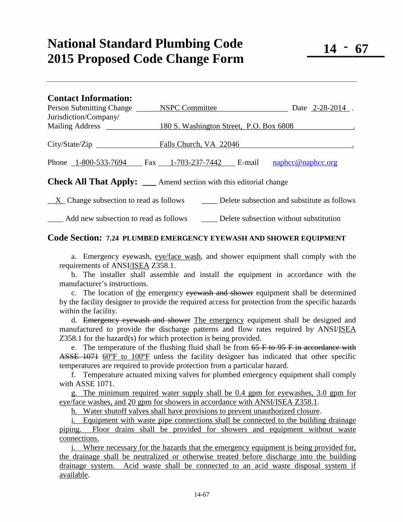
14-67
National Standard Plumbing Code 2015 Proposed Code Change Form
14 - 67
Contact Information: Person Submitting Change NSPC Committee Date 2-28-2014 . Jurisdiction/Company/ Mailing Address 180 S. Washington Street, P.O. Box 6808 . City/State/Zip Falls Church, VA 22046 . Phone 1-800-533-7694 Fax 1-703-237-7442 E-mail [email protected] Check All That Apply: ___ Amend section with this editorial change __X_ Change subsection to read as follows ____ Delete subsection and substitute as follows ____ Add new subsection to read as follows ____ Delete subsection without substitution Code Section: 7.24 PLUMBED EMERGENCY EYEWASH AND SHOWER EQUIPMENT
a. Emergency eyewash, eye/face wash, and shower equipment shall comply with the requirements of ANSI/ISEA Z358.1. b. The installer shall assemble and install the equipment in accordance with the manufacturer’s instructions. c. The location of the emergency eyewash and shower equipment shall be determined by the facility designer to provide the required access for protection from the specific hazards within the facility. d. Emergency eyewash and shower The emergency equipment shall be designed and manufactured to provide the discharge patterns and flow rates required by ANSI/ISEA Z358.1 for the hazard(s) for which protection is being provided. e. The temperature of the flushing fluid shall be from 65 F to 95 F in accordance with ASSE 1071 60ºF to 100ºF unless the facility designer has indicated that other specific temperatures are required to provide protection from a particular hazard. f. Temperature actuated mixing valves for plumbed emergency equipment shall comply with ASSE 1071. g. The minimum required water supply shall be 0.4 gpm for eyewashes, 3.0 gpm for eye/face washes, and 20 gpm for showers in accordance with ANSI/ISEA Z358.1. h. Water shutoff valves shall have provisions to prevent unauthorized closure. i. Equipment with waste pipe connections shall be connected to the building drainage piping. Floor drains shall be provided for showers and equipment without waste connections. j. Where necessary for the hazards that the emergency equipment is being provided for, the drainage shall be neutralized or otherwise treated before discharge into the building drainage system. Acid waste shall be connected to an acid waste disposal system if available.

14-67
Table 7.21.1 – Note (17) Laboratories in higher education facilities shall have safety showers as if required by ANSI/ISEA Z358.1 and the facility design.
Basis/Reason for Change: To update the designation for ANSI/ISEA Z358.1. The 2009 edition defines “tepid water” as 60ºF - 100ºF. ASSE 1071 does not have requirements for the operational temperature settings of the devices. To provide additional plumbing requirements for the installation of emergency eyewash and shower equipment Vote: ___ Accept ___ Accept as Amended
___ Accept in Part ___ Accept in Principle ___ Accept in Part and Principle
___ Defeated ___Failed Lack of Second ___ Tabled ___ Withdrawn ___ Other ______________________________________________________________________________

14-68
National Standard Plumbing Code 2015 Proposed Code Change Form
14 - 68
Contact Information: Person Submitting Change NSPC Committee Date 02-09-2014 . Mailing Address 180 S. Washington Street, P.O. Box 6808 . City/State/Zip Falls Church, VA 22046 . Phone 1-800-533-7694 Fax 1-703-237-7442 E-mail [email protected] Check All That Apply: ___ Amend section with this editorial change __X_ Change subsection to read as follows ____ Delete subsection and substitute as follows ____ Add new subsection to read as follows ____ Delete subsection without substitution Code Sections: 8.5 and 8.10 8.5 STRAIN AND STRESSES IN PIPES See Figure 8.5-A, 8.5-B, and 8.5-C (Add after 8.5.a and 8.5.b) 8.10 ALTERNATE PIPE HANGER AND SUPPORT SPACING In lieu of the pipe hanger and support spacing required by Section 8.2 for vertical piping and Section 8.3 for horizontal piping, the pipe support spacing shall be permitted to comply with MSS SP-69 MSS SP-58 and the pipe manufacturer’s recommendations. The spacing for water piping, waste and sanitary drain piping, and storm water piping shall be based on full-flow water service full water. The spacing for vent piping shall be permitted to be based on full vapor service. Basis/Reason for Change: 8.5: See Figure is not shown for Section 8.5 in the 2013 NSPC Supplement. 8.10: MSS SP-69 has been incorporated into MSS SP-58. Vote: ___ Accept ___ Accept as Amended
___ Accept in Part ___ Accept in Principle ___ Accept in Part and Principle
___ Defeated ___Failed Lack of Second ___ Tabled ___ Withdrawn ___ Other ______________________________________________________________________________

14-69
National Standard Plumbing Code 2015 Proposed Code Change Form
14 - 69
Contact Information: Person Submitting Change NSPC Committee Date 02-13-2014 . Mailing Address 180 S. Washington Street, P.O. Box 6808 . City/State/Zip Falls Church, VA 22046 . Phone 1-800-533-7694 Fax 1-703-237-7442 E-mail [email protected] Check All That Apply: ___ Amend section with this editorial change __X_ Change subsection to read as follows ____ Delete subsection and substitute as follows ____ Add new subsection to read as follows ____ Delete subsection without substitution Code Section: 9.1 INDIRECT WASTES 9.1.3 Air Breaks Where air breaks are permitted the Air breaks shall be permitted where the waste pipe being indirectly drained is not subject to back-siphonage. The waste pipe shall be permitted to terminate below the flood level rim of the its receptor but shall maintain an air space above the receptor's drain outlet or above the top of its trap seal. Such indirect waste pipes shall not block or restrict the drain outlet of the receptor. They shall be permitted to connect to the inlet side of the receptor's trap above the trap seal. See Figure 1.2.2. Basis/Reason for Change: To clarify the requirements for air breaks. Vote: ___ Accept ___ Accept as Amended
___ Accept in Part ___ Accept in Principle ___ Accept in Part and Principle
___ Defeated ___Failed Lack of Second ___ Tabled ___ Withdrawn ___ Other ______________________________________________________________________________

14-70
National Standard Plumbing Code 2015 Proposed Code Change Form
14 - 70
Contact Information: Person Submitting Change NSPC Committee Date 04-30-2014 . Mailing Address 180 S. Washington Street, P.O. Box 6808 . City/State/Zip Falls Church, VA 22046 . Phone 1-800-533-7694 Fax 1-703-237-7442 E-mail [email protected] Check All That Apply: ___ Amend section with this editorial change __X_ Change subsection to read as follows ____ Delete subsection and substitute as follows ____ Add new subsection to read as follows ____ Delete subsection without substitution Code Section: 10.1 QUALITY OF WATER SUPPLY a. Only potable water shall be supplied to plumbing fixtures used for drinking, bathing, culinary use or the processing of food, medical or pharmaceutical products for human consumption, bathing, washing, food preparation, cooking, dishwashing, clothes washing, cleaning, maintenance, and for processing food, medicine, pharmaceuticals, and associated products. b. (no change) c. (no change) d. (no change) e. (no change) f. (no change) Basis/Reason for Change: To clarify what water must be potable. Vote: ___ Accept ___ Accept as Amended
___ Accept in Part ___ Accept in Principle ___ Accept in Part and Principle
___ Defeated ___Failed Lack of Second ___ Tabled ___ Withdrawn ___ Other ______________________________________________________________________________

14-71
National Standard Plumbing Code 2015 Proposed Code Change Form
14 - 71
Contact Information: Person Submitting Change NSPC Committee Date 04-07-2014 . Mailing Address 180 S. Washington Street, P.O. Box 6808 . City/State/Zip Falls Church, VA 22046 . Phone 1-800-533-7694 Fax 1-703-237-7442 E-mail [email protected] Check All That Apply: ___ Amend section with this editorial change __X_ Change subsection to read as follows ____ Delete subsection and substitute as follows ____ Add new subsection to read as follows ____ Delete subsection without substitution Code Section: 10.5 BACKFLOW PREVENTION 10.5.1 Plumbing Fixtures, Appliances, Water Supply Outlets Air Gaps a. The water supply outlets for plumbing fixtures and other discharges shall be protected from back-siphonage by a fixed air gap between the potable water outlet and the overflow level of the fixture or receptor or a required backflow preventer. b. Air gaps shall comply with ASME A112.1.2 or Table 10.5.2. Air gap fittings shall comply with ASME A112.1.3. 10.5.2 Requirements for Air Gaps a. How measured: Air gaps shall be measured vertically from the lowest opening of the potable water supply outlet to either (1) the flood level rim of the fixture or receptor served, or (2) the maximum elevation of the source of contamination. b. Minimum Size (distance): The minimum required air gap shall be twice the effective opening of a potable water outlet unless the outlet is a distance less than 3 times the effective opening away from a wall orm similar vertical surface, in which case, the minimum required air gap shall be 3 times the effective opening of the outlet. In no case shall the minimum required air gap be less than that shown in Table 10.5.2. See Figure 10.5.2 b. Minimum size (distance): The minimum required air gap shall be in accordance with Table 10.5.2 based on the opening of the water supply outlet and the affect of any nearby vertical surfaces (walls).

14-71
Replace existing Table 10.5.2 and the Notes for Table 10.5.2 in their entirety with the following:
Table 10.5.2 MINIMUM AIR GAPS FOR FIXTURES, APPLIANCES, AND WATER SUPPLY OUTLETS
Water Supply Outlet Size Minimum Air Gap
Not Affected by Near Walls
Affected by One Near Wall
Affected by Two Near Walls
Outlets not greater than 1/2-inch diameter, including lavatory faucets 1 inch 1-1/2 inches 2 inches
Outlets not greater than 3/4-inch diameter, including sink faucets 1-1/2 inches 2-1/4 inches 3 inches
Outlets not greater than 1-inch diameter, including bathtub spouts 2 inches 3 inches 4 inches
Outlets greater than 1-inch diameter 2 times diameter 3 times diameter 4 times diameter NOTES FOR TABLE 10.5.2 1. The listed outlet diameters in Table 10.5.2 are 1/2-inch, 3/4-inch, 1-inch, and greater than 1-
inch. They should be used to determine the affect of near walls (vertical surfaces) in Notes 2, 3, and 4 and the minimum required air gap.
2. The minimum air gaps for water supply outlets are not affected by near walls if a single wall
is more than 3 times the listed outlet diameter clearance from an edge of the outlet. If there are two walls, the clearances from both must be more than 4 times the listed outlet diameter for the air gap to be not affected.
3. If a water supply outlet has one near wall and the clearance is less than 3 times the listed
outlet diameter from an edge of the outlet, the air gap must be sized as affected by one near wall.
4. If a water supply outlet has two near walls that both have clearances that are less than 4 times
the listed outlet diameter from an edge of the outlet, the air gap must be sized as affected by two near walls.
Basis/Reason for Change: To clarify the requirements for the minimum size of air gaps for water supply outlets. Vote: ___ Accept ___ Accept as Amended
___ Accept in Part ___ Accept in Principle ___ Accept in Part and Principle
___ Defeated ___Failed Lack of Second ___ Tabled ___ Withdrawn ___ Other ______________________________________________________________________________

14-72
National Standard Plumbing Code 2015 Proposed Code Change Form
14 - 72
Contact Information: Person Submitting Change NSPC Committee Date 03-24-2014 . Mailing Address 180 S. Washington Street, P.O. Box 6808 . City/State/Zip Falls Church, VA 22046 . Phone 1-800-533-7694 Fax 1-703-237-7442 E-mail [email protected] Check All That Apply: ____ Amend section with this editorial change __X_ Change subsection to read as follows ____ Delete subsection and substitute as follows ____ Add new subsection to read as follows ____ Delete subsection without substitution Code Section: 10.5 BACKFLOW PREVENTION 10.5.5 Installation of Backflow Preventers b. Atmospheric Vacuum Breakers: Pipe applied atmospheric vacuum breakers shall be accessible for …….………… Vacuum breakers on urinals shall be installed with the critical level not less than six inches above the flood level rim the highest part of the urinal. See Figures 10.5.5-A through 10.5.5-F. Basis/Reason for Change: To call for the proper location of vacuum breakers for urinals as indicated in Figure 10.5.5 - E. Vote: ___ Accept ___ Accept as Amended
___ Accept in Part ___ Accept in Principle ___ Accept in Part and Principle
___ Defeated ___Failed Lack of Second ___ Tabled ___ Withdrawn ___ Other ______________________________________________________________________________

14-73
National Standard Plumbing Code 2015 Proposed Code Change Form
14 - 73
Contact Information: Person Submitting Change NSPC Committee Date 02-24-2014 . Mailing Address 180 S. Washington Street, P.O. Box 6808 . City/State/Zip Falls Church, VA 22046 . Phone 1-800-533-7694 Fax 1-703-237-7442 E-mail [email protected] Check All That Apply: ___ Amend section with this editorial change __X_ Change subsection to read as follows ____ Delete subsection and substitute as follows ____ Add new subsection to read as follows ____ Delete subsection without substitution Code Section: 10.5.6 10.5.6 Testing and Maintenance Repair of Backflow Prevention Assemblies e. Testing and repair of assemblies shall be performed by certified individuals approved by an agency acceptable to the Authority Having Jurisdiction. f. Certification for testing and repair shall be in accordance with the appropriate sections of ASSE 5000 Cross-Connection Control Professional Qualificationn Standards. Testing shall be in accordance with ASSE 5110 Backflow Prevention Assembly Testers. Repair shall be in accordance with ASSE 5130 Backflow Prevention Assembly Repairers. g. f. Copies of test reports for the initial installation shall be sent to the Authority Having Jurisdiction and the water supplier. Copies of annual test reports shall be sent to the water supplier. h. g. Where a continuous water supply is critical and cannot be interrupted for the periodic testing of a backflow prevention assembly, multiple backflow prevention assemblies or other means of maintaining a continuous supply shall be provided that does not create a potential cross connection. Basis/Reason for Change: The requirements for certification of individuals for testing and repair of backflow prevention assemblies vary depending on the training facilities used by local Authorities Having Jurisdiction. The backflow agencies do not necessarily use the ASSE Standards. Vote: ___ Accept ___ Accept as Amended
___ Accept in Part ___ Accept in Principle ___ Accept in Part and Principle
___ Defeated ___Failed Lack of Second ___ Tabled ___ Withdrawn ___ Other ______________________________________________________________________________

National Standard Plumbing Code 2015 Proposed Code Change Form
14 - 74
14-74
Contact Information: Person Submitting Change 2 Nick Azmo Date 3 4/30/2014 Jurisdiction/Company/ Mailing Address 447 So. Washington Ave.
City/State/Zip Piscataway, NJ 08854
Phone (732) 424-9700 Fax (732) 424-9345 E-mail [email protected]
Check All That Apply: _____ Amend section with this editorial change _____ Change subsection to read as follows _____ Delete subsection and substitute as follows
X Add new subsection to read as follows _____ Delete subsection without substitution
Code Section: 10.5.14 Backflow Matrixes
CONTAINMENT PROTECTION
STANDARD TITLE HYDRAULICS HAZARD TYPICAL APPLICATIONS Reduced Pressure
Principal Backflow Assembly (RP)*
Backpressure & Backsiphonage
High & Low
Primarily Installed on Domestic Water Supply Lines for High or Low Hazard Containment Protection.
Double Check Valve Assembly (DCVA)*
Backpressure & Backsiphonage Low
Primarily Installed on Domestic Water Supply Lines for Low Hazard Containment Protection including fire systems without the addition of chemical additives
*NOTE: Backflow assemblies are not be subject to flooding or freezing conditions therefore they should not be installed in meter pits, vaults or confined spaces.
TYPICAL BACKFLOW DEVICES
STANDARD TITLE HYDRAULICS HAZARD TYPICAL APPLICATIONS Atmospheric Vacuum Breaker * Backsiphonage
High &
Low
Typical installations include: lavatories, process tanks, sinks, dishwashers, soap dispensers, lawn irrigation systems.
Backflow Preventer with an Intermediate Atmospheric Vent
Backpressure & Backsiphonage
Low
Installed where there is low or atmospheric pressure at the outlet. Typical installations include residential boilers, food steamers, lab equipment, process tanks.
Dual Check Valve Backflow Preventer
Backpressure & Backsiphonage
Low This device is typically installed on individual outlets of residential water services.
*NOTE: Mechanical devices are subject to failure and should be replaced every (5) five years or per the manufacturer’s recommendations.
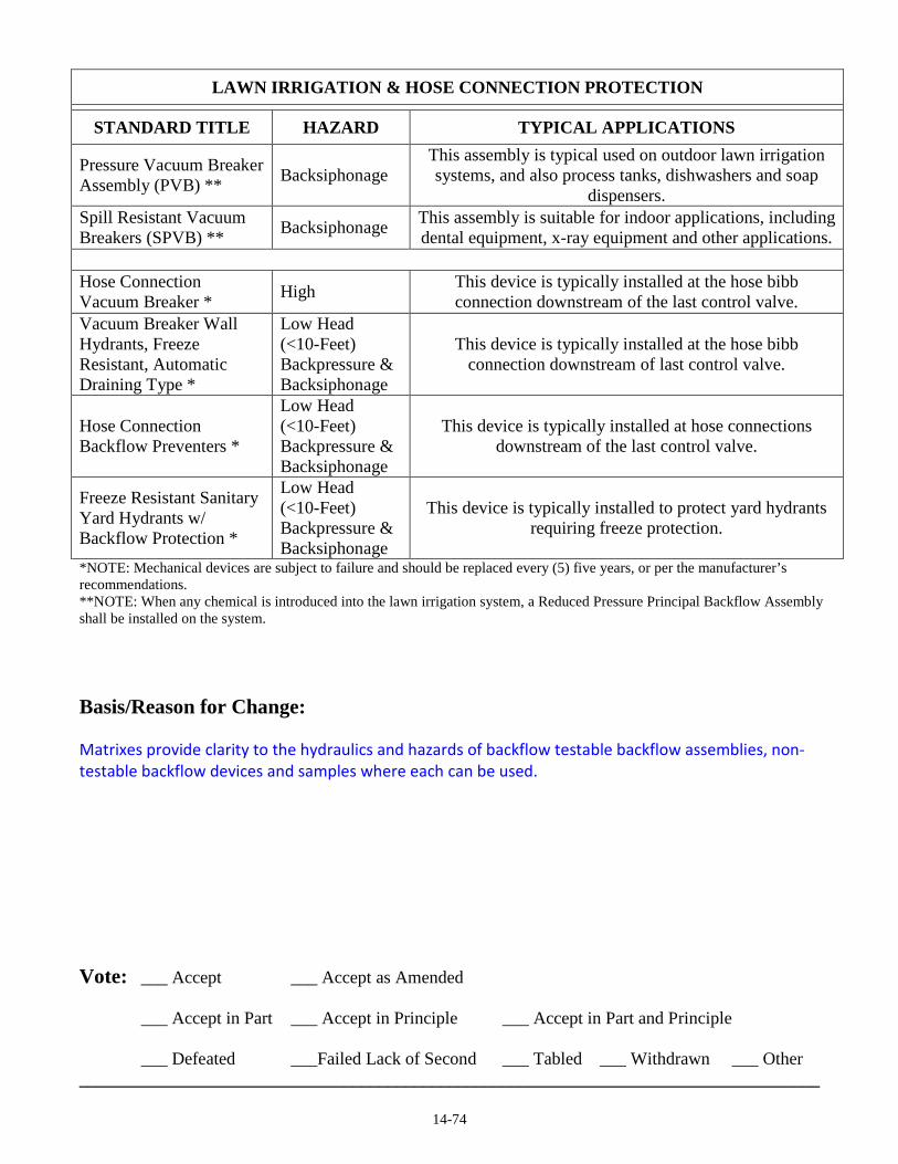
14-74
LAWN IRRIGATION & HOSE CONNECTION PROTECTION
STANDARD TITLE HAZARD TYPICAL APPLICATIONS
Pressure Vacuum Breaker Assembly (PVB) ** Backsiphonage
This assembly is typical used on outdoor lawn irrigation systems, and also process tanks, dishwashers and soap
dispensers. Spill Resistant Vacuum Breakers (SPVB) ** Backsiphonage This assembly is suitable for indoor applications, including
dental equipment, x-ray equipment and other applications.
Hose Connection Vacuum Breaker * High This device is typically installed at the hose bibb
connection downstream of the last control valve. Vacuum Breaker Wall Hydrants, Freeze Resistant, Automatic Draining Type *
Low Head (<10-Feet) Backpressure & Backsiphonage
This device is typically installed at the hose bibb connection downstream of last control valve.
Hose Connection Backflow Preventers *
Low Head (<10-Feet) Backpressure & Backsiphonage
This device is typically installed at hose connections downstream of the last control valve.
Freeze Resistant Sanitary Yard Hydrants w/ Backflow Protection *
Low Head (<10-Feet) Backpressure & Backsiphonage
This device is typically installed to protect yard hydrants requiring freeze protection.
*NOTE: Mechanical devices are subject to failure and should be replaced every (5) five years, or per the manufacturer’s recommendations. **NOTE: When any chemical is introduced into the lawn irrigation system, a Reduced Pressure Principal Backflow Assembly shall be installed on the system. Basis/Reason for Change: Matrixes provide clarity to the hydraulics and hazards of backflow testable backflow assemblies, non-testable backflow devices and samples where each can be used. Vote: ___ Accept ___ Accept as Amended
___ Accept in Part ___ Accept in Principle ___ Accept in Part and Principle
___ Defeated ___Failed Lack of Second ___ Tabled ___ Withdrawn ___ Other ____________________________________________________________________________________

14-75
National Standard Plumbing Code 2015 Proposed Code Change Form
14 - 75
Contact Information: Person Submitting Change NSPC Committee Date 04-07-2014 . Mailing Address 180 S. Washington Street, P.O. Box 6808 . City/State/Zip Falls Church, VA 22046 . Phone 1-800-533-7694 Fax 1-703-237-7442 E-mail [email protected] Check All That Apply: ___ Amend section with this editorial change __X_ Change subsection to read as follows ____ Delete subsection and substitute as follows ____ Add new subsection to read as follows ____ Delete subsection without substitution Code Section: Table 10.8.3 Delete existing Table 10.8.3 in its entirety, including Note 1. Replace it with Table 10.8.3 below:
Table 10.8.3 Size of Overflow Pipes for Water Supply Tanks
Maximum Makeup Water Flow - gpm 13 55 100 165 355 640 1040 >1040 Overflow Pipe Size - inches 1-1/2 2 2-1/2 3 4 5 6 8 Basis/Reason for Change: To delete unnecessary data in Table 10.8.3 Vote: ___ Accept ___ Accept as Amended
___ Accept in Part ___ Accept in Principle ___ Accept in Part and Principle
___ Defeated ___Failed Lack of Second ___ Tabled ___ Withdrawn ___ Other ______________________________________________________________________________

14-76
National Standard Plumbing Code 2015 Proposed Code Change Form
14 - 76
Contact Information: Person Submitting Change NSPC Committee Date 02-09-2014 . Mailing Address 180 S. Washington Street, P.O. Box 6808 . City/State/Zip Falls Church, VA 22046 . Phone 1-800-533-7694 Fax 1-703-237-7442 E-mail [email protected] Check All That Apply: __X _ Amend section with this editorial change ____ Change subsection to read as follows ____ Delete subsection and substitute as follows ____ Add new subsection to read as follows ____ Delete subsection without substitution Code Section: 10.12 WATER SUPPLY CONTROL SHUTOFF VALVES 10.12.9 Valve Accessibilty Water supply control shutoff valves shall be placed so as to be accessible for use, service, and maintenance.
Comment: Access to water supply shutoff valves can require the use of tools to remove access panels or doors.
Basis/Reason for Change: The water supply valves in Section 10.12 are shutoff valves, not control valves. Vote: ___ Accept ___ Accept as Amended
___ Accept in Part ___ Accept in Principle ___ Accept in Part and Principle
___ Defeated ___Failed Lack of Second ___ Tabled ___ Withdrawn ___ Other ______________________________________________________________________________

14-77
National Standard Plumbing Code 2015 Proposed Code Change Form
14 - 77
Contact Information: Person Submitting Change NSPC Committee Date 04-30-2014 . Mailing Address 180 S. Washington Street, P.O. Box 6808 . City/State/Zip Falls Church, VA 22046 . Phone 1-800-533-7694 Fax 1-703-237-7442 E-mail [email protected] Check All That Apply: ___ Amend section with this editorial change __X_ Change subsection to read as follows ____ Delete subsection and substitute as follows ____ Add new subsection to read as follows ____ Delete subsection without substitution Code Section: 10.12 WATER SUPPLY CONTROL SHUTOFF VALVES 10.12.2 Building Valve a. The building water service shall be provided with a readily accessible gate valve with bleed or other full-way shutoff valve with bleed located inside the building near the point where the water service enters. When the building water service enters a crawl space, the building valve shall be readily accessible. Where there are two or more water services serving one building, a check valve shall be installed on each service in addition to the above shutoff valves.
b. Provisions shall be made to drain the piping immediately downstream from the building valve for service or maintenance. Drains shall be capped or plugged to prevent them from being inadvertently discharged.
c. If a building has two or more water services that are interconnected within the building, full-size check valves shall be installed near the outlets of the building valves to prevent backflow from one water service to another. Pressure test connections shall be provided on both sides of the check valves. EXCEPTION: Check valves shall not be required if the water services include backflow prevention for containment of the premises. Basis/Reason for Change: To clarify the requirements for draining the water supply piping at the building valve and preventing backflow between multiple water services that are interconnected within the building. Vote: ___ Accept ___ Accept as Amended
___ Accept in Part ___ Accept in Principle ___ Accept in Part and Principle
___ Defeated ___Failed Lack of Second ___ Tabled ___ Withdrawn ___ Other ______________________________________________________________________________

14-78
National Standard Plumbing Code 2015 Proposed Code Change Form
14 - 78
Contact Information: Person Submitting Change NSPC Committee Date 04-05-2014 . Mailing Address 180 S. Washington Street, P.O. Box 6808 . City/State/Zip Falls Church, VA 22046 . Phone 1-800-533-7694 Fax 1-703-237-7442 E-mail [email protected] Check All That Apply: ___ Amend section with this editorial change __X_ Change subsection to read as follows ____ Delete subsection and substitute as follows ____ Add new subsection to read as follows ____ Delete subsection without substitution Code Section: 10.12 WATER SUPPLY CONTROL SHUTOFF VALVES 10.12.4 Valves in Dwelling Units a. In single dwelling units, the building valve required by Section 10.12.2 shall shutoff the water supply to all fixtures and outlets. b. In multiple dwelling units, one or more shutoff valves shall be provided in the main water supply piping or main branches in each dwelling unit so that the water supply to any plumbing fixture or group of fixtures in for that dwelling unit can be shutoff without stopping the water supply to fixtures in other dwelling units. These valves shall be accessible in the dwelling unit that they control. c. Except as permitted in Section 10.12.4.d in residential powder rooms or half-baths, bathroom groups, and hotel/motel guest rooms, individual fixture shutoff or stop valves shall be provided for water closets, lavatories, kitchen sinks, laundry trays tubs and sinks, bar sinks, bidets, clothes washing machines, sill cocks, wall hydrants, appliances, and equipment connected to the water supply system. Valves for fixtures, appliances, and equipment shall be accessible without having to move the appliance or equipment, except for ice makers. EXCEPTION: Appliances shall be permitted to be moved for access to shutoff valves for ice
makers. d. Unless individual fixture shutoff valves are provided for fixtures in powder rooms or bathroom groups in accordance with Section 10.12.4.c, shutoff valves may be provided for the each powder room or bathroom group in lieu of individual fixture shutoff valves. In individual dwelling units where powder rooms or bathroom groups are located adjacent to each other or one

14-78
directly above the other, they may be considered as a single group and shall be permitted to have a single set of shutoff valves. d. Individual fixture shutoff valves shall not be required in residential powder rooms or half-baths, bathroom groups, and hotel/motel guest rooms if accessible shutoff valves are provided in the water supply piping for those rooms. If a powder room/half-bath and a bathroom group are located adjacent to each other and are supplied by the same water supply piping, one set of accessible shutoff valves shall be permitted to serve both rooms. e. Self-piercing and needle-type saddle valves shall be are prohibited. 10.12.6 Individual Fixture Valves Valves in Other Than Dwelling Units a. In a building used or intended to be used for other than dwelling purposes, the water distribution pipe to each fixture or other piece of equipment shall be provided with a valve or fixture stop to shut off the water to the fixture or to the room in which it is located. These valves shall be accessible. Each sill cock and wall hydrant shall be separately controlled by a valve inside the building. a. In other than dwelling units, accessible shutoff valves or stop valves shall be provided for each plumbing fixture, sill cock, wall hydrant, appliance or equipment connected to the water supply system. b. Self-piercing and needle-type saddle valves shall be are prohibited. Basis/Reason for Change: To clarify the requirements for providing water supply shutoff valves. Vote: ___ Accept ___ Accept as Amended
___ Accept in Part ___ Accept in Principle ___ Accept in Part and Principle
___ Defeated ___Failed Lack of Second ___ Tabled ___ Withdrawn ___ Other ______________________________________________________________________________

14-79
National Standard Plumbing Code 2015 Proposed Code Change Form
14 - 79
Contact Information: Person Submitting Change NSPC Committee Date 02-28-2014 . Mailing Address 180 S. Washington Street, P.O. Box 6808 . City/State/Zip Falls Church, VA 22046 . Phone 1-800-533-7694 Fax 1-703-237-7442 E-mail [email protected] Check All That Apply: ___ Amend section with this editorial change __X_ Change subsection to read as follows ____ Delete subsection and substitute as follows ____ Add new subsection to read as follows ____ Delete subsection without substitution Code Section: 10.13 FLEXIBLE WATER CONNECTORS Flexible water connectors exposed to continuous pressure shall conform to ASME A112.18.6/CSA B125.6. Access shall be provided to all flexible water connectors. Basis/Reason for Change: The 2009 editions of ASME A112.18.6 and CSA B125.6 were combined. Vote: ___ Accept ___ Accept as Amended
___ Accept in Part ___ Accept in Principle ___ Accept in Part and Principle
___ Defeated ___Failed Lack of Second ___ Tabled ___ Withdrawn ___ Other ______________________________________________________________________________

14-80
National Standard Plumbing Code 2015 Proposed Code Change Form
14 - 80
Contact Information: Person Submitting Change NSPC Committee Date 02-09-2014 . Mailing Address 180 S. Washington Street, P.O. Box 6808 . City/State/Zip Falls Church, VA 22046 . Phone 1-800-533-7694 Fax 1-703-237-7442 E-mail [email protected] Check All That Apply: __X_ Amend section with this editorial change ____ Change subsection to read as follows ____ Delete subsection and substitute as follows ____ Add new subsection to read as follows ____ Delete subsection without substitution Code Sections: 10.14.7 and 10.16.7 10.14.7 Water Hammer a. Approved water hammer arresters, complying with ANSI/ASSE 1010 or PDI WH201 ASSE 1010 or PDI WH 201 shall be installed on water distribution piping in which quick closing valves are installed. EXCEPTION: Single lever faucets, domestic clothes washers, and domestic dishwashers. b. Water hammer arresters shall be placed as close as possible to the quick acting valve, at the end of long piping runs, or near batteries of fixtures. c. Arresters shall be accessible for replacement. See Figure 10.14.7 10.16.7 Vacuum Relief Valves for Water Heaters a. Where water distribution piping can siphon water from a water heater and cause dry-firing, a vacuum relief valve shall be installed on the cold water piping to the water heater. b. Vacuum relief valves shall comply with ANSI Z21.22/CSA 4.4 and be rated for not less than 210ºF. c. Valves shall be the full size of the water heater inlet pipe and be installed at an elevation above the top of the heater tank. See Figure 10.16.7 Basis/Reason for Change: To update the designations of the standards that are referenced. Vote: ___ Accept ___ Accept as Amended
___ Accept in Part ___ Accept in Principle ___ Accept in Part and Principle
___ Defeated ___Failed Lack of Second ___ Tabled ___ Withdrawn ___ Other ______________________________________________________________________________

14-81
National Standard Plumbing Code 2015 Proposed Code Change Form
14 - 81
Contact Information: Person Submitting Change NSPC Committee Date 04-30-2014 . Mailing Address 180 S. Washington Street, P.O. Box 6808 . City/State/Zip Falls Church, VA 22046 . Phone 1-800-533-7694 Fax 1-703-237-7442 E-mail [email protected] Check All That Apply: ___ Amend section with this editorial change __X_ Change subsection to read as follows ____ Delete subsection and substitute as follows ____ Add new subsection to read as follows ____ Delete subsection without substitution Code Section: 10.15.1 Hot Water Supply System In residences and buildings intended for human occupancy, hot water shall be supplied to all plumbing fixtures, appliances, and equipment used for bathing, washing, culinary purposes, cleansing, laundry or building maintenance that require hot water for their use. EXCEPTION: In buildings other than dwelling units, tempered water supply systems shall be permitted to supply fixtures that deliver only tempered water. 1.2 Hot Water: Potable water that is heated to a required temperature for its intended use for domestic use including bathing, washing, dishwashing, clothes washing, cleaning, and maintenance. Basis/Reason for Change: To clarify that the requirements of Section 10.15 are for domestic hot water. The requirements in Section 10.15.1 are for supplying hot water, not for the hot water supply system. Tempered water is permitted for gang showers in Section 10.15.6. Vote: ___ Accept ___ Accept as Amended
___ Accept in Part ___ Accept in Principle ___ Accept in Part and Principle
___ Defeated ___Failed Lack of Second ___ Tabled ___ Withdrawn ___ Other ______________________________________________________________________________

14-82
National Standard Plumbing Code 2015 Proposed Code Change Form
14 - 82
Contact Information: Person Submitting Change NSPC Committee Date 3-07-2014 . Mailing Address 180 S. Washington Street, P.O. Box 6808 . City/State/Zip Falls Church, VA 22046 . Phone 1-800-533-7694 Fax 1-703-237-7442 E-mail [email protected] Check All That Apply: ___ Amend section with this editorial change __X_ Change subsection to read as follows ____ Delete subsection and substitute as follows ____ Add new subsection to read as follows ____ Delete subsection without substitution Code Section: 10.15.2 Temperature Maintenance Where Required a. Heated water distribution systems in buildings where the developed length of the heated water piping from the source of the heated water to the farthest fixture exceeds 100 feet shall maintain heated water temperature in all supply piping to within 25 feet of any heated water outlet. b. An approved electric heat tracing system shall be permitted to be used to satisfy the requirements of Section 10.15.2a. c. An on-demand recirculation system, actuated by sensors or manually operated buttons, shall be permitted to be used to satify the requirements of Section 10.15.2.a. a. Where the developed length of the hot water supply piping exceeds 100 feet from the hot water source to the farthest hot water outlet, the system shall maintain the temperature of the hot water to within 25 feet developed length from every hot water outlet served. b. Where required by Section 10.15.2a, the hot water temperature within the piping shall be maintained by heat tracing or recirculation of the hot water. The temperature of the hot water in the piping shall be maintained by automatic controls with manual auto-off. c. The requirements of this section for temperature maintenance also apply to tempered water supply piping. Basis/Reason for Change: To clarify the requirements for hot water temperature maintenance. Vote: ___ Accept ___ Accept as Amended
___ Accept in Part ___ Accept in Principle ___ Accept in Part and Principle
___ Defeated ___Failed Lack of Second ___ Tabled ___ Withdrawn ___ Other ______________________________________________________________________________

National Standard Plumbing Code 2015 Proposed Code Change Form Deadline April 30, 2014
14 - 83
14-83
Contact Information: Person Submitting Change 2 ______Greg Towsley______________ Date 3 ___3/13/2014_____ Jurisdiction/Company/ Mailing Address _____ GRUNDFOS 17100 W. 118th Terrace __________________ City/State/Zip ____ Olathe, KS 66061 _________________ Phone _____913 227 3414___ Fax ___559 346 6414___ [email protected]_______ IMPORTANT: Please review the attached instruction sheet regarding proposed code changes. Check All That Apply: _____ Amend section with this editorial change _____ Change subsection to read as follows _____ Delete subsection and substitute as follows _____ Add new subsection to read as follows _____ Delete subsection without substitution Code Section: __ Section 10.15.2.c____________ 10.15.2c. - An on-demand recirculation A recirculation system, activated by sensors or manually operated buttons, shall be permitted to be used to satisfy the requirements of Section 10.15.2a. Basis/Reason for Change: This proposed modification would allow the intent of the operating the hot water pump in the recirculation system with sensors or manual operation, but not specifically requiring an “on-demand” system from the only manufacturer with that trademark or patent. Vote: ___ Accept ___ Accept as Amended
___ Accept in Part ___ Accept in Principle ___ Accept in Part and Principle
___ Defeated ___Failed Lack of Second ___ Tabled ___ Withdrawn ___ Other ____________________________________________________________________________________

14-84
National Standard Plumbing Code 2015 Proposed Code Change Form
14 - 84
Contact Information: Person Submitting Change NSPC Committee Date 4-30-2014 . Mailing Address 180 S. Washington Street, P.O. Box 6808 . City/State/Zip Falls Church, VA 22046 . Phone 1-800-533-7694 Fax 1-703-237-7442 E-mail [email protected] Check All That Apply: ___ Amend section with this editorial change __X_ Change subsection to read as follows ____ Delete subsection and substitute as follows ____ Add new subsection to read as follows ____ Delete subsection without substitution Code Section: 10.15.6 Mixed Water Temperature Control l. a. Hot Water Supply Sources: The temperature control devices for water heaters and other hot water supply sources shall not be permitted to be used to meet this Section's requirements for mixed water temperature control. f. Temperature Actuated Mixing Valves: b. Hot Water Distribution Temperature Control: Where temperature-actuated mixing valves are installed to control the in-line hot water supply temperature in the water distribution system, they shall comply with ASSE 1017. Such devices shall be installed at the hot water source and alone shall not supersede the other requirements of Section 10.15.6 for mixed water temperature control. c. Application of Water Temperature Control and Limiting Devices: The inlet hot and cold water temperatures for temperature control and limiting devices shall be within their operating ranges and have sufficient differential above and below their discharge set point. k. d. Where Check Valves Are Required: Where a mixed water temperature control or temperature limiting device supplies one or more outlets that can be shutoff downstream from the control device, the control device shall include integral check valves or check valves shall be provided in the hot and cold water supplies to the control device or at its inlets to prevent cross flow through the device when there is no flow through the outlet or outlets that it supplies.
EXCEPTION: In one-and two-family dwellings, check valves shall not be required for an ASSE 1017 device installed at the water heater and directly connected to its hot and cold water piping.
a e. Showers and Bath/Shower Combinations: All showers and bath/shower combinations shall be provided with individual balanced pressure, thermostatic, or combination automatic compensating valves that comply with ASME A112.1016/ASSE 1016/CSA B125.16 or ASME A112.18.1/CSA B125.1. The automatic compensating valves shall control the water temperature to wall or ceiling-mounted hand-held showers, shower heads, body sprays either in individual shower or tub/shower combination fittings, and tub spouts when part of tub/shower combination fittings. These valves shall include a means to limit the maximum discharge temperature of the

14-84
water and shall be installed and field-adjusted in accordance with the manufacturer's instructions to a temperature no higher than 120°F. No further mixing of water shall be permitted downstream of the automatic compensating valve. The water discharged from shower heads, wall or ceiling mounted hand held showers, body sprays, and tub spouts shall be controlled to a temperature no higher than 120ºF by a Type P, Type T or Type P/T automatic compensating valve complying with ASME A112.1016/ASSE 1016/CSA B125.16. EXCEPTION: Where multiple showers are supplied by a one-pipe tempered water distribution system, the tempered water distribution system shall be controlled by an automatic temperature control mixing valve complying with ASSE 1069. These valves shall include a means to limit the maximum discharge temperature of the water and shall be installed and field-adjusted in accordance with the manufacturer's instructions to a temperature no higher than 105°F. No further mixing of water shall be permitted downstream of the automatic temperature control mixing valve. f. Multiple Showers: Where multiple (gang) showers are supplied by a one pipe tempered water supply system, the water temperature shall be controlled to a temperature no higher than 105ºF by an automatic temperature control mixing valve complying with ASSE 1069. g. Multiple Lavatories: Where multiple lavatories are supplied by a one-pipe tempered water supply system, the water temperature shall be controlled to a temperature no higher than 110ºF by a water temperature limiting device complying with ASSE 1070 or CSA B125.3. b. h. Bathtubs and Whirlpool Baths: The water discharged into hot water supply to the faucets for bathtubs and whirlpool baths without showers and with or without deck-mounted hand sprays, shall be controlled to a temperature no higher than 120°F by a water temperature limiting device complying with ASSE 1070 or CSA B125.3 or ASSE 1016. c. i. Bidets: The hot water supply to the faucet on bidet plumbing fixtures shall be limited to controlled to a temperature no higher than 110°F by a water temperature limiting device complying with ASSE 1070 or CSA B125.3. Where bidets are incorporated into toilet seats or consist of a heated water tank and nozzle, their controls shall limit the discharge temperature to no more than 110°F. d. j. Public-Use Hand Washing Facilities: Water discharged from public-use The hot water supply to the controls for hand washing facilities in public toilet rooms, hotel and motel guest rooms, and hospital patient rooms shall be limited controlled to a temperature no higher than 110°F. Water temperature limiting devices serving one or more fixtures and thermostatic faucets shall comply with ASSE 1070 by a water temperature limiting device complying with ASSE 1070 or CSA B125.3. Control valves controlling Devices serving more than one fixture shall be sized for the required total water flow. o. k. Medical and Clinical Use Hand Washing Facilities: The hot water supply to the faucets for medical and clinical hand washing facilities shall be limited to a temperature no higher than 110°F by a water temperature limiting device complying with ASSE 1070 or CSA B125.3. e. l. Commercial Hair/Shampoo Sink Sprays: The temperature of water from hot water supply to the faucets and controls for commercial hair/shampoo sink sprays and pedicure basins

14-84
shall be limited to a temperature no higher than 110°F by a temperature limiting device complying with ASSE 1070, ASME A112.18.1/CSA B125.1, or CSA B125.3. n. m. Animal Washing Fixtures: The hot water discharge into supply to the faucet or control device for an animal washing fixture shall be controlled to a temperature no higher than 110°F by a temperature limiting device complying with ASSE 1070 or CSA B125.3. g. Automatic temperature control mixing valves that supply gang showers shall comply with ASSE 1069. h. Where ASSE 1070 water temperature limiting devices are required, they shall be point-of-use for a single fixture or used for distribution to multiple fixtures having the same maximum water temperature requirement, depending on the maximum flow rate of the device. EXCEPTION: ASSE 1070 devices shall not be used for gang showers. i. n. Temperature Actuated Flow Reduction (TAFR) Devices: Where temperature actuated flow reduction (TAFR) devices are installed to limit the maximum discharge mixed water temperature to 120°F for individual fixture fittings, such devices shall comply with ASSE 1062. These devices shall not supersede the other requirements of Section 10.15.6. j. o. In-Line Pressure Balancing Valves: Where in-line pressure balancing valves are installed to compensate for water pressure fluctuations to stabilize the temperature discharges from their individual faucet or fixture fitting, such devices shall comply with ASSE 1066. These devices shall be installed in an accessible location and alone shall not supersede the other requirements of Section 10.15.6. p. Devices installed for mixed water temperature control, temperature limiting, flow reduction, or pressure balance shall be field-adjusted in accordance with the manufacturer’s instructions. m. Alternate Methods: The use of combination water temperature control or limiting devices that comply with the standards listed in Table 3.1.3 and satisfy the performance requirements of Section 10.15.6 shall be subject to the approval of the Authority Having Jurisdiction. Basis/Reason for Change: Includes changes 13-174 and 13-176 as approved and published in the 2013 Supplement. The requirements for medical and clinical use hand washing facilities are based on 13-179 which was tabled. The proposed changes for 2015 are indicated, including reorganization. Vote: ___ Accept ___ Accept as Amended
___ Accept in Part ___ Accept in Principle ___ Accept in Part and Principle
___ Defeated ___Failed Lack of Second ___ Tabled ___ Withdrawn ___ Other ______________________________________________________________________________

14-85
National Standard Plumbing Code 2015 Proposed Code Change Form _____________________________________________________________
14 - 85
Contact Information: Person Submitting Change NSPC Committee Date 04-29-2014 . Mailing Address 180 S. Washington Street, P.O. Box 6808 . City/State/Zip Falls Church, VA 22046 . Phone 1-800-533-7694 Fax 1-703-237-7442 E-mail [email protected] Check All That Apply: ___ Amend section with this editorial change __X_ Change subsection to read as follows ____ Delete subsection and substitute as follows ____ Add new subsection to read as follows ____ Delete subsection without substitution Code Section: 10.15.6 Mixed Water Temperature Control
j. Hand Washing Facilities: The hot water supply to the following hand washing fixtures shall be controlled to a temperature no higher than 110ºF by a water temperature limiting device complying with ASSE 1070 or CSA B125.3:
1. in public toilet rooms 2. in hotel and motel guest rooms 3. in hospital patient rooms 4. in medical and clinical treatment rooms 5. wash fountains 6. wash sinks j. Public-Use Hand Washing Facilities: The hot water supply to the controls for hand washing facilities in public toilet rooms, hotel and motel guest rooms, and hospital patient rooms shall be controlled to a temperature no higher than 110°F by a water temperature limiting device complying with ASSE 1070 or CSA B125.3. Devices serving more than one fixture shall be sized for the required total water flow. k. Medical and Clinical Use Hand Washing Facilities: The hot water supply to the faucets for medical and clinical hand washing facilities shall be limited to a temperature no higher than 110°F by a water temperature limiting device complying with ASSE 1070 or CSA B125.3. Basis/Reason for Change: To combine all of the hot water temperature control requirements for hand washing in one part of Section 10.15.6. Vote: ___ Accept ___ Accept as Amended
___ Accept in Part ___ Accept in Principle ___ Accept in Part and Principle
___ Defeated ___Failed Lack of Second ___ Tabled ___ Withdrawn ___ Other ______________________________________________________________________________

14-86
National Standard Plumbing Code 2015 Proposed Code Change Form
14 - 86
Contact Information: Person Submitting Change NSPC Committee Date 04-29-2014 . Mailing Address 180 S. Washington Street, P.O. Box 6808 . City/State/Zip Falls Church, VA 22046 . Phone 1-800-533-7694 Fax 1-703-237-7442 E-mail [email protected] Check All That Apply: ___ Amend section with this editorial change __X_ Change subsection to read as follows ____ Delete subsection and substitute as follows ____ Add new subsection to read as follows ____ Delete subsection without substitution Code Section: 10.15 HOT WATER 10.15.7 Thermal Expansion Control a. Where a water pressure regulator (with or without an internal thermal expansion bypass), a backflow prevention device, or a check valve is installed in the supply to water heating equipment such that a closed system is created to the water supply source for the hot water heating equipment, a device for controlling thermal expansion shall be provided. EXCEPTIONS: (1) Instantaneous water heaters. (2) Well systems with water pressure tanks. b. Thermal expansion tanks shall be the adjustable pre-charged type for potable water, steel construction with a flexible bladder or bellows, rated for not less than 125 psig and 200ºF, and sized to limit the increased water system pressure to no higher than 100 psig. Tanks shall be sized and installed in accordance with the manufacturer’s instructions. c. Thermal expansion relief valves shall be permitted if approved by the Authority Having Jurisdiction. Relief valves shall maintain no higher than 100 psig water system pressure. The discharge from the relief valves shall be piped to an indirect waste receptor. d. Thermal expansion control devices shall be connected to the water supply piping between the hot water heating equipment and its shutoff valve. Appendix F.2 References: 10.15.7.c Thermal expansion relief valves Basis/Reason for Change: To clarify the requirements for thermal expansion control for water heaters. Vote: ___ Accept ___ Accept as Amended
___ Accept in Part ___ Accept in Principle ___ Accept in Part and Principle
___ Defeated ___Failed Lack of Second ___ Tabled ___ Withdrawn ___ Other ______________________________________________________________________________

National Standard Plumbing Code 2015 Proposed Code Change Form Deadline April 30, 2014
14 - 87
14-87
Contact Information: Person Submitting Change 2 _____ Michael G. Baker____________ Date 3 ___March 12, 2014___ Jurisdiction/Company/ Mailing Address __President, New Jersey Plumbing Inspectors Association _______________ City/State/Zip __475 Valley Rd. Wayne, NJ 07470______________________________ Phone __973.694.1800x3287 Fax __973.709.0209 E-mail ____ [email protected] IMPORTANT: Please review the attached instruction sheet regarding proposed code changes. Check All That Apply: _____ Amend section with this editorial change _____ Change subsection to read as follows _____ Delete subsection and substitute as follows _XX Add new subsection to read as follows _____ Delete subsection without substitution Code Section: 10.15.9.3 Drainage c. Water Heaters without legs shall be required to be raised as to not diminish the capacity of the pan Basis/Reason for Change: The placement of water heaters directly in a pan severely limits its capacity Vote: ___ Accept ___ Accept as Amended
___ Accept in Part ___ Accept in Principle ___ Accept in Part and Principle
___ Defeated ___Failed Lack of Second ___ Tabled ___ Withdrawn ___ Other ____________________________________________________________________________________

14-88
National Standard Plumbing Code 2015 Proposed Code Change Form
14 - 88
Contact Information: Person Submitting Change NSPC Committee Date 04-29-2014 . Mailing Address 180 S. Washington Street, P.O. Box 6808 . City/State/Zip Falls Church, VA 22046 . Phone 1-800-533-7694 Fax 1-703-237-7442 E-mail [email protected] Check All That Apply: ___ Amend section with this editorial change ____ Change subsection to read as follows ____ Delete subsection and substitute as follows ____ Add new subsection to read as follows ____ Delete subsection without substitution Code Section: 10.15.11 and 10.16.5 10.15.11 Tankless (Instantanious) Water Heaters Hot Water Heaters Tankless water heaters, including whole-home, multi-fixture, and point-of-use heaters, a. Hot water heaters shall be applied, sized, and installed in accordance with the manufacturer’s recommendations and instructions. b. Gas-fired storage tank water heaters with input ratings of 75,000 Btuh or less shall comply with ANSI Z21.10.1/CSA 4.1. c. Gas-fired storage tank water heaters with input ratings above 75,000 Btuh shall comply with ANSI Z21.10.3/CSA 4.3. d. Gas-fired tankless water heaters shall comply with ANSI Z21.10.3/CSA 4.3. e. Oil-fired storage tank water heaters shall comply with UL 732. f. Household electric storage tank waters heaters up to 120 gallons and 12 KW capacity shall comply with UL 174. g. Commercial electric storage tank water heaters over 120 gallons and 12 KW capacity shall comply with UL 1453. h. Tankless electric water heaters shall comply with UL 499. Comment: Tankless water heaters include whole-home, multi-fixture, and point-of-use heaters. 10.16.5 Tankless Water Heaters a. Tankless instantaneous water heaters shall have an overheat prevention device to shutoff the unit in the event of unsafe high water temperature. The pressure and temperature tank protection required by Section 10.16.1 shall not be necessary unless required by the manufacturer’s installation instructions. b. The outlet temperature control device for tankless water heaters shall be set no higher than 140ºF hot water. c. Gas-fired tankless water heaters shall comply with the safety requirements of ANSI Z21.10.3/CSA 4.3. d. Electric tankless point-of-use water heaters shall comply with UL 499.

14-88
Basis/Reason for Change: To list the requirements for hot water heaters in Section 10.15 HOT WATER. Section 10.16 is for safety devices for pressure vessels. Vote: ___ Accept ___ Accept as Amended
___ Accept in Part ___ Accept in Principle ___ Accept in Part and Principle
___ Defeated ___Failed Lack of Second ___ Tabled ___ Withdrawn ___ Other ______________________________________________________________________________

14-89
National Standard Plumbing Code 2015 Proposed Code Change Form
14 - 89
Contact Information: Person Submitting Change NSPC Committee Date 04-29-2014 Mailing Address 180 S. Washington Street, P.O. Box 6808 . City/State/Zip Falls Church, VA 22046 . Phone 1-800-533-7694 Fax 1-703-237-7442 E-mail [email protected] Check All That Apply: ___ Amend section with this editorial change __X_ Change subsection to read as follows ____ Delete subsection and substitute as follows ____ Add new subsection to read as follows ____ Delete subsection without substitution Code Section: 10.16 SAFETY DEVICES FOR PRESSURE VESSELS 10.16.3 Temperature Relief Valves a. Temperature relief valves shall be of have an adequate relief rating, expressed in BTU/HR, for the equipment served. b. The CSA temperature steam rating shall be used when a water heater has a heat input rating of 200,000 BTU/HR or less, a water temperature of 210ºF or less, a nominal water-containing capacity of 120 gallons or less, is not ASME rated, and does not exhibit an ASME “HWL” symbol or a National Board “NB” number. c. The ASME pressure steam rating shall be used if a water heater is ASME rated, and exhibits an ASME “HWL” symbol or a National Board “NB” number. b. d. The valves shall be installed so that the temperature sensing element is in the hottest water within the top 6 inches of the tank. c. e. The valves shall be set to open when the stored water temperature reaches a maximum of 210ºF. (See Section 3.3.10.) d. f. The valves shall conform to an approved standard and shall be sized so that when the valve opens, the water temperature cannot exceed 210ºF with the water heating equipment operating at maximum input. See Figure 10.16.6 Basis/Reason for Change: To clarify the requirements for sizing temperature relief valves and combination P&T relief valves for water heaters and storage tanks. Vote: ___ Accept ___ Accept as Amended
___ Accept in Part ___ Accept in Principle ___ Accept in Part and Principle
___ Defeated ___Failed Lack of Second ___ Tabled ___ Withdrawn ___ Other ______________________________________________________________________________

National Standard Plumbing Code 2015 Proposed Code Change Form Deadline April 30, 2014
14 - 90
14-90
Contact Information: Person Submitting Change 2 Donald M. Jones Date 3 April 23, 2014 Jurisdiction/Company/ Mailing Address 202 W. Summit St. City/State/Zip Vineland, NJ 08360 Phone (609)517-1473 Fax __________________ E-mail [email protected] IMPORTANT: Please review the attached instruction sheet regarding proposed code changes. Check All That Apply: _____ Amend section with this editorial change X Change subsection to read as follows _____ Delete subsection and substitute as follows _____ Add new subsection to read as follows _____ Delete subsection without substitution Code Section: NSPC 10.16.3 THE FOLLOWING AMENDMENT IS SUBMITTED: NSPC Section 10.16.3
10.16.3 Temperature Relief Valve
a. Temperature relief valves shall be of adequate relief rating according to their CSA temperature steam rating, expressed in BTU/HR, for the equipment served.
EXCEPTION: ASME/NB (National Board of Boiler and Pressure Vessel Inspectors) BTU/HR capacity ratings may be used for ASME vessels only b. The valves shall be installed so that the temperature sensing element is immersed in the hottest water within the top 6 inches of the tank.
c. The valves shall be set to open when the stored water temperature reaches a maximum of 210°F. (See Section 3.3.10)
d. The valves shall conform to an approved standard and shall be sized so that when the valve opens, the water temperature cannot exceed 210°F with the water heating equipment operating at maximum input
Basis/Reason for Change: CSA temperature steam ratings are based on a vessel that has 15 psig of accumulated steam pressure. This standard is more restrictive than the ASME/NB rating, which is based on over 150 psig of steam pressure, so the ASME/NB rating will always be higher than the CSA rating. ASME vessels are

14-90
designed and built to a higher standard than ANSI Z21 vessels; therefore, the ASME/NB valve ratings should be limited ASME vessels. The use of the valve’s ASME/NB discharge capacity rating on a non-ASME vessel represents a potentially very unsafe condition. Vote: ___ Accept ___ Accept as Amended
___ Accept in Part ___ Accept in Principle ___ Accept in Part and Principle
___ Defeated ___Failed Lack of Second ___ Tabled ___ Withdrawn ___ Other ____________________________________________________________________________________

14-91
National Standard Plumbing Code 2015 Proposed Code Change Form
14 - 91
Contact Information: Person Submitting Change NSPC Committee Date 04-29-2014 Mailing Address 180 S. Washington Street, P.O. Box 6808 . City/State/Zip Falls Church, VA 22046 . Phone 1-800-533-7694 Fax 1-703-237-7442 E-mail [email protected] Check All That Apply: ___ Amend section with this editorial change __X_ Change subsection to read as follows ____ Delete subsection and substitute as follows ____ Add new subsection to read as follows ____ Delete subsection without substitution Code Section: 10.16.6 Relief Valve Discharge Piping c. The discharge end of the pipe shall be no smaller than the outlet size of its relief valve and shall extend to a point of disposal without valves, traps or rises that would prevent the discharge piping from draining by gravity. The discharge end of the pipe shall not be threaded and shall be cut on an angle of approximately 45 degrees. Basis/Reason for Change: To clarify the required size of relief valve discharge pipes and require that their discharge end be cut to prevent the installation of a push-on type pipe cap. Vote: ___ Accept ___ Accept as Amended
___ Accept in Part ___ Accept in Principle ___ Accept in Part and Principle
___ Defeated ___Failed Lack of Second ___ Tabled ___ Withdrawn ___ Other ______________________________________________________________________________
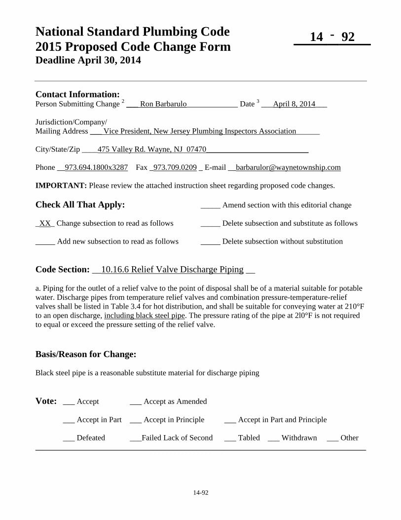
National Standard Plumbing Code 2015 Proposed Code Change Form Deadline April 30, 2014
14 - 92
14-92
Contact Information: Person Submitting Change 2 ___ Ron Barbarulo_____________ Date 3 ___April 8, 2014___ Jurisdiction/Company/ Mailing Address ___ Vice President, New Jersey Plumbing Inspectors Association______ City/State/Zip ____475 Valley Rd. Wayne, NJ 07470__________________________ Phone __973.694.1800x3287 Fax _973.709.0209 _ E-mail [email protected] IMPORTANT: Please review the attached instruction sheet regarding proposed code changes. Check All That Apply: _____ Amend section with this editorial change _XX_ Change subsection to read as follows _____ Delete subsection and substitute as follows _____ Add new subsection to read as follows _____ Delete subsection without substitution Code Section: __10.16.6 Relief Valve Discharge Piping __ a. Piping for the outlet of a relief valve to the point of disposal shall be of a material suitable for potable water. Discharge pipes from temperature relief valves and combination pressure-temperature-relief valves shall be listed in Table 3.4 for hot distribution, and shall be suitable for conveying water at 210°F to an open discharge, including black steel pipe. The pressure rating of the pipe at 2l0°F is not required to equal or exceed the pressure setting of the relief valve. Basis/Reason for Change: Black steel pipe is a reasonable substitute material for discharge piping Vote: ___ Accept ___ Accept as Amended
___ Accept in Part ___ Accept in Principle ___ Accept in Part and Principle
___ Defeated ___Failed Lack of Second ___ Tabled ___ Withdrawn ___ Other ____________________________________________________________________________________

14-93
National Standard Plumbing Code 2015 Proposed Code Change Form
14 - 93
Contact Information: Person Submitting Change NSPC Committee Date 3-07-2014 . Mailing Address 180 S. Washington Street, P.O. Box 6808 . City/State/Zip Falls Church, VA 22046 . Phone 1-800-533-7694 Fax 1-703-237-7442 E-mail [email protected] Check All That Apply: ___ Amend section with this editorial change __X_ Change subsection to read as follows ____ Delete subsection and substitute as follows ____ Add new subsection to read as follows ____ Delete subsection without substitution Code Section: 10.20 NFPA 13D MULTIPURPOSE RESIDENTIAL FIRE SPRINKLER SYSTEMS 10.20.8 Installer Qualifications Installers of NFPA 13D multipurpose residential fire sprinkler systems and individuals who provide layouts, details, and calculations shall be certified to ASSE 7010 if required by the Authority Having Jurisdiction. Table 19.1 REFERENCED STANDARDS ASSE/IAPMO/ANSI 7010 - 2013: Residential Potable Water Fire Protection System Installers for One and Two Family Dwellings ……………………………………………………….10.20.8 Appendix F Requirements of the Adopting Agency 10.20.8 NFPA 13D Installer Qualifications Basis/Reason for Change: To require ASSE 7010 certification for intallers of NFPA 13D multipurpose piping systems if required by the AHJ. Vote: ___ Accept ___ Accept as Amended
___ Accept in Part ___ Accept in Principle ___ Accept in Part and Principle
___ Defeated ___Failed Lack of Second ___ Tabled ___ Withdrawn ___ Other ______________________________________________________________________________

14-94
National Standard Plumbing Code 2015 Proposed Code Change Form
14 - 94
Contact Information: Person Submitting Change NSPC Committee Date 04-29-2014 . Mailing Address 180 S. Washington Street, P.O. Box 6808 . City/State/Zip Falls Church, VA 22046 . Phone 1-800-533-7694 Fax 1-703-237-7442 E-mail [email protected] Check All That Apply: ___ Amend section with this editorial change __X_ Change subsection to read as follows ____ Delete subsection and substitute as follows ____ Add new subsection to read as follows ____ Delete subsection without substitution Code Section: 11.4 FIXTURE UNITS Table 11.4.1 DRAINAGE FIXTURE UNIT (DFU) VALUES DFU DFU DFU DFU (a) (b) (c) (d) Lavatory, 1-1/4” waste 1 1 1 1 2 Lavatory, 1-1/2” waste 2 2 2 X Shower Stall, 1-1/2” trap, up to 2.5 gpm 2 2 2 X Shower Stall, 2” trap 2 2 2 X Showers, Group, per head (Continuous Use) X X 5 X Shower Stall, 2” trap, up to 10 gpm (7) 6 6 6 X Shower Stall, 3” trap, up to 20 gpm (7) 20 20 20 X Unlisted Fixture with Intermittent Use Trap Size, 1-1/4” (Other) 1-1/4” Drain 1 1 1 X Trap Size, 1-1/2” (Other) 1-1/2” Drain 2 2 2 X Trap Size, 2” (Other) 2” Drain 3 3 3 X Trap Size, 3” (Other) 3” Drain 5 5 5 X Trap Size, 4” (Other) 4” Drain 6 6 6 X Unlisted Drain with Extended Discharge (8) 1-1/2” Drain, up to 5 gpm (7) 3 3 3 X 2” Drain, up to 10 gpm (7) 6 6 6 X 3” Drain, up to 20 gpm (7) 20 20 20 X 4” Drain, up to 50 gpm (7) X X 160 X The DFU columns are (a) Individual Dwelling Units (b) Serving 3 or More Dwelling Units (c) Other than Dwelling Units (d) Heavy-Use Assembly

14-94
NOTES FOR TABLE 11.4.1 7. Where other than water-supplied fixtures discharge into the drainage system, allow 2 DFU
for each gallon per minujte (gpm) of flow. (See Section 11.4.2) Refer to Table 11.4.2 for DFUs if the GPM is less than shown. 8. Extended discharge is uninterrupted discharge extending for more than one (1) minute. 11.4.1 Load on Drainage Piping The load on drainage piping shall be computed in drainage fixture units (DFUs) in accordance with Table 11.4.1 and Sections 11.4.2, 11.4.3, and 11.4.4. 11.4.2 Conversion of Flow in GPM to DFU Where the discharge rate of fixtures or equipment is expressed in gallons per minute (GPM), two (2) drainage fixture units (DFU) shall be allowed for each gallon per minute (GPM) of flow. a. Where the drainage from a fixture, appliance, or connected equipment is indicated as discharge flow rate in gallons per minute (GPM), it shall be converted to drainage fixtures units (DFU) in accordance with Table 11.4.2. Interpolation between the listed GPMs is permitted. b. Where discharge flow rates exceed 50 GPM in Table 11.4.2, the associated DFU value shall be determined based on three (3) DFU per GPM. 11.4.3 Diversity Factors (no changes)
Table 11.4.2 FLOW (GPM) TO DRAINAGE FIXTURE UNIT (DFU)
GPM DFU GPM DFU 2.5 2 20 20 4 3 25 43 6 4 30 66 8 5 35 90 10 6 40 112 13 10 45 135 16 15 50 160

14-94
Table 5.2 MINIMUM SIZE OF NON-INTEGRAL TRAPS
Plumbing Fixture Trap Size in Inches Shower stall or shower drain (single shower head) ………………………….1-1/2 Shower stall or shower drain (multiple shower heads)……………………….. 2 Shower stall or enclosure (up to 2.5 GPM) ………………….…………… 1-1/2 Shower stall or enclosure (up to 10 GPM) …………………....…………….. 2 Shower stall or enclosure (up to 20 GPM) …………………..………..…….. 3 Basis for the Change: The DFUs for 1-1/4” lavatories is increased from “1” to”2” for Heavy-Use Assembly based on the increased DFUs for urinals and water closets in that occupancy. DFUs are listed for 1-1/2” lavatories which are required in Table 5.2. The DFU listings based on trap size do not apply to the various fixtures and appliances that are listed in Table 11.4.1. They apply to “unlisted fixtures”, which may not have traps if they are drained indirectly. The proposed changes in Table 11.4.1 related to GPM are based on the maximum GPMs for sloping drains in Table K-2 and the maximum DFUs for horizontal fixture branches in Table 11.5.1B. The maximum GPMs shown for the drain sizes in Table 11.4.1 are based on the drains flowing half-full at their minimum slope as indicated in Table K-2. The DFU values listed are the maximum that can be connected to a horizontal fixture branch in Table 11.5.1B for the pipe sizes shown. The DFUs listed will fully load the drain pipe sizes at half-full. The DFUs for GPMs less than the maximums shown in Table 11.4.1 are listed in Table 11.4.2. The conversion of GPM to DFU above 50 GPM is increased from 2 DFU to 3 DFU per GPM based on the development of Table 11.4.2. The shower trap sizes in Table 5.2 are changed to agree with the trap sizes in Table 11.4.1. Vote: ___ Accept ___ Accept as Amended
___ Accept in Part ___ Accept in Principle ___ Accept in Part and Principle
___ Defeated ___Failed Lack of Second ___ Tabled ___ Withdrawn ___ Other ______________________________________________________________________________

14-95
National Standard Plumbing Code 2015 Proposed Code Change Form
14 - 95
Contact Information: Person Submitting Change NSPC Committee Date 04-29-2014 . Mailing Address 180 S. Washington Street, P.O. Box 6808 . City/State/Zip Falls Church, VA 22046 . Phone 1-800-533-7694 Fax 1-703-237-7442 E-mail [email protected] Check All That Apply: ___ Amend section with this editorial change __X_ Change subsection to read as follows ____ Delete subsection and substitute as follows ____ Add new subsection to read as follows ____ Delete subsection without substitution Code Section: 11.4 FIXTURE UNITS 11.4.4 Floor Drains a. Floor drains shall be sized in accordance with this Section. The minimum size for floor drains is 2” pipe size. b. Floor drains that handle indirect waste shall be sized based on the total drainage fixture units (DFU) that they receive. c. Where floor drains receive a predicable flow in gallons per minute (GPM), they shall be sized according to Table 11.4.1 as an unlisted drain with extended discharge. Their drainage fixture unit (DFU) load shall be based on Table 11.4.2. d. Where floor drains are general purpose, their drainage fixture unit (DFU) load shall be based on their installed drain pipe size as indicated for an unlisted fixture in Table 11.4.1. e. Floor drains associated with emergency fixtures in Section 7.24 shall be sized for the GPM discharge capacity of the emergency fixtures, but the drainage fixture unit (DFU) load on the sanitary drainage system shall be zero (0.0 DFU). The discharge pipe size for such floor drains shall be the minimum size for all downstream drain piping.

14-95
Table 5.2 MINIMUM SIZE OF NON-INTEGRAL TRAPS
Floor Drain (2)……………………………….2, 3, 4, 5, 6 NOTES FOR TABLE 5.2 (2) Refer to Section 11.4.4 for the required size of floor drains.
Table 11.4.1 DRAINAGE FIXTURE UNIT (DFU) VALUES
Floor Drain, Auxiliary………………………. 0 DFU 1.2 Auxiliary Floor Drain, General Purpose: A floor drain that does not receive the discharge from any indirect waste pipe pipes or other predictable drainage flows. Auxiliary floor drains have no DFU loading. Basis/Reason for Change: To clarify the sizing of floor drains based on the proposed changes to Table 11.4.1 for GPMs and DFUs. To change “auxiliary” floor drains to “general purpose” floor drains. “Auxiliary” is supplementary or secondary to a something that is “primary”. Vote: ___ Accept ___ Accept as Amended
___ Accept in Part ___ Accept in Principle ___ Accept in Part and Principle
___ Defeated ___Failed Lack of Second ___ Tabled ___ Withdrawn ___ Other ______________________________________________________________________________

14-96
National Standard Plumbing Code 2015 Proposed Code Change Form
14 - 96
Contact Information: Person Submitting Change NSPC Committee Date 04-30-2014 . Mailing Address 180 S. Washington Street, P.O. Box 6808 . City/State/Zip Falls Church, VA 22046 . Phone 1-800-533-7694 Fax 1-703-237-7442 E-mail [email protected] Check All That Apply: ___ Amend section with this editorial change __X_ Change subsection to read as follows ____ Delete subsection and substitute as follows ____ Add new subsection to read as follows ____ Delete subsection without substitution Code Sections: 11.5.2, 11.5.2.1, and 11.5.2.2 as indicated below. 11.5.2 Size of Sanitary Drain Stacks The sizing of sanitary drain stacks shall be based on the maximum vertical height from their base to their highest branch drain connection and the total number of their branch intervals in accordance with either Section 11.5.2.1 or Section 11.5.2.2. 11.5.2.1 Less than Five Branch Intervals and Forty (40) Feet Maximum Total Stack Height a. Sanitary drain stacks with 40 feet or less height shall be sized according to Table 11.5.1B based on less than five branch intervals and the number of connected drainage fixture units (DFU). b. Sections of drain stacks shall be sized according to the total accumulated drainage fixture unit load (DFU) within each branch interval. EXCEPTION: Sections of drain stacks shall not be smaller than their largest branch
connection. Lower sections of the drain stack shall be increased to that size if necessary. c. No portion of the drain stack shall be less than one-half of the pipe size of the drain stack at its base. d. The top of the drain stack shall be connected to a stack vent that is not less than the size of the drain stack at that point. 11.5.2.2 Five or More Branch Intervals with No Limit on Total Stack Height a. The entire drain stack shall be sized according to Table 11.5.1B based on the total drainage fixture unit (DFU) load at the base of the drain stack. EXCEPTION: The drain stack size shall be not less than its largest branch connection. b. The top of the drain stack shall be connected to a stack vent that is not less than the size of the drain stack. c. A vent stack shall be provided in accordance with Section 12.3.1.

14-96
11.5.2 Size of Soil and Waste Stacks a. The entire length of soil and waste stacks shall be sized according to 11.5.1B based on the number of its branch intervals and the total drainage fixture unit (DFU) load at the base of the stack. EXCEPTION: The entire stack size shall be not less than its largest branch connection. b. Drainage stacks shall extend to a stack vent that is the full size of the entire stack and either terminates at an outdoor vent terminal or connects to a vent stack in accordance with Section 12.3.3. EXCEPTION: Where drainage stacks include horizontal offsets. c. Where drainage stacks include horizontal offsets, the following shall apply:
1. Each vertical section of the drainage stack shall be sized based on the number of its branch intervals and the total drainage fixture units (DFU) that it carries at its base. 2. The horizontal offset at the base of each vertical section of drainage stack shall be sized as a building drain. 3. Where a vertical section of the drainage stack receives the drainage from one or more vertical sections of the drainage stack above it, it shall be sized according to the total drainage fixture units (DFU) that it carries at its base. 4. Each vertical section of the drainage stack shall extend to a stack vent that is the full size of that section of the stack and either terminates at an outdoor vent terminal or connects to a vent stack in accordance with Section 12.3.3.
See Figure 11.5.2 Figure 11.5.2 MINIMUM SANITARY DRAINAGE PIPE SIZES Delete existing Figure 11.5.2. It no longer applies to stacks with one branch interval. Basis/Reason for Change: To provide sizing for low-rise drain stacks with reduced pipe sizes where indicated for the DFUs in the upper sections according to the 2009 NSPC. To provide sizing for high-rise drain stacks with full-sized stacks and vents according to the 2012 NSPC. Vote: ___ Accept ___ Accept as Amended
___ Accept in Part ___ Accept in Principle ___ Accept in Part and Principle
___ Defeated ___Failed Lack of Second ___ Tabled ___ Withdrawn ___ Other ______________________________________________________________________________

14-97
National Standard Plumbing Code 2015 Proposed Code Change Form
14 - 97
Contact Information: Person Submitting Change NSPC Committee Date 02-25-2014 . Mailing Address 180 S. Washington Street, P.O. Box 6808 . City/State/Zip Falls Church, VA 22046 . Phone 1-800-533-7694 Fax 1-703-237-7442 E-mail [email protected] Check All That Apply: ___ Amend section with this editorial change __X_ Change subsection to read as follows ____ Delete subsection and substitute as follows ____ Add new subsection to read as follows ____ Delete subsection without substitution Code Section: 11.5.3 Branch Drains 11.5.3 Horizontal Fixture Branches and Branches of the Building Drain: Horizontal fixture branches shall be sized according to Table 11.5.1B to the point where they connect to the building drain or a branch of the building drain. Building drain piping that serves two or more horizontal fixture branches are branches of the building drain and may be sized according to Table 11.5.1A. 11.5.3 Size of Branch Drains and the Building Drain a. Horizontal fixture branches, which connect to drain stacks, shall be sized in accordance with Table 11.5.1B. b. Horizontal branch drains, which do not connect to drain stacks, shall be sized as branches of the building drain in accordance with Table 11.5.1A c. The building drain, branches of the building drain, and branch connections to the building drain shall be sized in accordance with Table 11.5.1A. 1.2 Fixture Branch, Drainage: A drain serving one or more fixtures that discharges into another drain. See Figure 1.2.28 Comment: See Table 11.5.1B for the maximum number of drainage fixture units (DFU) permitted on each size of horizontal fixture branch. 1.2 Horizontal Fixture Branch: A drain pipe extending laterally to a drain stack with a reduced allowable DFU rating for the branch in Table 11.5.1B to prevent filling the stack at the branch connection, causing pressure fluctuations in the stack and sluggish flow in the branch drain. Horizontal drain piping, with or without offsets, that receives the discharge from two or more fixture drains and conveys the drainage to a vertical drain stack with the reduced allowable DFU loading for the branch as indicated in Table 11.5.1B
Comment: The reduced DFU loading for the branch is to prevent the branch flow from impacting the flow in the stack, causing turbulence in the stack and restricted flow in the branch.
Figure 1.2.28: Change “FIXTURE BRANCH” to “HORIZONTAL FIXTURE BRANCH”

14-97
1.2 Drain Stack: A vertical drain, with or without offsets, that conveys sewage from fixture drains and horizontal fixture branch drains to the building drain or a branch of the building drain. 1.2 Horizontal Branch Drain: A drain pipe extending laterally to a building drain or building sewer, or branches thereof, with or without vertical sections or branches, that receives discharge from two or more fixture drains and is sized as a branch of the building drain in accordance with Table 11.5.1A. Horizontal drain piping, with or without offsets, that receives the discharge from two or more fixture drains and conveys the drainage to the building drain or a branch of the building drain. Horizontal branch drains do not connect to drain stacks. Figure 11.5.1 – A: Delete “HORIZONTAL FIXTURE BRANCH E” at the fixtures and mark the pipe from the fixtures to the building drain “HORIZONTAL BRANCH DRAIN E” 1.2 Building Drain: The lowest piping in the drainage system that receives the discharge from stacks and horizontal fixture branches within a building that convey sewage, waste, or other drainage to a building sewer beginning three (3) feet outside of the building wall. Horizontal fixture branches are sized according to Table 11.5.1B until they connect to the building drain or a branch of the building drain that serves two or more horizontal fixture branches. 1.2 Building Drain, Sanitary: A building drain that conveys sewage only. The lowest piping in the building sanitary drainage system that receives the discharge from drain stacks, horizontal branch drains, and fixture drains within the building and conveys the sewage to the building sanitary sewer which begins three (3) feet beyond the outside face of the building. See Figure 1.2.16 1.2 Building Sewer: That part of the drainage system that extends from the end of the building drain and conveys its discharge to a public sewer, private sewer, individual sewage disposal system, or other point of disposal. The building sewer begins at a point three feet beyond the outside face of the building. See Figure 1.2.16 1.2 Building Sewer, Sanitary: A building sewer that conveys sewage only. That part of the building sanitary drainage system that extends from the end of the sanitary building drain and conveys the sewage to a public sewer, an individual sewage disposal system, or other point of disposal. The building sanitary sewer begins at a point three (3) feet beyond the outside face of the building. It does not extend beyond any property lines if discharging to an off-site public sewer or off-site point of disposal. See Figure 1.2.16 Basis/Reason for Change: To clarify the difference between horizontal fixture branches on upper floors that drain into stacks and horizontal branch drains on the lowest floor that connect to the building drain or branches of the building drain. Vote: ___ Accept ___ Accept as Amended
___ Accept in Part ___ Accept in Principle ___ Accept in Part and Principle
___ Defeated ___Failed Lack of Second ___ Tabled ___ Withdrawn ___ Other ______________________________________________________________________________

14-98
National Standard Plumbing Code 2015 Proposed Code Change Form
14 - 98
Contact Information: Person Submitting Change NSPC Committee Date 04-30-2014 Mailing Address 180 S. Washington Street, P.O. Box 6808 . City/State/Zip Falls Church, VA 22046 . Phone 1-800-533-7694 Fax 1-703-237-7442 E-mail [email protected] Check All That Apply: ___ Amend section with this editorial change __X_ Change subsection to read as follows ____ Delete subsection and substitute as follows ____ Add new subsection to read as follows ____ Delete subsection without substitution Code Section: 11.6 SIZING OFFSETS IN DRAINAGE PIPING
EFFECT OF OFFSETS IN SANITARY DRAIN STACKS 11.6.1 Vertical Offsets An offset in a drain stack that is 45 degrees or more from horizontal shall be sized as a straight vertical stack in accordance with Table 11.5.1B. See Figure 11.6.1 11.6.2 Reserved Horizontal Offsets Horizontal offsets in sanitary drain stacks shall be sized according to Table 11.5.1A for building drains and sewers. Drain piping downstream from a horizontal offset shall be not less than the pipe size of the offset. 11.6.3 Sanitary Drain Stacks with Horizontal Offsets a. Where a sanitary drain stack includes a horizontal offset, the upper and lower portions of the drain stack shall be sized and vented based on their individual number of branch intervals. b. Where a vertical portion of a drain stack has less than five branch intervals, it shall be sized according to Section 11.5.2.1 and vented by a stack vent in accordance with Section 12.3.1. c. Where a vertical portion of a drain stack has five or more branch intervals, it shall be sized according to Section 11.5.2.2 and vented by a stack vent and vent stack in accordance with Section 12.3.1. d. Where a drain stack with horizontal offsets is designed as a single drain stack and any vertical portion requires a vent stack, the size of all drain stack piping, including horizontal offsets, shall be not less than the pipe size at the base of the drain stack. The drain stack shall be vented according to Section 12.3.1.

14-98
11.6.4 Reserved 11.6.3 Offsets Above the Highest Branch An offset in a drain stack above the highest horizontal branch drain connection shall not affect the size of the drain stack or stack vent, only the developed length of the stack vent. See Figure 11.6.3 11.6.5 Horizontal Offsets a. A stack with an offset of less than 45 degrees from the horizontal shall be sized as follows: 1. The portion of the stack above the offset shall be sized as a regular stack based on the total number of fixture units above the offset. 2. The offset shall be sized as a building drain (See Table 11.5.1A). 3. The portion of the stack below the offset shall be sized as the offset or based on the total number of fixture units on the entire stack, whichever is larger. 4. A relief vent shall be provided for the offset as required by Section 12.3.3. See Figure 11.6.5 Basis/Reason for Change: To clarify the requirements for sizing and venting drain stacks having variable numbers of branch intervals. Vote: ___ Accept ___ Accept as Amended
___ Accept in Part ___ Accept in Principle ___ Accept in Part and Principle
___ Defeated ___Failed Lack of Second ___ Tabled ___ Withdrawn ___ Other ______________________________________________________________________________

14-99
National Standard Plumbing Code 2015 Proposed Code Change Form
14 - 99
Contact Information: Person Submitting Change NSPC Committee Date 4-03-2014 . Mailing Address 180 S. Washington Street, P.O. Box 6808 . City/State/Zip Falls Church, VA 22046 . Phone 1-800-533-7694 Fax 1-703-237-7442 E-mail [email protected] Check All That Apply: ___ Amend section with this editorial change __X_ Change subsection to read as follows ____ Delete subsection and substitute as follows ____ Add new subsection to read as follows ____ Delete subsection without substitution Code Section: 11.6 SIZING OF OFFSETS IN DRAINAGE PIPING STACKS 11.6.1 Vertical Stacks An offset in a drain stack that is ……………… 11.6.3 Offsets Above the Highest Branch An offset in a drain stack above the highest horizontal branch drain connection shall not affect the size of the drain stack, only the developed length of the stack vent. See Figure 11.6.3 Figure 11.6.3: “…….size of the stack vent, only its developed length” 11.6.5 Horizontal Offsets a. A drain stack with an offset of less than …………….. Basis/Reason for Change: Section 11.6 applies to drain stacks. Developed length is not a factor in the size of stack vents. Vote: ___ Accept ___ Accept as Amended
___ Accept in Part ___ Accept in Principle ___ Accept in Part and Principle
___ Defeated ___Failed Lack of Second ___ Tabled ___ Withdrawn ___ Other ______________________________________________________________________________
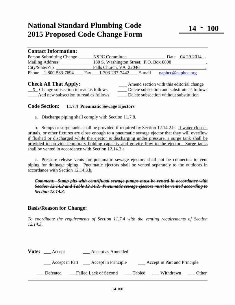
14-100
National Standard Plumbing Code 2015 Proposed Code Change Form
14 - 100
Contact Information: Person Submitting Change NSPC Committee Date 04-29-2014 . Mailing Address 180 S. Washington Street, P.O. Box 6808 . City/State/Zip Falls Church, VA 22046 . Phone 1-800-533-7694 Fax 1-703-237-7442 E-mail [email protected] Check All That Apply: ___ Amend section with this editorial change __X_ Change subsection to read as follows ____ Delete subsection and substitute as follows ____ Add new subsection to read as follows ____ Delete subsection without substitution Code Section: 11.7.4 Pneumatic Sewage Ejectors a. Discharge piping shall comply with Section 11.7.8. b. Sumps or surge tanks shall be provided if required by Section 12.14.2.b. If water closets, urinals, or other fixtures are close enough to a pneumatic sewage ejector that they will overflow if flushed or discharged while the ejector is discharging under pressure, a surge tank shall be provided to provide temporary holding capacity and gravity flow to the ejector. Surge tanks shall be vented in accordance with Section 12.14.3.a c. Pressure release vents for pneumatic sewage ejectors shall not be connected to vent piping for drainage piping. Pneumatic ejectors shall be vented separately to the outdoors in accordance with Section 12.14.3.b.
Comment: Sump pits with centrifugal sewage pumps must be vented in accordance with Section 12.14.2 and Table 12.14.2. Pneumatic sewage ejectors must be vented according to Section 12.14.3.
Basis/Reason for Change: To coordinate the requirements of Section 11.7.4 with the venting requirements of Section 12.14.3. Vote: ___ Accept ___ Accept as Amended
___ Accept in Part ___ Accept in Principle ___ Accept in Part and Principle
___ Defeated ___Failed Lack of Second ___ Tabled ___ Withdrawn ___ Other ______________________________________________________________________________

14-101
National Standard Plumbing Code 2015 Proposed Code Change Form
14 - 101
Contact Information: Person Submitting Change NSPC Committee Date 3-02-2014 . Mailing Address 180 S. Washington Street, P.O. Box 6808 . City/State/Zip Falls Church, VA 22046 . Phone 1-800-533-7694 Fax 1-703-237-7442 E-mail [email protected] Check All That Apply: ___ Amend section with this editorial change __X_ Change subsection to read as follows ____ Delete subsection and substitute as follows ____ Add new subsection to read as follows ____ Delete subsection without substitution Code Section: 11.7.6 Macerating Toilet Systems a. Macerating toilet systems shall comply with ASME A112.3.4 or CSA B45.9 ASME A112.3.4/CSA B45.9. b. (no changes) c. (no changes) d. (no changes) Basis/Reason for Change: ASME A112.3.4 and CSA B45.9 have been combined for plumbing fixtures with pumped waste, macerating toilet systems, and related components. ASME A112.3.4/CSA B45.9 is being added to 7.4.8 for water closets and Table 3.1.3 - Part V for plumbing fixtures with pumped waste. Vote: ___ Accept ___ Accept as Amended
___ Accept in Part ___ Accept in Principle ___ Accept in Part and Principle
___ Defeated ___Failed Lack of Second ___ Tabled ___ Withdrawn ___ Other ______________________________________________________________________________

14-102
National Standard Plumbing Code 2015 Proposed Code Change Form
14 - 102
Contact Information: Person Submitting Change NSPC Committee Date 03-22-2014 . Mailing Address 180 S. Washington Street, P.O. Box 6808 . City/State/Zip Falls Church, VA 22046 . Phone 1-800-533-7694 Fax 1-703-237-7442 E-mail [email protected] Check All That Apply: ___ Amend section with this editorial change __X_ Change subsection to read as follows ____ Delete subsection and substitute as follows ____ Add new subsection to read as follows ____ Delete subsection without substitution Code Section: 11.9 BRANCH CONNECTIONS NEAR THE BASE OF DRAIN STACKS a. Horizontal branch drain connections shall not be made within 10 pipe diameters downstream from the base of a stack. b. A relief vent shall be provided for stacks of five or more branch intervals, either above the base of the stack or within 10 pipe diameters downstream from the base of the stack. c. Branch drains shall not connect between the base of a stack and its relief vent. See Figures 11.9 and 12.3.1 a. Branch drain connections near the base of drain stacks that do not have vent stacks shall be not less than 2 feet above the base of the stack and not less than 10 pipe diameters downstream from the base of the stack. b. Where drain stacks have vent stacks in accordance with Section 12.3.1, branch drain connections near the base of the drain stack shall be coordinated with the location of its pressure relief connection by the vent stack.
1. If the pressure relief connection by the vent stack is above the base of the drain stack, there shall be no branch drain connections to the drain stack between its pressure relief connection and its base. 2. If the pressure relief connection by the vent stack is to the building drain beyond the base of the drain stack, there shall be no branch drain connections to the building drain between its pressure relief connection and the base of the drain stack.
See Figures 11.9 and 12.3.1 1.2 Pressure Relief Connection: For drain stacks that require a vent stack, their pressure relief connection is the lower connection of their vent stack to a point near the base of the drain stack to relieve the increased pressure at that point.

14-102
Basis/Reason for Change: To coordinate Section 11.9 with the requirements for pressure relief connections to drain stacks by their vent stack in Section 12.3.1. Pressure relief at the base of drain stacks with 5 or more branch intervals is the purpose of vent stacks. Vote: ___ Accept ___ Accept as Amended
___ Accept in Part ___ Accept in Principle ___ Accept in Part and Principle
___ Defeated ___Failed Lack of Second ___ Tabled ___ Withdrawn ___ Other ______________________________________________________________________________

14-103
National Standard Plumbing Code 2015 Proposed Code Change Form
14 - 103
Contact Information: Person Submitting Change NSPC Committee Date 4-29-2014 . Mailing Address 180 S. Washington Street, P.O. Box 6808 . City/State/Zip Falls Church, VA 22046 . Phone 1-800-533-7694 Fax 1-703-237-7442 E-mail [email protected] Check All That Apply: ___ Amend section with this editorial change __X_ Change subsection to read as follows ____ Delete subsection and substitute as follows ____ Add new subsection to read as follows ____ Delete subsection without substitution Code Section: 12.3.1 Stack Vents and Vent Stacks a. Stack vents shall extend from the top of a drainage stack, full size of the stack, to a vent stack or to an outdoor vent terminal. b. A vent stack shall be provided for drainage stacks having five or more branch intervals. c. Where drainage stacks have five or more branch intervals, the vent stack Where vent stacks are provided, their lower connection shall connect to near the base of the drainage stack as a relief vent for pressure relief, shall be either: 1. To to the drainage stack at or below the lowest fixture branch its lowest branch
connection or, 2. To to the building drain within 10 pipe diameters downstream from the base of
the drainage stack d. The upper connection of vent stacks shall be to the stack vent for the drain stack or to an outdoor vent terminal. d. e. Vent stacks shall also be permitted to be provided for drainage stacks having less than five branch intervals. See Figure 12.3.1 f. Stack vents and vent stacks shall be sized in accordance with Section 12.16.4. See Figure 12.3.1 Basis/Reason for Change: To clarify the requirements for the installation of stack vents and vent stacks. Vote: ___ Accept ___ Accept as Amended
___ Accept in Part ___ Accept in Principle ___ Accept in Part and Principle
___ Defeated ___Failed Lack of Second ___ Tabled ___ Withdrawn ___ Other ______________________________________________________________________________

14-104
National Standard Plumbing Code 2015 Proposed Code Change Form
14 - 104
Contact Information: Person Submitting Change NSPC Committee Date 04-03-2014 . Mailing Address 180 S. Washington Street, P.O. Box 6808 . City/State/Zip Falls Church, VA 22046 . Phone 1-800-533-7694 Fax 1-703-237-7442 E-mail [email protected] Check All That Apply: ___ Amend section with this editorial change __X_ Change subsection to read as follows ____ Delete subsection and substitute as follows ____ Add new subsection to read as follows ____ Delete subsection without substitution Code Section: 12.6 VENT SLOPES AND CONNECTIONS 12.6.1 Vent Slope Vent and branch vent pipes shall be free from drops and sags and be sloped and connected as to to drain by gravity to the drainage system. Vent piping 2-inch size and smaller shall be sloped not less than 1/4 inch per foot. Vent piping 3-inch size and larger shall be sloped not less than 1/8 inch per foot. See Figure 12.6.1 12.6.2.2 Slope of Horizontal Vent The portion of the horizontal vent installed below the flood level rim as permitted in Section 12.6.2.1 shall be installed with the required slope to drain by gravity to the drainage system in accordance with Section 12.6.1. See Figure 12.6.2-B Basis/Reason for Change: To indicate the required minimum slopes for vent piping. Vote: ___ Accept ___ Accept as Amended
___ Accept in Part ___ Accept in Principle ___ Accept in Part and Principle
___ Defeated ___Failed Lack of Second ___ Tabled ___ Withdrawn ___ Other ______________________________________________________________________________

14-105
National Standard Plumbing Code 2015 Proposed Code Change Form
14 - 105
Contact Information: Person Submitting Change NSPC Committee Date 03-28-2014 . Mailing Address 180 S. Washington Street, P.O. Box 6808 . City/State/Zip Falls Church, VA 22046 . Phone 1-800-533-7694 Fax 1-703-237-7442 E-mail [email protected] Check All That Apply: ___ Amend section with this editorial change ____ Change subsection to read as follows ____ Delete subsection and substitute as follows ____ Add new subsection to read as follows __X_ Delete subsection without substitution Code Section: 12.8 FIXTURE VENTS 12.8.2 Provision for Venting Future Fixtures On new contruction of residential dwelling units with basements, a 2” minimum size vent shall be installed between the basement and attic or tied into an existing, properly sized vent and capped for future use. Basis/Reason for Change: There are no requirements for where the future vent connection is to be located and how accessible it must be. What is its “proper” size? It may never be used. The future addition of plumbing fixtures would require more modifications than a plumbing vent. Vote: ___ Accept ___ Accept as Amended
___ Accept in Part ___ Accept in Principle ___ Accept in Part and Principle
___ Defeated ___Failed Lack of Second ___ Tabled ___ Withdrawn ___ Other ______________________________________________________________________________

National Standard Plumbing Code 2015 Proposed Code Change Form Deadline April 30, 2014
14 - 106
14-106
Contact Information: Person Submitting Change: Dan O’Gorman, CPD Date: April 30, 2014 Jurisdiction/Company: Mailing Address 10 Albany Street City/State/Zip: Edison, New Jersey 08837 Phone 732-661-1935 Fax 732-661-9326 E-mail [email protected] IMPORTANT: Please review the attached instruction sheet regarding proposed code changes. Check All That Apply: Amend section with this editorial change Change subsection to read as follows Delete subsection and substitute as follows Add new subsection to read as follows X Delete subsection without substitution Code Section: 12.16.6 Aggregate Size of Vent Terminals C. The aggregate cross-sectional area of all vent terminals serving g a sewer shall be not less than the cross sectional area of the minimum required size of the building drain they serve, at the point where it connects to the building sewer. (See Table 12.16.6 for cross-sectional areas of pipe) EXCEPTION: The aggregate cross –sectional area requirement shall be exclusive of any requirements to prevent frost closure under Section 12.5 Basis/Reason for Change: Aggregate cross-sectional area is not required to for a DWV System to function, based on engineering practice and The U.S. Department of Commerce Report BMS66, Building Materials and Structures. Code sections 12.16.6 update for the industry. Vote: ___ Accept ___ Accept as Amended
___ Accept in Part ___ Accept in Principle ___ Accept in Part and Principle
___ Defeated ___Failed Lack of Second ___ Tabled ___ Withdrawn ___ Other ____________________________________________________________________________________

14-107
National Standard Plumbing Code 2015 Proposed Code Change Form
14 - 107
Contact Information: Person Submitting Change NSPC Committee Date 02-19-2014 . Mailing Address 180 S. Washington Street, P.O. Box 6808 . City/State/Zip Falls Church, VA 22046 . Phone 1-800-533-7694 Fax 1-703-237-7442 E-mail [email protected] Check All That Apply: ___ Amend section with this editorial change ____ Change subsection to read as follows ____ Delete subsection and substitute as follows __X_ Add new subsection to read as follows ____ Delete subsection without substitution Code Sections: Sections 12.13 and 12.16 – Battery Venting 12.13 CIRCUIT AND LOOP VENTING
12.13.1 Battery Venting a. A maximum of eight floor-outlet water closets, showers, bathtubs, or floor drains connected in battery on a horizontal branch drain shall be permitted to be battery vented. EXCEPTION: Blowout type water closets. b. Each fixture drain shall connect horizontally to the horizontal branch drain being so vented. c. The horizontal branch battery-vented drain shall be considered as a vent extending from the most downstream fixture drain connection to the most upstream fixture drain connection. d. Back-outlet water closets and wall-mounted urinals shall be permitted to be battery vented provided that no floor-outlet fixtures are connected to the same horizontal branch battery-vented drain. EXCEPTION: Back-outlet blowout type water closets. e. The battery vent shall be a circuit or loop vent connected to the horizontal branch drain between the two most upstream fixture drains and shall be installed in accordance with Section 12.6. f. The entire length of the vent vented section of the horizontal branch battery-vented drain shall be uniformly sized for the total drainage discharge fixture units (DFU) connected thereto. g. The maximum slope of the horizontal branch battery-vented drain shall be 1 inch per foot. h. A relief vent shall be provided on battery vented horizontal branch drains on lower floors that have four or more water closets connected on the lower floors of a drain stack or connect to the building drain or a branch of the building drain. i. The relief vent shall connect to the horizontal branch battery-vented drain between the stack and the its most downstream fixture drain connection and its connection to a drain stack, the building drain, or branch of the building drain.

14-107
j. Relief vents shall be installed in accordance with Section 12.6. k. Circuit, loop, and relief vents shall be permitted to be a fixture drain or fixture branch connect to a fixture drain, common vent, or continuous vent for fixtures located within the same branch interval as the battery vented horizontal branch drain. EXCEPTION: No Fixture vents for more than four drainage units (DFU) shall discharge to the not connect to a battery vent. (See Section 12.12.4). l. Lavatories and similar fixtures shall be permitted to connect to the horizontal branch battery-vented drain, either horizontally or vertically, provided that, (1) the fixtures are on the same floor as the battery-vented drain, and (2) the fixtures have individual, common, or continuous vents. EXCEPTIONS: (1) Fixtures that are not located on the same floor as the battery-vented fixtures. (2) Fixtures that do not have an individual, common, or continuous vent. m. Batteries of more than eight battery-vented fixtures shall have a circuit or loop vent for each group of eight or less fixtures. n. Where there are two or more groups of battery-vented fixtures, the horizontal branch drain for each downstream group shall be sized for the total discharge drainage fixture units (DFU) into that group, including any upstream groups and the fixtures within the group being sized. o. Horizontal battery-vented drains that connect to drain stacks shall be sized as horizontal fixture branches in accordance with Table 11.5.1B. p. Horizontal battery-vented drains that connect to the building drain or a branch of the building drain shall be sized as a branch of the building drain in accordance with Table 11.5.1A. See Figure 12.13.1 and the definitions of “Battery of Fixtures”,”Vent, Circuit”, and “Vent, Loop”. 12.13.2 Joining Parallel Branches Where parallel branches of up to eight battery-vented fixtures each are joined prior to connecting to a stack or building drain, the common downstream piping shall be sized for the combined total fixture unit (DFU) load of both branches. A relief vent shall be provided on the common downstream piping when the parallel branches serve a combined total of four or more water closets and connect to a stack receiving drainage from an upper floor. 12.13.3 Vent Connections Circuit, loop, and relief vent connections to battery-vented horizontal drain branches horizontal battery-vented drains shall be taken off at a vertical angle or from of the top of the horizontal drain. See Figure 12.16.2 12.13.4 Fixtures Back-to-Back in Battery When fixtures are connected to one horizontal branch battery-vented drain through a double wye or a sanitary tee in a vertical position, a common vent for each two fixtures back-to-back or double connection shall be provided. The common vent shall be installed in a vertical position as a continuation of the double drain connection.

14-107
Figure 12.13.1 CIRCUIT AND LOOP VENTING BATTERIES OF FIXTURES NOTES 1. Battery vented horizontal branch drains can serve a mixture of two to eight water
closets, floor drains, bathtubs, shower stalls, and other floor-outlet fixtures. 2. Battery vented fixtures The fixtures must connect horizontally to the
horizontal branch battery-vented drain. 3. The entire length of the horizontal branch battery-vented drain must be sized for the
total connected DFU load for the branch. The slope of the drain must not exceed 1” 1 inch per foot.
4. The developed length of fixture trap arms must be within the limits of Table 12.8.1 for the given pipe size of the trap arm.
5. Lavatories, sinks, and wall-mounted urinals Lavatories and sinks can connect horizontally or vertically to the horizontal branch battery-vented drain, but they must be independently vented.
6. Relief vents are required where horizontal branch battery-vented drains on lower floors serve more than four water closets on the lower floors of a drain stack or connect to the building drain or a branch of the building drain.
7. Fixtures are permitted to drain into circuit, loop and relief vents. A 2” vent can drain 2 DFU. A 3” vent can drain 4 DFU.
8. Back-outlet water closets and wall-mounted urinals that are battery-vented must connect horizontally to the horizontal drain branch battery-vented drain with no vertical piping.
12.16 SIZE AND LENGTH OF VENTS
12.16.2 Size of Circuit or Loop Vents Circuit and loop vents shall not be less than one-half the size of the horizontal drainage branch drain that they serve. See Figure 12.16.2 Figure 12.16.2 THE SIZE OF CIRCUIT AND LOOP VENTS NOTES 1. A lower floor is shown. It requires a relief vent because there are more than 4 water
closets on the branch horizontal battery-vented drain. 2. The horizontal branch battery-vented drain is 4” size. 3. The circuit vent must be 2” minimum size per Section 12.16.2. 4. The relief vent must be 2” minimum size per Section 12.16.3. 12.16.3 Size of Relief Vents a. The size of relief vents for circuit or loop vented branches of the drainage system shall be not less than one-half the size of the branch horizontal battery-vented drain being served.
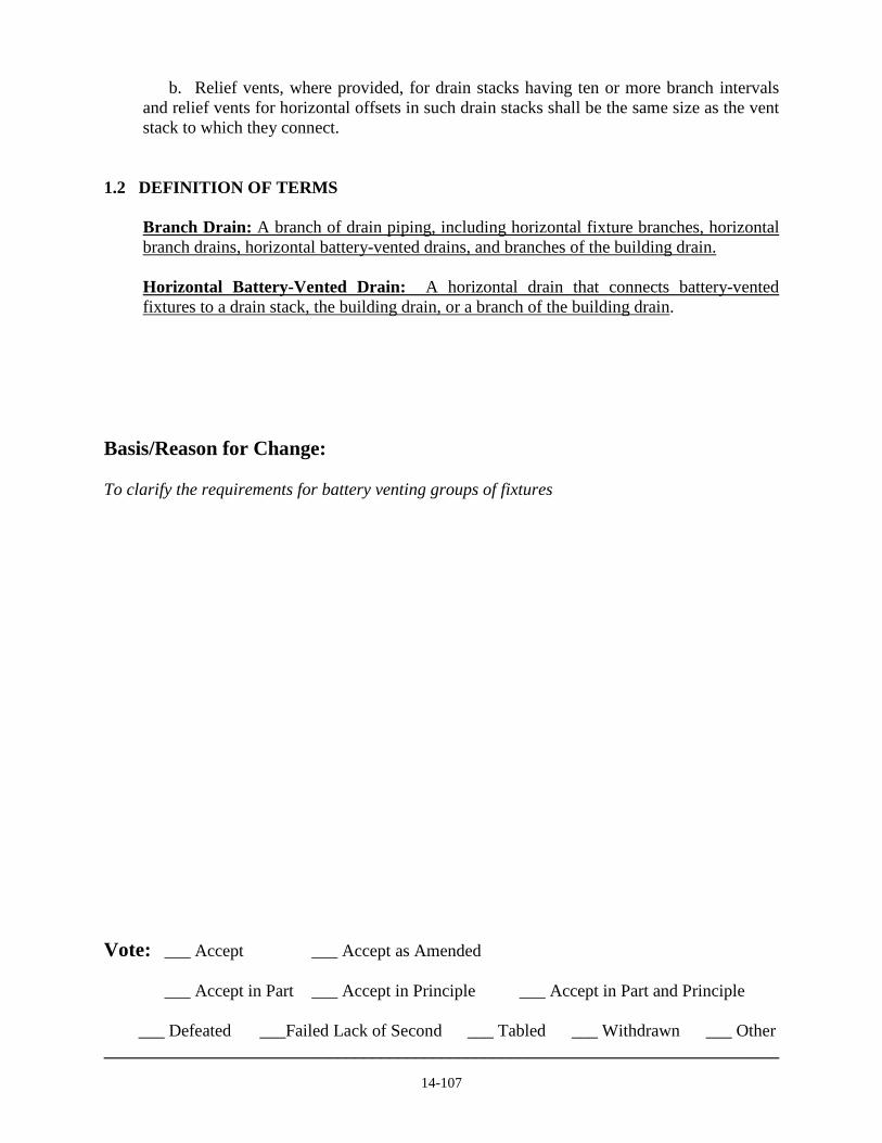
14-107
b. Relief vents, where provided, for drain stacks having ten or more branch intervals and relief vents for horizontal offsets in such drain stacks shall be the same size as the vent stack to which they connect.
1.2 DEFINITION OF TERMS Branch Drain: A branch of drain piping, including horizontal fixture branches, horizontal branch drains, horizontal battery-vented drains, and branches of the building drain. Horizontal Battery-Vented Drain: A horizontal drain that connects battery-vented fixtures to a drain stack, the building drain, or a branch of the building drain.
Basis/Reason for Change: To clarify the requirements for battery venting groups of fixtures Vote: ___ Accept ___ Accept as Amended
___ Accept in Part ___ Accept in Principle ___ Accept in Part and Principle
___ Defeated ___Failed Lack of Second ___ Tabled ___ Withdrawn ___ Other ______________________________________________________________________________

14-108
National Standard Plumbing Code 2015 Proposed Code Change Form
14 - 108
Contact Information: Person Submitting Change NSPC Committee Date 04-29-2014 . Mailing Address 180 S. Washington Street, P.O. Box 6808 . City/State/Zip Falls Church, VA 22046 . Phone 1-800-533-7694 Fax 1-703-237-7442 E-mail [email protected] Check All That Apply: ___ Amend section with this editorial change __X_ Change subsection to read as follows ____ Delete subsection and substitute as follows ____ Add new subsection to read as follows ____ Delete subsection without substitution Code Section: 12.14 VENTING OF BUILDING SUBDRAIN SYSTEMS 12.14.1 Fixture Venting Fixtures and gravity drainage piping in a building subdrain syatem shall be vented in the same manner as a conventional gravity drainage system and shall be permitted to connect to vent piping for fixtures and gravity drainage piping that are not part of the subdrain system. 12.14.2 Sump Pits a. The minimum size and maximum length of vents for atmospheric sump pits shall be as indicated in Table 12.14.2. b. Where subdrain systems utilize pneumatic sewage ejectors, atmospheric sump pumps or surge tanks shall be provided if water closets, urinals, or other fixtures are close enough to the ejector that they will overflow if flushed while the ejector is discharging. c. The atmospheric vents from sump pits and surge tanks shall be permitted to be connected to gravity vent piping for fixtures other than those served by the sump pump. 12.14.2 Subdrain Sump Pits for Atmospheric Pumps a. The vent pipe for an atmospheric subdrain sump pit shall be sized based on the discharge capacity of its sewage pump or ejector and the drainage load (DFU) connected to the pit, whichever is larger. 1. The required vent pipe size and length based on the sewage pump or ejector capacity
(GPM) shall be determined from Table 12.14.2. 2. The required vent pipe size and length based on the connected drainage load (DFU)
shall be determined from Table 12.16.4. b. The atmospheric vent pipe from a sump pit shall be permitted to be connected to gravity vent piping for fixtures other than those served by the sump pit. The sump pit vent shall carry the DFU load on the pit if it is connected to other vent piping and combined with their DFU loads.

14-108
12.14.3 Pneumatic Sewage Ejectors a. When a pneumatic sewage ejector requires a surge tank in Section 11.7.4, the tank shall be vented the same as an atmospheric sump pit. The vent shall be sized based on its connected DFU load. b. Pressure release vents for pneumatic sewage ejectors shall extend to a an outdoor vent terminal that is separate from any gravity system vents. Such pressure release vents shall be of sufficient size to reduce the ejector tank to atmospheric pressure within 10 seconds after discharge, but not less than 1-1/4” pipe size. NOTES FOR TABLE 12.14.2. 1. The lengths in the table are the developed lengths of the vent pipes in feet. An allowance has
been made for entrance losses and friction for the pipe and fittings. 2. (no change) 3. (no change) 4. (no change) Basis/Reason for Change: To clarify the requirements for venting building subdrain piping systems. Vote: ___ Accept ___ Accept as Amended
___ Accept in Part ___ Accept in Principle ___ Accept in Part and Principle
___ Defeated ___Failed Lack of Second ___ Tabled ___ Withdrawn ___ Other ______________________________________________________________________________

14-109
National Standard Plumbing Code 2015 Proposed Code Change Form
14 - 109
Contact Information: Person Submitting Change NSPC Committee Date 02-22-2014 . Mailing Address 180 S. Washington Street, P.O. Box 6808 . City/State/Zip Falls Church, VA 22046 . Phone 1-800-533-7694 Fax 1-703-237-7442 E-mail [email protected] Check All That Apply: ___ Amend section with this editorial change ____ Change subsection to read as follows ____ Delete subsection and substitute as follows ____ Add new subsection to read as follows __X_ Delete subsection without substitution Code Section: 12.16 SIZE AND LENGTH OF VENTS Delete Table 12.16 SIZE AND LENGTH OF VENTS in the 2012 NSPC. Basis/Reason for Change: Table 12.16 was replaced by Table 12.16.4 – SIZE AND LENGTH OF VENT STACKS in the 2013 Supplement to the NSPC. Vote: ___ Accept ___ Accept as Amended
___ Accept in Part ___ Accept in Principle ___ Accept in Part and Principle
___ Defeated ___Failed Lack of Second ___ Tabled ___ Withdrawn ___ Other ______________________________________________________________________________

14-110
National Standard Plumbing Code 2015 Proposed Code Change Form
14 - 110
Contact Information: Person Submitting Change NSPC Committee Date 04-29-2014 . Mailing Address 180 S. Washington Street, P.O. Box 6808 . City/State/Zip Falls Church, VA 22046 . Phone 1-800-533-7694 Fax 1-703-237-7442 E-mail [email protected] Check All That Apply: ___ Amend section with this editorial change __X_ Change subsection to read as follows ____ Delete subsection and substitute as follows ____ Add new subsection to read as follows ____ Delete subsection without substitution Code Section: 12.16 SIZE AND LENGTH OF VENTS 12.16.4 Size of Stack Vents and Vent Stacks a. Stack vents shall be not less than the full pipe size of the top of the drain stack that they serve are connected to.
b. Vent stacks, where required, shall be sized in accordance with Table 12.16.4, based on the total drainage fixture unit load (DFU) at the base of the drain stack that they serve. Connections of branch vents to the vent stack from fixtures on floor levels above the base of the drain stack shall not increase its size affect the size of the vent stack.
COMMENT: Where vent stacks are required for drain stacks, the drain stack and its stack vent must be the full size of the drain stack at its base. c. For the purpose of sizing vent stacks, the length of a vent stack in Table 12.16.4 shall be its developed length from its pressure relief connection to near the base of the drain stack being vented to its connection to its the stack vent at the top of the drain stack. If not connected to its the stack vent, its extension the vent stack shall extend to an outdoor vent terminal. Basis/Reason for Change: To clarify the sizing of stack vents and vent stacks. Vote: ___ Accept ___ Accept as Amended
___ Accept in Part ___ Accept in Principle ___ Accept in Part and Principle
___ Defeated ___Failed Lack of Second ___ Tabled ___ Withdrawn ___ Other ______________________________________________________________________________

13-111
National Standard Plumbing Code 2015 Proposed Code Change Form
14 - 111
Contact Information: Person Submitting Change NSPC Committee Date 04-29-2014 . Mailing Address 180 S. Washington Street, P.O. Box 6808 . City/State/Zip Falls Church, VA 22046 . Phone 1-800-533-7694 Fax 1-703-237-7442 E-mail [email protected] Check All That Apply: ___ Amend section with this editorial change __X_ Change subsection to read as follows ____ Delete subsection and substitute as follows ____ Add new subsection to read as follows ____ Delete subsection without substitution Code Section: Chapter 13 Storm Water Drainage 13.1.6 Areaway Drains a. Drainage shall be provided for open areaways below grade where storm water may accumulate. Areaways include outdoor spaces that provide access to basements or floor levels of a building that are below grade. Drains in such areas shall be sized according to Table 13.6.2 and shall include strainers as required for roof drains or floor drains. b. Areaway drains shall not connect to a foundation drain. Drains for individual areaways that collect rainwater from more than 100 square feet of space shall not be connected to a foundation drain. EXCEPTION: Areaways not exceeding 100 square feet in area. See Figure 13.1.6 Figures 13.1.6 and 1.2.6 Basis/Reason for Change: To clarify that draining areaways that are subject to limited rainwater to a foundation drain is permissible rather than an exception to being prohibited. Figures 13.1.6 and 1.2.6 illustrate the requirements of Section 13.1.6. Vote: ___ Accept ___ Accept as Amended
___ Accept in Part ___ Accept in Principle ___ Accept in Part and Principle
___ Defeated ___Failed Lack of Second ___ Tabled ___ Withdrawn ___ Other ______________________________________________________________________________

14-112
National Standard Plumbing Code 2015 Proposed Code Change Form
14- - 112
Contact Information: Person Submitting Change NSPC Committee Date 03-26-2014 . Mailing Address 180 S. Washington Street, P.O. Box 6808 . City/State/Zip Falls Church, VA 22046 . Phone 1-800-533-7694 Fax 1-703-237-7442 E-mail [email protected] Check All That Apply: ___ Amend section with this editorial change __X_ Change subsection to read as follows ____ Delete subsection and substitute as follows ____ Add new subsection to read as follows ____ Delete subsection without substitution Code Section: 13.1 GENERAL 13.1.9 Reserved Trench Drains Trench drains shall be installed in accordance with the manufacturer’s instructions for excavation, anchoring, assembly, and the connection of piping. Basis/Reason for Change: To include the installation of trench drains in Chapter 13 for storm drainage. Vote: ___ Accept ___ Accept as Amended
___ Accept in Part ___ Accept in Principle ___ Accept in Part and Principle
___ Defeated ___Failed Lack of Second ___ Tabled ___ Withdrawn ___ Other ______________________________________________________________________________

13-113
National Standard Plumbing Code 2015 Proposed Code Change Form
14 - 113
Contact Information: Person Submitting Change NSPC Committee Date 04-29-2014 . Mailing Address 180 S. Washington Street, P.O. Box 6808 . City/State/Zip Falls Church, VA 22046 . Phone 1-800-533-7694 Fax 1-703-237-7442 E-mail [email protected] Check All That Apply: ___ Amend section with this editorial change ____ Change subsection to read as follows ____ Delete subsection and substitute as follows __X_ Add new subsection to read as follows ____ Delete subsection without substitution Code Sections: 13.1.5 and 13.1.13 13.1.5 Foundation Drains g. The water supply to water-operated storm water sump pumps shall be protected from backflow in accordance with Section 10.5 Water-operated sump pumps shall comply with Section 13.1.13. 13.1.13 Water-Operated Sump Pumps a. Water-operated sump pumps shall not be used as a primary sump pump. They shall be secondary to an electric-powered sump pump.
b. Backflow protection for the water supply to a water-operated sump pump shall comply with Section 10.5.13.d. Basis/Reason for Change: To limit water-powered sump pumps to being secondary to an electric-powered sump pump. Vote: ___ Accept ___ Accept as Amended
___ Accept in Part ___ Accept in Principle ___ Accept in Part and Principle
___ Defeated ___Failed Lack of Second ___ Tabled ___ Withdrawn ___ Other ______________________________________________________________________________

14-114
National Standard Plumbing Code 2015 Proposed Code Change Form
14 - 114
Contact Information: Person Submitting Change NSPC Committee Date 02-09-2014 . Mailing Address 180 S. Washington Street, P.O. Box 6808 . City/State/Zip Falls Church, VA 22046 . Phone 1-800-533-7694 Fax 1-703-237-7442 E-mail [email protected] Check All That Apply: ___ Amend section with this editorial change __X_ Change subsection to read as follows ____ Delete subsection and substitute as follows ____ Add new subsection to read as follows ____ Delete subsection without substitution Code Section: 13.4 13.4 LEADERS OR CONDUCTORS OR LEADERS AND CONNECTIONS 13.4.1 Not to be Used Improperly Connected Leaders and Except for combined building drains, stormwater conductors shall not be used as connected to soil, waste, or vent pipes nor shall soil, waste, or vent pipes be used as leaders connected to stormwater conductors. Basis/Reason for Change: Stormwater leaders are external to the building and there are not likely to be inadvertent connections to drain or vent piping within the building. Vote: ___ Accept ___ Accept as Amended
___ Accept in Part ___ Accept in Principle ___ Accept in Part and Principle
___ Defeated ___Failed Lack of Second ___ Tabled ___ Withdrawn ___ Other ______________________________________________________________________________

14-115
National Standard Plumbing Code 2015 Proposed Code Change Form
14 - 115
Contact Information: Person Submitting Change NSPC Committee Date 04-30-2014 Mailing Address 180 S. Washington Street, P.O. Box 6808 . City/State/Zip Falls Church, VA 22046 . Phone 1-800-533-7694 Fax 1-703-237-7442 E-mail [email protected] Check All That Apply: ___ Amend section with this editorial change __X_ Change subsection to read as follows ____ Delete subsection and substitute as follows ____ Add new subsection to read as follows ____ Delete subsection without substitution Code Section: 13.5 ROOF DRAINS 13.5.1 Compliance and Materials a. Roof drains shall comply with ASME A112.6.4 and be constructed of coated or galvanized cast iron, bronze, stainless steel, plastic, or other corrosion-resisting materials. Drains shall include any deck clamps or other appurtenances necessary for installation and coordination with the roofing system. b. The required safe live loads for the grates and top rims of light duty, medium duty, heavy duty, extra heavy duty, and special duty roof drains shall be based on the structural design of the roof. 13.5.2 Dome Strainers Roof areas shall be drained to roof drains having raised dome strainers with dome free areas complying with ASME A112.6.4 for general purpose roof drains and gutter or cornice roof drains. The minimum free dome area shall be one and one-half (1-1/2) times the area of the drain outlet connection. EXCEPTIONS: (1) Pitched roofs draining to hanging gutters. (2) Roof areas subject to pedestrian and/or vehicular traffic. 13.5.3 Flat Grates Roof drains for patios, sun decks, parking decks, and other areas subject to pedestrian and/or vehicular traffic shall have flat grates with a free inlet area complying with ASME A112.6.4 for parapet roof drains and promenade or deck roof drains. The minimum grate free area shall be two times the cross-sectional area of the drain outlet. Such drains shall not be located where they cannot be readily inspected and maintained on a regular basis.

14-115
13.5.4 Roof Drain Flashings The connection between roofs and roof drains that pass through the roof and into the interior of the building shall be made watertight by the use of proper flashing material. 13.5.5 Roof Drain Restrictions The roof drain size shall not be restricted by insertion of any roofing material or other objects to insure water flow into the drain. 13.5.6 Roof Drain Outlet Pipe Size a. The outlet pipe size of roof drains having vertical conductors outlets shall be not less than the pipe size required for vertical conductors storm drains in Table 13.6.1. b. The outlet pipe size for roof drains having horizontal outlets shall be not less than the pipe size required for horizontal storm drains in Table 13.6.2. Basis/Reason for Change: To coordinate Section 13.5 with ASME A112.6.4 for roof drains. Vote: ___ Accept ___ Accept as Amended
___ Accept in Part ___ Accept in Principle ___ Accept in Part and Principle
___ Defeated ___Failed Lack of Second ___ Tabled ___ Withdrawn ___ Other ______________________________________________________________________________

14-116
National Standard Plumbing Code 2015 Proposed Code Change Form
14 - 116
Contact Information: Person Submitting Change NSPC Committee Date 04-30-2014 Mailing Address 180 S. Washington Street, P.O. Box 6808 . City/State/Zip Falls Church, VA 22046 . Phone 1-800-533-7694 Fax 1-703-237-7442 E-mail [email protected] Check All That Apply: ___ Amend section with this editorial change __X_ Change subsection to read as follows ____ Delete subsection and substitute as follows ____ Add new subsection to read as follows ____ Delete subsection without substitution Code Section: 13.6 SIZE OF VERTICAL AND HORIZONTAL STORM DRAIN PIPING 13.6.1 Vertical Conductors Size of Vertical Storm Drain Piping a. Vertical storm water conductors drain piping shall be sized according to Table 13.6.1. b. Where a vertical pipe section is smaller than the following horizontal pipe section, the increase in size shall be made in the vertical pipe section. c. Where a vertical pipe section is smaller than the preceding horizontal pipe section, the reduction in size shall be made in the vertical pipe section. 13.6.2 Size of Horizontal Storm Drain Piping a. Horizontal storm drain piping shall be sized according to Table 13.6.2 - Part 1 or Part 2. Such piping includes horizontal offsets in storm water conductors vertical storm drains, building storm drains, building storm sewers, and branches thereof. b. The size of horizontal drain piping shall not be reduced in the direction of flow. c. b. The design flows in Table 13.6.2 - Parts 1 and 2 are based on fairly rough pipe with a Manning friction coefficient “n” = 0.015. Table 13.6.1 SIZE OF VERTICAL STORM WATER CONDUCTORS DRAINS Basis/Reason for Change: To clarify the sizing of vertical and horizontal storm drain piping. Vote: ___ Accept ___ Accept as Amended
___ Accept in Part ___ Accept in Principle ___ Accept in Part and Principle
___ Defeated ___Failed Lack of Second ___ Tabled ___ Withdrawn ___ Other ______________________________________________________________________________

14-117
National Standard Plumbing Code 2015 Proposed Code Change Form
14 - 117
Contact Information: Person Submitting Change NSPC Committee Date 04-30-2014 Mailing Address 180 S. Washington Street, P.O. Box 6808 . City/State/Zip Falls Church, VA 22046 . Phone 1-800-533-7694 Fax 1-703-237-7442 E-mail [email protected] Check All That Apply: ___ Amend section with this editorial change _____ Change subsection to read as follows ____ Delete subsection and substitute as follows __ X_ Add new subsection to read as follows ____ Delete subsection without substitution Code Section: Chapter 13 Storm Water Drainage 13.7 RESERVED AREA DRAINS AND TRENCH DRAINS Area drains and trench drains shall comply with Section 7.16, including the minimum required free area of the grates. The top load classification of the grates and top rims shall be adequate for the minimum live load requirement for their area of installation. Table 3.1.3 - Part V PLUMBING FIXTURES Area drains ……………………………………………………………ASME A112.6.3 Basis/Reason for Change: To add the requirements for area drains and trench drains in Chapter 13. Vote: ___ Accept ___ Accept as Amended
___ Accept in Part ___ Accept in Principle ___ Accept in Part and Principle
___ Defeated ___Failed Lack of Second ___ Tabled ___ Withdrawn ___ Other ______________________________________________________________________________

14-118
National Standard Plumbing Code 2015 Proposed Code Change Form
14 - 118
Contact Information: Person Submitting Change NSPC Committee Date 02-28-2014 . Mailing Address 180 S. Washington Street, P.O. Box 6808 . City/State/Zip Falls Church, VA 22046 . Phone 1-800-533-7694 Fax 1-703-237-7442 E-mail [email protected] Check All That Apply: ___ Amend section with this editorial change __X_ Change subsection to read as follows ____ Delete subsection and substitute as follows ____ Add new subsection to read as follows ____ Delete subsection without substitution Code Section: 14.3 MEDICAL GAS AND VACUUM PIPING SYSTEMS 14.3.2 Professional Qualifications of Installers, Inspectors and Verifiers Installers (including brazers), inspectors, and verifiers of medical gas and vacuum piping systsems shall meet the requirements of ANSI/ASSE 6000 - Professional Qualification Standard for Medical Gas Systems Installers, Inspectors, and Verifiers, or the equivalent. Installers, including brazers, of medical gas and vacuum piping systems shall meet the qualification requirements of ASSE 6000 or the equivalent. Basis/Reason for Change: The plumbing code does not apply to the qualifications of the inspectors and verifiers of medical gas and vacuum piping systems. Vote: ___ Accept ___ Accept as Amended
___ Accept in Part ___ Accept in Principle ___ Accept in Part and Principle
___ Defeated ___Failed Lack of Second ___ Tabled ___ Withdrawn ___ Other ______________________________________________________________________________

14-119
National Standard Plumbing Code 2015 Proposed Code Change Form
14 - 119
Contact Information: Person Submitting Change NSPC Committee Date 04-29-2014 Mailing Address 180 S. Washington Street, P.O. Box 6808 . City/State/Zip Falls Church, VA 22046 . Phone 1-800-533-7694 Fax 1-703-237-7442 E-mail [email protected] Check All That Apply: ___ Amend section with this editorial change __X_ Change subsection to read as follows ____ Delete subsection and substitute as follows ____ Add new subsection to read as follows ____ Delete subsection without substitution Code Section: Chapter 15 Tests and Maintenance 15.1 EXPOSURE OF WORK New, altered, extended or replaced plumbing shall be left uncovered and unconcealed until it has been inspected, tested and approved. Where such work has been covered or concealed before it is inspected, tested and approved, it shall be exposed for testing as required.
15.2 EQUIPMENT, MATERIAL, AND LABOR FOR TESTS Equipment, material and labor required for testing a plumbing system or part thereof shall be furnished provided by the installing contractor.
15.3 TESTING OF PLUMBING SYSTEMS 15.3.1 General New plumbing systems and parts of existing systems that have been altered, extended or repaired shall be tested as prescribed hereinafter to disclose leaks and defects only when required by the Authority Having Jurisdiction.
a. New plumbing systems shall be tested as prescribed hereinafter to disclose leaks and defects.
b. Where additions or changes are made to existing plumbing systems, the new work shall be tested or inspected to the degree necessary to disclose leaks and defects in the new work. 15.3.2 Exceptions a. Where required by the Authority Having Jurisdiction, where an existing concealed sewer or drain is reused as part of a new or renovated drainage system, the line shall be traced to its point of termination and shall be tested to determine that: 1. It is connected to the proper drainage system, such as sanitary or strom. 2. It will withstand a leak test, and, 3. It is free-flowing and not restricted.

14-119
Basis/Reason for Change: To clarify the requirements for testing new plumbing work for leaks and defects. Vote: ___ Accept ___ Accept as Amended
___ Accept in Part ___ Accept in Principle ___ Accept in Part and Principle
___ Defeated ___Failed Lack of Second ___ Tabled ___ Withdrawn ___ Other ______________________________________________________________________________

14-120
National Standard Plumbing Code 2015 Proposed Code Change Form
14 - 120
Contact Information: Person Submitting Change NSPC Committee Date 04-29-2014 . Mailing Address 180 S. Washington Street, P.O. Box 6808 . City/State/Zip Falls Church, VA 22046 . Phone 1-800-533-7694 Fax 1-703-237-7442 E-mail [email protected] Check All That Apply: ___ Amend section with this editorial change __X_ Change subsection to read as follows ____ Delete subsection and substitute as follows ____ Add new subsection to read as follows ____ Delete subsection without substitution Code Section: Chapter 17 Private Potable Water Supply Systems 17.1 GENERAL REGULATION REGULATIONS 17.1.1 Jurisdiction Applicability The regulations in this chapter apply to any private potable water supply system where plumbing fixtures are installed for human occupancy. 17.15 CROSS CONNECTIONS PRIVATE WATER SUPPLY SYSTEM RESTRICTIONS AND LIMITATIONS 17.15.1 Between Systems Restrictions An individual A private potable water supply system shall not be connected to another individual or a public water supply system unless approved in accordance with Section 10.4.4. 17.15.2 Between Properties Limitations No individual private potable water supply system shall serve more than one property unless authorized approved by the Authority Having Jurisdiction. Basis/Reason for Change: Chapter 17 applies to private potable water supply systems. Vote: ___ Accept ___ Accept as Amended
___ Accept in Part ___ Accept in Principle ___ Accept in Part and Principle
___ Defeated ___Failed Lack of Second ___ Tabled ___ Withdrawn ___ Other ______________________________________________________________________________

14-121
National Standard Plumbing Code 2015 Proposed Code Change Form
14 - 121
Contact Information: Person Submitting Change NSPC Committee Date 04-03-2014 . Mailing Address 180 S. Washington Street, P.O. Box 6808 . City/State/Zip Falls Church, VA 22046 . Phone 1-800-533-7694 Fax 1-703-237-7442 E-mail [email protected] Check All That Apply: ___ Amend section with this editorial change __X_ Change subsection to read as follows ____ Delete subsection and substitute as follows ____ Add new subsection to read as follows ____ Delete subsection without substitution Code Section: 17.9 WELL TERMINAL 17.9.1 Upper Well Terminal Well casing, curbs, and pitless adapaters Well casings and curbs shall terminate not less than eight inches above the finished ground surface or pump house floor and at least 24 inches above the maximum high water level where flooding occurs. No casing shall be cut off or cut in into below ground except to install a pitless adapter. Basis/Reason for Change: Pitless adapters are installed below grade as indicated in Figure 1.2.46. Vote: ___ Accept ___ Accept as Amended
___ Accept in Part ___ Accept in Principle ___ Accept in Part and Principle
___ Defeated ___Failed Lack of Second ___ Tabled ___ Withdrawn ___ Other ______________________________________________________________________________

14-122
National Standard Plumbing Code 2015 Proposed Code Change Form
14 - 122
Contact Information: Person Submitting Change NSPC Committee Date 3-01-2014 . Mailing Address 180 S. Washington Street, P.O. Box 6808 . City/State/Zip Falls Church, VA 22046 . Phone 1-800-533-7694 Fax 1-703-237-7442 E-mail [email protected] Check All That Apply: ___ Amend section with this editorial change __X_ Change subsection to read as follows ____ Delete subsection and substitute as follows ____ Add new subsection to read as follows ____ Delete subsection without substitution Code Section: 18.1 DEFINITIONS Trailer Coach Any camp-car, trailer, or other vehicle with or without motive power, designed and constructed to travel on the public thoroughfares in accordance with the provisions of the applicable State Vehicle Code and designed or used for human habitation. Basis/Reason for Change: States usually have a State Vehicle Code that is used and enforced by their Department of Motor Vehicles. Vote: ___ Accept ___ Accept as Amended
___ Accept in Part ___ Accept in Principle ___ Accept in Part and Principle
___ Defeated ___Failed Lack of Second ___ Tabled ___ Withdrawn ___ Other ______________________________________________________________________________

14-123
National Standard Plumbing Code 2015 Proposed Code Change Form
14 - 123
Contact Information: Person Submitting Change NSPC Committee Date 02-09-2014 . Mailing Address 180 S. Washington Street, P.O. Box 6808 . City/State/Zip Falls Church, VA 22046 . Phone 1-800-533-7694 Fax 1-703-237-7442 E-mail [email protected] Check All That Apply: ___ Amend section with this editorial change __X_ Change subsection to read as follows ____ Delete subsection and substitute as follows ____ Add new subsection to read as follows ____ Delete subsection without substitution Code Section: Chapter 18 Mobile Home & Travel Trailer Park Plumbing Requirements 18.5 WATER DISTRIBUTION SYSTEM 18.5.3 Connection Water Service Branch Components A control manual shutoff valve shall be installed on the water service branch, followed by an approved backflow preventer in accordance with ASSE 1024 or CSA B64.6 dual check backflow preventer on the discharge side of the control shutoff valve, with a pressure relief valve located on the discharge side of the backflow preventer, and with a hose connection or other approved trailer attachment on the trailer side of the relief valve. Each such The pressure relief valve shall be equipped with set for 125 psi and have a full-size drain discharge pipe with the end of the pipe not more than two feet or less than six inches above the ground and pointing downward. Such drain may terminate at other approved locations. No part of such drain the discharge pipe shall be trapped. No shut-off valve shall be installed between any such the pressure relief valve and the trailer that it serves. The backflow device and relief valve shall be located not less than 12 inches above the ground. Basis/Reason for Change: To clarify the requirements of Section 18.5.3 for the water service branch to trailer connections. Vote: ___ Accept ___ Accept as Amended
___ Accept in Part ___ Accept in Principle ___ Accept in Part and Principle
___ Defeated ___Failed Lack of Second ___ Tabled ___ Withdrawn ___ Other ______________________________________________________________________________

14-124
National Standard Plumbing Code 2015 Proposed Code Change Form
14 - 124
Contact Information: Person Submitting Change NSPC Committee Date 04-22-2014 . Mailing Address 180 S. Washington Street, P.O. Box 6808 . City/State/Zip Falls Church, VA 22046 . Phone 1-800-533-7694 Fax 1-703-237-7442 E-mail [email protected] Check All That Apply: ___ Amend section with this editorial change ____ Change subsection to read as follows ____ Delete subsection and substitute as follows __X_ Add new subsection to read as follows ____ Delete subsection without substitution Code Section: Chapter 19 Referenced Standards Add Sections 19.1 - Referenced Standards and 19.2 - Standards Organizations herein. Delete the existing list of Standards Organizations following Section 3.1.3. Add the following Table 19.1 with the list of referenced standards. Basis/Reason for Change: To list all of the referenced standards in the NSPC in Chapter 19.

14-124
Chapter 19 Referenced Standards
19.1 REFERENCED STANDARDS Table 19.1 lists the standards that are referenced within the requirements of this Code. Table 19.1 shows the designation number of the standard, its effective date, a date if reaffirmed, any addendums or amendments, its title, and the Sections and/or Tables in the Code where the standard is referenced. 19.2 STANDARDS ORGANIZATIONS AHAM Association of Home Appliance Manufacturers 111 19th Street NW, Suite 402 Washington, DC 20036 USA tel: 1-202-872-5955 fax: 1-202-872-9354 ANSI American National Standards Institute 25 West 43rd Street - 4th Floor New York, NY 10036 USA tel: 1-212-642-4900 fax: 1-212-398-0023 ASHRAE ASHRAE Headquarters 1791 Tullie Circle, N.E. Atlanta, GA 30329 tel: 1-404-636-8400 fax: 1-404-321-5478 ASME American Society of Mechanical Engineers International Three Park Avenue New York, NY 10016-5990 USA tel: 1-800-843-2763 fax: 1-212-591-7674 ASSE American Society of Sanitary Engineers International 901 Canterbury Road - Suite A Westlake, OH 44145 USA tel: 1-440-835-3040 fax: 1-440-835-3488 ASTM ASTM International 100 Barr Harbor Drive P.O. Box C700 West Conshohocken, PA 19428-2959 USA tel: 1-601-832-9585 fax: 1-601-832-9555 AWS American Welding Society 8669 NW 36 Street - #130 Miami, FL 33166-6672 tel: 1-8000-443-9353 fax: 1-305-443-9353 AWWA American Water Works Association 666 W. Quincy Avenue Denver, CO 80235 USA tel: 1-800-926-7337 fax: 1-303-347-0804
CISPI Cast Iron Soil Pipe Institute 1064 Delaware Avenue - South East Atlanta, GA 30316 USA tel: 1-404-622-0073 fax: 1-678-973-2845 CSA Canadian Standards Association 5060 Spectrum Way Mississauga, ON L4W 5N6 CANADA tel: 1-800-463-6727 fax: 1-416-747-2473 FM FM Global 270 Central Avenue P.O. Box 7500 Johnston, RI 02919-4923 USA tel: 1-401-275-3000 fax: 1-401-275-3029 IAPMO International Association of Plumbing and Mechanical Officials 4775 E. Philadelphia Street Ontario, CA 91761 USA tel: 1-909-472-4100 fax: 1-909-472-4150 ISEA International Safety Equipment Association 1901 N. Moore Street Arlington, VA 22209-1762 USA tel: 1-703-525-1695 fax: 1-703-528-2148 MSS Manufacturers Standardization Society 127 Park Street NE Vienna, VA 22180 USA tel: 1-703-281-6613 fax: 1-703-281-6671 NFPA National Fire Protection Association 1 Batterymarch Park Quincy, MA 02169-7471 USA tel: 1-617-770-3000 fax: 1-617-770-0700 NSF NSF International 789 N. Dixboro Road Ann Arbor, MI 48113-0140 USA tel: 1-800-673-6275 fax: 1-734-769-0109

14-124
PDI Plumbing and Drainage Institute 800 Turnpike Street - Suite 300 North Andover, MA 01845 USA tel: 1-800-589-8956 fax; 1-978-557-0721 UL Underwriters Laboratories Inc. 333 Pfingsten Road Northbrook, IL 60062-2096 USA tel: 1-847-272-8800 fax: 1-847-272-8129
Vote: ___ Accept ___ Accept as Amended
___ Accept in Part ___ Accept in Principle ___ Accept in Part and Principle
___ Defeated ___Failed Lack of Second ___ Tabled ___ Withdrawn ___ Other

TABLE 19.1 Referenced Standards AHAM DW-1 - 2010: Dishwashers ………………………………………………………………………………………………….…..………Table 3.1.3-VII, 7.15.1 AHAM FWD-1 - 2009: Food Waste Disposers ………………………………………………………………………………………….………Table 3.1.3-VII, 7.14.1 AHAM HLW-1 - 2010: Performance Evaluation Procedures for Household Clothes Washers ………………………………….………..……Table 3.1.3-VII, 7.13.1 ANSI Z4.3 - 1995 (R2005): Sanitation - Non-sewered Waste-Disposal Systems - Minimum Requirements ……………………….….………….2.24, Table 3.1.3-X ANSI Z21.10.1 - 2013: Gas Water Heaters - Volume I, Storage Water Heaters with Input Ratings of 75,000 Btu per Hour or Less ……....Table 3.1.3-VII, 10.15.11 ANSI Z21.10.1/CSA 4.1: Refer to ANSI Z21.10.1 or CSA 4.1 ………………………………………………… …………………………Table 3.1.3-VII, 10.15.11 ANSI Z21.10.3 - 2013: Gas Water Heaters - Volume III, Storage Water Heaters with Input Ratings above 75,000 Btu Per Hour, Circulating and Instantaneous ………. ……………………………………………………………………………………………………….………..….…..Table 3.1.3-VII, 10.15.11 ANSI Z21.10.3/CSA 4.3: Refer to ANSI Z21.10.3 or CSA 4.3 …....................................................................................................................Table 3.1.3-VII, 10.15.11 ANSI Z21.22 - 1999 (R2008): Relief Valves for Hot Water Supply Systems ……………………………………..…….…..Table 3.1.3-VIII, 10.16.7, Figure 10.16.7 ANSI Z21.22/CSA 4.4: Refer to ANSI Z21.22 or CSA 4.4 …………………………………………………………….…….Table 3.1.3-VIII, 10.16.7, Figure 10.16.7 ANSI/ISEA Z358.1 - 2009: American National Standard for Emergency Eyewash and Shower Equipment ………….…Table 3.1.3-V, Table 7.21.1 Note (17), 7.24 ASME A13.1 - 2007 (R2013) Scheme for the Identification of Piping Systems …………………………….…………….……………………….…………2.27, 10.21 ASME A112.1.2 - 2012: Air Gaps in Plumbing Systems (for Plumbing Fixtures and Water-Connected Receptors) …………………..Table 3.1.3-IX, 10.5.1, 10.5.3 ASME A112.1.3 - 2000 (R2010): Air Gap Fittings for Use with Plumbing Fixtures, Appliances, and Appurtenances ……………....Table 3.1.3-IX, 10.5.1, 10.5.3 ASME A112.3.1 - 2007: Stainless Steel Drainage Systems for Sanitary DWV, Storm, and Vacuum Applications, Above- and Below-Ground ……………………… …………………………………………………………………………………………Table 3.1.3-I, Table 3.5, Table 3.6, Table 3.7, 7.16.1 ASME A112.3.4 - 2013: Plumbing Fixtures with Pumped Waste and Macerating Toilet Systems ……………………….………………Table 3.1.3-X, 7.4.8, 11.7.6 ASME A112.3.4/CSA B45.9: Refer to ASME A112.3.4 or CSA B45.9 …………………………………………………….….…………Table 3.1.3-X, 7.4.8, 11.7.6 ASME A112.4.1 - 2009: Water Heater Relief Valve Drain Tubes ……………………………………………………………….……..……………..Table 3.1.3-VIII ASME A112.4.2 - 2009: Water Closet Personal Hygiene Devices ………………………………………………………………..…..…………..Table 3.1.3-VI, 7.7.1 ASME A112.4.3 - 1999 (R2010): Plastic Fittings for Connecting Water Closets to the Sanitary Drainage System …………………………………….Table 3.1.3-IV ASME A112.4.14 - 2004 (R2010): Manually Operated, Quarter-Turn Shutoff Valves for Use in Plumbing Systems …………………………..……Table 3.1.3-VIII ASME A112.6.1M - 1997 (R2012): Floor-Affixed Supports for Off-the-Floor Plumbing Fixtures for Public Use ………………………Table 3.1.3-VI, 3.3.12, 7.3.5 ASME A112.6.2 - 2000 (R2010): Framing-Affixed Supports for Off-the Floor Water Closets with Concealed Tanks …………….……Table 3.1.3-VI, 3.3.12, 7.3.5 ASME A112.6.3 - 2001 (R2007): Floor and Trench Drains …………..………………………….………………Table 3.1.3-V, 5.3.6, 7.16.1, Figure 7.16.2-A, 7.16.3 ASME A112.6.4 - 2003 (R2012): Roof, Deck, and Balcony Drains ………………………………………………………………Table 3.1.3-V, 13.5.1, 13.5.2, 13.5.3 ASME A112.6.7 - 2010: Sanitary Floor Sinks ………………....…………………………………………………………………..…..………….Table 3.1.3-V, 7.11.5 ASME A112.14.1 - 2003 (R2012): Backwater Valves ………………………………………………………….….………….…………………Table 3.1.3-VIII, 5.5.2 ASME A112.14.3 - 2000 (R2004): Grease Interceptors …………………………………………………………...………………Table 3.1.3-X, 6.1.4.2, 6.2.1.1, 6.2.2 ASME A112.14.4 - 2001 (R2012): Grease Removal Devices ……………………………………………………..………………Table 3.1.3-X, 6.1.4.2, 6.2.1.2, 6.2.2 ASME A112.14.6 - 2010: FOG (Fats, Oils, and Greases) Disposal Systems ……………………………………………………………………..Table 3.1.3-X, 6.2.1.4 ASME A112.18.1 - 2012: Plumbing Supply Fittings …………………………………………………….…………..Table 3.1.3-VI, 7.6.2, 7.7.1, 7.8.3, 7.10.2, 7.11.1 ASME A112.18.1/CSA B125.1: Refer to ASME A112.18.1 or CSA B125.1……………………………..…………Table 3.1.3-VI, 7.6.2, 7.7.1, 7.8.3, 7.10.2, 7.11.1 ASME A112.18.2 - 2011: Plumbing Waste Fittings ………………………………………………………………….…………….……..Table 3.1.3-VI, 3.2.1, 7.11.1 ASME A112.18.2/CSA B125.2: Refer to ASME A112.18.2 or CSA B125.2……………………………………………………..………Table 3.1.3-VI, 3.2.1, 7.11.1

ASME A112.18.3 - 2002 (R2012): Performance Requirements for Backflow Protection Devices and Systems in Plumbing Fixture Fittings ………..Table 3.1.3-IX ASME A112.18.6 - 2009: Flexible Water Connectors …………………………………………….……………………………………………Table 3.1.3-VI, 10.13 ASME A112.18.6/CSA B125.6: Refer to ASME A112.18.6 or CSA B125.6 ……………………………………………………………………Table 3.1.3-VI, 10.13 ASME A112.18.9 - 2011: Protectors/Insulators for Exposed Wastes and Supplies on Accessible Fixtures …………………………………..…….Table 3.1.3-VI, 7.2 ASME A112.19.1 - 2013: Enameled Cast Iron and Enameled Steel Plumbing Fixtures ……………………………………….…….Table 3.1.3-V, 7.6.1, 7.8.1, 7.11.1 ASME A112.19.1/CSA B45.2: Refer to ASME A112.19.1 or CSA B45.2 …………………………………………………..………Table 3.1.3-V, 7.6.1, 7.8.1, 7.11.1 ASME A112.19.2 - 2013: Ceramic Plumbing Fixtures …………………………………………….…….Table 3.1.3-V, 7.4.1, 7.4.2, 7.5.1, 7.5.2, 7.6.1, 7.7.1, 7.11.1 ASME A112.19.2/CSA B45.1: Refer to ASME A112.19.2 or CSA B45.1 ………………………………Table 3.1.3-V, 7.4.1, 7.4.2, 7.5.1, 7.5.2, 7.6.1, 7.7.1, 7.11.1 ASME A112.19.3 - 2008 (R2013): Stainless Steel Plumbing Fixtures …………………………………….………………………...…….Table 3.1.3-V, 7.6.1, 7.11.1 ASME A112.19.3/CSA B45.4: Refer to ASME A112.19.3 or CSA B45.4 ………………………….…………………….………………Table 3.1.3-V, 7.6.1, 7.11.1 ASME A112.19.5 - 2011 w/update 1: Flush Valves and Spuds for Water Closets, Urinals, and Tanks ………………….…………..…………………Table 3.1.3-VI ASME A112.19.7 - 2012: Hydromassage Bathtub Systems .………………………………………………………..………………………………Table 3.1.3-V, 7.9.2 ASME A112.19.7/CSA B45.10: Refer to ASME A112.19.7 or CSA B45.10 ….……………………………………………………………..……Table 3.1.3-V, 7.9.2 ASME A112.19.10 - 2003 (R2008): Dual Flush Devices for Water Closets …………..…………………………………..…………………………….Table 3.1.3-VI ASME A112.19.12 - 2006 (R2011): Wall Mounted, Pedestal Mounted, Adjustable, Elevating, Tilting, and Pivoting Lavatory, Sink, and Shampoo Bowl Carrier Systems and Drain Waste Systems ……………………………………………………………………Table 3.1.3-VI, 3.3.12, 7.2 ASME A112.19.14 - 2013: Six Liter Water Closets Equipped with a Dual Flushing Device ……………………………………….……………………Table 3.1.3-V ASME A112.19.15 - 2012: Bathtubs/Whirlpool Bathtubs with Pressure Sealed Doors ……………………………………………..…..…………Table 3.1.3-V, 7.8.1 ASME A112.19.17 - 2010: Manufactured Safety Vacuum Release Systems (SVRS) for Residential and Commercial Swimming Pool, Spa, Hot Tub, and Wading Pool Suction Systems ……………………………………………………………………………….….……………………Table 3.1.3-VI ASME A112.19.19 - 2006 (R2011): Vitreous China Non-water Urinals ………………………………………………………….………………Table 3.1.3-V, 7.5.1 ASME A112.36.2M - 1991 (R2012): Cleanouts ……………………………………………………………………………..……………..…………..Table 3.1.3-VIII ASME A112.1016 - 2011 w/updates 1 & 2: Performance Requirements for Automatic Compensating Valves for Individual Shower and Tub/Shower Combinations …………………………………………………………………………………………….Tables 3.1.3-VI, -VIII, 10.15.6 ASME A112.1016/ASSE 1016/CSA B125.16: Refer to ASME A112.1016, ASSE 1016, or CSA B125.16……………..….…………Tables 3.1.3-VI, -VIII, 10.15.6 ASME B1.20.1 - 2013: Pipe Threads, General Purpose (Inch) ……………………………………..……………………………..………………Table 3.1.3-IV, 4.2.2 ASME B16.3 - 2011: Malleable Iron Threaded Fittings: Classes 150 and 300 …………………………………………………………………Table 3.1.3-I, Table 3.4 ASME B16.4 - 2011: Gray Iron Threaded Fittings: Classes 125 and 250 ………………………………………………………………………Table 3.1.3-I, Table 3.4 ASME B16.5 - 2013: Pipe Flanges and Flanged Fittings: NPS 1/2 through NPS 24 Metric/Inch Standard ……………………....……………Table 3.1.3-I, Table 3.4 ASME B16.12 - 2009: Cast Iron Threaded Drainage Fittings ……………………………………………………………Table 3.1.3-I, Table 3.5, Table 3.6, Table 3.7 ASME B16.14 - 2013: Ferrous Pipe Plugs, Bushings, and Locknuts with Pipe Threads …………………………….…………………………….………Table 3.1.3-I ASME B16.15 - 2013: Cast Copper Alloy Threaded Fittings: Classes 125 and 250 ………………………………….……………………….Table 3.1.3-II, Table 3.4 ASME B16.18 - 2012: Cast Copper Alloy Solder Joint Pressure Fittings ……………………………………..……..…Table 3.1.3-II, Table 3.4, 4.2.4, 4.2.6, 10.20.4 ASME B16.22 - 2013: Wrought Copper and Copper Alloy Solder-Joint Pressure Fittings ………………....…Table 3.1.3-II, Table 3.4, 4.2.4, 4.2.6, 4.2.8.2, 10.20.4 ASME B16.23 - 2011: Cast Copper Alloy Solder Joint Drainage Fittings: DWV ……………………….………Table 3.1.3-II, Table 3.5, Table 3.6, Table 3.7, 4.2.4 ASME B16.24 - 2011: Cast Copper Alloy Pipe Flanges and Flanged Fittings, Classes 150, 300, 400, 600, 800, 1500, and 2500 ……Table 3.1.3-II, Table 3.4, 4.2.4 ASME B16.26 - 2013: Cast Copper Alloy Fittings for Flared Copper Tubes ………………………………………………..…………Table 3.1.3-II, Table 3.4, 4.2.5 ASME B16.29 - 2012: Wrought Copper and Wrought Copper Alloy Solder-Joint Drainage Fittings - DWV ….Table 3.1.3-II, Table 3.5, Table 3.6, Table 3.7, .4.2.4 ASME B16.50 - 2013: Wrought Copper and Copper Alloy Braze-Joint Pressure Fittings ……………….……………………Table 3.1.3-II, Table 3.4, 4.2.4, 4.2.8.2 ASME B16.51 - 2013: Copper and Copper Alloy Press-Connect Pressure Fittings ……………………….……..…………………………..Table 3.1.3-II, Table 3.4

ASSE 1001 - 2008: Performance Requirements for Atmospheric Type Vacuum Breakers…………………………..…..………Table 3.1.3-IX, 7.8.4, 10.5.3, 10.5.10 ASSE 1002 - 2008: Performance Requirements for Anti-Siphon Fill Valves for Water Closet Tanks …………………….……………………Table 3.1.3-VI, 7.19.3 ASSE 1003 - 2009: Performance Requirements for Water Pressure Reducing Valves for Domestic Water Distribution Systems………..…Table 3.1.3-VIII, 10.14.6 ASSE 1004 - 2008: Backflow Prevention Requirements for Commercial Dishwashing Machines………………………….….………..………Table 3.1.3-IX, 7.15.1 ASSE 1008 - 2006: Performance Requirements for Plumbing Aspects of Residential Food Waste Disposer Units ……….….……….………Table 3.1.3-VII, 7.14.1 ASSE 1010 - 2004: Performance Requirements for Water Hammer Arresters …………………….………………..………..………………Table 3.1.3-VIII, 10.14.7 ASSE 1011 - 2004: Performance Requirements for Hose Connection Vacuum Breakers………………………………...…….……..…………Table 3.1.3-IX, 10.5.3 ASSE 1012 - 2009: Performance Requirements for Backflow Preventer with Intermediate Atmospheric Vent…………………………Table 3.1.3-IX, 10.5.3, 10.5.8 ASSE 1013 - 2011: Performance Requirements for Reduced Pressure Principle Backflow Preventers and Reduced Pressure Fire Protection Principle Backflow Preventers………………………………………………………………………………….Table 3.1.3-IX, 10.5.3, 10.5.6, 10.5.9, 10.5.10, 10.5.13 ASSE 1014 - 2005: Performance Requirements for Backflow Prevention Devices for Hand-Held Showers ……………………………………Table 3.1.3-IX, 10.5.3 ASSE 1015 - 2011: Performance Requirements for Double Check Backflow Prevention Assemblies and Double Check Fire Protection Backflow Prevention Assemblies……………………………………………………………………………………………………Table 3.1.3-IX, 10.5.3, 10.5.6, 10.5.9 ASSE 1016 - 2011: Performance Requirements for Automatic Compensating Valves for Individual Shower and Tub/Shower Combinations …………..…………….. ……………………………………………………………………………………………………………………..Tables 3.1.3-VI, -VIII, 10.15.6 ASSE 1016/ASME A112.1016/CSA B125.16: Refer to ASSE 1016, ASME A112.1016, or CSA B125.16 …………………………Tables 3.1.3-VI, -VIII, 10.15.6 ASSE 1017 - 2009: Performance Requirements for Temperature Actuated Mixing Valves for Hot Water Distribution Systems …Table 3.1.3-VIII, 10.15.6, 10.15.10 ASSE 1018 - 2001: Performance Requirements for Trap Seal Primer Valves - Potable Water Supplied …….…………………………Table 3.1.3-VIII, 5.3.6, 7.16.2 ASSE 1019 - 2011: Performance Requirements for Wall Hydrants with Backflow Protection and Freeze Resistance …………………………Table 3.1.3-IX, 10.5.3 ASSE 1020 - 2004: Performance Requirements for Pressure Vacuum Breaker Assembly…………..…Table 3.1.3-IX, 10.5.3, 10.5.5, Figure 10.5.5-G, 10.5.6, 10.5.10 ASSE 1021 - 2001: Performance Requirements for Drain Air Gaps for Domestic Dishwasher Applications …………………………………….…….Table 3.1.3-IX ASSE 1022 - 2003: Performance Requirements for Backflow Preventer for Beverage Dispensing Equipment…………………………Table 3.1.3-IX, 10.5.3, 10.5.8 ASSE 1023 - 1979: Performance Requirements for Hot Water Dispensers Household Storage Type - Electrical ……………………………………..Table 3.1.3-VII ASSE 1024 - 2004: Performance Requirements for Dual Check Backflow Preventers………..…………………………………Table 3.1.3-IX, 10.5.3, 10.5.9, 18.5.3 ASSE 1032 - 2004 (R2011): Performance Requirements for Dual Check Valve Type Backflow Preventers for Carbonated Beverage Dispensers - Post Mix Type ………………………………………………………………………………………………………………………….….…Table 3.1.3-IX, 10.5.8 ASSE 1035 - 2008: Performance Requirements for Laboratory Faucet Backflow Preventers …………..…………….………………Table 3.1.3-IX, 10.5.3, 10.5.13 ASSE 1037 - 1990: Performance Requirements for Pressurized Flushing Devices (Flushometers) for Plumbing Fixtures ……………Table 3.1.3-VI, 7.19.4, 7.19.5 ASSE 1044 - 2001: Performance Requirements for Trap Seal Primer Devices - Drainage Types and Electronic Design Types ………Table 3.1.3-VIII, 5.3.6, 7.16.2 ASSE 1047 - 2011: Performance Requirements for Reduced Pressure Detector Fire Protection Backflow Prevention Assemblies …………………………………… ……………………………………………………………………………………………………………….Table 3.1.3-IX, 10.5.3, 10.5.6, 10.5.9 ASSE 1048 - 2011: Performance Requirements for Double Check Detector Fire Protection Backflow Prevention Assemblies ………………………………………. ……………………………………………………………………………………………………………….Table 3.1.3-IX, 10.5.3, 10.5.6, 10.5.9 ASSE 1052 - 2004: Performance Requirements for Hose Connection Backflow Preventers …………………………….………………………Table 3.1.3-IX, 10.5.3 ASSE 1053 - 2004: Performance Requirements for Dual Check Backflow Preventer Wall Hydrants - Freeze Resistant Type …………………Table 3.1.3-IX, 10.5.3 ASSE 1055 - 2009: Performance Requirements for Chemical Dispensing Systems …………..……………………………………..…………Table 3.1.3-IX, 10.5.13 ASSE 1056 - 2013: Performance Requirements for Spill Resistant Vacuum Breakers ………………Table 3.1.3-IX, 10.5.3, 10.5.5, Figure 10.5.5-G, 10.5.6, 10.5.10 ASSE 1057 - 2012: Performance Requirements for Freeze Resistant Sanitary Yard Hydrants with Backflow Protection ………….……..……Table 3.1.3-IX, 10.5.3 ASSE 1060 - 2006: Performance Requirements for Outdoor Enclosures for Fluid Carrying Components ……………………………………..Table 3.1.3-IX, 10.5.5 ASSE 1061 - 2011: Performance Requirements for Push-Fit Fittings ……………………..………………………………..…..………Tables 3.1.3-II, -III, -IV, 4.2.7 ASSE 1062 - 2006: Performance Requirements for Temperature Actuated Flow Reduction (TAFR) Valves for Individual Fixture Fittings …Table 3.1.3-VI, 10.15.6 ASSE 1066 - 1997: Performance Requirements for Individual Pressure Balancing In-Line Valves for Individual Fixture Fittings ….……..Table 3.1.3-VIII, 10.15.6

ASSE 1069 - 2005: Performance Requirements for Automatic Temperature Control Mixing Valves ……………………………..….…..…Table 3.1.3-VIII, 10.15.6 ASSE 1070 - 2004: Performance Requirements for Water Temperature Limiting Devices ………………………………………..…..……Table 3.1.3-VIII, 10.15.6 ASSE 1071 - 2012: Performance Requirements for Temperature Actuated Mixing Valves for Plumbed Emergency Equipment ………..……Table 3.1.3-VIII, 7.24 ASSE 1072 - 2007: Performance Requirements for Barrier Type Floor Drain Trap Seal Protection Devices ………..…………...….…Table 3.1.3-VIII, 5.3.6, 7.16.2 ASSE 1079 - 2012: Performance Requirements for Dielectric Pipe Unions: .…………………………………………………….………………Table 3.1.3-IV, 4.3.7 ASSE 6000 - 2012: Professional Qualification Standard for Medical Gas Systems Personnel ………………………………………………………………..…..14.3.2 ASTM A53 - 2012: Standard Specification for Pipe, Steel, Black and Hot-Dipped, Zinc Coated, Welded and Seamless ………………………………………………………………………….…..……Table 3.1.3-I, Table 3.4, Table 3.5, Table 3.6, Table 3.7, 11.7.8 ASTM A74 - 2013a: Standard Specification for Cast Iron Soil Pipe and Fittings ………………………………….……Table 3.1.3-I, Table 3.5, Table 3.6, Table 3.7 ASTM A377 - 2003 (R2008)e1: Specifications for Ductile-Iron Pressure Pipe …………………………………………..……………Table 3.1.3-I,.Table 3.4, 11.7.8 ASTM A716 - 2008: Standard Specification for Ductile Iron Culvert Pipe …………………………………………………………Table 3.1.3-I, Table 3.5, Table 3.7 ASTM A746 - 2009: Standard Specification for Ductile Iron Gravity Sewer Pipe ……………….…………………………………Table 3.1.3-I, Table 3.5, Table 3.7 ASTM A888 - 2013a: Standard Specification for Hubless Cast Iron Soil Pipe and Fittings for Sanitary and Storm Drain, Waste, and Vent Piping Applications……… …………………………………………………………………………………………………….Table 3.1.3-I, Table 3.5, Table 3.6, Table 3.7 ASTM A1056 - 2012: Standard Specification for Cast Iron Couplings for Joining Hubless Cast Iron Soil Pipe and Fittings ……………..……..Table 3.1.3-IV, 4.3.8 ASTM B29 - 2003 (R2009): Standard Specification for Refined Lead …………………………………………………………….……………………Table 3.1.3-IV ASTM B32 - 2008: Standard Specification for Solder Metal …………………………………………………………………….………Table 3.1.3-IV, 4.2.4, 10.20.4 ASTM B43 - 2009: Standard Specification for Red Brass Pipe, Standard Sizes ………………………………………………………………Table 3.1.3-II, Table 3.4. ASTM B88 - 2009: Standard Specification for Seamless Copper Water Tube ………Table 3.1.3-II, Table 3.4, Table 3.5, Table 3.6, Table 3.7, 4.2.6, 10.20.4, 11.7.8 ASTM B302 - 2012: Standard Specification for Threadless Copper Pipe, Standard Sizes ……………………………………………….……………….Table 3.1.3-II ASTM B306 - 2013: Standard Specification for Copper Drainage Tube (DWV) ………………………………………Table 3.1.3-II, Table 3.5, Table 3.6, Table 3.7 ASTM B813 - 2010: Standard Specification for Liquid and Paste Fluxes for Copper and Copper Alloy Tube …………………………Table 3.1.3-IV, 4.2.4, 10.20.4 ASTM B828 - 2002 (R2010) Standard Practice for Making Capillary Joints by Soldering of Copper and Copper Alloy Tube and Fittings …………………………….. ……………………………………………………………………………………………………………………….Table 3.1.3-XI, 4.2.4, 10.20.4 ASTM C4 - 2004 (R2009): Standard Specification for Clay Drain Tile and Perforated Clay Drain Tile ……………………………………Table 3.1.3-III, Table 3.8 ASTM C12 – 2013a: Standard Practice for Installing Vitrified Clay Pipe Lines ……………………………………………………………..…………Table 3.1.3-XI ASTM C14 - 2014: Standard Specification for Non-reinforced Concrete Sewer, Storm Drain, and Culvert Pipe ……….………Table 3.1.3-III, Table 3.5, Table 3.7 ASTM C76 - 2014: Standard Specification for Reinforced Concrete Culvert, Storm Drain, and Sewer Pipe ………….…...……Table 3.1.3-III, Table 3.5, Table 3.7 ASTM C412 - 2011: Standard Specification for Concrete Drain Tile …………………………………………………………..……………Table 3.1.3-III, Table 3.8 ASTM C425 - 2004 (R2013): Standard Specification for Compression Joints for Vitrified Clay Pipe and Fittings …………………………………....Table 3.1.3-IV ASTM C443 - 2012: Standard Specification for Joints for Concrete Pipe and Manholes, Using Rubber Gaskets …………………………..………….Table 3.1.3-IV ASTM C444 - 2003 (R2009): Standard Specification for Perforated Concrete Pipe …………………………………………………………Table 3.1.3-III, Table 3.8 ASTM C564 - 2012: Standard Specification for Rubber Gaskets for Cast Iron Soil Pipe and Fittings …………………………………………….……Table 3.1.3-IV ASTM C700 - 2013: Standard Specification for Vitrified Clay Pipe, Extra Strength, Standard Strength, and Perforated ……………………………………………….… …………………………………………………………………………………………Table 3.1.3-III, Table 3.5, Table 3.6, Table 3.7, Table 3.8 ASTM C1173 - 2010e1: Standard Specification for Flexible Transition Couplings for Underground Piping Systems ………….……..Table 3.1.3-IV, 4.2.11.6, 4.3.8 ASTM C1277 - 2012: Standard Specification for Shielded Couplings Joining Hubless Cast Iron Soil Pipe and Fittings …………………………Table 3.1.3-IV, 4.3.8 ASTM C1460 - 2012: Standard Specification for Shielded Transition Couplings for Use With Dissimilar DWV Pipe and Fittings Above Ground ………………….. ……………………………………………………………………………………………………………………………….Table 3.1.3-IV, 4.3.8

ASTM C1461 - 2008 (R2013): Standard Specification for Mechanical Couplings Using Thermoplastic Elastomeric (TPE) Gaskets for Joining Drain, Waste, and Vent (DWV), Sewer, Sanitary, and Storm Plumbing Systems for Above and Below Ground Use ………………….….Table 3.1.3-IV, 4.3.8 ASTM C1540 - 2011: Standard Specification for Heavy Duty Shielded Couplings Joining Hubless Cast Iron Soil Pipe and Fittings …….……...Table 3.1.3-IV, 4.3.8 ASTM D1330 - 2004 (R2010): Standard Specification for Rubber Sheet Gaskets …………………………………………………………...………….Table 3.1.3-IV ASTM D1785 - 2012: Standard Specification for Poly(Vinyl Chloride) (PVC) Plastic Pipe, Schedules 40, 80, and 120 ………………………………………………… ………………………………………………………………………………………………….…Table 3.1.3-III, Table 3.4, Table 3.4.2, 11.7.8 ASTM D2235 - 2004 (R2011): Standard Specification for Solvent Cement for Acrylonitrile-Butadiene-Styrene (ABS) Plastic Pipe and Fittings ..……Table 3.1.3-IV ASTM D2239 - 2012a: Standard Specification for Polyethylene (PE) Plastic Pipe (SIDR-PR) Based on Controlled Inside Diameter ………………………………..… …………………………………………………………………………………………………………Table 3.1.3-III, Table 3.4, Table 3.4.2 ASTM D2241 - 2009: Standard Specification for Poly(Vinyl Chloride) (PVC) Pressure-Rated Pipe (SDR Series) …….……Table 3.1.3-III, Table 3.4, Table 3.4.2 ASTM D2321 - 2011: Standard Practice for Underground Installation of Thermoplastic Pipe for Sewers and Other Gravity-Flow Applications ……………………… …………………………………………………………………………………………………………………………….. 2.6.6, Table 3.1.3-XI ASTM D2464 - 2013: Standard Specification for Threaded Poly(Vinyl Chloride) (PVC) Plastic Pipe Fittings, Schedule 80 ………………Table 3.1.3-III, Table 3.4 ASTM D2466 - 2013: Standard Specification for Poly(Vinyl Chloride) (PVC) Plastic Pipe Fittings, Schedule 40…………………………………………………….. ……………………………………………………………………………………….Table 3.1.3-III, Table 3.4, Table 3.5, Table 3.6, Table 3.7 ASTM D2467 - 2013a: Standard Specification for Poly(Vinyl Chloride) (PVC) Plastic Pipe Fittings, Schedule 80 ……………….………Table 3.1.3-III, Table 3.4 ASTM D2564 - 2012: Standard Specification for Solvent Cements for Poly(Vinyl Chloride) (PVC) Plastic Piping Systems …………………………Table 3.1.3-IV ASTM D2609 - 2002 (R2008): Standard Specification for Plastic Insert Fittings for Polyethylene (PE) Plastic Pipe ……………………….Table 3.1.3-III, Table 3.4 ASTM D2661 - 2011: Standard Specification for Acrylonitrile-Butadiene-Styrene (ABS) Schedule 40 Plastic Drain, Waste, and Vent Pipe and Fittings …..………… ……………………………………………………………………………………………….…Table 3.1.3-III, Table 3.5, Table 3.6, Table 3.7 ASTM D2665 - 2012: Standard Specification for Poly(Vinyl Chloride) (PVC) Plastic Drain, Waste, and Vent Pipe and Fittings ……………………………………….. ………………………………………………………………………………………………….Table 3.1.3-III, Table 3.5, Table 3.6, Table 3.7 ASTM D2672 - 1996a (R2009): Standard Specification for Joints for IPS PVC Pipe Using Solvent Cement …………………….……………...……Table 3.1.3-IV ASTM D2680 - 2001 (R2009): Standard Specification for Acrylonitrile-Butadiene-Styrene (ABS) and Poly(Vinyl Chloride) (PVC) Composite Sewer Piping ……… ………………………………………………………………………………………………..…Table 3.1.3-III, Table 3.5, Table 3.7 ASTM D2683 - 2010e2: Standard Specification for Socket-Type Polyethylene Fittings for Outside Diameter Controlled Polyethylene Pipe and Tubing …………..… …………………………………………………………………………………………………………………..….Table 3.1.3-III, Table 3.4 ASTM D2729 - 2011: Standard Specification for Poly(Vinyl Chloride) (PVC) Sewer Pipe and Fittings ……………...……………………Table 3.1.3-III, Table 3.8 ASTM D2737 - 2012a: Standard Specification for Polyethylene (PE) Plastic Tubing ……………………………………….…Table 3.1.3-III, Table 3.4, Table 3.4.2 ASTM D2774 - 2012: Standard Practice for Underground Installation of Thermoplastic Pressure Piping ……………………….………………2.6.6, Table 3.1.3-XI ASTM D2846 - 2009be1: Standard Specification for Chlorinated Poly(Vinyl Chloride) (CPVC) Plastic Hot- and Cold-Water Distribution Systems ………………….. ……………………………………………………………………..……………Table 3.1.3-III, Table 3.4, Table 3.4.2, Table 3.4.3, 11.7.8 ASTM D2852 - 1995 (R2008): Standard Specification for Styrene-Rubber (SR) Plastic Drain Pipe and Fittings …………………….……Table 3.1.3-III, Table 3.8 ASTM D2855 - 1996 (R2010): Standard Practice for Making Solvent-Cemented Joints with Poly(Vinyl Chloride) (PVC) Pipe and Fittings ………..Table 3.1.3-XI ASTM D2949 - 2010: Standard Specification for 3.25-in. Outside Diameter Poly(Vinyl Chloride) (PVC) Plastic Drain, Waste, and Vent Pipe and Fittings……………. ………………………………………………………………………………………………..…Table 3.1.3-III, Table 3.5, Table 3.6, Table 3.7 ASTM D3034 - 2014: Standard Specification for Type PSM Poly(Vinyl Chloride) (PVC) Sewer Pipe and Fittings ……….……Table 3.1.3-III, Table 3.5, Table 3.7 ASTM D3035 - 2014: Standard Specification for Polyethylene (PE) Plastic Pipe (DR-PR) Based on Controlled Outside Diameter ……………………………….… ……………………………………………………………………………………….…….…Table 3.1.3-III, Table 3.4, Table 3.4.2, 4.2.14.5 ASTM D3122 - 1995 (R2009): Standard Specification for Solvent Cements for Styrene-Rubber (SR) Plastic pipe and Fittings …….………….……..Table 3.1.3-IV ASTM D3138 - 2004 (R2011): Standard Specification for Solvent Cements for Transition Joints Between Acrylonitrile-Butadiene-Styrene (ABS) and

Poly(Vinyl Chloride) (PVC) Non-Pressure Piping Components ……………………………………..….………Table 3.1.3-IV, 4.3.9 ASTM D3139 - 1998 (R2011): Standard Specification for Joints for Plastic Pressure Pipes Using Flexible Elastomeric Seals ……………Table 3.1.3-IV, Table 3.4 ASTM D3212 - 2007 (R2013): Standard Specification for Joints for Drain and Sewer Plastic Pipes Using Flexible Elastomeric Seals ….…Table 3.1.3-IV, 4.2.11.6 ASTM D3261 - 2012e1: Standard Specification for Butt Heat Fusion Polyethylene (PE) Plastic Fittings for Polyethylene (PE) Plastic Pipe and Tubing…………….. ………………………………………………………………………………………………………………Table 3.1.3-III, Table 3.4, 4.2.18 ASTM D3262 - 2011: Standard Specification for "Fiberglass" (Glass-Fiber-Reinforced Thermosetting-Resin) Sewer Pipe ..……Table 3.1.3-III, Table 3.5, Table 3.7 ASTM D3311 - 2011: Standard Specification for Drain, Waste, and Vent (DWV) Plastic Fitting Patterns ………………………………...………….Table 3.1.3-III ASTM D3517 - 2014: Standard Specification for "Fiberglass" (Glass-Fiber-Reinforced Thermosetting-Resin) Pressure Pipe ….…….……Table 3.1.3-III, Table 3.4 ASTM D3840 - 2014: Standard Specification for "Fiberglass" (Glass-Fiber-Reinforced Thermosetting-Resin) Pipe Fittings for Non-Pressure Applications………… …………………………………………………………………..…………………………………..………Table 3.1.3-III, Table 3.5, Table 3.7 ASTM D4068 - 2009: Standard Specification for Chlorinated Polyethylene (CPE) Sheeting for Concealed Water-Containment Membrane …….…….Table 3.1.3-X ASTM D4551 - 2012: Standard Specification for Poly(Vinyl Chloride) (PVC) Plastic Flexible Concealed Water-Containment Membrane …..………..Table 3.1.3-X ASTM F402 - 2005 (R2012): Standard Practice for Safe Handling of Solvent Cements, Primers, and Cleaners Used for Joining Thermoplastic Pipe and Fittings ….. ……………………………………………………………………………………………………….…….………………Table 3.1.3-XI ASTM F405 - 2013: Standard Specification for Corrugated Polyethylene (PE) Pipe and Fittings …………………………..…………….…Table 3.1.3-III, Table 3.8 ASTM F409 - 2012: Standard Specification for Thermoplastic Accessible and Replaceable Plastic Tube and Tubular Fittings………….………2.4.5, Table 3.1.3-VI ASTM F437 - 2009: Standard Specification for Threaded Chlorinated Poly(Vinyl Chloride) (CPVC) Plastic Pipe Fittings, Schedule 80 ….Table 3.1.3-III, Table 3.4 ASTM F438 - 2009: Standard Specification for Socket-Type Chlorinated Poly(Vinyl Chloride) (CPVC) Plastic Pipe Fittings, Schedule 40 ………………………….. …………………………………………………………………………………………………………………………. Table 3.1.3-III, Table 3.4 ASTM F439 - 2013: Standard Specification for Chlorinated Poly(Vinyl Chloride) (CPVC) Plastic Pipe Fittings, Schedule 80 ……………Table 3.1.3-III, Table 3.4 ASTM F441 - 2013e1: Standard Specification for Chlorinated Poly(Vinyl Chloride) (CPVC) Plastic Pipe, Schedules 40 and 80………………………………………. ……………………………………………………………………..….…………..…Table 3.1.3-III, Table 3.4, Table 3.4.2, Table 3.4.3, 11.7.8 ASTM F442 - 2013e1: Standard Specification for Chlorinated Poly(Vinyl Chloride) (CPVC) Plastic Pipe (SDR-PR) ………………………………………………… …………………………………………………………………………….………...Table 3.1.3-III, Table 3.4, Table 3.4.2, Table 3.4.3, 11.7.8 ASTM F477 - 2010: Standard Specification for Elastomeric Seals (Gaskets) for Joining Plastic Pipe …………………………………………….…….Table 3.1.3-IV ASTM F481 - 1997 (R2008): Standard Practice for Installation of Thermoplastic Pipe and Corrugated Pipe in Septic Tank Leach Fields ……..……..Table 3.1.3-XI ASTM F493 - 2010: Standard Specification for Solvent Cements for Chlorinated Poly(Vinyl Chloride) (CPVC) Plastic Pipe and Fittings …..………Table 3.1.3-IV ASTM F628 - 2012e1: Standard Specification for Acrylonitrile-Butadiene-Styrene (ABS) Schedule 40 Plastic Drain, Waste, and Vent Pipe with a Cellular Core……. …………………………………………………………………………………….………..…..Table 3.1.3-III, Table 3.5, Table 3.6, Table 3.7 ASTM F656 - 2010: Standard Specification for Primers for Use in Solvent Cement Joints of Poly(Vinyl Chloride) (PVC) Plastic Pipe and Fittings …Table 3.1.3-IV ASTM F714 - 2013: Standard Specification for Polyethylene (PE) Plastic Pipe (DR-PR) Based on Outside Diameter…………………………………………………… ………………………………………………………………..……Table 3.1.3-III, Table 3.4, Table 3.4.2, Table 3.5, Table 3.7, 4.2.14.5, 4.2.18 ASTM F810 - 2012: Standard Specification for Smoothwall Polyethylene (PE) Pipe for Use in Drainage and Waste Disposal Absorption Fields ……..Table 3.1.3-III ASTM F876 - 2013a: Standard Specification for Crosslinked Polyethylene (PEX) Tubing ………………………Table 3.1.3-III, Table 3.4, Table 3.4.2, Table 3.4.3 ASTM F877 - 2011a: Standard Specification for Crosslinked Polyethylene (PEX) Hot- and Cold-Water Distribution Systems ……………………………………………………………………………………………... Table 3.1.3-III, Table 3.4, Table 3.4.2, Table 3.4.3 ASTM F891 - 2010: Standard Specification for Coextruded Poly(Vinyl Chloride) (PVC) Plastic Pipe with a Cellular Code ……………………………………………. ……………………………………………………………………………………………………Table 3.1.3-III, Table 3.5, Table 3.6, Table 3.7 ASTM F1055 - 2013: Standard Specification for Electrofusion Type Polyethylene Fittings for Outside Diameter Controlled Polyethylene and Crosslinked …….…… Polyethylene (PEX) Pipe and Tubing …………………………………………………………………Table 3.1.3-III, Table 3.1.3-IV, Table 3.4 ASTM F1281 - 2011: Standard Specification for Crosslinked Polyethylene/Aluminum/Crosslinked Polyethylene (PEX-AL-PEX) Pressure Pipe…………………….

………………………………………………………………………………………………Table 3.1.3-III, Table 3.4, Table 3.4.2, Table 3.4.3 ASTM F1282 - 2010: Standard Specification for Polyethylene/Aluminum/Polyethylene (PE-AL-PE) Composite Pressure Pipe ………………………………………... ………………………………………………………………………………………………Table 3.1.3-III, .Table 3.4, Table 3.4.2, Table 3.4.3 ASTM F1290 - 1998a (R2011): Standard Practice for Electrofusion Joining Polyolefin Pipe and Fittings ……………………………………………..Table 3.1.3-XI ASTM F1336 - 2007: Standard Specification for Poly(Vinyl Chloride) (PVC) Gasketed Sewer Fittings …………..……………Table 3.1.3-III, Table 3.5, Table 3.7 ASTM F1476 - 2007 (R2013): Standard Specification for Performance of Gasketed Mechanical Couplings for Use in Piping Applications …….…….Table 3.1.3-IV ASTM F1498 - 2008 (2012)e1: Standard Specification for Taper Pipe Threads 60º for Thermoplastic Pipe and Fittings ……………………….……………4.2.14.6 ASTM F1760 - 2001 (R2011): Standard Specification for Coextruded Poly(Vinyl Chloride) (PVC) Non-Pressure Plastic Pipe Having Reprocessed-Recycled Content ……………………………………………………………………………………….…Table 3.1.3-III, Table 3.5, Table 3.6, Table 3.7 ASTM F1807 - 2013a: Standard Specification for Metal Insert Fittings Utilizing a Copper Crimp Ring for SDR9 Cross-linked Polyethylene (PEX) Tubing and SDR9 Polyethylene of Raised Temperature (PE-RT) Tubing …………..………………………….………….…………Table 3.1.3-III, Table 3.4 ASTM F1865 - 2009: Standard Specification for Mechanical Cold Expansion Insert Fitting With Compression Sleeve for Cross-linked Polyethylene (PEX) Tubing .. …………………………………………………………………………………………………………….……………Table 3.1.3-III, Table 3.4 ASTM F1866 - 2013: Standard Specification for Poly(Vinyl Chloride) (PVC) Plastic Schedule 40 Drainage and DWV Fabricated Fittings ……………………………. ………………………………………………………………………………………………………..…………..Table 3.5, Table 3.6, Table 3.7 ASTM F1960 - 2012: Standard Specification for Cold Expansion Fittings with PEX Reinforcing Rings for Use with Cross-linked Polyethylene (PEX) Tubing………. ……………………………………………………………………………………………………….………………...Table 3.1.3-III, Table 3.4 ASTM F1961 - 2009: Standard Specification for Metal Mechanical Cold Flare Compression Fittings with Disc Spring for Crosslinked Polyethylene (PEX) Tubing ……………………………………………………………………………………………………….…………………Table 3.1.3-III, Table 3.4 ASTM F1974 - 2009: Standard Specification for Metal Insert Fittings for Polyethylene/Aluminum/Polyethylene and Crosslinked Polyethylene/Aluminum/Crosslinked Polyethylene Composite Pressure Pipe ……………………………………………………….…………………….…Table 3.1.3-III, Table 3.4 ASTM F2014 - 2000 (R2013): Standard Specification for Non-Reinforced Extruded Tee Connections for Piping Applications …….…..……Table 3.1.3-IV, 4.2.8.3 ASTM F2080 - 2012: Standard Specification for Cold-Expansion Fittings with Metal Compression Sleeves for Crosslinked Polyethylene (PEX) Pipe ……………….. ……………………………………………………………………………………………………………….………….Table 3.1.3-III, Table 3.4 ASTM F2098 - 2008: Standard Specification for Stainless Steel Clamps for Securing SDR9 Cross-linked Polyethylene (PEX) Tubing to Metal Insert and Plastic Insert Fittings ………………………………………………….…………………………………………..….………Table 3.1.3-III, Table 3.4 ASTM F2159 - 2011: Standard Specification for Plastic Insert Fittings Utilizing a Copper Crimp Ring for SDR9 Cross-linked Polyethylene (PEX) Tubing and SDR9 Polyethylene of Raised Temperature (PE-RT) Tubing …………………………………………………………Table 3.1.3-III, Table 3.4 ASTM F2165 - 2013: Standard Specification for Flexible Pre-Insulated Piping ………………………………………………………………Table 3.1.3-III, Table 3.4 ASTM F2262 - 2009: Standard Specification for Crosslinked Polyethylene/Aluminum/Crosslinked Polyethylene Tubing OD Controlled SDR9 ……………………… ……………………………………………………………………………………………..Table 3.1.3-III, Table 3.4, Table 3.4.2, Table 3.4.3 ASTM F2389 - 2010: Standard Specification for Pressure-rated Polypropylene (PP) Piping Systems: ………………..……….……Table 3.1.3-III, Table 3.4, 11.7.8 ASTM F2434 - 2009: Standard Specification for Metal Insert Fittings Utilizing a Copper Crimp Ring for SDR9 Cross-linked Polyethylene (PEX) Tubing and SDR9 Cross-linked Polyethylene/Aluminum/Cross-linked Polyethylene (PEX-AL-PEX) Tubing ………….………Table 3.1.3-III, Table 3.4 ASTM F2618 - 2009: Standard Specification for Chlorinated Poly(Vinyl Chloride) (CPVC) Pipe and Fittings for Chemical Waste Drainage Systems………………… ……………………………………………………………………………………….…………………..…Table 3.1.3-III, Table 3.5, Table 3.6 ASTM F2620 - 2013: Standard Practice for Heat Fusion Joining of Polyethylene Pipe and Fittings ………………………….………Table 3.1.3-XI, 4.2.14.5, 4.2.18 ASTM F2735 - 2009: Standard Specification for Plastic Insert Fittings for SDR9 Cross-linked Polyethylene (PEX) and Polyethylene of Raised Temperature (PE-RT) Tubing ………………………………………………………………………………………………………Table 3.1.3-III, Table 3.4 ASTM F2769 - 2010: Standard Specification for Polyethylene of Raised Temperature (PE-RT) Plastic Hot and Cold Water Tubing and Distribution Systems ………. ………………………………………………………………..………………………………Table 3.1.3-III, Table 3.4, Table 3.4.2, Table 3.4.3 ASTM F2788 - 2013: Standard Specification for Metric and Inch-Sized Crosslinked Polyethylene (PEX) Pipe…….……………………….Table 3.1.3-III, Table 3.4

ASTM F2855 - 2012: Standard Specification for Chlorinated Poly(Vinyl Chloride)/Aluminum/Chlorinated Poly(Vinyl Chloride) (CPVC-AL-CPVC) Composite Pressure Tubing …………………………………………………………………….…….…Table 3.1.3-III, Table 3.4, Table 3.4.2, Table 3.4.3 AWS A5.8 - 2011, w/amendment 1: Specification for Filler Metals for Brazing and Braze Welding …………………..…………………….…………Table 3.1.3-IV AWWA C104/A21.4 - 2013: Cement Mortar Lining for Ductile Iron Pipe and Fittings for Water ………………..………………..……………………..Table 3.1.3-I AWWA C110/A21.10 - 2012: Ductile-Iron and Gray-Iron Fittings ………………………………………………………Table 3.1.3-I, Table 3.4, Table 3.5, Table 3.7 AWWA C111/A21.11 - 2012: Rubber-Gasketed Joints for Ductile-Iron Pressure Pipe and Fittings ………….……………………………….………..Table 3.1.3-IV AWWA C151/A21.51 - 2009: Ductile-Iron Pipe, Centrifugally Cast …………………………………………..……………………….………Table 3.1.3-I, Table 3.4 AWWA C153/A21.53 - 2011: Ductile Iron Compact Fittings ……………………………………………………………Table 3.1.3-I, Table 3.4, Table 3.5, Table 3.7 AWWA C500 - 2009: Metal-Seated Gate Valves for Water Supply Service ……………………………………………………………………….….Table 3.1.3-VIII AWWA C600 - 2010: Installation of Ductile-Iron Water Mains and Their Appurtenances ………………….…………………..……………………..Table 3.1.3-XI AWWA C606 - 2011: Grooved and Shouldered Joints ……………………………………………………………………….………………Table 3.1.3-IV, Table 3.4 AWWA C800 - 2012: Underground Service Line Valves and Fittings ……………………………………………………………………………..…………Table 3.4 AWWA C900 - 2007: Polyvinyl Chloride (PVC) Pressure Pipe and Fabricated Fittings, 4 In. Through 12 In. for Water Transmission and Distribution ……….……… …………………………………………………………………………………………………………..Table 3.1.3-III, Table 3.4, Table 3.4.2 AWWA C901 - 2008: Polyethylene (PE) Pressure Pipe and Tubing, 1/2 In. Through 3 In. for Water Service ………Table 3.1.3-III, Table 3.4, Table 3.4.2, 4.2.14.5 AWWA C903 - 2005: Polyethylene-Aluminum-Polyethylene Crosslinked Polyethylene Composite Pressure Pipes, 1/2 In. Through 2 In. for Water Service ………… ……………………………………………………………………………………………….………..…Table 3.1.3-III, Table 3.4, Table 3.4.2 AWWA C904 - 2006: Cross-Linked Polyethylene (PEX) Pressure Pipe, 1/2 In. Through 3 In. for Water Service …..……..…Table 3.1.3-III, Table 3.4, Table 3.4.2 AWWA C950 - 2007: Fiberglass Pressure Pipe ………………………………………………………………………………………………Table 3.1.3-III, Table 3.4 CISPI 301 - 2012: Standard Specification for Hubless Cast Iron Soil Pipe and Fittings for Sanitary and Storm Drain, Waste, and Vent Piping Applications ………….. …………………………………………………………………………………………………….…Table 3.1.3-I, Table 3.5, Table 3.6, Table 3.7 CISPI 310 - 2012: Specification for Coupling for Use in Connection with Hubless Cast Iron Soil Pipe and Fittings for Sanitary and Storm Drain, Waste, and Vent Piping Applications……………………………………………………………………….…….………………….…………..Table 3.1.3-IV, 4.3.8 CSA 4.1 - 2013: Gas Water Heaters - Volume I, Storage Water Heaters with Input Ratings of 75,000 Btu Per Hour or Less ….……….…..Table 3.1.3-VII, 10.15.11 CSA 4.3 - 2013: Gas Water Heaters - Volume III, Storage Water Heaters, With Input Ratings Above 75,000 Btu Per Hour, Circulating and Instantaneous ………………………………………………………………………………………………………………..……………..Table 3.1.3-VII, 10.15.11 CSA 4.4 - M1999 (R2008): Relief Valves for Hot Water Supply Systems ……..……………………………….…..………..Table 3.1.3-VIII, 10.16.7, Figure 10.16.7 CSA B45.1 - 2013: Ceramic Plumbing Fixtures ………………………………………………………..….Table 3.1.3-V, 7.4.1, 7.4.2, 7.5.1, 7.5.2, 7.6.1, 7.7.1, 7.11.1 CSA B45.2 - 2013: Enameled Cast Iron and Enameled Steel Plumbing Fixtures ……………………………………..………..……Table 3.1.3-V, 7.6.1, 7.8.1, 7.11.1 CSA B45.4 - 2008 (R2013): Stainless Steel Plumbing Fixtures ………………………………..…………………………………...………Table 3.1.3-V, 7.6.1, 7.11.1 CSA B45.5 - 2011 w/update 1: Plastic Plumbing Fixtures ………………….…………….……….Table 3.1.3-V, 7.4.1, 7.4.2, 7.5.1, 7.5.2, 7.6.1, 7.8.1, 7.10.1, 7.11.1 CSA B45.5/IAPMO Z124: Refer to CSA B45.5 or IAPMO Z124…………………………………Table 3.1.3-V, 7.4.1, 7.4.2, 7.5.1, 7.5.2, 7.6.1, 7.8.1, 7.10.1, 7.11.1 CSA B45.9 - 2013: Plumbing Fixtures with Pumped Waste and Macerating Plumbing Systems …………………………………………Table 3.1.3-X, 7.4.8, 11.7.6 CSA B45.10 - 2012: Hydromassage Bathtub Systems …………………………………………………………………………………….……….Table 3.1.3-V, 7.9.2 CSA B45.15 - 2011 w/update 1: Flush Valves and Spuds for Water Closets, Urinals, and Tanks …………………………………….…….………….Table 3.1.3-VI CSA B64.6 - 2011: Dual Check Valve (DuC) Backflow Preventers…………………………………………………………………………….…….…………..18.5.3

CSA B125.1 - 2012: Plumbing Supply Fittings …………………………………………………………..………….Table 3.1.3-VI, 7.6.2, 7.7.1, 7.8.3, 7.10.2, 7.11.1 CSA B125.2 - 2011: Plumbing Waste Fittings ………………………………………………………………………………….…………Table 3.1.3-VI, 3.2.1, 7.11.1 CSA B125.3 - 2012: Plumbing Fittings ………………………………………………………………….………....……Tables 3.1.3-VI, -VIII, 7.19.4, 7.19.5, 10.15.6 CSA B125.6 - 2009: Flexible Water Connectors ……………………………………………………………………………………….…………Table 3.1.3-VI, 10.13 CSA B125.16 - 2011, w/update 1: Performance Requirements for Automatic Compensating Valves for Individual Shower and Tub/Shower Combinations……..…... …………………………………………………………………………………………………..……….……….Tables 3.1.3-VI, -VIII, 10.15.6 CSA B137.6 - 2013: Chlorinated Polyvinylchloride (CPVC) Pipe, Tubing, and Fittings for Hot- and Cold-Water Distribution Systems…..Table 3.1.3-III, Table 3.4 CSA B137.9 - 2013: Polyethylene/Aluminum/Polyethylene (PE-AL-PE) Composite Pressure-Pipe Systems ………………………………………….Table 3.1.3-III CSA B137.10 - 2013: Crosslinked Polyethylene/Aluminum/Crosslinked Polyethylene (PEX-AL-PEX) Composite Pressure-Pipe Systems ……...…..Table 3.1.3-III CSA B181.1 - 2011 w/updates 1 & 2: Acrylonitrile-Butadiene-Styrene (ABS) Drain, Waste, and Vent Pipe and Fittings …… …….…………Tables 3.1.3-III, -VIII CSA B181.2 - 2011 w/updates 1 & 2: Polyvinylchloride (PVC) and Chlorinated Polyvinylchloride (CPVC) Drain, Waste, and Vent Pipe and Pipe Fittings …….… ……………………………………………………………………………………………….…………....Tables 3.1.3-III, -VIII CSA B483.1 - 2007 (R2012): Drinking Water Treatment Systems ……………………………………………………………………………Table 3.1.3-VII, 10.18.1 CSA B602 - 2010: Mechanical Couplings for Drain, Waste, and Vent Pipe and Sewer ………………………………………………………Table 3.1.3-IV, 4.2.11.6 FM 1680 - 1989: Couplings Used in Hubless Cast Iron Systems for Drain, Waste or Vent, Sewer, Rainwater or Storm Drain Systems Above and Below Ground Industrial/Commercial and Residential ………………………………………………………………….……..…………………Table 3.1.3-IV, 4.3.8 IAPMO Z124 - 2011 w/update 1: Plastic Plumbing Fixtures ………………………………………Table 3.1.3-V, 7.4.1, 7.4.2, 7.5.1, 7.5.2, 7.6.1, 7.8.1, 7.10.1, 7.11.1 IAPMO/ANSI Z124.5 - 2013e1: Plastic Toilet Seats …………………………………………………………………………………..…………Table 3.1.3-VI, 7.4.5 IAPMO/ANSI Z124.7 - 2013: Prefabricated Plastic Spa Shells …………………………………………………………………………….…...………..Table 3.1.3-V IAPMO/ANSI Z124.8 - 2013e1: Plastic Liners for Bathtubs and Shower Receptors ……………………………….………………………...…………Table 3.1.3-VI IAPMO/ANSI Z1001 - 2013: Prefabricated Gravity Grease Interceptors ………………………………………………………..………………Table 3.1.3-X, 6.2.1.3 IAPMO/ANSI Z1088 - 2013: Pre-Pressurized Water Expansion Tanks ………………………………………………………………………………..Table 3.1.3-VIII MSS SP-58 - 2009: Pipe Hangers and Supports - Materials, Design, Manufacture, Selection, Application, and Installation …………………..…Table 3.1.3-X, 8.10 MSS SP-70 - 2011: Gray Iron Gate Valves, Flanged and Threaded Ends ……………………………………………………………………..……….Table 3.1.3-VIII MSS SP-71 - 2011: Gray Iron Swing Check Valves, Flanged and Threaded Ends …………………………………………………………………….Table 3.1.3-VIII MSS SP-80 - 2013: Bronze Gate, Globe, Angle and Check Valves ………………………………………………………………………..…………..Table 3.1.3-VIII MSS SP-110 - 2010: Ball Valves Threaded, Socket-Welding, Solder Joint, Grooved and Flared Ends ……………………………………….……....Table 3.1.3-VIII NFPA 13 - 2013: Standard for the Installation of Sprinkler Systems …………………………………………………………………………………………….10.5.9 NFPA 13D - 2013: Standard for the Installation of Sprinkler Systems in One- and Two-Family Dwellings and Manufactured Homes ………..…………………….. ……………………………………………………………………………..……2.28, 10.5.9, 10.20.1, 10.20.2, 10.20.3, 10.20.4, 10.20.5, 10.20.7 NFPA 13R - 2013: Standard for the Installation of Sprinkler Systems in Low-Rise Residential Occupancies ……………………………………………..…….10.5.9 NFPA 99 - 2012: Health Care Facilities Code ………………………………………………………..……………………….4.2.8.1, 4.2.8.2, 14.3.1, 14.12.1, 14.12.2 NSF 3 - 2012: Commercial Warewashing Equipment ……………………………………………………………………………….…………Table 3.1.3-VII, 7.15.1 NSF 14 - 2013: Plastics Piping System Components and Related Materials …………………………………………………………...…..3.1.3, Table 3.1.3-III, 3.4.1 NSF 42 - 2013: Drinking Water Treatment Units - Aesthetic Effects …………………………………………….……………………..……Table 3.1.3-VII, 10.18.1 NSF 44 - 2013: Residential Cation Exchange Water Softeners …………………………………………………….…….……………………Table 3.1.3-VII, 10.18.1 NSF 53 - 2013: Drinking Water Treatment Units - Health Effects ………………………………………………………….…………………Table 3.1.3-VII, 10.18.1

NSF 55 - 2013: Ultraviolet Microbiological Water Treatment Systems ………………………………………………………………………Table 3.1.3-VII, 10.18.1 NSF 58 - 2013: Reverse Osmosis Drinking Water Treatment Systems ………………………………………..………………………………Table 3.1.3-VII, 10.18.1 NSF 61 - 2013: Drinking Water System Components - Health Effects ………………………………………………1.2 Lead Content, 3.1.5, 3.4.6, 3.4.7, 4.2.6, 7.1.2 NSF 372 - 2011: Drinking Water System Components - Lead Content ……………………………………..………………………………………………3.4.7, 7.1.2 PDI G 101 - 2012: Testing and Rating Procedure for Hydro Mechanical Grease Interceptors ……………….…….……Table 3.1.3-X, 6.1.4.2, 6.2.1.1, 6.2.2, 6.2.10 PDI WH 201 - 2010: Water Hammer Arrestors ……………………………………………..……………….………………Table 3.1.3-VIII, 10.14.7, Figure 10.14.7 UL 174 - 11th Edition, 2004: Standard for Household Electric Storage Tank Water Heaters ……………………..…..……….……………..Table 3.1.3-VII, 10.15.11 UL 399 - 7th Edition, 2008: Standard for Drinking Water Coolers ......………………………….……………….…………………………..……Table 3.1.3-V, 7.12.1 UL 430 - 7th Edition, 2009: Standard for Waste Disposers …………………..……………………………………………………...…………Table 3.1.3-VII, 7.14.1 UL 499 - 13th Edition, 2005: Standard for Electric Heating Appliances ……………………………….…………………………….………Table 3.1.3-VII, 10.15.11 UL 732 - 5th edition, 1995: Standard for Oil-Fired Storage Tank Water Heaters ……………………………………………….…..………..Table 3.1.3-VII, 10.15.11 UL 749 - 9th Edition, 2013: Household Dishwashers …………………………………..………………………………………….……………Table 3.1.3-VII, 7.15.1 UL 921 - 6th Edition, 2006: Commercial Electric Dishwashers …………………………………………………………………..……………Table 3.1.3-VII, 7.15.1 UL 1206 - 4th Edition, 2003: Standard for Electric Commercial Clothes-Washing Equipment ……………………………….……………..….Table 3.1.3-VII, 7.13.1 UL 1453 - 5th Edition, 2004: Standard for Electric Booster and Commercial Storage Tank Water Heaters …………………………….……..Table 3.1.3-VII, 10.15.11 UL 2157 - 2nd Edition, 1997: Electrical Clothes Washing Machines and Extractors …………………………...….………….…….………….Table 3.1.3-VII, 7.13.1

14-125
National Standard Plumbing Code 2015 Proposed Code Change Form
14 - 125
Contact Information: Person Submitting Change NSPC Committee Date 3-04-2014 . Mailing Address 180 S. Washington Street, P.O. Box 6808 . City/State/Zip Falls Church, VA 22046 . Phone 1-800-533-7694 Fax 1-703-237-7442 E-mail [email protected] Check All That Apply: ___ Amend section with this editorial change __X_ Change subsection to read as follows ____ Delete subsection and substitute as follows ____ Add new subsection to read as follows ____ Delete subsection without substitution Code Section: Appendix D Determining the Minimum Number of Required Plumbing Fixtures Replace existing Examples A and B with the following: EXAMPLE A The Building Classification, Occupancy Group, and the total population must be known or established. Building Classification: Assembly (A) Occupancy Group: A-3: Auditorium without permanent seating Floor area: 20,000 net square feet, 1 story Population: 2,857 based on egress per the Building Code at 7 sq ft per person Determine the Plumbing Population Since the population is based on egress requirements, the population for plumbing purposes can be 2/3 of that value per Section 7.21.2.b. The ratio of male and female occupants can be assumed to be 50% each per Section 7.21.2.c. Population for plumbing purposes = 2857 x 2/3 = 1905 total Male population = 1905 x 50% = 953 Female population = 1905 x 50% = 953 Determine the Minimum Required Number of Plumbing Fixtures The minimum required number of plumbing fixtures is determined from Table 7.21.1 under Occupancy Group A-3: Assembly. The total numbers of males and females are greater than the three listed numerical groups listed in Table 7.21.1 for Group A-3 Assembly (with auditoriums). To determine the total number of

14-125
the different fixtures required, calculate the number required by the three listed numerical groups and then determine how many additional groups of 300 there are over the first 300. Male Water Closets first 50 males (1-50) = 1 water closet next 100 males (51-150) = 1 water closet next 150 males (151-300) = 1 water closet add 1 water closet for each group of 300 over 300 (or parts thereof) The three listed numerical groups account for the first 300 males. Additional groups of 300 = (953-300) = 653 divided by 300 per group = 2.18 = 3 groups The total number of water closets for males = 1 (first 50) = 1 (next 100) = 1 (next 150) = 3 (for three additional groups at 1 WC each) The minimum number of water closets required for males = 6 Section 7.21.5a permits 50% of the required water closets for males to be urinals. The male toilet room could contain 3 water closets and 3 urinals. Female Water Closets first 50 females (1-50) = 1 water closet next 100 females (51-150) = 1 water closet next 150 females (151-300) = 1 water closet add 1 water closet for each group of 300 over 300 (or parts thereof) The three listed numerical groups account for the first 300 females. Additional groups of 300 = (953-300) = 653 divided by 300 per group = 2.18 = 3 groups The total number of water closets for females = 1 (first 50) = 1 (next 100) = 1 (next 150) = 3 (for three additional groups at 1 WC each) The minimum number of water closets required for females = 6 Male Lavatories first 50 males (1-50) = 1 lavatory next 100 males (51-150) = 1 lavatory next 150 males (151-300) = 1 lavatory add 1 lavatory for each group of 300 over 300 (or parts thereof) The three listed numerical groups account for the first 300 males. Additional groups of 300 = (953-300) = 653 divided by 300 per group = 2.18 = 3 groups

14-125
The total number of lavatories for males = 1 (first 50) = 1 (next 100) = 1 (next 150) = 3 (for three additional groups at 1 LAV each) The minimum number of lavatories required for males = 6 Female Lavatories first 50 females (1-50) = 1 lavatory next 100 females (51-150) = 1 lavatory next 150 females (151-300) = 1 lavatory add 1 lavatory for each group of 300 over 300 (or parts thereof) The three listed numerical groups account for the first 300 females. Additional groups of 300 = (953-300) = 653 divided by 300 per group = 2.18 = 3 groups The total number of lavatories for females = 1 (first 50) = 1 (next 100) = 1 (next 150) = 3 (for three additional groups at 1 LAV each) The minimum number of lavatories required for females = 6 Drinking Water Facilities Table 7.21.1 requires 1 per 500 people (or parts thereof) The minimum number of drinking water facilities = 1905 divided by 500 = 3.81 = 4 required Service Sinks Table 7.21.1 requires a minimum of 1 service sink per floor = 1 required EXAMPLE B The Building Classification, Occupancy Group, and the total population must be known or established. Building Classificstion: Business (B) Occupancy Group: B: Office building Floor area: 48,300 net square feet, 1 story Population: 386 based on expected occupancy Determine the Plumbing Population Population for plumbing purposes = 386 Male population = 386 x 50% = 193 Female population = 386 x 50% = 193

14-125
Determine the Minimum Required Number of Plumbing Fixtures The minimum required number of plumbing fixtures is determined from Table 7.21.1 under Occupancy Group B Business. The total numbers of males and females are greater than the total of the two listed numerical groups in Table 7.21.1 for Group B Business. To determine the total number of the different fixtures required, calculate the number required by the two listed numerical groups and then determine how many additional groups of 50 (or parts thereof) there are over the first 50. Male Water Closets first 15 males (1-15) = 1 water closet next 35 males (16-50) = 1 water closet add 1 water closet for each group of 50 over 50 (or parts thereof) The two listed numerical groups account for the first 50 males. Additional groups of 50 = (193-50) = 143 divided by 50 per group = 2.86 = 3 groups The total number of water closets for males = 1 (first 15) = 1 (next 35) = 3 (for three additional groups of 50 at 1 WC each) The minimum number of water closets required for males = 5 Section 7.21.5a permits 50% of the required water closets for males to be urinals. The male toilet room could contain 3 water closets and 2 urinals. Female Water Closets first 15 females (1-15) = 1 water closet next 35 females (16-50) = 1 water closet add 1 water closet for each group of 50 over 50 (or parts thereof) The two listed numerical groups account for the first 50 females. Additional groups of 50 = (193-50) = 143 divided by 50 per group = 2.86 = 3 groups The total number of water closets for females = 1 (first 15) = 1 (next 35) = 3 (for three additional groups at 1 WC each) The minimum number of water closets required for females = 5. Male Lavatories first 15 males (1-15) = 1 lavatory next 35 males (16-50) = 0 lavatory add 1 lavatory for each group of 50 over 50 (or parts thereof)

14-125
The two listed numerical groups account for the first 50 males. Additional groups of 50 = (193-50) = 143 divided by 50 per group = 2.86 = 3 groups The total number of lavatories for males = 1 (first 15) = 0 (next 35) = 3 (three additional groups of 50 at 1 LAV each) The minimum number of lavatories required for males = 4. Female Lavatories first 15 females (1-15) = 1 lavatory next 35 females (16-50) = 0 lavatory add 1 lavatory for each group of 50 over 50 (or parts thereof) The two listed numerical groups account for the first 50 females. Additional groups of 50 = (193-50) = 143 divided by 50 per group = 2.86 = 3 groups The total number of lavatories for females = 1 (first 15) = 0 (next 35) = 3 (three additional groups of 50 at 1 LAV each) The minimum number of lavatories required for females = 4. Drinking Water Facilities Table 7.21.1 requires 1 per 100 people (or parts thereof) The minimum number of drinking water facilities = 386 divided by 100 = 3.86 = 4 required Service Sinks Table 7.21.1 requires a minimum of 1 service sink per floor = 1 required Basis/Reason for Change: To revise Examples A and B in Appendix D with the changes to Table 7.21.1 in the 2013 NSPC Supplement. Vote: ___ Accept ___ Accept as Amended
___ Accept in Part ___ Accept in Principle ___ Accept in Part and Principle
___ Defeated ___Failed Lack of Second ___ Tabled ___ Withdrawn ___ Other ______________________________________________________________________________

14-126
National Standard Plumbing Code 2015 Proposed Code Change Form
14 - 126
Contact Information: Person Submitting Change NSPC Committee Date 02-22-2014 . Mailing Address 180 S. Washington Street, P.O. Box 6808 . City/State/Zip Falls Church, VA 22046 . Phone 1-800-533-7694 Fax 1-703-237-7442 E-mail [email protected] Check All That Apply: ___ Amend section with this editorial change __X_ Change subsection to read as follows ____ Delete subsection and substitute as follows ____ Add new subsection to read as follows ____ Delete subsection without substitution Code Section: Appendix F – Requirements of the Adopting Agency F.2 REFERENCES ADM 1.4.8 Appendices 6.2.10.b Interceptor sizing (gravity grease commercial kitchens) 7.5.6.a 7.5.6 Non-water urinals 10.9.2 Disinfecting water piping 10.15.1 Tempered water supply systems 10.20 10.20.1 NFPA 13D multipurpose residential fire sprinkler systems 14.13 Water-supplied medical aspirators 15.3.1 Testing new plumbing work 15.3.2 Testing existing sewers and drains Appendix E.5 Vacuum drainage systems Appendix E.6 One pipe drainage systems with aerators and deaerators Appendix E.7 Single stack vent systems Appendix E.8 Air admittance valves Appendix E.9 Siphonic roof drainage Basis/Reason for Change: To update the references for the Adopting Agencies. Vote: ___ Accept ___ Accept as Amended
___ Accept in Part ___ Accept in Principle ___ Accept in Part and Principle
___ Defeated ___Failed Lack of Second ___ Tabled ___ Withdrawn ___ Other ______________________________________________________________________________

14-127
National Standard Plumbing Code 2015 Proposed Code Change Form
14 - 127
Contact Information: Person Submitting Change NSPC Committee Date 02-20-2014 . Mailing Address 180 S. Washington Street, P.O. Box 6808 . City/State/Zip Falls Church, VA 22046 . Phone 1-800-533-7694 Fax 1-703-237-7442 E-mail [email protected] Check All That Apply: ___ Amend section with this editorial change ____ Change subsection to read as follows ____ Delete subsection and substitute as follows ____ Add new subsection to read as follows __X__ Delete subsection without substitution Code Sections: Appendixes H and J
Delete Appendix H –Installation of Medical Gas and Vacuum Piping Systems Reprinted portions of NFPA 99 have not appeared in Appendix H since the 1998 Supplement to the 1996 National Standard Plumbing Code. NFPA 99 is referenced in Chapter 14 of the NSPC. The reference to NFPA 99 on the title page of Appendix H is unnecessary. Delete Appendix J – Reserved Appendix J – Acceptable Sizing Criteria – Sizing Grease Interceptors was added in the 2003 NSPC and changed to One Acceptable Method of Sizing Grease Interceptors in the 2005 Supplement. Section 6.2 Grease Interceptors was rewritten with sizing requirements in the 2008 Supplement and Appendix J was Reserved in the 2009 NSPC.
Basis/Reason for Change: To delete the title pages of Appendixes that are no longer printed. Vote: ___ Accept ___ Accept as Amended
___ Accept in Part ___ Accept in Principle ___ Accept in Part and Principle
___ Defeated ___Failed Lack of Second ___ Tabled ___ Withdrawn ___ Other ______________________________________________________________________________

National Standard Plumbing Code 2015 Proposed Code Change Form Deadline April 30, 2014
14 - 128
14-128
Contact Information: Person Submitting Change 2 ________ NSPC Committee ____________ Date 3 ____10/9/2012____ Jurisdiction/Company/ Mailing Address _____180 S. Washington Street, P.O. Box 6808_ City/State/Zip _______ Falls Church, VA 22046______________ Phone _1-800-533-7694___ Fax __1-703-237-7442__ E-mail [email protected]_______ IMPORTANT: Please review the attached instruction sheet regarding proposed code changes. Check All That Apply: _____ Amend section with this editorial change _____ Change subsection to read as follows _____ Delete subsection and substitute as follows _XX Add new subsection to read as follows _____ Delete subsection without substitution Code Section: Appendix J _____ Appendix J Reserved Combined Building Drains And Building Sewers J.l General a. Where combined building drains and building sewers are required by the Authority Having Jurisdiction, the connections between the drainage systems shall comply with Sections 13.4.3 and 13.4.4. There shall be no sanitary drain connections downstream from the connection of the storm water piping. b. Combined building drains and building sewers shall be sized based on the combined flow of the storm drain piping and sanitary drain piping. c. Combined building drains and building sewers shall be sized to flow 1/2 full. d. The gallons per minute (GPM) of flow for roof drainage shall be the square feet of roof area times the inches per hour of rainfall times 0.01039. e. The gallons per minute (GPM) of sanitary drainage shall be determined from Table J-1. The GPM shall be interpolated between the values in the Table. Table J-1 is based on the maximum DFU allowances in Table 11.5.1A with the drains flowing 1/2 full. f. The size of the combined building drain and sewer shall be based on Table J-2 or J-3, depending on the roughness of the drain piping.

14-128
Table J-1 TableJ-2 Drainage Fixture Units (DFU) GPM for COMBINED BUILDING DRAINS & BUILDING SEWERS to Gallons per Minute(GPM) Pipe
Size Slope for Fairly Smooth Pipe(n = 0.012)
DFU GPM 1/16in/ft 1/8in/ft 1/4in/ft 1/2in/ft 36 22 3" 22 31 44 42 31 4" 33 47 67 94 50 44 5" 61 86 121 171
180 47 6" 98 140 197 279 216 67 8" 212 300 424 600 250 71 10" 384 544 769 1087 390 86 12" 625 884 1250 1768 480 105 15" 1133 1603 2267 3206 575 126 700 153 840 184 Table J-3
1000 219 GPM for COMBINED BUILDING DRAINS & BUILDING SEWERS 1400 306 Pipe
Size Slope for Fairly Rough Pipe(n = 0.015)
1600 350 1/16in/ft 1/8in/ft 1/4in/ft 1/2in/ft 1920 420 3" 18 25 35 2300 503 4" 27 38 54 76 2500 547 5" 49 69 97 137 2900 634 6" 79 112 158 223 3500 765 8" 170 240 340 480 3900 853 10" 308 435 615 870 4200 918 12" 500 707 1000 1415 4600 1006 15" 907 1282 1814 2565 5600 1224 6700 1465 7000 1530 8300 1815
10,000 2186 12,000 2624
Basis/Reason for Change: To provide a procedure to size combined building drains and combined building sewers. Vote: ___ Accept ___ Accept as Amended
___ Accept in Part ___ Accept in Principle ___ Accept in Part and Principle
___ Defeated ___Failed Lack of Second ___ Tabled ___ Withdrawn ___ Other ____________________________________________________________________________________