2015 12-10 chabert
TRANSCRIPT

Periodic Non-Uniform Sampling (PNS)for Satellite Communications
Marie Chabert1, Bernard Lacaze2, Marie-Laure Boucheret1,Jean-Adrien Vernhes1,2,3,4
1Universite de Toulouse, IRIT-ENSEEIHT 2TeSA laboratory3CNES (French Spatial Agency) 4Thales Alenia Space
Introduction The PNS solution Improved PNS PNS delay estimation Conclusion
Outline
1 IntroductionProblem formulationProposed approach
2 The PNS solutionSignal modelSampling frequency requirementsPNS sampling scheme and reconstruction formulasPractical sampling device: the TI-ADCs
3 Improved PNSPrincipleConvergence speed improvementSelective reconstruction with interference cancelationAnalytic signal reconstruction
4 PNS delay estimationPNS delay estimation with a learning sequenceBlind PNS delay estimation
5 Conclusion
Marie Chabert IRIT-ENSEEIHT – TeSA – CNES – TAS
Periodic Non-Uniform Sampling (PNS) for Satellite Communications 2 / 44

Introduction The PNS solution Improved PNS PNS delay estimation Conclusion
Problem formulation
Satellite Communication Context
Context: increasing frequency bandwidth in satellitecommunications.
Technical challenge: onboard high-rate analog-to-digitalconversion.
Economical and ecological constraints: cost, complexity, weightand power consumption of electronic devices.
Trend: migration of signal processing from analog to digital world.
Marie Chabert IRIT-ENSEEIHT – TeSA – CNES – TAS
Periodic Non-Uniform Sampling (PNS) for Satellite Communications 3 / 44

Introduction The PNS solution Improved PNS PNS delay estimation Conclusion
Proposed approach
Periodic Non uniform Sampling (PNS)
Electronic device: unsynchronized Time Interleaved ADCs.
Requirement: desynchronization estimation.
Additional functionalities:
fast convergence reconstruction,selective reconstruction and interference rejection.analytic signal reconstruction.
Marie Chabert IRIT-ENSEEIHT – TeSA – CNES – TAS
Periodic Non-Uniform Sampling (PNS) for Satellite Communications 4 / 44

Introduction The PNS solution Improved PNS PNS delay estimation Conclusion
Outline
1 IntroductionProblem formulationProposed approach
2 The PNS solutionSignal modelSampling frequency requirementsPNS sampling scheme and reconstruction formulasPractical sampling device: the TI-ADCs
3 Improved PNSPrincipleConvergence speed improvementSelective reconstruction with interference cancelationAnalytic signal reconstruction
4 PNS delay estimationPNS delay estimation with a learning sequenceBlind PNS delay estimation
5 Conclusion
Marie Chabert IRIT-ENSEEIHT – TeSA – CNES – TAS
Periodic Non-Uniform Sampling (PNS) for Satellite Communications 5 / 44

Introduction The PNS solution Improved PNS PNS delay estimation Conclusion
Signal model
Signal model
Stationary random process: X = {X(t), t ∈ R} with zero mean,finite variance and power spectral density sX(f):
sX(f) =
∫ ∞
−∞e−2iπfτRX(τ) dτ
RX(τ) = E[X(t)X∗(t− τ)] correlation function of X
Bandpass process: sX(f) support included in the normalized kth
Nyquist band BN (k):
BN (k) =
(−(k +
1
2),−(k − 1
2)
)∪(k − 1
2, k +
1
2
)
Marie Chabert IRIT-ENSEEIHT – TeSA – CNES – TAS
Periodic Non-Uniform Sampling (PNS) for Satellite Communications 6 / 44

Introduction The PNS solution Improved PNS PNS delay estimation Conclusion
Nyquist band
Sx(f)
f
k- 12 k k+ 12
fmin fmax-k+ 12
-k-k- 12
B+N (k) = 1B−N (k) = 1
Figure: Nyquist band
Marie Chabert IRIT-ENSEEIHT – TeSA – CNES – TAS
Periodic Non-Uniform Sampling (PNS) for Satellite Communications 7 / 44

Introduction The PNS solution Improved PNS PNS delay estimation Conclusion
Sampling frequency requirements
Case of a high frequency pass-band signal
Uniform low-pass sampling: Shannon criterion fe = 2fmax.
Uniform band-pass sampling: constrained Landau criterionfe ≥ 2B.
Periodic Non Uniform Sampling (PNS): Landau criterionfe = 2B.
Sx(f)
fB− B+
−fc fc−fmax fmax−fmin fmin
Figure: Passband model
Marie Chabert IRIT-ENSEEIHT – TeSA – CNES – TAS
Periodic Non-Uniform Sampling (PNS) for Satellite Communications 8 / 44

Introduction The PNS solution Improved PNS PNS delay estimation Conclusion
Periodic Non uniform Sampling (PNS) of orderL
Definition
PNSL: L interleaved uniform sampling sequencesXi = {X(n+ δi), n ∈ Z}, δi ∈]0, 1[, i ∈ {0, L}.
t
nTe (n+ 1)Te (n+ 2)Te (n+ 3)Te
PNSL:
tL−1:
···
t2:
t1:
t0:
∆0
Te
∆1
Te
∆2
Te
∆L−1
Te
Marie Chabert IRIT-ENSEEIHT – TeSA – CNES – TAS
Periodic Non-Uniform Sampling (PNS) for Satellite Communications 9 / 44

Introduction The PNS solution Improved PNS PNS delay estimation Conclusion
Periodic Non uniform Sampling (PNS) of order 2
Definition
PNS2: 2 interleaved uniform sampling sequencesX0 = {X(n), n ∈ Z} and X∆ = {X(n+ ∆), n ∈ Z}, ∆ ∈]0, 1[.
t
nTe (n+ 1)Te (n+ 2)Te (n+ 3)Te
PNS2:
t1:
t0:
∆0 = 0
Te
∆1
Te
Marie Chabert IRIT-ENSEEIHT – TeSA – CNES – TAS
Periodic Non-Uniform Sampling (PNS) for Satellite Communications 10 / 44

Introduction The PNS solution Improved PNS PNS delay estimation Conclusion
Periodic Non uniform Sampling (PNS) of order 2
X(n)
t
X(n+Δ)
Figure: Example
Marie Chabert IRIT-ENSEEIHT – TeSA – CNES – TAS
Periodic Non-Uniform Sampling (PNS) for Satellite Communications 11 / 44

Introduction The PNS solution Improved PNS PNS delay estimation Conclusion
PNS2 reconstruction - Filter formulation1
µt
ψt
⊕µ∆
⊕+−
X0
X∆ D
X0
XK
X
(a) Orthogonal scheme
ηt
ψt
⊕X0
X∆
X
X′0
X′K
(b) Symmetrical scheme
General filter expressions
µt(f) = St(f)S0(f)e
2iπft
ηt(f) = µt(f)− µ∆(f)ψt(f)
ψt(f) = e2iπf(t−∆) S0(f)St−∆(f)−S∗∆(f)St(f)
S20(f)−|St−∆(f)|2
with: Sλ(f) =∑n∈Z sX(f + n)e2iπnλ, f ∈ (− 1
2 ,12 )
1B. Lacaze. “Filtering from PNS2 Sampling”. In: Sampling Theory in Signal andImage Processing (STSIP) 11.1 (2012), pp. 43–53.
Marie Chabert IRIT-ENSEEIHT – TeSA – CNES – TAS
Periodic Non-Uniform Sampling (PNS) for Satellite Communications 12 / 44

Introduction The PNS solution Improved PNS PNS delay estimation Conclusion
PNS2 reconstruction - Interpolation formulas2
Closed-form reconstruction formulas
Hypothesis: Bandpass signal composed of two sub-bands, nooversampling.
Simple exact PNS2 reconstruction formulas :
X(t) =A0(t) sin [2πk(∆− t)] +A∆(t) sin [2πkt]
sin [2πk∆]
with Aλ(t) =∑n∈Z
sin [π(t− n− λ)]
π(t− n− λ)X(n+ λ)
if 2k∆ /∈ Z
2B. Lacaze. “Equivalent circuits for the PNS2 sampling scheme”. In: IEEETransactions on Circuits and Systems I: Regular Papers 57.11 (2010), pp. 2904–2914.
Marie Chabert IRIT-ENSEEIHT – TeSA – CNES – TAS
Periodic Non-Uniform Sampling (PNS) for Satellite Communications 13 / 44

Introduction The PNS solution Improved PNS PNS delay estimation Conclusion
Practical sampling device
Time Interleaved Analog to Digital Converters (TI-ADCs)
Structure: L time-interleaved multiplexed low-rate (fs) ADCs sharethe high-rate (fe = Lfs) sampling operation.
Advantages: high sampling rates at low cost, low complexity, lowpower consumption.
Limitations: mismatch errors including desynchronization.
For uniform sampling: perfect synchronization required.
For Periodic Non Uniform Sampling (PNS): possiblyunsynchronized.
Marie Chabert IRIT-ENSEEIHT – TeSA – CNES – TAS
Periodic Non-Uniform Sampling (PNS) for Satellite Communications 14 / 44

Introduction The PNS solution Improved PNS PNS delay estimation Conclusion
Synchronized Time Interleaved Analog toDigital Converters (TI-ADCs)
M
U
X
X[n]Lfs
X(t)
ADCL−1
nTs +L−1L
Ts
fs
ADCL−2
nTs +L−2L
Ts
fs
ADC2
nTs +2LTs
fs
ADC1
nTs +1LTs
fs
ADC0
nTs
fs
(c) Architecture
t∼ Lfs
Ts 2Ts 3Ts 4Ts
TI-ADC:
ADCL−1:
ADCL−2:
ADC2:
ADC1:
ADC0:
∼ fs
∼ fs
∼ fs
∼ fs
∼ fsTs
1LTs
2LTs
L−2L Ts
L−1L Ts
(d) Elementary and global sampling operations
Figure: Synchronized TI-ADCs
Marie Chabert IRIT-ENSEEIHT – TeSA – CNES – TAS
Periodic Non-Uniform Sampling (PNS) for Satellite Communications 15 / 44

Introduction The PNS solution Improved PNS PNS delay estimation Conclusion
Synchronized TI-ADCs: an ideal model
Synchronization at all price
Associated sampling scheme: uniform sampling.
In practice: design imperfections and operating conditions ⇒desynchronization.
Common solution: calibration and hardware corrections.
Marie Chabert IRIT-ENSEEIHT – TeSA – CNES – TAS
Periodic Non-Uniform Sampling (PNS) for Satellite Communications 16 / 44

Introduction The PNS solution Improved PNS PNS delay estimation Conclusion
Unsynchronized TI-ADC
X[n]
R
E
C
O
N
S
T
Lfs
δi, i = 0, ..., L− 1
X(t)
ADCL−1
nTs + δL−1
fs
ADCL−2
nTs + δL−2
fs
ADC2
nTs + δ2
fs
ADC1
nTs + δ1
fs
ADC0
nTs + δ0
fs
(a) Realistic/desynchronizedTI-ADC architecture
t∼ Lfs
Ts 2Ts 3Ts 4Ts
TI-ADC:
ADCL−1:
ADCL−2:
ADC2:
ADC1:
ADC0:
∼ fs
∼ fs
∼ fs
∼ fs
∼ fs
δ0
δ1
δ2
δL−2
δL−1
(b) Elementary and global (non uniform)sampling operations
Figure: Realistic/desynchronized TI-ADC model
Marie Chabert IRIT-ENSEEIHT – TeSA – CNES – TAS
Periodic Non-Uniform Sampling (PNS) for Satellite Communications 17 / 44

Introduction The PNS solution Improved PNS PNS delay estimation Conclusion
Unsynchronized TI-ADCs: a realistic model
Contributions: ”desynchronization... so?”
Proposed sampling scheme: Periodic Non uniform Sampling.
No hardware correction of the desynchronization required.
Estimation of the desynchronization:
hypothesis: slow variations of the desynchronization,from a training sequence,blindly.
Complexity moved from analog to digital world:
Digital compensation of the desynchronization.Additional functionalities:
improved reconstruction speed,selective reconstruction with interference rejection,analytic signal reconstruction.
Dirty RF paradigm: how to cope with low-cost imperfect analogdevices thanks to subsequent digital processing.
Marie Chabert IRIT-ENSEEIHT – TeSA – CNES – TAS
Periodic Non-Uniform Sampling (PNS) for Satellite Communications 18 / 44

Introduction The PNS solution Improved PNS PNS delay estimation Conclusion
Outline
1 IntroductionProblem formulationProposed approach
2 The PNS solutionSignal modelSampling frequency requirementsPNS sampling scheme and reconstruction formulasPractical sampling device: the TI-ADCs
3 Improved PNSPrincipleConvergence speed improvementSelective reconstruction with interference cancelationAnalytic signal reconstruction
4 PNS delay estimationPNS delay estimation with a learning sequenceBlind PNS delay estimation
5 Conclusion
Marie Chabert IRIT-ENSEEIHT – TeSA – CNES – TAS
Periodic Non-Uniform Sampling (PNS) for Satellite Communications 19 / 44

Introduction The PNS solution Improved PNS PNS delay estimation Conclusion
Improved PNS
Principle
Integration of a filtering operation in the reconstruction step.
Condition: oversampling.
Joint filter H with transfer function H(f).
Reconstruction of U = H(X) from the filtering ofX0 = {X(n), n ∈ Z} and X∆ = {X(n+ ∆), n ∈ Z} by:
ηHt (f) = ie2iπftH(f + k)e2iπk(t−∆) −H(f − k)e−2iπk(t−∆)
2 sin 2πk∆,
ψHt (f) = ie2iπf(t−∆)H(f − k)e−2iπkt −H(f + k)e2iπkt
2 sin 2πk∆.
Marie Chabert IRIT-ENSEEIHT – TeSA – CNES – TAS
Periodic Non-Uniform Sampling (PNS) for Satellite Communications 20 / 44

Introduction The PNS solution Improved PNS PNS delay estimation Conclusion
Improved PNS
Additional functionalities
Convergence speed improvement for an increasing joint filtertransfer function regularitya.
Selective signal reconstruction with interference rejection for awell-chosen joint filter bandb.
Analytical signal reconstruction for analytic joint filtersc.
aM. Chabert and B. Lacaze. “Fast convergence reconstruction formulas for periodicnonuniform sampling of order 2”. In: IEEE ICASSP 2012.
bJ.-A. Vernhes, M. Chabert, and B. Lacaze. “Conversion Numerique-Analogiqueselective d’un signal passe-bande soumis a des interferences”. In: GRETSI 2013.
cJ.-A. Vernhes et al. “Selective Analytic Signal Construction From A Non-UniformlySampled Bandpass Signal”. In: IEEE ICASSP 2014.
Marie Chabert IRIT-ENSEEIHT – TeSA – CNES – TAS
Periodic Non-Uniform Sampling (PNS) for Satellite Communications 21 / 44

Introduction The PNS solution Improved PNS PNS delay estimation Conclusion
Rectangular filter
HR(f)
f
1
fcfmin fmax-fc -fmin-fmax
B+N (k)B−N (k)
k- 12 k+ 12-k+ 1
2-k- 12
Figure: Rectangular filter
Marie Chabert IRIT-ENSEEIHT – TeSA – CNES – TAS
Periodic Non-Uniform Sampling (PNS) for Satellite Communications 22 / 44

Introduction The PNS solution Improved PNS PNS delay estimation Conclusion
Trapezoidal filter
HT (f)
f
1
fc
Btr Btr
fmin fmax-fc -fmin-fmax
B+N (k)B−N (k)
k- 12 k+ 12-k+ 1
2-k- 12
Figure: Trapezoidal filter
Marie Chabert IRIT-ENSEEIHT – TeSA – CNES – TAS
Periodic Non-Uniform Sampling (PNS) for Satellite Communications 23 / 44

Introduction The PNS solution Improved PNS PNS delay estimation Conclusion
Raised cosine filter
HCS(f)
f
1
fc
Btr Btr
fmin fmax-fc -fmin-fmax
B+N (k)B−N (k)
k- 12 k+ 12-k+ 1
2-k- 12
Figure: Raised Cosine Filter
Marie Chabert IRIT-ENSEEIHT – TeSA – CNES – TAS
Periodic Non-Uniform Sampling (PNS) for Satellite Communications 24 / 44

Introduction The PNS solution Improved PNS PNS delay estimation Conclusion
Convergence speed improvement: performanceanalysis
20 40 60 80 100 120 140 160 180 200 220 240 260 280 30010−12
10−11
10−10
10−9
10−8
10−7
10−6
10−5
10−4
10−3
10−2
N
EQ
MN
Filtre rectangulaireFiltre trapezoıdalFiltre en cosinus sureleve
Marie Chabert IRIT-ENSEEIHT – TeSA – CNES – TAS
Periodic Non-Uniform Sampling (PNS) for Satellite Communications 25 / 44

Introduction The PNS solution Improved PNS PNS delay estimation Conclusion
Selective reconstruction with interferencecancelation
f
k + 12k − 1
2
Btot
Sx1(f) Sx2
(f) Sx3(f)
B B BBtr Btr Btr Btr
H1(f) H2(f) H3(f)
Figure: Selective reconstruction with interference cancelation
Marie Chabert IRIT-ENSEEIHT – TeSA – CNES – TAS
Periodic Non-Uniform Sampling (PNS) for Satellite Communications 26 / 44

Introduction The PNS solution Improved PNS PNS delay estimation Conclusion
Selective reconstruction with interferencecancelation: performance analysis
20 40 60 80 100 120 140 160 180 200 220 240 260 280 30010−10
10−9
10−8
10−7
10−6
10−5
10−4
10−3
10−2
10−1
100
N
EQ
MN
Filtre rectangulaireFiltre trapezoıdal
Filtre en cosinus sureleve
Marie Chabert IRIT-ENSEEIHT – TeSA – CNES – TAS
Periodic Non-Uniform Sampling (PNS) for Satellite Communications 27 / 44

Introduction The PNS solution Improved PNS PNS delay estimation Conclusion
Analytic signal reconstruction
HR(f)
f
1
fcfmin fmax-fc -fmin-fmax
B+N (k)B−N (k)
k- 12 k+ 12-k+ 1
2-k- 12
Marie Chabert IRIT-ENSEEIHT – TeSA – CNES – TAS
Periodic Non-Uniform Sampling (PNS) for Satellite Communications 28 / 44

Introduction The PNS solution Improved PNS PNS delay estimation Conclusion
Analytic signal reconstruction
HT (f)
f
1
fc
Btr Btr
fmin fmax-fc -fmin-fmax
B+N (k)B−N (k)
k- 12 k+ 12-k+ 1
2-k- 12
Marie Chabert IRIT-ENSEEIHT – TeSA – CNES – TAS
Periodic Non-Uniform Sampling (PNS) for Satellite Communications 29 / 44

Introduction The PNS solution Improved PNS PNS delay estimation Conclusion
Analytic signal reconstruction
HCS(f)
f
1
fc
Btr Btr
fmin fmax-fc -fmin-fmax
B+N (k)B−N (k)
k- 12 k+ 12-k+ 1
2-k- 12
Marie Chabert IRIT-ENSEEIHT – TeSA – CNES – TAS
Periodic Non-Uniform Sampling (PNS) for Satellite Communications 30 / 44

Introduction The PNS solution Improved PNS PNS delay estimation Conclusion
Analytic signal reconstruction: performanceanalysis
0 20 40 60 80 100 120 140 160 180 200 220 240 260 280 30010−10
10−9
10−8
10−7
10−6
10−5
10−4
10−3
10−2
10−1
100
N
EQ
MN
Filtre rectangulaireFiltre trapezoıdal
Filtre cosinus sureleve
Marie Chabert IRIT-ENSEEIHT – TeSA – CNES – TAS
Periodic Non-Uniform Sampling (PNS) for Satellite Communications 31 / 44

Introduction The PNS solution Improved PNS PNS delay estimation Conclusion
Outline
1 IntroductionProblem formulationProposed approach
2 The PNS solutionSignal modelSampling frequency requirementsPNS sampling scheme and reconstruction formulasPractical sampling device: the TI-ADCs
3 Improved PNSPrincipleConvergence speed improvementSelective reconstruction with interference cancelationAnalytic signal reconstruction
4 PNS delay estimationPNS delay estimation with a learning sequenceBlind PNS delay estimation
5 Conclusion
Marie Chabert IRIT-ENSEEIHT – TeSA – CNES – TAS
Periodic Non-Uniform Sampling (PNS) for Satellite Communications 32 / 44

Introduction The PNS solution Improved PNS PNS delay estimation Conclusion
PNS delay estimation with a learning sequence3
Using a learning sequence
Principle:Learning sequence with a priori known spectrum:
cosine wave,bandlimited white noise.
Sampling using the unsynchronized TI-ADC.PNS reconstruction for varying delays.Criterion optimization w.r.t the delay.
Limitation: no superimposition with the signal of interest
part of the Built-In Self Test (BIST),online updates during silent periods.
Advantages:
low complexity and thus low consumption.
3J.-A. Vernhes et al. “Adaptive Estimation and Compensation of the Time Delay ina Periodic Non-uniform Sampling Scheme”. In: SampTA 2015.
Marie Chabert IRIT-ENSEEIHT – TeSA – CNES – TAS
Periodic Non-Uniform Sampling (PNS) for Satellite Communications 33 / 44

Introduction The PNS solution Improved PNS PNS delay estimation Conclusion
Principle: orthogonality property
Known delay: orthogonal equivalent scheme
Orthogonality between D = {D(n), n ∈ Z} and X0 = {X(n), n ∈ Z}:
E[D(n)X∗0 (m)] = 0 , ∀(n,m) ∈ Z
with:D(n) = X(n+ ∆)− µ∆[X0](n)
µt
ψt
⊕µ∆
⊕+−
X0
X∆ D
X0
XK
X
Marie Chabert IRIT-ENSEEIHT – TeSA – CNES – TAS
Periodic Non-Uniform Sampling (PNS) for Satellite Communications 34 / 44

Introduction The PNS solution Improved PNS PNS delay estimation Conclusion
Principle: orthogonality property
Unknown delay: loss of orthogonality
Sampling sequences: X0,X∆.
Reconstruction using a wrong delay ∆ ∈]0, 1[, ∆ 6= ∆.
Loss of orthogonality criterion:
σ2∆
= E[|X(n+ ∆)− µ∆[X0](n)|2
]
=
∫ ∞
−∞
∣∣e2iπf∆ − µ∆(f)∣∣2 sX(f) df
For simplificity:
Baseband learning sequence: sX(f) = 0 for f /∈(− 1
2, 1
2
)Delay filter µ∆(f): µ∆[X0](n) = X(n+ ∆)
Marie Chabert IRIT-ENSEEIHT – TeSA – CNES – TAS
Periodic Non-Uniform Sampling (PNS) for Satellite Communications 35 / 44

Introduction The PNS solution Improved PNS PNS delay estimation Conclusion
Principle: orthogonality property
Unknown delay: loss of orthogonality
Simplified criterion closed-form expression:
σ2∆
= E[|X(n+ ∆)−X(n+ ∆)|2
]
=∫ 1
2
− 12
∣∣∣e2iπf(∆−∆) − 1∣∣∣2
sX(f) df
with:
µ∆[X0](n) = X(n+ ∆) =∑
k
sin[π(∆− k)]
π(∆− k)X(n+ k)
Comparison between closed-form expression and empiricalestimation for particular learning sequences ⇒ ∆ estimation.
Marie Chabert IRIT-ENSEEIHT – TeSA – CNES – TAS
Periodic Non-Uniform Sampling (PNS) for Satellite Communications 36 / 44

Introduction The PNS solution Improved PNS PNS delay estimation Conclusion
Examples of learning sequences
Cosine wave
Learning sequence: Cosine wave at frequency f0 defined by
sX(f) =1
2(δ(f − f0) + δ(f + f0)) , − 1
2< f0 <
1
2
Criterion closed-form expression:
σ2∆
= 4 sin2[πf0(∆−∆)
]
Estimation of ∆:
∆ = ∆− 1
2πf0arccos
[1−
σ2∆
2
]
Marie Chabert IRIT-ENSEEIHT – TeSA – CNES – TAS
Periodic Non-Uniform Sampling (PNS) for Satellite Communications 37 / 44

Introduction The PNS solution Improved PNS PNS delay estimation Conclusion
Learning sequence example 2
Bandlimited white noise
Learning sequence: bandlimited white noise defined by
sX(f) =
{1 on (− 1
2 + ε, 12 − ε) , 0 < ε < 1
2
0 elsewhere
Criterion closed-form expression:
σ2∆≈
∫ 12−ε− 1
2 +ε
∣∣∣e2iπf(∆−∆) − 1∣∣∣2
df
≈ 2(1− 2ε)(
1− sinc[π(∆−∆)(1− 2ε)])
Estimation of ∆ from:
sinc[π(∆−∆)(1− 2ε)] = 1−σ2
∆
2(1− 2ε)
Marie Chabert IRIT-ENSEEIHT – TeSA – CNES – TAS
Periodic Non-Uniform Sampling (PNS) for Satellite Communications 38 / 44
Introduction The PNS solution Improved PNS PNS delay estimation Conclusion
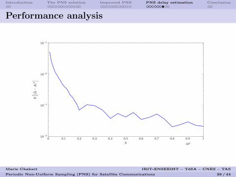
Performance analysis
0 0.1 0.2 0.3 0.4 0.5 0.6 0.7 0.8 0.9 1
·104
10−8
10−7
10−6
10−5
N
E[ |∆−
∆|2]
Marie Chabert IRIT-ENSEEIHT – TeSA – CNES – TAS
Periodic Non-Uniform Sampling (PNS) for Satellite Communications 39 / 44

Introduction The PNS solution Improved PNS PNS delay estimation Conclusion
Blind PNS delay estimation4
Principle: stationarity property
Property: wide sense stationarity of the reconstructed signal
X(∆) = {X(∆)(t), t ∈ R} if and only if ∆ = ∆. In particular:
P (∆)(tm) = E
[∣∣∣X(∆) (tm)∣∣∣2], tm =
m
M + 1, m = 1, ...,M
independent of tm.
Strategy: estimation of the reconstructed signal power P (∆)(tm)for m = 1, ...,M for different values of ∆:
P (∆)(tm) =1
N
N2∑
n=−N2
∣∣∣X(∆) (n+ tm)∣∣∣2
, m = 1, ...,M.
4J.-A. Vernhes et al. “Estimation du retard en echantillonnage periodique nonuniforme - Application aux CAN entrelaces desynchronises”. In: GRETSI 2015.
Marie Chabert IRIT-ENSEEIHT – TeSA – CNES – TAS
Periodic Non-Uniform Sampling (PNS) for Satellite Communications 40 / 44

Introduction The PNS solution Improved PNS PNS delay estimation Conclusion
Performance analysis
0.17 0.18 0.19 0.2 0.21 ∆ 0.24 0.25 0.26 0.27 0.28 0.29 0.3 0.31 0.32 0.3310−1
100
101
102
103
∆
P(∆
)m
(a) Estimated power at differenttimes tm
0.17 0.18 0.19 0.2 0.21 ∆ 0.24 0.25 0.26 0.27 0.28 0.29 0.3 0.31 0.32 0.3310−4
10−3
10−2
10−1
100
101
102
103
104
105
∆
(b) Variance of the estimatedpower
Figure: Blind estimation principle
Marie Chabert IRIT-ENSEEIHT – TeSA – CNES – TAS
Periodic Non-Uniform Sampling (PNS) for Satellite Communications 41 / 44

Introduction The PNS solution Improved PNS PNS delay estimation Conclusion
Outline
1 IntroductionProblem formulationProposed approach
2 The PNS solutionSignal modelSampling frequency requirementsPNS sampling scheme and reconstruction formulasPractical sampling device: the TI-ADCs
3 Improved PNSPrincipleConvergence speed improvementSelective reconstruction with interference cancelationAnalytic signal reconstruction
4 PNS delay estimationPNS delay estimation with a learning sequenceBlind PNS delay estimation
5 Conclusion
Marie Chabert IRIT-ENSEEIHT – TeSA – CNES – TAS
Periodic Non-Uniform Sampling (PNS) for Satellite Communications 42 / 44

Introduction The PNS solution Improved PNS PNS delay estimation Conclusion
Conclusion
Contributions
PNS as an alternative sampling scheme proposed for TI-ADCs.
Additional functionalities for telecommunications:
improved convergence speeda,selective reconstruction with interference rejectionb,analytical signal reconstructionc.
Estimation of the desynchronisation:
from a learning sequenced, blindlye.
aM. Chabert and B. Lacaze. “Fast convergence reconstruction formulas for periodicnonuniform sampling of order 2”. In: IEEE ICASSP 2012.
bJ.-A. Vernhes, M. Chabert, and B. Lacaze. “Conversion Numerique-Analogiqueselective d’un signal passe-bande soumis a des interferences”. In: GRETSI 2013.
cJ.-A. Vernhes et al. “Selective Analytic Signal Construction From A Non-UniformlySampled Bandpass Signal”. In: IEEE ICASSP 2014.
dJ.-A. Vernhes et al. “Adaptive Estimation and Compensation of the Time Delay ina Periodic Non-uniform Sampling Scheme”. In: SampTA 2015.
eJ.-A. Vernhes et al. “Estimation du retard en echantillonnage periodique nonuniforme - Application aux CAN entrelaces desynchronises”. In: GRETSI 2015.
Marie Chabert IRIT-ENSEEIHT – TeSA – CNES – TAS
Periodic Non-Uniform Sampling (PNS) for Satellite Communications 43 / 44

Introduction The PNS solution Improved PNS PNS delay estimation Conclusion
Thanks for your attention
Questions?
Marie Chabert IRIT-ENSEEIHT – TeSA – CNES – TAS
Periodic Non-Uniform Sampling (PNS) for Satellite Communications 44 / 44