2014 bsee domestic and international … · during pre-commissioning operations . ... internal...
TRANSCRIPT

API 17TR11: Pressure Effects on Subsea Hardware During Pressure Testing in Deep Water (In Ballot) - Frans Kopp: Senior Principal Advisor Pipelines – Shell
International E&P API 17TR12: Consideration of External Pressure in the Design and Pressure Rating of Subsea Equipment (In Working Group) - Man Pham: Codes and Standards Engineer - BP - Chris Johnson: Director of Engineering - NOV
2014 BSEE Domestic and International Standards Workshop

API 17TR11: Pressure Effects on Subsea Hardware During Pressure Testing in Deep Water Related Report: Formulating Guidance on Hydrotesting Deepwater Oil and Gas Pipelines – Stress Engineering Report to BSEE, Jan 31, 2013 and planned OTC Paper

The Main Challenges • Lack of Common Definitions and understanding of
Pressure Terms (MAOP, MSP, RWP, etc.) – Need to get regulators, pipeline-flowline and subsea hardware community on the same page.
• Simple design, without considerations of effect of internal and external hydrostatic fluid head, won’t work in deep water.
• Subsea hardware providers need to have a better understanding of magnitude of hydrostatic test pressure applied during subsea systems hydrostatic tests (this pressure may exceed RWP and approach or even exceed 1.5 RWP)

Definitions • RWP – Rated Working Pressure of subsea hardware components (per API
6A & 17D specifications) – Typically applies to Valves, Flanges, Hubs, Other End Connectors,
Fittings, etc – Interpreted by API to mean the “absolute pressure” of the fluid
contained within the component (Ref: API 6A: “rated working pressure - maximum internal pressure that the equipment is designed to contain and/or control)
– Introduction of new terms in API 17TR11: RWPA(Absolute) and RWPD (Differential)
• MAOP - Maximum Allowable Operating Pressure of the subsea flowline system (per pipeline code 30 CFR 250 and NTL 2009-G28)
• Po – External pressure • Pd – Differential Design Pressure as per API RP 1111 (difference between
internal and external pressure) • MSP – Maximum Source Pressure (internal)

API 17TR11: Pressure Effects on Subsea Hardware During Pressure Testing in Deep Water
• Originated in industry workgroup started in 2011 to address effects of subsea systems hydrostatic test (via deepwater riser and flowline) on subsea hardware.
• Subsea flowlines are typically hydrostatically pressure tested to 1.25 X MAOP during pre-commissioning operations .
• For flowline systems connected with risers to a floating host, and no means to isolate the riser from the flowline, the test pressure is applied at top of riser – Thus, absolute pressure (PSIA) inside flowline on seabed is increased by the seawater head pressure (inside pressure = 1.25 x MAOP + ambient seawater pressure Po)
• BSEE does not allow for the concept of variable design pressure in a flowline/riser system (one cannot consider the density of produced fluid/gas in a production flowline/riser). Therefore, for production flowlines the MAOP is generally required to be constant throughout the system and equal to the Wellhead shut-in tubing pressure (WHSITP). See also NTL 2009-G28.
• Net result is that in most cases, subsea equipment will be exposed to an internal test pressure equal to 1.25 MAOP + Po. This internal test pressure may exceed the test pressure the subsea equipment was subjected to as part of onshore shop testing or other FAT.

• 5 Cases and Discussion and Cautionary Comments for Each Case
Case Internal Subsea System Hydrotest Pressure Rating
1 At or below 1.0*RWPA (and thus below 1.0*RWPD) of the hardware components
2 Greater than 1.0*RWPA, but not above 1.0*RWPD
3 Greater than 1.0*RWPD (thus greater than 1.0*RWPA), but not above 1.5*RWPA
4 Greater than 1.5*RWPA, but not above 1.5*RWPD (or 1.25*MAOPD )
5 Greater than 1.5*RWPD
API 17TR11: Pressure Effects on Subsea Hardware During Pressure Testing in Deep Water

Example (Cases 3 and 4) • Production Flowline MSP = 12,500 psi at manifold • Water Depth = 9,000 ft (Po = 4,000 psi) • Subsea equipment RWP = 15,000 psi • MAOP as per 30 CFR 250 and NTL 2009-G28 = 12,500 psi • Flowline connected with SCR to FPS • Surface Minimum required test pressure = 1.25 MAOP = 15,625 psi • Fabrication Yard Internal Test Pressure likely to be 15,625 psi • Internal Test Pressure at Subsea Manifold = 15,625 + 4,000 = 19,625
psi = 1.30 x RWP: > 1.25 RWP but less than 1.5 RWP Is this OK?
• Same situation but MAOP = 14,500 psi. • Internal Test Pressure at Manifold is now 22,125 psi = 1.48 RWP
Is this OK?

API 17TR12: Consideration of External Pressure in the Design and Pressure Rating of Subsea Equipment

Notes (to flow chart): 1. To identify equipment / component / sub-
component category due to presence of external pressure:
a) pressure-containing; b) pressure-containing with trapped voids; or c) pressure-controlling.
2. DAWP: Depth Adjusted Working Pressure (psia)
3. SWD: Specified Water Depth (ft)
4. DWP: Differential Working Pressure (psig)
5. DWP = Max Upstream Pressure – Min. Downstream Pressure, on the pressure-controlling element, where the “Max. Upstream Pressure” can be the calculated DAWP
6. DWP < API RWP
API 17TR12 Design Assessment Flow Chart

API 17TR12 Design Assessment Flow Chart
• Thorough understanding of system/ equipment operational and functional characteristics
• Perform hazard identifications / risk assessment
• Identify equipment category: a) pressure-containing; b) pressure-containing with trapped voids; c) pressure-controlling.

API 17TR12 Design Assessment Flow Chart
• Finite element analysis (FEA) of Case 1 - 3
• von Mises Equivalent (VME) stress should be used as it is the more accurate predictor of stress states
• Additional verifications for protection against: Local failure / Localized stress
concentrations Ratcheting effects
• FEA results (stresses) shall comply with the applicable governing design specifications

API 17TR12 Design Assessment Flow Chart
• Test in hyperbaric chamber or simulate external pressure with test fixtures
• For larger components, where hyperbaric testing is not practical, validation of FEA is allowed through ASME V&V 10-2006, Guide for Verification and Validation in Computational Solid Mechanics
• Factory Acceptance Testing (FAT) in accordance with governing product specifications

API 17TR12 – FEA Example

Total number of nodes: 446,850; Total number of elements: 304,200 quadratic tetrahedral elements of type C3D10
Mesh Density

Loads & BC’s
LC1: Pi=15,000 psi Po=0 psi
LC2: Pi=20,000 psi Po=5,000 psi
LC3: Pi=18,000 psi Po=3,000 psi
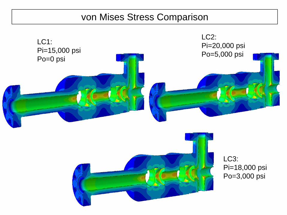
von Mises Stress Comparison
LC3: Pi=18,000 psi Po=3,000 psi
LC1: Pi=15,000 psi Po=0 psi
LC2: Pi=20,000 psi Po=5,000 psi

von Mises Stress Comparison
LC3: Pi=18,000 psi Po=3,000 psi
LC1: Pi=15,000 psi Po=0 psi
LC2: Pi=20,000 psi Po=5,000 psi

Stress Linearization

Stresses Comparison Results For All Nodes