2013 smart fortwo coupe and cabriolet owner and … in this operator’s manual might differ from...
TRANSCRIPT

>> Operator’s Manual.smart fortwo coupé and smart fortwo cabriolet
É4515848683WËÍ
4515848683
Order
no.6522
0058
13Partno.45158486
83EditionB2013
www.smart.com smart - A Daimler brand Operator’sManualsmartfortwo
coupéandsmartfortwo
cabriolet

Service and Literature
Your authorized smart center has trainedtechnicians and Genuine smart Parts toservice your vehicle properly.
For expert advice and quality service,contact an authorized smart center.
For further information you can find us onthe smart web-site www.smartusa.com (USAonly) or www.thesmart.ca (Canada only).
G WARNING
To help avoid personal injury, be extremelycareful when performing any service workor repairs. Improper or incomplete serviceor the use of incorrect or inappropriateparts or materials may damage the vehicleor its equipment, which may in turn resultin personal injury.
If you have any questions about carrying outany type of service, turn to the advice of anauthorized smart center.
We reserve the right to make changes indesign and equipment.
Therefore, information, illustrations anddescriptions in this Operator’s Manualmight differ from your vehicle.
Reprinting, translation and copying, evenof excerpts, is not permitted without ourprior authorization in writing.
Symbols
Trademarks®:
RBluetooth® is a registered trademark ofBluetooth SIG Inc.RESP® is a registered trademark ofDaimler.RiPod® is a registered trademark of AppleInc., registered in the U.S.A. and othercountries.
The following symbols are found in thisOperator’s Manual:
* Optional equipment is identified withan asterisk. Since standard equipmentvaries between models, thedescriptions and illustrations in thisOperator’s Manual may differ slightlyfrom the actual equipment of yourvehicle.
G WARNING
Warning notices draw your attention tohazards that may endanger your health orlife, or the health or life of others.
! Highlights hazards that may result indamage to your vehicle.
i Helpful hints or further informationyou may find useful.
X This symbol points toinstructions for you to follow.
X A number of these symbolsappearing in successionindicates a multiple-stepprocedure.
Y page This symbol tells you where youcan find additional informationon a topic within this Operator’sManual.
YY This continuation symbol marks awarning or procedure which iscontinued on the next page.
DisplayDisplay Text in displays, such as thecontrol system displays, areprinted in the type shown here.
As at 10.02.2012

Let the fun begin!
Take a moment to familiarize yourself with
your smart fortwo coupé or smart fortwo
cabriolet and read through the Operator’s
Manual before driving. This will ensure
you get more fun out of your vehicle - and
avoid danger to yourself and others.
This Operator’s Manual contains very
important information about how to safely
and effectively operate the vehicle. It is
important to note that this is a unique
vehicle. It is obviously smaller than most
vehicles on the road and, for this reason,
it can provide both unique experiences and
special responsibilities. It is extremely
important that you read this entire Manual
and that you familiarize yourself with how
the vehicle works. Some of the features may
be different from the features on other
compact passenger vehicles. Should you
have any questions about the vehicle and
how to safely operate its features, please
use common sense and contact smart dealer
representatives, who are available to help
you.
smart is a vehicle manufactured by
Daimler, distributed in the United States
by smart USA Distributor LLC., and in
Canada by Mercedes-Benz Canada, and sold
and serviced by independent, authorized
smart centers.
Because of this vehicle’s unique
characteristics, we strongly recommend
that you service and maintain the vehicle
only at authorized smart service
facilities. A list of service facilities is
available by calling smart Customer
Assistance representatives at:
1‑800‑762‑7887 (in the USA)
1‑877‑627‑8004 (in Canada)
Although we cannot prevent you from
servicing the vehicle at facilities other
than smart authorized facilities, this is
not advisable.
Optional extras are identified with an
asterisk*. The equipment in your vehicle
may vary depending on the model, version
and availability. smart is constantly
bringing its vehicles up to the very latest
state of the art and reserves the right to
modify them in form, equipment and
engineering.
Should you find that a particular feature in
this manual is important to your decision
to purchase the vehicle, we recommend that
you personally check the vehicle to ensure
that this feature has been installed before
buying the vehicle.
The Operator’s Manual, Quick Guide and
Scheduled Maintenance Guide/Warranty
Booklet (USA only) or Service/Warranty
Booklet (Canada only) belong to the
vehicle. You should always keep these
documents in the vehicle and make sure you
pass them on to the next owner if and when
you sell your smart.
Please contact an authorized smart center
if you have any further questions.
The Technical Documentation team at
Daimler wishes you many happy hours at the
wheel.
4515848683 É4515848683WËÍ


Index ............................................ 4
Introduction ................................. 13
At a glance .................................... 19
Safety .......................................... 29
Controls ....................................... 51
Operation .................................... 115
Practical hints ............................. 157
Technical data ............................. 211
Contents 3

A
ABS (Antilock Brake System) ............. 46
Indicator lamp ........................ 163
Accessory weight .......................... 140
Accidents
Air bags .................................. 33
Additives
Engine oil .............................. 221
Gasoline ................................ 222
Address change .............................. 15
Air bags ....................................... 33
Children .................................. 33
Front, driver and passenger ......... 36
Front, passenger ....................... 36
Head-thorax ............................. 37
Knee bag .................................. 37
Passenger front air bag off
indicator lamp ..................... 27, 41
Safety guidelines ...................... 35
SRS indicator lamp ................... 166
Thorax-pelvis .......................... 38
Window curtain ......................... 38
Air conditioning
see HVAC ................................ 102
Air conditioning refrigerant .......... 221
Air pressure
see Tire inflation pressure
Air pressure (tires) ....................... 141
Air vents ..................................... 104
Alarm system
see Anti-theft systems
Ambient lighting* .......................... 68
Anticorrosion/antifreeze ............... 223
Antiglare, Interior rear view
mirror ......................................... 62
Antilock Brake System
see ABS
Anti-theft systems ......................... 48
Anti-theft warning system ........... 48
Electronic immobilizer .............. 48
Interior motion sensor ............... 49
Tow-away alarm ......................... 49
Aquaplaning
see Hydroplaning
Armrest ........................................ 59
Aspect ratio (tires) ....................... 141
Audio system ................................. 98
Basic ...................................... 99
Navigation/multimedia .............. 99
Automatic headlamp mode ................ 65
Automatic locking .......................... 53
Automatic transmission ................... 81
Display message ....................... 159
Driving tips ............................. 83
Emergency operation (limp-
home mode) ............................... 85
Gear selector lever .................... 81
Gear selector lever positions ...... 82
Gearshift pattern ...................... 81
Hill-start assist system .............. 83
Manual gearshifting .................. 84
Shifting procedure .................... 82
Auxiliary instruments
Cockpit clock ............................ 91
Tachometer ............................... 91
AUX socket .................................... 99
B
Backrest
see Seats
Backup lamp ................................. 180
Bar (air pressure unit) ................... 141
Battery
Charging ................................ 196
Indicator lamp ........................ 168
Jump starting .......................... 199
Removing and installing ............ 196
Battery (key)
Replacing the transmitter
battery ................................... 177
Bead (tire) ................................... 141
Brake fluid .................................. 124
Checking ................................ 124
Brake lamp .................................. 180
Brake pedal .................................. 80
Brakes ........................................ 145
Parking brake ........................... 79
Warning lamp .......................... 164
Break-in period ........................... 116
Bulbs
Front ..................................... 179
Rear ...................................... 180
Replacing ............................... 178
4 Index

C
CAC (Customer Assistance Center) ...... 16
California retail buyers and
lessees, important notice for ........... 14
Can holder
see Cup holder
Cargo compartment cover blind ........ 107
Catalytic converter ....................... 147
CD player ..................................... 98
Center console .............................. 26
Central locking
Automatic ................................ 53
Locking/unlocking from inside .... 54
Certification label ....................... 214
Children in the vehicle ................... 42
Air bags .................................. 33
Indicator lamp, passenger front
air bag off .......................... 41, 173
Infant and child restraint
systems ................................... 43
OCS (Occupant Classification
System) ................................... 39
Safety notes ............................. 42
Tether anchorage points ............. 44
Child safety
see Children in the vehicle
Cigarette lighter .......................... 114
Climate control
see HVAC ................................ 102
Clock ........................................... 88
Cockpit ........................................ 20
Coin holder ................................. 110
Cold tire inflation pressure ............ 141
Combination switch ........................ 66
Control system
Consumption menu ..................... 95
Control lever ............................ 92
Introduction ............................ 92
Menus and submenus ................... 94
Messages menu .......................... 96
Multifunction display ................ 92
Odometer menu .......................... 94
Reset menu ............................... 95
Settings menu ........................... 96
Start menu ............................... 95
Time menu ................................ 97
Coolant
Anticorrosion/antifreeze .......... 223
Capacities ............................. 220
Checking level ......................... 122
Temperature warning lamp ......... 170
Coolant temperature ...................... 151
Cruise control ............................. 100
Cup holder ................................... 107
Curb weight ................................. 141
Customer Assistance Center (CAC) ...... 16
D
Dashboard
see Instrument cluster
Data recording ............................... 17
Daytime running lamp mode .............. 66
Deep water
see Standing water
Defroster
Rear window ............................ 106
Windshield ............................. 106
Department of Transportation
see DOT
Dimensions (vehicle)
see Vehicle specification
Direction of rotation (tires) ........... 134
Display messages
Automatic transmission ............. 159
Electronic immobilizer ............. 159
Door control panel ......................... 27
Door handles ................................. 27
Doors
Locking/unlocking from outside ... 53
Opening from inside .................. 54DOT (Department of
Transportation) ...................... 139, 141
Drinking and driving ..................... 144
Driving
Abroad ................................... 151
Coolant temperature .................. 151
Hydroplaning .......................... 148
Instructions ....................... 77, 144
In winter ................................ 149
Safety systems .......................... 46
Through standing water ............. 149
Tips, automatic transmission ...... 83
Index 5

Driving and parking
Safety notes .............................. 77
Driving safety systems .................... 46
ABS ........................................ 46
ESP® ....................................... 47
Hydraulic brake assistant ........... 48
E
Electrical system
Improper work on or
modifications ........................... 15
Power outlet ............................ 114
Electronic immobilizer .................. 48
Display message ....................... 159
Electronic Power Steering
see EPS
Electronic Stability Program
see ESP®
Emergency, in case of
Hazard warning flasher .......... 48, 69
Roadside Assistance .................. 14Emergency operation (limp-home
mode) .......................................... 85
Emergency Tensioning Device
see ETD
Emission control .......................... 150
Information label ..................... 213
System warranties ...................... 13
Engine
Break-in recommendations ......... 116
Compartment ............................ 117
Compartment cover .................... 117
Electronics ............................. 212
Malfunction indicator lamp ........ 171
Number .................................. 214
Starting .................................. 77
Turning off .............................. 81
Engine coolant
see Coolant
Engine oil
Adding ................................... 119
Additives ............................... 221
Checking level ......................... 118
Consumption ............................ 118
Oil dipstick ............................ 119
EPS (Electronic Power Steering)
Warning lamp ........................... 167
ESP® (Electronic Stability Program) ... 47
Warning lamp ........................... 167
ETD (Emergency Tensioning Device) . . . 33
Safety guidelines ...................... 35
Exterior lamp switch ...................... 64
Exterior lighting
Overview ................................ 179
Exterior rear view mirrors .............. 61
F
First-aid kit ............................... 158
Flat tire ..................................... 186
Fluids
Capacities ............................. 220
Engine coolant ........................ 220
Engine oil .............................. 220
Fog lamps ................................ 68, 179
Front air bags
see Air bags
Front compartment ........................ 120
Front lamps
Overview ................................ 179
Fuel ........................................... 146
Additives ............................... 222
Capacity, fuel tank ................... 220
Fuel filler flap and cap ............. 116
Fuel level display ..................... 89
Premium unleaded
gasoline ..................... 117, 220, 221
Refueling ............................... 116
Requirements .......................... 222
Fuel cap
Indicator lamp ......................... 170
Fuel filler flap ............................. 116
Fuel level display .......................... 89
Fuel tank
Capacity ................................ 220
Fuel filler flap and cap ............. 116
Refueling ............................... 116
Fuse chart ................................... 208
Fuses ......................................... 205
G
Gasoline
see Fuel
GAWR (Gross Axle Weight Rating) ...... 141
6 Index

Gear selector lever ......................... 81
Transmission positions .............. 82
Global locking/unlocking ................ 53
Glove box .................................... 110
Gross Axle Weight Rating
see GAWR
Gross Vehicle Weight
see GVW
Gross Vehicle Weight Rating
see GVWR
GVW (Gross Vehicle Weight) ............. 141
GVWR (Gross Vehicle Weight Rating) . . 141
H
Halogen headlamps
see Headlamps
Hazard warning flasher ................... 69
Headlamps
Automatic headlamp mode ............ 65
Daytime running lamp mode ......... 66
High-beam flasher ..................... 67
High-beam headlamps ................. 67
Low-beam headlamps .................. 65
Switch ..................................... 64
Head-thorax air bags ...................... 37
Heated exterior rear view mirrors ..... 62
Heated seats .................................. 60
Heating
see HVAC ................................ 102
Height adjustment
Seats ...................................... 59
High-beam flasher .......................... 67
High-beam headlamps ................ 67, 179
Indicator lamp ........................ 169
High-mounted brake lamp ............... 180
Hill-start assist system .................. 83
HVAC (Heating, Ventilation, Air
Conditioning) .............................. 102
Air distribution ...................... 105
Air recirculation ..................... 107
Air vents ................................ 104
Air volume .............................. 106
Defrosting .............................. 106
Rear window defroster ............... 106
Temperature ............................ 104
Hydraulic brake assistant ................ 48
Hydroplaning ............................... 148
I
Identification labels .................... 213
Identification number, vehicle
(VIN) .......................................... 214
Infant and child restraint systems
see Children in the vehicle
Inflation pressure
see Tires, Inflation pressure
Inside door handle ......................... 54
Instrument cluster ..................... 21, 23
Illumination ............................ 92
Lamps, indicator and warning ..... 162
Instrument panel
see Instrument cluster
Instruments and controls
see Cockpit
Interior motion sensor .................... 49
Interior rear view mirror ................ 62
Interior storage spaces
see Storage compartments
Intermittent wiping
Rear window wiper ..................... 71
Windshield wipers ..................... 70
J
Jump-starting .............................. 199
K
Key ............................................. 52
Loss of ................................... 174
Replacing the transmitter
battery ................................... 177
Kilopascal (air pressure unit) ......... 141
Knee bag ....................................... 37
L
Labels ........................................ 213
Emission control information ..... 213
Lamps, exterior
Exterior lamp switch .................. 64
Switching on/off ....................... 64
Index 7

Lamps, indicator and warning
ABS ....................................... 163
Battery ................................... 168
Brakes ................................... 164
Coolant temperature ................. 170
Engine malfunction ................... 171
EPS ........................................ 167
ESP® ...................................... 167
Fog lamps ................................ 68
Fuel cap ................................. 170
High-beam headlamps ............... 169
Low-beam headlamps ................. 169
Low tire pressure/TPMS
malfunction telltale ................. 172
Oil pressure ............................ 171
Overview (kilometers) ................ 24
Overview (miles) ....................... 22
Passenger front air bag off .... 36, 173
Seat belt telltale ..................... 165
SRS ........................................ 166
Turn signals ............................ 169
License plate lamps ....................... 180
Lighter
see Cigarette lighter
Lighting ...................................... 64
Ambient lighting* ..................... 68
Coming home function ................. 67
Daytime running lamp mode ......... 66
Exterior .................................. 64
Interior .................................. 69
Loading
see Vehicle loading
Locking the vehicle ........................ 52
Manually ................................. 176
Loss of
Key ........................................ 174
Service and Warranty
Information booklet .................. 212
Low-beam headlamps ................. 65, 179
Exterior lamp switch .................. 64
Indicator lamp ........................ 169
Switching on ............................ 65
M
Main odometer display .................... 87
Maintenance .................................. 14
Service interval display ............. 90
Malfunction
Electronic immobilizer ............. 159
Shifting system ....................... 159Manual headlamp mode (Low-beam
headlamps) ................................... 65
Maximum loaded vehicle weight ....... 141
Maximum load rating (tires) ............ 141
Maximum permissible tire
inflation pressure ........................ 141
Mirrors
Exterior rear view mirrors .......... 61
Interior rear view mirror ........... 62
MON (Motor Octane Number) ............. 222
Motor Octane Number
see MON
Multifunction display ..................... 86
N
Normal occupant weight ................. 142
Number, vehicle identification
(VIN) .......................................... 214
O
Occupant Classification System
see OCS (Occupant
Classification System)
Occupant distribution ................... 142
Occupant safety
Air bags .................................. 33
Children and air bags ................ 33
Children in the vehicle .............. 42
Infant and child restraint
systems ................................... 43
Introduction ............................ 30
OCS (Occupant Classification
System) ................................... 39
Passenger front air bag off
indicator lamp ......................... 39
Seat belts ............................ 31, 35
SRS indicator lamp, malfunction . 166OCS (Occupant Classification
System) ........................................ 39
Self-test ................................. 42
Oil
see Engine oil
8 Index
Oil level
see Engine oil, Checking level
On-board Diagnostics Socket (OBD) ... 213
Operating safety ............................ 15
Outside temperature display ............ 88
Overhead control panel .................... 27
P
Paintwork care ............................. 155
Panic alarm .................................. 45
Parcel nets ............................. 107, 111
Parking ........................................ 79
Parking brake ................................ 79
Parking lamps .............................. 179
Parts service ............................... 212
PASS AIR BAG OFF indicator lamp
see Passenger front air bag off
indicator lamp
Passenger front air bag ................... 36
Passenger front air bag off
indicator lamp .................... 27, 36, 173
Passenger safety
see Occupant safety
Passenger seat ............................... 60
Pedals ........................................ 144
Power assistance .......................... 144
Power outlet ................................. 114
Power washer ............................... 154
Practical hints
Battery .................................. 196
Display messages ..................... 158
Flat tire ................................. 186
Fuses ..................................... 205
Jump starting .......................... 199
Replacing bulbs ....................... 178
Replacing transmitter battery .. . . 177
Replacing wiper blades ............. 184
Towing ................................... 202
Unlocking/locking manually ....... 176
Warning and indicator
lamps ............................... 162, 173
What to do if ............................ 162
Where will I find...? ................. 158
Premium unleaded gasoline ............ 222
Problems with your vehicle .............. 16
Product information ....................... 13
Production options weight .............. 142
PSI (air pressure unit) ................... 142
R
Radio .......................................... 98
Radio transmitters ........................ 150
Rain-light sensor .......................... 70
Rear lamps
Overview ................................ 180
Rear window defroster ................... 106
Rear window wiper/washer ................ 71
Replacing wiper blade .............. 184Recommended tire inflation
pressure ................................ 125, 142
Refrigerant, air conditioning ......... 221
Refueling .................................... 116
Remote control
see Key
Replacing bulbs ............................ 178
Reporting safety defects .................. 16
Research Octane Number
see RON
Reserve fuel indicator .................... 91
Restraint systems
see Occupant safety
Rims ..................................... 142, 216
Roadside Assistance ....................... 14
RON (Research Octane Number) ......... 222
Roof
see Soft top system
S
Safety
Driving safety systems ............... 46
Occupant safety ......................... 30
Reporting defects ...................... 16
Safety belts
see Seat belts
Seat belt force limiter .................... 33
Seat belts ..................................... 31
Children in the vehicle .............. 42
Fastening ................................ 62
Proper use of ............................ 31
Safety guidelines ...................... 35
Safety notes .............................. 31
Telltale ................................. 165
Index 9

Seating capacity ........................... 131
Seats ........................................... 58
Adjustment ............................... 59
Armrest ................................... 59
Heating ................................... 60
Passenger seat .......................... 60
Self-test
OCS (Occupant Classification
System) ................................... 42
SRS ......................................... 30
Service
see Maintenance
Service, parts .............................. 212
Service and warranty
Booklet .................................. 212
Service flap ................................ 120
Service interval display ................. 90
Service life (tires) ....................... 134
Side marker lamps ......................... 179
Sidewall (tires) ............................ 142
Side windows
Operation ................................ 76
Signs and labels ........................... 213
smart surround sound system ........... 100
Snow chains ................................. 143
Snow tires
see Winter tires
Soft top system ............................... 71
Cleaning the soft top fabric ....... 155
Locking rear soft top manually .... 177
Mounting the side rails .............. 75
Opening and closing the rear
soft top ............................... 56, 73
Opening and closing the
retractable soft top ............... 56, 72
Removing the side rails .............. 74
Storing the side rails ................ 75
Sound package .............................. 100
SRS (Supplemental Restraint
System)
Indicator lamp ........................ 166
Standing water, driving through ...... 149
Starter switch positions .................. 57
Starting the engine ........................ 77
Status indicator ............................ 89
Steering wheel gearshift control ...... 25
Storage compartments .................... 109
Coin holder ............................. 110
Door pockets ............................ 110
Drawer .................................... 111
Glove box ................................ 110
in the tailgate ......................... 111
Parcel nets .............................. 111
Storage tray in center console ..... 111
Storage trays next to steering
wheel ..................................... 110
Storing tires ............................... 135
Sun screen ................................... 113
Sun visors ................................... 113
T
Tailgate
Closing ............................... 55, 57
Opening .............................. 54, 56
Tail lamps ................................... 180
Technical data
Air conditioning refrigerant ..... 221
Brake fluid ............................. 221
Coolant .................................. 223
Engine oil additives ................. 221
Engine oils ............................. 220
Fuel requirements .................... 222
Gasoline additives ................... 222
Identification labels ................ 213
Premium unleaded gasoline ........ 221
Rims and tires ......................... 216
Service fluids and capacities ..... 218
Vehicle specification (model
BRABUS) ................................. 216
Vehicle specification (model
passion) ................................. 215
Vehicle specification (model
pure) ..................................... 215
Windshield/rear window washer
system ............................. 220, 222
Technical data (dimensions)
see Vehicle specification
Technical data (weights)
see Vehicle specification
Temperature
Coolant .................................. 151
Interior temperature ................ 104
Outside ................................... 88
10 Index
Tether anchorage points
see Children in the vehicle
Thorax-pelvis side air bags ............. 38
Tightening torque
Wheels ................................... 136TIN (Tire Identification
Number) ................................ 139, 142
Tire and Loading Information
placard ....................................... 130
Tire and loading terminology .......... 140
Tire Identification Number
see TIN
Tire inflation pressure
Checking ................................ 127
Important notes on .................... 126
Placard on driver’s door B-
pillar .................................... 130
Tire labeling ............................... 136
Tire load rating ........................... 142
Tire ply composition and material
used ........................................... 142
Tire Pressure Monitoring System
(TPMS) ........................................ 128
Tire repair kit ....................... 158, 186
Tires .................................... 124, 216
Air pressure ........................... 125
Care and maintenance ............... 134
Cleaning ................................ 135
Direction of rotation, spinning . . 134
Driving instructions ................. 147
Flat tire ................................. 186
Important notes on tire
inflation pressure .................... 126
Inflation pressure .............. 126, 127
Information placard ................. 130
Inspection .............................. 134
Labeling ................................ 136
Load rating ............................. 142
Ply composition and material
used ...................................... 142
Problems under-/overinflation ... 126
Retreads ................................. 124
Rims and tires (technical data) ... 216
Rotation ................................. 136
Service life ............................ 134
Sizes ..................................... 216
Snow chains ............................ 143
Speed rating ................ 138, 142, 148
Storing .................................. 135
Temperature ...................... 126, 136
Terminology ............................ 140
Tire Identification Number . . 139, 142
Tire Pressure Monitoring
System (TPMS) .......................... 128
Traction ..................... 135, 142, 148
Tread ..................................... 142
Tread depth ....................... 134, 143
Treadwear indicators .......... 134, 143
Vehicle maximum load on ........... 143
Wheel change ........................... 194
Winter tires ...................... 143, 216
Tire speed rating .................... 138, 142
Top tether
see Children in the vehicle
Total load limit ........................... 142
Tow-away alarm ............................. 49
Towing ....................................... 202
Traction ................................ 142, 148
Transmission
see Automatic transmission
Transmission position indicator ...... 87
Transmitting power values .............. 212
Traveling abroad .......................... 151
Tread (tires) ................................ 142
Tread depth (tires) .................. 134, 143
Treadwear indicators (tires) ..... 134, 143
Trip odometer, resetting ................. 90
Turning off the engine .................... 81
Turn signal lamps ......................... 179
Turn signals .................................. 67
Indicator lamps ....................... 169
U
Uniform Tire Quality Grading
Standards .............................. 135, 143
Unleaded gasoline, premium ........... 221
Unlocking the vehicle ..................... 52
Manually ................................. 176
USB socket .................................... 99
Index 11

V
Vehicle
Bulbs ..................................... 178
Care ...................................... 151
Identification Number (VIN) ....... 214
Locking/unlocking .................... 52
Modifications and alterations,
Operating safety ....................... 15
Towing ................................... 202
Unlocking/locking manually ....... 176
Vehicle dimensions
see Vehicle specificationVehicle Identification Number
(VIN) .......................................... 214
Vehicle lighting ............................ 64
Vehicle loading
Instructions ............................ 112
Load limit .............................. 132
Roof rack ................................ 112
Terminology ............................ 140
Vehicle maximum load on the tire .... 143
Vehicle specification
Model BRABUS .......................... 216
Model passion ......................... 215
Model pure .............................. 215
Vehicle washing
see Vehicle care
Vehicle weights
see Vehicle specification
Ventilation
see HVAC ................................ 102
W
Warning signals
Anti-theft warning system .......... 175
Brake pads .............................. 176
Door ...................................... 175
Parking .................................. 176
Seat belt reminder system .... 165, 175
Warranty coverage ......................... 212
Warranty information ...................... 13
Washer fluid
Mixing ratio ........................... 222
Refilling ............................... 123
Wiping .................................... 71
Washer jet nozzles ......................... 186
Washing the vehicle ....................... 151
Weights (vehicle)
see Vehicle specification
Wheel change ............................... 194
Wheel cover ................................. 194
Wheels, sizes ............................... 216
Wheels, Tires and .......................... 124
Where will I find...?
First-aid kit ........................... 158
Tire repair kit ........................ 158
Window curtain air bags .................. 38
Windshield
Washer fluid ....................... 71, 222
Wipers .................................... 70
Windshield wipers .......................... 70
Adjusting washer jet nozzles ...... 186
Rain-light sensor ...................... 70
Replacing wiper blades ............. 184
Winter driving
Driving instructions ................ 149
Snow chains ............................ 143
Tires ..................................... 143
Winter tires ........................... 143, 216
12 Index

Product information
We recommend using Genuine smart Parts as
well as conversion parts and accessories
explicitly approved by smart for your
vehicle model.
We have tested these parts to determine
their reliability, safety and special
suitability for smart vehicles.
We are unable to make an assessment for
other products and therefore cannot be
held responsible for them, even if in
individual cases an official approval or
authorization by governmental or other
agencies should exist. Use of such parts
and accessories could adversely affect the
safety, performance or reliability of your
vehicle. We strongly recommend that you
not use them.
Genuine smart Parts as well as conversion
parts and accessories approved by us are
available at your authorized smart center
where you will receive comprehensive
information about use and installation of
appropriate parts.
Operator’s Manual
This Operator’s Manual contains a great
deal of useful information. We urge you to
read it carefully and familiarize yourself
with the vehicle before driving.
For your own safety and longer service life
of the vehicle, we urge you to follow the
instructions and warnings contained in
this manual. Ignoring them could result in
damage to the vehicle or personal injury to
you or others. Vehicle damage caused by
failure to follow instructions is not
covered by the smart Limited Warranty.
Your vehicle may have some or all of the
equipment described in this manual.
Therefore, you may find explanations for
optional equipment not installed in your
vehicle. If you have any questions about the
operation of any equipment, your
authorized smart center will be glad to
demonstrate the proper procedures.
We continuously strive to improve our
product, and ask for your understanding
that we reserve the right to make changes
in design and equipment. Therefore,
information, illustrations and
descriptions in this Operator’s Manual
might differ from your vehicle.
Optional equipment is also described in
this manual, including operating
instructions wherever necessary. Since
they are special-order items, the
descriptions and illustrations herein may
vary slightly from the actual equipment of
your vehicle.
If there are any equipment details that are
not shown or described in this Operator’s
Manual, your authorized smart center will
be glad to inform you of correct care and
operating procedures.
The Operator’s Manual and Maintenance/
Warranty Booklet (USA only) or Service/
Warranty Booklet (Canada only) are
important documents and should be kept
with the vehicle.
Warranty information
The smart USA Warranty booklet (USA only)
or the Warranty booklet (Canada only)
contains detailed information about the
warranties covering your smart,
including:
Rsmart USA Limited Warranty (USA only)
RNew Vehicle Limited Warranty (Canada
only)
REmission System Warranty
REmission Performance Warranty
RCorrosion Warranty
RCalifornia, Connecticut, Maine,
Massachusetts, New York, Pennsylvania,
Rhode Island, and Vermont Emission
Control System Warranty
>> Introduction. 13

Rsmartmove Assistance (Canada only)
RState Warranty Enforcement Laws (Lemon
Laws, USA only)
Important notice for California retail
buyers and lessees of smart
automobiles
Under California law you may be entitled
to a replacement of your vehicle or a refund
of the purchase price or lease price, if
Daimler Vehicle Innovations USA LLC and/
or its authorized repair or service
facilities fail to fix one or more
substantial defects or malfunctions in the
vehicle that are covered by its express
warranty after a reasonable number of
repair attempts. During the period of
18 months from original delivery of the
vehicle or the accumulation of 18000 miles
(approximately 29000 km) on the odometer
of the vehicle, whichever occurs first, a
reasonable number of repair attempts is
presumed for a retail buyer or lessee if one
or more of the following occurs:
(1) the same substantial defect or
malfunction results in a condition that
is likely to cause death or serious
bodily injury if the vehicle is driven,
that defect or malfunction has been
subject to repair two or more times,
and you have directly notified Daimler
Vehicle Innovations USA LLC in
writing of the need for its repair,
(2) the same substantial defect or
malfunction of a less serious nature
than category (1) has been subject to
repair four or more times and you have
directly notified us in writing of the
need for its repair, or
(3) the vehicle is out of service by reason
of repair of the same or different
substantial defects or malfunctions
for a cumulative total of more than
30 calendar days.
Written notification should not be sent to
a dealer, it should be addressed to:
Daimler Vehicle Innovations USA LLC
One Mercedes Drive
Montvale, NJ 07645
Maintenance
The ScheduledMaintenance Guide (USA) and
Service Booklet (Canada) describes all the
necessary maintenance work which should
be performed at regular intervals. It is
important that you service your vehicle in
accordance with the prescribed
maintenance schedule. Failure to do so may
render your vehicle unsafe, it may affect
the durability of the vehicle, and it may
otherwise void the limited, express
warranty.
Always have the Scheduled Maintenance
Guide (USA) or Service Booklet (Canada)
with you when you take the vehicle to your
authorized smart center for service. The
service advisor will record each service in
the booklet for you.
Roadside Assistance
The smartmove Assistance (Canada) and
smart 1 service (USA) Program provides
factory trained technical help in the event
of a breakdown. Calls to the toll-free
Roadside Assistance number
1-800-762-7887 (in the USA)
1-877-627-8004 (in Canada)
will be answered by smart Customer
Assistance Representatives 24 hours a day,
365 days a year.
Roadside Assistance will be provided in
accordance with standard program
guidelines which include providing
service to the vehicle up to a reasonable
distance from a paved roadway. We will
make every effort to assist in a breakdown
situation, however, the accessibility of
14 >> Introduction.

your vehicle will be determined by our
authorized smart center technician or the
tow service provider on a case-by-case
basis and may be a factor in our ability to
respond.
Additional charges may be applicable for
a breakdown location determined not to be
a reasonably accessible roadside location
as determined by our authorized
technician and tow service provider.
For additional information refer to the
smart Roadside Assistance Program
brochure (USA) or the Warranty Booklet
(Canada) in your vehicle literature
portfolio.
Change of address or ownership
In the USA: If you change your address, be
sure to send in the “Information Change
Card” found in the Warranty Information
Booklet.
In Canada: If you change your address, be
sure to send in the “Change of Address
Notice” found in the Warranty Booklet, or
simply call the Customer Service at
1-800-387-0100.
Maintaining your current address
information with smart will enable us to
contact you should important new
information about the vehicle, such as
recalls, become available.
If you sell your smart, please leave all
literature with the vehicle to make it
available to the next operator.
In the USA: If you bought this vehicle used,
be sure to send in the “Information Change
Card” found in the Warranty Information
Booklet.
In Canada: If you bought this vehicle used,
be sure to send in the “Notice of Pre‑Owned
Vehicle Purchase” found in the Warranty
Booklet, or call the Customer Service at
1-800-387-0100.
Operating your vehicle outside the USA
or Canada
If you plan to operate your vehicle in
foreign countries, please be aware that:
RService facilities or replacement parts
may not be readily available.
RUnleaded gasoline for vehicles with
catalytic converters may not be
available; the use of leaded fuels will
damage the catalysts.
RGasoline may have a considerably lower
octane rating, and improper fuel can
cause engine damage.
Operating safety
G WARNING
Work improperly carried out on electronic
components and associated software could
cause them to cease functioning. Because
the vehicle’s electronic components are
interconnected, any modifications made
may produce an undesired effect on other
systems. Electronic malfunctions could
seriously impair the operating safety of
your vehicle.
See an authorized smart center for repairs
or modifications to electronic
components.
Improper work or modifications on other
vehicle systems could also have a negative
impact on the operating safety of the
vehicle.
G WARNING
Some safety systems only function while the
engine is running. You should therefore
never turn off the engine while driving.
G WARNING
Heavy blows against the vehicle underbody
or tires/wheels, for example when running
over an obstacle, road debris or a pothole,
>> Introduction. 15
Z

may cause serious damage and impair the
operating safety of your vehicle.
If you feel a sudden significant vibration
or ride disturbance, or you suspect that
damage to your vehicle has occurred, you
should turn on your hazard warning
flashers, carefully slow down, and drive
with caution to an area which is a safe
distance from the road.
Inspect the vehicle underbody and tires/
wheels for possible damage. If the vehicle
appears unsafe, have it towed to the nearest
authorized smart center or other qualified
maintenance or repair facility for further
inspection or repairs.
Proper use of the vehicle
Proper use of the vehicle requires that you
are familiar with the following
information and rules:
Rthe safety precautions in this manual
Rthe “Technical data” section in this
manual
Rtraffic rules and regulations
Rmotor vehicle laws and safety standards
G WARNING
Various warning labels are attached to your
vehicle. These warning labels are intended
to make you and others aware of various
risks. You should not remove any of these
warning labels unless explicitly
instructed to do so by information on the
label itself. Removal of any of these labels
may cause you and others to be unaware of
certain risks which may result in an
accident and/or personal injury.
Problems with your vehicle
If you should experience a problem with
your vehicle, particularly one that you
believe may affect its safe operation, we
urge you to immediately contact an
authorized smart center to have the
problem diagnosed and corrected if
required. Do not drive the vehicle if you
believe itmay not be safely operated. If the
matter is not handled to your satisfaction,
please discuss the problem with the smart
center management, or if necessary contact
us at one of the following addresses:
In the USA:
Daimler Vehicle Innovations USA LLC
One Mercedes Drive
Montvale, NJ 07645
In Canada:
Customer Relations Department
98 Vanderhoof Avenue
Mercedes-Benz Canada, Inc.
Toronto, Ontario, M4G 4C9
Reporting safety defects
For the USA only: The following text is
published as required of manufacturers
under Title 49, Code of U.S. Federal
Regulations, Part 575 pursuant to the
National Traffic and Motor Vehicle Safety
Act of 1966.
If you believe that your vehicle has a defect
which could cause a crash or could cause
injury or death, you should immediately
inform the National Highway Traffic Safety
Administration (NHTSA) in addition to
notifying Daimler Vehicle Innovations USA
LLC.
If NHTSA receives similar complaints, it
may open an investigation, and if it finds
that a safety defect exists in a group of
vehicles, it may order a recall and remedy
campaign. However, NHTSA cannot become
involved in individual problems between
you, your dealer, or Daimler Vehicle
Innovations USA LLC.
To contact NHTSA, you may call the Vehicle
Safety Hotline toll-free at 1-888-327-4236
(TTY: 1-800-424-9153); go to
16 >> Introduction.

http://www.safercar.gov ; or write to:
Administrator, NHTSA Headquarters, 1200
New Jersey Avenue, SE, West Building,
Washington, DC 20590. You can also obtain
other information about motor vehicle
safety from http://www.safercar.gov.
Vehicle data recording
Information regarding electronic
recording devices
(Including notice pursuant to California
Code § 9951)
Please note that your vehicle is equipped
with devices that can record vehicle
systems data.
This information helps, for example, to
diagnose vehicle systems after a collision
and to continuously improve vehicle
safety.
smart may access the information and share
it with others
Rfor safety research or vehicle diagnosis
purposes
Rwith the consent of the vehicle owner or
lessee
Rin response to an official request by law
enforcement or other government agency
Rfor use in dispute resolution involving
smart, its affiliates or sales/service
organization and/or
Ras otherwise required or permitted by
law
>> Introduction. 17
Z

18

>>Ataglance.
Cockpit ........................................... 20
Instrument cluster (miles) ................... 21
Instrument cluster (kilometers) ........... 23
Steering wheel gearshift control .......... 25
Center console .................................. 26
Overhead control panel ....................... 27
Door control panel ............................. 27

Cockpit
Function Page
: Exterior lamp switch 64
; Steering wheel1
= Instrument cluster 21
? Steering wheel gearshift
control 84
A Tachometer* 91
B Cockpit clock* 91
C Glove box 110
AUX/USB sockets* 100
D Overhead control panel 27
E Audio system* 98
F Center console switches 26
G Coin holder 110
Retractable soft top
switch2 73
Function Page
H Gear selector lever 81
I Starter switch 57
J Cup holder 107
K Auxiliary power outlet 114
L Storage tray* 111
M Wiper switch 70
Cruise control switch* 100
Control lever (control
system)* 92
N On-board Diagnostics
Socket (OBD) 213
O Horn
P Cruise control buttons* 100
Q Door control panel 27
R Inside door handle 54
1 Model pure only: The steering wheel in this vehicle varies from steering wheel illustrated.
2 cabriolet only.
20 Cockpit>>Ataglance.
* optional

Instrument cluster (miles)
Miles
Instrument cluster (U.S. vehicles)
Function Page
: Speedometer
; Right indicator and
warning lamp display 22
= Adjusting instrument
cluster illumination 92
Setting digital clock 88
? Multifunction display 86
Function Page
A Center indicator and
warning lamp display 22
B Selecting display for
status indicator 89
Setting digital clock 88
C Left indicator and
warning lamp display 22
Instrument cluster (miles) 21
>>Ataglance.

Indicator and warning lamps
Function Page
: M Low‑beam
headlamp indicator
lamp65,
169
; # Left turn signal
indicator lamp67,
169
= ÷ ESP® warning lamp 167
? ! Right turn signal
indicator lamp67,
169
A D EPS* warning lamp 167
B ; Engine malfunction
indicator lamp 171
C ò ABS indicator lamp 163
D $ Brake warning lamp 164
E 5 Engine oil pressure
indicator lamp 171
Function Page
F ? Coolant
temperature
warning lamp 170
G ® Fuel cap indicator
lamp 170
H # Battery indicator
lamp 168
I 6 SRS indicator lamp 166
J 7 Seat belt telltale 165
K h Combination low
tire pressure/TPMS
malfunction
telltale* 172
L K High‑beam
headlamp indicator
lamp67,
169
22 Instrument cluster (miles)>>Ataglance.
* optional

Instrument cluster (kilometers)
Kilometers
Instrument cluster (Canada vehicles)
Function Page
: Speedometer
; Right indicator and
warning lamp display 24
= Adjusting instrument
cluster illumination 92
Setting digital clock 88
? Multifunction display 86
Function Page
A Center indicator and
warning lamp display 24
B Selecting display for
status indicator 89
Setting digital clock 88
C Left indicator and
warning lamp display 24
Instrument cluster (kilometers) 23
>>Ataglance.

Indicator and warning lamps
Function Page
: M Low‑beam
headlamp indicator
lamp65,
169
; # Left turn signal
indicator lamp67,
169
= ÷ ESP® warning lamp 167
? ! Right turn signal
indicator lamp67,
169
A D EPS* warning lamp 167
B ; Engine malfunction
indicator lamp 171
C ! ABS indicator lamp 163
D J Brake warning lamp 164
E 5 Engine oil pressure
indicator lamp 171
Function Page
F ? Coolant
temperature
warning lamp 170
G ® Fuel cap indicator
lamp 170
H # Battery indicator
lamp 168
I 6 SRS indicator lamp 166
J 7 Seat belt telltale 165
K h Combination low
tire pressure/TPMS
malfunction
telltale* 172
L K High‑beam
headlamp indicator
lamp67,
169
24 Instrument cluster (kilometers)>>Ataglance.
* optional

Steering wheel gearshift control
Function Page
: Multifunction display 86
; Right shift paddle3:
Upshift 84
= Left shift paddle3:
Downshift 84
i Model pure only:
The steering wheel in this vehicle varies
from steering wheel illustrated.
3 Model passion and BRABUS only.
Steering wheel gearshift control 25
>>Ataglance.

Center console
Function Page
: Tachometer* 91
; Cockpit clock* 91
= HVAC 102
? Audio system* 98
A Switching front fog
lamps* on/off 68
B Central locking switch 54
C Hazard warning flasher
switch 69
D Switching tow-away
protection*/interior
motion sensor* on/off 49
E Restarting TPMS button 128
Function Page
F Switching seat heating*
on/off, passenger side 60
G Central unlocking switch 54
H Switching seat heating*
on/off, driver’s side 60
I Storage tray* 111
J Gear selector lever 81
K Starter switch 57
L Parking brake lever 79
M Coin holder 110
Retractable soft top
switch4 73
N Cup holder 107
4 cabriolet only.
26 Center console>>Ataglance.
* optional

Overhead control panel
Function Page
: Passenger front air bag
off indicator lamp
41,
162
; Switching interior
lighting on/off 69
= Interior rear view mirror 62
Door control panel
Function Page
: Inside door handle 54
; Adjusting exterior rear
view mirrors:
Manually 61
Electrically5 61
= Opening and closing right
side window:
Manually 76
Electrically5 77
? Opening and closing left
side window:
Manually 76
Electrically5 77
5 Model passion and BRABUS only.
Door control panel 27
>>Ataglance.

28

>>Safety.
Occupant safety ................................ 30
Panic alarm ..................................... 45
Driving safety systems ....................... 46
Anti-theft systems ............................ 48

Occupant safety
Introduction
The smart vehicle is equipped with seat
belts and dual stage air bags to protect you
in a crash. However, children can be killed
or seriously injured by an inflating air
bag. Indeed, there is a stronger risk of
serious death or bodily injury when an air
bag deploys on a child positioned in a
rear-facing child seat in the passenger
seat. Because this vehicle has only two
front seats and no backseat, it is limited
as are other two-seat vehicles, in the
extent to which it may restrain children
traveling in the passenger front seat. Many
states have laws against placing children
of certain ages in the front seat of a
vehicle that has both front and back seats.
Those laws make exceptions to permit
children to be restrained in the front seat
of two seat vehicles. Special instructions
and warnings are provided below about
when and if you may restrain a child in the
passenger seat of the smart vehicle. Under
certain circumstances, it is appropriate
for the passenger air bag not to operate
when a child is restrained in a car seat in
the passenger seat, and this vehicle is
equipped with technology to accomplish
this. Please pay very close attention to the
instructions and warnings below,
particularly as they relate to children.
In this section you will learn the most
important facts about the restraint system
components of the vehicle.
The restraint systems are:
RSeat belts (Y page 31)
RChild restraints (Y page 43)
Additional protection potential is
provided by:
RSupplemental Restraint System (SRS)
with
- Air bags (Y page 33)
- Air bag control unit (with crash
sensors)
- Emergency Tensioning Devices and
seat belt force limiters (Y page 33)
RAir bag system components with
- Passenger front air bag off indicator
lamp (Y page 41)
- Passenger seat with Occupant
Classification System (OCS)
(Y page 39)
Although independent systems, their
protective functions work in conjunction
with each other.
i For information on infants andchildren traveling with you in the
vehicle and restraint systems for infants
and children, see “Children in the
vehicle” (Y page 42).
The SRS system conducts a self-test when
the ignition is switched on and in regular
intervals while the engine is running. This
facilitates detection of malfunctions. The
SRS indicator lamp6 in the instrument
cluster comes on when the ignition is
switched on and goes out after
approximately four seconds.
The SRS components are in operational
readiness if the SRS indicator lamp6is not lit when the engine is running.
A malfunction in the system has been
detected if the SRS indicator lamp6
Rfails to go out after approximately 4
seconds after the ignition was switched
on
Rdoes not come on at all
Rcomes on after the engine was started or
while driving
30 Occupant safety>>Safety.

G WARNING
Modifications to or work improperly
conducted on restraint systems (such as
seat belts and anchors, Emergency
Tensioning Devices, seat belt force
limiters or air bags) or their wiring, as
well as tampering with interconnected
electronic systems, can lead to the
restraint systems no longer functioning as
intended. Air bags or Emergency
Tensioning Devices, for example, could
deploy inadvertently or fail to deploy in
accidents in which they otherwise should
deploy (although the deceleration
threshold for air bag deployment is
exceeded). Therefore, never modify the
restraint systems. Do not tamper with
electronic components or their software.
G WARNING
In the event that the SRS indicator lamp
6 comes on while driving or does not
come on at all, the SRS self-check has
detected a malfunction. For your safety, we
strongly recommend that you immediately
but safely pull the vehicle off of the
roadway and stop driving. Contact an
authorized smart center immediately to
have the system checked; otherwise the SRS
may not deploy when needed in an accident,
which could result in serious or fatal
injury, or it might deploy unexpectedly and
unnecessarily which could also result in
injury.
In addition, improper repair work on the
SRS creates a risk of rendering the SRS
inoperative or causing unintended air bag
deployment. Work on the SRS must therefore
only be performed by qualified
technicians. Contact an authorized smart
center. If it is necessary to modify an air
bag system to accommodate a person with
disabilities, contact your local authorized
smart center.
Seat belts
The use of seat belts and infant and child
restraint systems is required by law in all
50 states, the District of Columbia, the U.S.
territories and all Canadian provinces and
territories.
Even where this is not the case, all vehicle
occupants should have their seat belts
fastened whenever the vehicle is being
operated.
For more information, see “Fastening the
seat belts” (Y page 62).
i For information on infants andchildren traveling with you in the
vehicle and restraint systems for infants
and children, see “Children in the
vehicle” (Y page 42).
G WARNING
Always fasten your seat belt before driving.
Always make sure all of your passengers are
properly restrained.
Failure to wear and properly fasten and
position your seat belt greatly increases
your risk of injuries and their likely
severity in an accident. You and your
passenger should always wear seat belts.
If you are ever in an accident, your injuries
can be considerably more severe without
your seat belt properly buckled.
Without your seat belt buckled, you are
much more likely to hit the interior of the
vehicle or be ejected from it. You can be
seriously injured or killed.
In the same crash, the possibility of injury
or death is lessened if you are properly
wearing your seat belt. Air bags can only
protect you if you are properly wearing
your seat belt.
G WARNING
Never ride in amoving vehicle with the seat
backrest in an excessively reclined
position as this can be dangerous. You
could slide under the seat belt in a
Occupant safety 31
>>Safety.
Z

collision. If you slide under it, the belt
would apply force at the abdomen or neck,
causing serious or even fatal injuries. The
seat backrest and seat belt provide the best
restraint when the wearer is in a position
that is as upright as possible and the belt
is properly positioned on the body.
G WARNING
Never let more people ride in the vehicle
than there are seat belts available. Make
sure everyone riding in the vehicle is
correctly restrained with a separate seat
belt. Never use a seat belt for more than one
person at a time.
G WARNING
Seat belts of a vehicle involved in an
accident must be inspected by smart. Only
then is it possible to determine whether
the seat belts were damaged or stressed in
the accident. Damaged or stressed seat
belts may not properly protect you in a
subsequent accident.
Only use seat belts which have been
approved by smart.
Do not make any modifications to the seat
belts. This can lead to unintended
activation of the Emergency Tensioning
Devices (ETDs) or to their failure to
activate when necessary.
Do not bleach or dye seat belts as this may
severely weaken them. In a crash, they may
not be able to provide adequate protection.
Have all work carried out only by qualified
technicians. Contact an authorized smart
center.
G WARNING
USE SEAT BELTS PROPERLY
RSeat belts can only work when used
properly. Never wear seat belts in any
other way than as described in this
section, as that could result in serious
injuries in case of an accident.
REach occupant should wear their seat belt
at all times, because seat belts help
reduce the likelihood of and potential
severity of injuries in accidents,
including rollovers. The integrated
restraint system includes SRS (driver
front air bag, passenger front air bag,
head-thorax air bags) and Emergency
Tensioning Devices (ETDs) with seat belt
force limiters.
The system is designed to enhance the
protection provided by secured seat
belts in certain frontal and side
impacts.
RNever wear the shoulder belt under your
arm, against your neck or off your
shoulder. Doing so may cause your body to
move too far forward in a frontal crash,
which would increase the chance of head
and neck injuries. The seat belt would
also apply too much force to the ribs or
abdomen, which could severely injure
internal organs such as your liver or
spleen.
RNever wear seat belts over rigid or
breakable objects in or on your clothing,
such as eyeglasses, pens, keys, etc., as
these might cause injuries.
RPosition the lap belt as low as possible
on your hips and not across the abdomen.
If the lap seat belt is positioned across
your abdomen, it could cause serious
injuries in a crash.
RNever use a seat belt for more than one
person at a time. Do not fasten a seat belt
around a person and another person or
other objects at the same time.
RSeat belts should not be worn twisted. In
a crash, you would not have the full width
of the seat belt to manage impact forces.
The twisted seat belt against your body
could cause injuries.
RPregnant women should also always use a
lap-shoulder belt. The lap belt portion
32 Occupant safety>>Safety.
should be positioned as low as possible
on the hips to avoid any possible
pressure on the abdomen.
RNever place your feet on the instrument
panel, dashboard or on the seat. Always
keep both feet on the floor in front of the
seat.
RWhen using a seat belt to secure infant or
toddler restraints or children in booster
seats, always follow the child seat
manufacturer’s instructions.
Emergency Tensioning Devices (ETDs)
and seat belt force limiters
The seat belts are equipped with
Emergency Tensioning Devices and seat
belt force limiters.
Emergency Tensioning Devices are
designed to activate in the following
cases:
Rin frontal or rear-end impacts
exceeding the system deployment
threshold
Rif the restraint systems are operational
and functioning correctly
Rin collisions with high vehicle
deceleration/acceleration in the
longitudinal direction, e.g. a head-on
collision
Ron passenger side when the seat is
occupied and the seat belt is fastened
Rindependently of the front air bags
When activated, Emergency Tensioning
Devices remove slack from the seat belts in
such a way that the seat belts fit more
snugly against the body. Seat belt force
limiters, when activated, reduce the force
exerted by the seat belts on occupants
during a crash.
When the emergency tensioning device is
triggered, the SRS indicator lamp6 in
the instrument cluster illuminates, see
“SRS indicator lamp” (Y page 166).
G WARNING
Once they have been triggered, Emergency
Tensioning Devices will no longer function
properly and must be replaced. smart
recommends that you visit a qualified
workshop to have this done. In particular,
work relevant to safety or on safety-related
systems must be carried out at a qualified
specialist workshop.
Comply with safety regulations when
disposing of Emergency Tensioning
Devices. These regulations are available at
any smart center.
The belt force limiter is designed to
operate in unison with the front air bag,
which absorbs a portion of the seat belt’s
decelerating forces, distributing the load
over a larger area.
In the event of a head-on or rear-end
collision, the emergency tensioning
device is activated if the vehicle is
decelerated or accelerated sufficiently in
the longitudinal direction at the start of
impact with the ignition switched on.
Air bags
Air bags can reduce the severity of
injuries in serious collisions, e.g. in a
head-on collision or a side impact.
G WARNING
Air bags are designed to reduce the
potential of injury in certain frontal
impacts (front air bags and knee bags), or
side impacts (head-thorax air bags,
window curtain air bags and thorax-pelvis
air bags) which may cause significant
injuries. However, no system available
today can completely eliminate injuries
and fatalities.
The deployment of the air bags temporarily
releases a small amount of dust from the air
bags. This dust is neither injurious to your
health, nor does it indicate a fire in the
vehicle. The dust might cause some
Occupant safety 33
>>Safety.
Z

temporary breathing difficulty for people
with asthma or other breathing trouble. To
avoid this, you may wish to get out of the
vehicle as soon as it is safe to do so. If you
have any breathing difficulty but cannot
get out of the vehicle after the air bag
inflates, then get fresh air by opening a
window or door.
G WARNING
To reduce the risk of injury when the front
air bags inflate, it is very important for
the driver and passenger to always be in a
properly seated position and to wear their
respective seat belt.
For maximum protection in the event of a
collision always be in normal seated
position with your back against the
backrest. Fasten your seat belt and ensure
it is properly positioned on your body.
Since the air bag inflates with
considerable speed and force, a proper
seating and hands on steering wheel
position will help to keep you at a safe
distance from the air bag.
Occupants who are unbelted, out of position
or too close to the air bag can be seriously
injured or killed by an air bag as it
inflates extremely quickly and with great
force:
RSit properly belted in a position that is
as upright as possible with your back
against the seat backrest.
RAdjust the driver’s seat as far as possible
rearward, still permitting proper
operation of vehicle controls. The
distance from the center of the driver’s
breastbone to the center of the air bag
cover on the steering wheel must be at
least 10 inches (25 cm) ormore. You should
be able to accomplish this by
adjustments to the seat. If you have any
problems, please contact an authorized
smart center.
RDo not lean your head or chest close to the
steering wheel or dashboard.
RKeep hands on the outside of the steering
wheel rim. Placing hands and arms inside
the rim can increase the risk and
potential severity of hand/arm injury
when the driver’s front air bag inflates.
RAdjust the passenger seat as far as
possible rearward from the dashboard
when the seat is occupied.
ROccupants, especially children, should
never place their bodies or lean their
heads in the area of the door where the
head-thorax air bag (cabriolet) or
thorax-pelvis side air bag (coupé)
inflates. This could result in serious
injuries or death should the head-thorax
air bag (cabriolet) or thorax-pelvis side
air bag (coupé) be deployed. Always sit
as upright as possible, wear the seat belt
properly and use an appropriately sized
infant restraint, toddler restraint, or
booster seat recommended for the size
and weight of the child.
Failure to follow these instructions can
result in severe injuries to you or other
occupants.
If you sell your vehicle, it is important that
you make the buyer aware of this safety
information. Be sure to give the buyer this
Operator’s Manual.
i Air bags are designed to deploy only incertain frontal impacts (front air bags
and knee bags), or side impacts (head-
thorax air bags, window curtain air bags
and thorax-pelvis air bags) which
exceed preset thresholds. Only during
these events will they provide their
supplemental protection.
The driver and passenger should always
wear their seat belts. Otherwise it is not
possible for air bags to provide their
supplemental protection.
In case of other types of impacts and
impacts below air bag deployment
thresholds, air bags will not deploy. The
driver and passenger will then be
protected to the extent possible by a
34 Occupant safety>>Safety.

properly fastened seat belt. A properly
fastened seat belt is also needed to
provide the best possible protection in
a rollover.
We caution you not to rely on the presence
of the air bags in order to avoid wearing
your seat belt.
It is important to your safety and that of
your passenger that you replace deployed
air bags and repair any malfunctioning
air bags to make sure the vehicle will
continue to provide supplemental crash
protection for occupants.
Safety guidelines for the seat belt,
Emergency Tensioning Devices (ETDs)
and air bag
G WARNING
RDamaged seat belts or seat belts that have
been highly stressed in an accident must
be replaced and their anchoring points
must also be checked. Only use seat belts
installed or supplied by an authorized
smart center.
RAir bags and Emergency Tensioning
Devices (ETDs) contain Perchlorate
material, which may require special
handling and regard for the environment.
Check with your local government’s
disposal guidelines. California
residents, see http://www.dtsc.ca.gov/
HazardousWaste/Perchlorate/index.cfm .
RGiven the considerable deployment
speed, required inflation volume, and
the textile structure of the air bags,
there is the possibility of abrasions or
other, potentially more serious injuries
resulting from air bag deployment.
RAir bags and Emergency Tensioning
Devices (ETDs) are designed to function
on a one-time-only basis. An air bag or
ETD that has deployed must be replaced.
RDo not pass seat belts over sharp edges.
They could tear.
RDo not make any modification that could
change the effectiveness of the seat
belts.
RNomodifications of any kindmay bemade
to any components or wiring of the SRS.
This includes changing or removing any
component or part of the SRS, the
installation of additional trim
material, badges, etc. over the steering
wheel hub, passenger front air bag cover,
outboard sides of the seat backrests, and
installation of additional electrical/
electronic equipment on or near SRS
components and wiring. Keep area
between air bags and occupants free from
objects (e.g. packages, purses,
umbrellas, etc.).
RDo not bleach or dye seat belts as this may
severely weaken them. In a crash they may
not be able to provide adequate
protection.
RDo not hang hangers on the coat hooks or
handles over the door. These items may
turn into projectiles and cause head and
other injuries when the head-thorax air
bag is deployed.
RAir bag system components will be hot
after an air bag has inflated. Do not touch
them.
RNever place your feet on the instrument
panel, dashboard, or on the seat. Always
keep both feet on the floor in front of the
seat.
RIn addition, improper repair work on the
SRS creates a risk of rendering the SRS
inoperative or causing unintended air
bag deployment. Work on the SRS must
therefore only be performed by qualified
technicians. Contact an authorized smart
center.
RFor your protection and the protection of
others, when scrapping the air bag unit
or Emergency Tensioning Devices (ETDs),
our safety instructions must be followed.
These instructions are available from
any authorized smart center.
Occupant safety 35
>>Safety.
Z

How an air bag operates
An air bag is inflated in a matter of
milliseconds. If an air bag is triggered,
the SRS indicator lamp6 in the
instrument cluster illuminates.
! If the air bags are activated, you willhear a loud noise and some dust may be
generated. The explosion fundamentally
represents no risk to your hearing.
An inflated air bag slows down and reduces
the movement of the occupant. When the
occupant makes contact with a front air bag
or head-thorax air bag (cabriolet only),
hot gas flows out of the inflated front air
bags and head-thorax air bags (cabriolet
only). This reduces the load on the
occupant’s head and upper body. These air
bags are consequently deflated after the
accident.
Driver front air bag/passenger front air
bag
The front air bags are designed to reduce
the potential of injury in certain frontal
impacts.
Driver front air bag and passenger front
air bag are deployed
Rat the start of an accident with high
vehicle deceleration in the longitudinal
direction
Rindependently of other air bags in the
vehicle being deployed
Rnever in the event of a rollover, unless
high vehicle deceleration in the
longitudinal direction is detected
i The front air bags in this vehicle havebeen designed to inflate in two stages.
This allows the air bag to have different
rates of inflation that are based on the
rate of relevant vehicle deceleration
and a fastened or unfastened seat belt as
assessed by the air bag control unit.
On the passenger side, the front air bag
deployment is additionally influenced
by the passenger’s weight category as
identified by the Occupant
Classification System (OCS)
(Y page 39).
The lighter the passenger side occupant,
the higher the vehicle deceleration rate
required for the second stage inflation
of the air bag.
The air bags will not deploy in impacts
which do not exceed the system’s
deployment thresholds. In such instances,
the seat belts are designed to protect you.
The passenger air bag will only be
deployed if
Rthe system, based on OCS weight sensor
readings, senses that the passenger seat
is occupied and the40indicator lamp is not lit (Y page 41)
Rthe impact exceeds a preset deployment
threshold
The driver front air bag is located in the
steering wheel housing, the passenger
front air bag above the glove box.
: Driver front air bag
; Passenger front air bag
36 Occupant safety>>Safety.

Knee bags
: Driver’s knee bag
; Passenger knee bag
The knee bags are designed to provide
increased protection for the driver and
passenger against the risk of injuries to
the knees, thighs and lower legs. The knee
bags are located on the lower instrument
panel. They are designed to operate
together with the front air bags in certain
frontal impacts if the system determines
that air bag deployment can offer
additional protection to that provided by
the seat belts. Knee bags operate best in
conjunction with a properly positioned
and fastened seat belts.
Head-thorax air bags (cabriolet only)
G WARNING
There is a possibility for a head-thorax air
bag related injury if occupants, especially
children, are not properly seated or
restrained when next to a head-thorax air
bag which needs to deploy rapidly in a side
impact in order to do its job.
To help avoid the possibility of injury,
please follow these guidelines:
(1) Occupants, especially children,
should never place their bodies
or lean their heads in the area of
the door where the head-thorax
air bag inflates. This could
result in serious injuries or
death should the head-thorax air
bag be deployed.
(2) Always sit as upright as
possible, properly use the seat
belts, and for all children
12 years old or under, use an
appropriately sized infant
restraint, toddler restraint, or
booster seat recommended for
the size and weight of the child.
(3) Always wear seat belts properly.
G WARNING
Only use seat covers which have been tested
and approved by smart for your vehicle
model. A seat cover must have a deployment
control seam for the head-thorax air bag.
Using other seat covers may interfere with
or prevent the deployment of the head-
thorax air bags. Contact an authorized
smart center for availability.
If activated, the head-thorax air bags are
intended to provide increased protection
for the head and thorax (but not arms) of the
occupants on the side of the vehicle that is
struck.
The head-thorax air bags are deployed
Ron the side of the vehicle that is struck
(when passenger side is struck only if the
seat is occupied)
Rat the start of an accident with high
vehicle deceleration or acceleration
acting in a lateral direction, e.g. a side
impact
Rregardless of whether or not the seat belt
is in use
Rindependently of the front air bags
being deployed
Rindependently of the emergency
tensioning device
The head-thorax air bags are integrated
into the driver and passenger seat
backrests.
Occupant safety 37
>>Safety.
Z

: Head-thorax air bag
Window curtain air bags and thorax-
pelvis side air bags (coupé only)
G WARNING
There is a possibility for a thorax-pelvis
side air bag related injury if occupants,
especially children, are not properly
seated or restrained when next to a thorax-
pelvis side air bag which needs to deploy
rapidly in a side impact in order to do its
job.
To help avoid the possibility of injury,
please follow these guidelines:
(1) Occupants, especially children,
should never place their bodies
or lean their heads in the area of
the door where the thorax-pelvis
side air bag inflates. This could
result in serious injuries or
death should the thorax-pelvis
side air bag be deployed.
(2) Always sit as upright as
possible, properly use the seat
belts, and for all children
12 years old or under, use an
appropriately sized infant
restraint, toddler restraint, or
booster seat recommended for
the size and weight of the child.
(3) Always wear seat belts properly.
G WARNING
Only use seat covers which have been tested
and approved by smart for your vehicle
model. A seat cover must have a deployment
control seam for the thorax-pelvis side air
bag. Using other seat covers may interfere
with or prevent the deployment of the
thorax-pelvis side air bags. Contact an
authorized smart center for availability.
Window curtain air bags
Window curtain air bags are designed to
provide increased protection for the head,
but not the chest or arms.
Window curtain air bags are deployed
Ron the impacted side of the vehicle
Rin instances with a high rate of lateral
vehicle deceleration or acceleration
Rindependently of the front air bags
Rregardless of whether the passenger seat
is occupied
Rin a rollover if the system determines
that air bag deployment can offer
additional protection to that provided
by the seat belt.
The window curtain air bags are integrated
into the inner side of the roof frame. They
run above the doors from the A-pillar to the
B-pillar.
: Window curtain air bags
Thorax-pelvis side air bags
Thorax-pelvis side air bags are designed
to provide increased protection for the
thorax and pelvis, but not the arms.
38 Occupant safety>>Safety.

Thorax-pelvis side air bags are deployed
Ron the impacted side of the vehicle
Rin instances with a high rate of lateral
vehicle deceleration or acceleration
Rindependently of the front air bags
Rregardless of whether the seat belt on the
impacted side of the vehicle is in use
Rindependently of the ETDs.
Thorax-pelvis side air bags will generally
not deploy in a rollover.
The thorax-pelvis side air bags will
deploy, however, if the system detects
Ra high rate of lateral vehicle
deceleration or acceleration, and
Rthat air bag deployment can offer
additional protection to that provided
by the seat belt.
The thorax-pelvis side air bags are
integrated into the driver and passenger
seat backrests.
: Thorax-pelvis side air bags
Occupant Classification System
The Occupant Classification System (OCS)
automatically turns the passenger front air
bag on or off based on the classified
occupant weight category determined by
weight sensor readings from the passenger
seat.
i Based on the classified occupant
weight category determined by weight
sensor readings from the passenger seat,
the system does also deactivate
Rhead-thorax air bag (cabriolet)
Rthe window curtain air bag (coupé)
Rthe thorax-pelvis side air bag (coupé)
Rthe seat Emergency Tensioning
Devices
Rthe seat belt force limiter.
Occupants must sit properly belted in a
position that is as upright as possible with
their back against the seat backrest and
feet on the floor to be correctly classified.
If the occupant’s weight is transferred to
another object in the vehicle (e.g. by
leaning on armrests), the OCS may not be
able to properly approximate the
occupant’s weight category.
i If the seat, including the trim cover andcushion, needs to be serviced in any way,
take the vehicle to an authorized smart
center. Only seat accessories approved
by smart may be used.
Both driver and the passenger should
always use the40 indicator
lamp as an indication of whether or not
the passenger is properly positioned
(Y page 41).
G WARNING
If the40 indicator lamp
illuminates when an adult or someone
larger than a small individual is in the
passenger seat, have the passenger re-
position himself or herself in the seat
until the40 indicator lamp
goes out.
In the event of a collision, the air bag
control unit will not allow passenger front
air bag deployment when the OCS has
classified the passenger seat occupant as
being up to or less than the weight of a
typical 12‑month‑old child in a standard
Occupant safety 39
>>Safety.
Z

child restraint, or if the passenger seat is
sensed as being empty.
When the OCS senses that the passenger seat
occupant is classified as being up to or
less than the weight of a typical
12‑month‑old child in a standard child
restraint, the40 indicator
lamp will illuminate when the ignition is
switched on and remain illuminated,
indicating that the passenger front air bag
is deactivated.
When the OCS senses that the passenger seat
is classified as being empty, the
40 indicator lamp will
illuminate and remains illuminated.
When the OCS senses that the passenger seat
occupant is classified as being heavier
than the weight of a typical 12‑month‑old
child seated in a standard child restraint
or as being a small individual (such as a
young teenager or a small adult), the
40 indicator lamp will
illuminate for approximately 4 seconds
when the ignition is switched on and then,
depending on occupant weight sensor
readings from the seat, remains
illuminated or goes out.
When the40 indicator lamp is
illuminated, the passenger front air bag is
deactivated.
When the40 indicator lamp is
out and the passenger seat is occupied by
an adult or someone larger than a small
individual, the passenger front air bag is
activated.
When the OCS senses that the passenger seat
occupant is classified as an adult or
someone larger than a small individual, the
40 indicator lamp will
illuminate for approximately 4 seconds
when the ignition is switched on and then
goes out, indicating that the passenger
front air bag is activated.
If the40 indicator lamp is
illuminated, the passenger front air bag is
deactivated and will not be deployed.
If the40 indicator lamp is not
illuminated, the passenger front air bag is
activated and will be deployed
Rin the event of certain frontal impacts
Rif impact exceeds a preset deployment
threshold
Rindependently of the head-thorax air
bags
If the passenger front air bag is deployed,
the rate of inflation will be influenced by
Rthe rate of vehicle deceleration and a
fastened or unfastened seat belt as
assessed by the air bag control unit
Rthe passenger’s weight category as
identified by the OCS
G WARNING
Children 12 years old and under must be
seated and properly secured in an
appropriate infant or child restraint
recommended for the size and weight of the
child.
The infant or child restraint must be
properly secured with the vehicle’s seat
belt, fully in accordance with the child
seat manufacturer’s instructions.
Children can be killed or seriously injured
by an inflating air bag. Note the following
important information:
RYour vehicle is equipped with air bag
technology designed to turn off the
passenger front air bag in your vehicle
when the system senses the weight of a
typical 12‑month‑old child or less along
with the weight of a standard
appropriate child restraint on the
passenger seat.
RA child in a rear-facing child restraint
on the passenger seat will be seriously
injured or even killed if the passenger
front air bag inflates in a collision
which could occur under some
circumstances, even with the air bag
technology installed in your vehicle.
40 Occupant safety>>Safety.

RIf you install a rear-facing child
restraint on the passenger seat, make
sure the40 indicator lamp
is illuminated, indicating that the
passenger front air bag is deactivated.
Should the40 indicator
lamp not illuminate or go out while the
restraint is installed, please check
installation.
Periodically check the40
indicator lamp while driving to make
sure the40 indicator lamp
is illuminated.
If the40 indicator lamp
goes out or remains out, do not transport
a child on the passenger seat until the
system has been repaired.
A child in a rear-facing child restraint
on the passenger seat may be seriously
injured or even killed if the passenger
front air bag inflates.
RIf you place a child in a forward-facing
child restraint on the passenger seat,
move the seat as far back as possible, use
the proper child restraint recommended
for the age, size and weight of the child
by the seat manufacturer, and secure
child restraint with the vehicle’s seat
belt according to the child seat
manufacturer’s instructions. For
children larger than the typical
12‑month‑old child, the passenger front
air bag may or may not be activated.
i Deployment of the driver front air bagdoes not mean that the passenger front
air bag also should have deployed.
The Occupant Classification System may
have determined
Rthat the seat was empty or occupied by the
weight up to or less than that of a typical
12‑month‑old child seated in a standard
child restraint — both instances where
the system suppresses deployment of the
passenger front air bag even though the
impact met the criteria and was of
sufficient severity to deploy the driver
front air bag
Rthat the seat was occupied by a small
individual (such as a young teenager or
a small adult) or a child weighing more
than the weight of a typical 12‑month‑old
child in a standard child restraint —
instances where the system may suppress
deployment of the passenger front air
bag even though the impact met the
criteria and was of sufficient severity
to deploy the driver front air bag
Passenger front air bag off indicator
lamp
The indicator lamp is located on the
overhead control panel.
Passenger front air bag off indicator
lamp: illuminates when the passenger
front air bag is deactivated.
G WARNING
When the SRS indicator lamp6 and the
40 indicator lamp are lit at
the same time, there is a malfunction in the
Occupant Classification System.
In order to ensure proper operation of the
air bag system and OCS:
RHave the system checked as soon as
possible by qualified technicians.
Contact an authorized smart center.
RSit properly belted in a position that is
as upright as possible with your back
against the seat backrest.
Occupant safety 41
>>Safety.
Z

RDo not lean on the armrests or lift
yourself from the seat by using the handle
over the door as this may cause the OCS to
be unable to correctly approximate the
occupant weight category.
ROnly have the seat repaired or replaced
by an authorized smart center.
RRead and observe all warnings in this
chapter.
Self-test Occupant Classification
System
After turning the key in the starter switch
to position 1 or 2, the40indicator lamp located in the center
console illuminates. If an adult occupant
is properly sitting on the passenger seat
and the system senses the occupant as being
an adult, the40 indicator
lamp will illuminate and go out after
approximately 4 seconds.
If the seat is not occupied and the system
senses the passenger seat as being empty,
the40 indicator lamp will
illuminate and not go out.
G WARNING
If the40 indicator lamp does
not illuminate immediately after starting
the engine, the system is not functioning.
Youmust contact an authorized smart center
before seating any child on the passenger
seat.
More information can be found in the
“Practical hints” section (Y page 173).
G WARNING
Never place anything between seat cushion
and child seat (e.g. pillow), since it
reduces the effectiveness of the Occupant
Classification System. The bottom of the
child seat must make full contact with the
passenger seat cushion. An incorrectly
mounted child seat could cause injuries to
the child in case of an accident, instead of
increasing protection for the child.
Follow the manufacturer’s instructions for
installation of child seats.
Children in the vehicle
If an infant or child is traveling with you
in the vehicle:
X Secure the child using an infant or child
restraint appropriate to the age and size
of the child.
X Make sure the infant or child is properly
secured at all times while the vehicle is
in motion.
G WARNING
Do not leave children unattended in the
vehicle, even if they are secured in a child
restraint system. The children could
Rinjure themselves on parts of the vehicle
Rbe seriously or fatally injured through
excessive exposure to extreme heat or
cold
Do not expose the child restraint system to
direct sunlight. The child restraint
system’s metal parts, for example, could
become very hot, and the child could be
burned on these parts.
If children open a door, they could
Rinjure other persons
Rget out of the vehicle and injure
themselves or be injured by following
traffic
Do not carry heavy or hard objects in the
passenger compartment unless they are
firmly secured in place.
For more information, please refer to the
“Loading and storing section”.
42 Occupant safety>>Safety.
Unsecured or improperly positioned cargo
increases a child’s risk of injury in the
event of
Rstrong braking maneuvers
Rsudden changes of direction
Ran accident
Infant and child restraint system
We recommend all infants and children be
properly restrained at all times while the
vehicle is in operation.
The passenger lap-shoulder belt has a
special seat belt retractor for secure
fastening of child restraints.
To fasten a child restraint, follow all
mounting instructions provided by the
child restraintmanufacturer. Then pull the
shoulder seat belt out completely and let it
retract. During seat belt retraction, a
ratcheting sound can be heard to indicate
that the special seat belt retractor is
activated. The seat belt is now locked. Push
down on child restraint to take up any
slack.
To deactivate, release seat belt buckle and
let seat belt retract completely. To
deactivate the special seat belt retractor
for the passenger seat, the passenger seat
must be in the most backward position. The
seat belt can again be used in the usual
manner.
G WARNING
Never release the seat belt buckle while the
vehicle is in motion, since the special seat
belt retractor will be deactivated.
The use of infant or child restraints is
required by law in all 50 states, the
District of Columbia, the U.S. territories,
and all Canadian provinces and
territories.
Infants and small children should be seated
in an appropriate infant or child restraint
system properly secured in accordance
with the manufacturer’s instructions for
the child restraint, that complies with U.S.
Federal Motor Vehicle Safety Standards 213
and 225 and Canadian Motor Vehicle Safety
Standards 213, 213.1 and 213.2.
A statement by the child restraint
manufacturer of compliance with these
standards can be found on the instruction
label on the restraint and in the
instruction manual provided with the
restraint.
When using any infant restraint, toddler
restraint, or booster seat be sure to
carefully read and follow all
manufacturer’s instructions for
installation and use.
Please read and observe warning labels
affixed to the inside of the vehicle and to
infant or child restraints.
G WARNING
Children 12 years old and under must be
seated and properly secured in an
appropriately sized infant restraint,
toddler restraint, or booster seat
recommended for the size and weight of the
child.
The infant or child restraint must be
properly secured with the vehicle’s seat
belt fully in accordance with the child seat
manufacturer’s instructions.
Occupants, especially children, should
never place their bodies or lean their
heads in the area of the door where the
head-thorax air bags (cabriolet), window
curtain air bags (coupé) and thorax-pelvis
air bags (coupé) inflates. This could result
in serious injuries or death should the
head-thorax air bags (cabriolet), window
curtain air bags (coupé) and thorax-pelvis
air bags (coupé) be triggered. Always sit as
upright as possible, properly use the seat
belt and use an appropriately sized infant
restraint, toddler restraint, or booster
seat recommended for the size and weight
of the child.
Children can be killed or seriously injured
by an inflating air bag. Note the following
Occupant safety 43
>>Safety.
Z

important information when circumstances
require you to place a child in the
passenger seat:
RYour vehicle is equipped with air bag
technology designed to turn off the
passenger front air bag in your vehicle
when the Occupant Classification System
senses the weight of a typical
12‑month‑old child or less along with the
weight of an appropriate child restraint
on the passenger seat.
RA child in a rear-facing child restraint
on the passenger seat may be seriously
injured or even killed if the passenger
front air bag inflates in a collision.
RIf you install a rear-facing child
restraint on the passenger seat, make
sure the40 indicator lamp
is illuminated, indicating that the
passenger front air bag is deactivated.
Should the40 indicator
lamp not illuminate or go out while the
restraint is installed, please check
installation. Periodically check the
40 indicator lamp while
driving to make sure the
40 indicator lamp is
illuminated. If the40
indicator lamp goes out or remains out,
do not transport a child on the passenger
seat until the system has been repaired.
A child in a rear-facing child restraint
on the passenger seat may be seriously
injured or even killed if the passenger
front air bag inflates.
RIf you place a child in a forward-facing
child restraint on the passenger seat,
move the seat as far back as possible, use
a proper child restraint recommended
for the age, size and weight of the child,
and secure child restraint with the
vehicle’s seat belt according to the child
seat manufacturer’s instructions. For
children larger than the typical
12‑month‑old child, the passenger front
air bag may or may not be activated.
G WARNING
Infants and small children should never
share a seat belt with another occupant.
During an accident, they could be crushed
between the occupant and seat belt.
A child’s risk of serious or fatal injuries
is significantly increased if the child
restraints are not properly secured in the
vehicle and/or the child is not properly
secured in the child restraint.
Children too big for a toddler restraint
must ride in a seat using regular seat belt.
Position shoulder belt across chest and
shoulder, not face or neck. A booster seat
may be necessary to achieve proper seat
belt positioning for children over 41 lbs
until they reach a height where a lap-
shoulder belt fits properly without a
booster.
When the child restraint is not in use,
remove it from the vehicle or secure it with
the seat belt to prevent the child restraint
from becoming a projectile in the event of
an accident.
Do not leave children unattended in the
vehicle, even if the children are secured in
a child restraint system. Unsupervised
children in a child restraint system may
use vehicle equipment and may cause an
accident and/or serious personal injury.
If you are using a rear-facing child
restraint system on the passenger seat, you
must verify that the passenger front air bag
is deactivated. When the passenger front
air bag is deactivated, the
40 indicator lamp is
illuminated (Y page 41).
Top tether
Top tether permits an additional
connection between a child restraint
system and the passenger seat. Proper
usage of the top tether, in accordance with
instructions provided by the child
restraint manufacturer, can further reduce
the risk of injuries.
44 Occupant safety>>Safety.

The top tether anchorage is located on the
floor of the cargo compartment. The top
tether guide for the top tether strap is
located above, on the head restraint.
X Thread top tether strapA through top
tether guide: down the back of
passenger seat; to top tether
anchorage=.
X Attach top tether hook? to top tether
anchorage= on the floor of the cargo
compartment.
i If you are using divider plus*, thehooks of the top tether and the divider
plus* are attached to the same anchorage.
X Install the child restraint system and
tighten top tether strapA according to
the child restraint manufacturer’s
instructions.
G WARNING
After installing top tether straps, make
sure the seat backrests are in an upright
position and are properly locked. Push and
pull on the seat backrests to ensure they are
properly secured in the locked position. If
a seat backrest is not properly locked, the
seat backrest could fold. The child seat
would no longer be properly supported or
positioned to provide its intended
benefit. That could cause serious or even
fatal injuries.
Panic alarm
X Activating: Press and hold button: for
at least 1 second.
An audible alarm and flashing exterior
lamps will operate briefly.
X Deactivating: Press button: once more.
or
X Insert the key in the starter switch.
i USA only:
This device complies with Part 15 of the
FCC Rules. Operation is subject to the
following two conditions:
1. This device may not cause harmful
interference, and
2. this device must accept any
interference received, including
interference that may cause undesired
operation.
Any unauthorized modification to this
device could void the user’s authority to
operate the equipment.
Panic alarm 45
>>Safety.
* optional Z

The product label with FCC ID and IC
certification number can be found in the
battery case.
i Canada only:
This device complies with RSS‑210 of
Industry Canada. Operation is subject to
the following two conditions:
1. This device may not cause
interference, and
2. this device must accept any
interference received, including
interference that may cause undesired
operation of the device.
Any unauthorized modification to this
device could void the user’s authority to
operate the equipment.
The product label with FCC ID and IC
certification number can be found in the
battery case.
Driving safety systems
Introduction
G WARNING
The following factors increase the risk of
accidents:
RExcessive speed, especially in turns
RWet and slippery road surfaces
RFollowing another vehicle too closely
The driving safety systems described in
this section cannot reduce these risks or
prevent the natural laws of physics from
acting on the vehicle.
Always adapt your driving style to the
prevailing road and weather and traffic
conditions and keep a safe distance to
other road users and objects on the street.
i In winter operation, the maximumeffectiveness of the ABS, the hydraulic
brake assistant, and the ESP® is only
achieved with winter tires (Y page 143)
or snow chains* as required.
Antilock Brake System (ABS)
G WARNING
Do not pump the brake pedal. Use firm,
steady brake pedal pressure instead.
Pumping the brake pedal defeats the
purpose of the ABS and significantly
reduces braking effectiveness.
The Antilock Brake System (ABS) regulates
the brake pressure so that the wheels do not
lock during braking. This allows you to
maintain the ability to steer your vehicle.
On slippery road surfaces, the ABS will
respond even to light brake pressure.
The ABS indicator lamp in the instrument
cluster (Y page 21) comes on when you switch
on the ignition. It goes out when the engine
is running.
Braking
At the instant one of the wheels is about to
lock up, a slight pulsation can be felt in
the brake pedal, indicating that the ABS is
regulating the brake pressure.
X Keep firm and steady pressure on the
brake pedal while experiencing the
pulsation.
Continuous, steady brake pedal pressure
yields the advantages provided by the ABS,
namely braking power and the ability to
steer the vehicle.
A pulsating brake pedal can be an
indication of hazardous road conditions
and functions as a reminder to take extra
care while driving.
Emergency brake maneuver
X Keep continuous full pressure on the
brake pedal.
G WARNING
When the ABS is malfunctioning, the
hydraulic brake assistant and the ESP® are
also switched off.
46 Driving safety systems>>Safety.
* optional
When the ABS is malfunctioning, the wheels
may lock during hard braking, reducing
steering capability and extending the
braking distance.
G WARNING
The ABS cannot prevent the natural laws of
physics from acting on the vehicle, nor can
it increase braking or steering efficiency
beyond that afforded by the condition of the
vehicle brakes and tires or the traction
afforded. The ABS cannot prevent
accidents, including those resulting from
excessive speed in turns, following
another vehicle too closely, or
hydroplaning. Only a safe, attentive, and
skillful driver can prevent accidents. The
capabilities of an ABS equipped vehicle
must never be exploited in a reckless or
dangerous manner which could jeopardize
the user’s safety or the safety of others.
Electronic Stability Program (ESP®)
Your vehicle is equipped with the
Electronic Stability Program (ESP®). The
ESP® is operational as soon as the engine
is running and it monitors the vehicle’s
traction (force of adhesive friction
between the tires and the road surface) and
handling.
The ESP® recognizes when a wheel is
spinning or if the vehicle starts to skid.
By applying brakes to the appropriate
wheel and by limiting the engine output,
the ESP® works to stabilize the vehicle. The
ESP® is especially useful while driving off
and on wet or slippery road surfaces. The
ESP® also stabilizes the vehicle during
braking and steering maneuvers.
The ESP® warning lamp÷ in the
instrument cluster flashes when the ESP® is
engaged.
The ESP® warning lamp÷ in the
instrument cluster comes on when you
switch on the ignition. It goes out when the
engine is running.
Depending on the driving situation, the
ESP®
Rreduces the speed
Rselectively brakes individual wheels
Requalizes the speed of the driven wheels
Rstabilizes the vehicle when braking
Rassists you in evasive maneuvers on all
roads
G WARNING
If the ESP® warning lamp÷ in the
instrument cluster flashes, proceed as
follows:
RWhile driving off, apply as little
throttle as possible.
RWhile driving, ease up on the accelerator
pedal.
RAdapt your speed and driving style to the
prevailing road conditions.
Failure to observe these guidelines could
cause the vehicle to skid.
The ESP® cannot prevent accidents
resulting from excessive speed.
G WARNING
The ESP® cannot prevent the natural laws of
physics from acting on the vehicle, nor can
it increase the traction afforded. The
ESP® cannot prevent accidents, including
those resulting from excessive speed in
turns, or hydroplaning. Only a safe,
attentive, and skillful driver can prevent
accidents. The capabilities of an ESP®
equipped vehicle must never be exploited
in a reckless or dangerous manner which
could jeopardize the user’s safety or the
safety of others.
! Because the ESP® operatesautomatically, the engine must be turned
off (ignition switched off) when the
parking brake is being tested on a brake
test dynamometer. Active braking action
Driving safety systems 47
>>Safety.
Z
through the ESP®may otherwise seriously
damage the brake system which is not
covered by the smart Limited Warranty.
i The ESP® will only function properly ifyou use wheels of the recommended tire
size (Y page 216).
Hydraulic brake assistant
The hydraulic brake assistant operates in
emergency situations. If you apply the
brakes very quickly, the hydraulic brake
assistant automatically provides full
brake boost, thereby potentially reducing
the braking distance.
X Apply continuous full braking pressure
until the emergency braking situation is
over.
The ABS will prevent the wheels from
locking.
When you release the brake pedal, the
brakes function again as normal. The
hydraulic brake assistant is then
deactivated.
G WARNING
When the hydraulic brake assistant is
malfunctioning, the brake system is still
functioning normally, but without the
additional brake boost that would normally
be provided during an emergency braking
maneuver. Therefore, the braking distance
may increase.
G WARNING
The hydraulic brake assistant cannot
prevent the natural laws of physics from
acting on the vehicle, nor can it increase
braking efficiency beyond that afforded by
the condition of the vehicle brakes and
tires or the traction afforded. The
hydraulic brake assistant cannot prevent
accidents, including those resulting from
excessive speed in turns, following
another vehicle too closely, or
hydroplaning. Only a safe, attentive, and
skillful driver can prevent accidents. The
capabilities of a hydraulic brake assistant
equipped vehicle must never be exploited
in a reckless or dangerous manner which
could jeopardize the user’s safety or the
safety of others.
Activating the hazard warning flasher
after an emergency braking maneuver
If you bring the vehicle to a complete stop
by strongly braking at a speed of more than
43 mph (70 km/h), the hazard warning
flasher comes on automatically as soon as
the vehicle is at a standstill. The hazard
warning flasher will remain on until it is
switched off using the hazard warning
flasher switch (Y page 69) or until the
speed of the vehicle has exceeded 6 mph
(10 km/h).
Anti-theft systems
Electronic immobilizer
The electronic immobilizer prevents
unauthorized persons from starting your
vehicle.
When leaving the vehicle, always take the
key with you and lock the vehicle. The
engine can be started by anyone with a key
that is left inside the vehicle.
X Activating: Remove the key from the
starter switch.
X Deactivating: Insert the key in the
starter switch.
X Turn the key to starter switch position 1.
Anti-theft warning system*
Once the anti-theft warning system has
been armed, a visual and audible alarm is
triggered when
Rsomeone opens a door or the tailgate
Rsomeone enters the vehicle’s interior
48 Anti-theft systems>>Safety.
* optional
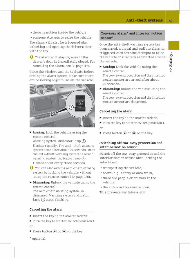
Rthere is motion inside the vehicle
Rsomeone attempts to raise the vehicle
The alarm will also be triggered when
unlocking and opening the driver’s door
with the key.
i The alarm will stay on, even if thedriver’s door is immediately closed. For
canceling the alarm, see (Y page 49).
Close the windows and the tailgate before
arming the alarm system. Make sure there
are no moving objects inside the vehicle.
X Arming: Lock the vehicle using the
remote control.
Warning system indicator lamp:
flashes rapidly. The anti-theft warning
system arms after about 25 seconds. When
the anti-theft warning system is armed,
warning system indicator lamp:
flashes about every three seconds.
i You can also arm the anti-theft warningsystem by locking the vehicle without
using the remote control (Y page 176).
X Disarming: Unlock the vehicle using the
remote control.
The anti-theft warning system is
disarmed. Warning system indicator
lamp: stops flashing.
Canceling the alarm
X Insert the key in the starter switch.
X Turn the key to starter switch position 1.
or
X Press button# or* on the key.
Tow-away alarm* and interior motion
sensor*
Once the anti-theft warning system has
been armed, a visual and audible alarm is
triggered when someone attempts to raise
the vehicle or if motion is detected inside
the vehicle.
X Arming: Lock the vehicle using the
remote control.
The tow-away protection and the interior
motion sensor are armed after about
25 seconds.
X Disarming: Unlock the vehicle using the
remote control.
The tow-away protection and the interior
motion sensor are disarmed.
Canceling the alarm
X Insert the key in the starter switch.
X Turn the key to starter switch position 1.
or
X Press button# or* on the key.
Switching off tow-away protection and
interior motion sensor
Switch off the tow-away protection and the
interior motion sensor when locking the
vehicle and
Rtransporting the vehicle,
Rboard, e.g. a ferry or auto train,
Rthere are people or animals in the
vehicle,
Rthe side windows remain open.
This prevents any false alarm.
Anti-theft systems 49
>>Safety.
* optional Z

X Remove the key from the starter switch.
X Press switch: within 60 seconds.
Indicator lamp; comes on.
X Exit the vehicle.
X Lock the vehicle using the remote
control.
i The tow-away protection and theinterior motion sensor remain switched
off until you lock your vehicle again.
50 Anti-theft systems>>Safety.

>>Controls.
Opening and closing .......................... 52
Starter switch positions ..................... 57
Seats .............................................. 58
Mirrors ........................................... 61
Seat belts ........................................ 62
Lighting ......................................... 64
Windshield wipers ............................ 70
Soft top system (cabriolet only) ............ 71
Side windows .................................... 76
Driving and parking .......................... 77
Transmission ................................... 81
Instrument cluster ............................. 86
Control system* ................................ 92
Audio system* .................................. 98
Driving systems ............................... 100
HVAC (Heating, Ventilation, Air Con-
ditioning) ...................................... 102
Loading and storing ......................... 107
Useful features ................................ 113
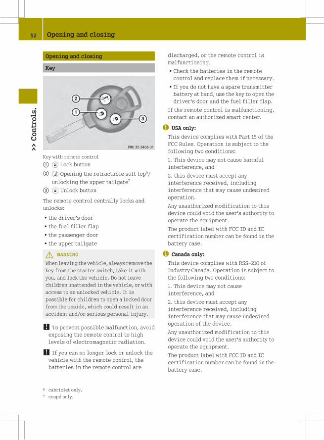
Opening and closing
Key
Key with remote control
: * Lock button
; $ Opening the retractable soft top6/
unlocking the upper tailgate7
= # Unlock button
The remote control centrally locks and
unlocks:
Rthe driver’s door
Rthe fuel filler flap
Rthe passenger door
Rthe upper tailgate
G WARNING
When leaving the vehicle, always remove the
key from the starter switch, take it with
you, and lock the vehicle. Do not leave
children unattended in the vehicle, or with
access to an unlocked vehicle. It is
possible for children to open a locked door
from the inside, which could result in an
accident and/or serious personal injury.
! To prevent possible malfunction, avoidexposing the remote control to high
levels of electromagnetic radiation.
! If you can no longer lock or unlock thevehicle with the remote control, the
batteries in the remote control are
discharged, or the remote control is
malfunctioning.
RCheck the batteries in the remote
control and replace them if necessary.
RIf you do not have a spare transmitter
battery at hand, use the key to open the
driver’s door and the fuel filler flap.
If the remote control is malfunctioning,
contact an authorized smart center.
i USA only:
This device complies with Part 15 of the
FCC Rules. Operation is subject to the
following two conditions:
1. This device may not cause harmful
interference, and
2. this device must accept any
interference received, including
interference that may cause undesired
operation.
Any unauthorized modification to this
device could void the user’s authority to
operate the equipment.
The product label with FCC ID and IC
certification number can be found in the
battery case.
i Canada only:
This device complies with RSS‑210 of
Industry Canada. Operation is subject to
the following two conditions:
1. This device may not cause
interference, and
2. this device must accept any
interference received, including
interference that may cause undesired
operation of the device.
Any unauthorized modification to this
device could void the user’s authority to
operate the equipment.
The product label with FCC ID and IC
certification number can be found in the
battery case.
6 cabriolet only.
7 coupé only.
52 Opening and closing>>Controls.

! The remote control has an operatingrange of approximately 50 ft (15 meters).
This can fluctuate greatly as a
consequence of local conditions
(reflective or absorbing objects) and
interference emitted by other radio
transmission systems. Similarly, the
operating range fluctuates in line with
the direction from which the remote
control is activated.
To prevent theft, however, it is advisable
to only unlock the vehicle when you are
in close proximity to it.
Locking and unlocking from the
outside
X Selective unlocking: Press button# onthe key once.
All turn signal lamps flash once.
The anti-theft warning system* is
disarmed.
The driver’s door and the fuel filler flap
are unlocked.
X Global unlocking: Press button# on thekey twice.
All turn signal lamps flash once again.
The passenger door and the tailgate are
unlocked in addition to the driver’s door
and the fuel filler flap.
X Global locking: Press button* on thekey.
With the doors, the tailgate(s), and the
fuel filler flap closed, the turn signal
lamps flash three times.
The anti-theft warning system* is armed.
The indicator lamp on the central
locking switch flashes (Y page 54).
The interior and exterior8 lamps come on
and then go out again after 12 seconds.
i In vehicles with anti-theft warning
system*, an acoustic signal will sound
when locking or unlocking the vehicle.
When unlocking, the acoustic signal
sounds once. When locking, the acoustic
signal sounds three times.
The acoustic signal is activated at the
factory. If you wish to deactivate the
feature, contact an authorized smart
center.
Automatic locking
Auto-relock function
The vehicle will lock again automatically
within approximately 60 seconds of
unlocking with the key if neither the
driver’s nor passenger door is opened.
! To prevent an inadvertent lockout,never leave your key lying in the vehicle.
Drive lock function
The vehicle locks automatically when the
ignition is switched on and the wheels are
turning at vehicle speeds of approximately
8 mph (14 km/h) or more. The drive lock
function is enabled at the factory.
X Switching on: Switch off the ignition.
X Press the central locking switch
(Y page 54) and button* on the keysimultaneously.
An acoustic signal sounds.
The drive lock function is switched on.
X Switching off: Switch off the ignition.
X Press the central unlocking switch
(Y page 54) and button# on the keysimultaneously.
An acoustic signal sounds.
The drive lock function is switched off.
8 Vehicles with rain-light sensor* only.
Opening and closing 53
>>Controls.
* optional Z

Locking and unlocking from the inside
G WARNING
When leaving the vehicle, always remove the
key from the starter switch, take it with
you, and lock the vehicle. Do not leave
children unattended in the vehicle, or with
access to an unlocked vehicle. A child’s
unsupervised access to a vehicle could
result in an accident and/or serious
personal injury.
You can lock and unlock the vehicle from
inside using the central locking or
unlocking switch. This can be useful, for
example, if you want to unlock the
passenger door from inside or lock the
vehicle before starting to drive.
X Locking: Press central locking
switch:.
The indicator lamp on central locking
switch: comes on, when the starter
switch is in position 1.
The indicator lamp on central locking
switch: flashes, when the starter
switch is in position 0.
With the doors and the tailgate closed,
the vehicle locks.
X Unlocking: Press central unlocking
switch;.
The vehicle unlocks and the indicator
lamp on central locking switch: goes
out.
Opening the doors from the inside
You can open a locked door from the inside.
Open door only when conditions are safe to
do so.
X Pull on inside door handle:.
With the driver’s door open a warning
signal sounds if the exterior lamps are
switched on and the ignition is switched
off.
Opening the upper tailgate on the
coupé
G WARNING
Make sure the tailgate is closed when the
engine is running and while driving.
Among other dangers, deadly carbon
monoxide (CO) gases may enter vehicle
interior resulting in unconsciousness and
death.
54 Opening and closing>>Controls.

X Press button# on the key twice.
X Press and hold button$ on the key forapproximately two seconds.
or
X Pull the release handle in handle
recess: of the lower tailgate.
The upper tailgate is unlocked.
X Swivel the upper tailgate upwards to
open.
Observe the information on loading the
vehicle (Y page 112).
For information on vehicle weights, see
“Vehicle specification” (Y page 215).
Opening the lower tailgate on the
coupé
G WARNING
High outside temperature, stop-and-go
traffic, driving on long uphill grades, or
driving at high engine speed may increase
the temperature in the engine
compartment. Therefore the area around the
air slots in the rear apron may be hot. Let
the engine cool off before touching this
area to prevent burns.
X Open the upper tailgate (Y page 54).
X Pull either of the release levers:
backwards.
The lower tailgate is unlocked.
X Swivel the lower tailgate downwards to
open.
The lower tailgate is held in the
horizontal position by means of the two
retaining straps.
! When folded down, the lower tailgatecan bear loads up to maximum of 220 lbs
(100 kg).
Observe the information on loading the
vehicle (Y page 112).
For information on vehicle weights, see
“Vehicle specification” (Y page 215).
Closing the tailgate(s) on the coupé
G WARNING
To prevent possible personal injury,
always keep hands and fingers away from the
cargo compartment opening when closing
the tailgate(s). Be especially careful when
small children are around.
X Swivel the lower tailgate upwards to
close. Allow the two release levers to
engage audibly.
X Swivel the upper tailgate downwards to
close.
G WARNING
When leaving the vehicle, always remove the
key from the starter switch, take it with
Opening and closing 55
>>Controls.
Z

you, and lock the vehicle. Do not leave
children unattended in the vehicle, or with
access to an unlocked vehicle. A child’s
unsupervised access to a vehicle could
result in an accident and/or serious
personal injury.
Opening and closing the retractable
soft top (cabriolet only)
You can fully open the retractable soft top
with the key.
Key with remote control
: * Lock button
; $ Opening the retractable soft top
= # Unlock button
X Opening: Press button$ on the key forapproximately two seconds.
The retractable soft top opens.
i Pressing symbols#,* or$ on thekey with remote control while opening
the retractable soft top will interrupt
the opening procedure.
X Closing: Press symbolG on the
retractable soft top switch (Y page 56).
G WARNING
When closing the retractable soft top, make
sure there is no danger of anyone being
harmed by the closing procedure.
i The remote control has an operatingrange of approximately 50 ft (15 meters).
Take care that you do not open your
vehicle’s retractable soft top
inadvertently.
Opening the tailgate on the cabriolet
G WARNING
Make sure the tailgate is closed when the
engine is running and while driving.
Among other dangers, deadly carbon
monoxide (CO) gases may enter vehicle
interior resulting in unconsciousness and
death.
G WARNING
High outside temperature, stop-and-go
traffic, driving on long uphill grades, or
driving at high engine speed may increase
the temperature in the engine
compartment. Therefore the area around the
air slots in the rear apron may be hot. Let
the engine cool off before touching this
area to prevent burns.
X Press button# on the key twice.
X Pull the release handle in handle
recess: of the tailgate.
The tailgate is unlocked.
X Swivel the tailgate downwards to open.
Opening and closing the rear soft top
(cabriolet only)
You can open the rear soft top to ease
loading and unloading.
56 Opening and closing>>Controls.
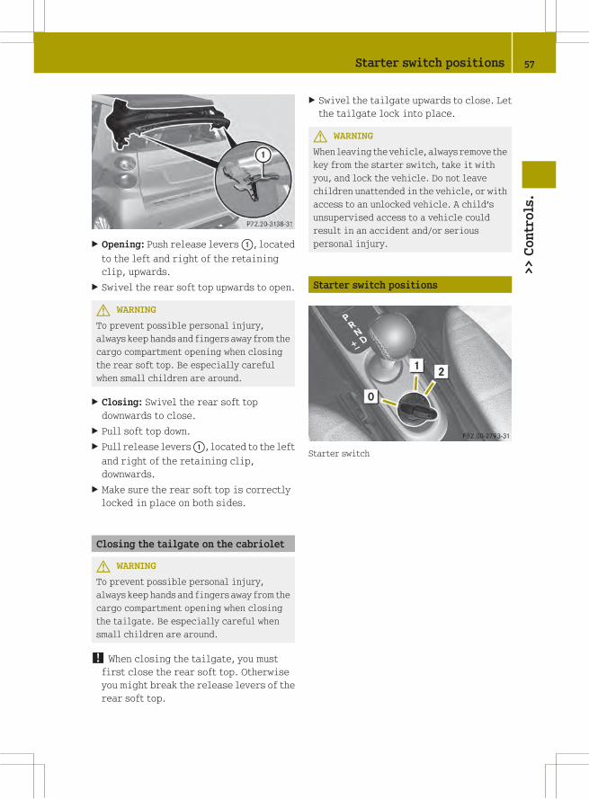
X Opening: Push release levers:, located
to the left and right of the retaining
clip, upwards.
X Swivel the rear soft top upwards to open.
G WARNING
To prevent possible personal injury,
always keep hands and fingers away from the
cargo compartment opening when closing
the rear soft top. Be especially careful
when small children are around.
X Closing: Swivel the rear soft top
downwards to close.
X Pull soft top down.
X Pull release levers:, located to the left
and right of the retaining clip,
downwards.
X Make sure the rear soft top is correctly
locked in place on both sides.
Closing the tailgate on the cabriolet
G WARNING
To prevent possible personal injury,
always keep hands and fingers away from the
cargo compartment opening when closing
the tailgate. Be especially careful when
small children are around.
! When closing the tailgate, you mustfirst close the rear soft top. Otherwise
you might break the release levers of the
rear soft top.
X Swivel the tailgate upwards to close. Let
the tailgate lock into place.
G WARNING
When leaving the vehicle, always remove the
key from the starter switch, take it with
you, and lock the vehicle. Do not leave
children unattended in the vehicle, or with
access to an unlocked vehicle. A child’s
unsupervised access to a vehicle could
result in an accident and/or serious
personal injury.
Starter switch positions
Starter switch
Starter switch positions 57
>>Controls.
Z

g For removing key
1 Ignition (power supply for all
electrical consumers) and driving
position
All lamps (except low‑beam
headlamp indicator lamp,
high‑beam headlamp indicator
lamp, and turn signal indicator
lamps unless activated) in the
instrument cluster come on. If a
lamp in the instrument cluster fails
to come on when the ignition is
switched on, have it checked and
replaced if necessary. If a lamp in
the instrument cluster remains on
after starting the engine or comes
on while driving, refer to “Warning
and indicator lamps in the
instrument cluster” (Y page 162).
2 Starting (Y page 77)
i When you switch on the ignition, theindicator and warning lamps (except
low‑beam headlamp indicator lamp,
high‑beamheadlamp indicator lamp, and
turn signal indicator lamps unless
activated) in the instrument cluster
come on. The indicator and warning
lamps (except low‑beam headlamp
indicator lamp, high‑beam headlamp
indicator lamp, and turn signal
indicator lamps if activated) will go out
when the engine is running. This
indicates that the respective systems
are operational.
Seats
Safety notes
G WARNING
All seat adjustments, as well as fastening
of seat belts, must be done before the
vehicle is operated.
G WARNING
When adjusting the seat, make sure no one
becomes trapped.
Do not adjust the driver’s seat while
driving. Adjusting the seat while driving
could cause the driver to lose control of the
vehicle.
Never ride in amoving vehicle with the seat
backrest in an excessively reclined
position as this can be dangerous. You
could slide under the seat belt in a
collision. If you slide under the seat belt,
it could apply force at the abdomen or neck,
potentially causing serious or fatal
injuries. The seat backrest and seat belts
provide the best restraint when the wearer
is in a position that is as upright as
possible and seat belts are properly
positioned on the body.
Your seat must be adjusted so that you can
correctly fasten your seat belt.
Observe the following points:
RAdjust the seat backrest until your arms
are slightly angled when holding the
steering wheel.
RAdjust the seat to a comfortable seating
position that still allows you to reach the
accelerator/brake pedal safely. The
position should be as far back as
possible with the driver still able to
operate the controls properly.
RNever place hands under the seat or near
any moving parts while a seat is being
adjusted.
Failure to do so could result in an accident
and/or serious personal injury.
Observe the notes on the air bag system.
G WARNING
Children 12 years old and under must be
seated and properly secured in an
appropriately sized infant restraint,
toddler restraint, or booster seat
recommended for the size and weight of the
58 Seats>>Controls.

child. For additional information, see
“Children in the vehicle”.
A child’s risk of serious or fatal injuries
is significantly increased if the child
restraints are not properly secured in the
vehicle and/or the child is not properly
secured in the child restraint.
G WARNING
Contact an authorized smart center if the
seats have become damaged.
The seat is an integral part of the vehicle’s
safety system in the same way as seat belts
and air bags. Damage to the seats may
reduce their ability to protect the
occupants in an accident.
Seat adjustment
: Seat backrest tilt
; Seat fore and aft adjustment
Seat backrest tilt
X Pull adjustment lever: upwards and
adjust the seat backrest until your arms
are slightly angled when holding the
steering wheel.
X Release adjustment lever: when the
desired seat backrest tilt is reached.
When you hear an audible click, the seat
backrest is again fixed into place.
X Check for proper engagement before
driving.
Seat fore and aft adjustment
X Pull adjustment handle; upwards and
slide the seat to a seating position that
still allows you to reach the accelerator/
brake pedal safely.
X Release adjustment handle; when the
desired seating position is reached.
When you hear an audible click, the seat
is again fixed into place.
X Check for proper engagement before
driving.
Seat height
The seat guide is inclined in the
horizontal plane. Seat fore and aft
adjustment also alters the seat height.
Armrest* on driver’s seat
Folding up and down
X Folding up:Hold front of armrest and fold
it up in direction of arrow:.
X Folding down: Hold front of armrest and
fold it down in direction of arrow;.
Adjusting armrest angle
You can adjust the angle of the armrest when
it is folded down.
X Turn thumb wheel=.
RDirection of arrow?: down
RDirection of arrowA: up
Seats 59
>>Controls.
* optional Z

Passenger seat
You can expand the cargo compartment by
folding down the passenger seat.
Observe the loading instructions
(Y page 112).
Folding down
X Remove the seat belt from seat belt
guide:.
X Move the passenger seat backward as far
as it will go.
X Hold the backrest with one hand back.
X Pull adjustment lever; upwards and
unlock the seat backrest.
X Fold the seat backrest forward.
Folding back
X Pull adjustment lever; upwards and
unlock the seat backrest.
X Fold the seat backrest backward.
When you hear an audible click, the seat
backrest is again fixed into place.
X Check for proper engagement before
driving.
X Place the seat belt back in seat belt
guide:.
G WARNING
When folding the passenger seat backrest
back to its upright position, please make
sure
Rnobody becomes trapped
Rno obstacles are jammed in the lock
Rthe adjustment lever has audibly locked
into position
A properly engaged passenger seat
backrest will help to prevent stored
objects in the cargo compartment from
being thrown about and injuring vehicle
occupants during
Rbraking
Rvehicle maneuvers
Ran accident
Seat heating*
The seat heating allows you to heat the
driver’s and passenger seat electrically.
The seat heating has two levels.
The indicator lamps on seat heating
switch: come on to show which heating
level you have selected.
60 Seats>>Controls.
* optional

Level Indicator lamps on the switch
off No indicator lamp on
1 One indicator lamp on
2 Two indicator lamps on
X Make sure the key is in starter switch
position 1.
X Switching on: Press seat heating
switch: repeatedly until the desired
seat heating level is reached.
X Switching off: Press seat heating
switch: repeatedly until all indicator
lamps go out.
! If the seat heating is malfunctioning,the indicator lamp(s) on the switch
come(s) on briefly when you press the
switch and then go(es) out again. Contact
an authorized smart center.
Mirrors
Adjust the interior and exterior rear view
mirrors before driving so that you have a
good view of the road and traffic
conditions.
Exterior rear view mirrors
G WARNING
Exercise care when using the passenger-
side exterior rear view mirror. The mirror
surface is convex (outwardly curved surface
for a wider field of view). Objects inmirror
are closer than they appear. Check your
interior rear view mirror and glance over
your shoulder to determine whether any
vehicles are in the ’blind spot’ of your field
of vision, before changing lanes.
Manually adjustable exterior rear view
mirrors
X Adjusting: Move adjustment lever: up,
down, left, or right to the desired
setting.
Power exterior rear view mirrors
This feature is only available on the model
passion and BRABUS.
The operating control is on the door
control panel.
X Make sure the key is in starter switch
position 1.
X Selecting the mirror: Turn knob: to the
left for the driver’s side exterior rear
view mirror or to the right for the
passenger side exterior rear view
mirror.
X Adjusting the mirror: Move adjustment
button; up, down, left, or right to the
desired setting.
Mirrors 61
>>Controls.
Z

Exterior rear view mirror heating
This feature is only available on the model
passion and BRABUS and in conjunction
with power exterior rear view mirrors.
After switching on the rear window
defroster, the exterior rear view mirrors
will be heated automatically. This
prevents icing up the exterior rear view
mirrors and also creates a clear view when
the exterior rear view mirrors have fogged
up.
If the rear window defroster is
automatically deactivated after
approximately 10 minutes of operation, the
exterior rear view mirror heating also
deactivates.
X Make sure the key is in starter switch
position 1.
X Switching on: Switch on the rear window
defroster (Y page 106).
The exterior rear view mirror heating is
switched on.
X Switching off: Switch off the rear window
defroster (Y page 106).
The exterior rear view mirror heating is
switched off.
i The exterior rear view mirror heatingalso switches off if the key is turned to
starter switch position 0.
Interior rear view mirror
X Adjusting the mirror: Manually move the
interior rear view mirror up, down, left,
or right to the desired setting.
X Selecting the antiglare position: Tilt
the interior rear view mirror to the
antiglare position by moving lever:
forward or backward.
Seat belts
Fastening the seat belts
G WARNING
Always fasten your seat belt before driving.
Always make sure all of your passengers are
properly restrained.
Failure to wear and properly fasten and
position your seat belt greatly increases
your risk of injuries and their likely
severity in an accident. You and your
passenger should always wear seat belts.
If you are ever in an accident, your injuries
can be considerably more severe without
your seat belt properly buckled.
Without your seat belt buckled, you are
much more likely to hit the interior of the
vehicle or be ejected from it. You can be
seriously injured or killed.
In the same crash, the possibility of injury
or death is lessened if you are properly
wearing your seat belt. Air bags can only
protect you if you are properly wearing
your seat belt.
G WARNING
Children 12 years old and under must be
seated and properly secured in an
appropriately sized infant restraint,
toddler restraint, or booster seat
recommended for the size and weight of the
child. For additional information, see
“Children in the vehicle”.
A child’s risk of serious or fatal injuries
is significantly increased if the child
restraints are not properly secured in the
62 Seat belts>>Controls.

vehicle and/or the child is not properly
secured in the child restraint.
G WARNING
Never let more people ride in the vehicle
than there are seat belts available. Make
sure everyone riding in the vehicle is
correctly restrained with a separate seat
belt. Never use a seat belt for more than one
person at a time.
G WARNING
Never ride in amoving vehicle with the seat
backrest in an excessively reclined
position as this can be dangerous. You
could slide under the seat belt in a
collision. If you slide under it, the belt
would apply force at the abdomen or neck,
causing serious or even fatal injuries. The
seat backrest and seat belt provide the best
restraint when the wearer is in a position
that is as upright as possible and the belt
is properly positioned on the body.
G WARNING
Observe ”Safety notes“ (Y page 35).
: Seat belt outlet
; Seat belt guide
= Latch plate
? Seat belt buckle
A Release button
X Fastening the seat belt: With a smooth
motion, pull the seat belt out of seat belt
outlet:.
X Place the shoulder portion of the seat
belt across the top of your shoulder and
the lap portion across your hips.
X Push latch plate= into seat belt
buckle? until it clicks.
X If necessary, tighten the lap portion of
the seat belt to a snug fit by pulling
shoulder portion up.
X Unfastening the seat belt: Press release
buttonA.
X Allow the retractor to completely rewind
the seat belt by guiding latch plate=.
Proper use of seat belts
RDo not twist the seat belt when fastening.
RAdjust the seat belt so that the shoulder
portion is located as close as possible
to the middle of the shoulder (it should
Seat belts 63
>>Controls.
Z

not touch the neck). Never pass the
shoulder portion of the seat belt under
your arm.
RPosition the lap belt as low as possible
on your hips (over hip joint) and not
across the abdomen.
RPlace the seat backrest in a position that
is as upright as possible.
RNever use a seat belt for more than one
person at a time.
RDo not fasten a seat belt around a person
and another object at the same time. When
using a seat belt to secure infant or
toddler restraints or children in booster
seats, always follow the child seat
manufacturer’s instructions.
RCheck your seat belt during travel to
make sure it is properly positioned.
RMake sure the seat belt is always fitted
snugly. Take special care to maintain a
snug fit when wearing loose clothing.
G WARNING
Do not pass seat belts over sharp edges.
They could tear.
Do not allow the seat belt to get caught in
the door or in the seat adjustment
mechanism. This could damage the seat
belt.
Never attempt to make modifications to
seat belts. This could impair the
effectiveness of the seat belts.
Do not bleach or dye seat belts as this may
severely weaken them. In a crash they may
not be able to provide adequate protection.
Damaged seat belts or seat belts that were
highly stressed in an accident must be
replaced. Contact an authorized smart
center.
Correct driver seat adjustment
G WARNING
Observe ”Safety notes“ (Y page 58).
X Adjust the driver’s seat properly
(Y page 59).
Make sure that you
Rare positioned as far away from the
driver’s front air bag as possible
Rcan reach steering wheel: with your
arms slightly bent at the elbows
Rcan fasten seat belt; properly
Ryou have adjusted seat backrest= to
a position that is as upright as
possible
Ryou can move your legs freely
Ryou can depress the brake and
accelerator pedal safely.
X Make sure the seat belt is fastened
properly (Y page 62).
Lighting
Exterior lamp switch
For safety, smart recommends that you
drive with your low‑beam headlamps on
during the day. In certain countries, local
laws dictate that low‑beam headlamps are
switched on automatically during
operation of the vehicle.
64 Lighting>>Controls.

i If you drive in countries wherevehicles drive on the other side of the
road than the country in which the
vehicle is registered, you must have the
headlamps modified for symmetrical low
beams. Relevant information can be
obtained at any authorized smart center.
Exterior lamp switch
$ Lamps off
Daytime running lamp mode*
T Parking lamps
L Low‑beam headlamps or high‑beam
headlamps
à Automatic headlamp mode*
Parking lamps
You can switch on and off the parking lamps
with the exterior lamp switch using the
manual headlamp mode.
X Switching on: Turn the exterior lamp
switch to positionT.
The parking lamps come on.
The following lamps also come on:
RTail lamps
RLicense plate lamps
RSide marker lamps
Low‑beam headlamps
You can switch on and off the low‑beam
headlamps with the exterior lamp switch
using the manual headlamp mode.
X Switching on: Turn the exterior lamp
switch to positionL.
The low‑beam headlamps come on.
The low‑beam headlamp indicator lamp
M in the instrument cluster comes on.
The following lamps also come on:
RTail and parking lamps
RLicense plate lamps
RSide marker lamps
Automatic headlamp mode*
This feature is only available on vehicles
with rain-light sensor*.
The following lamps come on and go out
automatically depending on the brightness
of the ambient light:
RLow‑beam headlamps
RTail and parking lamps
RLicense plate lamps
RSide marker lamps
G WARNING
If the exterior lamp switch is set to
positionÃ, the headlamps will not be
automatically switched on under foggy
conditions.
To minimize risk to you and to others,
activate headlamps by turning exterior
lamp switch to positionL when driving
or when traffic and/or ambient lighting
conditions require you to do so.
In low ambient lighting conditions, only
switch from positionà toL with the
vehicle at a standstill in a safe location.
Switching from positionà toL will
briefly switch off the headlamps. Doing so
while driving in low ambient lighting
conditions may result in an accident.
The automatic headlamp feature is only an
aid to the driver. The driver is responsible
for the operation of the vehicle’s lights at
all times.
Lighting 65
>>Controls.
* optional Z

X Turn the exterior lamp switch to position
Ã.
With the key in starter switch position
1, the tail and parking lamps, the license
plate lamps, and the side marker lamps
will come on and go out automatically
depending on the brightness of the
ambient light.
With the engine running, the low‑beam
headlamps, the tail and parking lamps,
the license plate lamps and the side
marker lamps will come on and go out
automatically depending on the
brightness of the ambient light.
Daytime running lamp mode*
In USA, the daytime running lamp mode can
be deactivated.
In Canada, the daytime running lamp mode
is mandatory and therefore in a constant
mode.
Depending on the vehicle equipment, your
vehicle comes either with low-beam
daytime running lamps or with LED daytime
running lamps.
Switching on:
X Start the engine.
The daytime running lamps are switched
on.
On vehicles with low beam daytime
running lamps the parking lamps also
come on.
Switching off - vehicles without rain-
light sensor*:
X Switch on the parking lampsT or the
low‑beam headlampsM.
The daytime running lamps are switched
off.
Switching off - vehicles with rain-light
sensor*:
X Switch on the parking lampsT or the
low‑beam headlampsM.
The daytime running lamps are switched
off.
or
X Turn the exterior lamp switch to position
Ã.
With the engine running, the low‑beam
headlamps, the tail and parking lamps,
the license plate lamps and the side
marker lamps will come on and go out
automatically depending on the
brightness of the ambient light.
Deactivating (USA only):
X Switch off the ignition.
X Remove the key from the starter switch.
X Switch on the high-beam flasher and
press button# on the keysimultaneously.
An acoustic signal sounds.
The daytime running lamp mode is
deactivated.
Reactivating (USA only):
X Switch off the ignition.
X Remove the key from the starter switch.
X Switch on the high-beam flasher and
press button# on the keysimultaneously.
An acoustic signal sounds.
The daytime running lamp mode is
reactivated.
Combination switch (high beam, high
beam flasher and turn signals)
X Make sure the key is in starter switch
position 1.
66 Lighting>>Controls.
* optional
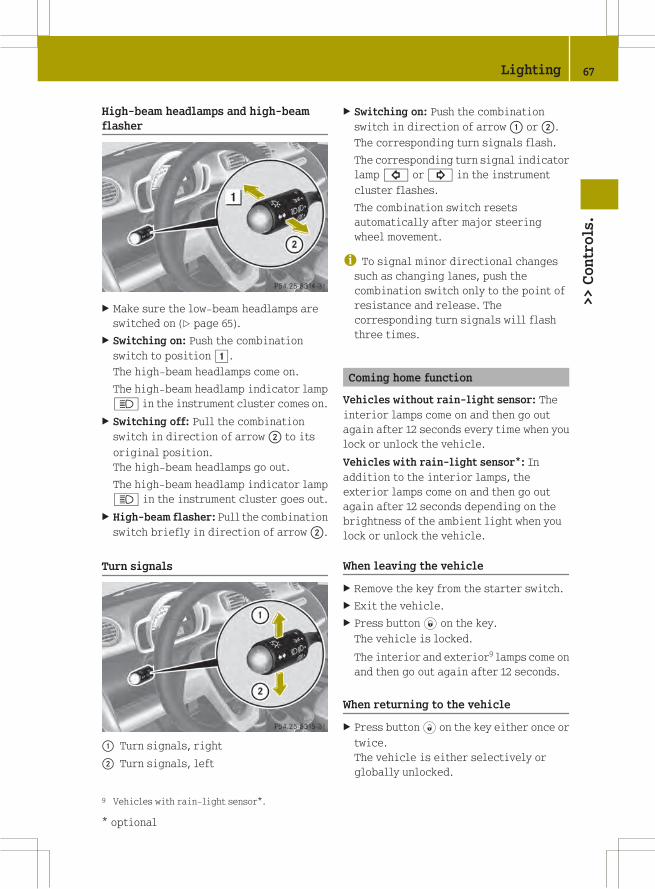
High‑beam headlamps and high-beam
flasher
X Make sure the low‑beam headlamps are
switched on (Y page 65).
X Switching on: Push the combination
switch to position1.
The high‑beam headlamps come on.
The high‑beam headlamp indicator lamp
K in the instrument cluster comes on.
X Switching off: Pull the combination
switch in direction of arrow; to its
original position.
The high‑beam headlamps go out.
The high‑beam headlamp indicator lamp
K in the instrument cluster goes out.
X High-beam flasher: Pull the combination
switch briefly in direction of arrow;.
Turn signals
: Turn signals, right
; Turn signals, left
X Switching on: Push the combination
switch in direction of arrow: or;.
The corresponding turn signals flash.
The corresponding turn signal indicator
lamp# or! in the instrument
cluster flashes.
The combination switch resets
automatically after major steering
wheel movement.
i To signal minor directional changessuch as changing lanes, push the
combination switch only to the point of
resistance and release. The
corresponding turn signals will flash
three times.
Coming home function
Vehicles without rain-light sensor: The
interior lamps come on and then go out
again after 12 seconds every time when you
lock or unlock the vehicle.
Vehicles with rain-light sensor*: In
addition to the interior lamps, the
exterior lamps come on and then go out
again after 12 seconds depending on the
brightness of the ambient light when you
lock or unlock the vehicle.
When leaving the vehicle
X Remove the key from the starter switch.
X Exit the vehicle.
X Press button* on the key.The vehicle is locked.
The interior and exterior9 lamps come on
and then go out again after 12 seconds.
When returning to the vehicle
X Press button# on the key either once ortwice.
The vehicle is either selectively or
globally unlocked.
9 Vehicles with rain-light sensor*.
Lighting 67
>>Controls.
* optional Z

The interior and exterior9 lamps come on
and then go out again after 12 seconds.
Ambient lighting*
The ambient lighting illuminates the
vehicle interior with 6 LEDs when the low-
beam headlamps are switched on. The LEDs
can be dimmed.
The LEDS are located
Rin the overhead control panel
Rin the door pockets, driver’s and
passenger side
Rin the storage trays to the left and right
of the steering wheel
In addition to the ambient lighting, the
footwells on the driver’s and passenger
side are also illuminated by separate
lamps.
i When you open a door, the interiorlighting comes on and the brightness of
lamps in the footwells increases.
X Make sure the key is in starter switch
position 1.
X Switch on the parking lamps.
X To brighten or dim ambient lighting:
Press button: on the instrument cluster
repeatedly until the desired setting is
reached.
The current setting is stored.
i When adjusting the ambient lighting,the illumination level for instrument
cluster is also changed (Y page 92).
Front fog lamps
G WARNING
Vehicles with rain-light sensor*:
In low ambient lighting or foggy
conditions, only switch from position
à toL with the vehicle at a
standstill in a safe location. Switching
fromà toL will briefly switch off
the headlamps. Doing so while driving in
low ambient lighting conditions may result
in an accident.
i Fog lamps will operate with the parkinglamps and/or the low‑beam headlamps on.
Fog lamps should only be used in
conjunction with low‑beam headlamps.
Consult your State or Province Motor
Vehicle Regulations regarding
permissible lamp operation.
i Vehicle with rain-light sensor*:
Fog lamps cannot be switched onmanually
with the exterior lamp switch in
positionÃ. To switch on the fog
lamps, turn the exterior lamp switch to
positionL first.
9 Vehicles with rain-light sensor*.
68 Lighting>>Controls.
* optional

X Make sure the parking lamps or the
low‑beam headlamps are switched on.
X Switching on: Press switch:.
The front fog lamps come on.
The indicator lamp in the switch comes
on.
X Switching off: Press switch: once
more.
The front fog lamps go out.
The indicator lamp in the switch goes
out.
Hazard warning flasher
The hazard warning flasher can be switched
on at all times, even with the key removed
from the starter switch.
X Switching on: Press hazard warning
flasher switch:.
All turn signal lamps are flashing.
X Switching off: Press hazard warning
flasher switch: once more.
Interior lighting
The interior lamp comes on for a period of
time when you open the doors, or lock or
unlock the vehicle with the key.
It goes out
Rimmediately after switching off the
ignition with all doors closed
Rafter 30 seconds if the doors are not
opened
Rafter 15 seconds if all doors are closed
Rafter 10 minutes if at least one door is
open
The rocker switch can be set to three
different positions.
: Interior lamp
; Off
= Switching on the automatic control
? Continuous operation
Automatic control
X Set the rocker switch to position=.
The interior lamp comes on for a period
of time.
Switching off
X Set the rocker switch to position;.
The interior lamp is permanently
switched off.
Continuous operation
X Set the rocker switch to position?.
The interior lamp is permanently
switched on.
! When leaving the vehicle, make sure theinterior lamp is not set to continuous
operation and none of the doors is left
open for a long period of time.
Doing otherwise could result in a
discharged battery.
Lighting 69
>>Controls.
Z

Windshield wipers
Switching windshield wipers on and off
Example illustration coupé
X Make sure the key is in starter switch
position 1.
X Switching on: Turn the wiper switch to
position2 or3, depending on the
intensity of the rain.
! Do not operate the windshield wiperswhen the windshield is dry. Dust that
accumulates on a windshield might
scratch the glass and/or damage the
wiper blades when wiping occurs on a dry
windshield. If it is necessary to operate
the windshield wipers in dry weather
conditions, always operate the
windshield wipers with windshield
washer fluid.
! If anything blocks the windshieldwipers (leaves, snow, etc.), switch them
off immediately.
For safety reasons, stop the vehicle in a
safe location and
R- remove the key from the starter
switch
- engage the parking brake
before attempting to remove any
blockage.
RRemove blockage.
RTurn the windshield wipers on again.
X Switching off: Turn the wiper switch to
positiong.
Intermittent wiping
Only switch on intermittent wiping under
wet weather conditions or in the presence
of precipitation.
Vehicles with rain-light sensor*: When you
select intermittent wiping, the sensor is
activated. The sensor automatically sets a
suitable wiping interval depending on the
wetness of the sensor surface.
! Vehicles with rain-light sensor*:
Do not leave windshield wipers in
intermittent setting when the vehicle is
taken to an automatic car wash or during
windshield cleaning. Windshield wipers
will operate in the presence of water
sprayed on the windshield, and
windshield wipers may be damaged as a
result.
! Vehicles with rain-light sensor*:
If you have set intermittent wiping, dirt
on the surface of the sensor or optical
effects may cause the windshield wipers
to wipe in an undesired fashion. This
could then damage the windshield wiper
blades or scratch the windshield. You
should therefore switch off the
windshield wipers when weather
conditions are dry.
X Make sure the key is in starter switch
position 1.
X Activating intermittent wiping: Turn the
wiper switch to position1.
After the initial wipe, pauses between
wipes are automatically controlled
depending on the vehicle speed and by the
rain-light sensor*.
X Deactivating intermittent wiping: Turn
the wiper switch to positiong.
70 Windshield wipers>>Controls.
* optional

Wiping with windshield washer fluid
Example illustration coupé
X Pull the wiper switch in direction of
arrow: and hold it in position.
The windshield wipers operate with
windshield washer fluid.
X Release the wiper switch.
The windshield wipers will wipe three
more times.
i To prevent smears on the windshield, ornoisy/chattering wiper blades, wipe
with windshield washer fluid
periodically even when it is raining.
Single wipe
X Pull the wiper switch briefly in
direction of arrow:.
The windshield wipers wipe one time
with windshield washer fluid.
Rear window wiper/washer (coupé only)
X Make sure the key is in starter switch
position 1.
X Activating intermittent wiping: Push the
wiper switch to position1.
X Wiping with windshield washer fluid:
Push the wiper switch in direction of
arrow; and hold in position until the
rear window is clean.
X Release the wiper switch.
The rear window wiper will wipe three
more times.
Intermittent wiping is still activated.
X Deactivating intermittent wiping: Pull
the wiper switch back to start position.
i The rear window wiper wipes one timewhen reverse gear R is engaged with the
windshield wipers switched on.
Soft top system (cabriolet only)
Introduction
The soft top system of the smart cabriolet
consists of a
Rretractable soft top
Rrear soft top
Rside rails
You can remove the side rails over the doors
when you open the retractable soft top and
open the rear soft top.
i Opening the rear soft top is possibleafter the retractable soft top has been
opened completely.
Notes on the soft top system
! When transporting long objects insidethe vehicle, make sure they do not press
against the retractable soft top when it
is closed.
When carrying objects that protrude from
the rear of the vehicle, make sure they
are not resting on the retaining clips.
Soft top system (cabriolet only) 71
>>Controls.
Z

When loading, make sure no sharp objects
come into contact with the soft top or the
rear window.
Do not place any evenly distributed loads
with a weight of more than 165 lbs (75 kg)
on the rear soft top when folded down.
Make sure the high-mounted brake lamp
is not concealed.
! Do not block the soft top system’slocking apertures.
Only place the side rails in the
designated storage space of the tailgate.
! Do not sit on the folded-down rear softtop.
Do not fold down the rear soft top at
temperatures below 14¦ (-10¥).
Do not place any pointed, sharp-edged,
hot (above 176¦ [80¥]), incandescent or
burning objects on the soft top’s lining.
Do not apply wax to the soft top fabric and
select only wax-free washing products
when using an automatic car wash.
Only drive with the retaining clips
closed, as exhaust fumes could otherwise
reach the vehicle’s interior.
! Please keep in mind that weatherconditions can sometimes change
rapidly. Make sure to close the
retractable soft top and the rear soft top
when leaving the vehicle. If water enters
the vehicle interior, vehicle
electronics could be damaged which is
not covered by the smart Limited
Warranty.
Opening and closing the retractable
soft top
You can open and close the retractable soft
top when the vehicle is either stationary
or in motion.
G WARNING
Never operate the retractable soft top if
there is the possibility of anyone being
harmed by the opening or closing
procedure.
G WARNING
The retractable soft top is made out of
fabric. In the event of an accident, the
fabric may tear. This may result in an
opening in the roof.
In a vehicle rollover, occupants not
wearing their seat belts or not wearing
them properly may be thrown out of the
opening. Such an opening also presents a
potential for injury for occupants wearing
their seat belts properly as entire body
parts or portions of themmay protrude from
the passenger compartment.
G WARNING
When leaving the vehicle, always remove the
key from the starter switch, take it with
you, and lock the vehicle. Do not leave
children unattended in the vehicle, or with
access to an unlocked vehicle. A child’s
unsupervised access to a vehicle could
result in an accident and/or serious
personal injury.
! To avoid damaging the seals, do nottransport any objects with sharp edges
which can stick out of the retractable
soft top.
Do not open the retractable soft top if
there is snow or ice on the roof, as this
could result in malfunctions.
If you cannot open or close the
retractable soft top due to a malfunction
contact Roadside Assistance or an
authorized smart center.
i To avoid draining the battery, leave theengine running when opening and
closing the retractable soft top.
72 Soft top system (cabriolet only)>>Controls.

Opening from outside
You can open the retractable soft top
completely with the key.
Key with remote control
: * Lock button
; $ Opening the retractable soft top
= # Unlock button
X Press button$ on the key forapproximately two seconds.
The retractable soft top opens
completely.
Opening from the inside
X Make sure the key is in starter switch
position 1.
X Press symbol; on the retractable soft
top switch until the desired position is
reached or the retractable soft top is
opened completely.
or
X Press symbol; on the retractable soft
top switch briefly.
The retractable soft top opens
completely.
i Pressing symbol: or; on the
retractable soft top switch while
opening the retractable soft top will
interrupt the opening procedure.
Closing
For safety reasons, you can only close the
retractable soft top using the retractable
soft top switch inside the vehicle.
X Make sure the key is in starter switch
position 1.
X Press symbol: on the retractable soft
top switch until the retractable soft top
is closed.
Opening and closing the rear soft top
You can open and close the rear soft top
when the vehicle is either stationary or in
motion.
G WARNING
Never operate the rear soft top if there is
the possibility of anyone being harmed by
the opening or closing procedure.
! Make sure objects are not stacked toohigh in the cargo compartment. They
could get damaged when opening or
closing the rear soft top.
! When the rear soft top is folded down,the side rails are accessible. To prevent
theft, you should remove the side rails
and store them in the storage
compartment of the tailgate or close the
soft top system.
Soft top system (cabriolet only) 73
>>Controls.
Z

X Make sure the key is in starter switch
position 1.
Retractable soft top switch
: Closing
; Opening
Opening the rear soft top
X Press symbol; on the retractable soft
top switch or button$ on the key untilthe retractable soft top has opened
completely.
X Release retractable soft top switch; or
button$ on the key.
X Press symbol; on the retractable soft
top switch once more until the rear soft
top has folded down completely.
Closing the rear soft top
X Press symbol: on the retractable soft
top switch until the rear soft top has
folded up completely.
X Release retractable soft top switch:.
i If you release the retractable soft topswitch while driving before the rear soft
top has closed completely, the rear soft
top will fold down again.
Removing the side rails
X Open the retractable soft top
(Y page 56).
X Open the rear soft top (Y page 73).
X Open the driver’s and passenger door
when conditions are safe to do so.
X Open the tailgate (Y page 56).
X Pull handle: on the inside of the
tailgate backward.
X Lift up the storage compartment cover.
X Push release lever= of side rail;
backward.
Side rail; can be lifted at the rear end,
but remains secured.
X Push release lever= backward again.
74 Soft top system (cabriolet only)>>Controls.
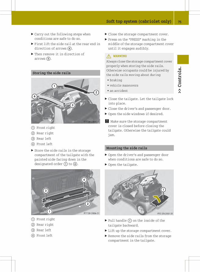
X Carry out the following steps when
conditions are safe to do so.
X First lift the side rail at the rear end in
direction of arrows?.
X Then remove it in direction of
arrowsA.
Storing the side rails
: Front right
; Rear right
= Rear left
? Front left
X Store the side rails in the storage
compartment of the tailgate with the
painted side facing down in the
designated order: to?.
: Front right
; Rear right
= Rear left
? Front left
X Close the storage compartment cover.
X Press on the “PRESS” marking in the
middle of the storage compartment cover
until it engages audibly.
G WARNING
Always close the storage compartment cover
properly when storing the side rails.
Otherwise occupants could be injured by
the side rails moving about during
Rbraking
Rvehicle maneuvers
Ran accident
X Close the tailgate. Let the tailgate lock
into place.
X Close the driver’s and passenger door.
X Open the side windows if desired.
! Make sure the storage compartmentcover is closed before closing the
tailgate. Otherwise the tailgate could
jam.
Mounting the side rails
X Open the driver’s and passenger door
when conditions are safe to do so.
X Open the tailgate.
X Pull handle: on the inside of the
tailgate backward.
X Lift up the storage compartment cover.
X Remove the side rails from the storage
compartment in the tailgate.
Soft top system (cabriolet only) 75
>>Controls.
Z

; Front right
= Rear right
? Rear left
A Front left
X Install the side rails with the respective
front end; orA first.
G WARNING
Make sure the side rails are properly
mounted. Otherwise the side rails could
disengage while driving and injure you and
other persons.
X Take one side rail and start by attaching
it to front endD.
X Make sure the seal of the side rail is
facing up at positionB and is not
pinched.
X Push the side rail at rear endC
downwards until it audibly engages into
place twice.
X Install the side rail on the other side in
the same manner.
! Make sure the side rails are installedcorrectly. Otherwise the side rails may
not function properly or may be damaged.
X Close the storage compartment cover.
X Press on the “PRESS” marking in the
middle of the storage compartment cover
until it engages audibly.
X Close the tailgate. Let the tailgate lock
into place.
X Close the driver’s and passenger door.
X Open the side windows if desired.
! Make sure the storage compartmentcover is closed before closing the
tailgate. Otherwise the tailgate could
jam.
Side windows
Opening and closing the side windows
Opening and closing the side windows
manually
Crank for side window on passenger door
Side window on the driver’s door
X Opening: Turn crank:
counterclockwise.
X Closing: Turn crank: clockwise.
Side window on the passenger door
X Opening: Turn crank: clockwise.
X Closing: Turn crank:
counterclockwise.
76 Side windows>>Controls.
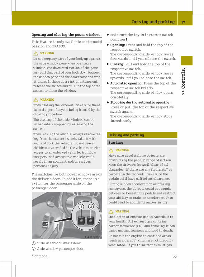
Opening and closing the power windows
This feature is only available on the model
passion and BRABUS.
G WARNING
Do not keep any part of your body up against
the side window pane when opening a
window. The downward motion of the pane
may pull that part of your body downbetween
the window pane and the door frame and trap
it there. If there is a risk of entrapment,
release the switch and pull up the top of the
switch to close the window.
G WARNING
When closing the windows, make sure there
is no danger of anyone being harmed by the
closing procedure.
The closing of the side windows can be
immediately stopped by releasing the
switch.
When leaving the vehicle, always remove the
key from the starter switch, take it with
you, and lock the vehicle. Do not leave
children unattended in the vehicle, or with
access to an unlocked vehicle. A child’s
unsupervised access to a vehicle could
result in an accident and/or serious
personal injury.
The switches for both power windows are on
the driver’s door. In addition, there is a
switch for the passenger side on the
passenger door.
: Side window driver’s door
; Side window passenger door
X Make sure the key is in starter switch
position 1.
X Opening: Press and hold the top of the
respective switch.
The corresponding side window moves
downwards until you release the switch.
X Closing: Pull and hold the top of the
respective switch.
The corresponding side window moves
upwards until you release the switch.
X Automatic opening: Press the top of the
respective switch briefly.
The corresponding side window opens
completely.
X Stopping during automatic opening:
Press or pull the top of the respective
switch again.
The corresponding side window stops
immediately.
Driving and parking
Starting
G WARNING
Make sure absolutely no objects are
obstructing the pedals’ range of motion.
Keep the driver’s footwell clear of all
obstacles. If there are any floormats* or
carpets in the footwell, make sure the
pedals still have sufficient clearance.
During sudden acceleration or braking
maneuvers, the objects could get caught
between or beneath the pedals and restrict
your ability to brake or accelerate. This
could lead to accidents and/or injury.
G WARNING
Inhalation of exhaust gas is hazardous to
your health. All exhaust gas contains
carbon monoxide (CO), and inhaling it can
cause unconsciousness and lead to death.
Do not run the engine in confined areas
(such as a garage) which are not properly
ventilated. If you think that exhaust gas
Driving and parking 77
>>Controls.
* optional Z
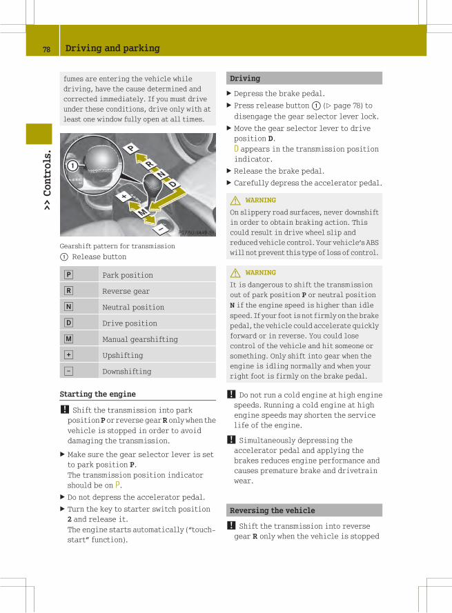
fumes are entering the vehicle while
driving, have the cause determined and
corrected immediately. If you must drive
under these conditions, drive only with at
least one window fully open at all times.
Gearshift pattern for transmission
: Release button
j Park position
k Reverse gear
i Neutral position
h Drive position
p Manual gearshifting
q Upshifting
± Downshifting
Starting the engine
! Shift the transmission into parkposition P or reverse gearR only when the
vehicle is stopped in order to avoid
damaging the transmission.
X Make sure the gear selector lever is set
to park position P.
The transmission position indicator
should be on P.
X Do not depress the accelerator pedal.
X Turn the key to starter switch position
2 and release it.
The engine starts automatically (“touch-
start” function).
Driving
X Depress the brake pedal.
X Press release button: (Y page 78) to
disengage the gear selector lever lock.
X Move the gear selector lever to drive
position D.
D appears in the transmission position
indicator.
X Release the brake pedal.
X Carefully depress the accelerator pedal.
G WARNING
On slippery road surfaces, never downshift
in order to obtain braking action. This
could result in drive wheel slip and
reduced vehicle control. Your vehicle’s ABS
will not prevent this type of loss of control.
G WARNING
It is dangerous to shift the transmission
out of park position P or neutral position
N if the engine speed is higher than idle
speed. If your foot is not firmly on the brake
pedal, the vehicle could accelerate quickly
forward or in reverse. You could lose
control of the vehicle and hit someone or
something. Only shift into gear when the
engine is idling normally and when your
right foot is firmly on the brake pedal.
! Do not run a cold engine at high enginespeeds. Running a cold engine at high
engine speeds may shorten the service
life of the engine.
! Simultaneously depressing theaccelerator pedal and applying the
brakes reduces engine performance and
causes premature brake and drivetrain
wear.
Reversing the vehicle
! Shift the transmission into reversegear R only when the vehicle is stopped
78 Driving and parking>>Controls.

in order to avoid damaging the
transmission.
You can drive in reverse gear at a speed
of up to 9 mph (15 km/h).
X Depress the brake pedal.
X Press the release button (Y page 78) to
disengage the gear selector lever lock.
X Move the gear selector lever to reverse
gear R.
R appears in the transmission position
indicator.
X Release the brake pedal.
X Carefully depress the accelerator pedal.
Parking
G WARNING
Do not park this vehicle in areas where
combustible materials such as grass, hay or
leaves can come into contact with the hot
exhaust system. These materials could be
ignited and cause a vehicle fire.
Vehicle movement can cause serious
personal injury or damage to the vehicle or
the vehicle drivetrain. Therefore, always
do the following before turning off the
engine and leaving the vehicle:
RKeep right foot on the brake pedal.
REngage the parking brake.
RMove the gear selector lever to park
position P.
RSlowly release the brake pedal.
RWhen parked on an incline, always turn
the front wheels towards the curb.
RTurn the key to starter switch position 0
and remove the key from the starter
switch.
RTake the key with you and lock the vehicle
when leaving.
G WARNING
With the engine not running, there is no
power assistance for the brake and
steering* systems. In this case, it is
important to keep in mind that a
considerably higher degree of effort is
necessary to brake and steer the vehicle.
Adapt your driving accordingly.
X Properly stop and park the vehicle.
X Depress the brake pedal.
X Engage the parking brake (Y page 79).
When the ignition is switched on or the
engine is running, the brake warning
lamp$ (USA only) orJ (Canada
only) in the instrument cluster comes on.
X Release the brake pedal.
Parking brake
The parking brake serves to secure the
vehicle against rolling away when it is
stationary or parked.
G WARNING
Engaging the parking brake while the
vehicle is in motion can cause the rear
wheels to lock up. You could lose control of
the vehicle and cause an accident. In
addition, the vehicle’s brake lights do not
light up when the parking brake is engaged.
X Releasing: Depress the brake pedal.
X Pull up slightly on parking brake
lever; and press release button:.
Driving and parking 79
>>Controls.
* optional Z

X Push parking brake lever; down as far
as it will go.
When the ignition is switched on or the
engine is running, the brake warning
lamp$ (USA only) orJ (Canada
only) in the instrument cluster goes out.
X Engaging: Pull up parking brake
lever; firmly.
When the ignition is switched on or the
engine is running, the brake warning
lamp$ (USA only) orJ (Canada
only) in the instrument cluster comes on.
G WARNING
Getting out of your vehicle with the
transmission not fully engaged in park
position P is dangerous. When the engine is
shut off and the brakes are released, the
vehicle can be moved freely with the gear
selector lever in all positions except park
position P. Also, when parked on an incline,
park position P alone may not prevent your
vehicle from moving, possibly hitting
people or objects.
Always engage the parking brake in
addition to shifting to park position P.
When parked on an incline, always turn the
front wheels towards the curb.
G WARNING
When leaving the vehicle, always remove the
key from the starter switch, take it with
you, and lock the vehicle. Do not leave
children unattended in the vehicle, or with
access to an unlocked vehicle. Children
could release the parking brake and/or
move the gear selector lever from park
position P, either of which could result in
an accident and/or serious personal
injury.
Brake pedal
The brake pedal has two brake circuits
independent of each other. A brake servo is
used during braking (when the engine is
running) to increase pedal force.
G WARNING
Make sure absolutely no objects are
obstructing the pedals’ range of motion.
Keep the driver’s footwell clear of all
obstacles. If there are any floormats* or
carpets in the footwell, make sure the
pedals still have sufficient clearance.
During sudden acceleration or braking
maneuvers, the objects could get caught
between or beneath the pedals and restrict
your ability to brake or accelerate. This
could lead to accidents and/or injury.
G WARNING
Considerably more effort will be required
to apply the brakes if
Rthe brake servo has failed
Ra brake circuit has failed
Rthe engine is switched off, e.g. for
towing the vehicle
The braking distance is likewise greater.
Make sure the engine is running whenever
the vehicle is rolling. Have the brake
system repaired at an authorized smart
center, if there is a fault in the brake
system.
If a brake circuit has failed (Y page 164),
you must depress brake pedal: further
down to achieve the same effect and the
braking distance is increased.
i The brake servo will only function withthe engine switched on.
80 Driving and parking>>Controls.
* optional

G WARNING
In the event of the vehicle needing to be
towed, a significantly greater amount of
pedal pressure will be required when the
engine is switched off.
Turning off the engine
G WARNING
Do not turn off the engine before the
vehicle has come to a complete stop. With
the engine not running, there is no power
assistance for the brake and steering*
systems. In this case, it is important to
keep in mind that a considerably higher
degree of effort is necessary to brake and
steer the vehicle.
X Depress the brake pedal.
X Press the release button (Y page 78) to
disengage the gear selector lever lock.
X Move the gear selector lever to park
position P.
The transmission position indicator
should be on P
! Always engage the parking brake inaddition to shifting to park position P.
X Release the brake pedal.
X Turn the key to starter switch position
0.
X Remove the key from the starter switch.
The electronic immobilizer is
activated.
Transmission
Introduction
Your vehicle is equipped with a 5‑speed
automated transmission with manual or
automatic mode. For information on
driving with the transmission see also
“Starting” (Y page 77).
G WARNING
Make sure absolutely no objects are
obstructing the pedals’ range of motion.
Keep the driver’s footwell clear of all
obstacles. If there are any floormats* or
carpets in the footwell, make sure the
pedals still have sufficient clearance.
During sudden acceleration or braking
maneuvers, the objects could get caught
between or beneath the pedals and restrict
your ability to brake or accelerate. This
could lead to accidents and/or injury.
Gear selector lever
Gearshift pattern for transmission
: Release button
j Park position
k Reverse gear
i Neutral position
h Drive position
p Manual gearshifting
q Upshifting
± Downshifting
The current gear selector lever position
appears in the transmission position
indicator. When manual gearshifting M is
selected, the currently selected gear
appears (Y page 87).
Transmission 81
>>Controls.
* optional Z
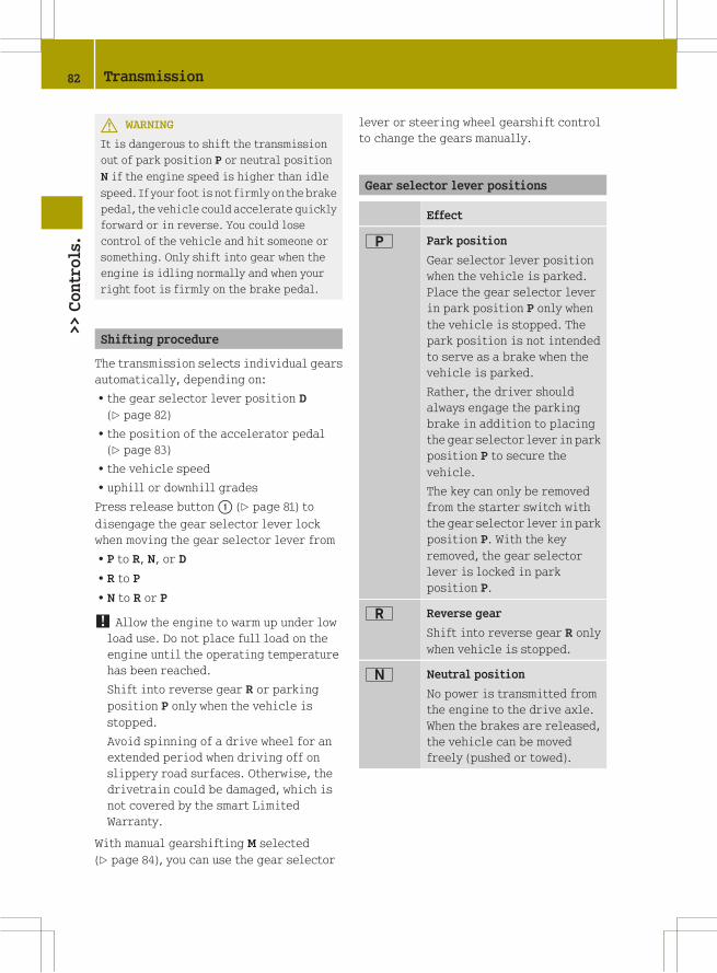
G WARNING
It is dangerous to shift the transmission
out of park position P or neutral position
N if the engine speed is higher than idle
speed. If your foot is not firmly on the brake
pedal, the vehicle could accelerate quickly
forward or in reverse. You could lose
control of the vehicle and hit someone or
something. Only shift into gear when the
engine is idling normally and when your
right foot is firmly on the brake pedal.
Shifting procedure
The transmission selects individual gears
automatically, depending on:
Rthe gear selector lever position D
(Y page 82)
Rthe position of the accelerator pedal
(Y page 83)
Rthe vehicle speed
Ruphill or downhill grades
Press release button: (Y page 81) to
disengage the gear selector lever lock
when moving the gear selector lever from
RP to R, N, or D
RR to P
RN to R or P
! Allow the engine to warm up under lowload use. Do not place full load on the
engine until the operating temperature
has been reached.
Shift into reverse gear R or parking
position P only when the vehicle is
stopped.
Avoid spinning of a drive wheel for an
extended period when driving off on
slippery road surfaces. Otherwise, the
drivetrain could be damaged, which is
not covered by the smart Limited
Warranty.
With manual gearshifting M selected
(Y page 84), you can use the gear selector
lever or steering wheel gearshift control
to change the gears manually.
Gear selector lever positions
Effect
B Park position
Gear selector lever position
when the vehicle is parked.
Place the gear selector lever
in park position P only when
the vehicle is stopped. The
park position is not intended
to serve as a brake when the
vehicle is parked.
Rather, the driver should
always engage the parking
brake in addition to placing
the gear selector lever in park
position P to secure the
vehicle.
The key can only be removed
from the starter switch with
the gear selector lever in park
position P. With the key
removed, the gear selector
lever is locked in park
position P.
C Reverse gear
Shift into reverse gear R only
when vehicle is stopped.
A Neutral position
No power is transmitted from
the engine to the drive axle.
When the brakes are released,
the vehicle can be moved
freely (pushed or towed).
82 Transmission>>Controls.

Effect
7 Drive position
The transmission shifts
automatically.
x Manual gearshifting
System-controlled automatic
gearshifting is switched off.
The driver has to change the
gears manually.
The current gear selector lever position
appears in the transmission position
indicator (Y page 87).
Driving tips
Accelerator pedal position
Your driving style influences the
transmission’s shifting behavior:
Less throttle earlier upshifting
More throttle later upshifting
Kickdown
Use kickdown when you want maximum
acceleration.
X Press the accelerator pedal past the
point of resistance.
Depending on the engine speed the
transmission shifts into a lower gear.
X Ease up on the accelerator pedal when you
have reached the desired speed.
The transmission shifts up again.
Stopping
When you stop briefly, e.g. at traffic
lights:
X Leave the transmission in gear.
X Hold the vehicle with the brake.
When you stop for a longer period with the
engine idling and/or on a hill:
X Engage the parking brake.
X Move the gear selector lever to park
position P.
Working on the vehicle
G WARNING
When working on the vehicle, engage the
parking brake and move the gear selector
lever to park position P. Otherwise the
vehicle could roll away which could result
in an accident and/or serious personal
injury.
Driving on uphill grades
G WARNING
The hill-start assist system is not
designed to function as a parking brake and
does not prevent the vehicle from moving
when parked on an incline.
Always engage the parking brake in
addition to shifting to park position P.
! When the hill‑start assist system stopsbraking the vehicle, it can roll
backwards.
If you open the driver’s door, the
hill‑start assist system is deactivated
and a warning signal sounds.
Your vehicle has a hill‑start assist system.
On uphill grades the hill‑start assist
system maintains the pressure in the brake
system for approximately one second after
you have released the brake pedal.
Therefore, you can start off smoothly
without the vehicle moving immediately
after releasing the brake pedal.
X Release the brake pedal.
X Apply sufficient pressure to the
accelerator pedal to drive off.
On uphill grades with higher inclination,
the hill-start assist system will release
the pressure in the brake system after
approximately two seconds. A warning
signal sounds and the transmission
Transmission 83
>>Controls.
Z

position indicator shows a flashing N in
order to warn you of the vehicle rolling
backwards.
X Press the brake pedal.
X Release the brake pedal.
X Apply sufficient pressure to the
accelerator pedal to drive off.
i The hill‑start assist system is inactiveif you start off with the parking brake
engaged.
Manual gearshifting
With manual gearshifting M selected,
system-controlled automatic gearshifting
is switched off and you need to change the
gears by upshifting or downshifting
manually using the gear selector lever or
the steering wheel gearshift control10.
! Allow the engine to warm up under lowload use. Do not place full load on the
engine until the operating temperature
has been reached.
Shift into reverse gear R or parking
position P only when the vehicle is
stopped.
Avoid spinning of a drive wheel for an
extended period when driving off on
slippery road surfaces. Otherwise, the
drivetrain could be damaged, which is
not covered by the smart Limited
Warranty.
Activating manual gearshifting
X Move the gear selector lever to drive
position D (Y page 81).
X Pull one of the shift paddles (Y page 84)
towards you.
or
X Move the gear selector lever to manual
gearshifting M (Y page 81).
System-controlled automatic
gearshifting is switched off.
You can upshift or downshift through the
gears in succession.
The currently engaged gear appears in the
multifunction display (Y page 84).
Upshifting
X Briefly push the gear selector lever
forward in the + direction (Y page 81).
or
X Pull right shift paddle; (Y page 84)
towards you.
The transmission shifts to the next
higher gear.
i With manual gearshifting M selected,
the transmission shifts up only to
prevent engine overrevving.
Downshifting
G WARNING
On slippery road surfaces, never downshift
in order to obtain braking action. This
could result in drive wheel slip and
reduced vehicle control. Your vehicle’s ABS
will not prevent this type of loss of control.
10 Model passion and BRABUS only.
84 Transmission>>Controls.
X Briefly pull the gear selector lever
backward in the - direction (Y page 81).
or
X Pull left shift paddle: (Y page 84)
towards you.
The transmission shifts to the next lower
gear.
Kickdown
You can use kickdown when you want
maximum acceleration.
X Press the accelerator pedal past the
point of resistance.
Depending on the engine speed the
transmission shifts into a lower gear.
X When you have reached the desired speed,
briefly push the gear selector lever
forward in the + direction (Y page 81).
or
X Pull right shift paddle; (Y page 84)
towards you.
The transmission shifts to the next
higher gear.
Deactivating manual gearshifting
X With drive position D selected: Pull and
hold right shift paddle; (Y page 84)
towards you for longer than two seconds.
or
X With manual gearshifting M selected:
Move the gear selector lever to drive
position D (Y page 81).
System-controlled automatic
gearshifting is switched on again.
Emergency operation (limp-home
mode)
In this mode only a certain gear or a
certain gear combination can be selected.
This mode is triggered in case of
transmission malfunctions and enables you
driving to the nearest workshop such as a
smart center.
If vehicle acceleration becomes less
responsive or sluggish or the transmission
no longer shifts, the transmission is most
likely operating in limp-home (emergency
operation) mode. The transmission
position indicator flashes and the¬
symbol appears in the multifunction
display.
Driving in limp-home mode:
X Move the gear selector lever to drive
position D (Y page 81).
X Continue to drive.
X Have the transmission checked at an
authorized smart center as soon as
possible.
i It is possible that a gear combinationincluding the reverse gear can not be
selected. Keep in mind when parking,
that reversing the vehicle might be
impossible.
In case of a minor transmission
malfunction, it might be possible to teach-
in the transmission in order to restore the
normal transmission mode.
i If the attempt to teach-in thetransmission fails, you cannot continue
to drive. Therefore we strongly
recommend that you have the
transmission taught-in at a qualified
workshop or at an authorized smart
center.
Teaching-in the transmission system:
X Stop the vehicle in a safe location.
X Move the gear selector lever to park
position P.
X Turn off the engine.
X Wait at least 30 seconds before
restarting.
X Press the brake pedal.
Transmission 85
>>Controls.
Z

X Restart the engine
Three bars instead of P appear in the
multifunction display.
X Wait at least 30 seconds.
The transmission is taught in.
When teaching-in was successful: P
appears in themultifunction display again
and normal transmission operating is
restored.
X Continue to drive.
After an unsuccessful teaching-in: Three
bars instead of P appear in the
multifunction display.
X Do not continue to drive.
X Turn off the engine.
X Engage the parking brake when leaving
the vehicle.
X Contact Roadside Assistance or an
authorized smart center.
Instrument cluster
Multifunction display
The following displays and indicators
appear in the multifunction display:
Multifunction display (U.S. vehicles)
: Maintenance service symbol (status
indicator)
; Main odometer display and days or
distance to next maintenance service
= Transmission position indicator
? Digital clock
A Outside temperature display
B Fuel level display
C Status indicator with:
• Trip odometer display
• Reserve fuel indicator
Multifunction display (Canada vehicles)
: Maintenance service symbol (status
indicator)
; Main odometer display and days or
distance to next maintenance service
= Transmission position indicator
? Digital clock
A Outside temperature display
B Freeze warning
C Fuel level display
D Status indicator with:
• Trip odometer display
• Reserve fuel indicator
G WARNING
No messages will be displayed if either the
instrument cluster or the multifunction
display is inoperative.
As a result, you will not be able to see
information about your driving
conditions, such as speed, outside
temperature, or warning/indicator lamps.
Driving characteristics may be impaired.
If you must continue to drive, please do so
with added caution. Visit an authorized
smart center as soon as possible.
86 Instrument cluster>>Controls.

Multifunction display illumination
The multifunction display illumination
comes on when the starter switch is in
position 1. It goes out after approximately
30 seconds when the starter switch is in
position 0.
For adjusting the multifunction display
illumination, see “Adjusting instrument
cluster illumination” (Y page 92).
Main odometer display
Example illustration (U.S. vehicles)
i Canada vehicles: The main odometerdisplay shows km instead of miles.
The main odometer display appears in the
multifunction display continuously.
Exception: The next maintenance service
is due. After starting the engine, days or
distance to next maintenance service will
appear instead of the main odometer
display. The main odometer display will
reappear after approximately ten seconds.
For information on how to select the
maintenance service interval display, see
“Maintenance service interval display”
(Y page 90).
Transmission position indicator
The following information is displayed in
the transmission position indicator:
RCurrent gear selector lever position
RCurrent engaged gear (when manual
gearshifting selected)
i A flashing R in the display indicatesthat the gear selector lever is in
position R but the reverse gear is not
engaged. Stop the vehicle to let the
reverse gear engage.
Example illustration (U.S. vehicles)
Display Function
P Gear selector lever in park
position P
R Gear selector lever in
position R (Reverse gear
engaged)
N Gear selector lever in neutral
position N
D Gear selector lever in drive
position D
When manual gearshifting is selected:
Display Function
1 First gear engaged
2 Second gear engaged
3 Third gear engaged
4 Fourth gear engaged
5 Fifth gear engaged
Instrument cluster 87
>>Controls.
Z

Digital clock
Example illustration (U.S. vehicles)
i Canada vehicles: The digital clockshows a 24 h-clock instead of a
12 h-clock.
The time can only be set as long as the colon
in the digital clock flashes.
X Activating time setting: Press and hold
right button; until the colon in the
digital clock starts flashing.
X Setting the time in 1 minute
increments: Press left button: or right
button; repeatedly until the desired
time is set.
X Setting the time quickly: Press left
button: or right button; for longer
than one second.
The setting speed increases.
X Setting the time in 10 minute
increments: Press left button: or right
button; for longer than five seconds.
The time is set in 10 minute increments.
X Confirm time setting: Refrain from
pressing either left button: or right
button; until the colon in the digital
clock stops flashing.
The time is set.
i The digital clock in the multifunctiondisplay is not synchronized with the
cockpit clock* (Y page 91).
Outside temperature display
G WARNING
The outside temperature display is not
designed as an ice-warning device and is
therefore unsuitable for that purpose.
Indicated temperatures just above the
freezing point do not guarantee that the
road surface is free of ice. The road may
still be icy, especially in wooded areas or
on bridges. Your vehicle could start to skid
if you do not adjust your driving style
accordingly.
Therefore, always adjust your driving style
to the prevailing road and weather
conditions.
Example illustration (U.S. vehicles)
i Canada vehicles: The outsidetemperature display shows °C instead
of °F.
The outside temperature display appears
in the multifunction display continuously.
A change of the outside temperature will be
displayed with delay.
88 Instrument cluster>>Controls.
* optional

Freeze warning (Canada vehicles only)
When the outside temperature falls below
3¥, the multifunction display makes you
aware of the fact that the road may be icy.
An additional freeze warning, i.e. an ice
crystal symbol, in the multifunction
display flashes. After 60 seconds, the
freeze warning stops flashing but
continues to be displayed. When the
outside temperature rises above 3¥, the
freeze warning goes out.
Fuel level display
Example illustration (U.S. vehicles)
The fuel level display shows the tank’s fuel
level with the aid of eight segments. The
number of dark segments indicates the fuel
level in the tank. If all eight segments are
dark, the tank is full.
You are driving on reserve fuel if there are
no more than 1.0 US gal (3.78 l) of fuel in the
tank.
If this occurs,
Rthe fuel pump symbol in the fuel level
display flashes
Rthe reserve fuel indicator shows the fuel
level in the tank in 0.1 US gal (0.5 l)
increments
For selecting the reserve fuel indicator to
be displayed in the status indicator, see
“Reserve fuel indicator” (Y page 91).
Selecting display for status indicator
You can select the information to be
displayed in the status indicator:
RTrip odometer display (Y page 90)
RMaintenance service interval display
(Y page 90)
RReserve fuel indicator (Y page 91)
(when less than 1.0 US gal (3.78 l) of fuel
is in the tank)
: Selecting display for status indicator,
setting the clock, activating
maintenance service interval display
; Setting the clock, adjusting instrument
cluster illumination
Instrument cluster 89
>>Controls.
Z

Trip odometer display
Example illustration (U.S. vehicles)
X Selecting trip odometer display: Press
left button: (Y page 89) repeatedly
until the trip odometer display appears
in the status indicator.
X Resetting trip odometer display: Press
and hold left button: (Y page 89) until
the value is set to 0.
Maintenance service interval display
Example illustration (U.S. vehicles)
i Canada vehicles: The maintenanceservice interval display shows km
instead of miles.
The maintenance service interval display
will notify you approximately one month
before the next maintenance service is
due.
The following information will be
displayed after starting the engine:
RDays or distance to next maintenance
service
This information will be displayed
instead of the main odometer display.
The main odometer display will reappear
after approximately ten seconds
(Y page 87).
RType of service that is due
This information will be displayed in
the status indicator.
X Start the engine.
X Selecting maintenance service interval
display: Press button: on the
instrument cluster repeatedly until the
maintenance service interval display
appears in the status indicator.
Depending on the type of maintenance
service that is due, symbol¬ or} is
displayed.
X Clearing maintenance service interval
display: Press button: once.
The maintenance service interval
display is cleared.
X Activating maintenance service
interval display: Press button: twice
in quick succession.
90 Instrument cluster>>Controls.

Reserve fuel indicator
Example illustration (U.S. vehicles)
The reserve fuel indicator is only
displayed when driving on reserve fuel.
X Selecting reserve fuel indicator: Press
button: on the instrument cluster
repeatedly until the reserve fuel
indicator appears in the status
indicator.
Auxiliary instruments*
: Tachometer
; Cockpit clock
Tachometer*
The tachometer displays the engine speed
in units of 1000 rpm.
The tachometer can be turned by
approximately 90°.
The tachometer illumination comes on when
you switch on the ignition and the exterior
lighting.
! Do not hang any objects on thetachometer.
This could cause the tachometer to be
torn from its mountings and damage it.
Cockpit clock*
The cockpit clock can be turned by
approximately 90°.
The cockpit clock illumination comes on
when you switch on the ignition and the
exterior lighting.
The buttons for setting the time are on the
top of the cockpit clock.
X Setting the time back in 1 minute
increments: Press button: repeatedly
until the desired time is set.
X Setting the time back quickly: Press
button: for longer than two seconds.
The setting speed accelerates.
X Setting the time forward in 1 minute
increments: Press button; repeatedly
until the desired time is set.
X Setting the time forward quickly: Press
button; for longer than two seconds.
The setting speed accelerates.
! Do not hang any objects on the cockpitclock.
This could cause the cockpit clock to be
torn from its mounting and damage it.
Instrument cluster 91
>>Controls.
* optional Z

Adjusting instrument cluster
illumination
You can adjust the illumination of the
switches, the dials in the instrument
cluster, the radio*, the climate control*
panel and the auxiliary instruments*. Five
illumination levels are available.
X Make sure the key is in starter switch
position 1.
X Switch on the parking lamps.
X To brighten or dim illumination: Press
button: on the instrument cluster
repeatedly until the desired setting is
reached.
The current setting is stored.
Control system*
Introduction
The control system is activated when you
turn the key in the starter switch to
position 1.
G WARNING
A driver’s attention to the road and traffic
conditions must always be his/her primary
focus when driving.
In order to avoid distraction which could
lead to an accident, the driver should
select features and change settings in the
control system only vehicle at a standstill
or when traffic and road conditions permit
it to be done safely.
Bear in mind that at a speed of just 30 mph
(approximately 50 km/h ), your vehicle is
covering a distance of 44 feet
(approximately 14 m) every second.
Control lever
You can select the displays in the
multifunction display and change settings
in the control system with the control
lever.
Control lever (example illustration coupé)
: Control switch
Pressing up selects a menu.
; OK button
Confirming a selection.
Scrolling through stored messages
in the Messages menu
= Control switch
Pressing down selects a menu.
Multifunction display
Themultifunction display shows values and
settings as well as display messages.
X Activating the multifunction display:
Turn the key to starter switch position 1.
X Confirming messages: Press the OK
button on the control lever (Y page 92)
briefly.
X Exitingmenu: Press the control switch on
the control lever (Y page 92) up or down
92 Control system*>>Controls.
* optional

until the message Back appears in the
multifunction display.
X Press the OK button on the control lever
briefly.
Control system* 93
>>Controls.
* optional Z
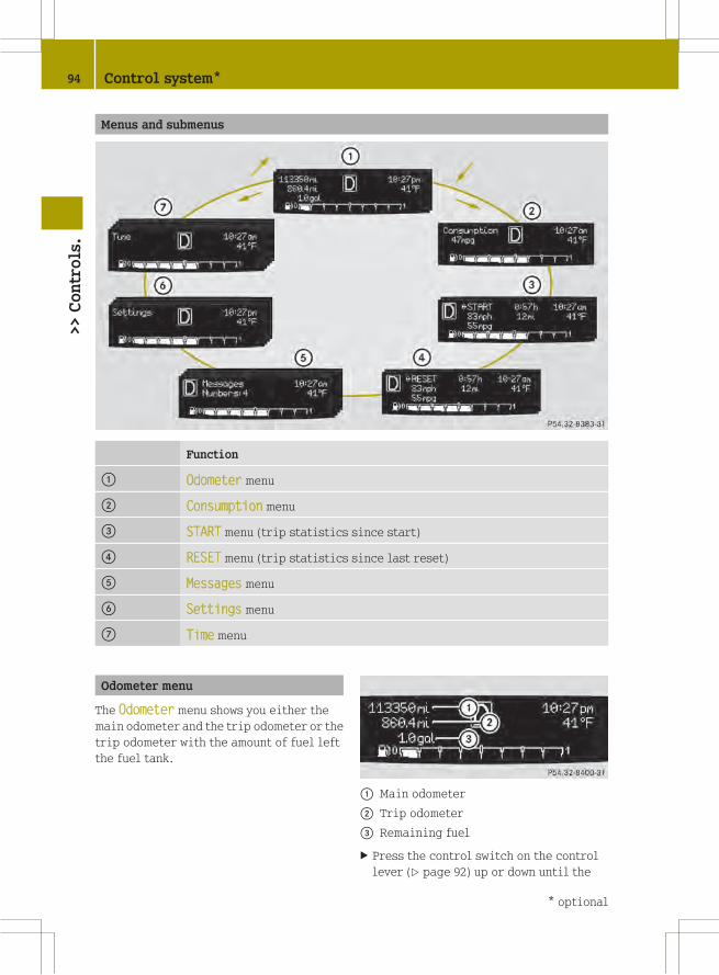
Menus and submenus
Function
: Odometer menu
; Consumption menu
= START menu (trip statistics since start)
? RESET menu (trip statistics since last reset)
A Messages menu
B Settings menu
C Time menu
Odometer menu
The Odometer menu shows you either the
main odometer and the trip odometer or the
trip odometer with the amount of fuel left
the fuel tank.
: Main odometer
; Trip odometer
= Remaining fuel
X Press the control switch on the control
lever (Y page 92) up or down until the
94 Control system*>>Controls.
* optional

Odometer menu appears in the
multifunction display.
X To switch between submenus: Press the OK
button on the control lever briefly.
X To reset the trip odometer: Select the
trip odometer display.
X Press button: (Y page 89) on the
instrument cluster until the trip
odometer is reset to 0.
Consumption menu
The Consumption menu shows you the
current fuel consumption.
X Press the control switch on the control
lever (Y page 92) up or down until the
Consumption menu appears in the
multifunction display.
The current current fuel consumption
appears.
i Depending on the selected unit in thesettings menu (Y page 96), the
consumption is displayed in inmiles per
gallon (mpg) or in liters per 100
kilometers (l/100 km).
Canada only: When the vehicle is
standing, the fuel consumption is
displayed in gallons per hour (gal/h) or
liters per hour (l/h).
Start menu
The START menu menu shows you the trip
statistics since start.
: Average speed since start
; Time elapsed since start
= Distance driven since start
? Average fuel consumption since start
X Press the control switch on the control
lever (Y page 92) up or down until the
STARTmenu appears in the multifunction
display.
X To reset: Press button: (Y page 89) on
the instrument cluster until the START
menu is reset to 0.
i The START menu is reset to 0automatically
Rwhen the ignition has been switched
off for more than 4 hours
Rafter driving more than 9999 miles or
kilometers
Reset menu
The RESET menu menu shows you the trip
statistics since the last reset.
: Average speed since last reset
; Time elapsed since since last reset
= Distance driven since last reset
? Average fuel consumption since since
last reset
X Press the control switch on the control
lever (Y page 92) up or down until the
Control system* 95
>>Controls.
* optional Z
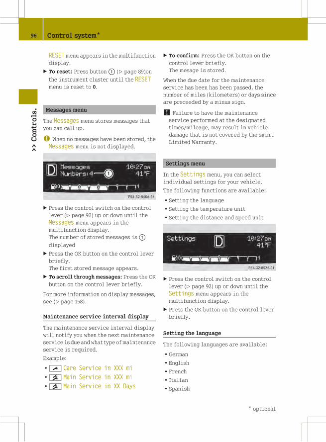
RESETmenu appears in the multifunction
display.
X To reset: Press button: (Y page 89)on
the instrument cluster until the RESET
menu is reset to 0.
Messages menu
The Messages menu stores messages that
you can call up.
i When no messages have been stored, theMessages menu is not displayed.
X Press the control switch on the control
lever (Y page 92) up or down until the
Messages menu appears in the
multifunction display.
The number of stored messages is:
displayed
X Press the OK button on the control lever
briefly.
The first stored message appears.
X To scroll through messages: Press the OK
button on the control lever briefly.
For more information on display messages,
see (Y page 158).
Maintenance service interval display
The maintenance service interval display
will notify you when the next maintenance
service is due andwhat type ofmaintenance
service is required.
Example:
R¯ Care Service in XXX mi
R° Main Service in XXX mi
R° Main Service in XX Days
X To confirm: Press the OK button on the
control lever briefly.
The mesage is stored.
When the due date for the maintenance
service has been has been passed, the
number of miles (kilometers) or days since
are preceeded by a minus sign.
! Failure to have the maintenanceservice performed at the designated
times/mileage, may result in vehicle
damage that is not covered by the smart
Limited Warranty.
Settings menu
In the Settings menu, you can select
individual settings for your vehicle.
The following functions are available:
RSetting the language
RSetting the temperature unit
RSetting the distance and speed unit
X Press the control switch on the control
lever (Y page 92) up or down until the
Settings menu appears in the
multifunction display.
X Press the OK button on the control lever
briefly.
Setting the language
The following languages are available:
RGerman
REnglish
RFrench
RItalian
RSpanish
96 Control system*>>Controls.
* optional

X Press the control switch on the control
lever (Y page 92) up or down until the
Language submenu appears in the
multifunction display.
X Press the OK button on the control lever
briefly.
X Press the control switch on the control
lever (Y page 92) up or down until the
desired language is selected.
X Press the OK button on the control lever
briefly to confirm.
The selected language is stored.
Setting the temperature unit
The following units are available:
R†
R‡
X Press the control switch on the control
lever (Y page 92) up or down until the
°F/°C submenu appears in the
multifunction display.
X Press the OK button on the control lever
briefly.
X Press the control switch on the control
lever (Y page 92) up or down until the
desired unit is selected.
X Press the OK button on the control lever
briefly to confirm.
The selected unit is stored.
Setting the distance and speed unit
The following units are available:
RMiles (mi)
RKilometers (km)
X Press the control switch on the control
lever (Y page 92) up or down until the mi–
km submenu appears in the multifunction
display.
X Press the OK button on the control lever
briefly.
X Press the control switch on the control
lever (Y page 92) up or down until the
desired unit is selected.
X Press the OK button on the control lever
briefly to confirm.
The selected unit is stored.
i Canada only: The unit for the cruisecontrol (Y page 100) does not change,
regardless of which unit is set in this
menu.
Time menu
The Time menu lets you set the time and
offers different display modes.
The following submenus are available:
RSetting time display mode (12-hour or
24-hour mode)
RSetting period of day, am or pm11
RSetting the hours
RSetting the minutes
X Press the control switch on the control
lever (Y page 92) up or down until the
Time menu appears in the multifunction
display.
X Press the OK button on the control lever
briefly.
Setting the time display mode
X Press the control switch on the control
lever (Y page 92) up or down until the
12h 24h submenu appears in the
multifunction display.
X Press the OK button on the control lever
briefly.
X Press the control switch on the control
lever (Y page 92) up or down until the
desired setting is selected.
X Press the OK button on the control lever
briefly to confirm.
The selected mode is stored.
11 Only available in 12-hour mode.
Control system* 97
>>Controls.
* optional Z

Setting the period of day
X Press the control switch on the control
lever (Y page 92) up or down until the
am pm submenu appears in the
multifunction display.
X Press the OK button on the control lever
briefly.
X Press the control switch on the control
lever (Y page 92) up or down until the
desired setting is selected.
X Press the OK button on the control lever
briefly to confirm.
The selected mode is stored.
Setting the hours
X Press the control switch on the control
lever (Y page 92) up or down until the
Hour submenu appears in the
multifunction display.
X Press the OK button on the control lever
briefly.
X Press the control switch on the control
lever (Y page 92) up or down until the
desired setting is selected.
X Press the OK button on the control lever
briefly to confirm.
The selected hours are stored.
Setting the minutes
X Press the control switch on the control
lever (Y page 92) up or down until the
Minute submenu appears in the
multifunction display.
X Press the OK button on the control lever
briefly.
X Press the control switch on the control
lever (Y page 92) up or down until the
desired setting is selected.
X Press the OK button on the control lever
briefly to confirm.
The selected minutes are stored.
Audio system*
G WARNING
In order to avoid distraction which could
lead to an accident, the driver should enter
system settings with the vehicle at a
standstill and operate the system only when
road and traffic conditions permit. Always
pay full attention to traffic conditions
first before operating system controls
while driving.
Bear in mind that at a speed of just 30 mph
(approximately 50 km/h), your vehicle is
covering a distance of 44 feet
(approximately 14 m) every second.
G WARNING
Always select a volume that allows you to
still hear ambient sound in your immediate
vicinity (e.g. horns, emergency rescue
vehicles, police vehicles, etc.). You could
otherwise cause an accident.
G WARNING
If you wish to have an audio system other
than an original smart audio system fitted
in your vehicle, please always have the
necessary work performed at an authorized
smart center.
This is particularly important if your
vehicle is fitted with a radio
preinstallation. Improper connection can
result in the failure of important vehicle
functions, thereby endangering the
operating safety of your vehicle and thus
your own safety and that of other people.
The following pages contain a brief
description of the audio systems available
for the coupé and cabriolet.
The devices are described with their full
complement of equipment. The description
for your individual equipment
specification applies.
Please refer to the separate operating
instructions for detailed functions.
98 Audio system*>>Controls.
* optional

Audio system basic*
The audio system basic contains the
following functions:
RRadio (FM/AM)
RRadio Broadcast Data System (RBDS) and
radio text
RAUX and USB socket (Y page 99)
! Please be sure to read the operatinginstructions for the audio system basic
before using the unit. Familiarize
yourself with the various functions of the
unit so that you are able to operate it
easily, reliably and correctly at any
time.
: On/off and volume switch
; Display
= Skip/Scroll/Frequency search switches
? Tone settings/Mute/Back control panel
A Stored station buttons
B Radio/Media/System control panel
Audio system navigation/multimedia*
The audio system navigation/multimedia
contains the following functions:
RRadio (FM/AM)
RRadio Broadcast Data System (RBDS)
RAUX and USB-socket
RBluetooth® hands-free device
RNavigation
RAudio operation from CD/DVD or SD Card,
via AUX/USB/iPod®, or Bluetooth® Audio
RVideo operation from CD/DVD or SD Card,
via AUX/USB/iPod®
RImage display from CD/DVD or SD Card,
via USB/iPod®
! Please be sure to read the operatinginstructions for the audio system
navigation/multimedia before using the
unit. Familiarize yourself with the
various functions of the unit so that you
are able to operate it easily, reliably
and correctly at any time.
: Bluetooth® connection indicator lamp
; Display
= Microphone
? Light sensor
A Eject button
B Rotary/Push button
C Menu button
AUX and USB sockets*
You can connect mobile audio devices such
as an MP3 player via the AUX and USB
sockets using commercially available
3.5 mm socket plug (AUX) or USB connector
cable (USB).
The AUX and USB sockets are located in the
glove box.
Audio system* 99
>>Controls.
* optional Z

: USB socket
; AUX socket
smart surround sound system*
The smart surround sound system
supplements the existing speakers with
more powerful and additional speakers
(including a digital amplifier in the
passenger footwell and a passive
subwoofer).
Driving systems
Cruise control*
The cruise control maintains the speed you
set for your vehicle automatically. On
downhill grades, the cruise control does
not brake the vehicle via the brake system.
The cruise control can only use the braking
power of the engine. You must apply the
brakes yourself in order to reduce the
vehicle speed. The cruise control will then
be canceled.
G WARNING
The cruise control is a convenience system
designed to assist the driver during
vehicle operation. The cruise control
cannot take road, traffic, and weather
conditions into account. The driver is and
must always remain responsible for the
vehicle’s speed and for safe brake
operation.
Do not use the cruise control
Rif the road, traffic, and weather
conditions do not make it advisable to
travel at a constant speed
Ron slippery roads
Rapid changes in tire traction can result
in wheel spin and loss of control.
Rwhen driving in fog
The use of the cruise control is
recommended for driving at a constant
speed for extended periods of time.
With the cruise control is activated and a
speed set, the following message appears
in the multifunction display:
U.S. vehicles
: Cruise control activated
; Speed has been set
Canada vehicles
: Cruise control activated
; Set speed
The cruise control is operated via buttons
on the steering wheel.
100 Driving systems>>Controls.
* optional

: Activating or deactivating the cruise
control
; Resuming at last set speed or
increasing speed
= Setting current or lower speed, or
decreasing speed
? Canceling the cruise control
Activating/deactivating
The cruise controlmust be activated before
you can set a speed. When you turn off the
engine, the cruise control is deactivated
automatically.
X Press ON/OFF button: briefly.
The cruise control is activated.
CRUISE (USA only) orV (Canada only)
appears in the multifunction display.
Setting current speed
You can set any speed above 20 mph
(30 km/h).
X Accelerate the vehicle to the desired
speed.
X With the cruise control activated, press
SET/− button= briefly.
X Remove your foot from the accelerator
pedal.
The current speed is set and the vehicle
maintains that speed.
USA only: set appears in the
multifunction display to indicate that
the speed has been set.
Canada only: The set speed appears in the
multifunction display next to cruise
control symbolV.
i On uphill grades, the cruise controlmay not be able tomaintain the set speed.
Once the grade eases, the set speed will
be resumed.
On downhill grades, the cruise control
can only maintain the set speed using the
engine’s braking power. You must apply
the brakes yourself when the vehicle does
not slow down sufficiently. This will
cancel the cruise control.
Canceling cruise control
When the cruise control is activated, you
can cancel it at any time and resume the set
speed later.
X Press CANCEL button? briefly.
or
X Depress the brake pedal.
The cruise control is canceled.
The cruise control deactivates
automatically, when
Ryou depress the brake pedal
Rthe vehicle speed is below 20 mphh
(30 km/h)
RESP® is in operation.
Resuming last set speed
G WARNING
The “Resume” function should only be
operated if the driver is fully aware of the
previously set speed and wishes to resume
this particular preset speed.
The set speed stored in memory should only
be set again if prevailing road conditions
and legal speed limits permit. Possible
acceleration or deceleration differences
arising from returning to the preset speed
could cause an accident and/or serious
injury to you and others.
Driving systems 101
>>Controls.
Z

X Press RES/+ button; briefly.
The cruise control resumes the
previously set speed.
i The last set speed stored in memory isdeleted when the engine is turned off.
Changing the set speed
You must have set a speed prior to
increasing or decreasing the current
speed.
i Depressing the accelerator pedal doesnot deactivate the cruise control. After
a brief acceleration (e.g. for passing),
the cruise control will resume the last
set speed.
Continuous adjustment
X Press and hold RES/+ button; to
increase the speed.
or
X Press and hold SET/−= to decrease the
speed.
X Press and hold the respective button
until the desired speed is reached.
X Release the respective button.
The new speed is stored.
Adjustment in 1 mph (Canada 1 km/h)
increments
X Press RES/+ button;briefly to increase
the speed.
or
X Press SET/−= briefly to decrease the
speed.
The new speed is stored after releasing the
respective button.
HVAC (Heating, Ventilation, Air
Conditioning)
Notes on HVAC
G WARNING
Follow the recommended settings for
heating and cooling given on the following
pages. Otherwise the windows could fog up,
impairing visibility and endangering you
and others.
Air conditioning with climate control*
The air conditioning improves the level of
comfort when driving at high outside
temperatures by cooling and
dehumidifying the air.
Nearly all dust particles, pollutants, are
filtered out by an integrated particle
filter before outside air enters the
passenger compartment through the air
distribution system. It also operates when
the air conditioning is switched off and
you have switched on the blower.
The air conditioning only works when the
engine is running and the blower is
switched on. Maximum effectiveness is
achieved if you drive with the windows
closed.
i In warmer weather, ventilate thepassenger compartment for a short
period of time before utilizing the air
conditioning.
102 HVAC (Heating, Ventilation, Air Conditioning)>>Controls.
* optional

Control panels HVAC
Heating
: Air volume control
; Rear window defroster switch
= Air distribution control
? Temperature control
Air conditioning with climate control*
: Air volume control
; Air conditioning switch
= Rear window defroster switch
? Air recirculation switch
A Temperature control
B Air distribution control
Switching HVAC on/off
Heating
Control panel (Y page 103).
X Switching on: Make sure the key is in
starter switch position 1.
X Push temperature control? up.
X Switching off: Push temperature
control? fully down.
HVAC (Heating, Ventilation, Air Conditioning) 103
>>Controls.
* optional Z
Air conditioning with climate control*
Control panel (Y page 103).
X Make sure the engine is running.
X Switching on: Push air volume
control: to level 1 or higher.
X Press air conditioning switch;.
The indicator lamp in air conditioning
switch; comes on.
X Switching off: Press air conditioning
switch; once more.
The indicator lamp in air conditioning
switch; goes out.
i The stored status is restored, if youswitch on the ignition again.
i The air condition will be suspended
temporarily:
Rif the engine speed is too low
Rwhen driving off
The air condition is switched off:
Rat a coolant temperature of more than
239¦ (115¥)
Rat outside temperatures below 38¦
(3¥)
Setting the temperature
Heating
Control panel (Y page 103).
i You should raise or lower thetemperature setting in small
increments.
X Increasing or decreasing: Push
temperature control? up or down.
Rapid cooling
X Push air volume control: fully up.
X Turn air distribution control= to
positionP.
X Push temperature control? fully down.
X Adjust the air vents as desired.
Rapid heating
X Push air volume control: to level 3.
X Turn air distribution control= to a
position betweenz andO.
X Push temperature control? fully up.
X Adjust the air vents towards the
occupants.
Air conditioning with climate control*
Control panel (Y page 103).
i You should raise or lower thetemperature setting in small
increments, preferably starting at
70¦ (21¥).
X Increasing or decreasing: Push
temperature controlA up or down.
Adjusting air vents
G WARNING
When operating the heating or air
conditioning with climate control*, the
air that enters the passenger compartment
through the air vents can be very hot or very
cold (depending on the set temperature).
This may cause burns or frostbite on
unprotected skin in the immediate area of
the air vents. Always keep sufficient
distance between unprotected parts of the
body and the air vents. If necessary, use the
air distribution control to direct the air
to air vents in the vehicle interior that are
not in the immediate area of unprotected
skin.
To make sure the heating or air
conditioning with climate control* works
properly, please observe the following:
RKeep the air intake grill free from
deposits, e.g. ice or snow, to ensure that
104 HVAC (Heating, Ventilation, Air Conditioning)>>Controls.
* optional

fresh air can flow freely into the vehicle
interior.
RDo not obstruct air vents or ventilation
grilles in the vehicle interior.
i For draft-free ventilation, move thesliders for the center air vents and side
air vents to the middle position.
Center air vents
: Left center air vent, adjustable
; Right center air vent, adjustable
X Adjusting: Turn slider: or; to the
left, right, up, or down.
X Opening: Turn slider: or; inwards
towards the center console.
X Closing: Turn slider: or; fully
outwards towards the side window.
Side air vents
Side air vents on driver’s side illustrated asexample
: Left side air vent, adjustable
; Left side defroster air vent, fixed
X Adjusting: Turn slider: to the left,
right, up, or down.
X Opening: Turn slider: inwards towards
the center console.
X Closing: Turn slider: fully outwards
towards the side window.
Adjusting air distribution
Symbol Function
z Directs air to the windshield
and side windows
O Directs air to the footwells
and air distribution is
reduced at the center and side
air vents
P Directs air through the center
and side air vents
i You can also turn the air distributioncontrol to a position between two
symbols.
Heating
Control panel (Y page 103).
X Turn air distribution control= to the
desired symbol.
The air distribution is controlled
depending on the position of the air
distribution control.
Air conditioning with climate control
Control panel (Y page 103).
X Turn air distribution controlB to the
desired symbol.
The air distribution is controlled
depending on the position of the air
distribution control.
HVAC (Heating, Ventilation, Air Conditioning) 105
>>Controls.
Z

Adjusting air volume
The air volume is controlled depending on
the blower speed selected. Five blower
speeds are available.
0 Off
1 Slow
2 Medium
3 High/defrosting
4 Maximum
X Increasing or decreasing: Push air
volume control: up or down.
Defrosting
G WARNING
Never drive with iced up or fogged
windows. Visibility will be significantly
impaired. Impaired visibility could
endanger yourself and others. This may
prevent you from observing the traffic
conditions, thereby causing an accident.
The best defrosting of windows is achieved
if the ice is completely removed from the
windows manually with an ice scraper
before starting the engine.
Heating
Control panel (Y page 103).
X Switching on: Push air volume
control: to level 3.
X Turn air distribution control= to
positionz.
X Push temperature control? fully up.
Air conditioning with climate control
Control panel (Y page 103).
X Switching on: Push air volume
control: to level 3.
X Turn air distribution controlB to
positionz.
X Push temperature controlA fully up.
Rear window defroster
The rear window defroster serves to de-ice
the rear window quickly and clear the view
if the rear window is fogged.
The rear window defroster uses a large
amount of power. To keep battery drain to a
minimum, switch off the rear window
defroster as soon as the rear window is
clear. The rear window defroster is
automatically deactivated after
approximately 10 minutes of operation.
X Make sure the key is in starter switch
position 1.
X Switching on: Press rear window
defroster switch:.
The indicator lamp in rear window
defroster switch: comes on.
X Switching off: Press rear window
defroster switch: once more.
The indicator lamp in rear window
defroster switch: goes out.
106 HVAC (Heating, Ventilation, Air Conditioning)>>Controls.
* optional

Air recirculation mode*
Switch to air recirculation mode12 to
prevent unpleasant odors from entering the
vehicle from the outside (e.g. before
driving through a tunnel). This setting cuts
off the intake of outside air and
recirculates the air in the passenger
compartment.
G WARNING
When the air recirculation mode is
switched on, windows can fog on the inside
immediately. Fogged windows impair
visibility, endangering you and others. If
the windows begin to fog on the inside,
switching off the air recirculation mode
immediately should clear interior window
fogging. If interior window fogging
persists, make sure the air conditioning is
switched on, turn air distribution control
B to positionz and increase the air
volume using air volume control:.
Control panel (Y page 103).
X Switching on: Press air recirculation
switch?.
The indicator lamp in air recirculation
switch? comes on.
X Switching off: Press air recirculation
switch? once more.
The indicator lamp in air recirculation
switch? goes out.
Loading and storing
Cup holder
G WARNING
In order to help prevent spilling liquids
on vehicle occupants and/or vehicle
equipment, only use containers that fit
into the cup holder. Use lids on open
containers and do not fill containers to a
height where the contents, especially hot
liquids, could spill during braking,
vehicle maneuvers, or an accident. Liquids
spilled on vehicle occupants may cause
serious personal injury. Liquids spilled
on vehicle equipment may cause damage not
covered by the smart Limited Warranty.
Keep in mind that objects placed in a cup
holder may come loose during braking,
vehicle maneuvers, or an accident and be
thrown around in the vehicle interior.
Objects thrown around in the vehicle
interior may cause an accident and/or
serious personal injury.
The cup holder can be used to safely store
sealed drink bottles, containers with a lid,
or beverage cans.
! Do not use the cup holder as an ashtray.Otherwise it could be damaged.
You can store two cups, drink bottles or
beverage cans in cup holder:.
i Clean the cup holder with a damp cloth.
Cargo compartment cover blind with
parcel net bag
This feature is only available in Canada
for the model passion.
G WARNING
The cargo compartment cover blind is not
intended to secure heavy objects in the
12 Vehicles with air conditioning with climate control* only.
Loading and storing 107
>>Controls.
* optional Z

event of an accident. For this reason, heavy
objects must be tied down.
Vehicle occupants could be injured by
objects being thrown around in the vehicle
in the event of
Rhard braking
Ra change of direction
Ran accident
G WARNING
Do not place any objects on the mounted
cargo compartment cover blind.
Vehicle occupants could be injured by
objects being thrown around in the vehicle
in the event of
Rhard braking
Ra change of direction
Ran accident
G WARNING
Only place light loads in the parcel net
bag. Do not transport heavy, sharp-edged or
fragile objects in the parcel net bag. The
parcel net bag cannot sufficiently secure
loads in an accident.
Vehicle occupants could be injured by
objects being thrown around in the vehicle
in the event of
Rhard braking
Ra change of direction
Ran accident
Observe the loading guidelines.
The cargo compartment cover blind
Rserves to protect objects that are stored
in the vehicle’s cargo compartment from
prying eyes
Rprevents smaller objects from
penetrating into the passenger
compartment from the cargo
compartment; however, it is not intended
to act as a load restraining device
The parcel net bag
Ris for storing small, lightweight objects
Rprevents small objects from sliding
around inside the passenger
compartment
! If objects are placed on the cargocompartment cover blind when mounted,
the cover may be damaged.
Fitting
If you wish to use cargo compartment cover
blind: as normal, assemble it in top
mountings;. If you do not need the cargo
compartment cover blind, insert in bottom
mountings=.
X Open the tailgate.
X Secure cargo compartment cover
blind: at the front of the cargo
compartment with the parcel net bag.
X Insert cargo compartment cover
blind: on the right-hand side in top
mounting; or in bottom mounting=.
108 Loading and storing>>Controls.

X Push handle? to the right in the
direction of the arrow.
X Insert cargo compartment cover
blind: in top mounting; or bottom
mounting= in the left-hand side
paneling and release handle?.
X Cargo compartment cover blind:
engages.
X Pull parcel net bagA down slightly and
secure with the hook and loop fastener.
X Remove in reverse order.
Controls
X Closing: Take hold of cargo compartment
cover blind: in the middle and pull
backwards.
X Guide cargo compartment cover
blind: into the rear right and left
mountings;.
X Opening: Take hold of cargo compartment
cover blind: in the middle, pull
backwards, and remove from rear
mountings;.
X Guide cargo compartment cover
blind: into position.
Coat hooks
The coat hooks are located at the rear roof
rail on the driver’s and passenger side.
Coat hook on driver’s side
: Coat hook
Storage compartments
G WARNING
To help avoid personal injury during a
collision or sudden maneuver, exercise
care when storing objects in the vehicle.
Put luggage or cargo in the cargo
compartment if possible. Do not pile
luggage or cargo higher than the seat
backrests.
Keep compartment lids closed. This will
help to prevent stored objects from being
thrown about and injuring vehicle
occupants during
Rhard braking
Ra change of direction
Ran accident
Do not store objects under the driver’s seat.
Objects stored under the driver’s seat can
slide forward into driver’s foot well during
braking and get caught between or beneath
Loading and storing 109
>>Controls.
Z

the pedals. This could restrict your ability
to brake or accelerate and could lead to
accidents and injury.
Coin holder
The coin holder is located in front of the
gear selector lever.
Example illustration (coupé)
: Coin holder
Door pockets
The door pockets are located in the driver’s
and passenger door.
: Door pocket
Storage trays next to the steering wheel
The storage trays are located to the left and
right of the steering wheel.
: Storage tray
Glove box
i A clamp rail for slips of paper islocated on the outside of the glove box
lid.
X Opening: Pull on glove box lid
release: and fold down the glove box
lid.
X Closing: Lift up the glove box lid with a
bit of force until it engages.
X Locking: Insert the key into the glove box
lock and turn it to position3.
X Unlocking: Insert the key into the glove
box lock and turn it to position2.
110 Loading and storing>>Controls.

Storage tray* in center console
X Installing: Slide storage tray; onto the
cones on the center console until it
engages audibly.
X Removing: Press levers:
simultaneously towards the storage tray.
X Pull storage tray; away from the center
console.
X Opening: Pull handle=.
X Closing: Swivel storage tray; back
until it engages.
Parcel nets
Parcel nets are located on the in-board
sides of the seat backrests.
i Vehicles equipped with an armrest* onthe driver’s seat, have a parcel net on the
passenger seat only.
i Each parcel net is intended for light-weight items of below 0.9 lb (0.4 kg).
Example illustration: Parcel net on passengerseat
: Parcel net
Drawer*
A drawer is located below the audio
system*13.
X Opening: Press on the center of
drawer:.
The drawer opens slightly.
X Pull drawer: to open completely.
X Closing: Press on drawer: until it
engages.
Storage compartment in the tailgate
(coupé only)
You can store small objects in the storage
compartment in the tailgate.
13 Vehicles with audio system basic* only.
Loading and storing 111
>>Controls.
* optional Z

X Opening: Open the tailgates.
X Pull handle: on the inside of the
tailgate backward.
X Lift up the storage compartment cover.
X Closing: Close storage compartment
cover:.
X Press on the “PRESS” marking in the
middle of storage compartment cover:
until it engages audibly.
X Close the tailgates (Y page 55).
Loading instructions
G WARNING
Transport heavy or hard objects in the
cargo compartment, not in the passenger
compartment.
Always fasten items being carried as
securely as possible using fastening
materials appropriate for the weight and
size of the load.
In an accident, during hard braking or
sudden maneuvers, loose items may be
thrown around inside the vehicle, causing
injury to vehicle occupants.
G WARNING
To help avoid personal injury during a
collision or sudden maneuver, exercise
care when storing objects in the vehicle.
Put luggage or cargo in the cargo
compartment if possible. Do not pile
luggage or cargo higher than the seat
backrests.
Keep compartment lids closed. This will
help to prevent stored objects from being
thrown about and injuring vehicle
occupants during
Rbraking
Rvehicle maneuvers
Ran accident
G WARNING
No racks or loads may be secured to the roof
of the vehicle, as
Rthe panorama roof* may be damaged, thus
injuring persons
Rthis can have a substantial adverse
effect on the driving dynamics of the
vehicle, thus causing accidents
Rthe rack and/or the load could detach and
through this cause an accident or other
people could be injured by the load and/
or rack that has fallen off
G WARNING
Make sure the tailgate is closed when the
engine is running and while driving.
Among other dangers, deadly carbon
monoxide (CO) gases may enter vehicle
interior resulting in unconsciousness and
death.
G WARNING
Do not store any flammable substances
inside the vehicle that could ignite and
start a fire.
G WARNING
The manufacturer has not approved your
vehicle for towing a trailer. A trailer can
permanently impair driving safety.
The gross vehicle weight which is the
weight of the vehicle including fuel, tools,
installed accessories, passengers, and
luggage/cargo must never exceed the load
limit and the Gross Vehicle Weight Rating
(GVWR) for your vehicle as specified on the
placard located on the driver’s door
112 Loading and storing>>Controls.
* optional

B‑pillar (Y page 214). In addition, the
load must be distributed in such a way so
that the weight on each axle never exceeds
the Gross Axle Weight Rating (GAWR) for the
front and rear axle. The GVWR and GAWR for
your vehicle are indicated on the
certification label which can be found on
the driver’s door B‑pillar.
For more information, see “Loading the
vehicle” (Y page 130).
The handling characteristics of a fully
loaded vehicle depend greatly on the load
distribution. It is therefore recommended
to load the vehicle with the heaviest items
being placed towards the front of the
vehicle.
Please pay attention to and comply with the
following instructions when loading the
vehicle and transporting cargo:
RAlways place items being carried
against seat backrests, and fasten them
as securely as possible.
RThe heaviest portion of the cargo should
always be kept as low as possible against
seat backrests.
RDo not stack loads higher than the top
edge of the head restraints.
RMake sure no luggage/cargo items can get
above or next to the driver’s and/or
passenger seat into the passenger
compartment.
RMake sure luggage/cargo is properly
secured.
RAlways use, if so equipped, cargo net*
when transporting cargo.
Do not carry any unnecessary weight in the
vehicle. This increases vehicle weight,
which results in increased energy
consumption.
Useful features
Sun visors
The sun visors protect you from sun glare
while driving.
Glare through the windshield
X Swing sun visor: down.
Glare through a side window
X Swing sun visor: down.
X Disengage sun visor: from
mounting;.
X Pivot sun visor: to the side.
Sun screen*
The sun screen provides protection from
sun rays and from heat generated by the
panorama roof*.
The sun screen can be adjusted to any
desired position.
X Opening or closing: Move sun screen:
forward or backward using the handle.
Useful features 113
>>Controls.
* optional Z

Auxiliary power outlet
The auxiliary power outlet supplies power
to the following electrical accessories
when the key is turned to starter switch
position 1:
Rthe cigarette lighter*, available in
conjunction with the ashtray*
Rthe electric air pump, available in
conjunction with the tire repair kit*
Rother consumers which operate up to a
maximum of 60 W
! The auxiliary power outlet canaccommodate 12V DC electrical
accessories designed for use with the
standard “cigarette lighter” plug type.
Keep in mind, however, that connecting
accessories to the auxiliary power outlet
(for example extensive connecting and
disconnecting, or using plugs that do not
fit properly) can damage the auxiliary
power outlet. With the auxiliary power
outlet damaged, the cigarette lighter*
may no longer be able to be placed in the
heating (pushed-in) position, or may pop
out before it is hot enough.
The auxiliary power outlet is located in the
lower center console.
Auxiliary power outlet
X Turn the key to starter switch position 1.
! Please observe the safety instructionsgiven in the respective operating
instructions.
Please note that
Rif using the auxiliary power outlet the
maximum current drawn may not exceed
5 A or 60 W
Rthe electric air pump* can be connected
to the auxiliary power outlet for the time
it takes to inflate the tire without any
problem
Rthe vehicle battery will discharge when
current is drawn.
114 Useful features>>Controls.
* optional

>>Operation.
The first 1000 miles (1500 km) .............. 116
At the gas station ............................. 116
Engine compartment .......................... 117
Front compartment ........................... 120
Tires and wheels .............................. 124
Winter driving ................................ 143
Driving instructions ........................ 144
Driving abroad ................................ 151
Vehicle care ................................... 151

The first 1000 miles (1500 km)
In the Operation section you will find
detailed information on operating,
maintaining and caring for your vehicle.
The more cautiously you treat your vehicle
during the break-in period, the more
satisfied you will be with its performance
later on.
RDrive your vehicle during the first
1000 miles (1 500 km) at varying but
moderate vehicle and engine speeds.
RDuring this period, avoid heavy loads
(full throttle driving) and excessive
engine speeds (no more than 2/3 of
maximum rpm in each gear).
RShift gears in a timely manner.
RDo not attempt to slow the vehicle down
by shifting to a lower gear.
RAvoid accelerating by kickdown.
After 1000 miles (1 500 km), you may
gradually increase vehicle and engine
speeds to the permissible maximum.
All of the above instructions also apply
when driving the first 1000 miles (1500 km)
after the engine has been replaced.
i Always obey applicable speed limits.
At the gas station
Refueling
G WARNING
Gasoline is highly flammable and
poisonous. It burns violently and can cause
serious personal injury.
Never allow sparks, flame or smoking
materials near gasoline!
Turn off the engine before refueling.
Whenever you are around gasoline, avoid
inhaling fumes and skin or clothing
contact. Extinguish all smoking materials.
Direct skin contact with fuels and the
inhalation of fuel vapors are damaging to
your health.
! Do not put diesel fuel in vehicles withgasoline engines. Do not mix gasoline
with diesel fuel. Even small quantities
of diesel fuel will damage the injection
system. Damage caused by adding diesel
fuel will not be covered by the smart
Limited Warranty.
If diesel fuel has mixed with gasoline,
do not start the engine. Otherwise the
catalytic converter will be irreparably
damaged.
Contact an authorized smart center or
Roadside Assistance immediately and
have the vehicle towed.
! Damage resulting frommixing gasolinewith diesel fuel is not covered by the
smart Limited Warranty.
The fuel filler flap is located on the
passenger side towards the rear. Locking/
unlocking the vehicle with the key
automatically locks/unlocks the fuel filler
flap.
i In case the central locking system doesnot release the fuel filler flap, or the
opening mechanisms is clamping,
contact Roadside Assistance or an
authorized smart center.
: Opening the fuel filler flap
; Inserting the fuel filler cap
= Fuel filler cap
116 At the gas station>>Operation.
? Fuel type label
A Holder
X Turn off the engine.
X Remove the key from the starter switch.
X Open the fuel filler flap by pulling at the
point indicated by arrow:.
X Turn fuel filler cap= counterclockwise
and hold on to it until possible pressure
is released.
X Take off fuel filler cap=.
! The fuel filler cap is tethered to thefuel filler flap. Do not drop the fuel
filler cap. It could damage the vehicle
paint finish.
X Insert fuel filler cap= in direction of
arrow; into holderA on the inside of
the fuel filler flap.
X Fully insert filler nozzle unit and
refuel.
X Only fill your tank until the filler nozzle
unit cuts out — do not top off or overfill.
G WARNING
Overfilling of the fuel tank may create
pressure in the system which could cause a
gas discharge. This could cause the gas to
spray back out when removing the fuel pump
nozzle, which could cause personal injury.
X Replace fuel filler cap=.
X Turn fuel filler cap= clockwise until
the handle grip overturns.
i Make sure to close the fuel filler flapbefore locking the vehicle as the fuel
filler flap locking pin prevents closing
after you have locked the vehicle.
X Close the fuel filler flap.
You should hear the latch close shut.
i Only use premium unleaded gasolinewith a minimum Posted Octane Rating of
91 (average of 96 RON/86 MON).
Information on gasoline quality can
normally be found on the fuel pump.
Please contact gas station personnel in
case labels on the pump cannot be found.
For more information on gasoline, see
“Premium unleaded gasoline”
(Y page 221) and “Fuel requirements”
(Y page 222), or contact an authorized
smart center.
Check regularly and before a long trip
For information on quantities and
requirements of operating agents, see
“Service fluids and capacities”
(Y page 218).
Check the following:
REngine oil level (Y page 118)
RTire inflation pressure (Y page 127)
RCoolant level (Y page 122)
RVehicle lighting (Y page 178)
RWindshield washer system (Y page 123)
RBrake fluid (Y page 124)
Engine compartment
Engine compartment cover
Open the engine compartment cover to
check the engine oil level and if necessary,
to add engine oil.
G WARNING
High outside temperature, stop-and-go
traffic, driving on long uphill grades or
driving at high engine speed may increase
the temperature in the engine
compartment. Therefore, the engine
compartment cover and parts in the area
around the engine compartment cover may
be hot. Parts of the engine can become very
hot. To prevent burns, let the engine cool
off completely before touching the engine
compartment cover, parts in the area
around the engine compartment cover, and
parts of the engine.
Engine compartment 117
>>Operation.
Z
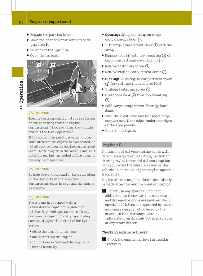
X Engage the parking brake.
X Move the gear selector lever to park
position P.
X Switch off the ignition.
X Open the tailgate.
G WARNING
Exercise extreme caution if you see flames
or smoke coming from the engine
compartment. Move away from the vehicle
and call the fire department.
If the coolant temperature warning lamp
indicates that the engine is overheated, do
not attempt to open the engine compartment
cover. Move away from the vehicle and wait
until the engine has cooled before opening
the engine compartment.
G WARNING
To help prevent personal injury, stay clear
of moving parts when the engine
compartment cover is open and the engine
is running.
G WARNING
The engine is equipped with a
transistorized ignition system that
utilizes high voltage. Do not touch any
components (ignition coils, spark plug
sockets, diagnostic socket) of the ignition
system
Rwhile the engine is running
Rwhile starting the engine
Rif ignition is “on” and the engine is
turned manually
X Opening: Grasp the strap on cargo
compartment floor;.
X Lift cargo compartment floor; with the
strap.
X Engage hook? into top mounting= of
cargo compartment cover blindA.
X Remove fastening screw:.
X Remove engine compartment coverA.
X Closing: Slide engine compartment cover
A forward into the tabs provided.
X Tighten fastening screw:.
X Disengage hook? from top mounting
=.
X Fold cargo compartment floor; back
down.
X Push the right hand and left hand cargo
compartment floor edges under the edges
of the side panels.
X Close the tailgate.
Engine oil
The amount of oil your engine needs will
depend on a number of factors, including
driving style. Increased oil consumption
can occur when the vehicle is new or the
vehicle is driven at higher engine speeds
frequently.
Engine oil consumption checks should only
be made after the vehicle break-in period.
! Do not use any special lubricantadditives, as these may increase wear
and damage the drive assemblies. Using
special additives not approved by smart
may cause damage not covered by the
smart Limited Warranty. More
information on this subject is available
at any smart center.
Checking engine oil level
! Check the engine oil level at regularintervals.
118 Engine compartment>>Operation.

When checking the engine oil level
Rthe vehicle must be parked on level
ground
Rthe vehicle must have been stationary for
at least five minutes with the engine
turned off
X Turn off the engine.
X Engage the parking brake.
X Open the tailgate.
X Open the engine compartment cover
(Y page 117).
The oil dipstick is located in the engine
compartment on the passenger side.
X Pull out oil dipstick:.
X Wipe oil dipstick: clean with a clean
cloth.
X Fully insert oil dipstick: into the
dipstick guide tube.
X Pull out oil dipstick: again after
approximately one minute to obtain
accurate reading.
The oil level is correct when it is
between lower mark= (minimum) and
upper mark; (maximum) on both sides
of oil dipstick:.
X Fully insert oil dipstick: into the
dipstick guide tube again.
X If necessary, add engine oil
(Y page 119).
i The filling quantity between the upperand lower marks on the oil dipstick is
approximately 1.1 US qt (1.0 l).
Adding engine oil
! Only use approved engine oils and oilfilters required for vehicles with
Maintenance System. For a listing of
approved engine oils and oil filters
contact an authorized smart center.
Using engine oils and oil filters of
specification other than those expressly
required for the Maintenance System, or
changing of oil and oil filter at change
intervals longer than those called for by
the Maintenance System will result in
engine or emission control system
damage not covered by the smart Limited
Warranty.
G WARNING
When adding engine oil, always use a funnel
to avoid spilling oil on any hot parts such
as the catalytic converter or exhaust
system.
If this should happen, however, the engine
must be thoroughly cleaned before you
continue your trip. The engine oil could
otherwise ignite.
The filler cap is located in the engine
compartment on the passenger side.
X Unscrew filler cap: from the filler
neck.
X Add engine oil as required.
Do not add more than 0.53 US qt (0.5 l)
engine oil at a time.
X Wait one minute until the engine oil has
run into the oil pan.
Engine compartment 119
>>Operation.
Z

X Check the engine oil level once more.
X Add engine oil once more if necessary.
Be careful not to spill any oil when adding
to avoid environmental damage caused by
oil entering the ground and water.
! Excess engine oil must be siphoned ordrained off. It could cause damage to the
engine or emission control system not
covered by the smart Limited Warranty.
X Screw filler cap: back on the filler
neck.
X Close the engine compartment cover
(Y page 117).
Front compartment
Service flap
Remove the service flap to check the
coolant level, windshield washer reservoir
level, and brake fluid level.
Insert the service flap on the front of the
vehicle so that it does not get damaged or
dirty.
i The service flap has a strap on the rearside that ties it to the vehicle body.
G WARNING
Always turn the key to starter switch
position 0 and remove the key from the
starter switch before opening the service
flap.
If the windshield wipers should
inadvertently be switched on, you could be
seriously injured by the wiper washer
drive, which is located just below the
service flap.
G WARNING
Make sure the service flap is locked while
driving. Otherwise, the service flap could
become detached and pose a hazard to you
or others.
G WARNING
To help prevent personal injury, stay clear
of moving parts when the service flap is
open.
The radiator fan may continue to run for
approximately 30 seconds or may even
restart after the engine has been turned
off. Stay clear of fan blades.
! Check the fill levels at regularintervals.
! Carefully remove ice, snow, and anyother deposits from the air intake
grilles above the service flap to ensure
air intake at all times.
X Park the vehicle on level ground.
X Turn off the engine.
X Engage the parking brake.
Removing
X Using a suitable object, push both
openers: towards the inside in
direction of the arrows.
Both levers; are released from the
radiator grille.
X Pull both levers; forward in direction
of the arrows.
120 Front compartment>>Operation.
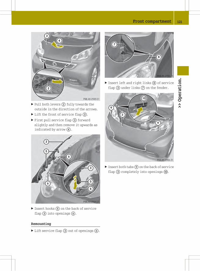
X Pull both levers; fully towards the
outside in the direction of the arrows.
X Lift the front of service flap=.
X First pull service flap= forward
slightly and then remove it upwards as
indicated by arrow?.
X Insert hooksA on the back of service
flap= into openingsB.
Remounting
X Lift service flap= out of openingsB.
X Insert left and right linksD of service
flap= under linksC on the fender.
X Insert both tabsE on the back of service
flap= completely into openingsF.
Front compartment 121
>>Operation.
Z

X Push service flap= down in direction
of arrowG.
X First push both levers; inward and then
to the rear.
X Press both levers; into the radiator
grille until they engage.
Coolant
G WARNING
In order to avoid potentially serious burns:
RUse extreme caution when opening the
service flap if there are any signs of
steam or coolant leaking from the
cooling system, or if the coolant
temperature warning lamp? in the
instrument cluster indicates that the
coolant is overheated.
RDo not remove the pressure cap on coolant
reservoir if coolant temperature is
above 158¦ (70¥). Allow engine to cool
down before removing cap. The coolant
reservoir contains hot fluid and is under
pressure.
RUsing a rag, slowly turn the cap
approximately 1/2 turn to relieve excess
pressure. If opened immediately,
scalding hot fluid and steam will be
blown out under pressure.
The engine coolant is a mixture of water
and anticorrosion/antifreeze. To check the
coolant level the vehicle must be parked on
level ground and the engine must have
cooled down. For more information, see
“Coolants” (Y page 223).
Checking coolant level
X Remove the service flap and insert it on
the front of the vehicle (Y page 120).
The coolant reservoir is located in the
front compartment on the driver’s side.
X Allow the radiator to cool down for at
least 30 minutes.
X Using a rag, slowly turn pressure
cap: approximately 1/2 turn
122 Front compartment>>Operation.
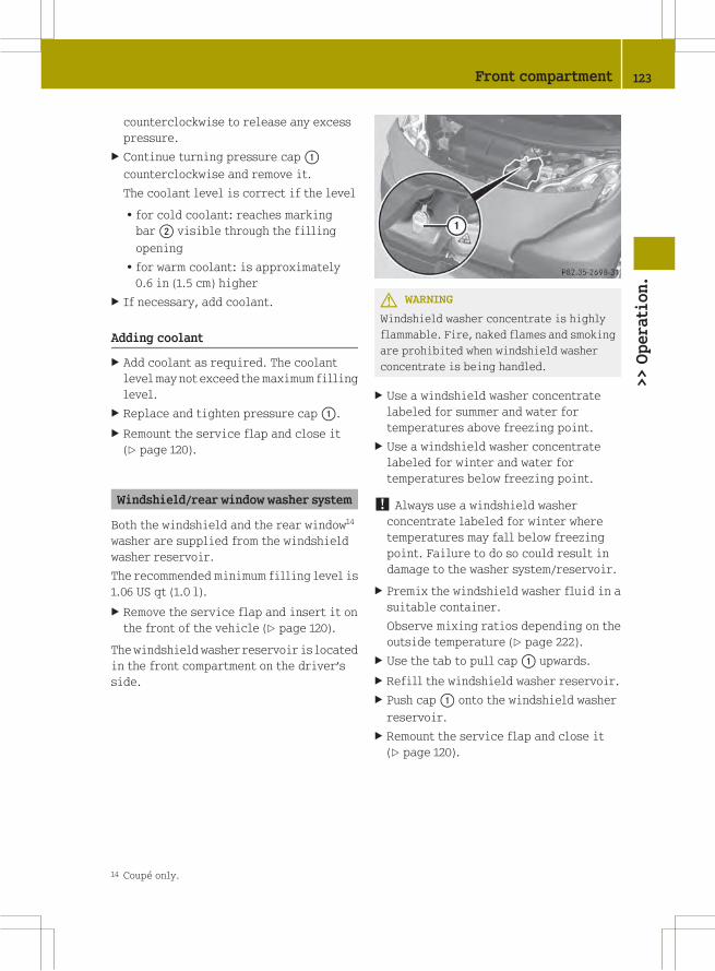
counterclockwise to release any excess
pressure.
X Continue turning pressure cap:
counterclockwise and remove it.
The coolant level is correct if the level
Rfor cold coolant: reaches marking
bar; visible through the filling
opening
Rfor warm coolant: is approximately
0.6 in (1.5 cm) higher
X If necessary, add coolant.
Adding coolant
X Add coolant as required. The coolant
levelmay not exceed themaximum filling
level.
X Replace and tighten pressure cap:.
X Remount the service flap and close it
(Y page 120).
Windshield/rear window washer system
Both the windshield and the rear window14
washer are supplied from the windshield
washer reservoir.
The recommended minimum filling level is
1.06 US qt (1.0 l).
X Remove the service flap and insert it on
the front of the vehicle (Y page 120).
The windshield washer reservoir is located
in the front compartment on the driver’s
side.
G WARNING
Windshield washer concentrate is highly
flammable. Fire, naked flames and smoking
are prohibited when windshield washer
concentrate is being handled.
X Use a windshield washer concentrate
labeled for summer and water for
temperatures above freezing point.
X Use a windshield washer concentrate
labeled for winter and water for
temperatures below freezing point.
! Always use a windshield washerconcentrate labeled for winter where
temperatures may fall below freezing
point. Failure to do so could result in
damage to the washer system/reservoir.
X Premix the windshield washer fluid in a
suitable container.
Observe mixing ratios depending on the
outside temperature (Y page 222).
X Use the tab to pull cap: upwards.
X Refill the windshield washer reservoir.
X Push cap: onto the windshield washer
reservoir.
X Remount the service flap and close it
(Y page 120).
14 Coupé only.
Front compartment 123
>>Operation.
Z

Brake fluid
G WARNING
During vehicle operation, the boiling
point of the brake fluid is continuously
reduced through the absorption of moisture
from the atmosphere. Under extremely
strenuous operating conditions, this
moisture content can lead to the formation
of bubbles in the system, thus reducing the
system’s efficiency.
Therefore, the brake fluid must be replaced
regularly. Refer to your vehicle’s
Maintenance Booklet for replacement
interval.
The brake fluid level in the brake fluid
reservoir may be too low if the brake
warning lamp in the instrument cluster
comes on (Y page 21) although the parking
brake is released.
! If you find that the brake fluid in thebrake fluid reservoir has fallen to the
minimum mark or below, have the brake
system checked for brake pad thickness
and leaks immediately. Contact an
authorized smart center immediately. Do
not add brake fluid as this will not solve
the problem.
X Remove the service flap and insert it on
the front of the vehicle (Y page 120).
The brake fluid reservoir is located in the
front compartment on the passenger side.
Checking brake fluid level
X Perform a visual check of the brake fluid
reservoir:.
The brake fluid level is correct when it
is between the minimum mark and the
maximum mark.
RIf the brake fluid level has fallen
slightly below the minimum mark,
drive to an authorized smart center.
RIf the brake fluid level has fallen
significantly below the minimum
mark, call Roadside Assistance or an
authorized smart center.
X Remount the service flap and close it
(Y page 120).
Tires and wheels
Safety notes
Contact an authorized smart center for
information on tested and recommended
rims and tires for summer and winter
operation. They can also offer advice
concerning tire service and purchase.
G WARNING
Replace rims or tires with the same
designation, manufacturer and type as
shown on the original part. For further
information contact an authorized smart
center. If incorrectly sized rims and tires
are mounted, the wheel brakes or
suspension components can be damaged.
Also, the operating clearance of the wheels
and the tires may no longer be correct.
G WARNING
Worn, old tires can cause accidents. If the
tire tread is worn to minimum tread depth,
or if the tires have sustained damage,
replace them.
When replacing rims, only use genuine
smart wheel bolts specified for the
particular rim type. Failure to do so can
124 Tires and wheels>>Operation.
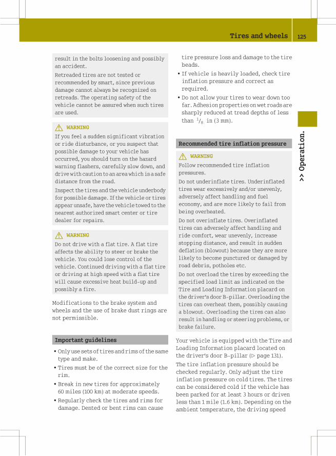
result in the bolts loosening and possibly
an accident.
Retreaded tires are not tested or
recommended by smart, since previous
damage cannot always be recognized on
retreads. The operating safety of the
vehicle cannot be assured when such tires
are used.
G WARNING
If you feel a sudden significant vibration
or ride disturbance, or you suspect that
possible damage to your vehicle has
occurred, you should turn on the hazard
warning flashers, carefully slow down, and
drive with caution to an area which is a safe
distance from the road.
Inspect the tires and the vehicle underbody
for possible damage. If the vehicle or tires
appear unsafe, have the vehicle towed to the
nearest authorized smart center or tire
dealer for repairs.
G WARNING
Do not drive with a flat tire. A flat tire
affects the ability to steer or brake the
vehicle. You could lose control of the
vehicle. Continued driving with a flat tire
or driving at high speed with a flat tire
will cause excessive heat build-up and
possibly a fire.
Modifications to the brake system and
wheels and the use of brake dust rings are
not permissible.
Important guidelines
ROnly use sets of tires and rims of the same
type and make.
RTires must be of the correct size for the
rim.
RBreak in new tires for approximately
60 miles (100 km) at moderate speeds.
RRegularly check the tires and rims for
damage. Dented or bent rims can cause
tire pressure loss and damage to the tire
beads.
RIf vehicle is heavily loaded, check tire
inflation pressure and correct as
required.
RDo not allow your tires to wear down too
far. Adhesion properties onwet roads are
sharply reduced at tread depths of less
than 1/8 in (3 mm).
Recommended tire inflation pressure
G WARNING
Follow recommended tire inflation
pressures.
Do not underinflate tires. Underinflated
tires wear excessively and/or unevenly,
adversely affect handling and fuel
economy, and are more likely to fail from
being overheated.
Do not overinflate tires. Overinflated
tires can adversely affect handling and
ride comfort, wear unevenly, increase
stopping distance, and result in sudden
deflation (blowout) because they are more
likely to become punctured or damaged by
road debris, potholes etc.
Do not overload the tires by exceeding the
specified load limit as indicated on the
Tire and Loading Information placard on
the driver’s door B‑pillar. Overloading the
tires can overheat them, possibly causing
a blowout. Overloading the tires can also
result in handling or steering problems, or
brake failure.
Your vehicle is equipped with the Tire and
Loading Information placard located on
the driver’s door B‑pillar (Y page 131).
The tire inflation pressure should be
checked regularly. Only adjust the tire
inflation pressure on cold tires. The tires
can be considered cold if the vehicle has
been parked for at least 3 hours or driven
less than 1 mile (1.6 km). Depending on the
ambient temperature, the driving speed
Tires and wheels 125
>>Operation.
Z

and the tire load, the tire temperature
changes. When the tire temperature
changes by 18¦ (10¥), the tire inflation
pressure will change by approximately
10 kpa (0.1 bar, 1.5 psi). Keep this in mind
when checking tire inflation pressure on
warm tires and adjust the tire pressure
only if the tire inflation pressure is too
low for the current operating conditions.
If you check the tire inflation pressure
when the tires are warm, the reading will
be higher than the cold reading. This is
normal. Do not let air out to match the
specified cold tire inflation pressure.
Otherwise, the tire will be underinflated.
Follow recommended cold tire inflation
pressures listed on Tire and Loading
Information placard on the driver’s door
B‑pillar.
Keeping the tires properly inflated
provides the best handling, tread life and
riding comfort.
In addition to the Tire and Loading
Information placard on the driver’s door
B‑pillar, also consult the tire inflation
pressure label (if available) on the inside
of the filler flap for any additional
information pertaining to special driving
situations. For more information, see
“Important notes on tire inflation
pressure” (Y page 126).
i Data shown on Tire and LoadingInformation placard example are for
illustration purposes only. Tire data are
specific to each vehicle and may vary
from data shown in the following
illustration. Refer to Tire and Loading
Information placard on vehicle for
actual data specific to your vehicle.
The Tire and Loading Information placard
lists the recommended cold tire inflation
pressures: for maximum loaded vehicle
weight. The tire inflation pressures listed
apply to the tires installed as original
equipment.
Important notes on tire inflation
pressure
G WARNING
If the tire inflation pressure drops
repeatedly, check the tires for punctures
from foreign objects and/or whether air is
leaking from the valves or from around the
rim.
Tire temperature and tire inflation
pressure are also increased while driving,
depending on the driving speed and the
tire load.
Potential problems associated with
underinflated and overinflated tires
Underinflated tires
G WARNING
Follow recommended tire inflation
pressures.
Do not underinflate tires. Underinflated
tires wear excessively and/or unevenly,
adversely affect handling and fuel
economy, and are more likely to fail from
being overheated.
126 Tires and wheels>>Operation.

Underinflated tires can
Rcause excessive and uneven tire wear
Radversely affect fuel economy
Rlead to tire failure from being
overheated
Radversely affect handling
characteristics
Overinflated tires
G WARNING
Follow recommended tire inflation
pressures.
Do not overinflate tires. Overinflated
tires can adversely affect handling and
ride comfort, wear unevenly, increase
stopping distance, and result in sudden
deflation (blowout) because they are more
likely to become punctured or damaged by
road debris, potholes etc.
Overinflated tires can
Radversely affect handling
characteristics
Rcause uneven tire wear
Rbe more prone to damage from road
hazards
Radversely affect ride comfort
Rincrease stopping distance
Checking tire inflation pressure
Safety notes
G WARNING
Follow recommended tire inflation
pressures.
Do not underinflate tires. Underinflated
tires wear excessively and/or unevenly,
adversely affect handling and fuel
economy, and are more likely to fail from
being overheated.
Do not overinflate tires. Overinflated
tires can adversely affect handling and
ride comfort, wear unevenly, increase
stopping distance, and result in sudden
deflation (blowout) because they are more
likely to become punctured or damaged by
road debris, potholes etc.
Do not overload the tires by exceeding the
specified load limit as indicated on the
Tire and Loading Information placard on
the driver’s door B‑pillar. Overloading the
tires can overheat them, possibly causing
a blowout. Overloading the tires can also
result in handling or steering problems, or
brake failure.
Check the tire inflation pressure at least
once a month.
Check and adjust the tire inflation
pressure when the tires are cold
(Y page 125).
Checking tire inflation pressure
manually
Follow the steps below to achieve correct
tire inflation pressure:
X Remove the cap from the valve on one tire.
X Firmly press a tire gauge onto the valve.
X Read the tire inflation pressure on tire
gauge and check against the
recommended tire inflation pressure on
the Tire and Loading Information
placard on the driver’s door B‑pillar
(Y page 131). If necessary, add air to
achieve the recommended tire inflation
pressure.
X If you have overfilled the tire, release
tire inflation pressure by pushing the
metal stem of the valve with e.g. a tip of
a pen. Then recheck the tire inflation
pressure with the tire gauge.
X Install the valve cap.
X Repeat this procedure for each tire.
Tires and wheels 127
>>Operation.
Z

Tire Pressure Monitoring System
(TPMS)*
Your vehicle may be equipped with a Tire
Pressure Monitoring System (TPMS).
It monitors the tire inflation pressure in
all four tires. A warning is issued to alert
you to a decrease in pressure in one or more
of the tires.
The Tire Pressure Monitoring System
(TPMS) is equipped with a combination low
tire pressure/TPMSmalfunction telltale in
the instrument cluster. Depending on how
the telltale illuminates, it indicates a low
tire pressure condition or amalfunction in
the TPMS system itself:
RIf the telltale illuminates continuously,
one ormore of your tires is significantly
underinflated. There is no malfunction
in the TPMS.
RIf the telltale flashes for 60 seconds and
then stays illuminated, the TPMS system
itself is not operating properly.
The TPMS only functions on wheels that are
equipped with the proper electronic
sensors.
G WARNING
The TPMS does not indicate a warning for
wrongly selected inflation pressures.
Always adjust tire inflation pressure
according to the Tire and Loading
Information placard on the driver’s door
B‑pillar.
The TPMS is not able to issue a warning due
to a sudden dramatic loss of pressure (e.g.
tire blowout caused by a foreign object). In
this case bring the vehicle to a halt by
carefully applying the brakes and avoiding
abrupt steering maneuvers.
G WARNING
Each tire should be checked monthly when
cold and inflated to the inflation pressure
recommended by the vehicle manufacturer
on the Tire and Loading Information
placard. If your vehicle has tires of a
different size than the size indicated on
the Tire and Loading Information placard,
you should determine the proper tire
inflation pressure for those tires.
As an added safety feature, your vehicle has
been equipped with a tire pressure
monitoring system (TPMS) that illuminates
a low tire pressure telltale when one or
more of your tires is significantly
underinflated.
Accordingly, when the low tire pressure
telltale illuminates, you should stop and
check your tires as soon as possible, and
inflate them to the proper pressure.
Driving on a significantly underinflated
tire causes the tire to overheat and can lead
to tire failure.
Underinflation also reduces fuel
efficiency and tire tread life, and may
affect the vehicle’s handling and stopping
ability. Please note that the TPMS is not a
substitute for proper tire maintenance,
and it is the driver’s responsibility to
maintain correct tire pressure, even if
underinflation has not reached the level to
trigger illumination of the TPMS low tire
pressure telltale.
Your vehicle has also been equipped with a
TPMS malfunction indicator to indicate
when the system is not operating properly.
The TPMS malfunction indicator is
combined with the low tire pressure
telltale. When the system detects a
malfunction, the telltale will flash for
approximately 1 minute and then remain
continuously illuminated.
This sequence will continue upon
subsequent vehicle start-ups as long as the
malfunction exists. When the malfunction
indicator is illuminated, the system may
not be able to detect or signal low tire
pressure as intended.
TPMS malfunctions may occur for a variety
of reasons, including the installation of
incompatible replacement or alternate
tires or wheels on the vehicle that prevent
128 Tires and wheels>>Operation.
* optional

the TPMS from functioning properly. Always
check the TPMS malfunction telltale after
replacing one or more tires or wheels on
your vehicle to ensure that the replacement
or alternate tires and wheels allow the
TPMS to continue to function properly.
i If a condition causing the TPMS tomalfunction develops, it may take up to
10 minutes for the system to signal a
malfunction using the TPMS telltale
flashing and illumination sequence.
The telltale extinguishes after a few
minutes driving if the malfunction has
been corrected.
i Operating radio transmissionequipment (e.g. wireless headsets, two-
way radios) in or near the vehicle could
cause the TPMS to malfunction.
i USA only:
This device complies with Part 15 of the
FCC Rules. Operation is subject to the
following two conditions:
RThis device may not cause harmful
interference, and
Rthis device must accept any
interference received, including
interference that may cause undesired
operation.
Any unauthorized modification to this
device could void the user’s authority to
operate the equipment.
i Canada only:
This device complies with RSS‑210 of
Industry Canada. Operation is subject to
the following two conditions:
RThis device may not cause
interference, and
Rthis device must accept any
interference received, including
interference that may cause undesired
operation of the device.
Any unauthorized modification to this
device could void the user’s authority to
operate the equipment.
Restarting the TPMS
G WARNING
It is the driver’s responsibility to
calibrate the TPMS on the recommended
cold inflation pressure. Underinflated
tires affect the ability to steer or brake
and might cause you to lose control of the
vehicle.
When you restart the TPMS, the system sets
new reference values for each tire.
The TPMS must be restarted when you have
adjusted the tire inflation pressure to a
new level (e.g. because of different load or
driving conditions). The TPMS is then
recalibrated to the current tire inflation
pressures.
X Using the Tire and Loading Information
placard on the driver’s door B‑pillar
(Y page 131), make sure the tire
inflation pressure of all four tires is
correct.
i Restart the TPMS after adjusting thetire inflation pressure to the inflation
pressure recommended for the vehicle
operating condition. Tire pressure
should only be adjusted on cold tires.
Observe the recommended tire inflation
pressure on the Tire and Loading
Information placard on the driver’s door
B‑pillar (Y page 131).
Tires and wheels 129
>>Operation.
Z

X Press Restarting TPMS button:.
The combination low tire pressure/TPMS
malfunction telltale in the instrument
cluster (Y page 21) flashes for
approximately 5 seconds and then goes
out.
After driving a few minutes the system
verifies that the current tire inflation
pressures are within the system’s
specified range. Afterwards the current
tire inflation pressures are accepted as
reference pressures and then monitored.
Maximum tire inflation pressure
G WARNING
Never exceed the max. tire inflation
pressure. Follow recommended tire
inflation pressures.
Do not underinflate tires. Underinflated
tires wear excessively and/or unevenly,
adversely affect handling and fuel
economy, and are more likely to fail from
being overheated.
Do not overinflate tires. Overinflated
tires can adversely affect handling and
ride comfort, wear unevenly, increase
stopping distance, and result in sudden
deflation (blowout) because they are more
likely to become punctured or damaged by
road debris, potholes etc.
i For illustration purposes only. Actualdata on tires are specific to each vehicle
and may vary from data shown in above
illustration.
This is the maximum permissible tire
inflation pressure: for the tire.
Always follow the recommended tire
inflation pressure (Y page 125) for proper
tire inflation.
Loading the vehicle
Two labels on your vehicle show how much
weight it may properly carry.
1) The Tire and Loading Information
placard can be found on the driver’s
door B‑pillar. This placard tells you
important information about the
number of people that can be in the
vehicle and the total weight that can be
carried in the vehicle. It also contains
information on the proper size and
recommended tire inflation pressures
for the original equipment tires on
your vehicle.
2) The certification label, also found on
the driver’s door B‑pillar, tells you
about the gross weight capacity of your
vehicle, called the Gross Vehicle
Weight Rating (GVWR). The GVWR
includes the weight of the vehicle, all
occupants, fuel and cargo. The
certification label also tells you about
the front and rear axle weight capacity,
called the Gross Axle Weight Rating
(GAWR). The GAWR is the total allowable
weight that can be carried by a single
axle (front or rear). Never exceed the
GVWR or GAWR for either the front axle
or rear axle.
130 Tires and wheels>>Operation.

: Driver’s door B‑pillar
Following is a discussion on how to work
with the information contained on the Tire
and Loading Information placard with
regards to loading your vehicle.
Tire and Loading Information
G WARNING
Do not overload the tires by exceeding the
specified load limit as indicated on the
Tire and Loading Information placard on
the driver’s door B‑pillar. Overloading the
tires can overheat them, possibly causing
a blowout. Overloading the tires can also
result in handling or steering problems, or
brake failure.
Tire and Loading Information placard
i Data shown on Tire and LoadingInformation placard example are for
illustration purposes only. Load limit
data are specific to each vehicle and may
vary from data shown in the following
illustration. Refer to Tire and Loading
Information placard on vehicle for
actual data specific to your vehicle.
The Tire and Loading Information placard
showing load limit information: is
located on the driver’s door B‑pillar
(Y page 131).
X Locate the statement “The combined
weight of occupants and cargo should
never exceed XXXX kg or XXXX lbs.” on the
Tire and Loading Information placard.
The combined weight of all occupants and
cargo/luggage should never exceed the
weight referenced in that statement.
Seating capacity
The seating capacity gives you important
information on the number of occupants
that can be in the vehicle. The Tire and
Loading Information placard showing
seating capacity: is located on the
driver’s door B‑pillar (Y page 131).
i Data shown on Tire and LoadingInformation placard example are for
illustration purposes only. Seating
capacity data are specific to each
vehicle and may vary from data shown in
Tires and wheels 131
>>Operation.
Z
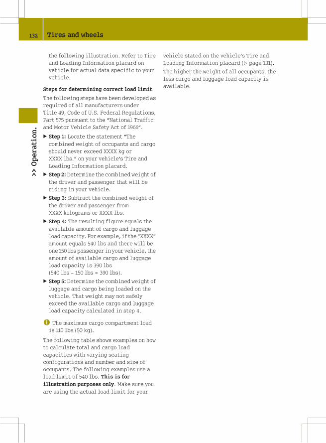
the following illustration. Refer to Tire
and Loading Information placard on
vehicle for actual data specific to your
vehicle.
Steps for determining correct load limit
The following steps have been developed as
required of all manufacturers under
Title 49, Code of U.S. Federal Regulations,
Part 575 pursuant to the “National Traffic
and Motor Vehicle Safety Act of 1966”.
X Step 1: Locate the statement “The
combined weight of occupants and cargo
should never exceed XXXX kg or
XXXX lbs.” on your vehicle’s Tire and
Loading Information placard.
X Step 2: Determine the combined weight of
the driver and passenger that will be
riding in your vehicle.
X Step 3: Subtract the combined weight of
the driver and passenger from
XXXX kilograms or XXXX lbs.
X Step 4: The resulting figure equals the
available amount of cargo and luggage
load capacity. For example, if the “XXXX”
amount equals 540 lbs and there will be
one 150 lbs passenger in your vehicle, the
amount of available cargo and luggage
load capacity is 390 lbs
(540 lbs - 150 lbs = 390 lbs).
X Step 5: Determine the combined weight of
luggage and cargo being loaded on the
vehicle. That weight may not safely
exceed the available cargo and luggage
load capacity calculated in step 4.
i The maximum cargo compartment loadis 110 lbs (50 kg).
The following table shows examples on how
to calculate total and cargo load
capacities with varying seating
configurations and number and size of
occupants. The following examples use a
load limit of 540 lbs. This is for
illustration purposes only. Make sure you
are using the actual load limit for your
vehicle stated on the vehicle’s Tire and
Loading Information placard (Y page 131).
The higher the weight of all occupants, the
less cargo and luggage load capacity is
available.
132 Tires and wheels>>Operation.

Examples for steps 1 to 3
Example 1 Example 2
Step 1 Combined weight limit of
occupants and cargo from Tire and
Loading Information placard
540 lbs 540 lbs
Step 2 Number of occupants (driver and
passenger)
2 1
Occupants weight Occupant 1: 150 lbs
Occupant 2: 180 lbs
Occupant 1: 150 lbs
Combined weight of all occupants 330 lbs 150 lbs
Step 3 Available cargo weight (total load
limit from Tire and Loading
Information placard minus
combined weight of all occupants)
540 lbs - 330 lbs =
210 lbs
540 lbs - 150 lbs =
390 lbs
Certification label
Even after careful determination of the
combined weight of all occupants and cargo
as to not exceed the permissible load
limit, you must make sure your vehicle
never exceeds the Gross Vehicle Weight
Rating (GVWR) and the Gross Axle Weight
Rating (GAWR) for either the front or rear
axle. You can obtain the GVWR and GAWR
from the certification label. The
certification label can be found on the
driver’s door B‑pillar, see “Technical
data” (Y page 214).
Gross Vehicle Weight Rating (GVWR) means:
The total weight of the vehicle, all
occupants, and all cargo must never exceed
the GVWR.
Gross Axle Weight Rating (GAWR) means:
The total allowable weight that can be
carried by a single axle (front or rear).
To assure that your vehicle does not exceed
the maximum permissible weight limits
(GVWR and GAWR for front and rear axle),
have the loaded vehicle (including driver,
passenger, and all cargo) weighed on a
suitable commercial scale.
Maximum tire load
G WARNING
Do not overload the tires by exceeding the
specified load limit as indicated on the
Tire and Loading Information placard on
the driver’s door B‑pillar. Overloading the
tires can overheat them, possibly causing
a blowout. Overloading the tires can also
result in handling or steering problems, or
brake failure.
i For illustration purposes only. Actualdata on tires are specific to each vehicle
and may vary from data shown in above
illustration.
The maximum tire load: is the maximum
weight the tires are designed to support.
Tires and wheels 133
>>Operation.
Z
For more information on tire load rating
(Y page 138).
For information on calculating total and
cargo load capacities (Y page 132).
Direction of rotation
Unidirectional tires offer added
advantages, such as better hydroplaning
performance. To benefit, however, you must
make sure the tires rotate in the direction
specified.
An arrow on the sidewall indicates the
intended direction of rotation (spinning)
of the tire.
Tire care and maintenance
G WARNING
Regularly check the tires for damage.
Damaged tires can cause tire inflation
pressure loss. As a result, you could lose
control of your vehicle.
Worn, old tires can cause accidents. If the
tire tread is badly worn, or if the tires have
sustained damage, replace them.
Check the tire inflation pressure at least
once a month. For more information on
checking tire inflation pressure, see
“Recommended tire inflation pressure”
(Y page 125).
Tire inspection
Every time you check the tire inflation
pressure, you should also inspect your
tires for the following
Rexcessive treadwear (Y page 134)
Rcord or fabric showing through the tire’s
rubber
Rbumps, bulges, cuts, cracks or splits in
the tread or side of the tire
Replace the tire if you find any of the above
conditions.
Life of tire
G WARNING
Tires should be replaced after 6 years,
regardless of the remaining tread.
The service life of a tire is dependent upon
varying factors including but not limited
to
Rdriving style
Rtire inflation pressure
Rdistance driven
Tread depth
G WARNING
Although the applicable federal motor
vehicle safety laws consider a tire to be
worn when the treadwear indicators (TWI)
become visible at approximately 1/16 in
(1.6 mm), we recommend that you do not allow
your tires to wear down to that level. As
tread depth approaches 1/8 in (3 mm), the
adhesion properties on a wet road are
sharply reduced.
Depending upon the weather and/or road
surface (conditions), the tire traction
varies widely.
Do not allow your tires to wear down too far.
Adhesion properties on wet roads are
sharply reduced at tread depths of less
than 1/8 in (3 mm).
Treadwear indicators (TWI) are required by
law. These indicators are located in six
places on the tread circumference and
become visible at a tread depth of
approximately 1/16 in (1.6 mm), at which
point the tire is considered worn and
should be replaced.
Recommended minimum tire tread depth:
Summer tires 1/8 in (3 mm)
Winter tires 1/6 in (4 mm)
134 Tires and wheels>>Operation.

Treadwear indicator: appears as a solid
band across the tread.
Storing tires
! Keep unmounted tires in a cool, dryplace with as little exposure to light as
possible. Protect tires from contact with
oil, grease and fuels.
Cleaning tires
! Never use a round nozzle to power washtires. The intense jet of water can result
in damage to the tire.
Always replace a damaged tire.
Uniform Tire Quality Grading
Standards
The Uniform Tire Quality Grading is a U.S.
Government requirement designed to give
drivers consistent and reliable
information regarding tire performance.
Tire manufacturers are required to grade
tires based on three performance factors:
treadwear:, traction;, and temperature
resistance=. Although not a Government
of Canada requirement, all tires made for
sale in North America have these grades
branded on the sidewall.
i For illustration purposes only. Actualdata on tires are specific to each vehicle
and may vary from data shown in above
illustration.
Quality grades can be found, where
applicable, on the tire sidewall between
tread shoulder and maximum section width.
For example:
Treadwear Traction Temperature
200 AA A
All passenger car tires must conform to
federal safety requirements in addition to
these grades.
Treadwear
The treadwear grade is a comparative
rating based on the wear rate of the tire
when tested under controlled conditions on
a specified U.S. government test course.
For example, a tire graded 150 would wear
one and one-half (1 1/2 ) times as well on the
government course as a tire graded 100.
The relative performance of tires depends
upon the actual conditions of their use,
however, andmay depart significantly from
the norm due to variations in driving
habits, service practices and differences
in road characteristics and climate.
Traction
G WARNING
The traction grade assigned to this tire is
based on straight-ahead braking traction
tests, and does not include acceleration,
cornering, hydroplaning, or peak traction
characteristics.
Tires and wheels 135
>>Operation.
Z

The traction grades, from highest to
lowest, are AA, A, B, and C. Those grades
represent the tire’s ability to stop on wet
pavement as measured under controlled
conditions on specified government test
surfaces of asphalt and concrete. A tire
marked C may have poor traction
performance.
Temperature
G WARNING
The temperature grade for this tire is
established for a tire that is properly
inflated and not overloaded. Excessive
speed, underinflation, or excessive
loading, either separately or in
combination, can cause excessive heat
build-up and possible tire failure.
The temperature grades are A (the highest),
B, and C, representing the tire’s resistance
to the generation of heat and its ability to
dissipate heat when tested under
controlled conditions on a specified
indoor laboratory test wheel. Sustained
high temperature can cause the material of
the tire to degenerate and reduce tire life,
and excessive temperature can lead to
sudden tire failure. The grade C
corresponds to a level of performance
which all passenger car tires must meet
under the Federal Motor Vehicle Safety
Standard No. 109. Grades B and A represent
higher levels of performance on the
laboratory test wheel than the minimum
required by law.
Rotating tires
G WARNING
Do not rotate front and rear wheels as they
have different dimensions, e.g. rim size,
wheel offset etc. Otherwise, the handling
can be affected and you could endanger
yourself and others.
Thoroughly clean the mounting face of the
wheels and brake discs, i.e. the inner side
of the wheels/tires each time the wheels/
tires are changed. Check for and ensure
proper tire inflation pressure.
G WARNING
Have the tightening torque checked after
changing a wheel. Wheels could become
loose if not tightened with a torque of
81 lb‑ft (110 Nm).
Only use genuine smart wheel bolts
specified for your vehicle’s rims.
For information on wheel change, see “Flat
tire” (Y page 186).
Tire labeling
Besides tire name (sales designation) and
manufacturer name, a number of markings
can be found on a tire.
Following are some explanations for the
markings on your vehicle’s tires:
: Uniform Quality Grading Standards
(Y page 135)
; DOT, Tire Identification Number (TIN)
(Y page 139)
= Maximum tire load (Y page 133)
? Maximum tire inflation pressure
(Y page 130)
136 Tires and wheels>>Operation.
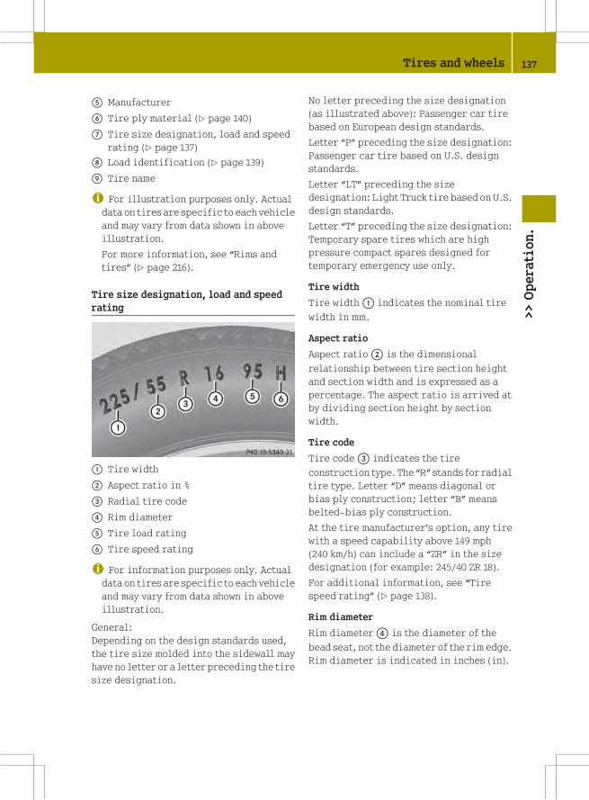
A Manufacturer
B Tire ply material (Y page 140)
C Tire size designation, load and speed
rating (Y page 137)
D Load identification (Y page 139)
E Tire name
i For illustration purposes only. Actualdata on tires are specific to each vehicle
and may vary from data shown in above
illustration.
For more information, see “Rims and
tires” (Y page 216).
Tire size designation, load and speed
rating
: Tire width
; Aspect ratio in %
= Radial tire code
? Rim diameter
A Tire load rating
B Tire speed rating
i For information purposes only. Actualdata on tires are specific to each vehicle
and may vary from data shown in above
illustration.
General:
Depending on the design standards used,
the tire size molded into the sidewall may
have no letter or a letter preceding the tire
size designation.
No letter preceding the size designation
(as illustrated above): Passenger car tire
based on European design standards.
Letter “P” preceding the size designation:
Passenger car tire based on U.S. design
standards.
Letter “LT” preceding the size
designation: Light Truck tire based on U.S.
design standards.
Letter “T” preceding the size designation:
Temporary spare tires which are high
pressure compact spares designed for
temporary emergency use only.
Tire width
Tire width: indicates the nominal tire
width in mm.
Aspect ratio
Aspect ratio; is the dimensional
relationship between tire section height
and section width and is expressed as a
percentage. The aspect ratio is arrived at
by dividing section height by section
width.
Tire code
Tire code= indicates the tire
construction type. The “R” stands for radial
tire type. Letter “D” means diagonal or
bias ply construction; letter “B” means
belted-bias ply construction.
At the tire manufacturer’s option, any tire
with a speed capability above 149 mph
(240 km/h) can include a “ZR” in the size
designation (for example: 245/40 ZR 18).
For additional information, see “Tire
speed rating” (Y page 138).
Rim diameter
Rim diameter? is the diameter of the
bead seat, not the diameter of the rim edge.
Rim diameter is indicated in inches (in).
Tires and wheels 137
>>Operation.
Z

Tire load rating
G WARNING
The tire load rating must always be at least
half of the GAWR of your vehicle. Otherwise,
tire failure may result and cause an
accident and/or serious personal injury to
you or others.
Always replace rims and tires with the same
designation, manufacturer and type as
shown on the original part.
G WARNING
Do not overload the tires by exceeding the
specified load limit as indicated on the
Tire and Loading Information placard on
the driver’s door B‑pillar. Overloading the
tires can overheat them, possibly causing
a blowout. Overloading the tires can also
result in handling or steering problems, or
brake failure.
Tire load ratingA is a numerical code
associated with the maximum load a tire
can support.
For example, a load rating of 91
corresponds to a maximum load of 1 356 lbs
(615 kg) the tire is designed to support.
See also “Maximum tire load” (Y page 133)
where the maximum load associated with
the load index is indicated in kilograms
and lbs.
For additional information on tire load
rating, see “Load identification”
(Y page 139).
Tire speed rating
G WARNING
Even when permitted by law, never operate
a vehicle at speeds greater than the
maximum speed rating of the tires.
Exceeding the maximum speed for which
tires are rated can lead to sudden tire
failure, causing loss of vehicle control and
possibly resulting in an accident and/or
personal injury and possible death, for you
and for others.
Regardless of the tire speed rating, local
speed limits should be obeyed. Use prudent
driving speeds appropriate to prevailing
conditions.
Tire speed ratingB indicates the
approved maximum speed for the tire.
Summer tires
Index Speed rating
Q up to 100 mph (160 km/h)
R up to 106 mph (170 km/h)
S up to 112 mph (180 km/h)
T up to 118 mph (190 km/h)
H up to 130 mph (210 km/h)
V up to 149 mph (240 km/h)
W up to 168 mph (270 km/h)
Y up to 186 mph (300 km/h)
ZR...Y above 186 mph (300 km/h)
ZR...(Y) above 186 mph (300 km/h)
ZR above 149 mph (240 km/h)
RAt the tire manufacturer’s option, any
tire with a speed capability above
149 mph (240 km/h) can include a “ZR” in
the size designation (for example:
245/40 ZR18). To determine the maximum
speed capability of the tire, the service
description for the tire must be referred
to.
The service description is comprised of
tire load ratingA and tire speed rating
B.
If your tire includes “ZR” in the size
designation and no service description
is given, the tire manufacturer must be
consulted for the maximum speed
capability.
If a service description is given, the
speed capability is limited by the speed
138 Tires and wheels>>Operation.
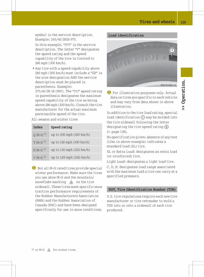
symbol in the service description.
Example: 245/40 ZR18 97Y.
In this example, “97Y” is the service
description. The letter “Y” designates
the speed rating and the speed
capability of the tire is limited to
186 mph (300 km/h).
RAny tire with a speed capability above
186 mph (300 km/h) must include a “ZR” in
the size designation AND the service
description must be placed in
parenthesis. Example:
275/40 ZR 18 (99Y). The “(Y)” speed rating
in parenthesis designates the maximum
speed capability of the tire as being
above 186 mph (300 km/h). Consult the tire
manufacturer for the actual maximum
permissible speed of the tire.
All-season and winter tires
Index Speed rating
Q M+S 15 up to 100 mph (160 km/h)
T M+S 15 up to 118 mph (190 km/h)
H M+S 15 up to 130 mph (210 km/h)
V M+S 15 up to 149 mph (240 km/h)
i Not all M+S rated tires provide specialwinter performance. Make sure the tires
you use show M+S and the mountain/
snowflake markingi on the tire
sidewall. These tires meet specific snow
traction performance requirements of
the Rubber Manufacturers Association
(RMA) and the Rubber Association of
Canada (RAC) and have been designed
specifically for use in snow conditions.
Load identification
i For illustration purposes only. Actualdata on tires are specific to each vehicle
and may vary from data shown in above
illustration.
In addition to the tire load rating, special
load identification: may be molded into
the tire sidewall following the letter
designating the tire speed ratingB
(Y page 138).
No specification given: absence of any text
(like in above example) indicates a
standard load (SL) tire.
XL or Extra Load: designates an extra load
(or reinforced) tire.
Light Load: designates a light load tire.
C, D, E: designates load range associated
with the maximum load a tire can carry at a
specified pressure.
DOT, Tire Identification Number (TIN)
U.S. tire regulations require each new tire
manufacturer or tire retreader to mold a
TIN into or onto a sidewall of each tire
produced.
15 or M+Si for winter tires.
Tires and wheels 139
>>Operation.
Z

The TIN is a unique identifier which
facilitates efforts by tire manufactures to
notify purchasers in recall situations or
other safety matters concerning tires and
gives purchasers the means to easily
identify such tires.
The TIN is comprised of “Manufacturer’s
identification mark”;, “Tire size”=,
“Tire type code”?, and “Date of
manufacture”A.
i For illustration purposes only. Actualdata on tires are specific to each vehicle
and may vary from data shown in above
illustration.
DOT (Department of Transportation)
Tire branding symbol: which denotes the
tire meets requirements of the U.S.
Department of Transportation.
Manufacturer’s identification mark
Manufacturer’s identification mark;
denotes the tire manufacturer.
New tires have a mark with two symbols.
Retreaded tires have a mark with four
symbols. For more information on
retreaded tires (Y page 124).
Tire size
Code= indicates the tire size.
Tire type code
Tire type code? may, at the option of the
manufacturer, be used as a descriptive
code for identifying significant
characteristics of the tire.
Date of manufacture
Date of manufactureA identifies the week
and year of manufacture.
The first two figures identify the week,
starting with “01” to represent the first
full week of the calendar year. The second
two figures represent the year.
For example, “3202” represents the 32nd
week of 2002.
Tire ply material
i For illustration purposes only. Actualdata on tires are specific to each vehicle
and may vary from data shown in above
illustration.
This marking tells you about the type of
cord and number of plies in the
sidewall: and under the tread;.
Tire and loading terminology
Accessory weight
The combined weight (in excess of those
standard items which may be replaced) of
automatic transmission, power steering,
power brakes, power windows, power seats,
140 Tires and wheels>>Operation.

radio, and heater, to the extent that these
items are available as factory-installed
equipment (whether installed or not).
Air pressure
The amount of air inside the tire pressing
outward on each square inch of the tire. Air
pressure is expressed in pounds per square
inch (psi), or kilopascal (kPa) or bars.
Aspect ratio
Dimensional relationship between tire
section height and section width expressed
in percentage.
Bar
Another metric unit for air pressure. There
are 14.5038 pounds per square inch (psi) to
1 bar; there are 100 kilopascals (kPa) to
1 bar.
Bead
The tire bead contains steel wires wrapped
by steel cords that hold the tire onto the
rim.
Cold tire inflation pressure
Tire inflation pressure when your vehicle
has been sitting for at least 3 hours or
driven no more than 1 mile (1.6 km).
Curb weight
The weight of a motor vehicle with standard
equipment including the maximum
capacity of fuel, oil, and coolant, and, if
so equipped, air conditioning and
additional optional equipment, but
without passengers and cargo.
DOT (Department of Transportation)
A tire branding symbol which denotes the
tire meets requirements of the U.S.
Department of Transportation.
GAWR (Gross Axle Weight Rating)
The GAWR is the maximum permissible axle
weight. The gross vehicle weight on each
axle must never exceed the GAWR for the
front and rear axle indicated on the
certification label located on the driver’s
door B‑pillar.
GVW (Gross Vehicle Weight)
The GVW comprises the weight of the
vehicle including fuel, tools, installed
accessories, passengers and cargo. The
GVW must never exceed the GVWR indicated
on the certification label located on the
driver’s door B‑pillar.
GVWR (Gross Vehicle Weight Rating)
This is the maximum permissible vehicle
weight of the fully loaded vehicle (weight
of the vehicle including all options,
passengers, fuel, and cargo. It is indicated
on certification label located on the
driver’s door B‑pillar.
Kilopascal (kPa)
The metric unit for air pressure. There are
6.9 kPa to 1 psi; another metric unit for air
pressure is bars. There are
100 kilopascals (kPa) to 1 bar.
Maximum load rating
The maximum load in kilograms and pounds
that can be carried by the tire.
Maximum loaded vehicle weight
The sum of curb weight, accessory weight,
total load limit and production options
weight.
Maximum permissible tire inflation
pressure
This number is the greatest amount of air
pressure that should ever be put in the tire.
Tires and wheels 141
>>Operation.
Z

Normal occupant weight
The number of occupants the vehicle is
designed to seat, multiplied by
68 kilograms (150 lbs).
Occupant distribution
The distribution of occupants in a vehicle
at their designated seating positions.
Production options weight
The combined weight of those installed
regular production options weighing over
5 lbs (2.3 kilograms) in excess of those
standard items which they replace, not
previously considered in curb weight or
accessory weight, including heavy duty
brakes, ride levelers, roof rack, heavy duty
battery, and special trim.
PSI (Pounds per square inch)
A standard unit of measure for air
pressure.
Recommended tire inflation pressure
The recommended tire inflation pressure
for normal driving conditions is listed on
the Tire and Loading Information placard
located on driver’s door B‑pillar and
provides best handling, tread life and
riding comfort.
Rim
A metal support for a tire or a tire and tube
assembly upon which the tire beads are
seated.
Sidewall
The portion of a tire between the tread and
the bead.
TIN (Tire Identification Number)
Unique identifier which facilitates
efforts by tire manufacturers to notify
purchasers in recall situations or other
safety matters concerning tires and gives
purchasers the means to easily identify
such tires. The TIN is comprised of
“Manufacturer’s identification mark”,
“Tire size”, “Tire type code” and “Date of
manufacture”.
Tire load rating
Numerical code associated with the
maximum load a tire can support.
Tire ply composition and material used
This indicates the number of plies or the
number of layers of rubber-coated fabric
in the tire tread and sidewall. Tire
manufacturers also must indicate the ply
materials in the tire and sidewall, which
include steel, nylon, polyester, and others.
Tire speed rating
Part of tire designation; indicates the
speed range for which a tire is approved.
Total load limit
Rated cargo and luggage load plus
68 kilograms (150 lbs) times the vehicle’s
designated seating capacity.
Traction
Force exerted by the vehicle on the road via
the tires. The amount of grip provided.
Tread
The portion of a tire that comes into
contact with the road.
142 Tires and wheels>>Operation.

Treadwear indicators
Narrow bands, sometimes called “wear
bars” that show across the tread of a tire
when only 1/16 in (1.6 mm) of tread remains.
Uniform Tire Quality Grading Standards
A tire information system that provides
consumers with ratings for a tire’s
traction, temperature and treadwear.
Ratings are determined by tire
manufacturers using U.S. government
testing procedures. The ratings aremolded
into the sidewall of the tire.
Vehicle maximum load on the tire
Load on an individual tire that is
determined by distributing to each axle
its share of the maximum loaded vehicle
weight and dividing it by two.
Winter driving
Before the onset of winter, have your
vehicle winterized at an authorized smart
center.
This service includes:
RCheck of anticorrosion and antifreeze
concentration.
RAddition of washer concentrate to the
water of the windshield/rear window.
Use a windshield washer concentrate
labeled for winter which is formulated
for temperatures below freezing point
(Y page 222).
RBattery test. Battery capacity drops with
decreasing ambient temperature. A well
charged battery helps to make sure the
engine can be started, even at low
ambient temperatures.
RTire change.
Winter tires
G WARNING
Winter tires with a tread depth of less
than 1/6 in (4 mm) must be replaced. They
are no longer suitable for winter
operation.
Always use winter tires at temperatures
below 45¦ (7¥) and whenever wintry road
conditions prevail. Not all M+S rated tires
provide special winter performance. Make
sure the tires you use show the mountain/
snowflake markingi on the tire
sidewall. These tires meet specific snow
traction performance requirements of the
Rubber Manufacturers Association (RMA)
and the Rubber Association of Canada (RAC)
and have been designed specifically for
use in snow conditions. Use of winter tires
is the only way to achieve the maximum
effectiveness of the ABS and ESP® in winter
operation.
For safe handling, make sure all mounted
winter tires are of the same make and have
the same tread design.
For information on winter tires for your
vehicle model, see the "Technical data"
section (Y page 216).
Always observe the speed rating of the
winter tires installed on your vehicle. If
the maximum speed for which your tires are
rated is below the speed rating of your
vehicle, you must place a notice to this
effect where it will be seen by the driver.
Such notices are available at your tire
dealer or any authorized smart center.
Snow chains*
! Remember that snow chains must alwaysbe compatible with the tire sizes of a
vehicle. Snow chains that are approved
by smart are only permitted for the
following tire size:
175/55 R15 on the rear axle.
Winter driving 143
>>Operation.
* optional Z

For safety reasons, smart recommends
that you only use snow chains that have
been approved by smart.
Information on this is available from any
smart center.
Please refer to the separate operating
instructions for detailed information on
mounting the snow chains.
Snow chains should only be driven on
snow-covered roads at speeds not to
exceed 30 mph (50 km/h). Remove chains
as soon as possible when driving on roads
without snow.
Please observe the following guidelines
when using snow chains:
RUsing snow chains is not permissible
with all wheel/tire combinations
(Y page 216).
RUse snow chains in pairs and on rear
wheels only. Follow the manufacturer’s
mounting instructions.
RUse of snow chains may be prohibited
depending on location. Always check
local and state laws before mounting
snow chains.
G WARNING
When mounting or removing snow chains,
always park your vehicle on level ground,
engage the parking brake, and turn off the
engine. The vehicle could otherwise move
and injure yourself or other road users.
G WARNING
When mounting and removing snow chains,
ensure that you and your vehicle are at a
safe distance from moving traffic. Not
doing so could endanger other road users or
even lead to you being injured by the
vehicles behind you.
G WARNING
The vehicle’s handling changes when
driving with snow chains on any kind of
road surface. This means that you should
always adapt your driving style to suit the
current road and weather conditions.
! If snow chains that do not meetrequirements are mounted, they may
scrape against the body or axle
components when the vehicle is in
motion. This could result in damage to
the rim/tire or vehicle.
Driving instructions
Drinking and driving
G WARNING
Do not drink alcohol or take drugs and drive
or allow anyone to drive who has been
drinking alcohol or taking drugs. Even a
small amount of alcohol or drugs can affect
your reflexes, perceptions and judgment.
The possibility of a serious or even fatal
accident are greatly increased when you
drink or take drugs and drive.
Pedals
G WARNING
Make sure absolutely no objects are
obstructing the pedals’ range of motion.
Keep the driver’s footwell clear of all
obstacles. If there are any floormats* or
carpets in the footwell, make sure the
pedals still have sufficient clearance.
During sudden acceleration or braking
maneuvers, the objects could get caught
between or beneath the pedals and restrict
your ability to brake or accelerate. This
could lead to accidents and/or injury.
Power assistance
G WARNING
With the engine not running, there is no
power assistance for the brake and
steering* systems. In this case, it is
144 Driving instructions>>Operation.
* optional

important to keep in mind that a
considerably higher degree of effort is
necessary to brake and steer the vehicle.
Adapt your driving accordingly.
Brakes
G WARNING
Make sure not to endanger any other road
users when carrying out braking
maneuvers.
Refer to the description of the hydraulic
brake assistant (Y page 48).
! Because the ESP® operatesautomatically, the engine must be turned
off (ignition switched off) when the
parking brake is being tested on a brake
test dynamometer. Active braking action
through the ESP®may otherwise seriously
damage the brake system which is not
covered by the smart Limited Warranty.
Brake pad wear or a leak in the brake system
may be the reason for low brake fluid level
in the brake fluid reservoir.
The brake fluid level in the brake fluid
reservoir may be too low if the brake
warning lamp in the instrument cluster
comes on (Y page 21) although the parking
brake is released.
Have the brake system inspected
immediately. Contact an authorized smart
center.
All checks and service work on the brake
system should be carried out by qualified
technicians only. Contact an authorized
smart center.
Only install brake pads and use brake fluid
recommended by smart.
Inclines
! When driving down long and steepgrades, relieve the load on the brakes by
shifting into a lower gear to use the
engine’s braking power. This helps
prevent overheating of the brakes and
reduces brake pad wear.
When using the engine’s braking power, a
drive wheel may not spin for an extended
period of time, e.g. on slippery road
surfaces. This may cause serious damage
to the drive- train which is not covered
by the smart Limited Warranty.
High and low stresses
G WARNING
Resting your foot on the brake pedal will
cause excessive and premature wear of the
brake pads.
It can also result in the brakes
overheating, thereby significantly
reducing their effectiveness and your
ability to stop the vehicle in sufficient
time to avoid an accident.
After hard braking, it is advisable to drive
on for some time, rather than immediately
park, so that the air stream will cool down
the brakes faster.
If your brake system is normally only
subjected to moderate loads, you should
occasionally test the effectiveness of the
brakes by applying above-normal braking
pressure at higher speeds. This will also
enhance the grip of the brake pads.
G WARNING
Make sure not to endanger any other road
users when carrying out these braking
maneuvers.
Wet road surface
G WARNING
After driving in heavy rain for some time
without applying the brakes or through
water deep enough to wet brake components,
the first braking action may be somewhat
reduced and increased pedal pressure may
be necessary to obtain expected braking
Driving instructions 145
>>Operation.
Z

effect. Maintain a safe distance from
vehicles in front.
To help prevent brake disc corrosion after
driving on wet road surfaces (particularly
salted roads), it is advisable to brake the
vehicle with considerable force prior to
parking. The heat generated serves to dry
the brakes.
G WARNING
Make sure not to endanger any other road
users when carrying out these braking
maneuvers.
Limited braking effect on salted roads
Remember that the effect of the brakes can
be limited on salted road surfaces. A layer
of salt can form on brake discs and brake
pads, considerably reducing the friction
between the brake disc and the brake pad.
The effect is most noticeable after long
trips without braking, e.g. on the highway,
and after the vehicle has been parked for
several hours.
G WARNING
The accumulation of salt on brake discs and
brake pads reduces braking effectiveness
and increases the distance necessary to
come to a complete standstill. This could
potentially cause an accident and/or
personal injury.
To avoid this risk, you should
Rbrake carefully every now and then on
salted roads in order to remove any layer
of salt on the brake disc and brake pad,
but do so without endangering any other
road users
Rkeep a good safe distance from the
vehicle in front and drive carefully
Rpress the brake carefully at the end of the
trip and again when beginning the next
trip in order to remove any salt residues
from the brake disc
New brake pads
Only install brake pads recommended by
smart.
G WARNING
If other than recommended brake pads are
installed, or other than recommended brake
fluid is used, the braking properties of the
vehicle can be degraded to an extent that
safe braking is substantially impaired.
This could result in an accident.
G WARNING
New brake pads will not achieve their
optimal braking effect until after several
hundred miles (kilometers). This means
that you must compensate for the reduced
braking effect by pressing harder on the
brake pedal and adapt your driving style
accordingly. The same applies after brake
pads or brake discs have been changed.
Drive sensibly - save fuel
Fuel consumption, to a great extent,
depends on driving habits and operating
conditions.
To save fuel you should:
RShift gears in a timely manner.
RAvoid frequent acceleration and
deceleration.
RKeep tires at the recommended inflation
pressures.
RRemove carriers* when not in use.
RRemove unnecessary loads.
RAllow engine to warm up under low load
use.
RHave all maintenance work performed at
the intervals specified in the
Maintenance Booklet and as required by
the Maintenance System. Contact an
authorized smart center.
Fuel consumption is also increased by
driving in cold weather, in stop-and-go
traffic, on short trips, and in hilly areas.
146 Driving instructions>>Operation.
* optional

Catalytic converter
Your smart is equipped with monolithic-
type catalytic converter, an important
element in conjunction with the oxygen
sensors to achieve substantial control of
the pollutants in the exhaust emissions.
Keep your vehicle in proper operating
condition by following our recommended
maintenance instructions as outlined in
your Maintenance Booklet.
G WARNING
The catalytic converter can become very
hot. Coming into contact with the catalytic
converter could result in burns.
Note the following:
RDo not remove the protective heat guards.
RDo not apply any underseal.
RAs with any vehicle, do not idle, park, or
operate this vehicle in areas where
combustible materials such as grass,
hay, or leaves can come into contact with
the hot exhaust system, as these
materials could be ignited and cause a
vehicle fire.
! To prevent damage to the catalyticconverter, only use premium unleaded
gasoline in this vehicle.
Any noticeable irregularities in engine
operation should be repaired promptly.
Otherwise, excessive unburned fuel may
reach the catalytic converter, causing it
to overheat and potentially start a fire.
It is essential to observe the following
points, as there is otherwise a danger of
overheating and the catalytic converter
may be damaged.
RFill up only with premium unleaded
gasoline. Even small quantities of
leaded gasoline can damage the catalytic
converter.
RMake sure you adhere to the prescribed
service intervals.
RNever run the fuel tank empty.
RIf the engine starts to misfire, bring the
vehicle to an immediate standstill
without endangering traffic.
RIf the engine fails to start the first time,
you should not try to start it any more
than three times in succession.
RDo not try to start for more than four
seconds at a time.
Tires
G WARNING
If you feel a sudden significant vibration
or ride disturbance, or you suspect that
possible damage to your vehicle has
occurred, you should turn on the hazard
warning flashers, carefully slow down, and
drive with caution to an area which is a safe
distance from the road.
Inspect the tires and the vehicle underbody
for possible damage. If the vehicle or tires
appear unsafe, have the vehicle towed to the
nearest smart center or tire dealer for
repairs.
Treadwear indicators (TWI) are required by
law. These indicators are located in six
places on the tread circumference and
become visible at a tread depth of
approximately 1/16 in (1.6 mm), at which
point the tire is considered worn and
should be replaced.
The treadwear indicator appears as a solid
band across the tread.
G WARNING
Although the applicable federal motor
vehicle safety laws consider a tire to be
worn when the treadwear indicators (TWI)
become visible at approximately 1/16 in
(1.6 mm), we recommend that you do not allow
your tires to wear down to that level. As
tread depth approaches 1/8 in (3 mm), the
adhesion properties on a wet road are
sharply reduced.
Driving instructions 147
>>Operation.
Z
Depending upon the weather and/or road
surface (conditions), the tire traction
varies widely.
Specified tire inflation pressures must be
maintained. This applies particularly if
the tires are subject to high loads (e.g.
high speeds, heavy loads, high ambient
temperatures).
G WARNING
Do not drive with a flat tire. A flat tire will
affect your ability to steer or brake andmay
cause you to lose control of the vehicle.
Continued driving with a flat tire or
driving at high speed with a flat tire will
cause excessive heat build-up and possibly
a fire.
For more information, see “Tires and
wheels” (Y page 124).
Hydroplaning
Depending on the depth of the water layer
on the road, hydroplaning may occur
resulting in a loss of control, even at low
speeds and with new tires. Reduce vehicle
speed, avoid track grooves in the road and
apply brakes cautiously when it is raining.
Tire traction
The safe speed on a wet, snow covered or icy
road is always lower than on a dry road.
You should pay particular attention to the
condition of the road whenever the outside
temperatures are close to the freezing
point.
G WARNING
If ice has formed on the road, tire traction
will be substantially reduced. Under such
weather conditions, drive, steer and brake
with extreme caution.
smart recommends winter tires
(Y page 143) with a minimum tread depth of
approximately 1/6 in (4 mm) on all four
wheels for the winter season to ensure
normal balanced handling characteristics.
On packed snow, they can reduce your
stopping distance compared to summer
tires.
Stopping distance, however, is still
considerably greater than when the road is
not covered with snow or ice. Exercise
appropriate caution.
! Avoid spinning of a drive wheel for anextended period when driving off on
slippery road surfaces. Otherwise, the
drivetrain could be damaged, which is
not covered by the smart Limited
Warranty.
Tire speed rating
Regardless of the tire speed rating, local
speed limits should be obeyed. Use prudent
driving speeds appropriate to prevailing
conditions.
G WARNING
Even when permitted by law, never operate
a vehicle at speeds greater than the
maximum speed rating of the tires.
Exceeding the maximum speed for which
tires are rated can lead to sudden tire
failure, causing loss of vehicle control and
possibly resulting in an accident and/or
personal injury and possible death, for you
and for others.
An electronic speed limiter prevents your
vehicle from exceeding a speed of 90 mph
(145 km/h).
The factory equipped tires on your vehicle
may have a tire speed rating above the
maximum speed permitted by the
electronic speed limiter.
Make sure your tires have the required tire
speed rating as specified for your vehicle
in the “Technical data section”
148 Driving instructions>>Operation.

(Y page 216), for example when purchasing
new tires.
For information on how to identify the tire
speed rating on a tire’s sidewall, see “Tire
size designation, load and speed rating”
(Y page 137).
If you are uncertain about the correct
reading of the information given on a
tire’s sidewall, any authorized smart
center will be glad to assist you.
i For information on speed ratings forwinter tires, see “All-season and winter
tires” (Y page 138).
Winter driving instructions
The most important rule for slippery or icy
roads is to drive sensibly and to avoid
abrupt acceleration, braking and steering
maneuvers.
When the vehicle is in danger of skidding,
move gear selector lever to neutral
position N. Try to keep the vehicle under
control by corrective steering action.
For information on driving with snow
chains*, see “Snow chains*” (Y page 143).
G WARNING
On slippery road surfaces, never downshift
in order to obtain braking action. This
could result in drive wheel slip and
reduced vehicle control. Your vehicle’s ABS
will not prevent this type of loss of control.
Road salts and chemicals can adversely
affect braking efficiency. Increased pedal
force may become necessary to produce the
normal braking effect.
Depressing the brake pedal periodically
when traveling at length on salt-strewn
roads can bring road-salt-impaired
braking efficiency back to normal.
If the vehicle is parked after being driven
on salt-treated roads, the braking
efficiency should be tested as soon as
possible after driving is resumed.
G WARNING
Make sure not to endanger any other road
users when carrying out these braking
maneuvers.
G WARNING
If the vehicle becomes stuck in snow, make
sure snow is kept clear of the exhaust pipe
and from around the vehicle with the engine
running. Otherwise, deadly carbon
monoxide (CO) gases may enter vehicle
interior resulting in unconsciousness and
death.
To assure sufficient fresh air ventilation,
open a window slightly on the side of the
vehicle not facing the wind.
G WARNING
The outside temperature display is not
designed to serve as an ice-warning device
and is therefore unsuitable for that
purpose. Indicated temperatures just
above the freezing point do not guarantee
that the road surface is free of ice.
Formore information, see “Winter driving”
(Y page 143).
Standing water
! Do not drive through flooded areas orwater of unknown depth. Before driving
through water, determine its depth.
Never accelerate before driving into
water. The bow wave could force water
into the engine and auxiliary
equipment, thus damaging them.
If you must drive through standing water,
drive slowly to prevent water from entering
Rthe front compartment
Rthe engine compartment
Rthe passenger compartment
Water in these areas could cause damage to
electrical components or wiring of the
engine or transmission, or could result in
Driving instructions 149
>>Operation.
* optional Z

water being ingested by the engine through
the air intake, causing severe internal
engine damage.
Any such damage is not covered by the smart
Limited Warranty.
Passenger compartment
G WARNING
Always fasten items being carried as
securely as possible.
In an accident, during hard braking or
sudden maneuvers, loose items thrown
around inside the vehicle may injure
vehicle occupants.
The cargo compartment is the preferred
place to carry objects.
Control and operation of radio
transmitters
Radio and telephone
G WARNING
Please do not forget that your primary
responsibility is to drive the vehicle
safely. Only operate the radio or
telephone 16 if road, weather and traffic
conditions permit.
Bear in mind that at a speed of just 30 mph
(approximately 50 km/h), your vehicle is
covering a distance of 44 feet
(approximately 14 m) every second.
Telephones and two-way radios
G WARNING
Never operate radio transmitters equipped
with a built-in or attached antenna (i.e.
without being connected to an external
antenna) from inside the vehicle while the
engine is running. Doing so could lead to a
malfunction of the vehicle’s electronic
system, possibly resulting in an accident
and/or serious personal injury.
Radio transmitters, such as a mobile phone
or a citizens band unit should only be used
inside the vehicle if they are connected to
an antenna that is installed on the outside
of the vehicle.
Refer to the radio transmitter operation
instructions regarding use of an external
antenna.
Emission control
Certain engine systems serve to keep the
toxic components of the exhaust gases
within permissible legal limits.
These systems, of course, will function
properly only when maintained strictly
according to factory specifications.
Any adjustments to the engine should
therefore be carried out only by qualified
smart center authorized technicians.
Engine adjustments should not be altered
in any way. Moreover, the specified service
jobs must be carried out regularly
according to smart servicing
requirements. For details refer to the
Maintenance Booklet.
G WARNING
Inhalation of exhaust gas is hazardous to
your health. All exhaust gas contains
carbon monoxide (CO), and inhaling it can
cause unconsciousness and lead to death.
Do not run the engine in confined areas
(such as a garage) which are not properly
ventilated. If you think that exhaust gas
fumes are entering the vehicle while
driving, have the cause determined and
corrected immediately. If you must drive
under these conditions, drive only with at
least one window fully open at all times.
16 Observe all legal requirements.
150 Driving instructions>>Operation.

Coolant temperature
During severe operating conditions and
stop-and-go city traffic, the coolant
temperature may rise.
! Excessive coolant temperature causesthe red coolant temperature warning
lamp? in the instrument cluster to
come on.
The engine should not be operated with
the red coolant temperature warning
lamp? illuminated. Doing so may
cause serious engine damage which is
not covered by the smart Limited
Warranty.
For more information on coolant
temperature warning lamp (Y page 170).
G WARNING
Driving when your engine is overheated can
cause some fluids which may have leaked
into the engine compartment to catch fire.
You could be seriously burned.
Steam from an overheated engine can cause
serious burns which can occur just by
opening the engine hood. Stay away from the
engine if you see or hear steam coming from
it.
Stop the vehicle in a safe location away
from other traffic. Turn off the engine, get
out of the vehicle and do not stand near the
vehicle until the engine has cooled down.
Driving abroad
Abroad, there is an extensive smart service
network at your disposal. If you plan to
drive into areas which are not listed in the
index of your smart center directory, you
should request pertinent information from
an authorized smart center.
Symmetrical low beams
i If you drive in countries wherevehicles drive on the other side of the
road than the country in which the
vehicle is registered, you must have the
headlamps modified for symmetrical low
beams. Relevant information can be
obtained at any authorized smart center.
Vehicle care
Care tips
Regular and proper care will help to
maintain the value of your vehicle. The
best way to protect your vehicle from
harmful environmental influences is to
wash it and use protective treatments
regularly.
smart recommends that you care for the
paintwork at least twice a year (e.g. in the
spring and autumn).
G WARNING
Many cleaning products can be hazardous.
Some are poisonous, others are flammable.
Always follow the instructions on the
particular container. Always open your
vehicle’s doors or windows when cleaning
the inside.
Never use fluids or solvents that are not
designed for cleaning your vehicle.
Always lock away cleaning products and
keep them out of reach of children.
! Follow the care tips. Wash your vehiclepreferably by hand.
While in operation or even while parked,
your vehicle is subjected to varying
external influences, which left unchecked
can attack the paint as well as the vehicle
underbody and lead to permanent damage.
Vehicle care 151
>>Operation.
Z

Such damage is caused not only by extreme
and varying climatic conditions, but also
by:
RAir pollution
RRoad salt
RTar
RGravel and stone chipping
To avoid paint damage, you should
immediately remove:
RInsects
RBird droppings
RTree sap, etc.
RGrease and oil
RBrake fluid
RCoolant
RFuel
RTar spots
! Failure to remove such dirtimmediately can cause damage to the
paint or the soft top fabric*.
Environmental influences are not
covered by the smart Limited Warranty.
Frequent washing reduces and/or
eliminates the aggressiveness and potency
of the above adverse influences.
More frequent washings are necessary to
deal with unfavorable conditions:
Rnear the ocean
Rin industrial areas (smoke, exhaust
emissions)
Rduring winter operation
You should check your vehicle from time to
time for stone chipping or other damage.
Any damage should be repaired as soon as
possible to prevent corrosion.
In doing so, do not neglect the underbody
of the vehicle. A prerequisite for a
thorough check is a washing of the
underbody followed by a thorough
inspection. Damaged areas need to be re-
undercoated.
Your vehicle has been treated at the factory
with a wax-base rustproofing in the body
cavities which will last for the lifetime of
the vehicle. Post-production treatment is
neither necessary nor recommended by
smart because of the possibility of
incompatibility betweenmaterials used in
the production process and others applied
later.
We have selected vehicle-care products
and compiled recommendations which are
specially matched to our vehicles and
which always reflect the latest technology.
You can obtain smart approved vehicle-
care products at an authorized smart
center.
Scratches, corrosive deposits, corrosion
or damage due to negligent or incorrect
care cannot always be removed or repaired
with the vehicle-care products
recommended here. In such cases it is best
to seek aid at an authorized smart center.
The following topics deal with the cleaning
and care of your vehicle and give important
“how-to” information as well as references
to smart approved vehicle-care products.
Vehicle care
Contact an authorized smart center for
recommended and approved care products.
i Advice on caring for the soft topsystem, see (Y page 155).
G WARNING
After washing the vehicle, the brakes may
still be wet and thus their functionality
impaired. Therefore, when you start off,
brake lightly several times without
endangering traffic.
152 Vehicle care>>Operation.
* optional

Selecting the right cleaning agent
! To avoid damage to interior equipment and materials: Never rub roughly or usecleaning spirits on the cloth upholstery, never use strong agents, stain remover etc.
on the leather upholstery. Never scour or use solvent on plastic parts. Never use strong
and aggressive agents on windows, do not touch the inside of the windows with hard
objects such as an ice scraper or ring, doing so may damage the windows.
Interior Special
considerations
Light soiling Heavy soiling
Cloth upholstery Use a clean, lint-
free cloth
Light soap suds Stain remover (test
on an inconspicuous
place first)
Plastic parts Use a color-fast
cloth
Damp, clean cloth,
cockpit spray
Damp, clean cloth,
cockpit spray
Leather upholstery Use a clean, color-
fast cloth
Clean cloth with
lukewarm water,
leather care
product
Leather care
product
Windows Damp, clean cloth,
microfiber cloth,
glass cleaner
Microfiber cloth,
glass cleaner
! To avoid damage to exterior surfaces never do the following: Use aggressive paintcleaner, machine polish, abrasive cleanser, acidic, highly alkaline agents, abrasive
sponges, high-pressure or hot water cleaning equipment.
Exterior Special
considerations
Lightly soiled
Hand-/Automatic
car washes
Heavily soiled
Hand-/Automatic
car washes
tridion safety cell,
black
Powder coated
single-coat paint
finish
Car shampoo
concentrate, insect
remover for insect
remains, polish
Car shampoo
concentrate, hard
wax, insect remover
for insect remains,
polishtridion safety cell,
silver
Powder coated
single-coat paint
finish and
clearcoat
Highly polished
plastic parts (body
panels)
Body panels with
base coat and
clearcoat or
clearcoat only
Vehicle care 153
>>Operation.
Z

Exterior Special
considerations
Lightly soiled
Hand-/Automatic
car washes
Heavily soiled
Hand-/Automatic
car washes
Wheels and wheel
covers
Two-layer metallic
paint (high-gloss)
Car shampoo
concentrate, rim
care
Car shampoo
concentrate, rim
care
Retractable soft top PAC fabric Car shampoo
concentrate, soft
top cleaner,
impregnation spray
Car shampoo
concentrate, soft
top cleaner,
impregnation spray
Removing insects
Remove insect remains before you start to
wash the vehicle.
X Spray insect remover on.
X Allow insect remover to work in briefly.
X Rub in gently with a soft cloth or sponge.
X Rinse with plenty of water.
X Treat the cleaned surface with hard wax.
Removing tar
Remove any tar marks before washing the
vehicle.
X Apply tar remover with a soft cloth.
X Allow tar remover to work in briefly.
X Rub in gently.
X Rinse with plenty of water.
X Treat the cleaned surface with hard wax.
Vehicle washing
In the winter, thoroughly remove all traces
of road salt as soon as possible.
When washing the vehicle underbody, do not
forget to clean the inner sides of the
wheels.
Washing your vehicle by hand
X Wash the vehicle using car shampoo
concentrate and a sponge.
X Rinse with clean water.
X Towel dry the vehicle.
! Do not wash the vehicle in directsunlight. The body panel surfaces and
paint finish may be damaged.
Washing your vehicle in an automatic car
wash
i When running your vehicle through anautomatic car wash, water droplets can
run down the inside of the side windows.
Unscrew your vehicle’s antenna before
driving into an automatic car wash.
X Removing: Unscrew antenna:
counterclockwise.
X Fitting: Screw antenna: in clockwise.
Power washer
G WARNING
Do not use a round nozzle (dirt grinders) to
powerwash your vehicle, in particular the
tires. You could otherwise damage the tires
and cause an accident.
154 Vehicle care>>Operation.

! Do not aim directly at
Relectrical parts
Relectrical connectors
Rseals
Rother rubber parts
The distance should be at least 3.9 in
(10 cm) and the water temperature must
not exceed 140¦ (60¥). Follow the
instructions provided by the power
washer manufacturer on maintaining a
distance between the vehicle and the
nozzle of the power washer.
Always keep the jet of water moving
across the surface.
! Powerwashing could damage
Rthe high-voltage battery
Rthe drive system
Rthe engine compartment
Do not powerwash these components.
Wheel cover*
X Wash the wheel cover with shampoo and a
soft brush or in the car wash.
Decorative foils
! Decorative foils are permanentlyadhered to the painted parts of the
vehicle and cannot be removed.
! Do not expose the foils to solvents,gasoline or diesel.
i When cleaningwith a power washer, note
the following guideline values:
RWater temperature max. 176¦ (80¥)
RMinimum distance 11.8 in (30 cm)
RJet of water strike at a right angle
Paintwork care
The frequency with which you care for your
paintwork is dependent on
Rhow much the vehicle is used
Rwhere you normally park the vehicle (e.g.
in a garage or under a tree)
Rthe season
Rweather and environmental influences
Rectifying paintwork damage
You can use a touch-up paint pen to repair
minimal stone chip damage and scratches.
Recommended touch-up paint pens can be
obtained in a smart center.
i For any major paintwork damage, pleasecontact a smart center.
Exterior Repair options
Plastic parts (body
panels) with
clearcoat
Clearcoat touch-up
paint pen
Body panels with
base coat and
clearcoat
recommended
touch-up paint pen
set in the relevant
color
tridion safety cell recommended
touch-up paint pen
set in the relevant
color
Soft top system (cabriolet only)
Regular care will protect the retractable
soft top and the rear soft top against
external influences, helping to preserve
its value. Use only an approved soft top
cleaner when removing dirt from the soft
top.
! Never clean the soft top using a powerwasher, as water could get into the inside
of the vehicle.
Vehicle care 155
>>Operation.
* optional Z
Cleaning the soft top fabric
! Only clean the retractable soft top andthe rear soft top when they are closed.
Dry cleaning
X Brush the soft top fabric with a soft
brush, always working in the same
direction, i.e. from front to back.
Wet cleaning
smart recommends that you use an approved
car shampoo concentrate and soft top
cleaner.
X “Dry clean” the vehicle first.
X Wash the soft top off using a soft brush or
sponge and plenty of lukewarm water.
X Then rinse thoroughly with clear water.
i If you have the vehicle cleaned in a carwash, you may find that some water gets
into the interior.
156 Vehicle care>>Operation.
>>Practicalhints.
Where will I find ... .......................... 158
Display messages ............................. 158
What to do if ... ............................... 162
Unlocking/locking manually ............... 176
Replacing transmitter battery ............ 177
Replacing bulbs ............................... 178
Replacing wiper blades ..................... 184
Flat tire ........................................ 186
Wheel change .................................. 194
Battery .......................................... 196
Jump starting .................................. 199
Towing .......................................... 202
Fuses ............................................ 205

Where will I find ...
Tire repair kit
The tire repair kit is located in the
passenger footwell under the carpet.
X Insert a suitable object such as a coin
into the slot of carpet holder:.
X Turn carpet holder: counterclockwise.
X Lift the carpet.
; Tire repair kit
The following is included:
RTire sealant container
RElectric air pump with filler hose
RSticker
ROperating instructions label (on the
inside of the tire repair kit lid)
i The tire sealant container is locatedbelow the tire repair kit.
G WARNING
The tire repair kit is a limited repair
device. In case of a breakdown caused by a
flat tire, read through the section flat tire
carefully. When using the tire repair kit
follow the instructions in this section.
Failure to follow these instructions can
result in severe injury or death.
First-aid kit*
The first-aid kit is located on the driver’s
side in the cargo compartment.
i Check expiration dates and contents forcompleteness at least once a year and
replace missing/expired items.
Display messages
The following display messages appear in
the multifunction display (Y page 86).
158 Display messages>>Practicalhints.
* optional

Vehicles without control system
Display messages Possible causes/consequences andM Solutions
The electronic immobilizer is not working.
X Have the system checked at an authorized smart center.
There is a malfunction in the shifting system.
X Have the system checked at an authorized smart center.
The transmission is taught-in (Y page 85).
X Have the system checked at an authorized smart center.
Vehicles with control system*
Display messages Possible causes/consequences andM Solutions
?Switch Engine Off
The coolant is too hot.
X Stop the vehicle immediately as soon as it is safe to do so.
X Turn off the engine immediately.
X Engage the parking brake.
X Make sure the air supply for the radiator is uninterrupted.
X Only start the engine again after the display message
disappears. You could otherwise damage the engine.
G WARNING
Driving when your engine is overheated can cause some fluids which may have leaked into
the engine compartment to catch fire. You could be seriously burned.
Steam from an overheated engine can cause serious burns which can occur just by opening
the engine hood. Stay away from the engine if you see or hear steam coming from it.
Stop the vehicle in a safe location away from other traffic. Turn off the engine, get out of
the vehicle and do not stand near the vehicle until the engine has cooled down.
! Among other possible causes, the poly-V-belt could be broken. Do not continue todrive. Otherwise, the engine will overheat due to an inoperative water pump which may
result in damage to the engine.
Display messages 159
>>Practicalhints.
* optional Z

Display messages Possible causes/consequences and M Solutions
4Switch Engine Off
The engine oil level is too low. The engine could be damaged.
X Stop the vehicle as soon as it is safe to do so.
X Turn off the engine.
X Engage the parking brake.
X Check the engine oil level (Y page 118) and add engine oil as
required (Y page 119).
JRelease Parking
Brake
You are driving with the parking brake engaged.
X Release the parking brake.
5Shift to N or P to
Start
You have attempted to start the engine while the automatic
transmission was in reverse gear R or drive position D.
Shift the automatic transmission into park position P or
neutral position N.
5Apply Brakes to
Start
You have attempted to start the engine without depressing the
brake pedal.
Depress the brake pedal to start the engine.
Display messages Possible causes/consequences and M Solutions
#Charge Battery
The battery is not being charged.
Possible causes:
Ralternator malfunctioning
Rbroken poly-V-belt
X Stop the vehicle immediately as soon as it is safe to do so.
X Turn off the engine immediately.
X Engage the parking brake.
X Check the poly-V-belt.
X If poly-V-belt is broken: Do not continue to drive. Contact
an authorized smart center.
X If poly-V-belt is intact: Have the vehicle checked at an
authorized smart center immediately.
! Among other possible causes, the poly-V-belt could be broken. Do not continue todrive. Otherwise, the engine will overheat due to an inoperative water pump which may
result in damage to the engine.
160 Display messages>>Practicalhints.

Display messages Possible causes/consequences and M Solutions
6Reserve Fuel
The fuel level has dropped below the reserve mark.
X Refuel at the next gas station.
ÖDriver´s Door Ajar
The driver’s door is open.
X Close the driver’s door.
ØDoor Ajar
The passenger door is open.
X Close the passenger door.
ÕTailgate Open
A tailgate or the rear soft top17 is open.
X Close the tailgates or the rear soft.
Display messages Possible causes/consequences and M Solutions
hCheck Tire Pressure
The tire inflation pressure in at least one tire is
significantly below the reference value.
X Carefully bring the vehicle to a halt, avoiding abrupt
steering and braking maneuvers.
X Check and adjust tire inflation pressure as required
(Y page 127).
X If necessary, change the wheel (Y page 194).
G WARNING
Each tire should be checked monthly when cold and inflated to the inflation pressure
recommended by the vehicle manufacturer on the Tire and Loading Information placard. If
your vehicle has tires of a different size than the size indicated on the Tire and Loading
Information placard, you should determine the proper tire inflation pressure for those
tires.
As an added safety feature, your vehicle has been equipped with a tire pressure monitoring
system (TPMS) that illuminates a low tire pressure telltale when one or more of your tires
is significantly underinflated.
Accordingly, when the low tire pressure telltale illuminates, you should stop and check your
tires as soon as possible, and inflate them to the proper pressure. Driving on a significantly
underinflated tire causes the tire to overheat and can lead to tire failure.
Underinflation also reduces fuel efficiency and tire tread life, and may affect the vehicle’s
handling and stopping ability. Please note that the TPMS is not a substitute for proper tire
maintenance, and it is the driver’s responsibility to maintain correct tire pressure, even
if underinflation has not reached the level to trigger illumination of the TPMS low tire
pressure telltale.
17 cabriolet only.
Display messages 161
>>Practicalhints.
Z

Your vehicle has also been equipped with a TPMS malfunction indicator to indicate when
the system is not operating properly. The TPMS malfunction indicator is combined with the
low tire pressure telltale. When the system detects a malfunction, the telltale will flash for
approximately 1 minute and then remain continuously illuminated.
This sequence will continue upon subsequent vehicle start-ups as long as the malfunction
exists. When the malfunction indicator is illuminated, the system may not be able to detect
or signal low tire pressure as intended.
TPMS malfunctions may occur for a variety of reasons, including the installation of
incompatible replacement or alternate tires or wheels on the vehicle that prevent the TPMS
from functioning properly. Always check the TPMS malfunction telltale after replacing one
or more tires or wheels on your vehicle to ensure that the replacement or alternate tires
and wheels allow the TPMS to continue to function properly.
Display messages Possible causes/consequences andM Solutions
ÒDanger: Ice
(Canada only)
The outside temperature is below 3¥. The road may be icy.
X Adjust your driving style to the prevailing road and weather
conditions.
G WARNING
The display message Danger: Ice is not designed as an ice-warning device and is therefore
unsuitable for that purpose.
Indicated temperatures just above the freezing point do not guarantee that the road surface
is free of ice. The road may still be icy, especially in wooded areas or on bridges. Your
vehicle could start to skid if you do not adjust your driving style accordingly.
Therefore, always adjust your driving style to the prevailing road and weather conditions.
What to do if ...
Warning and indicator lamps in the
instrument cluster
General information
If any of the following lamps in the
instrument cluster fails to come on during
the bulb self-check when switching on
ignition (Y page 57), have the respective
bulb checked and replaced if necessary.
162 What to do if ...>>Practicalhints.

Brake
Problem Possible causes/consequences and M Solutions
ò (USA only)
! (Canada only)
The ABS indicator
lamp illuminates
while the engine is
running.
There is a malfunction in the ABS system.
X Have the ABS system checked at an authorized smart center
immediately.
ò (USA only)
! (Canada only)
The ABS indicator
lamp illuminates
together with the
brake warning lamp
while the engine is
running.
The ABS system fails.
X Stop the vehicle immediately in a safe location.
X Do not continue to drive.
X Turn off the engine.
X Engage the parking brake when leaving the vehicle.
X Contact Roadside Assistance or an authorized smart center.
G WARNING
When the ABS system is malfunctioning, the wheels may lock during hard braking, reducing
steering capability and extending the braking distance.
When the ABS is switched off due to a malfunction, the ESP® is also switched off. The basic
driving and braking functions are still available.
The risk of your vehicle skidding is then increased in certain situations. You should
therefore always adapt your speed and driving style to the prevailing road and weather
conditions.
What to do if ... 163
>>Practicalhints.
Z

Problem Possible causes/consequences and M Solutions
$ (USA only)
J (Canada only)
The brake warning
lamp illuminates
while the engine is
running.
You are driving with the parking brake engaged.
X Release the parking brake.
The brake circuit fails or the brake fluid level in the brake
fluid reservoir is too low.
X Stop the vehicle immediately in a safe location.
X Do not continue to drive.
X Turn off the engine.
X Do not add brake fluid as this will not solve the problem.
X Engage the parking brake when leaving the vehicle.
X Contact Roadside Assistance or an authorized smart center.
$ (USA only)
J (Canada only)
The brake warning
lamp illuminates
together with the ABS
indicator lamp while
the engine is running.
The ABS system has failed.
X Stop the vehicle immediately in a safe location.
X Do not continue to drive.
X Turn off the engine.
X Engage the parking brake when leaving the vehicle.
X Contact Roadside Assistance or an authorized smart center.
G WARNING
Driving with the brake warning lamp illuminated can result in an accident. Have your brake
system checked immediately if the brake warning lamp stays on.
Do not add brake fluid before checking the brake system.
! If you find that the brake fluid in the brake fluid reservoir has fallen to the minimummark or below, have the brake system checked for brake pad thickness and leaks
immediately. Contact an authorized smart center immediately. Do not add brake fluid
as this will not solve the problem.
164 What to do if ...>>Practicalhints.

Safety systems
Problem Possible causes/consequences and M Solutions
7 The seat belt
telltale
illuminates
constantly for a
maximum of
6 seconds after
starting the
engine.
Regardless of whether the seat belt is fastened or not, the seat
belt telltale always comes on and remains lit for 6 seconds
after starting the engine.
X Fasten your seat belts.
7 The seat belt
telltale
illuminates
constantly. An
additional
warning chime
sounds for a
maximum of
6 seconds after
starting the
engine.
The driver’s seat belt is unfastened.
X Fasten your seat belts.
7 The seat belt
telltale flashes
with
increasing
frequency of a
warning chime
for a maximum
of 60 seconds.
The vehicle speed once exceeds 15 mph (25 km/h), and both the
driver’s and passenger seat belt are unfastened.
X Fasten your seat belts.
If the driver’s or the passenger seat belt remains unfastened
after 60 seconds, the warning chime stops sounding. The seat
belt telltale stops flashing but continues to be illuminated.
The seat belt telltale will only go out if both the driver’s and
the passenger seat belt (with the passenger seat occupied) are
fastened, or the vehicle is standing still and a door is opened.
What to do if ... 165
>>Practicalhints.
Z
Problem Possible causes/consequences and M Solutions
6 Scenario 1:
The SRS
indicator lamp
illuminates
when the
ignition is
switched on and
goes out after a
maximum of
4 seconds.
The subsequent self check of the safety systems detected no
malfunction. The supplemental restraint system is
operational.
6 Scenario 2:
The SRS
indicator lamp
illuminates
when the
ignition is
switched on and
goes out after a
maximum of
4 seconds for
approximately
1 second, then it
comes on again
and stays on.
There is a malfunction in the supplemental restraint systems.
The air bags or Emergency Tensioning Devices could deploy
unexpectedly or fail to deploy in an accident.
X Do not sit on the passenger seat; this applies particularly
to children.
X Have the system checked at an authorized smart center.
G WARNING
If the SRS indicator lamp does not come on when you switch on the ignition or does not go
out again after a few seconds once the engine is running or comes on again, the supplemental
restraint systems are malfunctioning.
In the event that a malfunction of the SRS is indicated as described in scenario 2, the SRS
may not be operational. For your safety, we strongly recommend that you contact an
authorized smart center immediately to have the system checked; A malfunctioning SRS
system may not deploy when needed in an accident resulting in serious or fatal injury, or
it might deploy unexpectedly and unnecessarily which could result in an accident and/or
injury to you or to others.
! If the SRS indicator lamp comes on while driving, have the system checked at anauthorized smart center immediately.
It is possible that the air bag and the emergency tensioning device could be activated
unintentionally or will not function in the event of an accident.
i Information on the operating principle of the air bags can be found in the “Safety”section (Y page 33).
166 What to do if ...>>Practicalhints.

Problem Possible causes/consequences and M Solutions
÷ The ESP®
warning lamp
flashes while
driving.
The ESP® has engaged because of detected traction loss in at
least one tire.
X When driving off, apply as little throttle as possible.
X While driving, ease up on the accelerator pedal.
X Adapt your speed and driving to the prevailing road and
weather conditions.
÷ The ESP®
warning lamp
illuminates
continuously
while the
engine is
running.
The ESP® is not operational due to a system failure.
X Have the system checked at an authorized smart center.
The ESP® is not available.
X Have the system checked at an authorized smart center.
G WARNING
When the ESP® warning lamp is illuminated continuously, the ESP® is not available or not
operational due to a system failure.
Adapt your speed and driving to the prevailing road conditions and the non-operating status
of the ESP®.
i It may be possible to clear a system failure by restarting the engine.
X Restart the engine.
If the warning lamp still does not go out, have the system checked at an authorized smart
center immediately.
i More information on the ESP® can be found in the “Safety” section (Y page 47).
Problem Possible causes/consequences and M Solutions
D The yellow EPS*
warning lamp
illuminates
while the
engine is
running.
The Electronic Power Steering (EPS)* is not available.
X Have the EPS* checked at an authorized smart center
immediately.
G WARNING
When the EPS* is not available a higher degree of effort is necessary to steer the vehicle.
Have the system checked at an authorized smart center.
What to do if ... 167
>>Practicalhints.
* optional Z

Vehicle
Problem Possible causes/consequences andM Solutions
# The battery
indicator lamp
illuminates
while driving
or does not go
out after the
engine is
started.
The alternator is malfunctioning. The battery is no longer
charged.
X Stop the vehicle immediately in a safe location.
X Do not continue to drive.
X Turn off the engine.
X Engage the parking brake when leaving the vehicle.
X Contact Roadside Assistance or an authorized smart center.
The poly-V-belt is broken. The battery is no longer charged.
X Stop the vehicle immediately in a safe location.
X Do not continue to drive.
X Turn off the engine.
X Engage the parking brake when leaving the vehicle.
X Contact Roadside Assistance or an authorized smart center.
! Among other possible causes, the poly-V-belt could be broken. Do not continue todrive. Otherwise, the engine will overheat due to an inoperative water pump which may
result in damage to the engine.
Problem Possible causes/consequences andM Solutions
°¯
The main
service symbol
illuminates
together with
the flashing
care service
symbol after
the engine is
started.
In addition, the
transmission
position
indicator
flashes.
The gearbox is malfunctioning.
X Contact Roadside Assistance or an authorized smart center.
168 What to do if ...>>Practicalhints.

Problem Possible causes/consequences and M Solutions
K The high‑beam
headlamp
indicator lamp
does not
illuminate
when the
high‑beam
headlamps are
switched on or
when using the
high‑beam
flasher.
The high‑beam headlamp indicator lamp has failed.
X Have the high‑beam headlamp indicator lamp checked at an
authorized smart center.
M The low‑beam
headlamp
indicator lamp
does not
illuminate
when the
low‑beam
headlamps are
switched on.
The low‑beam headlamp indicator lamp has failed.
X Have the low‑beam headlamp indicator lamp checked at an
authorized smart center.
#!
The turn signal
indicator lamp(s)
do(es) not illuminate
when the ignition is
switched on and the
corresponding turn
signal is switched on
or the hazard warning
flasher is switched
on.
The turn signal indicator lamp(s) has (have) failed.
X Have the turn signal indicator lamp(s) checked at an
authorized smart center.
What to do if ... 169
>>Practicalhints.
Z

Problem Possible causes/consequences and M Solutions
#!
The turn signal
indicator lamp(s)
flashes at double
frequency.
One of the turn signals is malfunctioning.
X Replace the bulb as soon as possible (Y page 179).
or
X Have the turn signal checked at an authorized smart center
as soon as possible.
® The fuel cap
indicator lamp
comes on when
the engine is
running.
The fuel cap may not be closed properly or the fuel system may
be leaky.
X Check the fuel cap (Y page 116).
X If it is not closed properly: Close the fuel cap.
X If it is closed properly: Have the fuel system checked at an
authorized smart center.
Engine
Problem Possible causes/consequences andM Solutions
? The red coolant
temperature
warning lamp
illuminates
while the
engine is
running.
The coolant is too hot.
X Stop the vehicle immediately in a safe location.
X Do not continue to drive.
X Turn off the engine.
X Engage the parking brake when leaving the vehicle.
X Contact Roadside Assistance or an authorized smart center.
The coolant level has fallen below the marking bar on the
coolant reservoir (Y page 122).
X Add coolant as required.
X Have the coolant system checked for leaks at an authorized
smart center.
G WARNING
Driving when your engine is overheated can cause some fluids which may have leaked into
the engine compartment to catch fire. You could be seriously burned.
Steam from an overheated engine can cause serious burns which can occur just by opening
the engine hood. Stay away from the engine if you see or hear steam coming from it.
Stop the vehicle in a safe location away from other traffic. Turn off the engine, get out of
the vehicle and do not stand near the vehicle until the engine has cooled down.
! Among other possible causes, the poly-V-belt could be broken. Do not continue todrive. Otherwise, the engine will overheat due to an inoperative water pump which may
result in damage to the engine.
170 What to do if ...>>Practicalhints.

Problem Possible causes/consequences and M Solutions
; The engine
malfunction
indicator lamp
illuminates
while driving.
There is a malfunction in the system.
X Have the vehicle checked at an authorized smart center
immediately.
i Some states may by law require you to visit a workshop as soon as the enginemalfunction indicator lamp comes on. Check local requirements.
Problem Possible causes/consequences and M Solutions
5 The engine oil
pressure
indicator lamp
illuminates
while driving.
The engine oil pressure is low.
X Stop the vehicle immediately in a safe location.
X Do not continue to drive.
X Turn off the engine.
X Engage the parking brake when leaving the vehicle.
X Contact Roadside Assistance or an authorized smart center.
5 The engine oil
pressure
indicator lamp
goes out before
the engine
starts.
The engine oil pressure indicator lamp has failed.
X Check the engine oil level.
X Have the system checked at an authorized smart center.
! The engine oil pressure indicator lamp should not be ignored. Extended driving withthe engine oil pressure indicator lamp illuminated could result in serious engine
damage that is not covered by the smart Limited Warranty.
What to do if ... 171
>>Practicalhints.
Z

Tire Pressure Monitoring System (TPMS)*
Problem Possible causes/consequences andM Solutions
h The yellow
combination
low tire
pressure/TPMS
malfunction
telltale
illuminates
continuously.
The TPMS detects a loss of pressure in at least one tire.
X Carefully bring the vehicle to a halt, avoiding abrupt
steering and braking maneuvers. Observe the traffic
situation around you.
X Check and correct tire inflation pressure as required
(Y page 126).
If the tire inflation pressure in the respective tire(s) has
(have) been corrected, the combination low tire pressure/TPMS
malfunction telltale goes out after a few minutes of driving.
See also “Restarting the TPMS” (Y page 129).
h The
combination
low tire
pressure/TPMS
malfunction
telltale flashes
60 seconds and
then stays
illuminated.
There is a malfunction in the TPMS.
X Have the TPMS checked at an authorized smart center.
After the malfunction has been remedied the combination low
tire pressure/TPMS malfunction telltale goes out after a few
minutes of driving.
G WARNING
Each tire should be checked monthly when cold and inflated to the inflation pressure
recommended by the vehicle manufacturer on the Tire and Loading Information placard. If
your vehicle has tires of a different size than the size indicated on the Tire and Loading
Information placard, you should determine the proper tire inflation pressure for those
tires.
As an added safety feature, your vehicle has been equipped with a tire pressure monitoring
system (TPMS) that illuminates a low tire pressure telltale when one or more of your tires
is significantly underinflated.
Accordingly, when the low tire pressure telltale illuminates, you should stop and check your
tires as soon as possible, and inflate them to the proper pressure. Driving on a significantly
underinflated tire causes the tire to overheat and can lead to tire failure.
Underinflation also reduces fuel efficiency and tire tread life, and may affect the vehicle’s
handling and stopping ability. Please note that the TPMS is not a substitute for proper tire
maintenance, and it is the driver’s responsibility to maintain correct tire pressure, even
if underinflation has not reached the level to trigger illumination of the TPMS low tire
pressure telltale.
Your vehicle has also been equipped with a TPMS malfunction indicator to indicate when
the system is not operating properly. The TPMS malfunction indicator is combined with the
172 What to do if ...>>Practicalhints.
* optional

low tire pressure telltale. When the system detects a malfunction, the telltale will flash for
approximately 1 minute and then remain continuously illuminated.
This sequence will continue upon subsequent vehicle start-ups as long as the malfunction
exists. When the malfunction indicator is illuminated, the system may not be able to detect
or signal low tire pressure as intended.
TPMS malfunctions may occur for a variety of reasons, including the installation of
incompatible replacement or alternate tires or wheels on the vehicle that prevent the TPMS
from functioning properly. Always check the TPMS malfunction telltale after replacing one
or more tires or wheels on your vehicle to ensure that the replacement or alternate tires
and wheels allow the TPMS to continue to function properly.
Warning and indicator lamps in the overhead control panel
Problem Possible causes/consequences andM Solutions
40
The passenger front
air bag off indicator
lamp illuminates and
remains illuminated
with the weight of a
typical adult or
someone larger than a
small individual on
the passenger seat.
There is a malfunction in the system.
X Have the system checked at an authorized smart center.
40
The passenger front
air bag off indicator
lamp does not
illuminate or remains
out with the weight of
a typical
12‑month‑old child in
a standard child
restraint or less on
the passenger seat
There is a malfunction in the system.
X Have the system checked at an authorized smart center.
G WARNING
If the40 indicator lamp illuminates and remains illuminated with the weight
of a typical adult or someone larger than a small individual on the passenger seat, do not
have any passenger use the passenger seat until the system has been repaired.
What to do if ... 173
>>Practicalhints.
Z

G WARNING
If the40 indicator lamp does not illuminate or remains out with the weight of
a typical 12‑month‑old child in a standard child restraint or less on the passenger seat, do
not transport a child on the passenger seat until the system has been repaired.
Engine
Problem Possible causes/consequences andM Solutions
The engine does not
start.X Check if
Rthe gear selector lever is in park position P
Rthe brake pedal has been depressed
Rthe transmission position indicator is on P or N
The engine does not
start within
4 seconds.
X Wait for a few seconds.
X Repeat the starting procedure.
Remember that extended starting attempts can drain the
vehicle battery.
The engine does not
start after several
starting attempts.
X Engage the parking brake when leaving the vehicle.
X Contact Roadside Assistance or an authorized smart center.
Loss of key
Problem Possible causes/consequences andM Solutions
You lose a key. X Have the key deactivated at an authorized smart center.
X Report the loss of the key to your car insurance company
immediately.
X If necessary, have the mechanical lock replaced.
Your authorized smart center will be glad to supply you with a
replacement following an identity check.
174 What to do if ...>>Practicalhints.

Acoustic warning signals
Problem Possible causes/consequences andM Solutions
Once the anti-theft
warning system* has
been armed, a visual
and audible alarm is
triggered.
The alarm is triggered when
Rsomeone opens a door or the tailgate
Rthe driver’s door is unlocked with the key (Y page 176)
Rthe vehicle’s interior is entered
Rthere is motion inside the vehicle
Rthe vehicle is raised
To cancel the alarm:
X Insert the key in the starter switch.
X Turn the key to starter switch position 1.
or
X Press button# or* on the key.
A warning signal
sounds.
The door is opened while a gear is engaged with the engine
running and neither the brake nor accelerator pedals are
depressed.
X Close the driver’s and passenger door.
X Move the gear selector lever to park position P.
or
X Turn off the engine.
You open the driver’s door with the key in starter switch
position 0 to remind you not to leave the key in the vehicle.
X Close the driver’s door.
or
X Remove the key from the starter switch.
A warning signal
sounds.
The seat belts are not fastened when the engine is started. For
details, see seat belt telltale (Y page 165).
X Fasten your seat belts.
What to do if ... 175
>>Practicalhints.
* optional Z
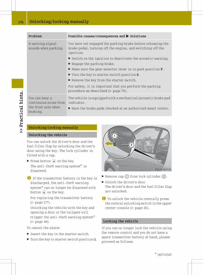
Problem Possible causes/consequences and M Solutions
A warning signal
sounds when parking.
You have not engaged the parking brake before releasing the
brake pedal, turning off the engine, and switching off the
ignition.
X Switch on the ignition to deactivate the acoustic warning.
X Engage the parking brake.
X Make sure the gear selector lever is in park position P.
X Turn the key to starter switch position 0.
X Remove the key from the starter switch.
For safety, it is important that you perform the parking
procedure as described (Y page 79).
You can hear a
continuous noise from
the front axle when
braking.
The vehicle is equipped with a mechanical/acoustic brake pad
indicator.
X Have the brake pads checked at an authorized smart center.
Unlocking/locking manually
Unlocking the vehicle
You can unlock the driver’s door and the
fuel filler flap by unlocking the driver’s
door using the key. The lock cylinder is
fitted with a cap.
X Press button# on the key.
The anti-theft warning system* is
disarmed.
i If the transmitter battery in the key isdischarged, the anti-theft warning
system* can no longer be disarmed with
button# on the key.
For replacing the transmitter battery
(Y page 177).
Unlocking the vehicle with the key and
opening a door or the tailgate will
trigger the anti-theft warning system*
(Y page 48).
To cancel the alarm:
X Insert the key in the starter switch.
X Turn the key to starter switch position 1.
X Remove cap: from lock cylinder;.
X Unlock the driver’s door.
The driver’s door and the fuel filler flap
are unlocked.
i To unlock the vehicle centrally pressthe central unlocking switch in the upper
center console (Y page 26).
Locking the vehicle
If you can no longer lock the vehicle using
the remote control and you do not have a
spare transmitter battery at hand, please
proceed as follows:
176 Unlocking/locking manually>>Practicalhints.
* optional

X Open the driver’s door.
X Press the central locking switch
(Y page 54).
The indicator lamp on the central
locking switch comes on, when the starter
switch is in position 1.
The indicator lamp on the central
locking switch flashes, when the starter
switch is in position 0.
X Remove the key from the starter switch,
take it with you, and close all doors.
The vehicle is now locked and the anti-
theft warning system* is armed.
Closing the rear soft top
If the rear soft top does not lock properly
after being closed, proceed as follows:
X Stop the vehicle in a safe location.
X Engage the parking brake.
X Make sure the key is in starter switch
position 1.
X Fold up the rear soft top completely.
The rear soft top stops in the unlocked
position.
X Within one minute, press and hold symbol
G on the retractable soft top switch
for 15 seconds twice.
The rear soft top closes the locking
hooks.
X Close the retractable soft top
completely.
X Have the rear soft top checked at an
authorized smart center.
Replacing transmitter battery
Notes
The remote control’s transmitter battery is
almost spent when the turn signals flash
rapidly nine times in a row when locking
the vehicle.
i If you do not replace the transmitterbattery, after about 100 more times you
will no longer be able to lock or unlock
the vehicle using the remote control.
X Replace the transmitter battery.
or
X Have the transmitter battery replaced at
an authorized smart center.
G WARNING
Batteries contain poisonous and corrosive
substances. Therefore keep the batteries
out of reach of children.
If a battery is swallowed, seek medical help
immediately.
Batteries contain materials that can harm
the environment if disposed of improperly.
Recycling of batteries is the preferred
method of disposal. Many states/provinces
require sellers of batteries to accept old
batteries for recycling.
Replacing battery
Replacement battery: CR 2016 button cell
! Replace the remote control’stransmitter battery every two years at
the latest. Otherwise there is a danger of
leakage. The remote control could be
damaged.
Replacing transmitter battery 177
>>Practicalhints.
* optional Z

X Insert a suitable object such as a coin
into the slot at the eyelet of the key
housing.
X Carefully turn the coin until key housing
top half: is unlatched.
X Open key housing top half: to the side.
X Remove transmitter battery; from the
board.
! Check the polarity when inserting thenew transmitter battery. You could
otherwise damage parts of the electrical
system. When inserting the batteries,
make sure they are clean and free of lint.
X Insert the new transmitter battery.
X Press both halves of the key housing
together again.
X Check the operation of the remote
control.
Replacing bulbs
About replacing bulbs
Safe vehicle operation depends on proper
exterior lighting and signaling. It is
therefore essential that all bulbs and lamp
assemblies are in good working order at all
times.
Correct headlamp adjustment is extremely
important. Have headlamps checked and
readjusted at regular intervals and when a
bulb has been replaced. Contact an
authorized smart center for headlamp
adjustment.
G WARNING
Bulbs and bulb sockets can be very hot.
Allow the lamp to cool down before changing
a bulb. Otherwise you could be burned if you
touch them.
Keep bulbs out of the reach of children.
Halogen lamps contain pressurized gas. A
bulb can explode if you:
Rtouch or move it when hot
Rdrop the bulb
Rscratch the bulb
Wear eye and hand protection.
i If the headlamps or front fog lamps* arefogged up on the inside as a result of
high humidity, driving the vehicle a
distance with the lights on should clear
up the fogging.
Notes on bulb replacement:
ROnly use bulbs of the same type and with
the specified watt rating.
RSwitch the lights off before replacing a
bulb to prevent short circuits.
RAlways use a clean lint-free cloth when
handling bulbs.
RYour hands should be dry and free of oil
and grease.
RAvoid touching the glass of the bulb with
bare fingers.
RIf the newly installed bulb does not come
on, contact an authorized smart center.
RHave the bulbs for the front fog lamps*
and the LED daytime running lamps*
replaced at an authorized smart center.
178 Replacing bulbs>>Practicalhints.
* optional
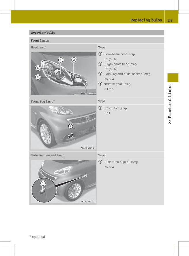
Overview bulbs
Front lamps
Headlamp Type
: Low‑beam headlamp
H7 (55 W)
; High‑beam headlamp
H7 (55 W)
= Parking and side marker lamp
WY 5 W
? Turn signal lamp
2357 A
Front fog lamp* Type
: Front fog lamp
H 11
Side turn signal lamp Type
: Side turn signal lamp
WY 5 W
Replacing bulbs 179
>>Practicalhints.
* optional Z

Rear lamps
Tail lamp unit Type
: Brake lamp/tail lamp/turn signal
lamp/side marker lamp
12 V 21/5 W
; Reflector
-
= Backup lamp
12 V 21 W
License plate lamps Type
: License plate lamps
C 5 W
High‑mounted brake lamp Type
: High‑mounted brake lamp
W 16 W
180 Replacing bulbs>>Practicalhints.
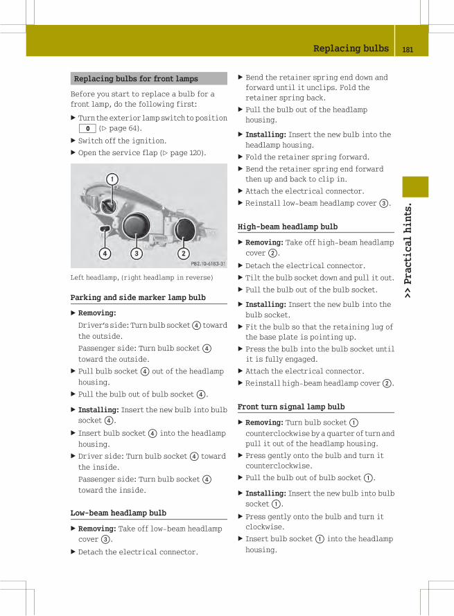
Replacing bulbs for front lamps
Before you start to replace a bulb for a
front lamp, do the following first:
X Turn the exterior lamp switch to position
$ (Y page 64).
X Switch off the ignition.
X Open the service flap (Y page 120).
Left headlamp, (right headlamp in reverse)
Parking and side marker lamp bulb
X Removing:
Driver’s side: Turn bulb socket? toward
the outside.
Passenger side: Turn bulb socket?
toward the outside.
X Pull bulb socket? out of the headlamp
housing.
X Pull the bulb out of bulb socket?.
X Installing: Insert the new bulb into bulb
socket?.
X Insert bulb socket? into the headlamp
housing.
X Driver side: Turn bulb socket? toward
the inside.
Passenger side: Turn bulb socket?
toward the inside.
Low‑beam headlamp bulb
X Removing: Take off low‑beam headlamp
cover=.
X Detach the electrical connector.
X Bend the retainer spring end down and
forward until it unclips. Fold the
retainer spring back.
X Pull the bulb out of the headlamp
housing.
X Installing: Insert the new bulb into the
headlamp housing.
X Fold the retainer spring forward.
X Bend the retainer spring end forward
then up and back to clip in.
X Attach the electrical connector.
X Reinstall low‑beam headlamp cover=.
High‑beam headlamp bulb
X Removing: Take off high‑beam headlamp
cover;.
X Detach the electrical connector.
X Tilt the bulb socket down and pull it out.
X Pull the bulb out of the bulb socket.
X Installing: Insert the new bulb into the
bulb socket.
X Fit the bulb so that the retaining lug of
the base plate is pointing up.
X Press the bulb into the bulb socket until
it is fully engaged.
X Attach the electrical connector.
X Reinstall high‑beam headlamp cover;.
Front turn signal lamp bulb
X Removing: Turn bulb socket:
counterclockwise by a quarter of turn and
pull it out of the headlamp housing.
X Press gently onto the bulb and turn it
counterclockwise.
X Pull the bulb out of bulb socket:.
X Installing: Insert the new bulb into bulb
socket:.
X Press gently onto the bulb and turn it
clockwise.
X Insert bulb socket: into the headlamp
housing.
Replacing bulbs 181
>>Practicalhints.
Z

The arrow on bulb socket: must be in
line with the line on the headlamp
housing.
X Turn bulb socket: clockwise by a
quarter of turn.
Side turn signal lamp bulb
X Removing: Open the door on the
corresponding side.
X Press on retaining lug: in the
direction of the arrow until the side turn
signal lamp housing disengages.
X Close the door.
X Use a suitable tool to loosen the side turn
signal lamp housing from the fender.
X Turn the bulb socket counterclockwise
and pull it out of the side turn signal
lamp housing.
X Pull the bulb out of the bulb socket.
X Installing: Insert the new bulb into the
bulb socket.
X Insert the bulb socket into the side turn
signal lamp housing and turn the bulb
socket clockwise.
X Fit the side turn signal lamp housing
onto the fender.
X Press gently onto the side turn signal
lamp housing.
The side turn signal lamp housing must
audibly engage.
Replacing bulbs for rear lamps
Before you start to replace a bulb for a rear
lamp, do the following first:
X Turn exterior lamp switch to position
$ (Y page 64).
X Switch off the ignition.
Tail lamp unit
X Removing:
Coupé: Open the upper tailgate.
X Open the lower tailgate.
X Cabriolet: Open the rear soft top
(Y page 73).
X Remove the side cover in the cargo
compartment on the corresponding side.
X Fold the damping material forward, if
necessary.
Left bulb carrier illustrated as example
: Retaining tab
; Electrical connector
X Press retaining tab: in the center of
the bulb carrier upwards.
X Pull the bulb carrier out of the tail lamp
housing.
182 Replacing bulbs>>Practicalhints.

Left bulb carrier with bulb sockets (right bulbcarrier in reverse)
: Retaining tab
= Brake, tail, turn signal and side marker
lamp bulb
? Backup lamp bulb
X Depending on which bulb needs to be
replaced, press gently onto bulb=
or? and turn it counterclockwise.
X Pull the bulb out of the bulb socket.
X Installing: Insert the new bulb into the
bulb socket.
X Press gently onto the bulb and turn it
clockwise until it engages.
X Insert the bulb carrier into the tail lamp
housing.
X Press gently onto the bulb carrier.
Let retaining tab: engage.
X Fold the damping material backward, if
necessary.
X Reinstall the side cover in the cargo
compartment.
High-mounted brake lamp
X Removing: Unscrew retaining screws:.
X Remove high-mounted brake lamp?.
X Detach electrical connector; frombulb
socket=.
X Turn the bulb counterclockwise and pull
it out of its socket.
X Installing: Install in the reverse order.
License plate lamps
G WARNING
High outside temperature, stop-and-go
traffic, driving on long uphill grades, or
driving at high engine speed may increase
the temperature in the engine
compartment. Therefore the area around the
air slots in the rear apron may be hot. Let
the engine cool off before touching this
area to prevent burns.
Replacing bulbs 183
>>Practicalhints.
Z

X Use a suitable tool to loosen the
corresponding license plate lamp unit at
jacking point:.
X Carefully unclip the license plate lamp
unit.
X Detach electrical connectors;.
X Remove bulb=.
X Insert the new bulb.
X Attach electrical connectors;.
X Fit the license plate lamp unit on the
right and press gently on the left.
The license plate lamp unit must audibly
engage.
Replacing interior lighting lamps
A 12 V/10 W bulb is required.
X Removing: Use a flat object to pry the
lamp lens: off from the passenger side.
X Detach electrical connector; from the
interior lamp.
X Remove bulb= from mount?.
X Installing: Insert the new bulb.
X Attach electrical connector; to the
interior lamp.
X Fit the lamp lens on the left in the
opening and press gently on the right.
The lamp lens must audibly engage.
Replacing wiper blades
About replacing wiper blades
G WARNING
For safety reasons, switch off the wipers
and remove the key from the starter switch
before replacing a wiper blade. The
windshield wipers could otherwise be set
in motion and cause injury.
G WARNING
Wiper blades are components that are
subject to wear and tear. Replace the wiper
blades at least twice a year, preferably in
the spring and fall. Otherwise the windows
will not be properly wiped. As a result, you
may not be able to observe surrounding
traffic conditions and could cause an
accident.
! Hold on to the wiper when folding thewiper arm back. If released, the force of
the impact from the windshield wiper
184 Replacing wiper blades>>Practicalhints.

tensioning spring could crack the
windshield.
Do not allow the wiper arms to contact the
windshield glass without a wiper blade
inserted.
We recommend that you have this work
carried out at an authorized smart
center.
To ensure proper visibility
Rit is vital that you have wiper blades that
are in perfect shape
Rclean the wiper blades regularly with a
cleaning agent
Rremove any tough dirt stains with a
sponge or brush
Windshield wiper blades
! Do not pull on the wiper blade inserts.They could tear.
Removing
X Remove the key from the starter switch.
X Fold wiper arm? away from the
windshield until it snaps into place.
X Press on retaining springs; on both
sides of wiper blade:.
X Fold wiper blade: away from wiper
arm? in direction of arrow=.
X Detach wiper blade: in direction of
arrowA.
Installing
X With guide tabA sliding into opening
B, attach new wiper blade: onto the
wiper arm.
X Fold wiper blade: towards the wiper
arm in direction of arrow=.
Retaining springs; must audibly
engage in attachment?.
X Check whether wiper blade: is securely
fastened.
X Fold the wiper arm backward to rest on
the windshield.
Make sure to hold on to the wiper when
folding it back.
! Make sure the wiper blades are properlyinstalled. Improperly installed wiper
blades may cause windshield damage.
Rear window wiper blade
Replacing wiper blades 185
>>Practicalhints.
Z

X Removing: Fold the wiper arm away from
the rear window until you feel it engage.
X Fold wiper blade: away from the wiper
arm in direction of arrow; until it
disengages from its mounting.
X Detach wiper blade:.
X Installing: Push the new wiper blade onto
the wiper arm until you feel it engage.
X Fold the wiper blade into a position
parallel to the wiper arm.
X Fold the wiper arm backward to rest on
the rear window.
Make sure to hold on to the wiper when
folding the wiper arm back.
! Make sure the wiper blade is properlyinstalled. An improperly installed
wiper blade may cause rear window
damage.
Adjusting the washer jet nozzles
: Front washer jet nozzles
; Rear washer jet nozzles
X Adjusting: Use a needle to move washer
jet nozzles: or; left, right, up, or
down.
i Check the setting of the washer jetnozzles at regular intervals. The washer
jet nozzles are correctly set when the
water jet hits the windshield or the rear
window approximately in the center.
Flat tire
Preparing the vehicle
Upon experiencing any type of problem
with the vehicle’s tires, switch on the
hazard warning flasher, carefully slow
down and exit the roadway in a cautious
manner.
X Park the vehicle at a safe distance from
moving traffic on a hard, flat surface
when possible.
X Make sure the tire valve of the damaged
tire is located below the horizontal axle
of the wheel hub.
X Engage the parking brake.
X Turn the steering wheel so that the front
wheels are in a straight ahead position.
X Move the gear selector lever to park
position P.
X Turn off the engine.
X Remove the key from the starter switch
and take the key with you.
i Open door only when conditions are safeto do so.
X Have any passenger exit the vehicle at a
safe distance from the roadway.
Using the tire repair kit
! Depending on the type of damage on thetire, the tire sealant could damage the
sensor of the Tire Pressure Monitoring
System (TPMS)*. Such damage is not
covered by the smart Limited Warranty.
When having the damaged tire replaced,
also have the TPMS sensors* checked for
proper function. When the sensor is
damaged, the TPMS* will not function
properly. The sensor must then be
replaced at an authorized smart center as
soon as possible.
i Depending on production date of yourvehicle, it will be equipped with version
1 or version 2 of the tire repair kit.
186 Flat tire>>Practicalhints.
* optional

Please make sure to refer to the
description of the tire repair kit in your
vehicle before sealing a tire.
The tire repair kit can be used to seal
punctures of up to approximately 0.16 in
(4 mm) on the tire tread.
The tire repair kit enables you to drive on
the sealed tire to the nearest authorized
smart center.
X You should have the sealed tire replaced
at an authorized smart center.
G WARNING
Take care not to allow the contents of the
tire sealant to come in contact with hair,
eyes or clothing. The tire sealant is
harmful if inhaled, swallowed or absorbed
through the skin - causes skin, eye and
respiratory irritation. Wear gloves while
using this product if they are available.
Any contact with eyes or skin should be
flushed immediately with plenty of water.
If clothing comes in contact with the tire
sealant, change clothing as soon as
possible.
In case of allergic reaction or rash, consult
a physician immediately.
Notes
RSmall tire punctures, particularly those
in the tread, can be sealed with the tire
sealant.
RThe tire sealant can be used in ambient
temperatures from ‑4¦ (‑20¥) to
104¦ (+40¥).
RDo not remove any foreign objects such as
nails or screws that have penetrated the
tire.
RDo not use the tire sealant if the tire has
been damaged by being driven when
insufficiently inflated (e.g. bumps,
cuts, cracks etc. on the tire).
RAllow escaped tire sealant to dry, then
peel it off.
RImmediately wash all painted surfaces
that came into contact with the tire
sealant using a damp cloth.
RAvoid skin and eye contact with the tire
sealant.
RDo not swallow the tire sealant.
RAllow the tire sealant that is inside the
damaged tire to dry and dispose of
together with the tire.
RDo not use the tire sealant after the
expiration date has elapsed (see top of
container).
Instead, have it replaced at an
authorized smart center.
G WARNING
The tire sealant is a limited repair device.
The tire sealant cannot be used for cuts or
punctures larger than approximately
0.16 in (4 mm) and tire damage caused by
driving with extremely low tire inflation
pressure, or on a flat tire, or a damaged
wheel.
Do not drive the vehicle under such
circumstances.
If you are unsure of the condition of the tire
or have any question whatsoever about its
suitability for driving contact the nearest
smart center for assistance or call
Roadside Assistance.
G WARNING
Please review the instructions below for
using the tire repair kit. If you are not
confident that you can competently follow
the instructions for using this kit, do not
use the kit, but instead call for Roadside
Assistance.
G WARNING
Keep the tire sealant out of reach of
children. If swallowed, rinse mouth
immediately with plenty of water and drink
plenty of water.
Do not induce vomiting!
Consult a physician immediately.
Flat tire 187
>>Practicalhints.
Z
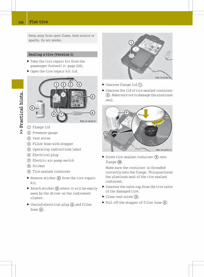
Keep away from open flame, heat source or
sparks. Do not smoke.
Sealing a tire (Version 1)
X Take the tire repair kit from the
passenger footwell (Y page 158).
X Open the tire repair kit lid.
: Flange lid
; Pressure gauge
= Vent screw
? Filler hose with stopper
A Operating instructions label
B Electrical plug
C Electric air pump switch
D Sticker
E Tire sealant container
X Remove stickerD from the tire repair
kit.
X Attach stickerD where it will be easily
seen by the driver on the instrument
cluster.
X Unwind electrical plugB and filler
hose?.
X Unscrew flange lid:.
X Unscrew the lid of tire sealant container
E. Make sure not to damage the aluminum
seal.
X Screw tire sealant containerE onto
flangeF.
Make sure the container is threaded
correctly onto the flange. This punctures
the aluminum seal of the tire sealant
container.
X Unscrew the valve cap from the tire valve
of the damaged tire.
X Close vent screw=.
X Pull off the stopper of filler hose?.
188 Flat tire>>Practicalhints.
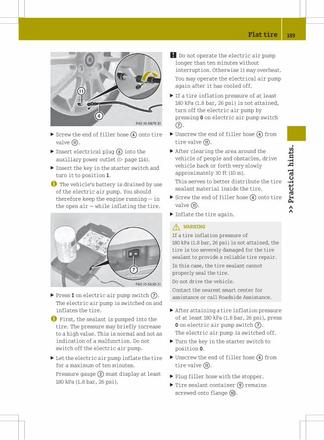
X Screw the end of filler hose? onto tire
valveG.
X Insert electrical plugB into the
auxiliary power outlet (Y page 114).
X Insert the key in the starter switch and
turn it to position 1.
i The vehicle’s battery is drained by useof the electric air pump. You should
therefore keep the engine running — in
the open air — while inflating the tire.
X Press I on electric air pump switchC.
The electric air pump is switched on and
inflates the tire.
i First, the sealant is pumped into thetire. The pressure may briefly increase
to a high value. This is normal and not an
indication of a malfunction. Do not
switch off the electric air pump.
X Let the electric air pump inflate the tire
for a maximum of ten minutes.
Pressure gauge; must display at least
180 kPa (1.8 bar, 26 psi).
! Do not operate the electric air pumplonger than ten minutes without
interruption. Otherwise it may overheat.
You may operate the electrical air pump
again after it has cooled off.
X If a tire inflation pressure of at least
180 kPa (1.8 bar, 26 psi) is not attained,
turn off the electric air pump by
pressing 0 on electric air pump switch
C.
X Unscrew the end of filler hose? from
tire valveG.
X After clearing the area around the
vehicle of people and obstacles, drive
vehicle back or forth very slowly
approximately 30 ft (10 m).
This serves to better distribute the tire
sealant material inside the tire.
X Screw the end of filler hose? onto tire
valveG.
X Inflate the tire again.
G WARNING
If a tire inflation pressure of
180 kPa (1.8 bar, 26 psi) is not attained, the
tire is too severely damaged for the tire
sealant to provide a reliable tire repair.
In this case, the tire sealant cannot
properly seal the tire.
Do not drive the vehicle.
Contact the nearest smart center for
assistance or call Roadside Assistance.
X After attaining a tire inflation pressure
of at least 180 kPa (1.8 bar, 26 psi), press
0 on electric air pump switchC.
The electric air pump is switched off.
X Turn the key in the starter switch to
position 0.
X Unscrew the end of filler hose? from
tire valveG.
X Plug filler hose with the stopper.
X Tire sealant containerE remains
screwed onto flangeF.
Flat tire 189
>>Practicalhints.
Z

X Place the tire repair kit securely in the
vehicle.
X Drive off immediately.
The tire sealant will distribute itself
evenly inside the tire.
G WARNING
Do not exceed vehicle speed of 50 mph
(80 km/h). A tire sealant repair is not
designed to operate at higher speeds.
The sticker must be attached on the
instrument cluster where it will be easily
seen by the driver.
Vehicle handling characteristics of a tire
sealant repaired tire may change. Adapt
your driving accordingly.
X After driving for about 1.8 miles (3 km)
or ten minutes, stop and exit the vehicle
taking all of the appropriate safety
precautions.
X Take the tire repair kit from the vehicle.
X Screw the end of filler hose? onto tire
valveG.
X Check the tire inflation pressure using
pressure gauge;.
G WARNING
If tire inflation pressure has fallen below
130 kPa (1.3 bar, 19 psi) do not continue to
drive the vehicle.
Park your vehicle safely away from the
roadway and contact the nearest smart
center or call Roadside Assistance.
Have the damaged tire replaced.
X If the tire inflation pressure is at least
130 kPa (1.3 bar, 19 psi), inflate or deflate
the tire to correct tire inflation
pressure (see Tire and Loading
Information placard located on the
driver’s door B‑pillar).
RTo increase the tire inflation
pressure: Switch on the electric air
pump.
RTo decrease the tire inflation
pressure: Open vent screw=. Recheck
the tire inflation pressure with the
electric air pump’s pressure gauge.
X After checking the tire inflation
pressure, unscrew the end of filler
hose? from tire valveG.
X Screw the valve cap onto the tire valve.
X Plug filler hose with the stopper.
X Place the tire repair kit securely in the
vehicle.
! The manufacturer is unable toguarantee that all tire punctures can be
repaired with the tire repair kit, in
particular cuts or perforations larger
than approximately 0.16 in (4 mm) or away
from the tire’s tread. The manufacturer
is not liable for damage sustained
through improper use of the tire repair
kit.
G WARNING
Follow recommended tire inflation
pressures.
Do not underinflate tires. Underinflated
tires wear excessively and/or unevenly,
adversely affect handling and fuel
economy, and are more likely to fail from
being overheated.
Do not overinflate tires. Overinflated
tires can adversely affect handling and
ride comfort, wear unevenly, increase
stopping distance, and result in sudden
deflation (blowout) because they are more
likely to become punctured or damaged by
road debris, potholes etc.
Do not overload the tires by exceeding the
specified load limit as indicated on the
Tire and Loading Information placard on
the driver’s door B‑pillar. Overloading the
tires can overheat them, possibly causing
a blowout. Overloading the tires can also
190 Flat tire>>Practicalhints.
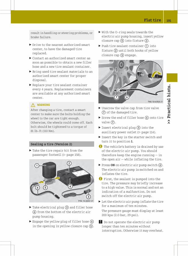
result in handling or steering problems, or
brake failure.
X Drive to the nearest authorized smart
center, to have the damaged tire
replaced.
X Contact an authorized smart center as
soon as possible to obtain a new filler
hose and a new tire sealant container.
X Bring used tire sealant materials to an
authorized smart center for proper
disposal.
X Replace your tire sealant container
every 4 years. Replacement containers
are available at any authorized smart
center.
G WARNING
After changing a tire, contact a smart
center to make sure the bolts holding the
wheel to the car are tight enough.
Otherwise, the wheels could come off. Each
bolt should be tightened to a torque of
81 lb‑ft (110 Nm).
Sealing a tire (Version 2)
X Take the tire repair kit from the
passenger footwell (Y page 158).
X Take electrical plug= and filler hose
B from the bottom of the electric air
pump housing.
X Engage the yellow plug of filler hoseB
in the opening in yellow closure capA.
X With the O-ring seals towards the
electric air pump housing, insert yellow
closure capA into fixture;.
X Push tire sealant container: into
fixture; until both hooks of yellow
closure capA engage.
X Unscrew the valve cap from tire valve
C of the damaged tire.
X Screw the end of filler hoseB onto tire
valveC.
X Insert electrical plug= into the
auxiliary power outlet (Y page 114).
X Insert the key in the starter switch and
turn it to position 1.
i The vehicle’s battery is drained by useof the electric air pump. You should
therefore keep the engine running — in
the open air — while inflating the tire.
X Press ON on electric air pump switch?.
The electric air pump is switched on and
inflates the tire.
i First, the sealant is pumped into thetire. The pressure may briefly increase
to a high value. This is normal and not an
indication of a malfunction. Do not
switch off the electric air pump.
X Let the electric air pump inflate the tire
for a maximum of ten minutes.
The pressure gauge must display at least
200 kpa (2.0 bar, 29 psi).
! Do not operate the electric air pumplonger than ten minutes without
interruption. Otherwise it may overheat.
Flat tire 191
>>Practicalhints.
Z

You may operate the electrical air pump
again after it has cooled off.
X If a tire inflation pressure of at least
200 kpa (2.0 bar, 29 psi) is not attained,
turn off the electric air pump by
pressing OFF on electric air pump
switch?.
X Unscrew the end of filler hose? from
tire valveC.
X After clearing the area around the
vehicle of people and obstacles, drive
vehicle back or forth very slowly
approximately 30 ft (10 m).
This serves to better distribute the tire
sealant material inside the tire.
X Screw the end of filler hose? onto tire
valveC.
X Inflate the tire again.
G WARNING
If a tire inflation pressure of
200 kPa (2.0 bar, 29 psi) is not attained, the
tire is too severely damaged for the tire
sealant to provide a reliable tire repair.
In this case, the tire sealant cannot
properly seal the tire.
Do not drive the vehicle.
Contact the nearest smart center for
assistance or call Roadside Assistance.
X After attaining a tire inflation pressure
of at least 200 kPa (2.0 bar, 29 psi), press
OFF on electric air pump switch?.
The electric air pump is switched off.
X Turn the key in the starter switch to
position 0.
X Unscrew the end of filler hose? from
tire valveC.
X Place the tire repair kit securely in the
vehicle.
X Drive off immediately.
The tire sealant will distribute itself
evenly inside the tire.
G WARNING
Do not exceed vehicle speed of 50 mph
(80 km/h). A tire sealant repair is not
designed to operate at higher speeds.
The sticker must be attached on the
instrument cluster where it will be easily
seen by the driver.
Vehicle handling characteristics of a tire
sealant repaired tire may change. Adapt
your driving accordingly.
X After driving for about 1.8 miles (3 km)
or ten minutes, stop and exit the vehicle
taking all of the appropriate safety
precautions.
X Take the tire repair kit from the vehicle.
X Screw the end of filler hose? onto tire
valveC.
X Check the tire inflation pressure using
pressure gaugeE.
G WARNING
If tire inflation pressure has fallen below
130 kPa (1.3 bar, 19 psi) do not continue to
drive the vehicle.
Park your vehicle safely away from the
roadway and contact the nearest smart
center or call Roadside Assistance.
Have the damaged tire replaced.
X If the tire inflation pressure is at least
130 kPa (1.3 bar, 19 psi), inflate or deflate
the tire to correct tire inflation
pressure (see Tire and Loading
192 Flat tire>>Practicalhints.

Information placard located on the
driver’s door B‑pillar).
RTo increase the tire inflation
pressure: Switch on the electric air
pump.
RTo decrease the tire inflation
pressure: Press deflate buttonD.
Recheck the tire inflation pressure
with the electric air pump’s pressure
gaugeE.
X When the tire inflation pressure is
correct, unscrew the end of filler
hose? from tire valveC.
X Screw the valve cap onto the tire valve.
X To detach tire sealant container: from
the electric air pump, press both
latches.
X Pull tire sealant container: out of
fixture;.
Filler hose? remains on tire sealant
container:.
X Place the tire repair kit securely in the
vehicle.
! The manufacturer is unable toguarantee that all tire punctures can be
repaired with the tire repair kit, in
particular cuts or perforations larger
than approximately 0.16 in (4 mm) or away
from the tire’s tread. The manufacturer
is not liable for damage sustained
through improper use of the tire repair
kit.
G WARNING
Follow recommended tire inflation
pressures.
Do not underinflate tires. Underinflated
tires wear excessively and/or unevenly,
adversely affect handling and fuel
economy, and are more likely to fail from
being overheated.
Do not overinflate tires. Overinflated
tires can adversely affect handling and
ride comfort, wear unevenly, increase
stopping distance, and result in sudden
deflation (blowout) because they are more
likely to become punctured or damaged by
road debris, potholes etc.
Do not overload the tires by exceeding the
specified load limit as indicated on the
Tire and Loading Information placard on
the driver’s door B‑pillar. Overloading the
tires can overheat them, possibly causing
a blowout. Overloading the tires can also
result in handling or steering problems, or
brake failure.
X Drive to the nearest authorized smart
center, to have the damaged tire
replaced.
X Contact an authorized smart center as
soon as possible to obtain a new filler
hose and a new tire sealant container.
X Bring used tire sealant materials to an
authorized smart center for proper
disposal.
X Replace your tire sealant container
every 4 years. Replacement containers
are available at any authorized smart
center.
G WARNING
After changing a tire, contact a smart
center to make sure the bolts holding the
wheel to the car are tight enough.
Otherwise, the wheels could come off. Each
bolt should be tightened to a torque of
81 lb‑ft (110 Nm).
Flat tire 193
>>Practicalhints.
Z

Wheel change
Preparing the vehicle
X Park the vehicle on a hard, flat surface
when possible.
X Turn on the hazard warning flasher.
X Turn the steering wheel so that the front
wheels are in a straight-ahead position.
X Engage the parking brake.
X Move the gear selector lever to park
position P.
X Turn off the engine.
X Have any passenger exit the vehicle at a
safe distance from the roadway.
Removing the wheel
G WARNING
When jacking up the vehicle, only use a
suitable jack. Observe the manufacturer’s
safety instructions.
The jack must be designed for jacking up
this vehicle at the jack take-up brackets
built into both sides of the vehicle.
The jack is intended only for lifting the
vehicle briefly for wheel changes. It is not
suited for performing maintenance work
under the vehicle. To help avoid personal
injury, use the jack only to lift the vehicle
during a wheel change.
Never get beneath the vehicle while it is
supported by the jack. Keep hands and feet
away from the area under the lifted vehicle.
Always lower the vehicle onto sufficient
capacity jackstands before working under
the vehicle.
Always firmly engage the parking brake and
block the wheels with wheel chocks or other
sizeable objects before raising the
vehicle with the jack. Do not release the
parking brake while the vehicle is raised.
Make sure the ground on which the vehicle
is standing and where you place the jack is
solid, level and not slippery. If necessary,
use a large underlay. On slippery surfaces,
such as tiled floors, you should use a non-
slip underlay, for example a rubber mat.
Do not use wooden blocks or similar objects
to support the jack. Otherwise the jack may
not be able to achieve its load-bearing
capacity if it is not at its full height.
The jack must always be vertical when in
use. Always try to use the jack on level
surface. If you do not position the jack
correctly, the vehicle can fall off the jack
and seriously or fatally injure you or
others.
Never start the engine when the vehicle is
raised.
Also observe the notes on the jack.
X Make sure to have a suitable jack18, wheel
wrench18 and wheel chock18.
Contact an authorized smart center for
information on which jack and wheel
wrench are required.
X Prepare the vehicle as described
(Y page 194).
X Make sure the surface is level.
Prevent the vehicle from rolling away by
blocking wheels with wheel chocks or other
sizeable objects:
X Place one wheel chock or other sizeable
object in front of and another wheel
chock or other sizeable object behind
the wheel that is diagonally opposite to
the wheel being changed.
18 Not included and not available as factory equipment.
194 Wheel change>>Practicalhints.

Steel rim with wheel cover
X Vehicles with wheel cover on steel rim:
Pull the wheel cover off of the rim.
If necessary, use a suitable tool to pry
the wheel cover off.
X On wheel to be changed, loosen but do not
yet remove the wheel bolts
(approximately one full turn with wheel
wrench).
Steel rim with wheel trim cap
X Vehicles with wheel trim cap on steel
rim: On wheel to be changed, loosen but
do not yet remove the wheel bolts
(approximately one full turn with wheel
wrench).
X Take the wheel trim cap off.
X Position jack; under take-up
bracket: so that it is always vertical
as seen from the side, even if the vehicle
is parked on an incline.
The take-up brackets are identified by
the embossed recesses in the area of the
door sills.
! Only position the jack on thedesignated take-up brackets. Otherwise,
the vehicle could be damaged.
X Jack up the vehicle until the wheel is a
maximum of 1.2 in (3 cm) from the ground.
X Unscrew and remove the wheel bolts.
! Do not place wheel bolts in sand or dirt.This could result in damage to the wheel
bolts and wheel hub threads.
X Remove the wheel.
Mounting the wheel
G WARNING
Always replace wheel bolts that are
damaged or rusted.
Never apply oil or grease to wheel bolts.
Damaged wheel hub threads should be
repaired immediately. Do not continue to
drive under these circumstances! Contact
an authorized smart center or call Roadside
Assistance.
Incorrect wheel bolts or improperly
tightened wheel bolts can cause the wheel
Wheel change 195
>>Practicalhints.
Z

to come off. This could cause an accident.
Be sure to use the correct wheel bolts.
G WARNING
Only use genuine smart wheel bolts. Other
wheel bolts may come loose.
Do not tighten the wheel bolts when the
vehicle is raised. Otherwise the vehicle
could fall off the jack.
X Clean contact surfaces of wheel and wheel
hub.
! To avoid paint damage, place wheel flatagainst hub and hold it there while
installing first wheel bolt.
X Guide the wheel onto the wheel hub and
push it on.
X Insert two wheel bolts and tighten them
slightly.
X Vehicles with wheel trim cap on steel
rim: Attach the wheel trim cap so that it
is held by the two wheel bolts.
X Install last wheel bolt and tighten it
slightly.
X Lower the vehicle until the vehicle is
resting fully on its own weight.
X Remove the jack.
X Tighten the wheel bolts. Observe a
tightening torque of 80 lb-ft (110 Nm).
G WARNING
Have the tightening torque checked after
changing a wheel. The wheels could come
loose if they are not tightened to a torque
of 80 lb-ft (110 Nm).
Steel rim with wheel cover
X Vehicles with wheel cover on steel rim:
Position wheel cover aperture: so
valve; fits through.
X Push the wheel cover evenly onto the
wheel rim with both hands.
X Check that the wheel cover is fixed
securely to the wheel rim.
i The Tire Pressure Monitoring System
(TPMS)* only functions on wheels that are
equipped with the proper electronic
sensors (Y page 128).
Battery
About the battery
Your vehicle’s battery is located in the
passenger footwell below the footrest
(Y page 198).
The battery should always be sufficiently
charged in order to achieve its rated
service life. Refer to the Scheduled
Maintenance Guide (USA only) or the
Service booklet (Canada only) for battery
maintenance intervals.
If you use your vehicle mostly for short-
distance trips, you will need to have the
battery charge checked more frequently.
When replacing the battery, always use
batteries approved by smart.
Battery: 12 V and 42 Ah
196 Battery>>Practicalhints.
* optional

If you do not intend to operate your vehicle
for an extended period of time, consult an
authorized smart center about steps you
need to observe.
G WARNING
Observe all safety instructions and
precautions when handling automotive
batteries.
Risk of explosion.
Fire, open flames and
smoking are prohibited
when handling batteries.
Avoid creating sparks.
Battery acid is caustic.
Do not allow it to come
into contact with skin,
eyes or clothing.
Wear suitable protective
clothing, especially
gloves, apron and
faceguard.
Wear eye protection.
Rinse any acid spills
immediately with clear
water. Contact a physician
if necessary.
Keep children away.
Follow the instructions in
this Operator’s Manual.
Batteries contain materials that can harm
the environment if disposed of improperly.
Recycling of batteries is the preferred
method of disposal. Many states require
sellers of batteries to accept old batteries
for recycling.
G WARNING
Failure to follow these instructions can
result in severe injury or death.
Observe all safety instructions and
precautions when handling automotive
batteries.
Never lean over batteries while
connecting, you might get injured.
Battery fluid contains sulfuric acid. Do not
allow this fluid to come in contact with
eyes, skin or clothing. In case it does,
immediately flush affected area with water
and seek medical help if necessary.
A battery will also produce hydrogen gas,
which is flammable and explosive. Keep
flames or sparks away from battery, avoid
improper connection of jumper cables,
smoking, etc.
G WARNING
Do not place any metal objects on a battery.
You could otherwise cause a short circuit
and the battery’s highly flammable
chemicals could ignite.
Never allow anymetal object to contact both
battery terminals or the positive terminal
and the vehicle body at the same time. This
might short circuit the battery and ignite
the highly flammable and explosive
hydrogen gas generated by the battery,
causing serious personal injury.
G WARNING
Keep flames or sparks away from battery,
avoid improper connection of jumper
cables, smoking, etc.
RWhen disconnecting the battery, always
disconnect the negative terminal first,
followed by positive terminal.
RWhen connecting the battery, always
connect the positive terminal first,
followed by the negative terminal.
RDo not loosen or disconnect the battery
terminal clips while the engine is
Battery 197
>>Practicalhints.
Z

running or the key is in the starter
switch.
! Never loosen or detach battery terminalclamps while the engine is running or the
key is in the starter switch. Otherwise
the alternator and other electronic
components could be severely damaged.
Have the battery checked regularly at an
authorized smart center.
Refer to Maintenance Booklet for
maintenance intervals or contact an
authorized smart center for further
information.
! Never invert the terminal connections!
Disconnecting, removing, charging,
reinstalling and reconnecting the
battery
Disconnecting the battery
i If the battery is disconnected or
discharged
Rthe key will not turn in the starter
switch
Rthe automatic transmission will
remain in park position P
For more information see “Jump
starting” (Y page 199).
X Engage the parking brake.
X Move the gear selector lever to park
position P.
X Turn off all electrical accessories.
X Turn off the engine.
X Open the passenger door.
X Move the passenger seat to the rear as far
as possible.
X Unscrew the carpet holder in the
passenger footwell (Y page 158).
X Lift the carpet.
X Unscrew fastening screw;
counterclockwise.
X Pull footrest: sideways out of the
vehicle.
X Read and observe safety instructions and
precautions (Y page 196).
! Always disconnect the battery in theorder described below. Otherwise the
vehicle’s electronics can be damaged.
X Disconnect the battery negative lead
from negative terminal=.
Make sure the negative lead does not
come into contact with the positive lead.
X Remove cover? from the positive
terminal.
X Disconnect the battery positive lead.
Removing the battery
X Unscrew battery mountA.
X Remove the battery support and bracket.
X Pull out the ventilation hose from the
battery (depending on battery
198 Battery>>Practicalhints.

arrangement in your vehicle model, the
ventilation hose is located either on the
left or right side of the battery).
X Remove the battery.
Charging the battery
G WARNING
Avoid creating sparks when charging the
battery as escaping gases are flammable.
Keep open flames away from the battery and
do not smoke.
Do not touch the battery terminal withmetal
objects and do not remove the battery
charger’s terminal clamps until the battery
charger has been switched off and no
further gas is being discharged by the
batteries.
Only charge the battery in a well ventilated
area.
There is a risk of acid burns during the
charging procedure due to the gases which
escape from the battery. Do not lean over
the battery when it is being charged.
G WARNING
Never charge a battery while still installed
in the vehicle. Gases may escape during
charging and cause explosions that may
result in paint damage, corrosion or
personal injury.
X Charge battery in accordance with the
instructions of the battery charger
manufacturer.
! Only use chargers of a correct andsuitable voltage.
! Never attempt to recharge a frozenbattery. Have the battery checked at a
smart center. The battery housing could
be damaged.
Reinstalling the battery
X Reinstall the charged battery. Follow the
previously described steps in reverse
order.
! The battery, its filler caps and theventilation hose must always be securely
installed when the vehicle is in
operation.
Reconnecting the battery
! Always connect the battery in the orderdescribed below. Otherwise the
vehicle’s electronics can be damaged.
X Turn off all electrical accessories.
X Remove the key from the starter switch.
! Never invert the terminal connections!
X Connect the battery positive lead and
fasten cover? (Y page 198).
X Connect battery negative lead=
(Y page 198).
i After battery power (e.g. due toreconnection) was interrupted, you will
have to set the clock (Y page 88).
i Have the battery’s charge status andacid level checked at the start of the cold
season at a smart center.
Jump starting
Notes
G WARNING
Failure to follow these directions will
cause damage to the electronic components,
and can lead to a battery explosion and
severe injury or death.
Never lean over batteries while connecting
or jump starting, you might get injured.
Battery fluid contains sulfuric acid. Do not
allow this fluid to come in contact with
eyes, skin or clothing. In case it does,
Jump starting 199
>>Practicalhints.
Z
immediately flush affected area with
water, and seek medical help if necessary.
A battery will also produce hydrogen gas,
which is flammable and very explosive.
Keep flames or sparks away from battery,
avoid improper connection of jumper
cables, smoking, etc.
Attempting to jump start a frozen battery
can result in it exploding, causing
personal injury.
Read all instructions before proceeding.
! Do not tow‑start vehicle. You couldotherwise seriously damage the
transmission which is not covered by the
smart Limited Warranty.
! Avoid repeated and lengthy startingattempts.
Do not attempt to start the engine using
a battery quick charge unit.
If the engine does not run after several
unsuccessful starting attempts, have it
checked at the nearest authorized smart
center.
Excessive unburned fuel generated by
repeated failed starting attempts may
damage the catalytic converter and may
present a fire risk.
Make sure the jumper cables do not have
loose or missing insulation.
Make sure the cable clamps do not touch
any other metal part while the other end
is still attached to a battery.
If the battery is discharged, the engine can
be started with jumper cables and the fully
charged battery of another vehicle or an
equivalent starter pack. Observe the
following:
RAccess to the battery is not possible on
all vehicles. If you cannot access the
battery in your vehicle provide jump
start power by an external battery or
starter pack.
RJump starting should only be performed
when the engine and catalytic converter
are cold.
RDo not start the engine if the battery is
frozen. Let the battery thaw out first.
ROnly jump start from batteries with the
same voltage rating (12 V). Jump starting
with a more powerful battery could
damage the vehicle’s electrical system.
Such damage will not be covered by the
smart Limited Warranty.
ROnly use jumper cables with sufficient
cross-section and insulated terminal
clamps.
RAlways make sure the jumper cables are
not on or near pulleys, fans or other parts
that move when an engine is started or
running.
RShould the battery be drained
completely, let the donating power
source charge the vehicle for several
minutes before reattempting the
starting process.
G WARNING
Keep flames or sparks away from battery. Do
not smoke.
Observe all safety instructions and
precautions when handling automotive
batteries.
200 Jump starting>>Practicalhints.
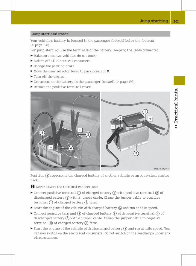
Jump start assistance
Your vehicle’s battery is located in the passenger footwell below the footrest
(Y page 198).
For jump starting, use the terminals of the battery, keeping the leads connected.
X Make sure the two vehicles do not touch.
X Switch off all electrical consumers.
X Engage the parking brake.
X Move the gear selector lever to park position P.
X Turn off the engine.
X Get access to the battery in the passenger footwell (Y page 198).
X Remove the positive terminal cover.
PositionA represents the charged battery of another vehicle or an equivalent starter
pack.
! Never invert the terminal connections!
X Connect positive terminal: of charged batteryA with positive terminal; of
discharged batteryB with a jumper cable. Clamp the jumper cable to positive
terminal: of charged batteryA first.
X Start the engine of the vehicle with charged batteryA and run at idle speed.
X Connect negative terminal= of charged batteryA with negative terminal? of
discharged batteryB with a jumper cable. Clamp the jumper cable to negative
terminal= of charged batteryA first.
X Start the engine of the vehicle with discharged batteryB and run at idle speed. You
can now switch on the electrical consumers. Do not switch on the headlamps under any
circumstances.
Jump starting 201
>>Practicalhints.
Z

X Remove the jumper cables from negative terminals= and? first.
X Remove the jumper cables from positive terminals: and;.
You can now switch on the headlamps.
X Remount the positive terminal cover.
X Have the battery checked at the nearest authorized smart center.
Towing
About towing
This section offers information on towing
methods for breakdown situations,
emergency towing, and flat towing smart
vehicles.
Recommended towing method -
Breakdown situation
smart recommends that the vehicle be
transported with all wheels off the ground
using a flatbed carrier truck or
appropriate wheel lift/dolly equipment.
X Switch off the tow‑away protection* and
interior motion sensor* (Y page 49).
! To prevent damage during transport, donot tie down the vehicle by its chassis or
suspension parts — use only wheel straps
to position and hold down the vehicle.
Improper tie down on a flatbed carrier
truck or trailer can damage suspension
parts and body panels.
Emergency towing
When circumstances do not permit the
recommended towing method, the vehicle
may be towed with all wheels on the ground
using a strap or tow bar connected to
another vehicle. Only tow the vehicle as far
as necessary to have the vehicle moved to a
safe location where the recommended
towing method can be employed.
G WARNING
If circumstances require towing the
vehicle with all wheels on the ground,
always tow with a tow bar if:
Rthe engine will not run
Rthere is a malfunction in the brake
system
Rthere is a malfunction in the power
supply or in the vehicle’s electrical
system
A tow bar is necessary to adequately control
the towed vehicle.
Prior to towing the vehicle with all wheels
on the ground, make sure the gear selector
lever is in neutral position N and the
ignition is switched off.
G WARNING
With the engine not running, there is no
power assistance for the brake and
steering* systems. In this case, it is
important to keep in mind that a
considerably higher degree of effort is
necessary to brake and steer the vehicle.
Adapt your driving accordingly.
! Do not tow the vehicle with the frontaxle raised. Doing so may cause serious
damage to the brake system which is not
covered by the smart Limited Warranty.
! Before towing the vehicle observe thefollowing instructions:
RDo not tow with sling-type equipment
attached to suspension parts. This may
202 Towing>>Practicalhints.
* optional

cause damage to the radiator and other
supports if towing on a bumpy road.
RTowing the vehicle should only be done
using the properly installed towing
eye bolt. Never attach a tow cable, tow
rope, or tow rod to the vehicle chassis,
frame, or suspension parts.
! Make sure the ignition is switched offwhile towing the vehicle. Doing
otherwise may result in
Rthe ESP® being activated. Active
braking action through the ESP® may
seriously damage the brake system
which is not covered by the smart
Limited Warranty.
Ra discharged battery.
! Make sure the gear selector lever is inneutral position N while towing the
vehicle. Doing otherwise may result in
significant transmission damage.
! Towing the vehicle with a luggage
rack* mounted is not permissible. The
vehicle must not be towed by the luggage
rack*.
i If the battery is disconnected ordischarged, the gear selector lever will
remain locked in park position P.
Contact an authorized smart center for
assistance or call Roadside Assistance.
Towing eye bolt
The towing eye bolt is located in the
passenger footwell under the carpet.
X Unscrew the carpet holder in the
passenger footwell (Y page 158).
X Lift the carpet.
X Take out towing eye bolt:.
Installing towing eye bolt
Depending of whether you are towing a
vehicle or being towed, the towing eye bolt
can be screwed into threaded holes which
are located behind covers on the front and
rear bumper.
Front cover
G WARNING
High outside temperature, stop-and-go
traffic, driving on long uphill grades, or
driving at high engine speed may increase
the temperature in the engine
compartment. Therefore the area around the
air slots in the rear apron may be hot. Let
the engine cool off before touching this
area to prevent burns.
Towing 203
>>Practicalhints.
* optional Z
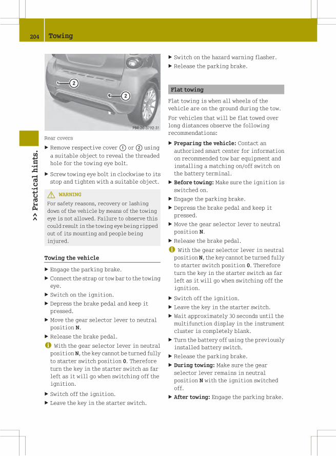
Rear covers
X Remove respective cover: or; using
a suitable object to reveal the threaded
hole for the towing eye bolt.
X Screw towing eye bolt in clockwise to its
stop and tighten with a suitable object.
G WARNING
For safety reasons, recovery or lashing
down of the vehicle by means of the towing
eye is not allowed. Failure to observe this
could result in the towing eye being ripped
out of its mounting and people being
injured.
Towing the vehicle
X Engage the parking brake.
X Connect the strap or tow bar to the towing
eye.
X Switch on the ignition.
X Depress the brake pedal and keep it
pressed.
X Move the gear selector lever to neutral
position N.
X Release the brake pedal.
i With the gear selector lever in neutralposition N, the key cannot be turned fully
to starter switch position 0. Therefore
turn the key in the starter switch as far
left as it will go when switching off the
ignition.
X Switch off the ignition.
X Leave the key in the starter switch.
X Switch on the hazard warning flasher.
X Release the parking brake.
Flat towing
Flat towing is when all wheels of the
vehicle are on the ground during the tow.
For vehicles that will be flat towed over
long distances observe the following
recommendations:
X Preparing the vehicle: Contact an
authorized smart center for information
on recommended tow bar equipment and
installing a matching on/off switch on
the battery terminal.
X Before towing: Make sure the ignition is
switched on.
X Engage the parking brake.
X Depress the brake pedal and keep it
pressed.
X Move the gear selector lever to neutral
position N.
X Release the brake pedal.
i With the gear selector lever in neutralposition N, the key cannot be turned fully
to starter switch position 0. Therefore
turn the key in the starter switch as far
left as it will go when switching off the
ignition.
X Switch off the ignition.
X Leave the key in the starter switch.
X Wait approximately 30 seconds until the
multifunction display in the instrument
cluster is completely blank.
X Turn the battery off using the previously
installed battery switch.
X Release the parking brake.
X During towing: Make sure the gear
selector lever remains in neutral
position N with the ignition switched
off.
X After towing: Engage the parking brake.
204 Towing>>Practicalhints.

X Turn the battery on using the previously
installed battery switch.
X Move the gear selector lever to park
position P.
X Remove the key from the starter switch.
X Lock the doors.
! Do not flat tow the vehicle with the frontaxle raised. Doing so may cause serious
damage to the brake system which is not
covered by the smart Limited Warranty.
! Failure to follow the recommendationsfor flat towing can cause damage to your
vehicle:
RNot following the battery disconnect
procedure in the proper sequence may
result in data loss in the vehicle’s
control units.
RNot disconnecting the battery and
leaving the key in starter switch
position 1 (ignition on) may result in
- the vehicle locking. The vehicle will
lock if the wheels are turning at
vehicle speeds of approximately
8 mph (14 km/h) or more.
- the ESP® being activated. Active
braking action through the ESP® may
seriously damage the brake system
which is not covered by the smart
Limited Warranty.
RNot moving the gear selector lever to
neutral position N may result in
significant transmission damage.
Rin a discharged battery.
Fuses
The electrical fuses in your vehicle serve
to switch off malfunctioning power
circuits.
If a fuse is blown, the components and
systems secured by that fuse will stop
operating.
G WARNING
Only use fuses approved by smart with the
specified amperage for the system in
question and do not attempt to repair or
bridge a blown fuse this may cause an
overload leading to a fire, and/or cause
damage to electrical components and/or
systems. Contact a smart center if you
encounter any electrical problems.
! A blown fuse must be replaced by anappropriate spare fuse (recognizable by
its color or the fuse rating given on the
fuse) of the amperage recommended in
the fuse chart. Any smart center will be
glad to advise you on this subject.
If a newly inserted fuse blows again, have
the cause determined and rectified at an
authorized smart center.
Before replacing fuses:
REngage the parking brake.
RMake sure the gear selector lever is in
park position P.
RTurn off all electrical accessories.
RTurn off the engine.
RRemove the key from the starter switch.
Replacing a fuse
The fuse box is located on the driver’s side
below the dashboard.
Fuses 205
>>Practicalhints.
Z

X From the fuse chart (Y page 208),
determine which fuse belongs to the
malfunctioning accessory or component.
X Remove the respective fuse.
X Replace the defective fuse with a new one
of the same amperage.
206 Fuses>>Practicalhints.

Fuse box
Front side
: -\ Fuse
y -¥ Backup fuse slots
Fuses 207
>>Practicalhints.
Z

Rear side
^ -© Fuse
Fuse chart
No. Accessory/Component Amperage Color
: Engine 25 A Neutral
; Windshield wipers 25 A Neutral
= Power window (left and right) 20 A Yellow
? Passenger compartment blower (HVAC) 25 A Neutral
A Front fog lamps, LED daytime running lamps 10 A Red
B Right parking lamp, right tail lamp, license
plate lamps
7.5 A Brown
C Left parking lamp, left tail lamp 7.5 A Brown
D Engine, transmission, shifter 25 A Neutral
E Engine 7.5 A Brown
208 Fuses>>Practicalhints.

No. Accessory/Component Amperage Color
F Engine, transmission, shifter 15 A Blue
G ESP® control unit 25 A Neutral
H Exterior lamp switch, turn signal lamp
switch, cockpit switch module, on-board
diagnostics socket, transmission control
unit, exterior rear view mirror heating,
anti-theft warning system, rain-light
sensor, auxiliary instruments, central
locking system, instrument cluster, Tire
Pressure Monitoring System (TPMS), brake
and turn signal lamps (left and right)
10 A Red
I — — —
J Air conditioning compressor 15 A Blue
K Audio, subwoofer, sound system, soft top
(cabriolet only), interior light
15 A Blue
L Fuel pump with fuel level sensor 15 A Blue
M Rear window wiper (coupé only) 15 A Blue
N ESP® control unit, EPS control unit, restraint
system
10 A Red
O Engine control unit, transmission control
unit, Tire Pressure Monitoring System
(TPMS), on-board diagnostics socket
7.5 A Brown
P Air conditioning system, exterior rear view
mirror adjustment, washer pump, audio, seat
heating, wiper switch, soft top switch
(cabriolet only)
10 A Red
Q Auxiliary power outlet 15 A Blue
R Left low‑beam headlamp 7.5 A Brown
S Right low‑beam headlamp 7.5 A Brown
T Backup lamp 15 A Blue
U Right high‑beam headlamp 7.5 A Brown
V Left high‑beam headlamp 7.5 A Brown
W Engine 7.5 A Brown
X Rear window defroster, radiator cooling fan 40 A Orange
Fuses 209
>>Practicalhints.
Z

No. Accessory/Component Amperage Color
Y Soft top (cabriolet only) 30 A Green
Z Transmission control unit 40 A Orange
\ Horn, central locking system 20 A Yellow
^ — — —
_ Starter switch (ignition) 50 A Red
a ESP® control unit 40 A Orange
© EPS control unit 30 A Green
y Exterior rear view mirror heating 7.5 A Brown
z Brake lamps 7.5 A Brown
| — — —
~ — — —
¡ Windshield unit car2go 10 A Red
¢ — — —
£ Interior lighting 5 A Light brown
¤ Surround sound system 20 A Yellow
¥ Seat heating control unit 25 A Neutral
210 Fuses>>Practicalhints.

>>Technicaldata.
Parts service .................................. 212
Warranty coverage ............................ 212
Engine electronics ........................... 212
Identification labels ....................... 213
Vehicle specification (model pure) ..... 215
Vehicle specification (model passion) . 215
Vehicle specification (model BRABUS) . 216
Rims and tires ................................ 216
Service fluids and capacities ............ 218

Parts service
The “Technical data” section provides the
necessary technical data for your vehicle.
Genuine smart Parts are subjected to
stringent quality inspections. Each part
has been specifically developed,
manufactured or selected for and adapted
to smart vehicles.
Therefore, Genuine smart Parts should be
installed.
! The use of non-genuine smart parts andaccessories not authorized by smart
could damage the vehicle, which is not
covered by the smart Limited Warranty,
or could compromise the vehicle’s
durability or safety.
Warranty coverage
Your vehicle is covered under the terms of
the warranties printed in the smart USA
Warranty booklet (USA only) or the Warranty
booklet (Canada only).
Your authorized smart center will exchange
or repair any defective parts originally
installed on the vehicle in accordance with
the terms of the following warranties:
Rsmart USA Limited Warranty (USA only)
RNew Vehicle Limited Warranty (Canada
only)
REmission System Warranty
REmission Performance Warranty
RCorrosion Warranty
RCalifornia, Connecticut, Maine,
Massachusetts, New York, Pennsylvania,
Rhode Island, and Vermont Emission
Control System Warranty
Rsmartmove Assistance (Canada only)
RState Warranty Enforcement Laws (Lemon
Laws, USA only)
Replacement parts and accessories are
covered by the smart Parts and Accessories
warranties, copies of which are available
at any authorized smart center.
Loss of Warranty booklet
Should you lose your smart USA Warranty
booklet (USA only) or the Warranty booklet
(Canada only), have an authorized smart
center arrange for a replacement. It will
be mailed to you.
Engine electronics
Work on engine electronics
G WARNING
Always have maintenance work on engine
electronics and components performed by a
qualified specialist, e.g. at a smart
center. In particular, work relevant to
safety or on safety related systems must be
carried out at a qualified specialist
workshop.
! Always have maintenance work on theengine electronics and components, such
as control modules, sensors and
connecting cables, performed by a
qualified specialist who has the
necessary knowledge and tools to carry
out the work required, e.g. at a smart
center. Otherwise there is a danger that
vehicle components may wear more
rapidly, which may void the vehicle’s
warranty.
Retrofitting electrical and electronic
devices
Electrical and electronic devices can
endanger vehicle operating safety.
! Damage or consequential damage due toretrofitting a device in the vehicle is
not covered by smart’s warranty.
If you install telephones or radio
transmitters in the vehicle you must have
212 Engine electronics>>Technicaldata.

such retrofits approved. smart approves
the installation of telephones and radio
devices if the work is done professionally
and the device is connected to a low-
reflection exterior antenna.
The transmitting power of the telephone or
radio must not exceed the following
maximum values.
Frequency range
(band)
Maximum
transmitting
power (Watts)
Short wave
(<50 MHz)
100
2 m wavelength 50
0.7 m wavelength 35
0.25 m wavelength 10
G WARNING
Radio transmitters can interfere with the
vehicle’s electronic system, endanger the
operating safety of the vehicle and thus
your own safety, if
Rthere is no external antenna
Rthe external antenna is not low-
reflection
Rthe external antenna is incorrectly
installed
Excessive electromagnetic radiation can
damage your health and that of others.
Using an external antenna addresses and
considers the concerns currently being
discussed in scientific circles about the
health hazards possibly posed by
electromagnetic fields.
Because of this, have the external antenna
installed exclusively at a qualified
specialist workshop which has the
necessary specialist knowledge and tools
to carry out the work required, e.g. at a
smart center. In particular, work relevant
to safety or on safety-related systems must
be carried out at a qualified specialist
workshop.
On-board Diagnostics Socket (OBD)
The on-board diagnostics socket is located
inside the vehicle on the right side of the
left footwell.
: On-board diagnostics socket
Identification labels
Signs and labels
: Air bag information signs
(sun visor)
; VIN (engine compartment)
= Emission control information label,
includes both federal and California
certification exhaust emission
standards (engine compartment)
Identification labels 213
>>Technicaldata.
Z

? Heat warning label (engine
compartment)
A Certification label (driver’s door
B‑pillar)
B Tire and loading information placard
(driver’s door B‑pillar)
C VIN (lower edge of windshield)
Certification label
X Open the driver’s door.
: Certification label (on driver’s door
B‑pillar)
i Data shown on the examplecertification label are for illustration
purpose only. These data are specific to
each vehicle and may vary from data
shown in the illustration. Refer to
certification label on vehicle for actual
data specific to your vehicle.
Example certification label (U.S. vehicles)
; Vehicle Identification Number (VIN)
= Paintwork code
Example certification label (Canada vehicles)
; Vehicle Identification Number (VIN)
= Paintwork code
Vehicle Identification Number (VIN)
The Vehicle Identification Number (VIN)
can be found in the following locations:
Ron the certification label on the driver’s
door B‑pillar (Y page 214)
Ron the rear right on the cargo
compartment floor (Y page 214)
Rin the lower edge of the windshield
(Y page 213)
X Open the cargo compartment.
X Fold back the carpet.
: VIN (on the cargo compartment floor)
Engine number
The engine number is engraved into the
engine block. For more information,
contact any authorized smart center.
214 Identification labels>>Technicaldata.

i When ordering parts, please specifyvehicle identification and engine
number.
Vehicle specification (model pure)
The quoted data apply only to the standard
vehicle. Contact an authorized smart
center for the corresponding data of all
special bodies and special equipment.
Main dimensions (model pure)
Overall vehicle
length
106.1 in (2695 mm)
Overall vehicle
width1969.0 in (1 752 mm)
Overall vehicle
height
61.2 in (1 555 mm)
Wheelbase 73.5 in (1 867 mm)
Turning circle 28.7 ft (8.75 m)
Weights (model pure)
Cargo
compartment load
max. 110 lb (50 kg)
Roof load20 None
G WARNING
No racks or loads may be secured to the roof
of the vehicle, as
Rthe panorama roof* may be damaged, thus
injuring persons
Rthis can have a substantial adverse
effect on the driving dynamics of the
vehicle, thus causing accidents
Rthe rack and/or the load could detach and
through this cause an accident or other
people could be injured by the load and/
or rack that has fallen off
Vehicle specification (model passion)
The quoted data apply only to the standard
vehicle. Contact an authorized smart
center for the corresponding data of all
special bodies and special equipment.
Main dimensions (model passion)
Overall vehicle
length
106.1 in (2695 mm)
Overall vehicle
width2169.0 in (1 752 mm)
Overall vehicle
height
61.2 in (1 555 mm)
Wheelbase 73.5 in (1 867 mm)
Turning circle 28.7 ft (8.75 m)
Weights (model passion)
Cargo
compartment load
max. 110 lb (50 kg)
Roof load22 None
19 Exterior rear view mirrors folded out.
20 This vehicle is not intended to carry items on its roof. Thus roof rails and any roof-mounted devices
must not be used.21 Exterior rear view mirrors folded out.
22 This vehicle is not intended to carry items on its roof. Thus roof rails and any roof-mounted devices
must not be used.
Vehicle specification (model passion) 215
>>Technicaldata.
* optional Z

G WARNING
No racks or loads may be secured to the roof
of the vehicle, as
Rthe panorama roof* may be damaged, thus
injuring persons
Rthis can have a substantial adverse
effect on the driving dynamics of the
vehicle, thus causing accidents
Rthe rack and/or the load could detach and
through this cause an accident or other
people could be injured by the load and/
or rack that has fallen off
Vehicle specification (model BRABUS)
The quoted data apply only to the standard
vehicle. Contact an authorized smart
center for the corresponding data of all
special bodies and special equipment.
Main dimensions (model BRABUS)
Overall vehicle
length
107.4 in (2 727 mm)
Overall vehicle
width2369.0 in (1 752 mm)
Overall vehicle
height
61.2 in (1 555 mm)
Wheelbase 73.5 in (1 867 mm)
Turning circle 28.7 ft (8.75 m)
Weights (model BRABUS)
Cargo
compartment load
max. 110 lb (50 kg)
Roof load24 None
G WARNING
No racks or loads may be secured to the roof
of the vehicle, as
Rthe panorama roof* may be damaged, thus
injuring persons
Rthis can have a substantial adverse
effect on the driving dynamics of the
vehicle, thus causing accidents
Rthe rack and/or the load could detach and
through this cause an accident or other
people could be injured by the load and/
or rack that has fallen off
Rims and tires
Notes
! Only use tires which have been testedand approved by smart. Tires approved by
smart are developed to provide best
possible performance in conjunction
with the driving safety systems on your
vehicle such as the ABS or the ESP®.
Using tires other than those approved by
smart may result in damage that is not
covered by the smart Limited Warranty.
! Using tires other than those approvedby smart can have detrimental effects,
such as
Rpoor handling characteristics
Rincreased noise
Rincreased fuel consumption
Moreover, tires and rims not approved by
smart may, under load, exhibit
dimensional variations and different
tire deformation characteristics that
could cause them to come into contact
with the vehicle body or axle parts.
Damage to the tires or the vehicle may be
the result.
23 Exterior rear view mirrors folded out.
24 This vehicle is not intended to carry items on its roof. Thus roof rails and any roof-mounted devices
must not be used.
216 Rims and tires>>Technicaldata.
* optional

i Further information on tires and rimsis available at any authorized smart
center. A placard with the recommended
tire inflation pressure is located on the
driver’s door B‑pillar.
The tire inflation pressure should be
checked regularly and should only be
adjusted on cold tires. Follow tire
manufacturer’s maintenance
recommendation included with vehicle.
Mobility
Your vehicle is equipped with a tire repair
kit (Y page 186). In case of a flat tire, it
enables you to drive to the nearest
authorized smart center on the sealed tire.
If the tire is damaged too severely for the
tire sealant to provide a reliable tire
repair:
X Contact the nearest authorized smart
center.
or
X Call Roadside Assistance.
Rims and tires 217
>>Technicaldata.
Z

Mixed size tires
i In the following tables, the models are represented by codes:
RV1: model pure
RV2: model passion
RV3: model BRABUS
Abbreviations used in the following tables:
RFA: Front Axle
RRA: Rear Axle
All-season tires Light alloy rims V1 V2 V3
FA 155/60 R 15 74T M+S 4.5 J x 15 H225
Wheel offset: 0.93 in (23.5 mm)
# # —
RA 175/55 R 15 77T M+S 5.5 J x 15 H225
Wheel offset: 0.87 in (22 mm)
FA 165/60 R 15 77T M+S 5.0 J x 15 H2
Wheel offset: 1.34 in (34 mm)
# # —
RA 195/50 R 15 82T M+S 6.5 J x 15 H2
Wheel offset: 1.36 in (34.5 mm)
FA 175/55 R 15 77T M+S 5.5 J x 15 H2
Wheel offset: 1.18 in (30 mm)
— — #
RA 215/35 R 17 79H M+S 7.5 J x 17 H2
Wheel offset: 1.30 in (33 mm)
Winter tires26 Light alloy rims V1 V2 V3
FA 155/60 R 15 74T M+Si 4.5 J x 15 H2
Wheel offset: 0.93 in (23.5 mm)
# # #
RA 175/55 R 15 77T M+Si 5.5 J x 15 H2
Wheel offset: 0.87 in (22 mm)
Service fluids and capacities
Notes
Vehicle components and their respective
lubricants must match. Therefore only use
products tested and approved by smart.
Please contact an authorized smart center
for products tested and approved by smart.
G WARNING
Comply with all valid regulations with
respect to handling, storing and disposing
25 Model pure only: Available as steel rim or light alloy rim*.
26 Not available as factory equipment.
218 Service fluids and capacities>>Technicaldata.
* optional

of service fluids. Otherwise you could
endanger persons or the environment.
Keep service fluids out of the reach of
children.
For health reasons, you should prevent
service fluids from coming into direct
contact with your skin or clothing.
If a service fluid is swallowed, contact a
physician immediately.
Service fluids and capacities 219
>>Technicaldata.
Z

Capacities
Components Model Capacity Fuels, coolants, lubricants,
etc.
Engine with oil
filter
All models 3.5 US qt (3.3 l) Approved engine oils
Cooling system All models approx. 4.5 US qt (4.3 l) Anticorrosion/Antifreeze
meeting specification
MB 325.0
Fuel tank All models 8.72 US gal (33.0 l) Premium unleaded gasoline
(Minimum Posted Octane 91
[Avg. of 96 RON/86 MON])Fuel tank
reserve
All models approx. 1.32 US gal (5.0 l)
Air
conditioning
system*
All models — R134a refrigerant and
special PAG lubricant oil
(never R 12)
Windshield
washer system
All models 4.0 US qt (3.8 l) Windshield washer
concentrate27 (Y page 222)
Washer fluid mixing ratio
(Y page 222)
Engine oils
Engine oils are specifically tested for
their suitability in our engines and
durability for our service intervals.
Therefore, only use engine oils and oil
filters required for vehicles with the
Maintenance System. For a listing of
approved engine oils and oil filters
contact an authorized smart center.
! Using engine oils and oil filters ofspecification other than those expressly
required for the Maintenance System, or
changing of oil and oil filter at change
intervals longer than those called for by
the Maintenance System will result in
engine or emission control system
damage not covered by the smart Limited
Warranty.
Please follow Maintenance System
recommendations for scheduled oil
changes. Failure to do so will result in
engine or emission control system
damage not covered by the smart Limited
Warranty.
Viscosity grades for engine oils
Using the chart below, select oil viscosity
according to the lowest air temperature
expected before the next oil change.
27 Use a windshield washer concentrate labeled for summer and water for temperatures above freezing
point or a windshield washer concentrate labeled for winter and water for temperatures below freezing
point.
220 Service fluids and capacities>>Technicaldata.
* optional

Engine oil additives
! Do not blend oil additives with engineoil. They may damage the engine.
Damage or malfunctions resulting from
blending oil additives are not covered
by the smart Limited Warranty. Any
authorized smart center will provide you
with additional information.
Air conditioning refrigerant
R134a (HFC) refrigerant and special
PAG lubricating oil are used in the air
conditioning system.
! Never use R 12 (CFC) or mineral-basedlubricating oil. Otherwise damage to the
system will occur.
Brake fluid
G WARNING
During vehicle operation, the boiling
point of the brake fluid is continuously
reduced through the absorption of moisture
from the atmosphere. Under extremely
strenuous operating conditions, this
moisture content can lead to the formation
of bubbles in the system, thus reducing the
system’s efficiency.
Therefore, the brake fluid must be replaced
regularly. Refer to your vehicle’s
Maintenance Booklet for replacement
interval.
Only brake fluid approved by smart is
recommended. Any authorized smart center
will provide you with additional
information.
Premium unleaded gasoline
G WARNING
Gasoline is highly flammable and
poisonous. It burns violently and can cause
serious personal injury.
Never allow sparks, flame or smoking
materials near gasoline!
Turn off the engine before refueling.
Whenever you are around gasoline, avoid
inhaling fumes and skin or clothing
contact. Extinguish all smoking materials.
Direct skin contact with fuels and the
inhalation of fuel vapors are damaging to
your health.
! To maintain the engine’s durabilityand performance, premium unleaded
gasoline must be used. If premium
unleaded gasoline is not available and
low octane fuel is used, follow these
precautions:
RHave the fuel tank only partially filled
with unleaded regular gasoline and
fill up with premium unleaded
gasoline as soon as possible.
RAvoid full throttle driving and abrupt
acceleration.
RDo not exceed an engine speed of
3000 rpm if the vehicle is loaded with
a light load such as two persons and no
cargo.
RDo not exceed 2/3 of maximum
accelerator pedal position if the
vehicle is fully loaded or operating in
mountainous terrain.
Service fluids and capacities 221
>>Technicaldata.
Z

Fuel requirements
Only use premium unleaded fuel. The octane
number (posted at the pump) must be 91 min.
It is an average of both the Research Octane
Number (RON) and the Motor Octane Number
(MON): (RON+MON)/2. This is also known as
the ANTI‑KNOCK INDEX.
Unleaded gasoline containing oxygenates
such as ethanol, IPA, IBA and TBA can be
used provided the ratio of any one of these
oxygenates to gasoline does not exceed
10%; MTBE must not exceed 15%.
The ratio of methanol to gasoline must not
exceed 3% plus additional cosolvents.
Using mixtures of ethanol and methanol is
not allowed. Gasohol, which contains 10%
ethanol and 90% unleaded gasoline, can be
used.
These blends must also meet all other fuel
requirements, such as resistance to spark
knock, boiling range, vapor pressure, etc.
Gasoline additives
A major concern among engine
manufacturers is carbon build-up caused
by gasoline. smart recommends only the use
of quality gasoline containing additives
that prevent the build-up of carbon
deposits.
After an extended period of using fuels
without such additives carbon deposits can
build up, especially on the intake valves
and in the combustion area, leading to
engine performance problems such as:
RWarm-up hesitation
RUnstable idle
RKnocking/pinging
RMisfire
RPower loss
In areas where carbon deposits may be
encountered due to lack of availability of
gasolines which contain these additives,
the use of smart approved additives is
recommended. Contact an authorized smart
center for a listing of approved products.
Follow directions on the product label.
Do not blend other fuel additives with fuel.
This only results in unnecessary costs and
may be harmful to the engine operation.
! Damage or malfunction resulting frompoor fuel quality or from blending
additional fuel additives other than
those tested and approved by us for use
on smart vehicles are not covered by the
smart Limited Warranty.
Windshield/rear window washer system
During all seasons:
X Use a windshield washer concentrate
labeled for summer and water for
temperatures above freezing point.
X Use a windshield washer concentrate
labeled for winter and water for
temperatures below freezing point.
X Premix the windshield washer fluid in a
suitable container depending on the
outside temperature and in accordance
with the manufacturer’s instructions28.
Washer fluid mixing ratio
RTemperature above 32¦ (0¥):
1 part windshield washer concentrate
labeled for summer to 100 parts water
RTemperature of 14¦ (-10¥):
1 part windshield washer concentrate
labeled for winter to 2 parts water
RTemperature of -4¦ (-20¥):
1 part windshield washer concentrate
labeled for winter to 1 part water
G WARNING
Windshield washer concentrate is highly
flammable. Fire, naked flames and smoking
28 Refer to the notes for use on the container.
222 Service fluids and capacities>>Technicaldata.

are prohibited when windshield washer
concentrate is being handled.
Coolants
The engine coolant is a mixture of water
and anticorrosion/antifreeze, which
provides:
RCorrosion protection
RFreeze protection
RBoiling protection (by increasing the
boiling point)
The cooling system was filled at the factory
with a coolant providing freeze protection
to approximately -35¦ (-37¥) and
corrosion protection.
! Add premixed coolant solution only.Adding water and MB 325.0
Anticorrosion/Antifreeze separately
from each other, could cause engine
damage not covered by the smart Limited
Warranty.
If the antifreeze mixture is effective to
-35¦ (-37¥), the boiling point of the
coolant in the pressurized cooling system
is reached at approximately 266¦
(130¥ ).
The coolant solution must be used year
round, even in countries which have high
temperatures to provide the necessary
corrosion protection and increase
boil‑over protection. Refer to
Maintenance/ Service Booklet for
replacement interval.
Coolant system design and coolant used
determine the replacement interval. The
replacement interval published in the
Maintenance booklet is only applicable if
MB 325.0 Anticorrosion/Antifreeze
solution or other smart approved products
of equal specification are used to renew
the coolant concentration or bring it back
up to the proper level.
For information on other smart approved
products of equal specification, contact an
authorized smart center.
To provide important corrosion
protection, the solution must be at least
50% anticorrosion/antifreeze (equivalent
to freeze protection to approximately
-35¦ [-37¥]).
If you use a solution that is more than 55%
anticorrosion/antifreeze (freeze
protection to approximately -49¦
[(-45¥]), the engine temperature will
increase due to the lower heat transfer
capability of the solution. Therefore, do
not use more than this amount of
anticorrosion/antifreeze.
If the coolant level is low, water and
MB 325.0 Anticorrosion/Antifreeze should
be used to bring it up to the proper level
(have cooling system checked for signs of
leakage). Please make sure the mixture is
in accordance with label instructions.
Always use anticorrosion/antifreeze that
has been approved by smart. For
information contact an authorized smart
center.
The water in the cooling system must meet
minimum requirements, which are usually
satisfied by normal drinking water.
If you are not sure about the water quality,
consult an authorized smart center.
Anticorrosion/antifreeze
Your vehicle contains a number of
aluminum parts. The use of aluminum
components in motor vehicle engines
necessitates that anticorrosion/
antifreeze coolant used in such engines be
specifically formulated to protect the
aluminum parts.
Failure to use such anticorrosion/
antifreeze coolant will result in a
significantly shortened service life.
Therefore, the following product is
strongly recommended for use in your
Service fluids and capacities 223
>>Technicaldata.
Z
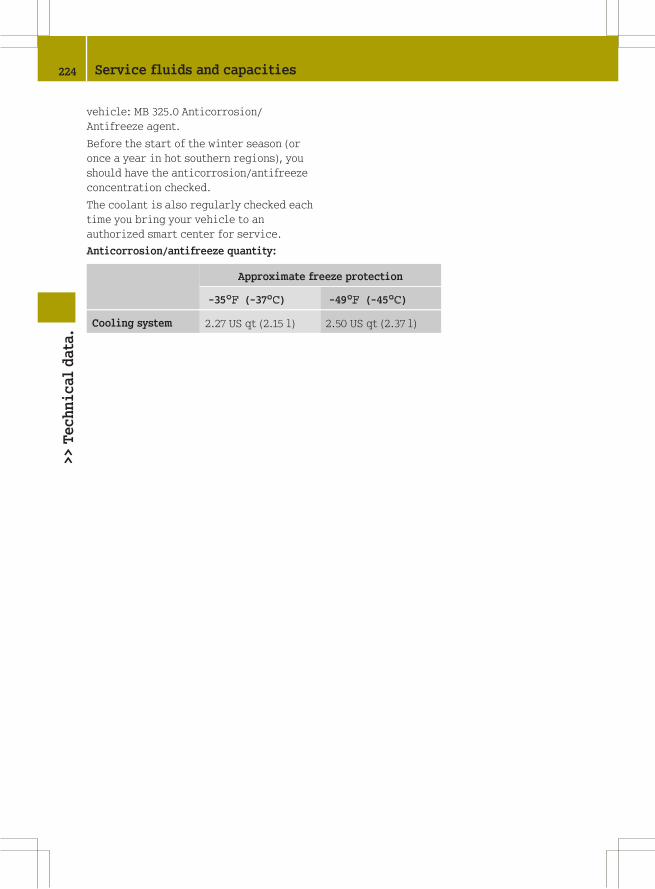
vehicle: MB 325.0 Anticorrosion/
Antifreeze agent.
Before the start of the winter season (or
once a year in hot southern regions), you
should have the anticorrosion/antifreeze
concentration checked.
The coolant is also regularly checked each
time you bring your vehicle to an
authorized smart center for service.
Anticorrosion/antifreeze quantity:
Approximate freeze protection
-35¦ (-37¥) -49¦ (-45¥)
Cooling system 2.27 US qt (2.15 l) 2.50 US qt (2.37 l)
224 Service fluids and capacities>>Technicaldata.