2013 san francisco building code...
TRANSCRIPT

2013 SAN FRANCISCO BUILDING CODE
1/1/2014 Page 100-1
AB-100
ADMINISTRATIVE BULLETIN
NO. AB-100 :
DATE : July 12, 2012 (Updated 01/01/014 for code references)
SUBJECT : Permit Review and Operation
TITLE : Post-Earthquake Repair and Retrofit Requirements for One- and Two-Family Units
PURPOSE : The purpose of this Bulletin is to establish policy for interpreting the San Francisco BuildingCode regarding post-earthquake damage retrofit triggers for one- and two-family dwellings ofwood-frame construction and to detail the scope and criteria for such triggered retrofits. TheBulletin also provides guidance on the scope of required building repair if retrofits are nottriggered.
REFERENCES : 2013 San Francisco Building Code- Section 3401.8, Lateral force design requirements for existing buildings- Section 3402, Definition of Disproportionate Damage [pending code revision]- Section 3402, Definition of Substantial Structural Damage- Section 3405, Repairs
2013 California Historical Building Code, C.C.R. Title Part 8
2012 International Existing Building Code, Appendix Chapter A4, or 2009 InternationalExisting Building Code, Appendix Chapter A4 with NCSEA/SEAOC amendments
ASCE/SEI Standard 31, Seismic Evaluation of Existing Buildings
ASCE/SEI Standard 41, Seismic Rehabilitation of Existing Buildings, with Supplement 1California Health and Safety Code, Section 17920.3
CAPSS Report, Here Today Here Tomorrow: The Road to Earthquake Resilience in SanFrancisco, Post-Earthquake Repair and Retrofit Requirements (ATC-52-4 Report),http://www.sfcapss.org/PDFs/PostQuakeRepair.pdf
CUREE EDA-2: General Guidelines for the Assessment and Repair of Earthquake Damage inResidential Woodframe Buildings, (CUREE, 2010)
FEMA 306: Evaluation of Earthquake Damaged Concrete and Masonry Wall Buildings: BasicProcedures Manual (FEMA, 1999)
DISCUSSION : San Francisco Building Code, Section 3405.2 triggers seismic evaluation, and possibly retrofitof buildings, when earthquake-related damage reaches the level of “substantial structuraldamage to vertical elements of the lateral-force-resisting system.” Substantial structural damageis defined in San Francisco Building Code, Section 3402 as, in essence, a loss of lateral capacityof 20 percent or more in any horizontal direction. The code does not give specific rules foridentifying a 20-percent capacity loss nor guidance as to how to calculate capacity loss, soimplementation of these code provisions relies on interpretation by the Department of BuildingInspection. This Bulletin presents the Department’s interpretation of a 20-percent lateralcapacity loss based on visual indicators of such damage, and details the evaluation procedure

2013 SAN FRANCISCO BUILDING CODE
1/1/2014Page 100-2
AB-100
and retrofit scope for buildings that exhibit earthquake-induced substantial structural damage.The Bulletin also provides guidance on the scope of required repair of building components orassemblies if such retrofits are not triggered.
In addition to substantial structural damage, San Francisco Building Code, Section 3405.4 triggers structural evaluationand possibly retrofit when earthquake-related damage reaches the level of disproportionate damage, which is definedin San Francisco Building Code, Section 3402 as, in essence, a lateral capacity loss of 10 percent or more in anearthquake of limited intensity. This Bulletin presents the Department of Building Inspection’s interpretation of a 10percent capacity loss based on visual indicators of such damage and provides evaluation procedures and retrofit scopefor buildings with such earthquake induced disproportionate damage. [provisional, pending San Francisco Building Codeadoption of provisions for Disproportionate Damage.]
Residential buildings that incur substantial structural damage or disproportionate damage as detailed in this Bulletinare considered to be “substandard” per California Health and Safety Code Section 17920.3(b) Structural hazards and(o) Inadequate structural resistance to horizontal forces.
APPLICABILITY
A building is eligible to apply the interpretations and provisions of this Bulletin if all of the following criteria are met:
A. The building includes at least one story in which the seismic force-resisting system consists of a wood light-framesystem in at least one direction, and
B. The building has only wood floor and roof diaphragms, and
C. The building contains a residential occupancy group R-3 as defined in San Francisco Building Code, Section 310.At the discretion of the Department of Building Inspection, a building in this group may be evaluated and repaired orretrofitted using the criteria for a residential building with three or more units under AB-098 if the building is structurallyand architecturally similar to that group of buildings.
Buildings of other construction types and occupancies may also apply the provisions of this Bulletin on a case-by- casebasis when approved by the Department of Building Inspection. Other methods of determining capacity loss based onanalysis, testing, or other objective data may also be allowed at the discretion of the Department.
Qualified buildings may be permitted to be evaluated or retrofitted using the provisions in the California HistoricalBuilding Code provided that such provisions do not result in seismic performance that is less than the evaluation andretrofit engineering provisions detailed in this Bulletin.
EVALUATION PROCEDURES AND RETROFIT SCOPE
For the purpose of determining if a building has incurred substantial structural damage or disproportionate damage perSan Francisco Building Code, visual observation and classification of damage and severity may be used in lieu of acalculation of percentage loss of capacity. All determinations of substantial structural damage or disproportionatedamage, including visual observation and classification of damage and severity, shall be made by a licensed designprofessional, and evaluation shall be submitted in accordance with San Francisco Building Code, Section 3405.2.1. Fordamage not deemed to be either substantial structural damage or disproportionate damage, repairs shall restore thebuilding to its original strength or condition by methods acceptable to the Department of Building Inspection.
Buildings with Substantial Structural Damage
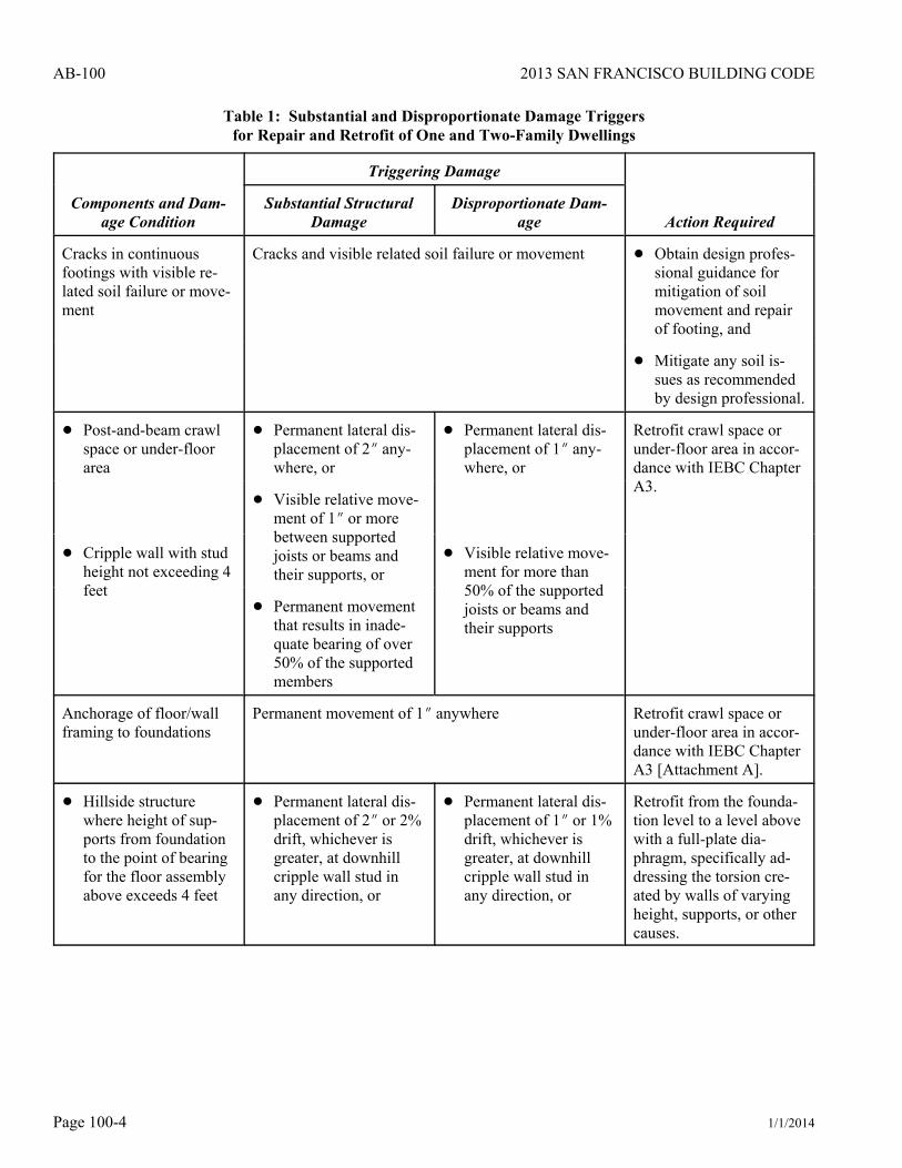
Earthquake-induced substantial structural damage to elements of lateral force-resisting system of a building shall bedeemed to exist when any of the components and conditions is observed to reach the severity of “triggering damage”given in Table 1. For buildings with such substantial structural damage, evaluation and retrofit, where required, shallproceed in accordance with the “Action Required” column shown in Table 1 and the “Further Evaluation and RetrofitEngineering Criteria” section.

2013 SAN FRANCISCO BUILDING CODE
1/1/2014 Page 100-3
AB-100
Buildings with Disproportionate Damage
Disproportionate damage to elements of the lateral force-resisting system of a building shall be deemed to exist whenany of the components and conditions is observed to reach the severity of “triggering damage” given in Table 1. Forbuildings with such disproportionate damage, evaluation and retrofit, where required, shall proceed in accordance withthe “Action Required” column shown in Table 1 and the “Further Evaluation and Retrofit Engineering Criteria” section.
Table 1: Substantial and Disproportionate Damage Triggersfor Repair and Retrofit of One and Two-Family Dwellings
Components and Dam-age Condition
Triggering Damage
Action RequiredSubstantial Structural
DamageDisproportionate Dam-
age
Stone or masonry veneer,incidental URM wall(non-chimney)
! Appearance similar to“Heavy Damage” asdescribed in Section7.5 of FEMA 306 [At-tachment B], or
! Appearance similar to“Moderate Damage”as described in Section7.5 of FEMA 306 [At-tachment B], or
Remove and replace dam-aged elements.
! Failure of anchorage tobacking in over 20%of the wall area
! Visible failure of an-chorage to backinganywhere
! URM foundation piers ! “Moderate Damage” as described in Section 7.5 ofFEMA 306 [Attachment B], or
Retrofit crawl space orunder-floor area.
! Visible relative movement of supported joist orbeams on support of 1O or more, or! Continuous footings
with crawl space orunder-floor area ! Permanent movement that results in inadequate
bearing of supported member
Cracks in continuousfootings without visiblerelated soil failure ormovement
Crack width of less than 0.25O No retrofit required. Re-pair to original strength inaccordance with Section4A.3 of CUREE EDA-2.
Crack width or offset of greater than 0.25O No retrofit required. Ob-tain design professionalguidance for repair.
2013 SAN FRANCISCO BUILDING CODE
1/1/2014Page 100-4
AB-100
Table 1: Substantial and Disproportionate Damage Triggersfor Repair and Retrofit of One and Two-Family Dwellings
Components and Dam-age Condition
Triggering Damage
Action RequiredSubstantial Structural
DamageDisproportionate Dam-
age
Cracks in continuousfootings with visible re-lated soil failure or move-ment
Cracks and visible related soil failure or movement ! Obtain design profes-sional guidance formitigation of soilmovement and repairof footing, and
! Mitigate any soil is-sues as recommendedby design professional.
! Post-and-beam crawlspace or under-floorarea
! Permanent lateral dis-placement of 2O any-where, or
! Permanent lateral dis-placement of 1O any-where, or
Retrofit crawl space orunder-floor area in accor-dance with IEBC ChapterA3.
! Visible relative move-ment of 1O or morebetween supportedjoists or beams andtheir supports, or
! Cripple wall with studheight not exceeding 4feet
! Visible relative move-ment for more than50% of the supportedjoists or beams andtheir supports
! Permanent movementthat results in inade-quate bearing of over50% of the supportedmembers
Anchorage of floor/wallframing to foundations
Permanent movement of 1O anywhere Retrofit crawl space orunder-floor area in accor-dance with IEBC ChapterA3 [Attachment A].
! Hillside structurewhere height of sup-ports from foundationto the point of bearingfor the floor assemblyabove exceeds 4 feet
! Permanent lateral dis-placement of 2O or 2%drift, whichever isgreater, at downhillcripple wall stud inany direction, or
! Permanent lateral dis-placement of 1O or 1%drift, whichever isgreater, at downhillcripple wall stud inany direction, or
Retrofit from the founda-tion level to a level abovewith a full-plate dia-phragm, specifically ad-dressing the torsion cre-ated by walls of varyingheight, supports, or othercauses.

2013 SAN FRANCISCO BUILDING CODE
1/1/2014 Page 100-5
AB-100
Table 1: Substantial and Disproportionate Damage Triggersfor Repair and Retrofit of One and Two-Family Dwellings
Components and Dam-age Condition
Triggering Damage
Action RequiredSubstantial Structural
DamageDisproportionate Dam-
age
! Cripple wall with studheight exceeding 4 feet
! Failure of connectionsin downhill supports ifpost-and-beam bracedframe or momentframe, or
! Signs of movementthat could lead to fail-ure of the downhillsupports, or
! Separation of uphillframing from founda-tion support or indica-tion of relative move-ment during shaking of1O or more in the di-rection parallel to theslope
! Visible relative move-ment of the uphill sup-port in the directionparallel to the slope
Weak Story: when anystory has less than 80% ofthe strength of the storyabove in either direction
! Permanent lateral displacement of 2O or more, or Retrofit soft story and anysupport system below.
! Indication of any lateral movement in story of 4O ormore during shaking in any direction
Stories other than weakstories
! Permanent lateral displacement of 2O or more any-where in any direction, or
! Retrofit from damagedstory down to thefoundation, and
! Permanent lateral displacement of 1O anywhere iftorsional displacement is observed, or
! Repair walls not partof the designated lat-eral force-resistingsystem in accordancewith Section 5.8 ofCUREE EDA-2.
! Indications of excessive response such as severecracking of brittle walls nail fracture or pullout inwood, multiple jammed doors, and/or broken win-dows
Connection between twoparts of a structure includ-ing wings, split levels,porches, and beam to postconnections
! Permanent separation or sliding at joint of 1O ormore, or
Provide structural separa-tion with independentgravity support for eachstructure or a seismic tiethat will transfer 20% ofthe weight of the lighterportion across the joint.
! Permanent movement that results in inadequatebearing of a supported member
2013 SAN FRANCISCO BUILDING CODE
1/1/2014Page 100-6
AB-100
Table 1: Substantial and Disproportionate Damage Triggersfor Repair and Retrofit of One and Two-Family Dwellings
Components and Dam-age Condition
Triggering Damage
Action RequiredSubstantial Structural
DamageDisproportionate Dam-
age
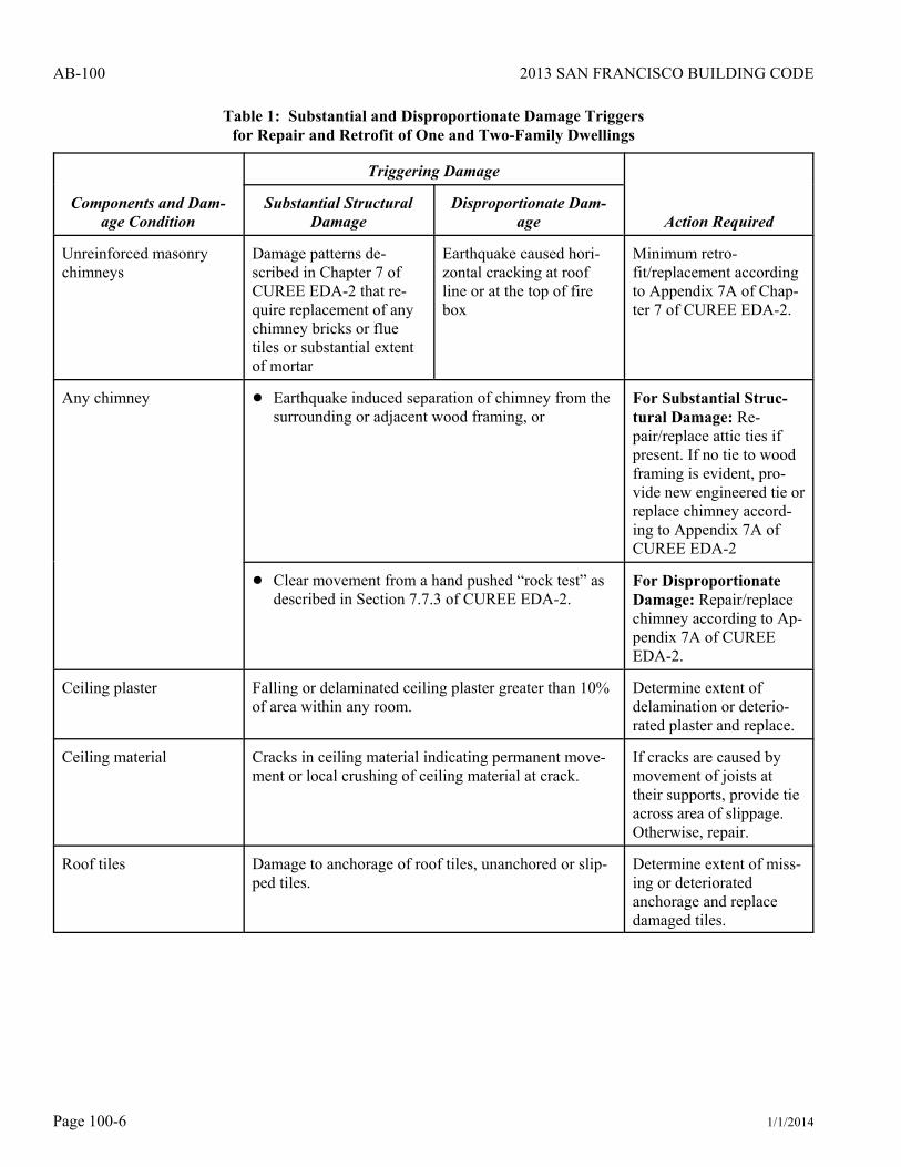
Unreinforced masonrychimneys
Damage patterns de-scribed in Chapter 7 ofCUREE EDA-2 that re-quire replacement of anychimney bricks or fluetiles or substantial extentof mortar
Earthquake caused hori-zontal cracking at roofline or at the top of firebox
Minimum retro-fit/replacement accordingto Appendix 7A of Chap-ter 7 of CUREE EDA-2.
Any chimney ! Earthquake induced separation of chimney from thesurrounding or adjacent wood framing, or
For Substantial Struc-tural Damage: Re-pair/replace attic ties ifpresent. If no tie to woodframing is evident, pro-vide new engineered tie orreplace chimney accord-ing to Appendix 7A ofCUREE EDA-2
! Clear movement from a hand pushed “rock test” asdescribed in Section 7.7.3 of CUREE EDA-2.
For DisproportionateDamage: Repair/replacechimney according to Ap-pendix 7A of CUREEEDA-2.
Ceiling plaster Falling or delaminated ceiling plaster greater than 10%of area within any room.
Determine extent ofdelamination or deterio-rated plaster and replace.
Ceiling material Cracks in ceiling material indicating permanent move-ment or local crushing of ceiling material at crack.
If cracks are caused bymovement of joists attheir supports, provide tieacross area of slippage.Otherwise, repair.
Roof tiles Damage to anchorage of roof tiles, unanchored or slip-ped tiles.
Determine extent of miss-ing or deterioratedanchorage and replacedamaged tiles.
2013 SAN FRANCISCO BUILDING CODE
1/1/2014 Page 100-7
AB-100
FURTHER EVALUATION AND RETROFIT ENGINEERING CRITERIA:
If, after an evaluation per San Francisco Building Code, Section 3405.2, the pre-earthquake building is determined tosatisfy the criteria, then the building need not be retrofitted, but shall be restored to its pre-earthquake capacity. Whenretrofit is triggered by earthquake damage at any level, the engineering criteria for retrofit shall be permitted to useearthquake loads that are 75 percent of those prescribed by the San Francisco Building Code for new construction, inaccordance with San Francisco Building Code, Section 3405.2.
Alternatively, any of the following codes, standards, or guidelines may be used as alternative evaluation or retrofitcriteria for qualifying buildings:
A. Meets the requirements of ASCE 31-03 for the Life Safety Performance Level, or
B. Meets the requirements of ASCE 41-06 for the Life Safety Performance Level (S-3) in a BSE-1 earthquake hazardlevel, or
C. Meets the requirements of 2012 IEBC Appendix Chapter A4 or 2009 IEBC Appendix Chapter A4 withNCSEA/SEAOC amendments, or
D. Meets the 2010 San Francisco Building Code, Sections 3415 3420.
Signed:
Tom C. Hui, S.E. 7/2/2012Acting DirectorDepartment of Building Inspection
Approved by the Building Inspection Commission on 6/20/2012
Attachment A: Excerpt from 2012 International Code for Existing Buildings, Appendix Chapters A3 & A4Attachment B: Excerpt from FEMA 306: Evaluation of Earthquake Damaged Concrete and Masonry Wall Buildings:
Basic Procedures Manual, Chapter 7, Section 5Attachment C: Excerpts from CUREE Publication No. EDA-02: General Guidelines for the Assessment and Repair of
Earthquake Damage in Residential Woodframe Buildings
2013 SAN FRANCISCO BUILDING CODE
1/1/2014Page 100-8
AB-100
ATTACHMENT A
2012 INTERNATIONAL CODE FOR EXISTING BUILDINGS, Appendix Chapters A3 & A4
Chapter A3 Prescriptive Provisions for Seismic Strengthening of Cripple Walls and Sill Plate Anchorage of LightWood-Frame Residential Buildings
SECTION A301 GENERAL
A301.1 Purpose.
The provisions of this chapter are intended to promote public safety and welfare by reducing the risk of earthquake-induced damage to existing wood-frame residential buildings. The requirements contained in this chapter are prescriptiveminimum standards intended to improve the seismic performance of residential buildings; however, they will notnecessarily prevent earthquake damage.
This chapter sets standards for strengthening that may be approved by the code official without requiring plans orcalculations prepared by a registered design professional. The provisions of this chapter are not intended to prevent theuse of any material or method of construction not prescribed herein. The code official may require that constructiondocuments for strengthening using alternative materials or methods be prepared by a registered design professional.
A301.2 Scope.
The provisions of this chapter apply to residential buildings of light-frame wood construction containing one or moreof the structural weaknesses specified in Section A303.
Exception: The provisions of this chapter do not apply to the buildings, or elements thereof, listed below. Thesebuildings or elements require analysis by a registered design professional in accordance with Section A301.3 todetermine appropriate strengthening:
1. Group R-1, R-2 or R-4 occupancies with more than four dwelling units.
2. Buildings with a lateral force-resisting system using poles or columns embedded in the ground.
3. Cripple walls that exceed 4 feet (1219 mm) in height.
4. Buildings exceeding three stories in height and any three-story building with cripple wall studs exceeding 14inches (356 mm) in height.
5. Buildings where the code official determines that conditions exist that are beyond the scope of the prescriptiverequirements of this chapter.
6. Buildings or portions thereof constructed on concrete slabs on grade.
A301.3 Alternative design procedures.
The details and prescriptive provisions herein are not intended to be the only acceptable strengthening methodspermitted. Alternative details and methods may be used where designed by a registered design professional and approvedby the code official. Approval of alternatives shall be based on a demonstration that the method or material used is atleast equivalent in terms of strength, deflection and capacity to that provided by the prescriptive methods and materials.
Where analysis by a registered design professional is required, such analysis shall be in accordance with all requirementsof the building code, except that the seismic forces may be taken as 75 percent of those specified in the building code.

2013 SAN FRANCISCO BUILDING CODE
1/1/2014 Page 100-9
AB-100
SECTION A302 DEFINITIONS
For the purpose of this chapter, in addition to the applicable definitions in the building code, certain additional terms aredefined as follows:
COMPOSITE PANEL. A wood structural panel product composed of a combination of wood veneer and wood- basedmaterial, and bonded with waterproof adhesive.
CRIPPLE WALL. A wood-frame stud wall extending from the top of the foundation to the underside of the lowest floorframing.
EXPANSION ANCHOR. An approved post-installed anchor, inserted into a pre-drilled hole in existing concrete ormasonry, that transfers loads to or from the concrete or masonry by direct bearing or friction or both.
ORIENTED STRAND BOARD (OSB). A mat-formed wood structural panel product composed of thin rectangular woodstrands or wafers arranged in oriented layers and bonded with waterproof adhesive.
PERIMETER FOUNDATION. A foundation system that is located under the exterior walls of a building.
PLYWOOD. A wood structural panel product composed of sheets of wood veneer bonded together with the grain ofadjacent layers oriented at right angles to one another.
SNUG-TIGHT. As tight as an individual can torque a nut on a bolt by hand, using a wrench with a 10-inch-long (254mm) handle, and the point at which the full surface of the plate washer is contacting the wood member and slightlyindenting the wood surface.
WAFERBOARD. A mat-formed wood structural panel product composed of thin rectangular wood wafers arranged inrandom layers and bonded with waterproof adhesive.
WOOD STRUCTURAL PANEL. A structural panel product composed primarily of wood and meeting the requirementsof United States Voluntary Product Standard PS 1 and United States Voluntary Product Standard PS 2. Wood structuralpanels include all-veneer plywood, composite panels containing a combination of veneer and wood-based material, andmat-formed panels such as oriented strand board and waferboard.
SECTION A303 STRUCTURAL WEAKNESSES
A303.1 General.
For the purpose of this chapter, structural weaknesses shall be as specified below.
1. Sill plates or floor framing that are supported directly on the ground without a foundation system that conformsto the building code.
2. A perimeter foundation system that is constructed only of wood posts supported on isolated pad footings.
3. Perimeter foundation systems that are not continuous.
Exceptions:
1. Existing single-story exterior walls not exceeding 10 feet (3048 mm) in length, forming an extension of floorarea beyond the line of an existing continuous perimeter foundation.
2. Porches, storage rooms and similar spaces not containing fuel-burning appliances.
4. A perimeter foundation system that is constructed of unreinforced masonry or stone.
5. Sill plates that are not connected to the foundation or that are connected with less than what is required by thebuilding code.
Exception: Where approved by the code official, connections of a sill plate to the foundation made with otherthan sill bolts may be accepted if the capacity of the connection is equivalent to that required by the building code.

2013 SAN FRANCISCO BUILDING CODE
1/1/2014Page 100-10
AB-100
6. Cripple walls that are not braced in accordance with the requirements of Section A304.4 and Table A3-A, orcripple walls not braced with diagonal sheathing or wood structural panels in accordance with the building code.
SECTION A304 STRENGTHENING REQUIREMENTS
A304.1 General.
A304.1.1 Scope.
The structural weaknesses noted in Section A303 shall be strengthened in accordance with the requirements of thissection. Strengthening work may include both new construction and alteration of existing construction. Except asprovided herein, all strengthening work and materials shall comply with the applicable provisions of the building code.
A304.1.2 Condition of existing wood materials.
All existing wood materials that will be a part of the strengthening work (sills, studs, sheathing, etc.) shall be in a soundcondition and free from defects that substantially reduce the capacity of the member. Any wood material found to containfungus infection shall be removed and replaced with new material. Any wood material found to be infested with insectsor to have been infested with insects shall be strengthened or replaced with new materials to provide a net dimensionof sound wood at least equal to its undamaged original dimension.
A304.1.3 Floor joists not parallel to foundations.
Floor joists framed perpendicular or at an angle to perimeter foundations shall be restrained either by an existing nominal2-inch-wide (51 mm) continuous rim joist or by a nominal 2-inch-wide (51 mm) full-depth block between alternate joistsin one-and two-story buildings, and between each joist in three-story buildings. Existing blocking for multistorybuildings must occur at each joist space above a braced cripple wall panel.
Existing connections at the top and bottom edges of an existing rim joist or blocking need not be verified in one-storybuildings. In multistory buildings, the existing top edge connection need not be verified; however, the bottom edgeconnection to either the foundation sill plate or the top plate of a cripple wall shall be verified. The minimum existingbottom edge connection shall consist of 8d toenails spaced 6 inches (152 mm) apart for a continuous rim joist, or three8d toenails per block. When this minimum bottom edge-connection is not present or cannot be verified, a supplementalconnection installed as shown in Figure A3-8A or A3-8C shall be provided.
Where an existing continuous rim joist or the minimum existing blocking does not occur, new 3/4-inch (19 mm) or23/32-inch (18 mm) wood structural panel blocking installed tightly between floor joists and nailed as shown in FigureA3-9 shall be provided at the inside face of the cripple wall. In lieu of wood structural panel blocking, tight fitting, full-depth 2-inch (51 mm) blocking may be used. New blocking may be omitted where it will interfere with vents orplumbing that penetrates the wall.
A304.1.4 Floor joists parallel to foundations.
Where existing floor joists are parallel to the perimeter foundations, the end joist shall be located over the foundationand, except for required ventilation openings, shall be continuous and in continuous contact with the foundation sill plateor the top plate of the cripple wall. Existing connections at the top and bottom edges of the end joist need not be verifiedin one-story buildings. In multistory buildings, the existing top edge connection of the end joist need not be verified;however, the bottom edge connection to either the foundation sill plate or the top plate of a cripple wall shall be verified.The minimum bottom edge connection shall be 8d toenails spaced 6 inches (152 mm) apart. If this minimum bottom edgeconnection is not present or cannot be verified, a supplemental connection installed as shown in Figure A3-8B, A3-8Cor A3-9 shall be provided.
A304.2 Foundations.
A304.2.1 New perimeter foundations.
New perimeter foundations shall be provided for structures with the structural weaknesses noted in Items 1 and 2 ofSection A303. Soil investigations or geotechnical studies are not required for this work unless the building is locatedin a special study zone as designated by the code official or other authority having jurisdiction.
2013 SAN FRANCISCO BUILDING CODE
1/1/2014 Page 100-11
AB-100
A304.3 Foundation sill plate anchorage.
A304.3.1 Existing perimeter foundations.
Where the building has an existing continuous perimeter foundation, all perimeter wall sill plates shall be anchored tothe foundation with adhesive anchors or expansion anchors in accordance with Table A3-A.
Anchors shall be installed in accordance with Figure A3-3, with the plate washer installed between the nut and the sillplate. The nut shall be tightened to a snug-tight condition after curing is complete for adhesive anchors and afterexpansion wedge engagement for expansion anchors. All anchors shall be installed in accordance with manufacturer’srecommendations. Where existing conditions prevent anchor installations through the sill plate, this connection may bemade in accordance with Figure A3-4A, A3-4B, or A3-4C. The spacing of these alternate connections shall comply withthe maximum spacing requirements of Table A3-A. Expansion anchors shall not be used where the installation causessurface cracking of the foundation wall at the locations of the bolt.
A304.4 Cripple wall bracing.
A304.4.1 General.
Exterior cripple walls not exceeding 4 feet (1219 mm) in height shall be permitted to be specified by the prescriptivebracing method in Section A304.4. Cripple walls over 4 feet (1219 mm) in height require analysis by a registered designprofessional in accordance with Section A301.3.
A304.5 Quality control.
All work shall be subject to inspection by the code official including, but not limited to:
1. Placement and installation of new adhesive or expansion anchors installed in existing foundations. Specialinspection is not required for adhesive anchors installed in existing foundations regulated by the prescriptive provisionsof this chapter.
2. Installation and nailing of new cripple wall bracing.
3. Any work may be subject to special inspection when required by the code official in accordance with the buildingcode.
Chapter A4 Earthquake Risk Reduction in Wood-Frame Residential Buildings with Soft, Weak or Open FrontWalls
SECTION A401 GENERAL
A401.1 Purpose.
The purpose of this chapter is to promote public welfare and safety by reducing the risk of death or injury that may resultfrom the effects of earthquakes on existing wood-frame, multi-unit residential buildings. The ground motions of pastearthquakes have caused the loss of human life, personal injury and property damage in these types of buildings. Thischapter creates minimum standards to strengthen the more vulnerable portions of these structures. When fully followed,these minimum standards will improve the performance of these buildings but will not necessarily prevent all earthquake-related damage.
A401.2 Scope.
The provisions of this chapter shall apply to all existing Occupancy Group R-1 and R-2 buildings of wood constructionor portions thereof where the structure has a soft, weak, or open-front wall line, and there exists one or more storiesabove.

2013 SAN FRANCISCO BUILDING CODE
1/1/2014Page 100-12
AB-100
SECTION A402 DEFINITIONS
Notwithstanding the applicable definitions, symbols and notations in the building code, the following definitions shallapply for the purposes of this chapter:
GROUND FLOOR. Any floor whose elevation is immediately accessible from an adjacent grade by vehicles orpedestrians. The ground floor portion of the structure does not include any floor that is completely below adjacent grades.
NONCONFORMING STRUCTURAL MATERIALS. Wall bracing materials other than wood structural panels ordiagonal sheathing.
OPEN-FRONT WALL LINE. An exterior wall line, without vertical elements of the lateral force-resisting system, thatrequires tributary seismic forces to be resisted by diaphragm rotation or excessive cantilever beyond parallel lines ofshear walls. Diaphragms that cantilever more than 25 percent of the distance between lines of lateral force- resistingelements from which the diaphragm cantilevers shall be considered excessive. Exterior exit balconies of 6 feet (1829mm) or less in width shall not be considered excessive cantilevers.
RETROFIT. An improvement of the lateral force-resisting system by alteration of existing structural elements oraddition of new structural elements.
SOFT WALL LINE. A wall line whose lateral stiffness is less than that required by story drift limitations or deformationcompatibility requirements of this chapter. In lieu of analysis, a soft wall line may be defined as a wall line in a storywhere the story stiffness is less than 70 percent of the story above for the direction under consideration.
STORY. A story as defined by the building code, including any basement or underfloor space of a building with cripplewalls exceeding 4 feet (1219 mm) in height.
STORY STRENGTH. The total strength of all seismic-resisting elements sharing the same story shear in the directionunder consideration.
WALL LINE. Any length of wall along a principal axis of the building used to provide resistance to lateral loads. Parallelwall lines separated by less than 4 feet (1219 mm) shall be considered one wall line for the distribution of loads.
WEAK WALL LINE. A wall line in a story where the story strength is less than 80 percent of the story above in thedirection under consideration.
SECTION A403 ANALYSIS AND DESIGN
A403.1 General.
All modifications required by the provisions in this chapter shall be designed in accordance with the InternationalBuilding Code provisions for new construction, except as modified by this chapter.
Exception: Buildings for which the prescriptive measures provided in Section A404 apply and are used.
No alteration of the existing lateral force-resisting system or vertical load-carrying system shall reduce the strength orstiffness of the existing structure, unless the altered structure would remain in conformance to the building code and thischapter.
A403.2 Scope of analysis.
This chapter requires the alteration, repair, replacement or addition of structural elements and their connections to meetthe strength and stiffness requirements herein. The lateral-load-path analysis shall include the resisting elements andconnections from the wood diaphragm immediately above any soft, weak or open-front wall lines to the foundation soilinterface or to the uppermost story of a podium structure comprised of steel, masonry, or concrete structural systems thatsupports the upper, wood-framed structure. Stories above the uppermost story with a soft, weak, or open-front wall lineshall be considered in the analysis but need not be modified. The lateral-load-path analysis for added structural elementsshall also include evaluation of the allowable soil-bearing and lateral pressures in accordance with the building code.Where any portion of a building within the scope of this chapter is constructed on or into a slope steeper than one unit

2013 SAN FRANCISCO BUILDING CODE
1/1/2014 Page 100-13
AB-100
vertical in three units horizontal (33-percent slope), the lateral force-resisting system at and below the base leveldiaphragm shall be analyzed for the effects of concentrated lateral forces at the base caused by this hillside condition.
Exception: When an open-front, weak or soft wall line exists because of parking at the ground floor of a two- storybuilding and the parking area is less than 20 percent of the ground floor area, then only the wall lines in the open, weakor soft directions of the enclosed parking area need comply with the provisions of this chapter.
A403.3 Design base shear and design parameters.
The design base shear in a given direction shall be permitted to be 75 percent of the value required for similar newconstruction in accordance with the building code. The value of R used in the design of the strengthening of any storyshall not exceed the lowest value of R used in the same direction at any story above. The system overstrength factor, 0,and the deflection amplification factor, Cd, shall not be less than the largest respective value corresponding to the Rfactor being used in the direction under consideration.
Exceptions:
1. For structures assigned to Seismic Design Category B, values of R, 0 and Cd shall be permitted to be based onthe seismic force-resisting system being used to achieve the required strengthening.
2. For structures assigned to Seismic Design Category C or D, values of R, 0 and Cd shall be permitted to be basedon the seismic force-resisting system being used to achieve the required strengthening, provided that when thestrengthening is complete, the strengthened structure will not have an extreme weak story irregularity defined as Type5b in ASCE 7 Table 12.3-2.
3. For structures assigned to Seismic Design Category E, values of R, 0 and Cd shall be permitted to be based on theseismic force-resisting system being used to achieve the required strengthening, provided that when the strengtheningis complete, the strengthened structure will not have an extreme soft story, a weak story, or an extreme weak storyirregularity defined, respectively, as Types 1b, 5a and 5b in ASCE 7 Table 12.3-2.
A403.4 Story drift limitations.
The calculated story drift for each retrofitted story shall not exceed the allowable deformation compatible with all verticalload-resisting elements and 0.025 times the story height. The calculated story drift shall not be reduced by the effectsof horizontal diaphragm stiffness but shall be increased when these effects produce rotation. Drift calculations shall bein accordance with the building code.
A403.5 P effects.
The requirements of the building code shall apply, except as modified herein. All structural framing elements and theirconnections not required by design to be part of the lateral force-resisting system shall be designed and/or detailed tobe adequate to maintain support of design dead plus live loads when subjected to the expected deformations caused byseismic forces. The stress analysis of cantilever columns shall use a buckling factor of 2.1 for the direction normal tothe axis of the beam.
A403.6 Ties and continuity.
All parts of the structure included in the scope of Section A403.2 shall be interconnected as required by the buildingcode.
A403.7 Collector elements.
Collector elements shall be provided that can transfer the seismic forces originating in other portions of the building tothe elements within the scope of Section A403.2 that provide resistance to those forces.
A403.8 Horizontal diaphragms.
The strength of an existing horizontal diaphragm sheathed with wood structural panels or diagonal sheathing need notbe investigated unless the diaphragm is required to transfer lateral forces from vertical elements of the seismic force-resisting system above the diaphragm to elements below the diaphragm because of an offset in placement of the elements.

2013 SAN FRANCISCO BUILDING CODE
1/1/2014Page 100-14
AB-100
Wood diaphragms with stories above shall not be allowed to transmit lateral forces by rotation or cantilever except asallowed by the building code; however, rotational effects shall be accounted for when unsymmetric wall stiffnessincreases shear demands.
Exception: Diaphragms that cantilever 25 percent or less of the distance between lines of lateral load-resistingelements from which the diaphragm cantilevers may transmit their shears by cantilever, provided that rotational effectson shear walls parallel and perpendicular to the load are taken into account.
A403.9 Wood-framed shear walls.
Wood-framed shear walls shall have strength and stiffness sufficient to resist the seismic loads and shall conform to therequirements of this section.
SECTION A404 PRESCRIPTIVE MEASURES FOR WEAK STORY
A404.1 Limitation.
These prescriptive measures shall apply only to two-story buildings and only when deemed appropriate by the codeofficial. These prescriptive measures rely on rotation of the second floor diaphragm to distribute the seismic load betweenthe side and rear walls of the ground floor open area. In the absence of an existing floor diaphragm of wood structuralpanel or diagonal sheathing, a new wood structural panel diaphragm of minimum thickness of 3/4 inch (19 mm) and with10d common nails at 6 inches (152 mm) on center shall be applied.
A404.2 Minimum required retrofit.
A404.2.1 Anchor size and spacing.
The anchor size and spacing shall be a minimum of 3/4 inch (19 mm) in diameter at 32 inches (813 mm) on center.Where existing anchors are inadequate, supplemental or alternative approved connectors (such as new steel plates boltedto the side of the foundation and nailed to the sill) shall be used.
SECTION A405 MATERIALS OF CONSTRUCTION
A405.1 New materials.
New materials shall meet the requirements of the International Building Code, except where allowed by this chapter.
A405.2 Allowable foundation and lateral pressures.
The use of default values from the building code for continuous and isolated concrete spread footings shall be permitted.For soil that supports embedded vertical elements, Section A403.6 shall apply.
A405.3 Existing materials.
The physical condition, strengths, and stiffnesses of existing building materials shall be taken into account in anyanalysis required by this chapter. The verification of existing materials conditions and their conformance to theserequirements shall be made by physical observation, material testing or record drawings as determined by the registereddesign professional subject to the approval of the code official.
SECTION A406 INFORMATION REQUIRED TO BE ON THE PLANS
A406.1 General.
The plans shall show all information necessary for plan review and for construction and shall accurately reflect the resultsof the engineering investigation and design. The plans shall contain a note that states that this retrofit was designed incompliance with the criteria of this chapter.
A406.2 Existing construction.
The plans shall show existing diaphragm and shear wall sheathing and framing materials; fastener type and spacing;diaphragm and shear wall connections; continuity ties; and collector elements. The plans shall also show the portion ofthe existing materials that needs verification during construction.

2013 SAN FRANCISCO BUILDING CODE
1/1/2014 Page 100-15
AB-100
A406.3 New construction.
A406.3.1 Foundation plan elements.
The foundation plan shall include the size, type, location and spacing of all anchor bolts with the required depth ofembedment, edge and end distance; the location and size of all shear walls and all columns for braced frames or momentframes; referenced details for the connection of shear walls, braced frames or moment-resisting frames to their footing;and referenced sections for any grade beams and footings.
SECTION A407 QUALITY CONTROL
A407.1 Structural observation, testing and inspection.
Structural observation, in accordance with Section 1709 of the International Building Code, shall be required for allstructures in which seismic retrofit is being performed in accordance with this chapter. Structural observation shallinclude visual observation of work for conformance to the approved construction documents and confirmation of existingconditions assumed during design.
Structural testing and inspection for new construction materials shall be in accordance with the building code, exceptas modified by this chapter.

2013 SAN FRANCISCO BUILDING CODE
1/1/2014Page 100-16
AB-100
ATTACHMENT B
BASIC PROCEDURES MANUAL FEMA 306
Chapter 7.5 Unreinforced Masonry Component Guides
The following Component Damage Classification Guides contain details of the behavior modes for unreinforced masonrycomponents. Included are the distinguishing characteristics of the specific behavior mode, the description of damage atvarious levels of severity, and performance restoration measures. Information may not be included in the ComponentDamage Classification Guides for certain damage severity levels; in these instances, for the behavior mode underconsideration, it is not possible to make refined distinctions with regard to severity of damage. See also Section 3.5 forgeneral discussion of the use of the Component Guides and Section 4.4.3 for information on the modeling andacceptability criteria for components.
2013 SAN FRANCISCO BUILDING CODE
1/1/2014 Page 100-17
AB-100
COMPONENT DAMAGE System: URM
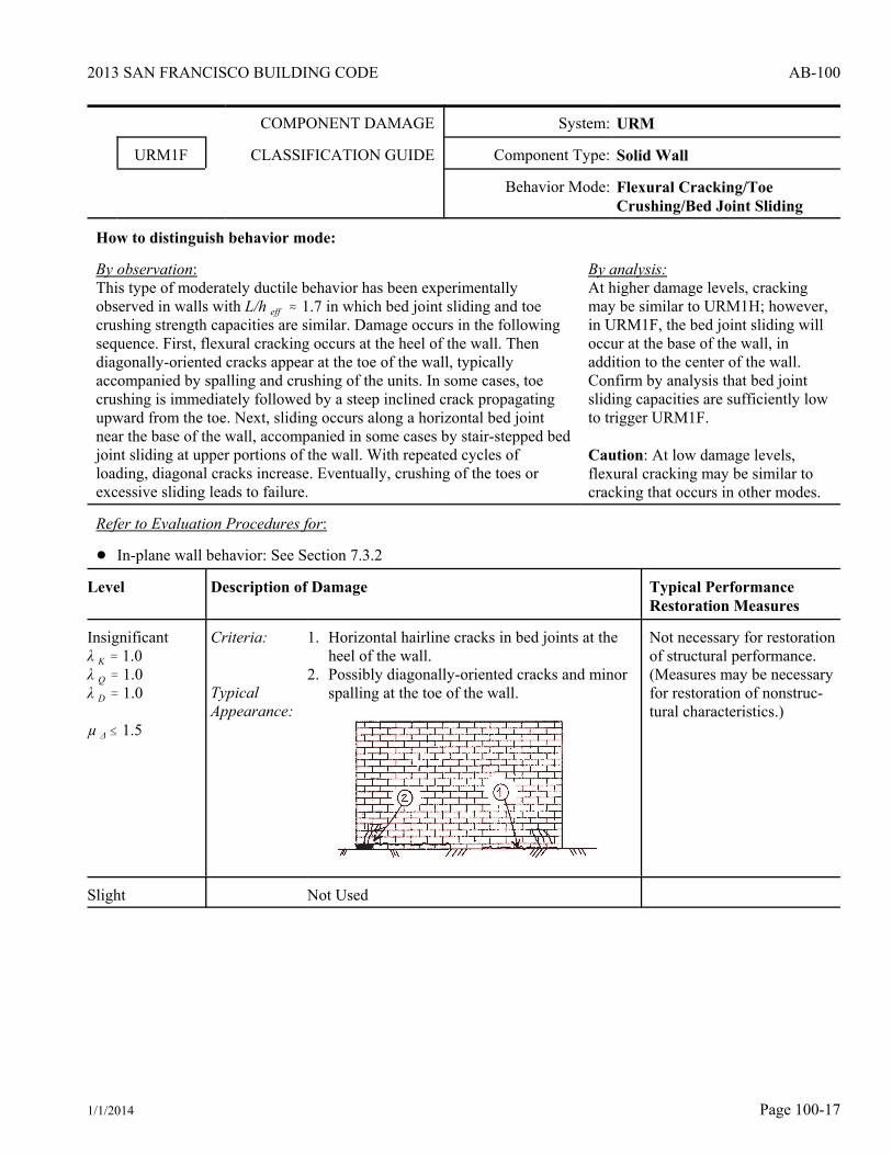
URM1F CLASSIFICATION GUIDE Component Type: Solid Wall
Behavior Mode: Flexural Cracking/ToeCrushing/Bed Joint Sliding
How to distinguish behavior mode:
By observation:This type of moderately ductile behavior has been experimentallyobserved in walls with L/h eff . 1.7 in which bed joint sliding and toecrushing strength capacities are similar. Damage occurs in the followingsequence. First, flexural cracking occurs at the heel of the wall. Thendiagonally-oriented cracks appear at the toe of the wall, typicallyaccompanied by spalling and crushing of the units. In some cases, toecrushing is immediately followed by a steep inclined crack propagatingupward from the toe. Next, sliding occurs along a horizontal bed jointnear the base of the wall, accompanied in some cases by stair-stepped bedjoint sliding at upper portions of the wall. With repeated cycles ofloading, diagonal cracks increase. Eventually, crushing of the toes orexcessive sliding leads to failure.
By analysis:At higher damage levels, crackingmay be similar to URM1H; however,in URM1F, the bed joint sliding willoccur at the base of the wall, inaddition to the center of the wall.Confirm by analysis that bed jointsliding capacities are sufficiently lowto trigger URM1F.
Caution: At low damage levels,flexural cracking may be similar tocracking that occurs in other modes.
Refer to Evaluation Procedures for:
! In-plane wall behavior: See Section 7.3.2
Level Description of Damage Typical PerformanceRestoration Measures
Insignificantλ K ' 1.0λ Q ' 1.0λ D ' 1.0
µ Δ # 1.5
Criteria:
Typical Appearance:
1. Horizontal hairline cracks in bed joints at theheel of the wall.
2. Possibly diagonally-oriented cracks and minorspalling at the toe of the wall.
Not necessary for restorationof structural performance.(Measures may be necessaryfor restoration of nonstruc-tural characteristics.)
Slight Not Used

2013 SAN FRANCISCO BUILDING CODE
1/1/2014Page 100-18
AB-100
COMPONENT DAMAGE CLASSIFICATION GUIDE continued URM
Level Description of Damage Typical PerformanceRestoration Measures
Moderate
λ K ' 0.9λ Q ' 0.6 1
λ D ' 0.9
1. As analternative,calculate as V bjs / V tc
Δ / h eff # 0.8%
Criteria:
TypicalAppearance:
1. Horizontal cracks/spalled mortar at bed joints ator near the base of the wall indicating that in-plane offset along the crack has occurred up toapproximately 1/4O.
2. Possibly diagonally-oriented cracks and spall-ing at the toe of the wall. Cracks extend upwardseveral courses.
3. Possibly diagonally-oriented cracks at upperportions of the wall which may be in the units.
! Replace/drypack damagedunits.
! Repoint spalled mortarand open head joints.
! Inject cracks and openhead joints.
! Install pins and drilleddowels in toe regions.
λ K* ' 1.0 1
λ Q* ' 1.0 1
λ D* ' 1.0 1
1. In some cases, groutinjection may actuallyincrease strength, butdecrease deformationcapacity, by changingbehavior from bed jointsliding to a less ductilebehavior mode (seeFEMA 307, Section4.1.3).
Heavy
λ K ' 0.8λ Q ' 0.6 1
λ D ' 0.9
1. As analternative,calculate as V bjs2 / V tc
Δ / h eff # 1.2%
Criteria:
TypicalAppearance:
1. Horizontal bed joint cracks near the base of thewall similar to Moderate, except width is up toapproximately 1/2O.
2. Possibly extensive diagonally-oriented cracksand spalling at the toe of the wall. Cracksextend upward several courses.
3. Possibly diagonally-oriented cracks up to 1/2Oat upper portions of the wall.
! Replace/drypack damagedunits.
! Repoint spalled mortarand open head joints.
! Inject cracks and openhead joints.
! Install pins and drilleddowels in toe regions.
λ K* ' 1.0 1
λ Q* ' 1.0 1
λ D* ' 1.0 1
1. In some cases, groutinjection may actuallyincrease strength, butdecrease deformationcapacity, by changingbehavior from bed jointsliding to a less ductilebehavior mode (seeFEMA 307, Section4.1.3).
2013 SAN FRANCISCO BUILDING CODE
1/1/2014 Page 100-19
AB-100
COMPONENT DAMAGE CLASSIFICATION GUIDE continued URM
Level Description of Damage Typical PerformanceRestoration Measures
Extreme Criteria:
TypicalIndications:
! Vertical load-carrying ability is threatened! Stair-stepped movement is so significant that
upper bricks have slid off their supportingbrick.
! Toes have begun to disintegrate.! Residual set is so significant that portions of
masonry at the edges of the pier have begun orare about to fall.
! Replacement orenhancement required.
COMPONENT DAMAGE System: URM
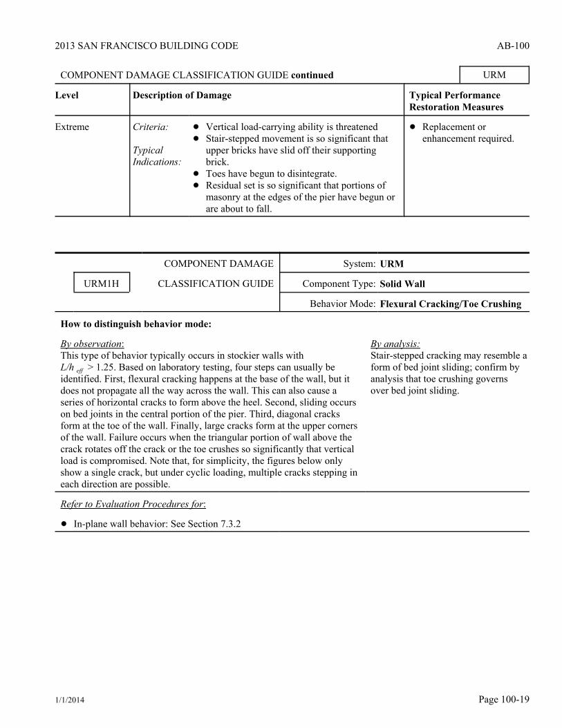
URM1H CLASSIFICATION GUIDE Component Type: Solid Wall
Behavior Mode: Flexural Cracking/Toe Crushing
How to distinguish behavior mode:
By observation:This type of behavior typically occurs in stockier walls withL/h eff > 1.25. Based on laboratory testing, four steps can usually beidentified. First, flexural cracking happens at the base of the wall, but itdoes not propagate all the way across the wall. This can also cause aseries of horizontal cracks to form above the heel. Second, sliding occurson bed joints in the central portion of the pier. Third, diagonal cracksform at the toe of the wall. Finally, large cracks form at the upper cornersof the wall. Failure occurs when the triangular portion of wall above thecrack rotates off the crack or the toe crushes so significantly that verticalload is compromised. Note that, for simplicity, the figures below onlyshow a single crack, but under cyclic loading, multiple cracks stepping ineach direction are possible.
By analysis:Stair-stepped cracking may resemble aform of bed joint sliding; confirm byanalysis that toe crushing governsover bed joint sliding.
Refer to Evaluation Procedures for:
! In-plane wall behavior: See Section 7.3.2
2013 SAN FRANCISCO BUILDING CODE
1/1/2014Page 100-20
AB-100
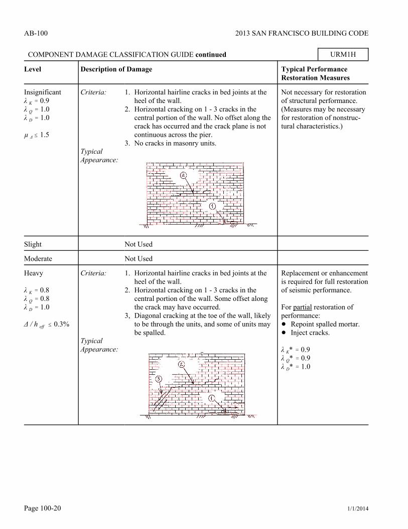
COMPONENT DAMAGE CLASSIFICATION GUIDE continued URM1H
Level Description of Damage Typical PerformanceRestoration Measures
Insignificantλ K ' 0.9λ Q ' 1.0λ D ' 1.0
µ Δ # 1.5
Criteria:
TypicalAppearance:
1. Horizontal hairline cracks in bed joints at theheel of the wall.
2. Horizontal cracking on 1 - 3 cracks in thecentral portion of the wall. No offset along thecrack has occurred and the crack plane is notcontinuous across the pier.
3. No cracks in masonry units.
Not necessary for restorationof structural performance.(Measures may be necessaryfor restoration of nonstruc-tural characteristics.)
Slight Not Used
Moderate Not Used
Heavy
λ K ' 0.8λ Q ' 0.8λ D ' 1.0
Δ / h eff # 0.3%
Criteria:
TypicalAppearance:
1. Horizontal hairline cracks in bed joints at theheel of the wall.
2. Horizontal cracking on 1 - 3 cracks in thecentral portion of the wall. Some offset alongthe crack may have occurred.
3, Diagonal cracking at the toe of the wall, likelyto be through the units, and some of units maybe spalled.
Replacement or enhancementis required for full restorationof seismic performance.
For partial restoration ofperformance:! Repoint spalled mortar.! Inject cracks.
λ K* ' 0.9λ Q* ' 0.9λ D* ' 1.0
2013 SAN FRANCISCO BUILDING CODE
1/1/2014 Page 100-21
AB-100
COMPONENT DAMAGE CLASSIFICATION GUIDE continued URM1H
Level Description of Damage Typical PerformanceRestoration Measures
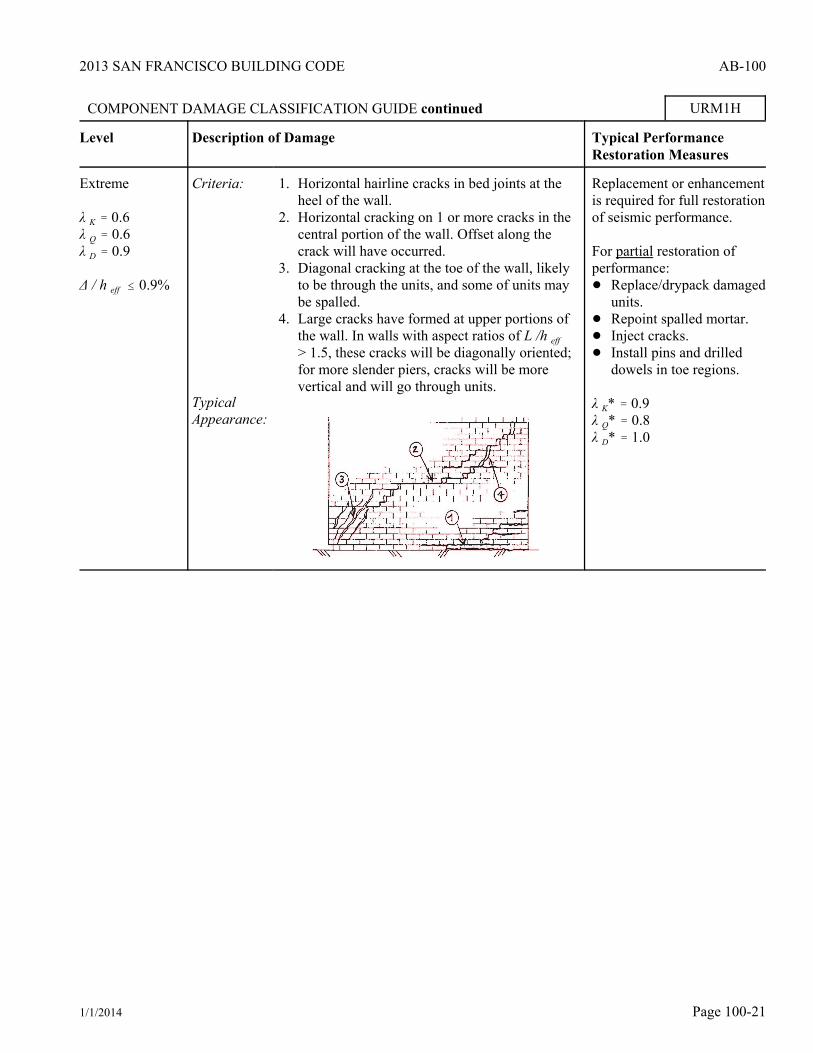
Extreme
λ K ' 0.6λ Q ' 0.6λ D ' 0.9
Δ / h eff # 0.9%
Criteria:
TypicalAppearance:
1. Horizontal hairline cracks in bed joints at theheel of the wall.
2. Horizontal cracking on 1 or more cracks in thecentral portion of the wall. Offset along thecrack will have occurred.
3. Diagonal cracking at the toe of the wall, likelyto be through the units, and some of units maybe spalled.
4. Large cracks have formed at upper portions ofthe wall. In walls with aspect ratios of L /h eff > 1.5, these cracks will be diagonally oriented;for more slender piers, cracks will be morevertical and will go through units.
Replacement or enhancementis required for full restorationof seismic performance.
For partial restoration ofperformance:! Replace/drypack damaged
units.! Repoint spalled mortar.! Inject cracks.! Install pins and drilled
dowels in toe regions.
λ K* ' 0.9λ Q* ' 0.8λ D* ' 1.0

2013 SAN FRANCISCO BUILDING CODE
1/1/2014Page 100-22
AB-100
COMPONENT DAMAGE System: URM
URM1M CLASSIFICATION GUIDE Component Type: Solid Wall
Behavior Mode: Out-of-Plane Flexural Response
How to distinguish behavior mode:
By observation:Out-of-plane failures are common in URM buildings. Usually theyoccur due to the lack of adequate wall ties, as discussed in Table7-1. When ties are adequate, the wall may fail due to out-of-planebending between floor levels. One mode of failure observed inexperiments is rigid-body rocking motion occurring on three cracks:one at the top of the wall, one at the bottom, and one at midheight.As rocking increases, the mortar and masonry units at the cracklocations can be degraded, and residual offsets can occur at thecrack planes. The ultimate limit state is that the walls rock too farand overturn. Important variables are the vertical stress on the walland the height-to-thickness ratio of the wall. Thus, walls at the topof buildings and slender walls are more likely to suffer damage.
By analysis:None required.
Caution:If horizontal cracks are located directlybelow wall-diaphragm ties, damage may bedue to bed joint sliding associated with tiedamage. For piers, if horizontal cracks areobserved at the top and bottom of the pierbut not at mid-height, see URM2A.Confirm whether the face brick isunbonded to the backing brick. If so, thethickness in the h/t requirement is reducedto the thickness of the backing wythes.
Refer to Evaluation Procedures for:
! In-plane wall behavior: See Section 7.3.5
Level Description of Damage Typical PerformanceRestoration Measures
Insignificant
For out-of-planeloads:
λ h/t ' 1.0
For in-planemodes givenpreviously,assume out-of-plane damageleads toModeratedamage forURM2B andInsignificantdamage for allother modes.
Criteria:
Typical Appearance:
1. Hairline cracks at floor/roof lines and mid-height of stories.
2. No out-of-plane offset or spalling of mortaralong cracks.
Not necessary for restorationof structural performance.(Measures may be necessaryfor restoration of nonstruc-tural characteristics.)

2013 SAN FRANCISCO BUILDING CODE
1/1/2014 Page 100-23
AB-100
COMPONENT DAMAGE CLASSIFICATION GUIDE continued URM1M
Level Description of Damage Typical PerformanceRestoration Measures
Slight Not Used
Moderate
For out-of-planeloads:
λ h/t ' 0.9
For in-planemodes, seeInsignificantdamage
Criteria:
TypicalAppearance:
1. Cracks at floor/roof lines and midheight ofstories may have mortar spalls up to full depthof joint and possibly:
2. Out-of-plane offsets along cracks of up to 1/8O.
See Insignificant damage above.
! Repoint spalled mortar:! For out-of-plane loads:λ h/t ' 1.0
! For in-plane loads: useModerate for URM2Band Insignificant for allother modes.
Heavy
For out-of-planeloads:
λ h/t ' 0.6
For in-planemodes givenpreviously,assume out-of-plane damageleads to Heavyfor all othermodes.
Criteria:
TypicalAppearance:
1. Cracks at floor/roof lines and midheight ofstories may have mortar spalls up to full depthof joint.
2. Spalling and rounding at edges of units alongcrack plane.
3. Out-of-plane offsets along cracks of up to 1/2O.
Replacement or enhancementis required for full restorationof seismic performance.
For partial restoration of out-of-plane performance:! Replace/drypack damaged
units! Repoint spalled mortarλ h/t ' 0.8
Extreme Criteria:
TypicalIndications
! Vertical-load-carrying ability is threatened! Significant out-of-plane or in-plane movement
cations at top and bottom of piers (“walking”).! Significant crushing/spalling of bricks at crack
locations.
! Replacement orenhancement required.

2013 SAN FRANCISCO BUILDING CODE
1/1/2014Page 100-24
AB-100
COMPONENT DAMAGE System: URM
URM2A CLASSIFICATION GUIDE Component Type: Weaker Pier
Behavior Mode: Wall-Pier Rocking
How to distinguish behavior mode:
By observation:Rocking-critical piers form horizontal flexural cracks at thetop and bottom of piers. Because the cracks typically closeas the pier comes back to rest at the end of ground shaking,these cracks can be quite subtle when only a few cycles ofrocking have occurred and when pier drift ratios duringshaking were small. As damage increases, softening of thepier can occur due to cracking, and the pier may begin to“walk” out-of-plane at the top and bottom. At the highestdamage levels, crushing of units at the corners can occur.
By analysis:As damage increases to the Moderate level andbeyond, some small cracking within the pier mayoccur. Confirm by analysis that rocking governsover diagonal tension and bed joint sliding.
Caution: If horizontal cracks are located directlybelow wall-diaphragm ties, damage may be due tobed joint sliding associated with tie damage. If ahorizontal crack is observed at midheight of thepier, see URM1M.
Refer to Evaluation Procedures for:
! In-plane wall behavior: See Section 7.3.2
Level Description of Damage Typical PerformanceRestoration Measures
Insignificant
λ K ' 0.8λ Q ' 1.0λ D ' 1.0
µ Δ # 1.5
Criteria:
Typical Appearance:
! Hairline cracks/spalled mortar in bed joints attop and bottom of pier.
Not necessary for restorationof structural performance.(Measures may be necessaryfor restoration of nonstruc-tural characteristics.)
Slight Not used.

2013 SAN FRANCISCO BUILDING CODE
1/1/2014 Page 100-25
AB-100
COMPONENT DAMAGE CLASSIFICATION GUIDE continued URM2A
Level Description of Damage Typical PerformanceRestoration Measures
Moderate
λ K ' 0.6λ Q ' 0.9λ D ' 1.0
Δ / h eff #h eff / L eff*0.4%
Criteria:
Typical Appearance:
1. Hairline cracks/spalled mortar in bed joints attop and bottom of pier.
2. Possible hairline cracking/spalled mortar inbed within piers.
Replacement or enhancementis required for full restorationof seismic performance.
For partial restoration ofperformance:! Repoint spalled mortar.
λ K* ' 0.8λ Q* ' 0.9λ D* ' 1.0
Heavy
λ K ' 0.4λ Q ' 0.8λ D ' 0.7
Δ / h eff #h eff / L eff*0.8%
Criteria:
TypicalAppearance:
1. Hairline cracks/spalled mortar in bed joints attop and bottom of pier, plus one or more of:
2. Hairline cracking/spalled mortar in bed jointswithin piers, but bed joints typically do notopen.
3. Possible out-of-plane or in-plane movement attop and bottom of piers (“walking”).
4. Crushed/spalled bricks at corners of piers.
Replacement or enhancementis required for full restorationof seismic performance.
For partial restoration ofperformance:! Replace/drypack damaged
units! Repoint spalled mortar! Inject cracks
λ K* ' 0.8λ Q* ' 0.9λ D* ' 1.0
Extreme Criteria:
TypicalIndications:
! Vertical load-carrying ability is threatened.! Significant out-of-plane or in-plane movement
at top and bottom of piers (“walking”).! Significant crushing/spalling of bricks at
corners of piers.
! Replacement orenhancement required.

2013 SAN FRANCISCO BUILDING CODE
1/1/2014Page 100-26
AB-100
COMPONENT DAMAGE System: URM
URM2B CLASSIFICATION GUIDE Component Type: Weaker Pier
Behavior Mode: Bed Joint Sliding
How to distinguish behavior mode:
By observation:In this type of behavior, sliding occurs on bed joints. Commonly observed both inthe field and in experimental tests, there are two basic forms: sliding on ahorizontal plane, and a stair-stepped diagonal crack where the head joints open andclose to allow for movement on the bed joint. Note that, for simplicity, the figuresbelow only show a single crack, but under cyclic loading, multiple cracks steppingin each direction are possible. Pure bed joint sliding is a ductile mode withsignificant hysteretic energy absorption capability. If sliding continues withoutleading to a more brittle mode such as toe crushing, then gradual degradation ofthe cracking region occurs until instability is reached. Theoretically possible, butnot widely reported, is the case of stair-stepped cracking when sliding goes so farthat an upper brick slides off a lower unit.
By analysis:Stair-stepped cracking mayresemble a form of diagonaltension cracking; confirm byanalysis that bed jointsliding governs overdiagonal tension.
Refer to Evaluation Procedures for:
! In-plane wall behavior: See Section 7.3.2
Level Description of Damage Typical PerformanceRestoration Measures
Insignificant
λ K ' 0.9λ Q ' 0.9λ D ' 1.0
µ Δ # 1.5
Criteria:
Typical Appearance:
1. Hairline cracks/spalled mortar in head and bedjoints either on a horizontal plane or in a stair-stepped fashion have been initiated, but nooffset along the crack has occurred and thecrack plane or stair-stepping is not continuousacross the pier.
2. No cracks in masonry units.
Not necessary for restorationof structural performance.(Measures may be necessaryfor restoration of nonstruc-tural characteristics.)
Slight Not used.

2013 SAN FRANCISCO BUILDING CODE
1/1/2014 Page 100-27
AB-100
COMPONENT DAMAGE CLASSIFICATION GUIDE continued URM2B
Level Description of Damage Typical PerformanceRestoration Measures
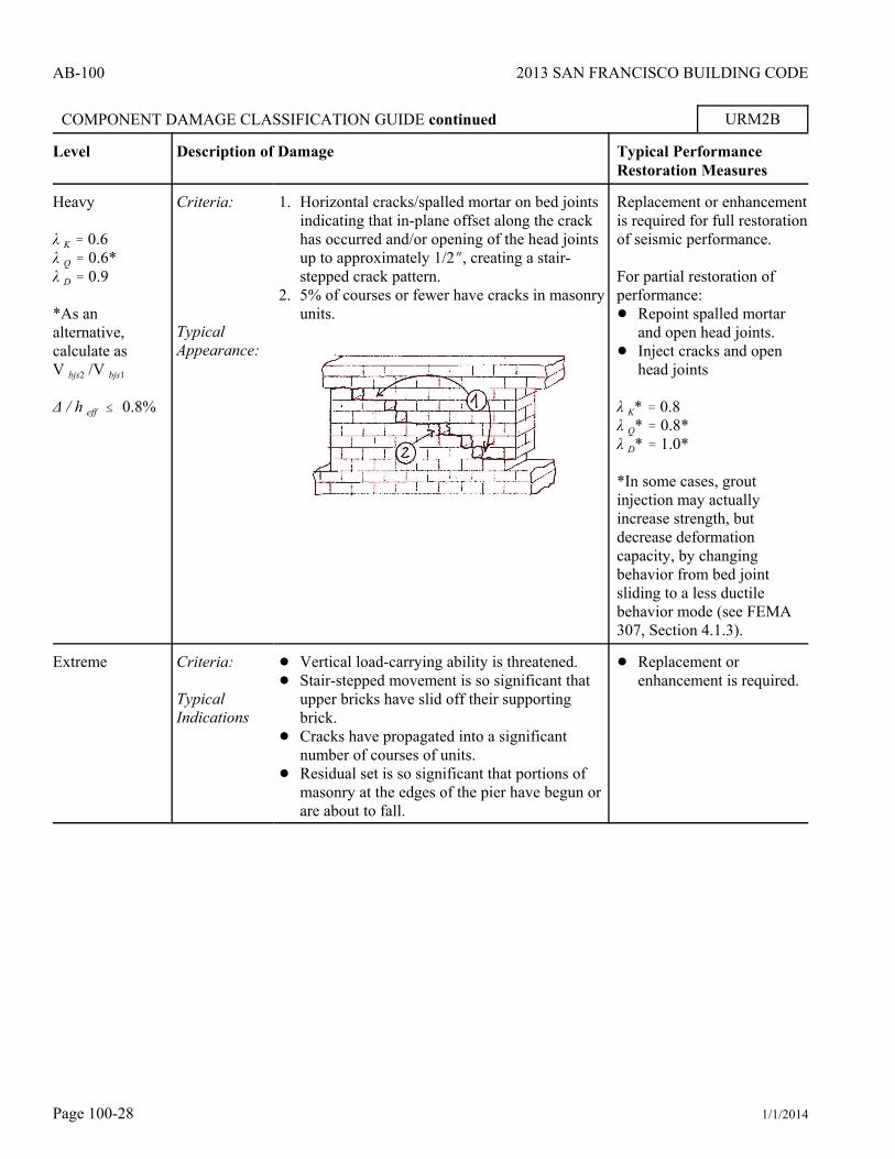
Moderate
λ K ' 0.8λ Q ' 0.6*λ D ' 1.0
*As analternative,calculate asV bjs2 /V bjs1
Δ / h eff # 0.4%
Criteria:
Typical Appearance:
1. Horizontal cracks/spalled mortar on bed jointsindicating that in-plane offset along the crackhas occurred and/or opening of the head jointsup to approximately 1/4O, creating a stair-stepped crack pattern.
2. 5% of courses or fewer have cracks in masonryunits.
Replacement or enhancementis required for full restorationof seismic performance.
For partial restoration ofperformance:! Repoint spalled mortar
and open head joints.! Inject cracks and open
head joints
λ K* ' 0.8λ Q* ' 0.8*λ D* ' 1.0*
*In some cases, groutinjection may actuallyincrease strength, butdecrease deformationcapacity, by changingbehavior from bed jointsliding to a less ductilebehavior mode (see FEMA307, Section 4.1.3).
2013 SAN FRANCISCO BUILDING CODE
1/1/2014Page 100-28
AB-100
COMPONENT DAMAGE CLASSIFICATION GUIDE continued URM2B
Level Description of Damage Typical PerformanceRestoration Measures
Heavy
λ K ' 0.6λ Q ' 0.6*λ D ' 0.9
*As analternative,calculate asV bjs2 /V bjs1
Δ / h eff # 0.8%
Criteria:
Typical Appearance:
1. Horizontal cracks/spalled mortar on bed jointsindicating that in-plane offset along the crackhas occurred and/or opening of the head jointsup to approximately 1/2O, creating a stair-stepped crack pattern.
2. 5% of courses or fewer have cracks in masonryunits.
Replacement or enhancementis required for full restorationof seismic performance.
For partial restoration ofperformance:! Repoint spalled mortar
and open head joints.! Inject cracks and open
head joints
λ K* ' 0.8λ Q* ' 0.8*λ D* ' 1.0*
*In some cases, groutinjection may actuallyincrease strength, butdecrease deformationcapacity, by changingbehavior from bed jointsliding to a less ductilebehavior mode (see FEMA307, Section 4.1.3).
Extreme Criteria:
TypicalIndications
! Vertical load-carrying ability is threatened.! Stair-stepped movement is so significant that
upper bricks have slid off their supportingbrick.
! Cracks have propagated into a significantnumber of courses of units.
! Residual set is so significant that portions ofmasonry at the edges of the pier have begun orare about to fall.
! Replacement orenhancement is required.

2013 SAN FRANCISCO BUILDING CODE
1/1/2014 Page 100-29
AB-100
COMPONENT DAMAGE System: URM
URM2K CLASSIFICATION GUIDE Component Type: Weaker Pier
Behavior Mode: Diagonal Tension
How to distinguish behavior mode:
By observation:Typical diagonal tension cracking & resulting from strong mortar, weakunits, and high compressive stress & can be identified by diagonal cracks(“X” cracks) that propagate through the units. In many cases, the crackingis sudden, brittle, and vertical load capacity drops quickly. The cracks maythen extend to the toe and the triangles above and below the crack separate.In a few cases, the load drop may be more gradual with cracks increasing insize and extent with each cycle. A second form of diagonal tensioncracking also has been experimentally observed with weak mortar, strongunits and low compressive stress where the cracks propagate in a stair-stepped manner in head and bed joints. The first (typical) case is shownbelow.
By analysis:Since the stair-stepping form ofcracking would appear similar to theearly levels of stair-stepped bedjoint sliding, confirm by analysisthat diagonal tension governs overbed joint sliding. Since deteriorationat the corners in the Heavy damagelevel may resemble toe crushing,also confirm that diagonal tensiongoverns over toe crushing.
Refer to Evaluation Procedures for:
! In-plane wall behavior: See Section 7.3.2
Level Description of Damage Typical PerformanceRestoration Measures
Insignificant
λ K ' 1.0λ Q ' 1.0λ D ' 1.0
µ Δ # 1
Criteria:
Typical Appearance:
1. Hairline diagonal cracks in masonry units infewer than 5% of courses.
Not necessary for restorationof structural performance.(Measures may be necessaryfor restoration of nonstruc-tural characteristics.)
Slight Not used.

2013 SAN FRANCISCO BUILDING CODE
1/1/2014Page 100-30
AB-100
COMPONENT DAMAGE CLASSIFICATION GUIDE continued URM2K
Level Description of Damage Typical PerformanceRestoration Measures
Moderate
λ K ' 0.8λ Q ' 0.9λ D ' 1.0
µ Δ . 1.5
Criteria:
Typical Appearance:
1. Diagonal cracks in pier, many of which gothrough masonry units, with crack widthsbelow 1/4O.
2. Diagonal cracks reach or nearly reach corners.3. No crushing/spalling of pier corners.
! Repoint spalled mortar.! Inject cracks.
λ K* ' 0.8λ Q* ' 1.0λ D* ' 1.0
Heavy
λ K ' 0.8λ Q ' 0.9λ D ' 1.0
µ Δ > 1.5
Criteria:
Typical Appearance:
1. Diagonal cracks in pier, many of which gothrough masonry units, with crack widths over1/4O.
2. Some minor crushing/spalling of pier cornersand/or
3. Minor movement along or across crack plane.
Replacement or enhancementis required for full restorationof seismic performance.
For partial restoration ofperformance:! Replace/drypack damaged
units.! Repoint spalled mortar.! Inject cracks.
λ K* ' 0.8λ Q* ' 0.8λ D* ' 1.0
Extreme Criteria:
Typical Appearance:
! Vertical load-carrying ability is threatened.! Significant movement or rotation along crack
plane.! Residual set is so significant that portions of
masonry at the edges of the pier have begun orare about to fall.
! Replacement orenhancement is required
2013 SAN FRANCISCO BUILDING CODE
1/1/2014 Page 100-31
AB-100
ATTACHMENT C
Excerpt from CUREE Publication No. EDA-02For full document, go to: http://www.curee.org/projects/EDA/docs/CUREE-EDA02-2-public.pdf
GENERAL GUIDELINES FOR THE ASSESSMENT AND REPAIR OFEARTHQUAKE DAMAGE IN RESIDENTIAL WOODFRAME BUILDINGS
February 2010
CUREEConsortium of Universities for Research in Earthquake Engineering
1301 South 46th StreetRichmond, CA 94804-4600
Phone: 510.665.3529; Fax: 510.665.3529e-mail: [email protected]; website: www.curee.org
4 Foundations and Slabs-on-Grade
4A.3 Footings or Stem Walls
1. For footings or stem walls surrounding a crawlspace, access as much of one side as possible and as much ofthe other side as practical (accounting for possible obstruction by plantings, hardscape, property line limits, etc.). On thebackside, seal the crack down to firm soil; on the front side (the exposed side from which the grout is injected), excavateto bottom of footing. Do not excavate beneath the footing. Clean crack, install ports, seal, and inject crack withappropriate grade material.
2. For footings or thickened edges surrounding slab-on-grade floors, only one-sided access is practical. Exposethe concrete to the bottom of the footing. Do not excavate beneath the footing. Clean crack, install ports, seal, and injectcrack with appropriate grade material.
3. For either one-sided or two-sided access, injection should begin at the lowest port and proceed upward to thetop of the stem wall or footing.
5 Walls
5.8 Repair Methodologies
The appropriate repair of lateral system and bearing walls must consider the nature, extent, cause, and significance ofthe damage. Where earthquake damage has occurred in other components of the house, wall repair should be consideredas one component of a more general repair plan. For example, if the house has been racked out of plumb, it should bestraightened prior to repairing wall finishes, doors, and windows. Where the damage is structurally significant, astructural repair will be necessary. In all other cases, a nonstructural repair is appropriate.
Table 5-1 gives appropriate repair methods for typical earthquake damage patterns. If the cause of an observed damagepattern cannot be determined, or if the damage is outside the description given in the table, a structures specialist shouldbe retained to specify appropriate repair. The repair methods listed in the table are further discussed below.
Note: The repair methods presented in this chapter presume that the building materials are free of regulated levels ofhazardous materials. If testing as recommended in Section 9.2.4 indicates the presence of regulated levels of asbestosor lead, the abatement and waste disposal recommendations of the environmental consultant should be incorporated intothe overall scope of repair.
Some California jurisdictions have local building code provisions that impose additional repair requirements if theearthquake damage exceeds either a certain percentage of the wall line’s strength or if the cost of repair exceeds a certainpercentage of the wall line’s replacement cost. Damage patterns described above as structurally insignificant represent
2013 SAN FRANCISCO BUILDING CODE
1/1/2014Page 100-32
AB-100
less than a ten percent capacity loss. Repair cost as a percentage of replacement cost may be estimated by a contractor.If the structural significance of the damage or the application of building code provisions are in question, an assessmentshould be performed by a structures specialist.
Table 5-1 does not include any jurisdiction-specific upgrade requirements. If such requirements apply, then anengineered repair will likely be needed.
5.8.1 Crack Repair
5.8.1.1 Stucco
• Fine cracks (i.e., 1/64-inch wide or narrower) should not be patched, especially if the stucco is not painted. Onpainted stucco, cracks this fine will be sealed by a fresh coat of paint. When determining the area to be painted,consideration should be given to obtaining a reasonably uniform appearance.
5.8.1.2 Drywall
• Where cracking follows panel joints or corner beads, existing tape and compound should be removed. The jointshould then be retaped, retextured, and repainted. When determining the area to be retextured and repainted,consideration should be given to obtaining a reasonably uniform appearance.
• Short (less than about 6-inches long) cracks less than about 1/64-inch wide extending from the corners ofopenings may be patched using drywall tape and joint compound, retextured and repainted. When determining the areato be retextured and repainted, consideration should be given to obtaining a reasonably uniform appearance.
• Where cracks greater than about 6-inches long extend through the drywall, the cracked piece should beremoved to the nearest stud on either side of the crack (32-inch minimum width, 48-inch height) and replaced, retextured,and repainted. When determining the area to be retextured and repainted, consideration should be given to obtaining areasonably uniform appearance.
• Nail pops may be repaired by adding a drywall screw adjacent to the nail pop, resetting or removing the“popped” fastener, patching, retexturing to match the adjacent finish and repainting. When determining the area to beretextured and repainted, consideration should be given to obtaining a reasonably uniform appearance.
5.8.1.3 Gypsum Lath and Plaster
Where the plaster is cracked but remains firmly attached to the lath, repairs can be accomplished by cleaning the crackand patching, texturing, and painting to match the existing surface texture and finish. When determining the area to beretextured and repainted, consideration should be given to obtaining a reasonably uniform appearance.
5.8.2 Construction Joints
Where minor movement has occurred at construction joints, only cosmetic repairs are necessary. Where these joints weresimply painted, the appropriate repair is to clean and repaint the joint. Where caulking and/or grout along the joints hascracked or spalled (such as along shower enclosures), the appropriate repair is to remove the cracked material, clean theseparation, and recaulk or regrout the joint where necessary. It should be noted that even after the repairs are complete,cracks and/or separations may reappear due to the normal effects of material shrinkage, temperature changes, and minordifferential movements of supporting elements (soil or structure). The reoccurrence of damage is unrelated to theearthquake. If damage occurred because there was no joint where there should have been one, then again, the damageis generally not structurally significant.
5.8.3 Technical Consultant Repair Recommendations
The following repair procedures are typical repairs that might be recommended in a structures specialist report. Theyshould not be used in the absence of recommendation by a structures specialist and are presented here for reference only.

2013 SAN FRANCISCO BUILDING CODE
1/1/2014 Page 100-33
AB-100
5.8.3.1 Stucco Repair
Where the stucco has buckled, delaminated, detached from the framing, or is severely cracked, the existing stuccoshould be removed back to intact, securely attached stucco. The underlying building paper should be repaired or replacedas necessary, and any new paper should be properly lapped with the existing paper. New wire mesh should be installedand nailed to the framing and it should overlap existing mesh by at least 6 inches. Stucco should be applied, in threecoats, to match the existing thickness and surface finish. The stucco should be refinished as necessary to match adjacentareas. When determining the area to be refinished, consideration should be given to obtaining a reasonably uniformappearance.
5.8.3.2 Drywall Repair
Fractured gypsum wallboard panels should be replaced in kind. Where the attachment of the drywall to the framinghas loosened significantly, new fasteners should be installed around the wall perimeter and along panel joints showingsigns of relative movement. The repaired areas should be refinished as necessary to match adjacent areas. Whendetermining the area to be refinished, consideration should be given to obtaining a reasonably uniform appearance.
5.8.3.3 Plaster Repair
Where the lath has fractured (or where plaster damage suggests fracture of the gypsum lath), the damaged piecesshould be removed to soundly attached plaster and/or lath, new lath installed and the area replastered. Where larger areasof repair are involved, and it is more economical to do so, lath and plaster should be removed to the limits of the wallpanel and replaced with drywall.53 When determining the area to be refinished, consideration should be given toobtaining a reasonably uniform appearance.
5.8.3.4 Framing Repair
Severe damage to stucco or interior wall finishes indicates substantial wall racking and the possibility of damage towoodframing members, especially nailed connections at the sill or top plates. These conditions call for assessment bya structures specialist. If framing damage is found, replacement, renailing, or “sistering” of the affected members isusually the appropriate repair, but that judgment should be left to the structures specialist.
5.8.3.5 Building Realignment
When a building has been permanently racked out of plumb by more than 1/2 inch over a height of eight feet, asevidenced by a consistent pattern of damage to finishes, inoperable doors and/or windows, and out-of-plumbmeasurements of door and window jambs, it will generally be necessary to remove finishes from the racked walls, plumbthe building, and reinstall finishes. It is essential to distinguish between overall earthquake-induced racking of thebuilding and normal construction tolerances or other pre-existing conditions.
5.8.4 Permits, Upgrades, and Retrofits
Depending upon the nature and scope of damage and proposed repair, building permits and other government agencyapprovals may be required by the local jurisdiction. In addition to normal changes in the building code over time, somejurisdictions have building code requirements that mandate upgrading portions or all of the building, if certain damagethresholds are exceeded. Check with the local building department to determine the existence of any, applicable localrequirements.
• For cracks up to 1/8-inch wide, the crack should be opened to the brown coat by beveling the crack edges to acceptpatching material. Patch with flexible vinyl base patching compound. Stucco should be applied to match the existingsurface texture, as necessary. The stucco should be refinished as necessary to match adjacent areas. When determiningthe area to be refinished, consideration should be given to obtaining a reasonably uniform appearance.
53 If drywall is used, modification of trim at ceilings, floors, windows, and doors, may be necessary. If the plaster being replacedis 5/8-inch thick plaster reinforced with expanded metal lath over 3/8-inch gypsum lath, it may be necessary to install 1/2-inchplywood sheathing beneath the drywall to restore the strength of the wall assembly. Installation of 1/2-inch plywood willeliminate the need for modification of trim, in most cases.
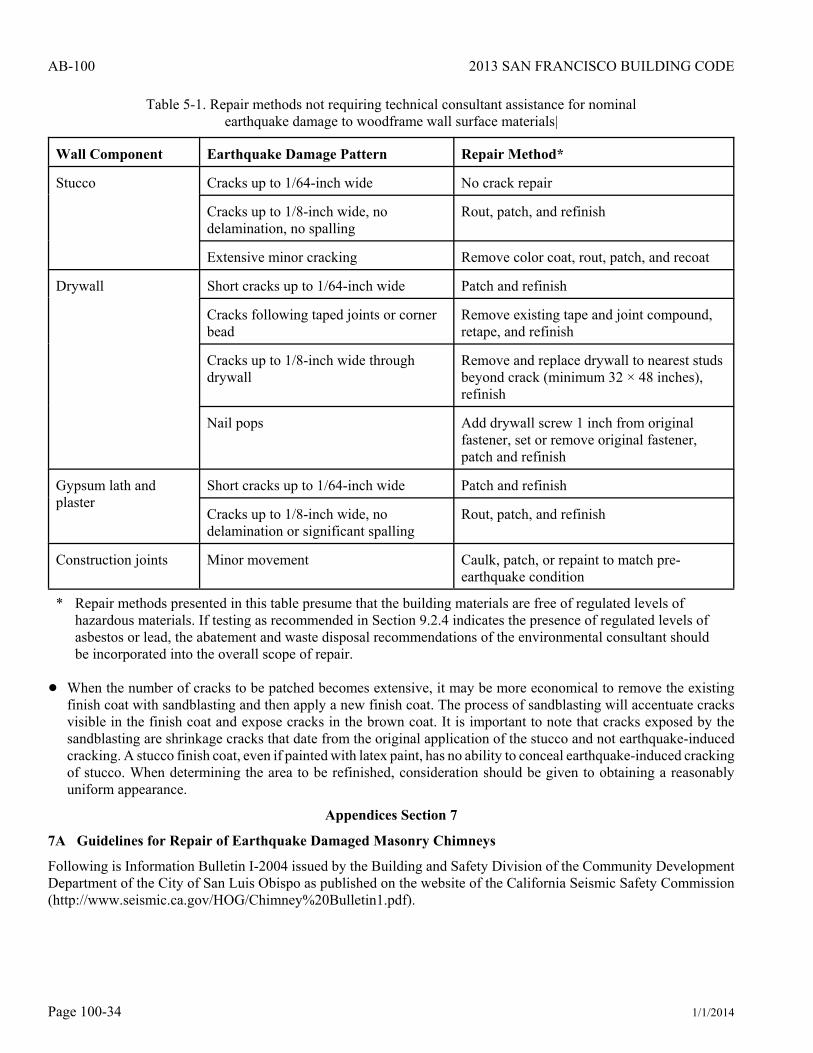
2013 SAN FRANCISCO BUILDING CODE
1/1/2014Page 100-34
AB-100
Table 5-1. Repair methods not requiring technical consultant assistance for nominalearthquake damage to woodframe wall surface materials|
Wall Component Earthquake Damage Pattern Repair Method*
Stucco Cracks up to 1/64-inch wide No crack repair
Cracks up to 1/8-inch wide, nodelamination, no spalling
Rout, patch, and refinish
Extensive minor cracking Remove color coat, rout, patch, and recoat
Drywall Short cracks up to 1/64-inch wide Patch and refinish
Cracks following taped joints or cornerbead
Remove existing tape and joint compound,retape, and refinish
Cracks up to 1/8-inch wide throughdrywall
Remove and replace drywall to nearest studsbeyond crack (minimum 32 × 48 inches),refinish
Nail pops Add drywall screw 1 inch from originalfastener, set or remove original fastener,patch and refinish
Gypsum lath andplaster
Short cracks up to 1/64-inch wide Patch and refinish
Cracks up to 1/8-inch wide, nodelamination or significant spalling
Rout, patch, and refinish
Construction joints Minor movement Caulk, patch, or repaint to match pre-earthquake condition
* Repair methods presented in this table presume that the building materials are free of regulated levels ofhazardous materials. If testing as recommended in Section 9.2.4 indicates the presence of regulated levels ofasbestos or lead, the abatement and waste disposal recommendations of the environmental consultant shouldbe incorporated into the overall scope of repair.
! When the number of cracks to be patched becomes extensive, it may be more economical to remove the existingfinish coat with sandblasting and then apply a new finish coat. The process of sandblasting will accentuate cracksvisible in the finish coat and expose cracks in the brown coat. It is important to note that cracks exposed by thesandblasting are shrinkage cracks that date from the original application of the stucco and not earthquake-inducedcracking. A stucco finish coat, even if painted with latex paint, has no ability to conceal earthquake-induced crackingof stucco. When determining the area to be refinished, consideration should be given to obtaining a reasonablyuniform appearance.
Appendices Section 7
7A Guidelines for Repair of Earthquake Damaged Masonry Chimneys
Following is Information Bulletin I-2004 issued by the Building and Safety Division of the Community DevelopmentDepartment of the City of San Luis Obispo as published on the website of the California Seismic Safety Commission(http://www.seismic.ca.gov/HOG/Chimney%20Bulletin1.pdf).