2013 canadian consulting engineering awards full project
TRANSCRIPT

Page 1
2013 CANADIAN CONSULTING ENGINEERING AWARDSFULL PROJECT DESCRIPTION
NAME: WINNIPEG’S FIRST RAPID TRANSIT CORRIDOR – SOUTHWEST TRANSITWAYCLIENT: CITY OF WINNIPEG – TRANSIT DEPARTMENTFIRM: DILLON CONSULTING LIMITED
1 PROJECT BACKGROUND
With an area population of 750,000 people, Winnipeg is growing at a pace that has not been seen in several decades.
While this growth presents challenges, it provides opportunities for innovative and proactive transportation solutions to
support Winnipeg’s prosperity in an economically, socially, and environmentally sustainable manner. The development
of a rapid transit system is a key component of the City’s Transportation Master Plan to provide citizens with a viable
alternative to the automobile, to reduce road congestion, and to build a transportation system that serves future
generations.
Winnipeg began a multi-year comprehensive transit improvement program in 2007 that involved an accelerated
program of bus replacements, the implementation of upgrades to major stops and terminals, transit priority measures, a
leading-edge implementation of Intelligent Transportation System (ITS) technology for transit, and new park & ride
facilities. Physical improvements are concentrated in the city’s “Transit Quality Corridors” where high levels of transit
service operate. These measures, in combination with real-time passenger information made possible by the ITS
deployment, are designed to enhance the speed, reliability, comfort, accessibility, and convenience of the city’s transit
service.
While the transit priority component of the improvement program includes such on-street measures as new diamond
lands, queue jumps, and priority signals for buses, its most significant element is the development of a rapid transit
network for the city. Operating in exclusive transit-only corridors, rapid transit in Winnipeg will shift a higher proportion
of urban travel to the transit system by offering a higher order service characterized by high speed, high reliability,high frequency, real-time passenger information, modern ITS-equipped vehicles, a flexible route network,beautiful stations, a high quality runningway, and a distinct image.
Dillon Consulting Limited was assigned responsibility for the design and construction management of the initial phase of
the rapid transit network, Stage 1 of the Southwest Rapid Transit Corridor. Following the announcement of a funding
agreement for the project by the three levels of government in 2008, Dillon was tasked with fast-tracking this complex
$138 million project to achieve a targeted completion by the end of 2011. The project was delivered “on time and on
budget”, and following Winnipeg Transit’s commissioning, testing, and training period, rapid transit service began
operation on April 8, 2012.
2 THE SOUTHWEST TRANSITWAY
The Southwest Transitway is a high-speed roadway for buses, physically separated from the regular street system.
Buses operate at speeds up to 80 kph, free of any other traffic, providing very fast, reliable service. Stage 1 of the
transitway extends from Queen Elizabeth Way & Stradbrook to Pembina & Jubilee. Stage 2, planned for construction by
2018, will extend the transitway further south from Pembina & Jubilee to Bison Drive/University of Manitoba.

2013 Canadian Consulting Engineering AwardsFull Project Description: Winnipeg’s First Rapid Transit Corridor – Southwest Transitway
Page 2
Figure 1: Southwest Transitway Alignment – Overall Project
For the completed Stage 1 section of the transitway, there are two major structures: Osborne Station built atop a newbridge that overpasses Osborne Street and a tunnel beneath the CN rail line. Bus-only access roads between the
transitway and the street system let rapid transit buses operate both on the street and on the transitway. This routingflexibility provides one-seat travel without transfer for most passengers. Buses transition between the street system andthe transitway at Queen Elizabeth & Stradbrook, at Harkness Station near Stradbrook & Harkness, at the east end ofWarsaw Avenue, and at the Jubilee Overpass. Transit priority signals are used at several of these locations to provideefficient bus access/egress to/from the transitway. There is also a bus-only access road to the transitway at the FortRouge Transit Base. This provides a fast, efficient way for buses to travel between the garage and route terminals at
the start and end of service.
There are 13 routes that operate on the Southwest Transitway. Most of the rapid transit routes operate between thenew Balmoral Station (former Greyhound Inter-City Bus Station – upgrade design/construction performed by Dillon as aseparate project) at the University of Winnipeg in the downtown and various destinations in southwest Winnipeg.These routes use the Graham Transit Mall and diamond lanes on Main Street to access the transitway at QueenElizabeth Way & Stradbrook. The rapid transit routes then operate at high speed on the transitway (serving Harkness,Osborne, Fort Rouge Stations, and a stop at the Jubilee Overpass), then exit the transitway at the Jubilee Overpass to
proceed south on Pembina Highway, then branch off Pembina Highway at several points to the routes’ ultimatedestinations.
Routes that operate on Grant Avenue also use the Graham Mall, the Main Street diamond lanes, and the north portionof the Transitway between Queen Elizabeth Way and Warsaw Avenue (stopping at Harkness and Osborne Stations).At the east end of Warsaw Avenue, they use a bus-only link to exit the Transitway onto Warsaw and, from there, travel
via Pembina to Grant Avenue.
3 PROJECT SCOPEBased on Dillon’s functional and preliminary design work, funding for the detailed design and construction of Stage 1 ofthe Southwest Transitway was approved in 2008, with an aggressive construction completion target set by the client forthe end of 2011. To achieve that target, a fast-track schedule for final design and construction was developed by
separating the project into the following tendered contracts:

2013 Canadian Consulting Engineering AwardsFull Project Description: Winnipeg’s First Rapid Transit Corridor – Southwest Transitway
Page 3
Contract Description
1 Land Drainage Sewer (2.5 km)
2 Land Drainage Pumping Station for the Transitway Tunnel
3 Transitway Roadway – Queen Elizabeth Way to Osborne Station (3.6 km)
4 Transit Tunnel beneath 7 tracks of CN mainline (350 metres)
5 Bridge (100 metres) over Osborne Street, including Osborne Station atop the Bridge
6 Transitway Roadway – Tunnel to Jubilee; Landscaping
7 Station Construction, Warsaw Reconstruction
3.1 Contracts 1 and 2: Land Drainage Sewer and Pumping Station
The City of Winnipeg’s urban land drainage system has two main types: combined sewer and separate land drainagesewer systems. Stage 1 of the Southwest Transitway straddles a number of Combined Sewer Districts including the
River Sewer District adjacent to the northern portion of the right-of-way, the Baltimore/Jessie Sewer District in the
central part, and the Cockburn Sewer District at the southern end of the transitway. As some of these Districts are
already beyond capacity, a land drainage study was undertaken to determine possible drainage options for both the
transitway and its immediately adjoining lands.
Based on site characteristics, two distinct drainage areas were established. Drainage Area 1 included lands adjacent
to the southern part of the transitway between Jubilee Avenue and Osborne Street. It is a brownfield site with no
existing development, sewers, or streets in close proximity to the transitway. Drainage Area 2 included the urbanized
lands around the northern part of the transitway between Osborne Street and Queen Elizabeth Way.
Drainage Area 1 required a new land drainage sewer with a separate
discharge to the Red River via an existing outfall at Glasgow Avenue.
Connections to the existing combined sewer system were not
feasible as the existing system is at capacity. This new separatesewer drains the transitway tunnel, the transitway roadway south of
the tunnel, the CN-owned lands located between the mainline and
the transitway, and the privately-owned lands in the Fort Rouge
Yards immediately east of the transitway. After extensive input from
Dillon, the City approved this sewer design as it provides sufficient
capacity to accommodate the future development of the Fort Rouge
Yards lands. The development agreement for the Fort Rouge Yards
includes a provision for the City to recover from the developer the
portion of the land drainage sewer installation costs attributable to the developer’s lands.
Drainage Area 2, located in the urbanized area of Donald Street, includes both a combined and a separated sewer
system. The overall study concluded that any existing catchbasin inlets tied into the combined sewer be diverted to the
land drainage sewer, and that any new transitway inlets be connected to the existing land drainage system.
Contract 1, with a value of over $5 million in underground works, involved the installation of the land drainage sewer. Itincluded installation of new manholes, abandonment of sewers and manholes, restoration of gravel access
roads/pavements/boulevards, and sewer video inspection. A major component was the installation of 350 metres of
Figure 2 – Large Diameter Pipe InstallationUsing TBM
2013 Canadian Consulting Engineering AwardsFull Project Description: Winnipeg’s First Rapid Transit Corridor – Southwest Transitway
Page 4
large diameter (1350 mm) pipe immediately adjacent to the bus storage garage at the Fort Rouge Transit Base. The
Tunnel Boring Method (TBM) was used for the installation of the sewer in this area as it provided minimal disruption to
the high volume of bus access/egress movements each day and it was less costly than other construction methods.
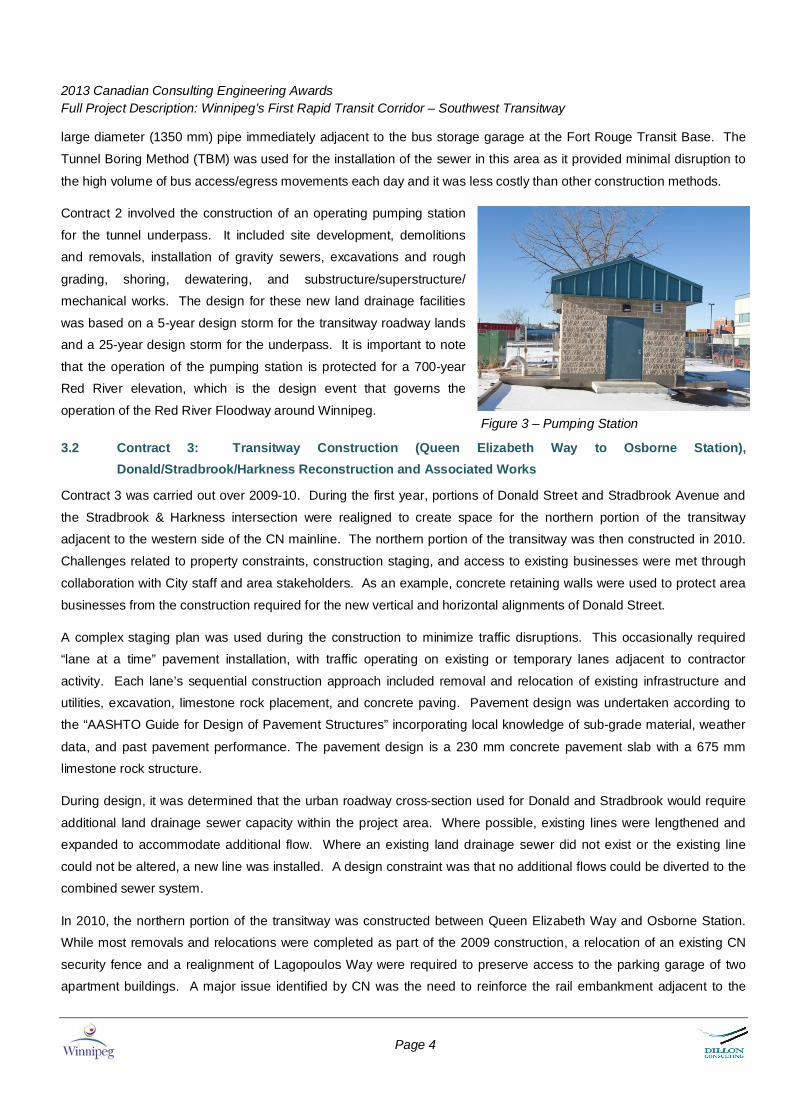
Contract 2 involved the construction of an operating pumping station
for the tunnel underpass. It included site development, demolitionsand removals, installation of gravity sewers, excavations and rough
grading, shoring, dewatering, and substructure/superstructure/mechanical works. The design for these new land drainage facilities
was based on a 5-year design storm for the transitway roadway landsand a 25-year design storm for the underpass. It is important to note
that the operation of the pumping station is protected for a 700-yearRed River elevation, which is the design event that governs the
operation of the Red River Floodway around Winnipeg.
3.2 Contract 3: Transitway Construction (Queen Elizabeth Way to Osborne Station),Donald/Stradbrook/Harkness Reconstruction and Associated Works
Contract 3 was carried out over 2009-10. During the first year, portions of Donald Street and Stradbrook Avenue and
the Stradbrook & Harkness intersection were realigned to create space for the northern portion of the transitwayadjacent to the western side of the CN mainline. The northern portion of the transitway was then constructed in 2010.
Challenges related to property constraints, construction staging, and access to existing businesses were met through
collaboration with City staff and area stakeholders. As an example, concrete retaining walls were used to protect area
businesses from the construction required for the new vertical and horizontal alignments of Donald Street.
A complex staging plan was used during the construction to minimize traffic disruptions. This occasionally required“lane at a time” pavement installation, with traffic operating on existing or temporary lanes adjacent to contractor
activity. Each lane’s sequential construction approach included removal and relocation of existing infrastructure andutilities, excavation, limestone rock placement, and concrete paving. Pavement design was undertaken according tothe “AASHTO Guide for Design of Pavement Structures” incorporating local knowledge of sub-grade material, weather
data, and past pavement performance. The pavement design is a 230 mm concrete pavement slab with a 675 mmlimestone rock structure.
During design, it was determined that the urban roadway cross-section used for Donald and Stradbrook would require
additional land drainage sewer capacity within the project area. Where possible, existing lines were lengthened andexpanded to accommodate additional flow. Where an existing land drainage sewer did not exist or the existing line
could not be altered, a new line was installed. A design constraint was that no additional flows could be diverted to thecombined sewer system.
In 2010, the northern portion of the transitway was constructed between Queen Elizabeth Way and Osborne Station.While most removals and relocations were completed as part of the 2009 construction, a relocation of an existing CN
security fence and a realignment of Lagopoulos Way were required to preserve access to the parking garage of twoapartment buildings. A major issue identified by CN was the need to reinforce the rail embankment adjacent to the
Figure 3 – Pumping Station

2013 Canadian Consulting Engineering AwardsFull Project Description: Winnipeg’s First Rapid Transit Corridor – Southwest Transitway
Page 5
Harkness Station site. To address this, a sheet pile wall was installed between the embankment and the station to a
depth of approximately 15 metres.
This work was followed by the construction of the transitway: excavation,placement of sub-base limestone, and pouring of concrete pavement with atraffic barrier on either side. During construction, special attention was paid totwo 69 kilovolt power lines beneath the centreline of a 300-metre length of thetransitway adjacent to Donald Street. The depths of the lines averaged 0.5metres below the bottom of excavation. Manitoba Hydro required that at least0.45 metres of in-situ cover be maintained on the lines, that no vibratorycompaction take place immediately above the lines, and that a Manitoba Hydroinspector be on site during all excavation activities above and adjacent to thelines.
Ancillary works of Contract 1 included the reconstruction of Scott Street andGertrude Avenue to tie in with the relocated sections of Donald Street, and theconstruction of new active transportation paths along the east side of Donaldand the south side of Stradbrook as new links in the City’s growing activetransportation network.
To integrate transitway operations with the street network, new traffic signalswere installed at Stradbrook & Harkness to accommodate bus egress fromHarkness Station and traffic signal timing plans at the intersection and thoseupstream and downstream of it were reconfigured.
3.3 Contract 4: Transitway Tunnel
Built in two phases, the transitway tunnel is a 200-metre cast-in-place concretestructure with an additional 150 metres of retaining/wing walls. It wasstructurally shored during construction, required three phases of CN trackrelocation, features a 67° skew at the construction joint, and can accommodatea future conversion of the transitway to a light rail transit (LRT) alignment.
During design, extensive consultation was undertaken with several
stakeholders to reach a workable and cost-effective tunnel solution tounderpass the CN mainline. These stakeholders included CN, Citydepartments, utilities, adjacent property owners, and the City’s ActiveTransportation Advisory Committee.
Several structural design options were initially considered, including overpassand tunnel coring alternatives, but were eliminated due to property constraints,
unsuitable site conditions, and cost. A structurally-shored open-cut approachwith cast-in-place construction was selected due to simplicity and a robustresistance to water penetration. A Value Engineering exercise led by
Figure 4 – View of Corridor Parallelto Donald Street Looking South
Figure 5 – Tunnel Construction
2013 Canadian Consulting Engineering AwardsFull Project Description: Winnipeg’s First Rapid Transit Corridor – Southwest Transitway
Page 6
specialists within the engineering and construction community was undertaken to review the selected design andidentify improvements.
Given transitway alignment requirements to accommodate high speeds (grades, curve radii) and existing property
constraints, the tunnel was required to underpass the seven tracks at a significant skew. This created a significant
challenge to meet CN’s requirement that tunnel construction not interfere with rail operations. As complete closure of
all seven tracks for the duration of the construction was unacceptable to CN, construction was staged in a manner to
maintain rail operations. Some tracks were closed and new switches were installed to transfer trains to the four
mainline tracks required to be maintained during the two stages of tunnel construction. To meet the requirements of
both CN and the City, the tunnel construction was phased as follows:
Phase Description1 First CN Track Detour: Non-essential tracks removed and remaining tracks shifted eastward of CN’s permanent
alignment to accommodate the construction of the west half or the tunnel.2 Construction of West Half of Tunnel3 Second CN Track Detour: Tracks shifted westward of CN’s permanent alignment to accommodate the construction of
the east half of the tunnel4 Construction of the East Half of Tunnel5 Re-installation and re-location of all seven tracks to CN’s original permanent alignment above the completed tunnel
The tunnel’s scope of work included installation of gravity sewers, demolition and removals, groundwater
depressurization, dewatering, and structural/architectural/electrical works.
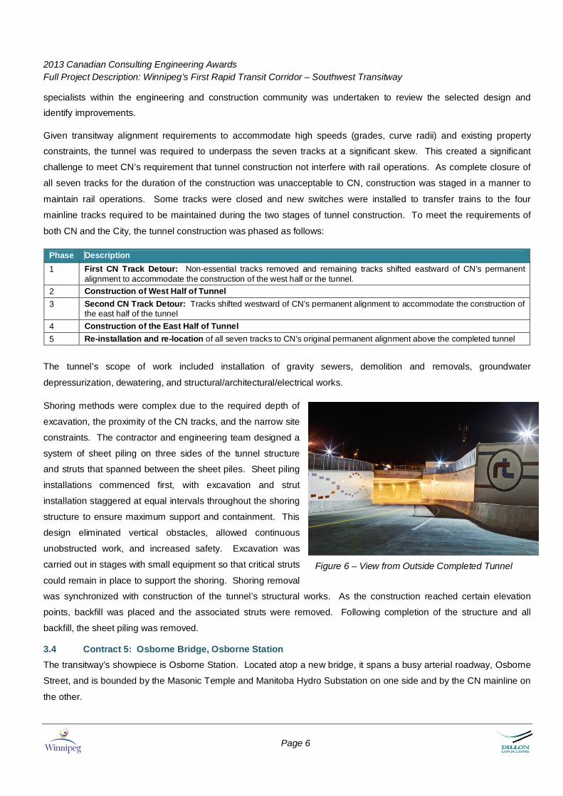
Shoring methods were complex due to the required depth of
excavation, the proximity of the CN tracks, and the narrow site
constraints. The contractor and engineering team designed a
system of sheet piling on three sides of the tunnel structure
and struts that spanned between the sheet piles. Sheet piling
installations commenced first, with excavation and strut
installation staggered at equal intervals throughout the shoring
structure to ensure maximum support and containment. This
design eliminated vertical obstacles, allowed continuous
unobstructed work, and increased safety. Excavation was
carried out in stages with small equipment so that critical struts
could remain in place to support the shoring. Shoring removal
was synchronized with construction of the tunnel’s structural works. As the construction reached certain elevation
points, backfill was placed and the associated struts were removed. Following completion of the structure and all
backfill, the sheet piling was removed.
3.4 Contract 5: Osborne Bridge, Osborne StationThe transitway’s showpiece is Osborne Station. Located atop a new bridge, it spans a busy arterial roadway, Osborne
Street, and is bounded by the Masonic Temple and Manitoba Hydro Substation on one side and by the CN mainline on
the other.
Figure 6 – View from Outside Completed Tunnel

2013 Canadian Consulting Engineering AwardsFull Project Description: Winnipeg’s First Rapid Transit Corridor – Southwest Transitway
Page 7
Osborne Station consists of a fully enclosed steel
structure over a steel “I” girder bridge with a reinforced
concrete bridge deck. The bridge has a total length of
70.5 metres with two abutments and two piers. The
curved steel structure (12.8 metre height) over the
bridge has a total length of 99.7 metres complete with
smaller wind baffles (4.8 metre height) on either side to
limit the exposure to the elements inside the station.
The structure forms the backbone of a complex
building that includes electronic passenger information
displays, information kiosks, benches, illuminated
signage, heaters, fire protection, bus exhaust
management, lighting, and a bus detection and warning
system.
Passenger access to the station is gained from either side of Osborne Street. On the west side, there is an accessible
ramp with an overhead canopy. On the east side, a large plaza provides a gathering and resting area as well as ramp
access to the station. Both access points are fully landscaped with trees, shrubs, and native plants. All aspects of the
station (plazas, ramps, sidewalks, station interior) incorporate Universal Design, with visual and tactile cues in all
locations.
There were many design challenges for this element of the project:
A skew angle of 51º for the bridge and building had to be maintained within a small footprint.
The site constraints required that the bridge’s width be narrowed to 9.4 metres from an originally contemplated 15.5
metres. This required the termination of exterior girders at the west pier. To mimic the profile of continuous
girders, innovative methods of analysis were used to generate a design that cast the terminated girders into the
pier. This arrangement avoids damage to the concrete caused by differential movement of the girders.
To provide sufficient roadway clearance beneath the bridge and the necessary vertical curvature of the transitway
on the bridge, a very shallow bridge girder was necessary. Because the bridge design must sustain LRT loadings,
thick member sizes and tight girder spacings were used. Site conditions dictated various span lengths, with a long
center span and shorter end spans. This variability created uplift forces at the abutments under live load. To
resolve this, a large dead load of non-compositely acting concrete was placed in the area between the end span
girders.
Expansion/contraction effects due to temperature variations were required to be considered in the design for both
the bridge and the station superstructure, as the station is not completely enclosed and heated. As the fixed points
of the bridge and building superstructure are different, the superstructure could not be braced to the bridge. This
required significantly larger member sizes for the side truss supports.
These design challenges had major implications for construction. The space available for stockpiling materials and
construction was very limited. A rigorous staging schedule was required to ensure that construction activities occurred
without conflicts. Construction was conducted over a busy arterial roadway and only limited closures were permitted
Figure 7 – View from Inside Osborne Station duringConstruction

2013 Canadian Consulting Engineering AwardsFull Project Description: Winnipeg’s First Rapid Transit Corridor – Southwest Transitway
Page 8
during the project’s year and a half duration. Extensive hoardings and platforms were required to provide protection to
traffic and pedestrians below the bridge.
The proximity to the CN main line also required careful staging for the excavation works. Some excavations were
within 5 metres of active tracks and shoring had to be provided in a very specific manner to avoid any horizontal or
vertical deflection of the tracks. Any equipment that could potentially foul the tracks was required to be locked down
during the passage of trains, which often slowed construction on an already tight schedule.
The subsurface conditions on the site were highly variable and
required highly specialized excavation techniques for the
construction of rock-socketed concrete caissons. As
examples, complications that arose included a high water
table, uneven bedrock, a large fractured rock layer above the
bedrock, a deep till layer with both large and small boulders
and fine sands. To maintain positive hydrostatic pressure and
the integrity of the caisson shaft and to prevent deterioration of
the rock strata, upwards of 10,000 litres of water were required
to be injected into the shafts following excavation.
There was an extensive network of underground utilities on site including pressurized oil-filled electrical ducts, a large
combined sewer, and communication ducts. It was uncommon for any excavation to occur on site without encountering
a utility line. Extreme caution was required whenever any excavation was required, regardless of depth of cut.
3.5 Contract 6: Transitway Construction (Osborne Station to Jubilee); Landscaping; & Associated WorksContract 6 was carried out over 2010-11. The first year’s
activities included site clearance, construction of the
transitway between the south end of the tunnel and Jubilee
Avenue, construction of a new bus access/egress between
the Fort Rouge Transit Base and the transitway, and
installation of connections to the land drainage sewer.
Activities in 2011 included construction of the transitway from
Osborne Station through the tunnel to the transit base
access/egress approach, the construction of an extension of
Morley Avenue and loop roads/parking at Fort Rouge Station,
reconstruction of VIA Rail’s employee parking lot (including
paving, fence relocation, electrical works), and construction of
a parking area at the tunnel’s pumping station.
The transitway pavement design used for the northern portion under Contract 3 was also used for this contract and
involved excavation, limestone sub-base placement, and concrete paving. Concrete was placed using a paver, 8.2
metres in width, with an integral mountable curb on either side.
Figure 8 – Osborne Street Station
Figure 9 – Slipform Paving of Transitway

2013 Canadian Consulting Engineering AwardsFull Project Description: Winnipeg’s First Rapid Transit Corridor – Southwest Transitway
Page 9
The construction required detailed coordination with other contracts and other projects. Between Osborne Station and
the north end of the tunnel, the area was quite confined and, at times, 3 general contractors and 10 subcontractors
were working concurrently. At the intersection of the transitway and the Jubilee Overpass, coordination was required
with those responsible for the Jubilee Overpass rehabilitation project to ensure proper grades were installed at the bus
egress and access locations at the overpass. Several drainage connections were made throughout the length of the
transitway to the land drainage sewer installed under Contract 1. In addition, several pipe segments were installed from
the mainline sewer to the property line to accommodate the Fort Rouge Yards development.
3.6 Contract 7: Station Construction (Tunnel to Jubilee); Warsaw ReconstructionThis wrap-up contract included fabrication and installation of all station elements for Harkness Station and Fort Rouge
Station, the reconstruction of Warsaw Avenue between Osborne Station and Pembina Highway, and
landscaping/aesthetic treatments for the complete project.
The station elements included large heated shelters,
overhead canopies over the platform, pedestrian lighting,
illuminated signage, information kiosks, electronic
BUSwatch signs to display real-time bus departure
information, bike racks and lockers, benches, recycling
receptacles, universal design features, a centre median
fence to prevent jay-walking across the transitway, and
fencing to guide pedestrians to designated crosswalks. To
meet power needs, a significant amount of electrical cable
was installed throughout each station. The design and
installation of the canopy over the northbound platform at
Harkness Station was complex as it had to be attached to
the sheet pile wall installed under Contract 3.
The roadway works included the construction of links between the transitway and the street system (these were left
unfinished until the end of the project to discourage motorists from inadvertently accessing the transitway during
construction) and the reconstruction of Warsaw Avenue to provide a bus link between Pembina Highway and the
transitway for Grant Avenue routes. The Warsaw work also involved the reconfiguration and reconstruction of the
Pembina & Warsaw intersection, including new traffic signals to accommodate bus turning movements to/from Pembina
Highway. At the northern end of the transitway at Queen Elizabeth Way, traffic islands and roadway lanes were
realigned to provide proper channelization for southbound buses to enter the transitway and traffic signal upgrades
were implemented to accommodate the new patterns of bus, traffic, cycling, and pedestrian movements.
4 ACTIVE TRANSPORTATIONA significant component of the project was Active Transportation. To support the City’s development of its AT network,
several Active Transportation Paths (ATP) were constructed:
A major upgrade of the South Winnipeg Parkway ATP (along the west bank of the Red River between The
Forks/Queen Elizabeth Way and Osborne & Glasgow)
Figure 10 – Completed Fort Rouge Station

2013 Canadian Consulting Engineering AwardsFull Project Description: Winnipeg’s First Rapid Transit Corridor – Southwest Transitway
Page 10
ATP through the Fort Rouge Yards between Osborne & Glasgow and Jubilee Avenue
ATP linking the Assiniboine Avenue Cycle Track, Queen Elizabeth Way, Harkness Station, and Osborne Station via
Stradbrook Avenue and Donald Street
Canopy-protected bike racks and bike lockers at Harkness, Osborne, Fort Rouge Stations
Dillon and client staff worked closely with the City’s Active Transportation Advisory Committee and Universal Design
Coordinator to incorporate universal design, planning, and engineering considerations in these facilities.
5 PROJECT SUMMARY
Winnipeg’s rapid transit network will have very positive socioeconomic impacts in terms of increased ridership, reduced
traffic congestion, greenhouse gas reductions, improved access to downtown, and new transit oriented development
opportunities in lands adjacent to stations. Although faced with extraordinary challenges of location, site conditions,
construction compexity, and an aggressive schedule, the unique mix of design ingenuity, technology, and equipment
facilitated the successful completion of this first phase of the rapid transit network. Stage 1 of the Southwest
Transitway sets a high standard for further system expansion, provides an important new transportation option for
Winnipeggers, is good for the environment, and will support Winnipeg’s future growth.
Figure 11 – Completed Osborne Station