2012 mustang workshop manual - quality service manual from... · 2012 mustang workshop manual...
TRANSCRIPT
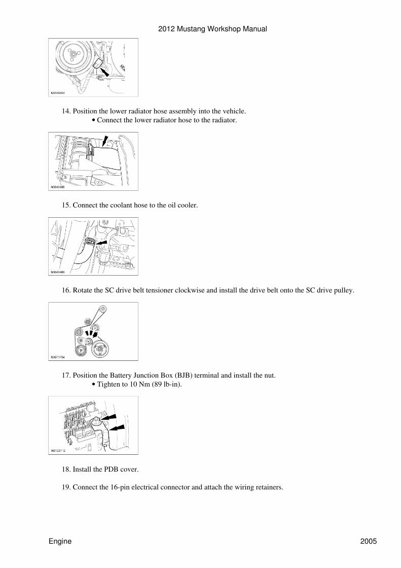
Position the lower radiator hose assembly into the vehicle.Connect the lower radiator hose to the radiator.•
14.
Connect the coolant hose to the oil cooler.15.
Rotate the SC drive belt tensioner clockwise and install the drive belt onto the SC drive pulley.16.
Position the Battery Junction Box (BJB) terminal and install the nut.Tighten to 10 Nm (89 lb-in).•
17.
Install the PDB cover.18.
Connect the 16-pin electrical connector and attach the wiring retainers.19.
2012 Mustang Workshop Manual
Engine 2005

Connect the 16-pin electrical connector and attach the 2 wiring retainers.20.
Connect the 2 PCM electrical connectors.21.
Attach the 2 wiring harness pin-type retainers.22.
Attach the pin-type wire harness retainer to the cowl.23.
Position the ground cables and install the 2 bolts.Tighten to 10 Nm (89 lb-in).•
24.
2012 Mustang Workshop Manual
Engine 2006

Connect the 2 heater hoses to the coolant tube assembly at the rear of the engine.25.
Connect the Evaporative Emission (EVAP) tube quick connect coupling and the brake boostervacuum supply tube to the Throttle Body (TB) spacer. For additional information, refer to Section310-00 .
26.
Connect the fuel supply tube. For additional information, refer to Section 310-00 .27.
Connect the coolant hose to the coolant pump.28.
Connect the coolant hose to the thermostat housing.29.
2012 Mustang Workshop Manual
Engine 2007

Connect the coolant hose to the coolant tube assembly (above the generator).30.
Connect the coolant hose to the Charge Air Cooler (CAC).31.
NOTE: RH bolt shown, LH similar.
Install the cooling fan assembly and the 2 bolts.
Tighten to 9 Nm (80 lb-in).•
32.
Position the charge air cooler hose and install the bolt.Tighten to 8 Nm (71 lb-in).•
33.
Connect the cooling fan electrical connector.34.
2012 Mustang Workshop Manual
Engine 2008

Connect the upper radiator hose from the thermostat housing.35.
Install the SC coolant degas bottle. For additional information, refer to Section 303-03B .36.
Install the engine coolant degas bottle. For additional information, refer to Section 303-03A .37.
Install the brake booster. For additional information, refer to Section 206-07 .38.
Install the battery tray and battery. For additional information, refer to Section 414-01 .39.
Install the Air Cleaner (ACL) and ACL outlet pipe. For additional information, refer to Section303-12 .
40.
Install the battery and tray. For additional information, refer to Section 414-01 .41.
NOTE: Use the hood hinge location index marks made during removal to aid in hood installation.
Install the hood and the 4 bolts.
Tighten to 12 Nm (106 lb-in).•
42.
Attach the 2 windshield washer hose retainers and connect the 2 windshield washer hose C-LockCouplers. For additional information, refer to Section 501-16 .
43.
2012 Mustang Workshop Manual
Engine 2009

Install the 2 windshield washer hose retainers and the 8 hood insulation pin-type retainers (2 shown).44.
Fill the engine with clean engine oil.45.
Fill and bleed the engine cooling system. For additional information, refer to Section 303-03A .46.
Fill and bleed the SC cooling system. For additional information, refer to Section 303-03B .47.
After completing the repairs, use the scan tool to perform the Misfire Monitor Neutral ProfileCorrection procedure, following the on-screen instructions.
48.
2012 Mustang Workshop Manual
Engine 2010
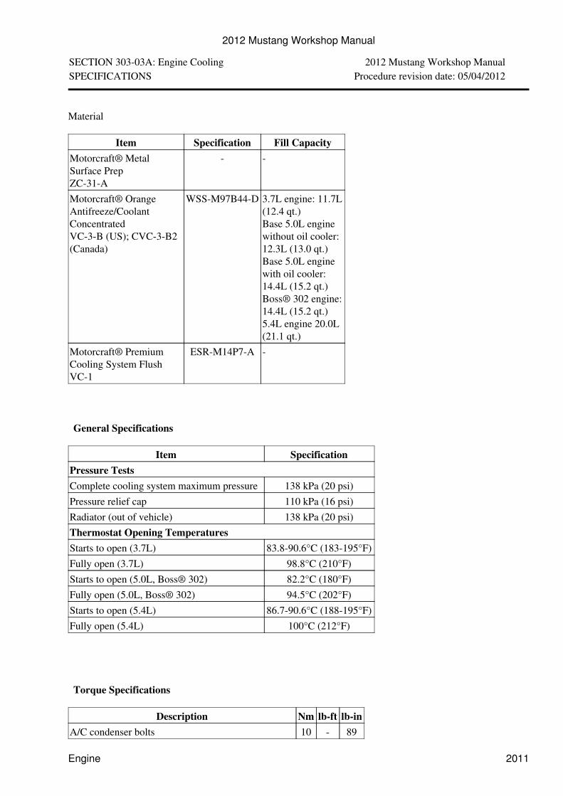
SECTION 303-03A: Engine Cooling 2012 Mustang Workshop ManualSPECIFICATIONS Procedure revision date: 05/04/2012
Material
Item Specification Fill CapacityMotorcraft® MetalSurface PrepZC-31-A
- -
Motorcraft® OrangeAntifreeze/CoolantConcentratedVC-3-B (US); CVC-3-B2(Canada)
WSS-M97B44-D 3.7L engine: 11.7L(12.4 qt.)Base 5.0L enginewithout oil cooler:12.3L (13.0 qt.)Base 5.0L enginewith oil cooler:14.4L (15.2 qt.)Boss® 302 engine:14.4L (15.2 qt.)5.4L engine 20.0L(21.1 qt.)
Motorcraft® PremiumCooling System FlushVC-1
ESR-M14P7-A -
General Specifications
Item SpecificationPressure TestsComplete cooling system maximum pressure 138 kPa (20 psi)Pressure relief cap 110 kPa (16 psi)Radiator (out of vehicle) 138 kPa (20 psi)Thermostat Opening TemperaturesStarts to open (3.7L) 83.8-90.6°C (183-195°F)Fully open (3.7L) 98.8°C (210°F)Starts to open (5.0L, Boss® 302) 82.2°C (180°F)Fully open (5.0L, Boss® 302) 94.5°C (202°F)Starts to open (5.4L) 86.7-90.6°C (188-195°F)Fully open (5.4L) 100°C (212°F)
Torque Specifications
Description Nm lb-ft lb-inA/C condenser bolts 10 - 89
2012 Mustang Workshop Manual
Engine 2011

A/C condenser nuts 8 - 71Block heater 40 30 -Charge air cooler hose bolt - 5.4L 8 - 71Coolant outlet connector bolts - 5.4L 10 - 89Coolant pump bolts - 3.7L a - - -Coolant pump bolt - 5.0L a - - -Coolant pump bolts - 5.4L 25 18 -Coolant pump pulley bolts - 3.7L 24 18 -Coolant pump pulley bolts - 5.0L a - - -Coolant pump pulley bolts - 5.4L 25 18 -Cooling fan motor and shroud bolt and stud bolt 8 - 71Degas bottle bolts 8 - 71Heater outlet tube bolt - 5.0L 10 - 89Lower splash shield bolts 5 - 44Radiator support bracket bolts 10 - 89Supercharger (SC) degas bottle bolt - 5.4L 8 - 71Thermostat housing bolts - 3.7L a - - -Thermostat housing bolts - 5.0L 10 - 89Thermostat housing nuts - 5.4L 25 18 -Transmission cooler bolts (if equipped) 8 - 71Transmission cooler tubes bracket bolt (if equipped) 7 - 62a Refer to procedure
2012 Mustang Workshop Manual
Engine 2012
SECTION 303-03A: Engine Cooling 2012 Mustang Workshop ManualDESCRIPTION AND OPERATION Procedure revision date: 01/21/2011
Engine Cooling
NOTICE: The engine cooling system is filled with Motorcraft® Specialty Orange Engine Coolant.Always fill the cooling system with the manufacturer's specified coolant. If a non-specified coolant hasbeen used the cooling system must be chemically flushed. Refer to Cooling System Flushing in thissection. Failure to follow these instructions may damage the engine or cooling system.
NOTE: During normal vehicle operation, Motorcraft® Specialty Orange Engine Coolant may change colorfrom orange to pink or light red. As long as the engine coolant is clear and uncontaminated, this color changedoes not indicate the engine coolant has degraded nor does it require the engine coolant to be drained, thesystem to be flushed, or the engine coolant to be replaced.
The cooling system components include the:
block heater (if equipped)• Cylinder Head Temperature (CHT) sensor• fan motor and shroud assembly• radiator• radiator cap• radiator draincock• coolant pump• coolant thermostat• oil filter adapter (Boss® 302 and 5.4L engine)• oil cooler (Boss® 302 and 5.4L engines)• radiator overflow hose• degas bottle• upper radiator hose• lower radiator hose• Engine Coolant Temperature (ECT) sensor (5.4L engine)•
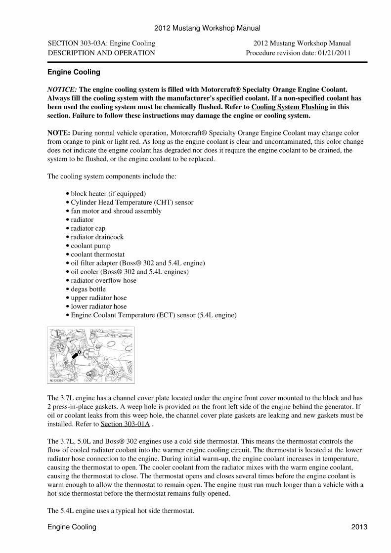
The 3.7L engine has a channel cover plate located under the engine front cover mounted to the block and has2 press-in-place gaskets. A weep hole is provided on the front left side of the engine behind the generator. Ifoil or coolant leaks from this weep hole, the channel cover plate gaskets are leaking and new gaskets must beinstalled. Refer to Section 303-01A .
The 3.7L, 5.0L and Boss® 302 engines use a cold side thermostat. This means the thermostat controls theflow of cooled radiator coolant into the warmer engine cooling circuit. The thermostat is located at the lowerradiator hose connection to the engine. During initial warm-up, the engine coolant increases in temperature,causing the thermostat to open. The cooler coolant from the radiator mixes with the warm engine coolant,causing the thermostat to close. The thermostat opens and closes several times before the engine coolant iswarm enough to allow the thermostat to remain open. The engine must run much longer than a vehicle with ahot side thermostat before the thermostat remains fully opened.
The 5.4L engine uses a typical hot side thermostat.
2012 Mustang Workshop Manual
Engine Cooling 2013

The fan motor:
operates only when the ignition switch is in the RUN position.• will not operate with the switch in the OFF position.•
Engine coolant provides boil protection, corrosion protection, freeze protection and cooling efficiency to theengine and cooling components. In order to obtain these protections, maintain the engine coolant at the correctconcentration and fluid level in the degas bottle.
When adding engine coolant, use a 50/50 mixture of engine coolant and distilled water. A coolantconcentration of 50% will provide freeze point protection down to -37°C (-34°F).
To maintain the integrity of the coolant and the cooling system:
add Motorcraft® Specialty Orange Engine Coolant or equivalent (orange color) meeting Fordspecification WSS-M97B44-D. Do not mix coolant types.
•
do not add or mix with any other engine coolant. Mixing coolants may degrade the coolant corrosionprotection.
•
do not add alcohol, methanol or brine, or any engine coolants mixed with alcohol or methanolantifreeze. These can cause engine damage from overheating or freezing.
•
Ford Motor Company does NOT recommend the use of recycled engine coolant in vehicles originallyequipped with Motorcraft® Specialty Orange Engine Coolant since a Ford-approved recyclingprocess is not yet available.
•
The optional block heater:
electrical heating element is installed in the core plug opening.• uses a standard 110V electrical supply.• keeps the engine coolant warm during cold weather.•
Coolant Flow Diagram
3.7L
NOTE: Black arrows indicate hot, white arrows indicate cold.
Item Part Number Description1 9J447 Intake manifold
2012 Mustang Workshop Manual
3.7L 2014

2 8050 LH cylinder head3 8501 Coolant pump4 8B274 Upper radiator hose5 8A586 Thermostat housing6 8075A Thermostat housing-to-degas bottle hose7 8B273 Lower radiator hose8 8005 Radiator9 8075B Radiator-to-degas bottle hose10 8A080 Degas bottle11 8K289 Coolant return hose12 18B402 Heater outlet tube13 18472B Heater outlet hose14 6010 Cylinder block15 18K579 Heater inlet hose16 18B539 Heater core17 6049 RH cylinder head
5.0L without Engine Oil Cooler
NOTE: Black arrows indicate hot, white arrows indicate cold.
Item Part Number Description1 8A080 Degas bottle2 8K276 Degas bottle-to-engine hose3 8276 Radiator-to-degas bottle hose4 8276 Coolant outlet connector-to-degas bottle hose5 18696 Heater inlet tube6 18K579 Heater inlet hose7 18K580 Heater outlet hose8 18663 Heater outlet tube9 8594 Coolant outlet connector10 18B539 Heater core
2012 Mustang Workshop Manual
5.0L without Engine Oil Cooler 2015