2011 remedial action 4501 lake otis parkway anchorage, alaska
TRANSCRIPT

2011 Remedial Action 4501 Lake Otis Parkway
Anchorage, Alaska ADEC File No. 2100.38.511
December 2011
Submitted To: Municipality of Anchorage
Real Estate Department 4700 Elmore Road
Anchorage, Alaska 99507
By: Shannon & Wilson, Inc.
5430 Fairbanks Street, Suite 3 Anchorage, Alaska 99518
Phone: 907-561-2120 FAX: 907-561-4483
32-1-17172-011

TABLE OF CONTENTS Page
2011 Remedial Action, 4501 Lake Otis Parkway, Anchorage, Alaska 32-1-17172-011 i
VOLUME I
1.0 INTRODUCTION ..................................................................................................................1
2.0 SITE AND PROJECT DESCRIPTION .................................................................................1 2.1 Site Use History .........................................................................................................1 2.2 Contaminant Sources and Constituents of Concern ...................................................1 2.3 Extent of Impacted Media ..........................................................................................2 2.4 Regulatory Requirements and Cleanup Standards .....................................................3
2.4.1 ADEC Requirements ...................................................................................3 2.4.2 Federal/EPA Requirements - RCRA ...........................................................5 2.4.3 Federal/EPA Requirements – UIC Program ................................................7
2.5 Remedial Action Objective ........................................................................................8 2.6 Summary of Alternatives Analysis and Decision Document .....................................8 2.7 Remedial Action Strategy & Scope Overview ...........................................................9
3.0 FIELD ACTIVITIES ..............................................................................................................9 3.1 Soil Screening and Sampling Methods ....................................................................10 3.2 June 2011 Buried Drum Removal ............................................................................11 3.3 Pre-Excavation Site Preparation ...............................................................................12 3.4 Soil Consolidation Area Preparation ........................................................................13 3.5 Souce-Area Excavation and Soil Consolidation ......................................................14 3.6 Buried Debris Removal ............................................................................................15
3.6.1 Cottonwood Tree Roots .............................................................................16 3.6.2 Dry Well.....................................................................................................16 3.6.3 Log Crib .....................................................................................................16 3.6.4 Buried Process Tank ..................................................................................17 3.6.5 Pipes ...........................................................................................................17
3.7 Baseline Soil Samples ..............................................................................................18 3.8 Excavation Backfill and Oxidant Application .........................................................19 3.9 Passive Remediation System Installation .................................................................20 3.10 Drinking Water Well Search ....................................................................................21 3.11 Surveying .................................................................................................................21 3.12 Site Health & Safety Measures ................................................................................21
4.0 LABORATORY ANALYSIS ..............................................................................................22
5.0 SUBSURFACE CONDITIONS ...........................................................................................23
6.0 DISCUSSION OF RESULTS ..............................................................................................24 6.1 Drum Area Samples .................................................................................................24 6.2 Baseline Soil Samples ..............................................................................................24 6.3 Excavation Samples .................................................................................................26 6.4 Debris Characterization Samples .............................................................................26
TABLE OF CONTENTS Page
2011 Remediation Activities, 4501 Lake Otis Parkway, Anchorage, Alaska 32-1-17172-011 ii
6.5 Air Monitoring Samples ...........................................................................................27 6.6 Quality Assurance Samples ......................................................................................27
7.0 INVESTIGATION DERIVED WASTE ..............................................................................29
8.0 CONCEPTUAL SITE MODEL ...........................................................................................30 8.1 Soil Direct Contact ...................................................................................................31 8.2 Groundwater Ingestion .............................................................................................31 8.3 Outdoor Air Inhalation .............................................................................................32 8.4 Indoor Air Inhalation / Vapor Intrusion ...................................................................32 8.5 Surface Water ...........................................................................................................32 8.6 Other .........................................................................................................................32 8.7 CSM Summary .........................................................................................................33
9.0 SUMMARY .........................................................................................................................33
10.0 CLOSURE/LIMITATIONS .................................................................................................34
TABLES
1 Sample Locations and Descriptions 2 Summary of Drum Area Soil Sample Analytical Results 3 Summary of Drum Liquid Sample Analytical Results 4 Summary of Consolidation Area and Excavation Soil Sample Analytical Results 5 Summary of Disposal Characterization Sample Analytical Results
FIGURES
1 Site Plan 2 Drum Area Sample Locations 3 Source-Area Excavation Sample Locations 4 Consolidation Area Sample Locations 5 In-Situ Treatment System – Plan View 6 In-Situ Treatment System – Profiles
VOLUME II - APPENDICES
A Site Photographs B Results of Analytical Testing By SGS North America Inc. of Anchorage, Alaska
and ADEC Laboratory Data Review Checklists C Geotextile Specification Sheet D Results of Site Survey by Del Norte Surveying, Inc. E Conceptual Site Model F Important Information About Your Geotechnical/Environmental Report
ACRONYMS AND ABBREVIATIONS
2011 Remedial Action, 4501 Lake Otis Parkway, Anchorage, Alaska 32-1-17172-011 iii
AAC Alaska Administrative Code
ABCA Analysis of Brownfields Cleanup Objectives ADEC Alaska Department of Environmental Conservation
AK Alaska Method AOC Area of Contamination BCX B.C. Excavating
bgs below ground surface BTEX benzene, toluene, ethylbenzene, and xylenes
CFR Code of Federal Regulations COC Compound of concern
COPC Contaminant of potential concern CSM Conceptual Site Model
cy Cubic yard DCE Dichloroethene DRO Diesel range organics DQO Data quality objective EPA Environmental Protection Agency GRO Gasoline range organics ICRT Interim concentration reduction threshold LDR Land disposal restrictions
LSC/LCSD Laboratory control sample/laboratory control sample duplicate LOD Limit of detection LOQ Limit of quantitation
mg/kg Milligrams per kilogram mg/L Milligrams per liter
ml milliliters MOA Municipality of Anchorage
MS/MSD Matrix spike/matrix spike duplicate MTG Migration to groundwater NCP National Oil and Hazardous Substances Pollution Contingency Plan PAH Polyaromatic hydrocarbons PCE Tetrachloroethene PEL Permissible Exposure Limit PID Photoionization detector PPE Personal protective equipment ppm Parts per million

ACRONYMS AND ABBREVIATIONS
2011 Remedial Action, 4501 Lake Otis Parkway, Anchorage, Alaska 32-1-17172-011 iv
ppmv Parts per million by volume PVC Polyvinyl chloride
QAPP Quality Assurance Project Plan QA/QC Quality assurance/ quality control
RA Remedial Action RAO Remedial Action Objective
RCRA Resource Conservation and Recovery Act RPD Relative percent difference RRO Residual range organics
SF Square feet SGS SGS North America Inc.
SSH&SP Site Specific Health and Safety Plan STEL Short Term Exposure Limit TCE Trichloroethene
TCLP Toxic Characteristic Leaching Procedure µg/kg Micrograms per kilogram UIC Underground injection control UST Underground storage tank UTS Universal treatment standard VC Vinyl chloride
VES Vapor extraction system VI Vapor intrusion
VOC Volatile organic compounds
2011 REMEDIAL ACTION 4501 LAKE OTIS PARKWAY
ANCHORAGE, ALASKA ADEC FILE NO. 2100.38.511
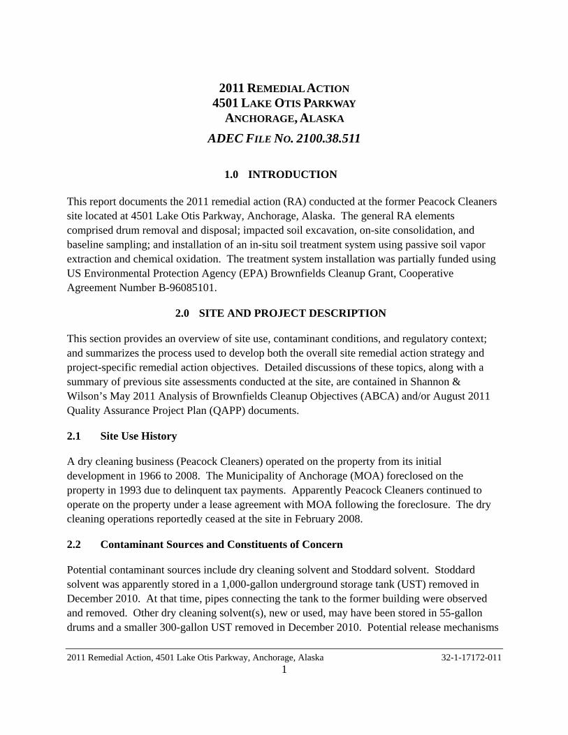
1.0 INTRODUCTION
This report documents the 2011 remedial action (RA) conducted at the former Peacock Cleaners site located at 4501 Lake Otis Parkway, Anchorage, Alaska. The general RA elements comprised drum removal and disposal; impacted soil excavation, on-site consolidation, and baseline sampling; and installation of an in-situ soil treatment system using passive soil vapor extraction and chemical oxidation. The treatment system installation was partially funded using US Environmental Protection Agency (EPA) Brownfields Cleanup Grant, Cooperative Agreement Number B-96085101.
2.0 SITE AND PROJECT DESCRIPTION
This section provides an overview of site use, contaminant conditions, and regulatory context; and summarizes the process used to develop both the overall site remedial action strategy and project-specific remedial action objectives. Detailed discussions of these topics, along with a summary of previous site assessments conducted at the site, are contained in Shannon & Wilson’s May 2011 Analysis of Brownfields Cleanup Objectives (ABCA) and/or August 2011 Quality Assurance Project Plan (QAPP) documents.
2.1 Site Use History
A dry cleaning business (Peacock Cleaners) operated on the property from its initial development in 1966 to 2008. The Municipality of Anchorage (MOA) foreclosed on the property in 1993 due to delinquent tax payments. Apparently Peacock Cleaners continued to operate on the property under a lease agreement with MOA following the foreclosure. The dry cleaning operations reportedly ceased at the site in February 2008.
2.2 Contaminant Sources and Constituents of Concern
Potential contaminant sources include dry cleaning solvent and Stoddard solvent. Stoddard solvent was apparently stored in a 1,000-gallon underground storage tank (UST) removed in December 2010. At that time, pipes connecting the tank to the former building were observed and removed. Other dry cleaning solvent(s), new or used, may have been stored in 55-gallon drums and a smaller 300-gallon UST removed in December 2010. Potential release mechanisms
2011 Remedial Action, 4501 Lake Otis Parkway, Anchorage, Alaska 32-1-17172-011 1
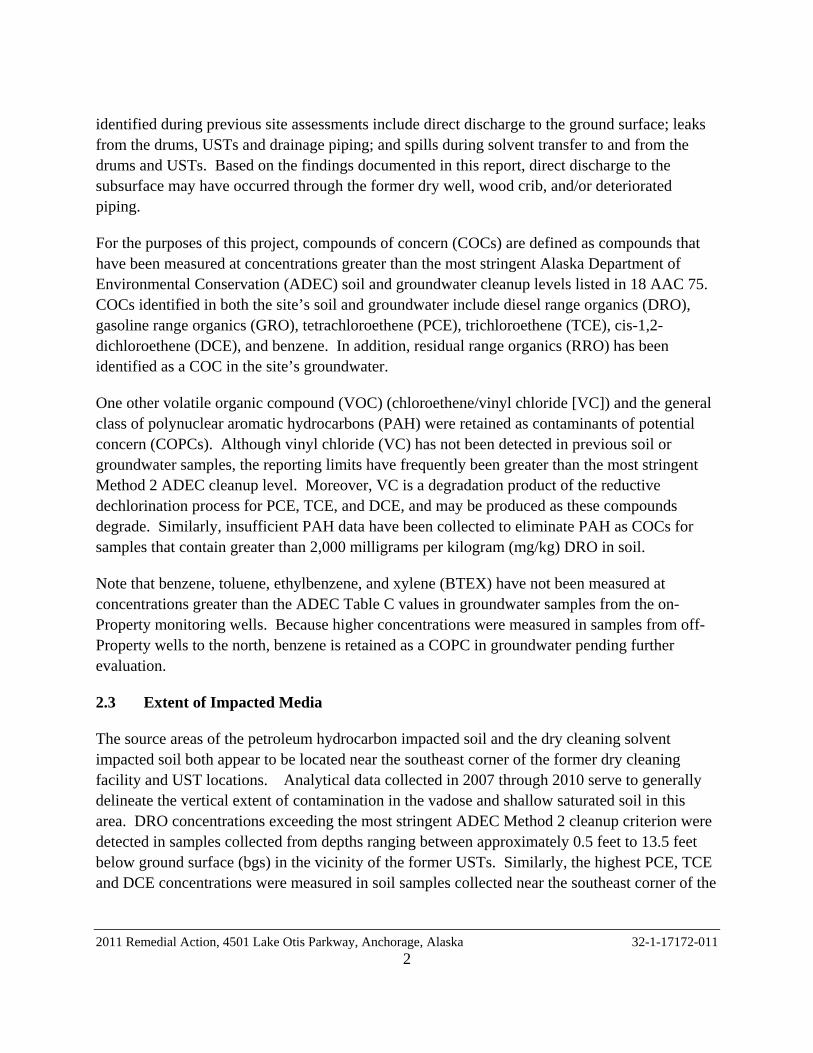
identified during previous site assessments include direct discharge to the ground surface; leaks from the drums, USTs and drainage piping; and spills during solvent transfer to and from the drums and USTs. Based on the findings documented in this report, direct discharge to the subsurface may have occurred through the former dry well, wood crib, and/or deteriorated piping.
For the purposes of this project, compounds of concern (COCs) are defined as compounds that have been measured at concentrations greater than the most stringent Alaska Department of Environmental Conservation (ADEC) soil and groundwater cleanup levels listed in 18 AAC 75. COCs identified in both the site’s soil and groundwater include diesel range organics (DRO), gasoline range organics (GRO), tetrachloroethene (PCE), trichloroethene (TCE), cis-1,2-dichloroethene (DCE), and benzene. In addition, residual range organics (RRO) has been identified as a COC in the site’s groundwater.
One other volatile organic compound (VOC) (chloroethene/vinyl chloride [VC]) and the general class of polynuclear aromatic hydrocarbons (PAH) were retained as contaminants of potential concern (COPCs). Although vinyl chloride (VC) has not been detected in previous soil or groundwater samples, the reporting limits have frequently been greater than the most stringent Method 2 ADEC cleanup level. Moreover, VC is a degradation product of the reductive dechlorination process for PCE, TCE, and DCE, and may be produced as these compounds degrade. Similarly, insufficient PAH data have been collected to eliminate PAH as COCs for samples that contain greater than 2,000 milligrams per kilogram (mg/kg) DRO in soil.
Note that benzene, toluene, ethylbenzene, and xylene (BTEX) have not been measured at concentrations greater than the ADEC Table C values in groundwater samples from the on-Property monitoring wells. Because higher concentrations were measured in samples from off-Property wells to the north, benzene is retained as a COPC in groundwater pending further evaluation.
2.3 Extent of Impacted Media
The source areas of the petroleum hydrocarbon impacted soil and the dry cleaning solvent impacted soil both appear to be located near the southeast corner of the former dry cleaning facility and UST locations. Analytical data collected in 2007 through 2010 serve to generally delineate the vertical extent of contamination in the vadose and shallow saturated soil in this area. DRO concentrations exceeding the most stringent ADEC Method 2 cleanup criterion were detected in samples collected from depths ranging between approximately 0.5 feet to 13.5 feet below ground surface (bgs) in the vicinity of the former USTs. Similarly, the highest PCE, TCE and DCE concentrations were measured in soil samples collected near the southeast corner of the
2011 Remedial Action, 4501 Lake Otis Parkway, Anchorage, Alaska 32-1-17172-011 2

former Peacock Cleaners building and in the vicinity of the former USTs and a drain pipe exiting the building. The elevated PCE and TCE concentrations extend from 0.5 to 20 feet bgs in this area, with the concentrations of PCE increasing from near the ground surface to 8 to 9 feet bgs, and then decreasing with depth. In contrast, DCE was also detected at a concentration exceeding ADEC cleanup criteria in soil samples collected between 12 and 16 feet bgs.
The lateral extent and distribution of petroleum hydrocarbon (Stoddard solvent)-impacted media appears to differ from that of the other solvent-impacted media, presumably due to different release events and contaminant fate and transport mechanisms. However, the RA documented in this report was intended to address the most highly-impacted soils comprising both the Stoddard Solvent and chlorinated solvent source area(s).
2.4 Regulatory Requirements and Cleanup Standards
The site cleanup operations are subject to regulation by both state and federal agencies. The governing agency for cleanup of contaminated sites in Alaska is the ADEC. Certain elements of the project also entailed involvement of two separate EPA programs. The EPA Region 10 Resource Conservation and Recovery Act (RCRA) Hazardous Waste Program was consulted to identify the appropriate hazardous waste characterization, cleanup, and disposal criteria, and to otherwise clarify RCRA applicability to the site. The EPA Region 10 Underground Injection Control (UIC) Program was contacted to discuss the regulatory status of the concrete dry well discovered during the RA implementation. The site has been assigned EPA identification number AKR 00020 2747.
2.4.1 ADEC Requirements
Site cleanup activities were conducted under the State of Alaska Oil and Other Hazardous Substances Pollution Control regulations (18 Alaska Administrative Code [AAC] 75). The ADEC cleanup standards promulgated under 18 AAC 75 are risk-based standards associated with several different exposure routes. The cleanup levels are generally applied to evaluate regulatory compliance and site closure eligibility. For this project, the cleanup levels will also be applied to a more directed application of assessing the level of media-specific concentration reduction needed to support different types of future land uses and to protect specific receptors and exposure routes.
The ADEC cleanup standards for individual chemicals in soil are based on the Method 2 cleanup levels listed in Tables B1 and B2, 18 AAC 75.341, for the “under-40-inches precipitation zone.” Discrete soil cleanup levels are provided for the “Direct Contact,” “Outdoor Inhalation,” and “Migration to Groundwater” exposure pathways. The direct contact and outdoor inhalation concentrations must be attained in the surface and subsurface soil to a depth of at least 15 feet,
2011 Remedial Action, 4501 Lake Otis Parkway, Anchorage, Alaska 32-1-17172-011 3

unless an institutional control or site conditions eliminate potential for exposure. In addition, cleanup to the most stringent Method 2 standard – typically the migration to groundwater standard - is normally required by ADEC for a cleanup complete (without institutional controls) determination. Cleanup standards for groundwater are the ADEC groundwater cleanup levels listed in Table C, 18 AAC 75.345.
Reducing the contaminant concentrations to meet the ADEC cleanup criteria for unconditional closure is likely not attainable due to funding constraints, coupled with contaminant mass and distribution characteristics. To achieve project objectives, the RA is instead focused on achieving interim concentration reduction thresholds (ICRT) following the prioritized exposure pathway mitigation approach outlined in Section 2.5. The threshold levels selected to be protective of immediate threats to human health and the environment are equivalent to the ADEC direct contact or outdoor inhalation soil cleanup levels, whichever is most restrictive. The ICRT values are not presented as cleanup levels for closure purposes, but may comprise the minimum level of cleanup acceptable to ADEC for property re-use. Impacted media containing residual concentrations greater than the most stringent ADEC cleanup criteria will remain subject to ADEC regulation.
SUMMARY OF APPLICABLE ADEC CLEANUP LEVELS SOIL*
(ADEC Method 2) GROUNDWATER
(ADEC Table C)
COC Direct Contact Outdoor Inhalation
Migration to Groundwater
GRO 1,400 mg/kg 1,400 mg/kg 300 mg/kg 2.2 mg/L
DRO 10,250 mg/kg 12,500 mg/kg 250 mg/kg 1.5 mg/L
RRO 10,000 mg/kg 22,000 mg/kg 11,000 mg/kg 1.1 mg/L
Benzene 150,000 µg/kg 11,000 µg/kg 25 µg/kg 5 µg/L
PCE 15,000 µg/kg 10,000 µg/kg 24 µg/kg 5 µg/L
TCE 21,000 µg/kg 570 µg/kg 20 µg/kg 5 µg/L
DCE 1x10⁶ µg/kg 130,000 µg/kg 240 µg/kg 70 µg/L
VC 5,500 µg/kg 4,300 µg/kg 8.5 µg/kg 2 µg/L
PAH For individual PAH compounds, see Table B1, 18 AAC 75.341 for soil cleanup levels and Table C, 18 AAC 75.345 for groundwater cleanup levels
* Project-specific concentration reduction thresholds (ICRT) are highlighted in blue
2011 Remedial Action, 4501 Lake Otis Parkway, Anchorage, Alaska 32-1-17172-011 4
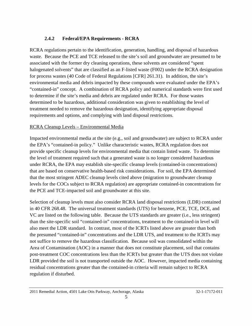
2.4.2 Federal/EPA Requirements - RCRA
RCRA regulations pertain to the identification, generation, handling, and disposal of hazardous waste. Because the PCE and TCE released to the site’s soil and groundwater are presumed to be associated with the former dry cleaning operations, these solvents are considered “spent halogenated solvents” that are classified as an F-listed waste (F002) under the RCRA designation for process wastes (40 Code of Federal Regulations [CFR] 261.31). In addition, the site’s environmental media and debris impacted by these compounds were evaluated under the EPA’s “contained-in” concept. A combination of RCRA policy and numerical standards were first used to determine if the site’s media and debris are regulated under RCRA. For those wastes determined to be hazardous, additional consideration was given to establishing the level of treatment needed to remove the hazardous designation, identifying appropriate disposal requirements and options, and complying with land disposal restrictions.
RCRA Cleanup Levels – Environmental Media
Impacted environmental media at the site (e.g., soil and groundwater) are subject to RCRA under the EPA’s “contained-in policy.” Unlike characteristic wastes, RCRA regulation does not provide specific cleanup levels for environmental media that contain listed waste. To determine the level of treatment required such that a generated waste is no longer considered hazardous under RCRA, the EPA may establish site-specific cleanup levels (contained-in concentrations) that are based on conservative health-based risk considerations. For soil, the EPA determined that the most stringent ADEC cleanup levels cited above (migration to groundwater cleanup levels for the COCs subject to RCRA regulation) are appropriate contained-in concentrations for the PCE and TCE-impacted soil and groundwater at this site.
Selection of cleanup levels must also consider RCRA land disposal restrictions (LDR) contained in 40 CFR 268.48. The universal treatment standards (UTS) for benzene, PCE, TCE, DCE, and VC are listed on the following table. Because the UTS standards are greater (i.e., less stringent) than the site-specific soil “contained-in” concentrations, treatment to the contained-in level will also meet the LDR standard. In contrast, most of the ICRTs listed above are greater than both the presumed “contained-in” concentrations and the LDR UTS, and treatment to the ICRTs may not suffice to remove the hazardous classification. Because soil was consolidated within the Area of Contamination (AOC) in a manner that does not constitute placement, soil that contains post-treatment COC concentrations less than the ICRTs but greater than the UTS does not violate LDR provided the soil is not transported outside the AOC. However, impacted media containing residual concentrations greater than the contained-in criteria will remain subject to RCRA regulation if disturbed.
2011 Remedial Action, 4501 Lake Otis Parkway, Anchorage, Alaska 32-1-17172-011 5
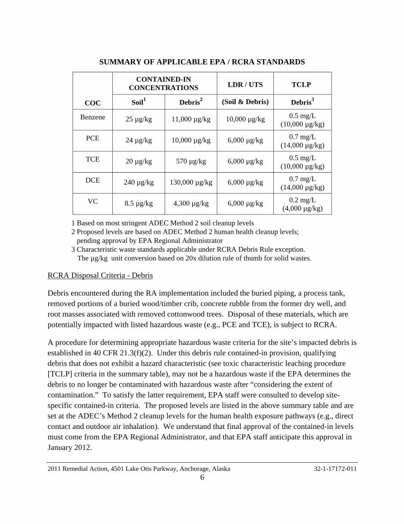
SUMMARY OF APPLICABLE EPA / RCRA STANDARDS
CONTAINED-IN CONCENTRATIONS LDR / UTS TCLP
COC Soil1 Debris2 (Soil & Debris) Debris3
Benzene 25 µg/kg 11,000 µg/kg 10,000 µg/kg 0.5 mg/L (10,000 µg/kg)
PCE 24 µg/kg 10,000 µg/kg 6,000 µg/kg 0.7 mg/L (14,000 µg/kg)
TCE 20 µg/kg 570 µg/kg 6,000 µg/kg 0.5 mg/L (10,000 µg/kg)
DCE 240 µg/kg 130,000 µg/kg 6,000 µg/kg 0.7 mg/L (14,000 µg/kg)
VC 8.5 µg/kg 4,300 µg/kg 6,000 µg/kg 0.2 mg/L (4,000 µg/kg)
1 Based on most stringent ADEC Method 2 soil cleanup levels 2 Proposed levels are based on ADEC Method 2 human health cleanup levels; pending approval by EPA Regional Administrator 3 Characteristic waste standards applicable under RCRA Debris Rule exception.
The µg/kg unit conversion based on 20x dilution rule of thumb for solid wastes.
RCRA Disposal Criteria - Debris
Debris encountered during the RA implementation included the buried piping, a process tank, removed portions of a buried wood/timber crib, concrete rubble from the former dry well, and root masses associated with removed cottonwood trees. Disposal of these materials, which are potentially impacted with listed hazardous waste (e.g., PCE and TCE), is subject to RCRA.
A procedure for determining appropriate hazardous waste criteria for the site’s impacted debris is established in 40 CFR 21.3(f)(2). Under this debris rule contained-in provision, qualifying debris that does not exhibit a hazard characteristic (see toxic characteristic leaching procedure [TCLP] criteria in the summary table), may not be a hazardous waste if the EPA determines the debris to no longer be contaminated with hazardous waste after “considering the extent of contamination.” To satisfy the latter requirement, EPA staff were consulted to develop site-specific contained-in criteria. The proposed levels are listed in the above summary table and are set at the ADEC’s Method 2 cleanup levels for the human health exposure pathways (e.g., direct contact and outdoor air inhalation). We understand that final approval of the contained-in levels must come from the EPA Regional Administrator, and that EPA staff anticipate this approval in January 2012.
2011 Remedial Action, 4501 Lake Otis Parkway, Anchorage, Alaska 32-1-17172-011 6
In addition to the TCLP and contained in requirements, the debris is also subject to LDR if it is to be disposed to the ground. By inspection of the EPA Standards Summary table, it is evident that the LDR standard is the most stringent of the three considerations for three of the five listed COCs, and thus the limiting threshold for debris disposal as a non-hazardous waste for these materials.
Application of Area of Contamination (AOC) Policy
The AOC policy facilitates streamlined remediation by allowing for movement of regulated media within defined areas of generally dispersed contamination without being considered “placement” that is subject to LDR, landfill permitting, and/or other RCRA requirements associated with conventional hazardous waste management units. The AOC policy was first applied to the site during the 2010 interim removal actions, to conduct on-site consolidation and subsequent backfill of soil removed from the UST excavation. In their November 9, 2010 letter, the EPA documented their finding that the proposed application to the Peacock Cleaners site is consistent with the policy outlined in the preamble to the National Oil and Hazardous Substances Pollution Contingency Plan (NCP) [53 FR 5144 and 55 FR 8758], and the EPA’s March 13, 1996 memo “Use of the Area of Contaminant Concept during RCRA Cleanups.” The decision was issued with the expectation that the MOA was to continue progress toward overall site cleanup, and that the AOC policy could be applied to the soil consolidation and in-situ remediation activities described in this report.
For the RA effort documented in this report, the AOC policy was applied to excavated soils that would normally be subject to RCRA regulations pertaining to containerization, treatment time, and other permitting requirements for accumulated waste. Specifically, the policy was used to conduct on-site soil consolidation as part of the in-situ remediation system construction. Additional information regarding the use and limitations of the AOC policy, and how it was applied to the subject site, is provided in the project QAPP.
2.4.3 Federal/EPA Requirements – UIC Program
The concrete dry well encountered during the RA implementation was constructed with a subsurface discharge potential at or below the water table, and is therefore considered a Class V injection well. The EPA Region 10 UIC Program was contacted by Terri Griffith regarding the regulatory status and administrative closure requirements. The EPA determined that because the dry well was being removed and the surrounding soil was being characterized and/or treated as part of the larger RA action, additional notification and planning documents for UIC closure were not required. Moreover, this report will be provided to the EPA to satisfy post-closure reporting requirements. The EPA’s determination was communicated to the project team in a September 6, 2011 email.
2011 Remedial Action, 4501 Lake Otis Parkway, Anchorage, Alaska 32-1-17172-011 7

2.5 Remedial Action Objective
The general purpose of the Brownfields program is to enable reuse/redevelopment of environmentally contaminated sites. For the former Peacock Cleaners site, funding constraints and the site’s contamination characteristics dictate that a “Cleanup Complete” determination for unrestricted land use is not practicable as a result of this RA. Moreover, the limited land use(s) that can be potentially achieved at the site, singularly through the grant-funded cleanup effort, will need to be compatible with continued ADEC regulation as an active contaminated site, including institutional controls.
In this context, the MOA’s short-term cleanup objective is to obtain a beneficial reuse while making material progress toward eventual site closure and/or iteratively less-restrictive controls on allowable land uses. This phased approach is founded on prioritized mitigation of discrete human health exposure pathways. Based on groundwater samples collected from off-Property monitoring wells, it appears that the impacted groundwater plume does not pose an imminent threat to human or ecological receptors. Therefore, the project-specific remedial action objective (RAO) was source area soil treatment to decrease the COC levels in soil to less than the concentration reduction thresholds for direct contact with soil (ingestion, dermal contact, and fugitive dust) and outdoor air inhalation. Other complete or potentially completed exposure pathways, such as groundwater ingestion/dermal contact, or indoor air vapor intrusion, are not directly targeted by the present cleanup effort, although effective source area concentration reduction will likely result in beneficial risk reduction for these exposure pathways as a secondary effect.
2.6 Summary of Alternatives Analysis and Decision Document
The May 2011 ABCA presented an analysis of seven cleanup alternatives that vary in the extent of contaminated soil and groundwater treatment. The seven cleanup alternatives were selected based on a pre-screening for applicability to the site and general effectiveness for the site-specific COCs and impacted media, with a focus on source-area soil treatment, effectiveness in treating chlorinated solvents, sustainability, and limiting institutional controls. Each alternative was evaluated using effectiveness, implementability, and cost criteria. The cost criterion considered both the short-term/capital cost to install/implement the alternative, and long-term costs for system operation, monitoring, maintenance, groundwater monitoring, and other tasks that will not be funded using the Brownfields grant (excluded costs).
The recommended alternative presented in the ABCA was In-Situ Passive Soil Vapor Extraction System (VES) and Chemical Oxidation. This alternative was found to provide the best balance of short-term and long-term treatment potential, cost effectiveness for unit mass reduction, and
2011 Remedial Action, 4501 Lake Otis Parkway, Anchorage, Alaska 32-1-17172-011 8
ability to fully implement the alternative within the grant timeline and funding constraints. The RAO will be achieved through a combination of chemical transformation (oxidation) and physical removal (VES) to reduce contaminant mass, mobility, and toxicity. An indirect benefit of groundwater cleanup will also be gained by reducing the capacity of the source-area soil to serve as a secondary source for continued groundwater contamination.
Once the cleanup effects have been confirmed, the property may be useable for redevelopment with permanent structures, even though PCE-impacted soil with concentrations exceeding the most stringent cleanup levels will likely remain on site. Vapor intrusion from remaining VOC-impacted soil and groundwater will need to be considered in the design of on-Property structures, and to assess potential impact to current/future off-site structures. In addition, soil disturbed during future Property development will remain subject to RCRA regulation.
The ABCA document was reviewed by the EPA and ADEC and was posted for 30-day public review in late May 2011. The MOA submitted a Decision Document to the EPA and ADEC on July 1, 2011 (MOA, 2011).
2.7 Remedial Action Strategy & Scope Overview
The purpose of the current project is to pursue MOA’s short-term cleanup objective and project-specific RAO by implementing the recommendation presented in the May 2011 ABCA and formalized in the July 2011 Decision Document. The primary elements of this RA are soil excavation and on-site consolidation, baseline soil sampling, installation of the in-situ vapor extraction and chemical oxidant treatment system, and reporting.
Additional work tasks that were specified in the QAPP but have not been conducted include progress/confirmation sampling and replacement of Monitoring Well B2MW. These activities are presently slated for the spring of 2012. In addition, the ADEC has communicated the need to address vapor intrusion potential and other site characterization gaps prior to site development.
3.0 FIELD ACTIVITIES
The primary RA field activity was installation of an in-situ remedial system to treat the most heavily impacted, source-area soil. In addition, this report documents a drum exploration and removal conducted in June 2011, and the discovery and partial removal of buried debris encountered during the treatment system installation. Field activities for the treatment system installation were conducted in material accordance with the August 2011 QAPP, which was approved by the EPA in an August 24, 2011 email, and by the ADEC in an August 26, 2011 conditional approval letter. The June 2011 drum removal was conducted in material accordance
2011 Remedial Action, 4501 Lake Otis Parkway, Anchorage, Alaska 32-1-17172-011 9

with Shannon & Wilson’s November 2010 Interim Removal Action Work Plan, which was conditionally approved by the ADEC in a November 19, 2010 letter.
Shannon & Wilson Inc. was retained by the MOA to serve the Environmental Consultant role identified in the QAPP. Field tasks conducted in this role included monitoring the soil excavation, on-site soil consolidation, and treatment system installation; collecting soil and waste characterization samples; and coordinating waste disposal efforts. Services subcontracted by Shannon & Wilson included fixed-laboratory chemical testing by SGS North America Inc., and surveying by Del Norte Surveying Inc. Construction services, including earthwork and remediation system installation, were provided by BC Excavating under contract to MOA.
3.1 Soil Screening and Sampling Methods
Soil Screening
Soil samples collected in the field were visually classified and “screened” for VOCs. The screening instrument was a hand-held OVM 580B photoionization detector (PID) detector that was calibrated daily using a 100-parts per million (ppm) isobutylene-in-air gas standard. Two different screening methods were employed for the project – a direct screening method and an ADEC-approved headspace method. The soil sample locations, screening results, and soil classifications are summarized in Table 1.
Direct screening was used during excavation activities to segregate soils for on-site consolidation, and entailed collecting data from the soil while it was still in the excavator bucket. PID readings were obtained by inserting the instrument probe tip in a shallow hole made in the soil with a spoon.
Headspace screening was conducted as part of the drum removal confirmation sampling, excavation characterization sampling, and consolidated soil baseline sampling. In accordance with this method, screening samples were collected using stainless steel spoons to transfer soil to re-sealable plastic bags. These samples were warmed to a common temperature and tested within 1 hour of sample collection. The screening process consists of agitating the sample bag, inserting the PID probe into the bag, and recording the maximum concentration reading. The sample locations, screening results, and soil classifications are summarized in Table 1.
Analytical Sample Collection
Characterization of COC concentrations in soil was conducted using both grab and composite samples. Grab samples were collected using a clean stainless steel spatula to place soil in
2011 Remedial Action, 4501 Lake Otis Parkway, Anchorage, Alaska 32-1-17172-011 10
laboratory-provided sample containers. The containers were filled in order of decreasing volatility; the jar(s) for volatile analytes (e.g., GRO, VOCs) were collected first, headspace samples collected second, and jars for non-volatile analytes (e.g., DRO, PAHs) last. Samples for VOC analysis were collected and field-preserved in accordance with Alaska Method (AK) 101 and EPA Method 8260B requirements. To prevent leakage, the rim of each sample container was quickly wiped free of soil particles with a piece of clean paper towel before capping.
Composite soil samples were collected by combining an approximately equal mass of soil from five discrete sample locations using a clean stainless steel spatula. The spatula was calibrated by Shannon & Wilson in the field using a portable scale. The calibration procedure consisted of weighing 10 grams of various site soils and placing the soil on the spatula to obtain visual estimates of the corresponding volumes. Sample collection entailed placing each of the five portions into laboratory-provided containers. Methanol was added to the sample container for VOC analysis immediately following placement of the first individual soil portion. Subsequent portions were added using care to avoid splashing the methanol and to minimize the time the cap was open.
Composite samples for debris media were collected using the same general protocol, with media-specific variations discussed Section 3.6.
3.2 June 2011 Buried Drum Removal
A drum removal effort was conducted on June 9, 2011, to complete the preliminary remedial tasks identified in the draft ABCA. The drum removal was conducted at the southeast portion of the property, where partially buried drums had been identified during Shannon and Wilson Inc.’s 2007 site characterization. To locate the drums, B.C. Excavating (BCX) removed surface soils and vegetation to a depth of about 1 foot using an excavator. Scrap piping and metal debris observed in the removed soil were extracted to the extent practicable and set aside. Following the surface soil removal, a sweep of the area was conducted with a Schonstedt metal detector to locate additional drums. However, the metal detector sweep was not effective due to the presence of additional small metal debris (e.g. nails, small pieces of pipe) that could not be easily removed from the in-place soil.
Three drums, steel pipes, and other debris were located. One 55-gallon drum (Drum 1) contained approximately 10 gallons of liquid. This drum was placed in an overpack drum until the means of disposal could be determined. One 55-gallon drum (Drum 3) and one 25-gallon drum (Drum 2) were found empty. The approximate locations of the drums are shown on Figure 2, and photos depicting the location and removal of Drum 1 are included as Photos 1 and 2 in Appendix A.
2011 Remedial Action, 4501 Lake Otis Parkway, Anchorage, Alaska 32-1-17172-011 11

Three screening soil samples were collected from the soil beneath each former drum location. Each sample was visually classified and screened using the headspace sampling method. Based on field screening results, one analytical sample was collected from soil below each former drum location. In addition, one duplicate sample was collected from beneath Drum 3, and a disposal characterization sample was collected from the liquid contents of Drum 1.
Following the drum removal, the scraped soil was replaced and leveled to restore the surface. Debris and piping that were removed during the earthwork were placed on the ground surface adjacent to the north edge of the assessed area near Monitoring Well B5MW. Surface vegetation that was removed during the drum removal effort was spread over the restored surface.
3.3 Pre-Excavation Site Preparation
Prior to excavation, the local utility locate services identified buried utilities on the property. Shannon & Wilson’s field representative marked the target treatment cell boundaries using surveyors lathe. The excavation location and dimensions were selected to create a cell capable of treating 600 cubic yards (cy) of the most contaminated chlorinated solvent and Stoddard Solvent (DRO) impacted soil. The volume was calculated using previous site characterization, with the intent of capturing the bulk of soils containing PCE concentrations greater than the 10,000 micrograms per kilogram (µg/kg) ICRT. Landmarks used to establish the treatment cell location within the inferred source area include the 2010 UST excavation boundaries, existing monitoring wells, and GPS measurements of previous soil boring locations. The treatment cell location relative to these site features is shown on Figure 1.
To facilitate equipment access, BCX cleared and leveled the area near the north gate to improve vehicular access. Additional clean gravel was imported from off site and placed near the entrance to improve the driving surface. During the clearing and leveling efforts, BCX encountered an apparent flush-mount protective well casing embedded in concrete near the north gate. The protective monument is presumed to be from Monitoring Well MW16, which was not located during the December 2010 groundwater sampling event. The monument was found 30 feet east of the Monitoring Well MW16 location shown in previous site characterization reports. The protective monument appeared to have been damaged or disturbed, and it was not immediately evident whether the monument had been moved from the Monitoring Well MW16 location, or if the well casing was intact beneath the current monument location. The approximate location of the monument is shown on Figure 1 and in Photo 3. A cone was placed over the monument to prevent additional damage.
2011 Remedial Action, 4501 Lake Otis Parkway, Anchorage, Alaska 32-1-17172-011 12
3.4 Soil Consolidation Area Preparation
Although the remediation system is designed to treat approximately 600 cy, additional soil removal/consolidation was required due to excavation layback, potentially clean overburden above the treatment cell, accounting for the volume to be occupied by subsurface VES materials, and the focused additional soil removal from the excavation’s southeast corner. Based on the preliminary design dimensions, it was estimated that the consolidation areas would need to be capable of handling at least 1,100 cy. Note that it was important to allow for all excavated soil to be consolidated before backfilling, as the excavation needed to be completed before determining which portion of the consolidated soil was replaced in the treatment cell.
Two general consolidation areas were prepared; these areas are identified as the North Consolidation Area and Northeast Consolidation Area on Figure 1. BCX cleared, grubbed, and leveled the former residence building footprint and the area surrounding the proposed treatment cell to facilitate equipment access to these areas and to obtain a level working surface. The grubbed material, which included topsoil organics, grass, and brush, was temporarily placed on site south of the former residence building footprint.
A 12 mil petroleum-resistant liner was placed on the surface of each consolidation area prior to soil placement. Materials that could potentially damage the liner (i.e oversize rocks, concrete or woody organics) were separated from the excavated soil placed in the consolidation area and were placed in debris piles west of the partially buried drum storage area. These materials were eventually incorporated into the backfill or other waste streams discussed in Section 7.0, as appropriate. Berms were constructed around the north consolidation area using excavated soils that screened clean (i.e., less than 1 part per million [ppm] using the screening process described in Section 3.3).
Nearby on-Property Monitoring Wells B1MW and B4MW that were not within the treatment cell footprint were marked with orange cones to avoid damage during the construction activities. To reduce the potential for off-Property sediment transport through precipitation runoff, straw waddles were installed adjacent to the treatment cell excavation working area, along the base of the soil slope at the south property boundary.
A chain-link fence was installed by the MOA on the north and west sides of the Property. The fence is tied to wood-post fences owned by the adjacent property owners on the east and south sides of the property. A combination lock was installed on the north gate following this project.
2011 Remedial Action, 4501 Lake Otis Parkway, Anchorage, Alaska 32-1-17172-011 13

3.5 Souce-Area Excavation and Soil Consolidation
Soil was excavated on September 1, 2, 6, and 7, 2011 using a Hitachi 200 LC excavator and a Volvo BM loader. The excavation extended laterally over a surface area of about 3,400 square feet (sf) at the top and 1,750 sf at the base, and vertically to a uniform depth of 12 feet within the treatment cell footprint. To guide excavation depths, BCX used a laser level and an arbitrary benchmark on the north side of the excavation. The final excavation dimensions are shown on Figures 1, 3, 5, and 6.
Based on visual observations and field screening, potentially impacted soil was observed throughout the excavation. The soils exhibiting the highest PID results were generally observed in the southeast quarter of the excavation footprint, which is consistent with previous site characterization data. Soils near the base of the excavation in this area were generally gray, sandy silts that transitioned to brown, silty sands to the west and north. Conversely, soil near the northwest corner of the excavation was relatively clean, with most PID readings less than 50 ppm. Clear and consistent vertical gradients in PID readings were not observed, although some areas did indicate higher PID readings in the bottom several feet of the excavation.
A light gray, ash-like substance was observed in the eastern portion of the excavation that generally corresponded to areas of elevated field screening readings (see Photo 17). This material, which had also been observed during the 2010 UST removal excavation, remained in the southeast sidewall of the completed RA excavation. About 10 cy of the visibly ash-like material were removed, consolidated, and treated with other source-area soils. The geotextile that served as a marker for the extents of the 2010 UST excavation was also encountered and removed.
A targeted excavation was conducted southwest of the proposed treatment cell footprint to remove additional soil with elevated PID readings and/or visual indications of contamination. The purpose of this focused excavation was to increase the probability that the most highly-impacted source-area soil was excavated and available for incorporation into the treatment cell. The additional excavation was conducted to a depth of about 12 feet below the prevailing site grade, and approximately 220 cy of soil were removed from this area. The additional soil removal was limited by the property boundary to the south, and by the septic leach field to the east. Four headspace screening samples were collected along the sidewall of the targeted additional excavation area. Based on the screening results, two samples were selected for laboratory analyses. The approximate location of the targeted additional excavation and associated soil samples are shown on Figure 3.
2011 Remedial Action, 4501 Lake Otis Parkway, Anchorage, Alaska 32-1-17172-011 14
A total of about 1,190 cy of soil was removed from the treatment cell excavation, including the treatment cell, excavation layback, and targeted soil removal volumes. The excavated soil was field screened for volatile organics at approximately 8 cy intervals, using direct screening techniques. The method of determining volumes for screening frequency and estimating the total soil removal was based on individual loader bucket counts. Each loader bucket was filled with two backhoe buckets of about 2 cy each, for a total volume of 4 cy per loader bucket. Therefore, direct readings were taken from every other loader bucket. The screened soil was segregated for consolidation based on the following ranges of PID readings:
• less than 1 ppm (est. 130 cy),
• less than 5 ppm (est. 130 cy),
• less than 100 ppm (est. 580 cy),
• less than 1,000 ppm (est. 320 cy), and
• greater than 1,000 ppm (est. 30 cy).
The screened soil was directed to specific sections of the consolidation areas based on screening results. The North Consolidation Area contained two soil stockpiles, one with soil with direct screening results of greater than 1,000 ppm and a portion of the soil with results of less than 100 ppm. The Northeast Consolidation Area contained five stockpiles. Two contained soil with screening results less than 1,000 ppm, one with screening results less than 100 ppm, one with screening results less than 5 ppm, and one with screening results less than 1 ppm. A 6 mil petroleum resistant liner was placed over the consolidation areas and secured with sand bags when soil was not being moved.
3.6 Buried Debris Removal
During the excavation activities, Monitoring Well B2MW was decommissioned by breaking its casing at the base of the treatment cell at about 12 feet bgs. In addition, several other objects were unexpectedly encountered during excavation. All or a portion of these items were removed from the excavation, as discussed below. In addition, composite samples for profile sampling were collected from the tree roots, dry well remnants, and log crib. Descriptions of these samples are provided in Table 1.
2011 Remedial Action, 4501 Lake Otis Parkway, Anchorage, Alaska 32-1-17172-011 15
3.6.1 Cottonwood Tree Roots
The excavation boundary abutted a cottonwood tree along the south portion of the Property (see Photo 20). The tree was removed to complete the treatment cell construction in a safe manner. Because potentially contaminated soil was entrained in the root mass, the subsurface portion of the removed tree was segregated from other on-site organic matter (grubbing) for disposal profiling. A composite sample of the root mass was collected on October 3, 2011. Three sample portions were obtained from the root mass using an ax and knife to cut wood shavings from the root interior. The approximate location of the tree and root mass are shown on Figure 3.
3.6.2 Dry Well
On September 6, 2011, a concrete dry well was encountered near the center of the excavation, below the former building location. The dry well consisted of a 4 foot diameter perforated concrete pipe extending from 8.3 feet to approximately 14 feet below the predominant side grade. The dry well was covered with a concrete lid, and pipe inlets were observed on the east and west sides of the well (although no pipes were observed to be connected to the well). The location of the dry well is shown on Figures 3 and 6, and depicted in Photos 4 and 5.
With permission from the EPA (See Section 2.4.3 for discussion of regulatory considerations), the dry well was removed on September 6, 2011. Groundwater was observed below the base of the dry well at approximately 14 feet bgs. An analytical soil sample was collected from the former dry well area above the groundwater interface on September 7, 2011. The headspace result from the sample was 20 ppm, although soils in the area surrounding the well had direct screening results of over 500 ppm.
The removed dry well materials were consolidated within the AOC. For disposal characterization, an analytical composite sample of the dry well concrete was collected on October 3, 2011. The sample consisted of three individual portions collected by breaking the concrete into coarse sand-sized pieces with a sledgehammer.
3.6.3 Log Crib
On September 2, 2011, timbers were encountered on the eastern end of the excavation. These timbers were identified as associated with a log crib on September 6, 2011, when an additional portion of the crib structure was unearthed. The exposed portion of the crib consisted of horizontal timbers between 9 and 12 feet bgs (see Photo 6). Soils observed
2011 Remedial Action, 4501 Lake Otis Parkway, Anchorage, Alaska 32-1-17172-011 16
near the bottom of the log crib face were gray, silty, sandy gravels or gray sandy silts. Black, organic material with an oily appearance was noted in the soil beneath the former log crib face. Based on its location southeast of the former building footprint and near the septic leach pond, we concluded that the crib was associated with a former septic system.
The timbers forming the west wall of the crib were removed from the excavation and consolidated on site in the AOC. The full lateral extent of the crib to the east was not investigated, and additional timbers were left in place due to the proximity of the septic leach pond. Following removal of the crib’s west wall, one soil sample was collected from soils beneath the former timber location. Locations of the log crib and associated soil sample are shown on Figure 3.
A composite sample of the removed crib timbers was also collected for disposal characterization. The composite sample comprised three portions of a single timber. The individual sample portions were collected using a sawsall and a drill to obtain core sections.
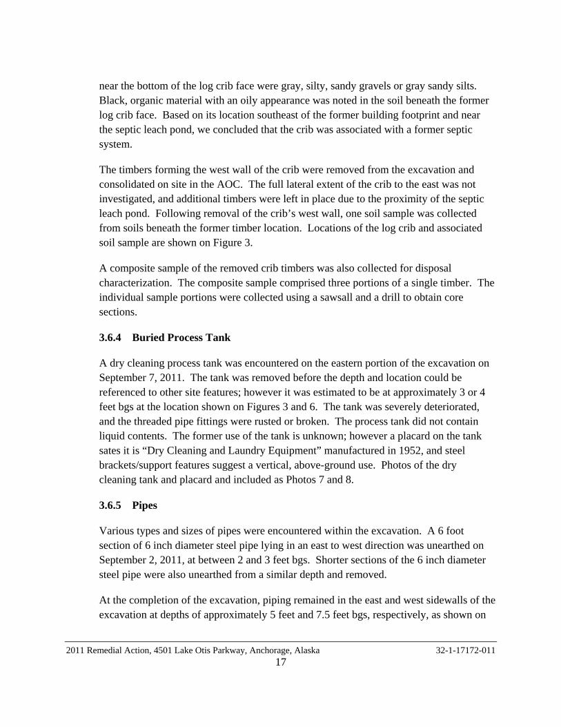
3.6.4 Buried Process Tank
A dry cleaning process tank was encountered on the eastern portion of the excavation on September 7, 2011. The tank was removed before the depth and location could be referenced to other site features; however it was estimated to be at approximately 3 or 4 feet bgs at the location shown on Figures 3 and 6. The tank was severely deteriorated, and the threaded pipe fittings were rusted or broken. The process tank did not contain liquid contents. The former use of the tank is unknown; however a placard on the tank sates it is “Dry Cleaning and Laundry Equipment” manufactured in 1952, and steel brackets/support features suggest a vertical, above-ground use. Photos of the dry cleaning tank and placard and included as Photos 7 and 8.
3.6.5 Pipes
Various types and sizes of pipes were encountered within the excavation. A 6 foot section of 6 inch diameter steel pipe lying in an east to west direction was unearthed on September 2, 2011, at between 2 and 3 feet bgs. Shorter sections of the 6 inch diameter steel pipe were also unearthed from a similar depth and removed.
At the completion of the excavation, piping remained in the east and west sidewalls of the excavation at depths of approximately 5 feet and 7.5 feet bgs, respectively, as shown on
2011 Remedial Action, 4501 Lake Otis Parkway, Anchorage, Alaska 32-1-17172-011 17
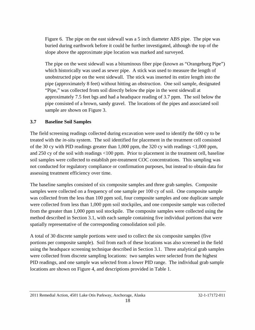
Figure 6. The pipe on the east sidewall was a 5 inch diameter ABS pipe. The pipe was buried during earthwork before it could be further investigated, although the top of the slope above the approximate pipe location was marked and surveyed.
The pipe on the west sidewall was a bituminous fiber pipe (known as “Orangeburg Pipe”) which historically was used as sewer pipe. A stick was used to measure the length of unobstructed pipe on the west sidewall. The stick was inserted its entire length into the pipe (approximately 8 feet) without hitting an obstruction. One soil sample, designated “Pipe,” was collected from soil directly below the pipe in the west sidewall at approximately 7.5 feet bgs and had a headspace reading of 3.7 ppm. The soil below the pipe consisted of a brown, sandy gravel. The locations of the pipes and associated soil sample are shown on Figure 3.
3.7 Baseline Soil Samples
The field screening readings collected during excavation were used to identify the 600 cy to be treated with the in-situ system. The soil identified for placement in the treatment cell consisted of the 30 cy with PID readings greater than 1,000 ppm, the 320 cy with readings <1,000 ppm, and 250 cy of the soil with readings <100 ppm. Prior to placement in the treatment cell, baseline soil samples were collected to establish pre-treatment COC concentrations. This sampling was not conducted for regulatory compliance or confirmation purposes, but instead to obtain data for assessing treatment efficiency over time.
The baseline samples consisted of six composite samples and three grab samples. Composite samples were collected on a frequency of one sample per 100 cy of soil. One composite sample was collected from the less than 100 ppm soil, four composite samples and one duplicate sample were collected from less than 1,000 ppm soil stockpiles, and one composite sample was collected from the greater than 1,000 ppm soil stockpile. The composite samples were collected using the method described in Section 3.1, with each sample containing five individual portions that were spatially representative of the corresponding consolidation soil pile.
A total of 30 discrete sample portions were used to collect the six composite samples (five portions per composite sample). Soil from each of these locations was also screened in the field using the headspace screening technique described in Section 3.1. Three analytical grab samples were collected from discrete sampling locations: two samples were selected from the highest PID readings, and one sample was selected from a lower PID range. The individual grab sample locations are shown on Figure 4, and descriptions provided in Table 1.
2011 Remedial Action, 4501 Lake Otis Parkway, Anchorage, Alaska 32-1-17172-011 18
3.8 Excavation Backfill and Oxidant Application
The in-situ treatment system was designed to incorporate two remediation technologies. First, VES piping will be used provide long-term capacity to conduct physical removal of volatile compounds. Second, a chemical oxidant was used to provide short-term COC concentration reduction. The oxidant slurry was applied during the excavation backfill, as described below. The combined treatment system as-built drawings are provided as Figures 5 and 6.
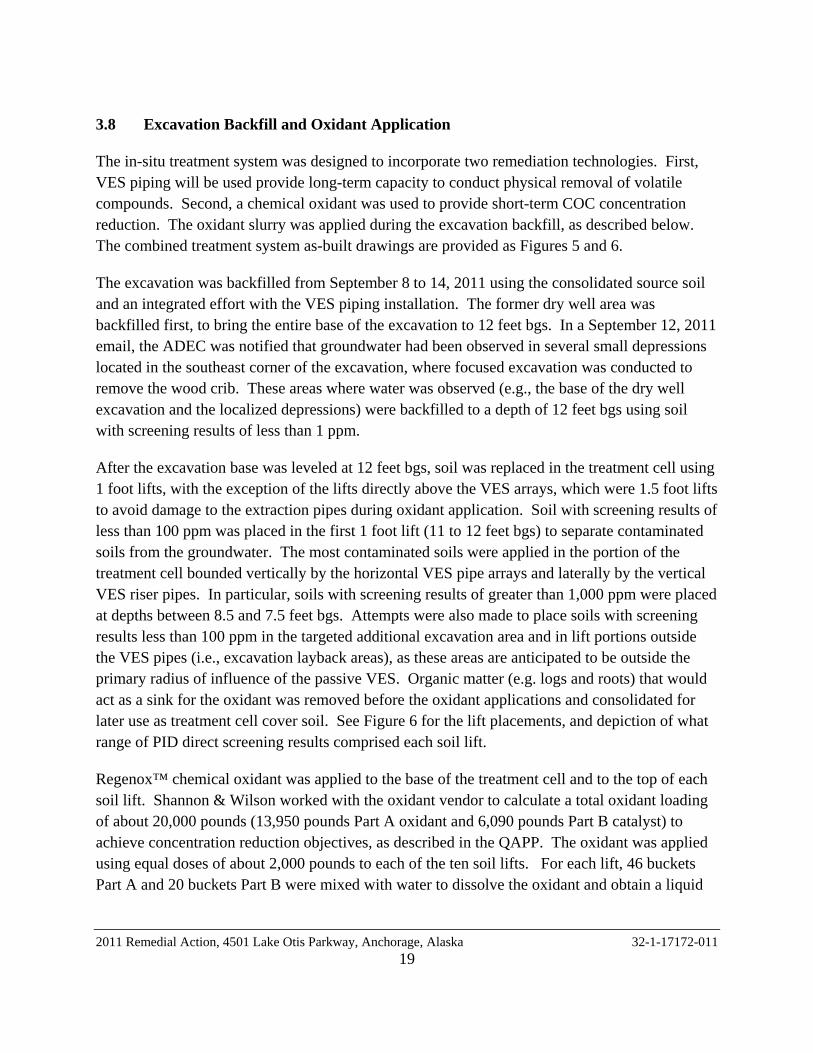
The excavation was backfilled from September 8 to 14, 2011 using the consolidated source soil and an integrated effort with the VES piping installation. The former dry well area was backfilled first, to bring the entire base of the excavation to 12 feet bgs. In a September 12, 2011 email, the ADEC was notified that groundwater had been observed in several small depressions located in the southeast corner of the excavation, where focused excavation was conducted to remove the wood crib. These areas where water was observed (e.g., the base of the dry well excavation and the localized depressions) were backfilled to a depth of 12 feet bgs using soil with screening results of less than 1 ppm.
After the excavation base was leveled at 12 feet bgs, soil was replaced in the treatment cell using 1 foot lifts, with the exception of the lifts directly above the VES arrays, which were 1.5 foot lifts to avoid damage to the extraction pipes during oxidant application. Soil with screening results of less than 100 ppm was placed in the first 1 foot lift (11 to 12 feet bgs) to separate contaminated soils from the groundwater. The most contaminated soils were applied in the portion of the treatment cell bounded vertically by the horizontal VES pipe arrays and laterally by the vertical VES riser pipes. In particular, soils with screening results of greater than 1,000 ppm were placed at depths between 8.5 and 7.5 feet bgs. Attempts were also made to place soils with screening results less than 100 ppm in the targeted additional excavation area and in lift portions outside the VES pipes (i.e., excavation layback areas), as these areas are anticipated to be outside the primary radius of influence of the passive VES. Organic matter (e.g. logs and roots) that would act as a sink for the oxidant was removed before the oxidant applications and consolidated for later use as treatment cell cover soil. See Figure 6 for the lift placements, and depiction of what range of PID direct screening results comprised each soil lift.
Regenox™ chemical oxidant was applied to the base of the treatment cell and to the top of each soil lift. Shannon & Wilson worked with the oxidant vendor to calculate a total oxidant loading of about 20,000 pounds (13,950 pounds Part A oxidant and 6,090 pounds Part B catalyst) to achieve concentration reduction objectives, as described in the QAPP. The oxidant was applied using equal doses of about 2,000 pounds to each of the ten soil lifts. For each lift, 46 buckets Part A and 20 buckets Part B were mixed with water to dissolve the oxidant and obtain a liquid
2011 Remedial Action, 4501 Lake Otis Parkway, Anchorage, Alaska 32-1-17172-011 19

solution for proper oxidant distribution. The oxidant vendor recommended solids content of 10 to 15 percent Part A solids (about 1,000 to 1,670 gallons of water per lift), but stated that the solution could be customized to fit the individual project needs and site conditions. For the first lift, BCX attempted to apply the oxidant with 750 gallons of water to limit the potential for solution ponding in the excavation, and to facilitate equipment operation within the treatment cell. The Regenox™ was mixed in a cement mixer equipped with a pump on a water truck, and a tank and spray nozzle were used to apply the oxidant solution to the excavation base. However, obtaining sufficient solute dissolution using this low water volume and cold water temperature entailed proved to be a time-consuming and labor-intensive task. For subsequent lifts, the oxidant solution was mixed and applied using hydroseeding equipment. Part A was initially added to approximately 1,000 gallons of water in the hydroseeder. The hydroseeder spray gun and pump were used to re-circulate the Part A mixture until dissolved. The Part B was added to the mixture, and then the spray gun was used to apply the Regenox™ mixture to the base of the excavation. Additional water (several hundred gallons per lift) was used to flush excess Regenox™ mixture from the hydroseeder during application. The application of the oxidant is shown on Photo 10. A roto-tiller was used to mix the oxidant into soil within each lift. The lifts were not compacted, although some compaction resulted from the excavator placing subsequent lifts.
The oxidant dosage was calculated to treat about 600 cy of impacted soil within an area generally bounded by the vertical VES riser pipes. However, due to the excavation geometry, backfill method, and low solution viscosity, confining the oxidant solution to the portion of each lift surface between the VES riser pipes proved to be impracticable, and the solution was applied over the entire lift areas (including layback areas). This resulted in an estimated soil treatment volume of 800 to 850 cy, instead of the 600 cy design volume. This variance in oxidant distribution is not expected to affect the total contaminant mass reduction potential, but may decrease the level of concentration reduction in any given unit volume. The effect may also be mitigated by the conservative assumptions used to calculate the oxidant loading rate. Specifically, elevated COC concentrations were assumed to be present throughout the treatment cell soil when in reality, the range of field screening readings suggests that the average concentration may be less.
3.9 Passive Remediation System Installation
The passive remediation system was installed on September 10 and 16, 2011. The system consists of two arrays of slotted 4-inch polyvinyl chloride (PVC) pipes installed horizontally in a north-south orientation at depths of 10 and 5.5 feet below the predominant site grade. The shallow array is off-set by 5 feet from the deeper array to enhance treatment efficiency and
2011 Remedial Action, 4501 Lake Otis Parkway, Anchorage, Alaska 32-1-17172-011 20

reduce the potential for treatment dead zones with the soil unit. As shown in Photo 11, the horizontal PVC pipes were bedded in 0.5 to 1 foot of pea gravel and wrapped in an air-permeable geotextile fabric to allow air flow, protect the pipe, and prevent silting. A specification sheet for the geotextile fabric is included as Appendix C. Vertical 4-inch PVC risers extend to approximately 4 to 5 feet above ground surface on the north and south ends of the piping array. Passive turbine vents were installed on the south vertical risers to promote air flow. The north vertical risers were capped with rubber slip caps. Details of the VES piping layouts within the in-situ treatment system are shown on Figures 5 and 6, and photographs of the pipes during and after installation are provided as Photos 12, 13, and 14.
3.10 Drinking Water Well Search
On September 15, 2011, BCX scraped approximately 1 foot of surface soil in an effort to locate the former drinking water well at the property. The drinking water well could not be located, although other buried debris, including sections of 3/4-inch steel pipe, natural gas lines, and a steel fuse valve, were found in the area.
3.11 Surveying
On September 30, 2011, Del Norte Surveying, Inc., of Anchorage Alaska conducted a professional survey of the vertical and horizontal positions of the VES risers, excavation corners, and two lathes above the approximate location of the tar pipe at the excavation’s west sidewall. Vertical elevations were determined to an accuracy of 0.01 foot, relative to the Greater Anchorage Area Borough (GAAB) 22. Horizontal positions were also determined to an accuracy of 0.01 foot (Alaska State Plane Zone 4, North American Datum of 1983). The survey report is included in Appendix D.
3.12 Site Health & Safety Measures
Site-specific health and safety measures were specified in Shannon & Wilson’s August 2011 Site Specific Health and Safety Plan (SSH&SP). At this site, particular attention was given to the potential to generate chlorinated solvent vapors when the source-area soil was disturbed. Mitigation measures included engineering controls, personal protection equipment (PPE), and ambient air monitoring.
Engineering controls included a fence to restrict site access, and installation of fans in the excavation area. As shown in Photo 9, ventilation ducts were placed inside the excavation. Shannon & Wilson’s field representative conducted ambient air monitoring during the excavation and backfill activities, in accordance with our SSH&SP. Air monitoring was
2011 Remedial Action, 4501 Lake Otis Parkway, Anchorage, Alaska 32-1-17172-011 21

conducted using a PID (for volatile organic compounds) and Q-RAE brand oxygen meter. The two meters were calibrated daily - the PID to 100 ppm isobutylene-in-air, and the Q-RAE to a zero-oxygen standard and a fresh-air calibration (with an assumed oxygen content of 20.9 percent). Due to the presence of organic vapors in the working areas, respirators were worn when soil during earthwork operations, and Saranex suits were used to protect workers from contact with potentially impacted soil.
Analytical samples of the ambient air were collected to identify specific compounds present in the working area, and to verify that the field monitoring and mitigation efforts were effective. One sample was collected in a steel summa canister, and two samples were collected using personal vapor monitoring badges.
4.0 LABORATORY ANALYSIS
The soil samples were submitted to SGS North America, Inc. (SGS) of Anchorage, Alaska using chain of custody procedures. The soil samples were analyzed for GRO by Alaska Method (AK) 101, DRO by AK 102, a short list of VOCs (PCE, TCE, cis-1,2-DCE, VC, and BTEX) by EPA Method 8260B. Instead of the short list of VOCs, the samples from the drum storage area, below the log crib, below the dry well, and one of the additional excavation sidewall samples were analyzed for full VOCs by EPA Method 8260B. Six samples were also analyzed for select PAHs by EPA Method 8270D SIMS. Samples analyzed for PAHs include the drum area sample with the greatest PID result (Sample D3S2), the two discrete baseline samples with the greatest PID results (Samples CS6S1 and CS6S5), the sidewall sample from the targeted additional excavation area with the greatest PID results (Sample SWS1), and the dry well and log crib composite samples (Samples Dry Well and LC). Grab samples from the drum area were also analyzed for RROs by AK 103.
A sample of the drum liquid contents was submitted to Emerald Alaska for hazardous characterization, and to SGS for full VOC analysis by EPA 8260B. The remaining disposal characterization samples (from the root wad, log crib, and dry well concrete) were analyzed for the short list of VOCs by EPA 8260B. The dry well concrete sample was also analyzed for DRO by AK 102.
Two air badge samples were shipped to Environmental Monitoring Technology of Hendersonville, Tennessee for VOC analysis by Method TO-15. One summa canister was submitted for BTEX and chlorinated vapor analysis to SGS. The sample was not analyzed by SGS using a validated method; therefore results are considered screening-level only.
2011 Remedial Action, 4501 Lake Otis Parkway, Anchorage, Alaska 32-1-17172-011 22
For quality control purposes, four soil trip blanks and one water trip blank were tested for GRO and either select or full VOCs. Two duplicate samples sets were analyzed for GRO, DRO, and VOCs. The duplicate Samples D3S2 and D3S4 were also analyzed for RRO.
5.0 SUBSURFACE CONDITIONS
Based on previous site assessment efforts, the site soil conditions generally consist of brown peat or brown, silty, sandy gravel from the ground surface to about 3 feet bgs. The surface soils are underlain by alternating layers of sand, silt, and gravel of varying thicknesses to the depth historically explored of 30 feet.
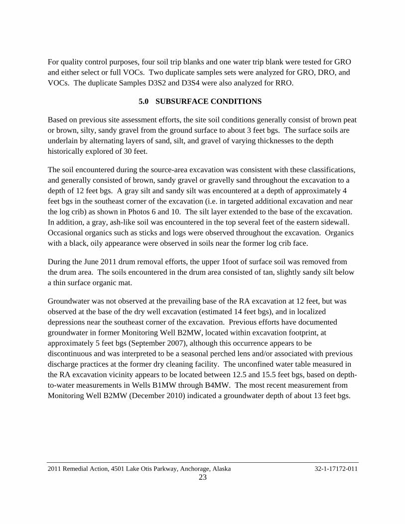
The soil encountered during the source-area excavation was consistent with these classifications, and generally consisted of brown, sandy gravel or gravelly sand throughout the excavation to a depth of 12 feet bgs. A gray silt and sandy silt was encountered at a depth of approximately 4 feet bgs in the southeast corner of the excavation (i.e. in targeted additional excavation and near the log crib) as shown in Photos 6 and 10. The silt layer extended to the base of the excavation. In addition, a gray, ash-like soil was encountered in the top several feet of the eastern sidewall. Occasional organics such as sticks and logs were observed throughout the excavation. Organics with a black, oily appearance were observed in soils near the former log crib face.
During the June 2011 drum removal efforts, the upper 1foot of surface soil was removed from the drum area. The soils encountered in the drum area consisted of tan, slightly sandy silt below a thin surface organic mat.
Groundwater was not observed at the prevailing base of the RA excavation at 12 feet, but was observed at the base of the dry well excavation (estimated 14 feet bgs), and in localized depressions near the southeast corner of the excavation. Previous efforts have documented groundwater in former Monitoring Well B2MW, located within excavation footprint, at approximately 5 feet bgs (September 2007), although this occurrence appears to be discontinuous and was interpreted to be a seasonal perched lens and/or associated with previous discharge practices at the former dry cleaning facility. The unconfined water table measured in the RA excavation vicinity appears to be located between 12.5 and 15.5 feet bgs, based on depth-to-water measurements in Wells B1MW through B4MW. The most recent measurement from Monitoring Well B2MW (December 2010) indicated a groundwater depth of about 13 feet bgs.
2011 Remedial Action, 4501 Lake Otis Parkway, Anchorage, Alaska 32-1-17172-011 23
6.0 DISCUSSION OF RESULTS
The results of the drum area, baseline, and excavation soil samples were compared to the numerical standards identified in Section 2.4. The drum area soil sample results and the drum liquid contents results are summarized in Tables 2 and 3, respectively. The excavated soil and excavation sample results are summarized in Table 4 and the waste disposal sample results are summarized in Table 5.
6.1 Drum Area Samples
DRO concentrations were reported in samples from two of the three locations, and RRO concentrations were reported samples from each location. The reported DRO and RRO concentrations are less than the most stringent ADEC Method 2 cleanup levels. The one sample tested for PAH (Sample D3S2) contained 11 individual compounds at concentrations less than 1/100th the most stringent ADEC cleanup level. GRO and VOCs were not detected in the drum area samples.
The sample of the drum’s liquid contents contained twelve VOC analytes, but did not contain detectable quantities of the halogenated solvent compounds that were identified as primary COCs for this site. Emerald Alaska noted that the drum liquid contents did not have a flashpoint, and that it was their opinion that the drum content was water.
6.2 Baseline Soil Samples
Six composite samples, one duplicate composite sample, and three grab samples were collected to document the contaminant concentrations prior to treatment. Each baseline soil sample contained a PCE concentration that exceeds the contained-in criterion. Moreover, PCE concentrations greater than the ICRT were measured in four of the six composite samples, and in each grab sample. The highest PCE concentration (707,000 µg/kg) was measured in Composite Sample CS5, which was collected from soil exhibiting PID readings <1,000 ppm. The three composite samples (two primary and one duplicate sample) with PCE concentrations less than the ICRT were collected from the soil with PID readings less than 100 ppm and less than 1,000 ppm. TCE concentrations greater than the migration to groundwater (MTG) were measured in five of the six composite samples (plus the duplicate sample), and in two of the three grab samples. The concentrations in Composite Samples CS4 and CS5 also exceed the ICRT. Concentrations of cis-1,2-DCE greater than the MTG were measured in four composite samples (plus the duplicate sample) and one grab sample. None of the cis-1,2-DCE concentrations exceed the ICRT.
2011 Remedial Action, 4501 Lake Otis Parkway, Anchorage, Alaska 32-1-17172-011 24
Concentrations of GRO and DRO greater than the MTG but less than the ICRT were reported in each composite sample except Composite Sample CS1 and CS6. Only one grab sample contained GRO or DRO greater than the MTG (260 mg/kg DRO in Sample CS7S5). BTEX analytes were detected in several samples but at concentrations less than the MTG. PAH analytes were not detected in the two samples tested for PAH, Samples CS6S1 and CS6S5.
The following inferences were drawn from the baseline sample results:
• The distribution of PCE concentrations in the RA soil samples is generally consistent with historical site characterization data. The highest concentration measured in the RA soil samples (707,000 µg/kg) is an order of magnitude less than the maximum concentration reported to date (4,520,000 µg/kg), although this difference can be at least partly attributed to the homogenization effect of the composite sampling procedure.
• The 600 cy of soil identified for placement in the in-situ treatment cell all contained concentrations greater than the ADEC MTG/ EPA contained-in standard, and thus were appropriately selected for treatment.
• Direct screening during excavation was generally an effective tool for identifying the most impacted soil, as each sample containing concentrations greater than the ICRT was collected from the soil screened as >1,000 ppm or <1,000 ppm. One of the four samples (plus one duplicate) from the <1,000 ppm soil, and the one sample from the <100 ppm soil contained concentrations less than the ICRT. Based on these data, approximately 60 percent of the soil identified for treatment (340 of 600 cy) contained concentrations greater than the ICRT.
• A qualitative evaluation of the correlation between headspace screening readings and analytical PCE concentrations was conducted, using data from the composite sample portions and grab samples. A consistent correlation was not observed, although it is noted that the two composite samples that did not contain PCE concentrations greater than the ICRT were the only two composite samples that did not comprise at least one headspace reading of 1,000 ppm or greater. Conversely, one of the three grab samples exhibited a “low-end” PID reading of 200 ppm, but contained 33,200 µg/kg PCE based on analytical results.
• The analytical results from the composite samples did not correlate well with the grab samples. Two grab samples were collected from the portions of Composite Sample CS6 that exhibited the highest PID headspace readings, and presumably should have higher concentrations than the bulk composite sample. However, the PCE concentrations in the grab samples (114,000 and 36,200 µg/kg) were substantially less than the 347,000 µg/kg PCE measured in Composite Sample CS6.
2011 Remedial Action, 4501 Lake Otis Parkway, Anchorage, Alaska 32-1-17172-011 25

• By inspection of Table 4, it is evident the incidence of elevated DRO concentrations has limited overlap with the elevated solvent concentrations. Although the sample with the highest DRO concentration (CS4) also contained elevated PCE and TCE concentrations, this correlation is not observed in Composite Sample C2/C3 (relatively high DRO concentrations) or in Samples CS6, CS7, and all three grab samples (relatively high solvent concentrations).
6.3 Excavation Samples
Each excavation sample contained a PCE concentration greater than the MTG standard, with levels ranging from 1,000 to 78,700 µg/kg PCE kg. Sample SWS1 (south-southeast excavation sidewall) and Sample LC (excavation base near the former log crib) also contained PCE concentrations greater than the ICRT. Sample SWS1 also contained a TCE concentration greater than the ICRT, and Samples SWS1 and SWS4 contained DRO and/or GRO concentrations greater than the MTG, but less than the ICRT.
Samples LC and SWS1 were also submitted for PAH and full-suite VOC analysis. Seven PAH analytes were three non-chlorinated VOC analytes (1,3,4-trimethylbenzene, 1,2,4,-trimethylbenzene, and sec-butylbenzene) were reported in the samples. The concentration of each compound is less than 1/10th the MTG standard, and all but one are less than 1/100th the MTG.
The excavation sample results are generally consistent with historical data from previous site characterization studies, but do provide more information regarding COC conditions at the edge of the in-situ treatment cell. Samples Dry Well and LC indicate that elevated PCE concentrations were present at depths (13 feet and 13.5 feet bgs, respectively) below the base of the in-situ treatment cell. Similarly, Samples SW1, SW4, and Pipe indicate PCE concentrations greater than the MTG standard are present in excavation sidewalls in the corresponding directions. Samples SW1 and SW4 further indicate DRO-impacted soil extends further southeast of the 2011 excavation boundaries.
6.4 Debris Characterization Samples
The June 30, 2011 sample of the drum’s liquid contents contains twelve petroleum hydrocarbon VOC analytes. Halogenated VOC analytes were not reported in the sample. Emerald Alaska noted that the drum liquid contents did not have a flashpoint, and that it was their opinion that the drum content was water.
2011 Remedial Action, 4501 Lake Otis Parkway, Anchorage, Alaska 32-1-17172-011 26
TCLP testing was not conducted on the disposal characterization samples, as approved by the EPA in an October 10, 2011 email. Other analytical results for the log crib material (114 mg/kg), dry well (concrete) rubble, and root wad samples are discussed in Section 7 in context of waste disposal methods.
6.5 Air Monitoring Samples
Analytical samples of ambient air included one screening-level sample to identify the specific VOC compounds present in the ambient air during earthwork, and two vapor badge samples to quantify actual worker exposure. The screening sample, which was collected from ambient air directly above freshly exposed source-area soil, contained reportable concentrations of PCE and TCE, and an estimated detection of cis-1,2-DCE. The two vapor badge samples also contained detectable PCE, but at concentrations several orders of magnitude less than the most stringent permissible exposure limit (PEL) listed in the SSHSP. VC, which was a particular concern due to its potential human health risk, was not detected in the analytical air monitoring samples. It is also noted that soil and groundwater sampling to date have not verified the presence of VC at the site.
Because the air sampling was conducted for health and safety monitoring, and not as part of the RA effort subject to contaminated sites regulation, hard copies of the lab reports are not included with this report but are available on request.
6.6 Quality Assurance Samples
The project laboratory follows on-going quality assurance/quality control (QA/QC) procedures to evaluate conformance to applicable ADEC and EPA data quality objectives (DQO). Internal laboratory quality controls for this project include surrogates, method blanks, laboratory control sample/laboratory control sample duplicates (LSC/LSCD), matrix spike/matrix spike duplicates (MS/MSD), and internal duplicates. If a DQO for one of the controls is not met, the laboratory provides a brief explanation in the case narrative of their report.
External quality controls include duplicate sample sets and trip blanks. The field duplicate samples were submitted to the laboratory to assess sample homogeneity and sampling and analytical precision. Two duplicate soil sample sets were collected. For compounds detected at concentrations greater than the limit of quantitation (LOQ) in both the project sample and duplicate, the relative percent differences (RPDs) were within the DQO and 50 percent for soil. Four soil trip blanks and one water trip blank accompanied the sample bottles from the laboratory to the site during sampling activities and back again to SGS. With the exceptions noted below, the trip blanks did not contain concentrations of volatile compounds greater than
2011 Remedial Action, 4501 Lake Otis Parkway, Anchorage, Alaska 32-1-17172-011 27
the limit of detection (LOD), indicating that the samples were not cross contaminated or exposed to contamination from the sample handling, storage process, or testing.
Shannon & Wilson reviewed the SGS data deliverables and completed an ADEC Laboratory Data Review Checklist for each work order. The laboratory reports and review checklists are included in Appendix C. No non-conformances with the DQOs were identified that would adversely affect the quality or usability of the data, except for the following:
LODs for multiple VOC analytes exceed the applicable ADEC MTG cleanup levels in the soil samples. The potential presence of these analytes at concentrations greater than the ADEC MTG cleanup levels but less than the LODs cannot be determined. The compounds that have this issue include VC, a PCE daughter product. However, the laboratory reports that is difficult to achieve a LOD less than the 8.5 µg/kg MTG cleanup level for VC. For this reason, coupled with the fact that VC has not been detected at the site, we do not consider this non-conformance to be an unresolved data gap or render the data unusable for the current project objectives.
In the drum area sample work order, anthracene was detected in the method blank at a concentration several times greater than in the project sample. This result is flagged as an estimate.
Methylene chloride was detected in the water trip blank, and carbon disulfide was detected in the trip blank associated with the drum area soil samples. Methylene chloride is a common lab contaminant; therefore, we believe the detection is an effect of the lab processes. The source of the carbon disulfide is unknown. Because the associated project samples do not contain detectable concentrations of these analytes, the detections do not adversely affect the usability of the data.
DRO concentrations are biased high for the concrete disposal sample (Sample Concrete-S1) due to contributions from heavier hydrocarbons. The VOC analysis is primarily used for disposal characterization, and is not affected. Therefore, the data are still usable for the purpose of this project.
2011 Remedial Action, 4501 Lake Otis Parkway, Anchorage, Alaska 32-1-17172-011 28
7.0 INVESTIGATION DERIVED WASTE
The following summary lists each solid waste generated, along with the corresponding volume, regulatory status, and proposed or completed disposal method.
Buried Drums. Two of the three drums located during the drum removal effort were empty. These drums were brushed to remove soil, and disposed by BCX as scrap metal. The third drum, which contained approximately 10 gallons of liquid, was placed in an overpack drum and removed by Emerald Alaska on August 12, 2011.
Land Clearing Debris. This consists of the cleared grass, brush, and other surface vegetation that is materially free of soil. The material is presently consolidated on three wood pallets within the AOC, and will be transported off site for disposal as unregulated waste at an inert waste monofill. The EPA has approved the disposal method, and disposal is slated for spring 2012.
Organic Soil. This material comprises organic soil that was disturbed as part of the pre-excavation site preparation activities, and grubbed material that contains sufficient soil volume such that it cannot be disposed as land-clearing debris. This soil was applied to the top of the treatment cell on September 16, 2011, following EPA approval (9/21/11 email).
Debris – Root Mass. Several larger trees were cut to enable equipment access. The above-ground portions will be addressed as land-clearing debris as specified above. The below-ground portions were tested and found to contain COC concentrations less than the TCLP, UTS, and site-specific debris contained-in concentrations. Because the sample contained less than 0.5 mg/kg PCE, the proposed disposal method for the three supersacks of root mass is the MOA municipal landfill. EPA indicated general approval of this method, subject to the Regional Administrator’s approval of the proposed contained-in levels. Once EPA approval is granted, written approval will also be obtained from MOA prior to transport.
Debris – Concrete Rubble. The concrete debris from the former dry well was consolidated into one supersack, which remains stored on a pallet within the AOC. The composite sample from this material contained COC concentrations less than the TCLP, UTS, and site-specific debris contained-in concentrations. However, because the PCE concentration is greater than 0.5 mg/kg, the MOA municipal landfill cannot receive this waste, and it will therefore be transported and disposed at a RCRA Subtitle C landfill as a RCRA-regulated waste. Transport and disposal is slated for spring 2012.
2011 Remedial Action, 4501 Lake Otis Parkway, Anchorage, Alaska 32-1-17172-011 29

Debris – Crib Material. The wood timbers from the former buried crib were consolidated into one supersack, which remains stored on a pallet within the AOC. The composite sample from this material contained COC concentrations greater than the UTS and site-specific debris contained-in standards, and presumably also the TCLP standard. This supersack will be transported and disposed at a RCRA Subtitle C landfill as a RCRA-regulated waste. Transport and disposal is slated for spring 2012.
Debris - Process Tank and Piping. These materials comprise the process tank and miscellaneous piping encountered during the excavation activities. The proposed disposal method is to conduct a dry decontamination to remove soil, then recycle the materials as scrap metal. Presently, the materials are consolidated on two pallets within the AOC. EPA has not yet responded to requests to approve this plan, and it is hoped that such approval will be granted in January 2012 concurrent with the Regional Administrator review of the proposed contained-in levels.
Other Non-Regulated Solid Waste. Miscellaneous construction materials (i.e. liners, buckets) were cleaned of excess dirt disposed of as solid waste at the Anchorage municipal landfill.
8.0 CONCEPTUAL SITE MODEL
A Conceptual Site Model (CSM) was prepared to identify known and potential exposure pathways associated with contaminants of concern at the subject site. The CSM was developed in general accordance with the ADEC’s Policy Guidance on Developing Conceptual Site Models (October 2010), using ADEC’s CSM Human Health Graphic and Scoping Forms. Copies of the Human Health Graphic and Scoping Forms are included as Appendix E.
The CSM includes a discussion of exposure routes, potential receptors, and complete potentially or complete exposure pathways. The CSM is based on the current use of the Property as an unoccupied lot with no building structures. The known petroleum hydrocarbon and VOC contaminant groundwater plume does not appear to extend off the Property to the south onto adjacent residential and commercial properties. The groundwater plume may extend off site to the north, although the relative contributions of the Peacock Cleaner plume and the contaminated site to the north (former Chevron filling station) are not fully understood. A re-examination of potential exposure pathways may be needed if land use, access, or other site conditions change.
As discussed in Section 2.4, the COCs for this site comprise GRO, DRO, benzene, PCE, TCE and cis-1,2-DCE in both soil and groundwater. RRO is also a COC in groundwater. VC and PAHs are retained as COPCs. VC has not been detected in the site’s soil or groundwater, but is a degradation product of the reductive dechlorination process for PCE, TCE, and DCE, and may be produced as these compounds degrade. Individual PAH have been detected site soil samples
2011 Remedial Action, 4501 Lake Otis Parkway, Anchorage, Alaska 32-1-17172-011 30
at concentrations two to six orders of magnitude less than the most stringent ADEC Method 2 cleanup levels. Because these concentrations are below 1/10th the ADEC cleanup levels, typically the corresponding exposure pathways can be considered insignificant per ADEC guidance.
8.1 Soil Direct Contact
Direct contact with impacted soil comprises the incidental ingestion, dermal contact, and fugitive dust exposure routes. The direct contact exposure pathway is complete for current trespassers and construction workers and future on-site commercial workers, site visitors, trespassers and/or construction workers. Exposure for receptors is presently mitigated by access controls (fence). This exposure pathway will require further mitigation through treatment, capping, and/or institutional controls prior to Property reuse / redevelopment. Note the in-situ treatment system installed during this RA was designed to reduce source-area COC concentrations in soil to levels below the ADEC’s Method 2 cleanup levels for the direct contact exposure routes.
8.2 Groundwater Ingestion
COCs have been measured in the site’s groundwater at concentrations greater than the ADEC Table C standards. There are presently no known human receptors, as the on-site well is not in use, and could not be located during the 2011 field activities. However, ADEC guidance stipulates that ingestion of groundwater be considered a potentially complete exposure pathway unless a groundwater use determination is conducted in accordance with 18 AAC 75.350, and that determination finds that the groundwater is not “a currently or reasonably expected future source of drinking water.” Therefore, ingestion of impacted groundwater is a potentially complete exposure pathway for future human receptors, if the groundwater on site or the immediate vicinity is used as a drinking water source.
As stated above, a drinking water well was formerly located on the property, near the northeast corner of the former Peacock Cleaners structure. It appears the drinking water well has been removed from the Property, although this has not been verified through documentation or field observations. The potential presence of additional drinking water wells in the project vicinity was assessed by E&E in fall 2009. Four wells reportedly used for drinking water were identified within a 1-mile radius. The nearest water well is located 0.4 mile to the northeast, which is topographically upgradient from the site. The nearest topographically downgradient/ crossgradient water well is 0.9 mile to the southwest. Regional groundwater flow is generally expected to be governed by the topographical gradient towards Campbell Creek to the south/southeast , although localized variability has also been observed.
2011 Remedial Action, 4501 Lake Otis Parkway, Anchorage, Alaska 32-1-17172-011 31
8.3 Outdoor Air Inhalation
Volatile COCs, chlorinated solvents in particular, have the potential to impact receptors through outdoor air inhalation. The presence of VOC concentrations in soil within the top 15 feet bgs creates a potentially complete exposure pathway for current and/or future site users and residents of nearby properties. This exposure pathway will require further mitigation through treatment, capping, and/or institutional controls prior to site reuse / redevelopment. Note the in-situ treatment system installed during this RA was designed to reduce source-area COC concentrations in soil to levels below the ADEC’s Method 2 cleanup levels for the outdoor inhalation exposure route.
8.4 Indoor Air Inhalation / Vapor Intrusion
Vapor intrusion (VI) is a concern for occupied buildings within 100 feet of impacted soil or groundwater. There are presently no structures on the Property. The nearest off-Property occupied structures (apartment buildings to the east and south) may be within 100 feet from the impacted media. Although risk-based soil cleanup standards have not been promulgated for VI assessment, ADEC has stated this exposure pathway will need to be further assessed for both existing off-Property structures and prior to implementing on-Property reuse/redevelopment scenario(s) that entail construction of enclosed structures. A work plan to investigate the VI exposure pathway has been approved by ADEC, and field work is presently scheduled for January 2012.
8.5 Surface Water
The proximity of the subject site to Campbell Creek indicates a regional hydraulic connection between groundwater and surface water. Migration to surface water is not considered a presently complete exposure pathway for the subject site, as there is no evidence that the impacted groundwater plume extends to Campbell Creek, and the creek is not used as a human drinking water source. This exposure pathway is retained for future consideration, in the event the impacted groundwater plume is not stable, and potential human or ecological receptors are identified.
8.6 Other
Other impacted media, including sediment and biota, were not identified at the subject property.
2011 Remedial Action, 4501 Lake Otis Parkway, Anchorage, Alaska 32-1-17172-011 32
8.7 CSM Summary
Complete or potentially complete exposure pathways have been identified at the Property. Direct exposure to impacted soil and groundwater is presently controlled by the fence surrounding the Property and the absence of on-site water wells. Additional treatment or other mitigation will be required prior to site reuse / redevelopment, both to further address these pathways, and to reduce potential exposure through indoor and outdoor vapor inhalation. Towards this end, the in-situ treatment system installed during the RA was designed to reduce source-area COC concentrations in soil to levels below the ADEC’s Method 2 cleanup levels for the direct contact and outdoor air inhalation exposure routes. The system’s effectiveness in reducing source-area concentrations to levels less than target risk-based thresholds will be assessed using the progress sampling event slated for spring 2012.
It is also recognized that changes in the site use or other site conditions may affect the viability of potential exposure pathways. In particular, the CSM will need to be re-evaluated and revised as necessary if the fence is removed, new buildings are constructed at the site, a change in land use occurs, and/or the impacted groundwater plume expands.
9.0 SUMMARY
Activities conducted during this RA effort include removing and disposing three buried drums, excavating impacted soil for on-site consolidation, baseline soil sampling, and installing an in-situ vapor extraction and chemical oxidant treatment system.
A drum investigation in June 2011 revealed three partially-buried drums. One drum contained liquid contents, which were tested for hazardous content, and then disposed off-site by Emerald. The other two drums were removed and disposed as scrap metal. Soil samples collected beneath the drums contained DRO and RRO concentrations less than the most stringent applicable cleanup levels, and did not contain detectable concentrations of the chlorinated solvent COCs.
An estimated 1,190 cy of soil was removed from the source-area excavation and segregated using direct-measurement field screening. Field screening results were used to select 600 cy soil for in-situ treatment. Baseline sample results from these soils indicated that all 600 cy contained PCE concentrations greater than the MTG cleanup level, and an estimated 60 percent also contained PCE concentrations greater than the ICRT. The results of limited excavation sampling indicate that contaminant concentrations greater than the MTG standard remain at the base and sidewalls of the treatment cell, and PCE concentration greater than the ICRT remain at the southwest sidewall of the additional excavation area and below the former log crib.
2011 Remedial Action, 4501 Lake Otis Parkway, Anchorage, Alaska 32-1-17172-011 33
The in-situ treatment system was installed using a total of ten horizontal soil VES pipes. The pipes were installed in two arrays of five pipes each at depths of about 5.5 and 10 feet below the prevailing grade. The VES was installed to operate in a passive mode, but can be converted to an active system if more aggressive treatment within the treatment cell is desired.
During VES piping installation and backfill, a total of about 20,000 pounds of chemical oxidant were tilled into the treatment system soil. Due to excavation geometry and the liquid nature of the oxidant solution, the volume of soil exposed to the oxidant solution is estimated at about 800 to 850 cy, instead of the targeted 600 cy. However, the total mass reduction potential of the oxidant solution should not be diminished, and the layered method of backfilling and applying oxidant solution should reduce the potential adverse effect on the immediate treatment objective.
During the September 2011 excavation, buried debris were unexpectedly encountered in the treatment system footprint. Removed debris includes a portion of a log crib, a concrete dry well, pipe, and a process tank. These materials, along with tree roots removed from the south side of the treatment cell soil, were consolidated within the AOC pending disposal. A plan for disposal has been submitted to the EPA and will be implemented in spring 2012 if approved by EPA and ADEC.
An assessment of the effectiveness of the remediation was not conducted under this scope of work, although it is preliminarily scheduled for spring 2012. At that time, soil samples will be collected from the treatment cell to document the remaining contaminant concentration, and a new monitoring well northwest of the treatment cell will be installed.
The concrete casing around Monitoring Well MW16 appeared to be damaged. We recommend investigating this condition of this well, and repairing or decommissioning this well, as appropriate, during the spring confirmation sampling.
10.0 CLOSURE/LIMITATIONS
This report was prepared for the exclusive use of our client and their representatives in the study of this site. The findings we have presented within this report are based on the limited research, sampling, and analyses that we conducted at this site. They should not be construed as definite conclusions regarding the site’s soil quality. As a result, the analysis and sampling performed can only provide you with our professional judgment as to the environmental characteristics of this site, and in no way guarantees that an agency or its staff will reach the same conclusions as Shannon & Wilson, Inc. The data presented in this report should be considered representative of the time of our site assessment. Changes in site conditions can occur over time, due to natural forces or human activity. In addition, changes in government codes, regulations, or laws may
2011 Remedial Action, 4501 Lake Otis Parkway, Anchorage, Alaska 32-1-17172-011 34

TABLE 1SAMPLE LOCATIONS AND DESCRIPTIONS
SHANNON & WILSON, INC.
Sample Location Depth HeadspaceDate (See Figures 2 through 4) (feet) (ppm) ^ Sample Classification
Drum Area Samples
D1S1 6/9/2011 Partially buried drum area, below Drum 1 1 14 Tan, slightly sandy SILT; moist; scattered organicsD1S2 6/9/2011 Partially buried drum area, below Drum 1 1 19 Tan, slightly sandy SILT; moist; scattered organics
* D1S3 6/9/2011 Partially buried drum area, below Drum 1 1.5 19 Tan, slightly sandy SILT; moist; scattered organics* D2S1 6/9/2011 Partially buried drum area, below Drum 2 1 5.9 Tan, slightly sandy SILT; moist; scattered organics
D2S2 6/9/2011 Partially buried drum area, below Drum 2 1 3.7 Tan, slightly sandy SILT; moist; scattered organicsD2S3 6/9/2011 Partially buried drum area, below Drum 2 1 3.7 Tan, slightly sandy SILT; moist; scattered organicsD3S1 6/9/2011 Partially buried drum area, below Drum 3 1 3.0 Tan, slightly gravelly, sandy SILT; moist; scattered organics
* D3S2 6/9/2011 Partially buried drum area, below Drum 3 1 92 Tan, slightly gravelly, sandy SILT; moist; scattered organics* D3S4 6/9/2011 Duplicate of D3S2 1 92 Tan, slightly gravelly, sandy SILT; moist; scattered organics
D3S3 6/9/2011 Partially buried drum area, below Drum 3 1 12 Tan, slightly gravelly, sandy SILT; moist; scattered organics
Baseline Soil Samples
* CS1 9/7/2011 Composite Sample CS1 comprising portions of Samples CS1S1 through CS1S5 from the Northeast Consolidation Area
1.5 - Five discrete soil samples comprising one composite sample
CS1S1 9/7/2011 Soil with <100 ppm^ in Northeast Consolidation Area 1.5 26 Brown, silty, sandy GRAVEL; moistCS1S2 9/7/2011 Soil with <100 ppm^ in Northeast Consolidation Area 1.5 28 Brown, silty, sandy GRAVEL; moistCS1S3 9/7/2011 Soil with <100 ppm in Northeast Consolidation Area 1.5 27 Brown, silty, sandy GRAVEL; moistCS1S4 9/7/2011 Soil with <100 ppm^ in Northeast Consolidation Area 1.5 38 Brown, silty, sandy GRAVEL; moistCS1S5 9/7/2011 Soil with <100 ppm^ in Northeast Consolidation Area 1.5 22 Brown, silty, sandy GRAVEL; moist
* CS2 9/7/2011 Composite Sample CS2 comprising portions of Samples CS2S1 through CS2S5 from the Northeast Consolidation Area
1.5 - Five discrete soil samples comprising one composite sample
* CS3 9/7/2011 Duplicate of CS2 1.5 - Five discrete soil samples comprising one composite sampleCS2S1 9/7/2011 Soil with <1,000 ppm^ in Northeast Consolidation Area 1.5 820 Brown, slightly sandy, slightly gravelly SILT; moist; scattered organicsCS2S2 9/7/2011 Soil with <1,000 ppm^ in Northeast Consolidation Area 1.5 900 Gray, slightly sandy SILT; moistCS2S3 9/7/2011 Soil with <1,000 ppm^ in Northeast Consolidation Area 1.5 760 Gray, silty, sandy GRAVEL; moistCS2S4 9/7/2011 Soil with <1,000 ppm^ in Northeast Consolidation Area 1.5 840 Brown, slightly sandy, gravelly SILT; moistCS2S5 9/7/2011 Soil with <1,000 ppm^ in Northeast Consolidation Area 1.5 370 Brown, slightly sandy, gravelly SILT; moist
NOTES:* =Sample analyzed by the project laboratory (See Tables 2 through 5)^ =Field screening instrument was a ThermoInstruments 580B photoionization detector (PID)- =Measurement not recorded or not applicable
ppm =parts per million
Sample Number
December 2011 32-1-17172-011, 4501 Lake Otis Parkway, Anchorage, Alaska Table 1 / Page 1 of 3
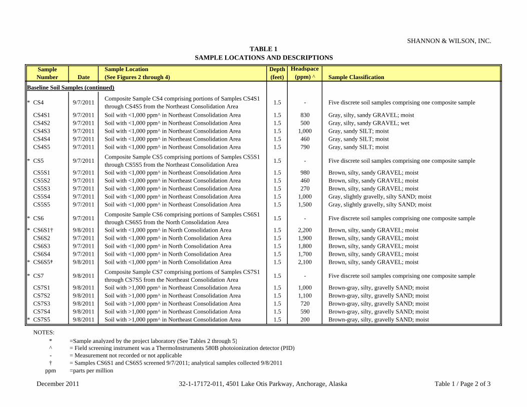
TABLE 1SAMPLE LOCATIONS AND DESCRIPTIONS
SHANNON & WILSON, INC.
Sample Location Depth HeadspaceDate (See Figures 2 through 4) (feet) (ppm) ^ Sample Classification
Sample Number
Baseline Soil Samples (continued)
* CS4 9/7/2011 Composite Sample CS4 comprising portions of Samples CS4S1 through CS4S5 from the Northeast Consolidation Area
1.5 - Five discrete soil samples comprising one composite sample
CS4S1 9/7/2011 Soil with <1,000 ppm^ in Northeast Consolidation Area 1.5 830 Gray, silty, sandy GRAVEL; moistCS4S2 9/7/2011 Soil with <1,000 ppm^ in Northeast Consolidation Area 1.5 500 Gray, silty, sandy GRAVEL; wetCS4S3 9/7/2011 Soil with <1,000 ppm^ in Northeast Consolidation Area 1.5 1,000 Gray, sandy SILT; moistCS4S4 9/7/2011 Soil with <1,000 ppm^ in Northeast Consolidation Area 1.5 460 Gray, sandy SILT; moistCS4S5 9/7/2011 Soil with <1,000 ppm^ in Northeast Consolidation Area 1.5 790 Gray, sandy SILT; moist
* CS5 9/7/2011 Composite Sample CS5 comprising portions of Samples CS5S1 through CS5S5 from the Northeast Consolidation Area
1.5 - Five discrete soil samples comprising one composite sample
CS5S1 9/7/2011 Soil with <1,000 ppm^ in Northeast Consolidation Area 1.5 980 Brown, silty, sandy GRAVEL; moistCS5S2 9/7/2011 Soil with <1,000 ppm^ in Northeast Consolidation Area 1.5 460 Brown, silty, sandy GRAVEL; moistCS5S3 9/7/2011 Soil with <1,000 ppm^ in Northeast Consolidation Area 1.5 270 Brown, silty, sandy GRAVEL; moistCS5S4 9/7/2011 Soil with <1,000 ppm^ in Northeast Consolidation Area 1.5 1,000 Gray, slightly gravelly, silty SAND; moistCS5S5 9/7/2011 Soil with <1,000 ppm^ in Northeast Consolidation Area 1.5 1,500 Gray, slightly gravelly, silty SAND; moist
* CS6 9/7/2011 Composite Sample CS6 comprising portions of Samples CS6S1 through CS6S5 from the North Consolidation Area
1.5 - Five discrete soil samples comprising one composite sample
* CS6S1† 9/8/2011 Soil with <1,000 ppm^ in North Consolidation Area 1.5 2,200 Brown, silty, sandy GRAVEL; moistCS6S2 9/7/2011 Soil with <1,000 ppm^ in North Consolidation Area 1.5 1,900 Brown, silty, sandy GRAVEL; moistCS6S3 9/7/2011 Soil with <1,000 ppm^ in North Consolidation Area 1.5 1,800 Brown, silty, sandy GRAVEL; moistCS6S4 9/7/2011 Soil with <1,000 ppm^ in North Consolidation Area 1.5 1,700 Brown, silty, sandy GRAVEL; moist
* CS6S5† 9/8/2011 Soil with <1,000 ppm^ in North Consolidation Area 1.5 2,100 Brown, silty, sandy GRAVEL; moist
* CS7 9/8/2011 Composite Sample CS7 comprising portions of Samples CS7S1 through CS7S5 from the Northeast Consolidation Area
1.5 - Five discrete soil samples comprising one composite sample
CS7S1 9/8/2011 Soil with >1,000 ppm^ in Northeast Consolidation Area 1.5 1,000 Brown-gray, silty, gravelly SAND; moistCS7S2 9/8/2011 Soil with >1,000 ppm^ in Northeast Consolidation Area 1.5 1,100 Brown-gray, silty, gravelly SAND; moistCS7S3 9/8/2011 Soil with >1,000 ppm^ in Northeast Consolidation Area 1.5 720 Brown-gray, silty, gravelly SAND; moistCS7S4 9/8/2011 Soil with >1,000 ppm^ in Northeast Consolidation Area 1.5 590 Brown-gray, silty, gravelly SAND; moist
* CS7S5 9/8/2011 Soil with >1,000 ppm^ in Northeast Consolidation Area 1.5 200 Brown-gray, silty, gravelly SAND; moist
NOTES:* =Sample analyzed by the project laboratory (See Tables 2 through 5)^ = Field screening instrument was a ThermoInstruments 580B photoionization detector (PID)- = Measurement not recorded or not applicable† = Samples CS6S1 and CS6S5 screened 9/7/2011; analytical samples collected 9/8/2011
ppm =parts per million
December 2011 32-1-17172-011, 4501 Lake Otis Parkway, Anchorage, Alaska Table 1 / Page 2 of 3
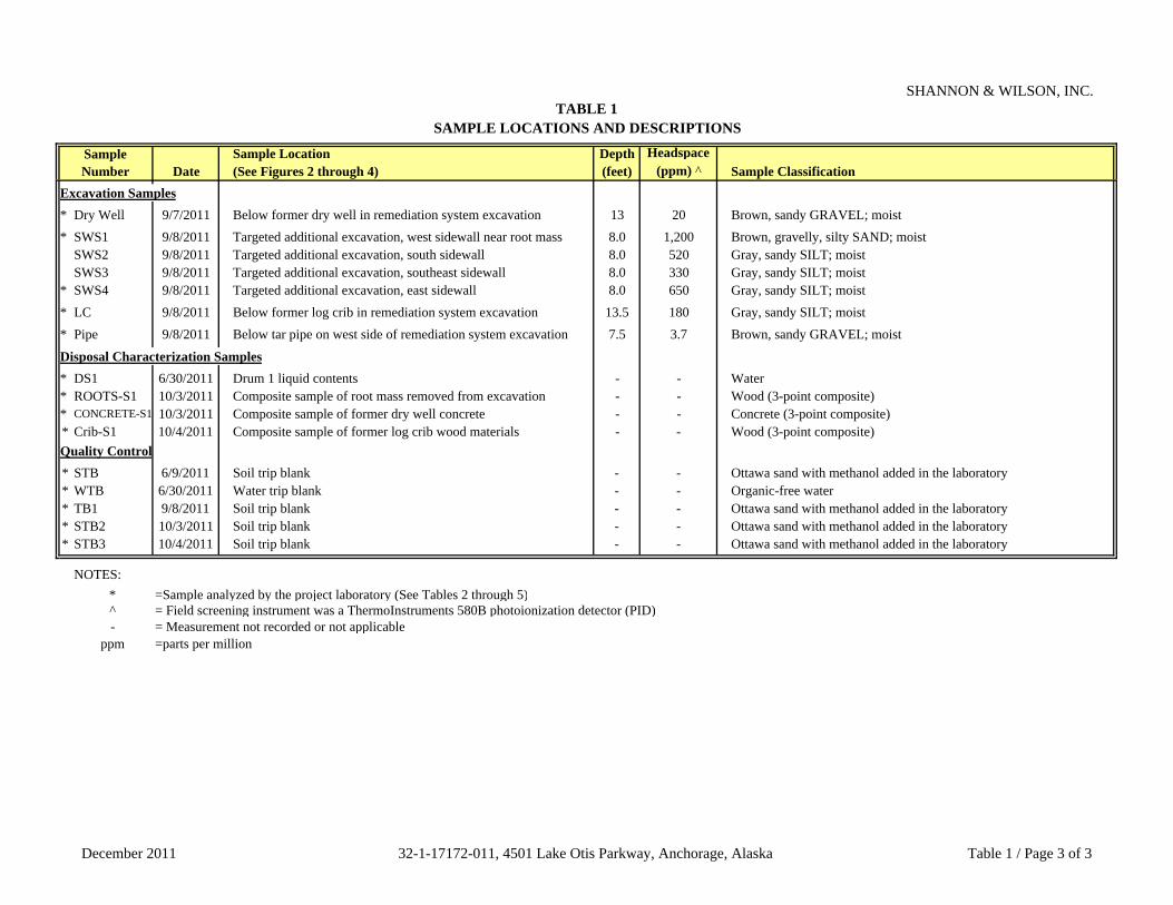
TABLE 1SAMPLE LOCATIONS AND DESCRIPTIONS
SHANNON & WILSON, INC.
Sample Location Depth HeadspaceDate (See Figures 2 through 4) (feet) (ppm) ^ Sample Classification
Sample Number
Excavation Samples* Dry Well 9/7/2011 Below former dry well in remediation system excavation 13 20 Brown, sandy GRAVEL; moist* SWS1 9/8/2011 Targeted additional excavation, west sidewall near root mass 8.0 1,200 Brown, gravelly, silty SAND; moist
SWS2 9/8/2011 Targeted additional excavation, south sidewall 8.0 520 Gray, sandy SILT; moistSWS3 9/8/2011 Targeted additional excavation, southeast sidewall 8.0 330 Gray, sandy SILT; moist
* SWS4 9/8/2011 Targeted additional excavation, east sidewall 8.0 650 Gray, sandy SILT; moist* LC 9/8/2011 Below former log crib in remediation system excavation 13.5 180 Gray, sandy SILT; moist* Pipe 9/8/2011 Below tar pipe on west side of remediation system excavation 7.5 3.7 Brown, sandy GRAVEL; moist
Disposal Characterization Samples* DS1 6/30/2011 Drum 1 liquid contents - - Water* ROOTS-S1 10/3/2011 Composite sample of root mass removed from excavation - - Wood (3-point composite)* CONCRETE-S1 10/3/2011 Composite sample of former dry well concrete - - Concrete (3-point composite)* Crib-S1 10/4/2011 Composite sample of former log crib wood materials - - Wood (3-point composite)Quality Control* STB 6/9/2011 Soil trip blank - - Ottawa sand with methanol added in the laboratory* WTB 6/30/2011 Water trip blank - - Organic-free water* TB1 9/8/2011 Soil trip blank - - Ottawa sand with methanol added in the laboratory* STB2 10/3/2011 Soil trip blank - - Ottawa sand with methanol added in the laboratory* STB3 10/4/2011 Soil trip blank - - Ottawa sand with methanol added in the laboratory
NOTES:* =Sample analyzed by the project laboratory (See Tables 2 through 5)^ = Field screening instrument was a ThermoInstruments 580B photoionization detector (PID)- = Measurement not recorded or not applicable
ppm =parts per million
December 2011 32-1-17172-011, 4501 Lake Otis Parkway, Anchorage, Alaska Table 1 / Page 3 of 3

TABLE 2 SUMMARY OF DRUM AREA SOIL SAMPLE ANALYTICAL RESULTS
SHANNON & WILSON, INC.
QCD1S3 D2S1 D3S2 D3S4~ STB1.5 1 1 1 -
PID Headspace Reading - ppm 580B PID - 19 5.9 92 92 -
Total Solids - percent SM20-2540G - 87.4 91.9 95.0 94.2 -
Gasoline Range Organics (GRO) - mg/kg AK 101 300 <2.54 <1.91 <1.75 <1.83 <1.51
Diesel Range Organics (DRO) - mg/kg AK 102 250 68.8 <13.5 19.7 J 23.8 -
Residual Range Organics (DRO) - mg/kg AK 103 10,000 211 42.8 101 136 -
Volatile Organic Compounds (VOC)Benzene - µg/kg EPA 8260B 25 <13.2 <9.94 <9.08 <9.52 <7.86Toluene - µg/kg EPA 8260B 6,500 <51.0 <38.2 <35.0 <36.6 <30.2Ethylbenzene - µg/kg EPA 8260B 6,900 <26.4 <19.9 <18.2 <19.1 <15.7Xylenes (total) - µg/kg EPA 8260B 63,000 <105 <79.0 <72.2 <75.8 <62.4Tetrachloroethene - µg/kg EPA 8260B 24 <13.2 <9.94 <9.08 <9.52 <7.86Trichloroethene - µg/kg EPA 8260B 20 <13.2 <9.94 <9.08 <9.52 <7.86cis -1,2-Dichloroethene - µg/kg EPA 8260B 30 <26.4 <19.9 <18.2 <19.1 <15.7Vinyl Chloride - µg/kg EPA 8260B 8.5 <26.4 <19.9 <18.2 <19.1 <15.7Carbon Disulfide - µg/kg EPA 8260B 12,000 <105 <79.0 <72.2 <75.8 50.6 JOther VOC analytes EPA 8260B Varies ND ND ND ND ND
Polyaromatic Hydrocarbons (PAHs)Anthracene - µg/kg EPA 8270D SIMS 3,000,000 - - <1.60 B - -Benzo(a)Anthracene - µg/kg EPA 8270D SIMS 3,600 - - 10.8 - -Benzo[a]pyrene - µg/kg EPA 8270D SIMS 2,100 - - 12.3 - -Benzo[b]Fluoranthene - µg/kg EPA 8270D SIMS 12,000 - - 12.0 - -Benzo[g,h,i]perylene - µg/kg EPA 8270D SIMS 38,700,000 - - 8.03 - -Benzo[k]flouranthene - µg/kg EPA 8270D SIMS 120,000 - - 2.55 J - -Chrysene- µg/kg EPA 8270D SIMS 360,000 - - 14.7 - -Dibenzo[a,h]anthracene - µg/kg EPA 8270D SIMS 4,000 - - 1.84 J - -Fluoranthene - µg/kg EPA 8270D SIMS 1,400,000 - - 8.43 - -Indeno[1,2,3-c,d]pyrene - µg/kg EPA 8270D SIMS 41,000 - - 4.36 J - -Phenanthrene - µg/kg EPA 8270D SIMS 3,000,000 - - 5.38 - -Pyrene - µg/kg EPA 8270D SIMS 1,000,000 - - 9.09 - -Other PAH analytes EPA 8270D SIMS Varies - - ND - -
* See Appendix B for compounds tested, methods, and laboratory reporting limits** Cleanup levels are most stringent Method 2 listed in Table B1 or B2, 18 AAC 75, for "under 40 inches (precipitation) zone" [Oct. 1, 2011].
^ = Sample ID No. preceded by "17172-6-" on the chain of custody form~ = Duplicate of preceding sample
<13.2 = Analyte not detected above the limit of detection (LOD) of 13.2 units (µg/kg or mg/kg, as applicable)<26.4 = Laboratory LOD is greater than the ADEC cleanup level
- = Not applicable or sample not tested for this analyteµg/kg = Micrograms per kiligrammg/kg = Milligrams per kilogramppm = Parts per millionND =Not detectedQC =Quality controlB =Results are estimated due to the detection in the method blank greater than in the project sampleJ =Results are an estimate less than the limit of quantitation
Parameter Tested
Sample ID^ and Collection Depth in Feet
Cleanup Level**Method*
Drum Area Samples
December 2011 32-1-17172-011, 4501 Lake Otis Parkway, Anchorage, Alaska Table 2 / Page 1 of 1
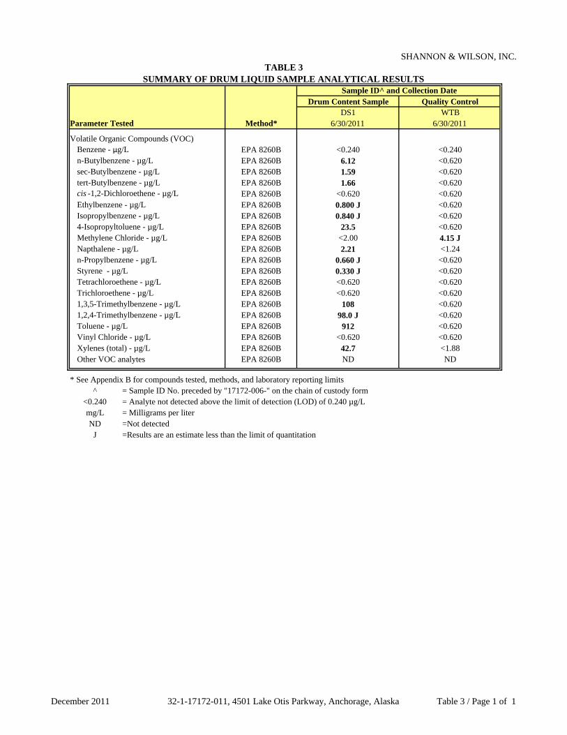
TABLE 3 SUMMARY OF DRUM LIQUID SAMPLE ANALYTICAL RESULTS
SHANNON & WILSON, INC.
Drum Content Sample Quality ControlDS1 WTB
6/30/2011 6/30/2011
Volatile Organic Compounds (VOC)Benzene - µg/L EPA 8260B <0.240 <0.240n-Butylbenzene - µg/L EPA 8260B 6.12 <0.620sec-Butylbenzene - µg/L EPA 8260B 1.59 <0.620tert-Butylbenzene - µg/L EPA 8260B 1.66 <0.620cis -1,2-Dichloroethene - µg/L EPA 8260B <0.620 <0.620Ethylbenzene - µg/L EPA 8260B 0.800 J <0.620Isopropylbenzene - µg/L EPA 8260B 0.840 J <0.6204-Isopropyltoluene - µg/L EPA 8260B 23.5 <0.620Methylene Chloride - µg/L EPA 8260B <2.00 4.15 JNapthalene - µg/L EPA 8260B 2.21 <1.24n-Propylbenzene - µg/L EPA 8260B 0.660 J <0.620Styrene - µg/L EPA 8260B 0.330 J <0.620Tetrachloroethene - µg/L EPA 8260B <0.620 <0.620Trichloroethene - µg/L EPA 8260B <0.620 <0.6201,3,5-Trimethylbenzene - µg/L EPA 8260B 108 <0.6201,2,4-Trimethylbenzene - µg/L EPA 8260B 98.0 J <0.620Toluene - µg/L EPA 8260B 912 <0.620Vinyl Chloride - µg/L EPA 8260B <0.620 <0.620Xylenes (total) - µg/L EPA 8260B 42.7 <1.88Other VOC analytes EPA 8260B ND ND
* See Appendix B for compounds tested, methods, and laboratory reporting limits^ = Sample ID No. preceded by "17172-006-" on the chain of custody form
<0.240 = Analyte not detected above the limit of detection (LOD) of 0.240 µg/Lmg/L = Milligrams per literND =Not detected
J =Results are an estimate less than the limit of quantitation
Sample ID^ and Collection Date
Parameter Tested Method*
December 2011 32-1-17172-011, 4501 Lake Otis Parkway, Anchorage, Alaska Table 3 / Page 1 of 1

TABLE 4 SUMMARY OF CONSOLIDATATION AREA AND EXCAVATION SOIL SAMPLE ANALYTICAL RESULTS
SHANNON & WILSON, INC.
QCCS1 CS2 CS3~ CS4 CS5 CS6 CS7 CS6S1 CS6S5 CS7S5 Dry Well SWS1 SWS4 LC Pipe TB1
ICRT MTG 1.5 1.5 1.5 1.5 1.5 1.5 1.5 1.5 1.5 1.5 13 8.0 8.0 13.5 7.5 -
PID Headspace Reading - ppm 580B PID - - - - - - - - - 2,200 2,100 200 20 1,200 650 180 3.7 -
Total Solids - percent SM20-2540G - - 92.3 89.4 86.5 87.3 88.9 89.7 88.7 89.6 91.0 88.2 91.1 89.9 86.6 87.5 94.3 -
Gasoline Range Organics (GRO) - mg/kg AK 101 1,400 300 3.56 881 1,240 510 782 184 405 44.5 15.8 193 12.1 347 279 3.98 J 1.85 J <1.49
Diesel Range Organics (DRO) - mg/kg AK 102 10,250 250 28.3 1,650 1,350 2,780 1,230 29.6 321 14.1 J 14.2 J 260 8.43 J 400 534 24.2 7.46 J -
Short List Volatile Organic Compounds (VOCs)Benzene - µg/kg EPA 8260B 11,000 25.0 <9.24 14.2 J <14.2 <9.46 <8.52 <8.32 <10.4 <9.80 <20.8 7.09 J <10.6 <14.3 <12.8 <18.2 <9.08 <7.78Toluene - µg/kg EPA 8260B - 6,500 <18.5 114 103 247 61.7 <16.6 <20.8 <19.6 <41.4 <22.2 <21.2 <28.6 17.6 J <36.4 <18.2 <15.5Ethylbenzene - µg/kg EPA 8260B - 6,900 <18.5 222 226 348 145 <16.6 <20.8 <19.6 <41.4 <22.2 <21.2 <28.6 <25.6 <36.4 <18.2 <15.5Xylenes (total) - µg/kg EPA 8260B - 63,000 <73.4 1,300 1,310 2,440 1,150 <66.2 94.7 J <78.0 <165 <88.0 <84.4 <114 98.9 J <114 <72.2 <61.8Tetrachloroethene - µg/kg EPA 8260B 10,000 24.0 1,860 976 1,170 38,900 707,000 347,000 70,200 114,000 36,200 33,200 5,350 78,700 297 11,200 1,000 <7.78Trichloroethene - µg/kg EPA 8260B 570 20.0 <9.24 85.4 123 5,450 15,000 220 392 150 <20.8 462 127 673 <12.8 36.1 <9.08 <7.78cis -1,2-Dichloroethene - µg/kg EPA 8260B 130,000 30.0 <18.5 314 488 2,080 1,060 <16.6 162 <19.6 <41.4 134 260 <28.6 <25.6 <36.4 <18.2 <15.5Vinyl chloride - µg/kg EPA 8260B 4,300 8.50 <18.5 <30.6 <28.4 <18.9 <17.0 <16.6 <20.8 <19.6 <41.4 <22.2 <21.2 <28.6 <25.6 <36.4 <18.2 <15.5
Volatile Organic Compounds (VOCs)1,2,4-Trimethylbenzene - µg/kg EPA 8260B - 23,000 - - - - - - - - - - <40.8 57.9 J - <69.8 - <29.81,3,5-Trimethylbenzene - µg/kg EPA 8260B - 23,000 - - - - - - - - - - <21.2 182 - <36.4 - <15.5sec-Butylbenzene - µg/kg EPA 8260B - 12,000 - - - - - - - - - - <21.2 33.1 J - <36.4 - <15.5Other VOC analytes EPA 8260B - Varies - - - - - - - - - - ND ND - ND - ND
Polyaromatic Hydrocarbons (PAHs)Chrysene- µg/kg EPA 8270D SIMS - 360,000 - - - - - - - <3.30 <3.28 - <3.24 <3.32 - 2.11 J - -Fluoranthene - µg/kg EPA 8270D SIMS - 1,400,000 - - - - - - - <3.30 <3.28 - <3.24 <3.32 - 1.75 J - -Fluorene - µg/kg EPA 8270D SIMS 220,000 - - - - - - - <3.30 <3.28 - <3.24 <3.32 - 2.40 J - -1-Methylnaphthalene - µg/kg EPA 8270D SIMS - 6,200 - - - - - - - <3.30 <3.28 - <3.24 3.63 J - 5.30 J - -2-Methylnaphthalene - µg/kg EPA 8270D SIMS - 6,100 - - - - - - - <3.30 <3.28 - <3.24 3.64 J - 11.7 J - -Naphthalene - µg/kg EPA 8270D SIMS - 20,000 - - - - - - - <3.30 <3.28 - <3.24 3.14 J - 9.38 - -Phenanthrene - µg/kg EPA 8270D SIMS - 3,000,000 - - - - - - - <3.30 <3.28 - <3.24 <3.32 - 19.5 - -Other PAH analytes EPA 8270D SIMS - Varies - - - - - - - ND ND - ND ND - ND - -
* See Appendix B for compounds tested, methods, and laboratory reporting limits
^ Sample ID No. preceded by "17172-9-" on the chain of custody form~ = Field duplicate of preceding sample
PID = Photoionization detectorppm = Parts per million
mg/kg = Milligrams per kilogram<0.0185 = Analyte not detected; laboratory limit of detection (LOD) of 0.0185 mg/kg<0.0185 = LOD is greater than the ADEC MTG cleanup level
881 = Concentration is greater than the ADEC MTG cleanup level but less than the ICRT38.9 = Concentration is greater than the ICRT
- = Not applicable or sample not tested for this analyteND = Not detectedQC = Quality Control
J = Quantitation is an estimate below the limit of quantitation (LOQ)
** Cleanup levels are listed in Table B1 or B2, 18 AAC 75, for the "under 40 inches (precipitation) zone" [October 1, 2011]. Interim concentration reduction threshold (ICRT) is the more stringent of the ADEC's Method 2 cleanup levels for direct contact or outdoor inhalation standard (ICRT values listed for only those compounds identified as COCs for this site);Migration to groundwater (MTG) is the most stringent ADEC cleanup level for these compounds and is also assigned the EPA contained-in concentration for hazardous waste determination.
Parameter Tested
Sample Source, ID Number^ and Collection Depth in Feet (See Table 1, Figure 2, and Appendix B)
Consolidation Area Composite SamplesCleanup Level**
Method*
Consolidation Area Discrete Samples Excavation Samples
December 2011 32-1-17172-011, 4501 Lake Otis Parkway, Anchorage, Alaska Table 4 / Page 1 of 1

TABLE 5 SUMMARY OF DISPOSAL CHARACTERIZATION SAMPLE ANALYTICAL RESULTS
SHANNON & WILSON, INC.
ROOTS-S1 CONCRETE-S1 Crib-S1 STB2 STB310/3/2011 10/3/2011 10/4/2011 10/3/2011 10/4/2011
Diesel Range Organics (DRO) - mg/kg AK 102 - - - 275 J+ - - -
Short-List Volatile Organic Compounds (VOC)Benzene - µg/kg EPA 8260B 10,000 11,000 <9.24 <8.62 <95.8 <7.72 <7.80Toluene - µg/kg EPA 8260B - - <18.5 <17.2 813 <15.4 <15.6Ethylbenzene - µg/kg EPA 8260B - - <18.5 <17.2 <192 <15.4 <15.6Xylenes (total) - µg/kg EPA 8260B - - <73.6 <68.4 <762 <61.4 <62.0Tetrachloroethene - µg/kg EPA 8260B 6,000 10,000 251 1,880 114,000 <7.72 <7.80Trichloroethene - µg/kg EPA 8260B 6,000 570 <9.24 55.8 4,770 <7.72 <7.80cis -1,2-Dichloroethene - µg/kg EPA 8260B 6,000 130,000 <18.5 178 17,700 <15.4 <15.6Vinyl Chloride - µg/kg EPA 8260B 6,000 4,300 <18.5 <17.2 <192 <15.4 <15.6
* = See Appendix B for compounds tested, methods, and laboratory reporting limits**
ARAR = Applicable or Relevant and Appropriate Requirement^ = Sample ID No. preceded by "17172-009-" on the chain of custody form
<0.0185 = Analyte not detected above the limit of detection (LOD) of 0.0185 mg/kg of the ADEC 114 = Concentration is greater than the RCRA characteristic waste standard
- = Not applicable or sample not tested for this analytemg/kg = Milligrams per kilogram
J+ =Results are biased high due to the presence of heavier hydrocarbons contributing to the DRO range
Under the RCRA Debris Rule, as applied to this site, the applicable criterion for each compound is the more stringent of the following:1. TCLP (not presented in this table as TCLP criterion is not the most stringent for these compounds)2. EPA Land Disposal Restriction (LDR) / Universal Treatment Standard (UTS) - see Section 2.4 of report text3. EPA Contained-In Conentration - equivalent to most stringent of ADEC Method 2 cleanup levels for direct contact or inhalation - see Section 2.4 of report text
Sample ID^ and Collection Date
Parameter Tested Method*
Disposal Characterization Samples Quality ControlDisposal ARARs**Contained-In
CriteriaLDR/UTS
December 2011 32-1-17172-011, 4501 Lake Otis Parkway, Anchorage, Alaska Table 5 / Page 1 of 1

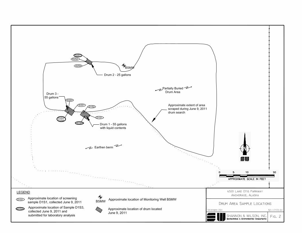


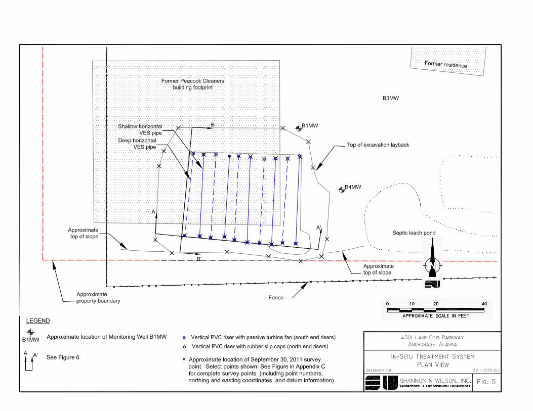

4501 Lake Otis Parkway
IN-SITU TREAMENT SYSTEM PROFILES
Anchorage, Alaska
December 2011
Fig. 6
32-1-17172-011
SHANNON & WILSON, INC.Geotechnical & Environmental Consultants
Pea Gravel
5.5' 10'
1.0'
46'-48'
B B'
A A'
35'-38'
Pea gravel
10'
5.5'
1.0'
1.5'
a = approximately 0.5' b = approximately 1.0'
a
Pea GravelPlacement Detail
1.5'Geotextile(See Appendix C)
Pea gravel
4-inch slotted PVC
Rubber slip caps Passive turbine fans
Approximate top of slope
12'
12'a
3.5' - 4.0' 4.9' - 5.3'
bb
10' 6'
Undisturbed soil
Undisturbed soil
10' 5'-12'
Excavation access ramp
2.0'
2' bgs3' bgs4' bgs
5.5' bgs6.5' bgs7.5' bgs8.5' bgs
10' bgs11' bgs12' bgs
Oxidant Application Depths
Und
istu
rbed
soi
l
Soils PID screening results:(A) <1ppm (B) <5 ppm (C) <100 ppm (D) <1,000 ppm (E) >1,000 ppmNote: >1,000 ppm soils were placed in treatment cell between the vertical risers in the lift from 7.5 to 6.5 feet bgs and not in the layback area
A
1.5'
1.0'
B
C
D
E
CBC
C
D
DC
Former log crib Former dry well
PipePipe
Former process tank
14' bgs
AFormer dry well