2010 maxima, murano, & v-6 altima; mil is on and / … · 2010 maxima, murano, & v-6...
TRANSCRIPT
1/19
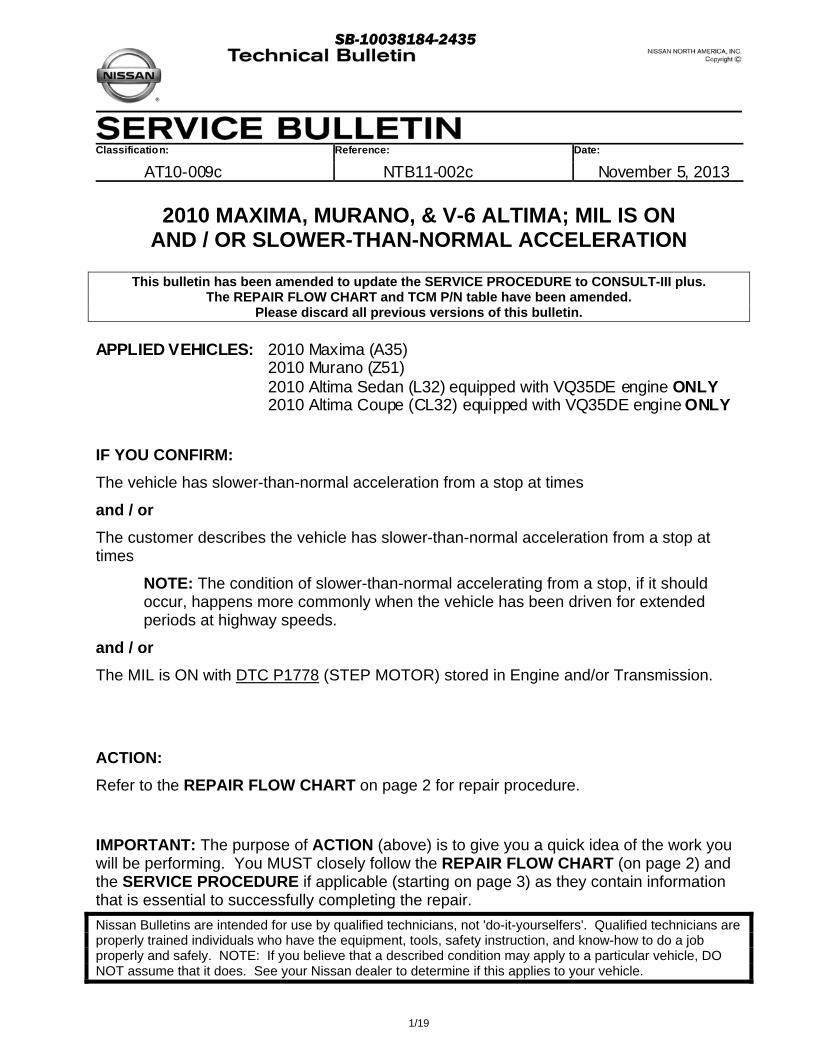
Classification: Reference: Date:
AT10-009c NTB11-002c November 5, 2013
2010 MAXIMA, MURANO, & V-6 ALTIMA; MIL IS ON AND / OR SLOWER-THAN-NORMAL ACCELERATION
This bulletin has been amended to update the SERVICE PROCEDURE to CONSULT-III plus. The REPAIR FLOW CHART and TCM P/N table have been amended.
Please discard all previous versions of this bulletin.
APPLIED VEHICLES: 2010 Maxima (A35) 2010 Murano (Z51) 2010 Altima Sedan (L32) equipped with VQ35DE engine ONLY 2010 Altima Coupe (CL32) equipped with VQ35DE engine ONLY
IF YOU CONFIRM:
The vehicle has slower-than-normal acceleration from a stop at times
and / or
The customer describes the vehicle has slower-than-normal acceleration from a stop at times
NOTE: The condition of slower-than-normal accelerating from a stop, if it should occur, happens more commonly when the vehicle has been driven for extended periods at highway speeds.
and / or
The MIL is ON with DTC P1778 (STEP MOTOR) stored in Engine and/or Transmission.
ACTION:
Refer to the REPAIR FLOW CHART on page 2 for repair procedure.
IMPORTANT: The purpose of ACTION (above) is to give you a quick idea of the work you will be performing. You MUST closely follow the REPAIR FLOW CHART (on page 2) and the SERVICE PROCEDURE if applicable (starting on page 3) as they contain information that is essential to successfully completing the repair.
Nissan Bulletins are intended for use by qualified technicians, not 'do-it-yourselfers'. Qualified technicians are properly trained individuals who have the equipment, tools, safety instruction, and know-how to do a job properly and safely. NOTE: If you believe that a described condition may apply to a particular vehicle, DO NOT assume that it does. See your Nissan dealer to determine if this applies to your vehicle.
SB-10038184-2435
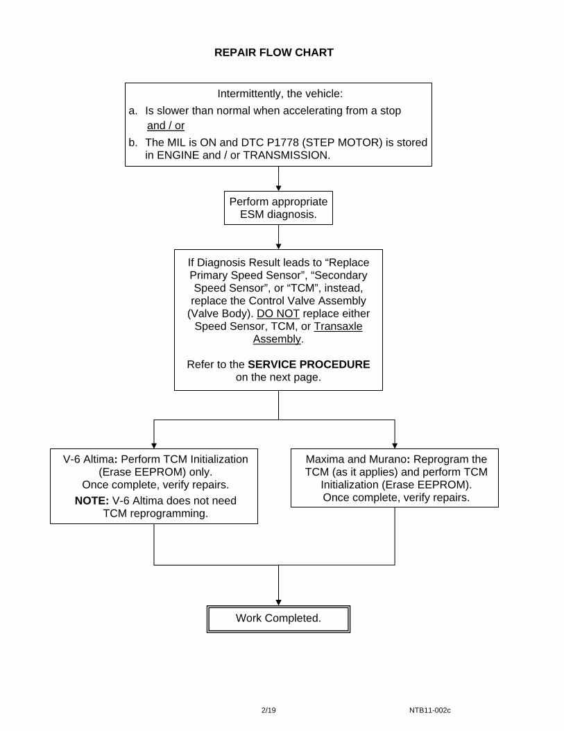
REPAIR FLOW CHART
Intermittently, the vehicle:
a. Is slower than normal when accelerating from a stop
and / or
b. The MIL is ON and DTC P1778 (STEP MOTOR) is stored in ENGINE and / or TRANSMISSION.
Maxima and Murano: Reprogram the TCM (as it applies) and perform TCM
Initialization (Erase EEPROM). Once complete, verify repairs.
If Diagnosis Result leads to “Replace Primary Speed Sensor”, “Secondary Speed Sensor”, or “TCM”, instead, replace the Control Valve Assembly
(Valve Body). DO NOT replace either Speed Sensor, TCM, or Transaxle
Assembly.
Refer to the SERVICE PROCEDURE on the next page.
Perform appropriate ESM diagnosis.
V-6 Altima: Perform TCM Initialization (Erase EEPROM) only.
Once complete, verify repairs.
NOTE: V-6 Altima does not need TCM reprogramming.
Work Completed.
2/19 NTB11-002c
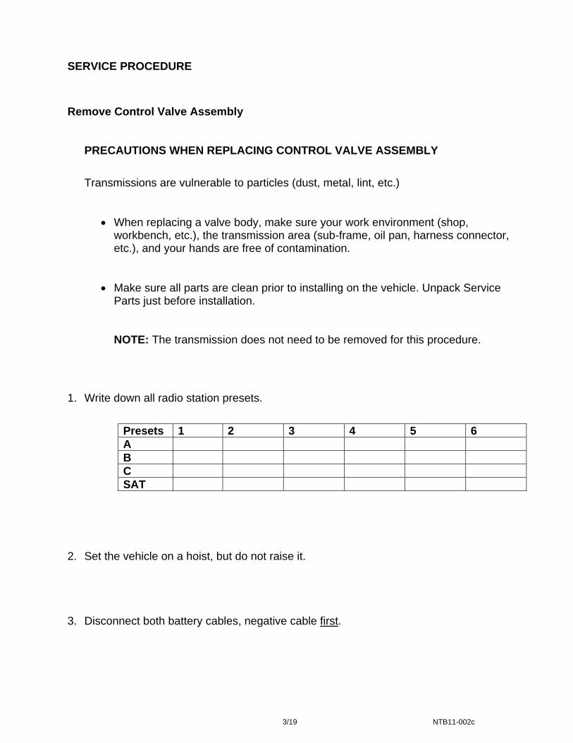
SERVICE PROCEDURE
Remove Control Valve Assembly
PRECAUTIONS WHEN REPLACING CONTROL VALVE ASSEMBLY
Transmissions are vulnerable to particles (dust, metal, lint, etc.)
• When replacing a valve body, make sure your work environment (shop, workbench, etc.), the transmission area (sub-frame, oil pan, harness connector, etc.), and your hands are free of contamination.
• Make sure all parts are clean prior to installing on the vehicle. Unpack Service Parts just before installation.
NOTE: The transmission does not need to be removed for this procedure.
1. Write down all radio station presets.
Presets 1 2 3 4 5 6 A B C SAT
2. Set the vehicle on a hoist, but do not raise it. 3. Disconnect both battery cables, negative cable first.
3/19 NTB11-002c

4. Remove the CVT dipstick, and then raise the vehicle on the hoist. 5. Remove the undercover from underneath the front bumper. 6. Remove the transmission pan drain plug and drain the CVT fluid.
WARNING: CVT Fluid may be hot.
7. Remove the oil pan bolts to remove the oil pan.
8. Disconnect CVT harness connector
F6 by turning it in the direction shown in Figure 1.
CVT connector F6
Figure 1
4/19 NTB11-002c
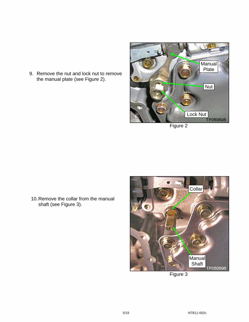
Figure 2
Figure 3
9. Remove the nut and lock nut to remove
the manual plate (see Figure 2). Nut
Manual Shaft
Lock Nut
Collar
Manual Plate
10. Remove the collar from the manual
shaft (see Figure 3).
5/19 NTB11-002c
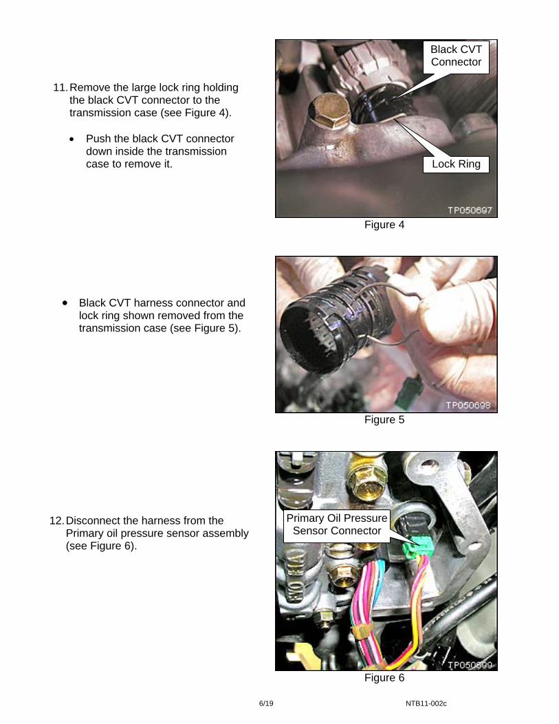
Black CVT Connector
11. Remove the large lock ring holding
the black CVT connector to the transmission case (see Figure 4).
• Push the black CVT connector
down inside the transmission case to remove it. Lock Ring
Figure 4
Figure 5
• Black CVT harness connector and
lock ring shown removed from the transmission case (see Figure 5).
12. Disconnect the harness from the
Primary oil pressure sensor assembly (see Figure 6).
Primary Oil Pressure Sensor Connector
Figure 6
6/19 NTB11-002c
13. Remove the bolts attaching the valve body to the transmission (see Figure 7).
• There are eleven (11) bolts shown and numbered for convenience.
• There are three (3) different length bolts which are identified by:
S-short
M-medium
L-long
3S 4L 5L 8L 7L 6L 9S
2M
10S
1M
11S
Figure 7
14. Carefully remove the valve body.
• Note the position of the Ratio Control Valve and attached shift link (see Figure 8).
• Be careful not to allow the Ratio
Control Valve to fall out.
Fork End
Shift Link
Ratio Control Valve. Notice Its Position.
Figure 8
7/19 NTB11-002c
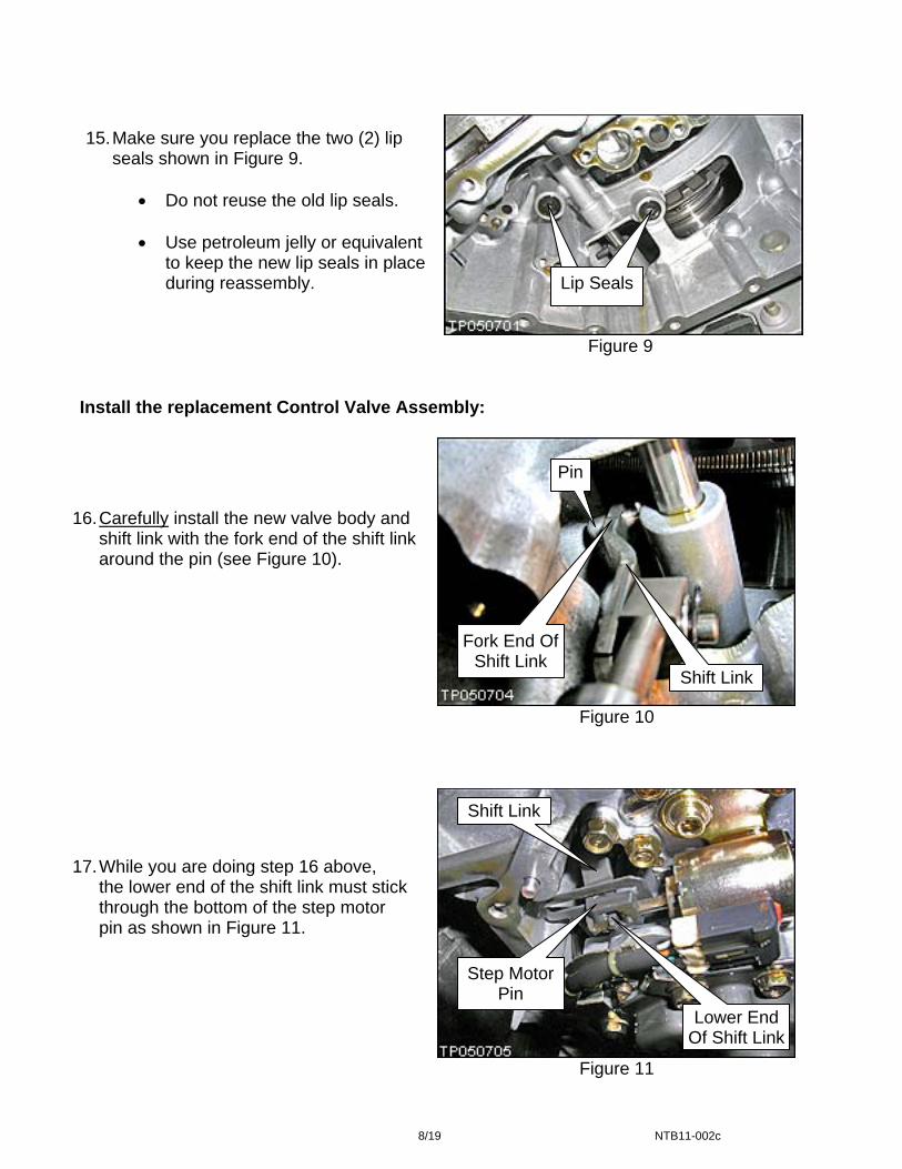
15. Make sure you replace the two (2) lip seals shown in Figure 9.
• Do not reuse the old lip seals.
• Use petroleum jelly or equivalent
to keep the new lip seals in place during reassembly. Lip Seals
Figure 9
Install the replacement Control Valve Assembly:
16. Carefully install the new valve body and shift link with the fork end of the shift link around the pin (see Figure 10).
Pin
Fork End Of Shift Link
Shift Link
Figure 10
17. While you are doing step 16 above,
the lower end of the shift link must stick through the bottom of the step motor pin as shown in Figure 11.
Shift Link
Step Motor Pin
Lower End Of Shift Link
Figure 11
8/19 NTB11-002c
18. Install finger tight the eleven (11) valve body bolts removed on page 7, step 13.
• Make sure the different lengths of bolts are installed in the correct holes (see page 7, Figure 7).
IMPORTANT CHECKS:
After you install the new valve body, make sure the upper end (fork end) of
the shift link is positioned around the pin. Space is very limited in the work area.
Install the CVT dip stick and make sure there is adequate clearance between the dipstick and the harness.
19. Torque the eleven (11) valve body bolts.
• Tightening torque: 6.9-8.9 N•m (0.7-0.9 kg-m, 61.1-78.8 in-lb) *.
• Torque sequence as per Figure 7, page 7: 6-7-5-8-4-9-3-10-2-11-1.
• Refer to Figure 7 for bolt numbering and position. 20. Reinstall the collar on the manual shaft (see page 5, step 10 and Figure 3).
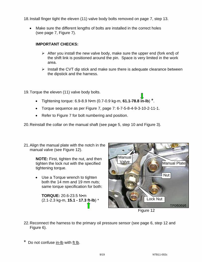
21. Align the manual plate with the notch in the
manual valve (see Figure 12).
NOTE: First, tighten the nut, and then tighten the lock nut with the specified tightening torque.
• Use a Torque wrench to tighten
both the 14 mm and 19 mm nuts; same torque specification for both:
TORQUE: 20.6-23.5 N•m (2.1-2.3 kg-m, 15.1 - 17.3 ft-lb) *
Manual Valve Manual Plate
Nut
Lock Nut
Figure 12 22. Reconnect the harness to the primary oil pressure sensor (see page 6, step 12 and
Figure 6). * Do not confuse in-lb with ft lb.
9/19 NTB11-002c
23. Install the black CVT connector in its transmission case mounting hole.
• Secure it by installing its large lock ring.
• Secure the gray F6 CVT connector to the black CVT connector.
24. Install the oil pan with a new gasket and new bolts.
• Make sure the oil pan and magnets are clean.
• Bolts tightening torque: 5.4 – 7.4 N•m (0.5 – 0.7 kg-m, 47.8 – 65.5 in-lb). *
25. Install the drain plug with new seal.
• Drain plug torque: 21.0 N•m (2.14 kg-m, 15.5 ft lb)
26. Install the undercover.
27. Connect both battery cables, negative cable last.
28. Check the fluid level.
• Add as necessary.
• Inspect for fluid leaks.
29. For Maxima and Murano: Go to “TCM Reprogramming: Determine And Perform If Needed” on page 11 to determine if the TCM needs to be reprogrammed.
a. If TCM reprogramming applies, reprogram the TCM, perform TCM initialization, and then skip to step 31.
b. If TCM reprogramming does not apply, go to step 30.
NOTE: TCM reprogramming does not apply to V-6 Altima. Go to step 30.
30. Perform TCM initialization.
• Refer to “TCM Initialization Procedure” on page 18.
31. Reset / initialize all applied systems i.e., radio, power windows, clock, sunroof, etc.
• Refer to the ESM as needed.
32. Make sure to erase DTCs from all Systems.
33. Test drive the vehicle and make sure it operates correctly, and:
• The MIL is OFF, and there are no DTCs stored in ENGINE and / or TRANSMISSION.
• If the MIL comes ON; diagnose, perform repairs, and erase DTCs.
Diagnosis and repairs beyond TCM reprogramming / initialization and valve body replacement are not covered by this bulletin.
* Do not confuse in-lb with ft lb.
10/19 NTB11-002c
TCM Reprogramming: Determine and Perform if Needed NOTE:
• Most instructions for reprogramming with CONSULT-III plus (C-III plus) are displayed on the CONSULT PC screen.
• If you are not familiar with the reprogramming procedure, click here. This will link you to the "CONSULT- III plus (C-III plus) Reprogramming" general procedure.
CAUTION:
• Connect the GR8 to the vehicle 12 volt battery and set to ECM power supply mode. If the vehicle battery voltage drops below 12.0V or rises above 15.5V during reprogramming, the TCM may be damaged.
• Be sure to turn OFF all vehicle electrical loads.
If a vehicle electrical load remains ON, the TCM may be damaged.
• Be sure to connect the AC Adapter. If the CONSULT PC battery voltage drops during reprogramming, the process will be interrupted and the TCM may be damaged.
• Turn off all external Bluetooth® devices (e.g., cell phones, printers, etc.) within
range of the CONSULT PC and the VI. If Bluetooth® signal waves are within range of the CONSULT PC during reprogramming, reprogramming may be interrupted and the TCM may be damaged.
11/19 NTB11-002c

1. Connect the CONSULT PC to the vehicle to begin the reprogramming procedure. 2. Start CONSULT-III (C-III) plus. 3. Wait for the plus Vehicle Interface (VI) to be recognized.
• The serial number will display when the plus VI is recognized. 4. Select Re/programming, Configuration.
VI is recognized
Step 4
Figure 13 5. Follow the on-screen instructions and navigate C-III plus to the screen shown in
Figure 14 on the next page.
12/19 NTB11-002c
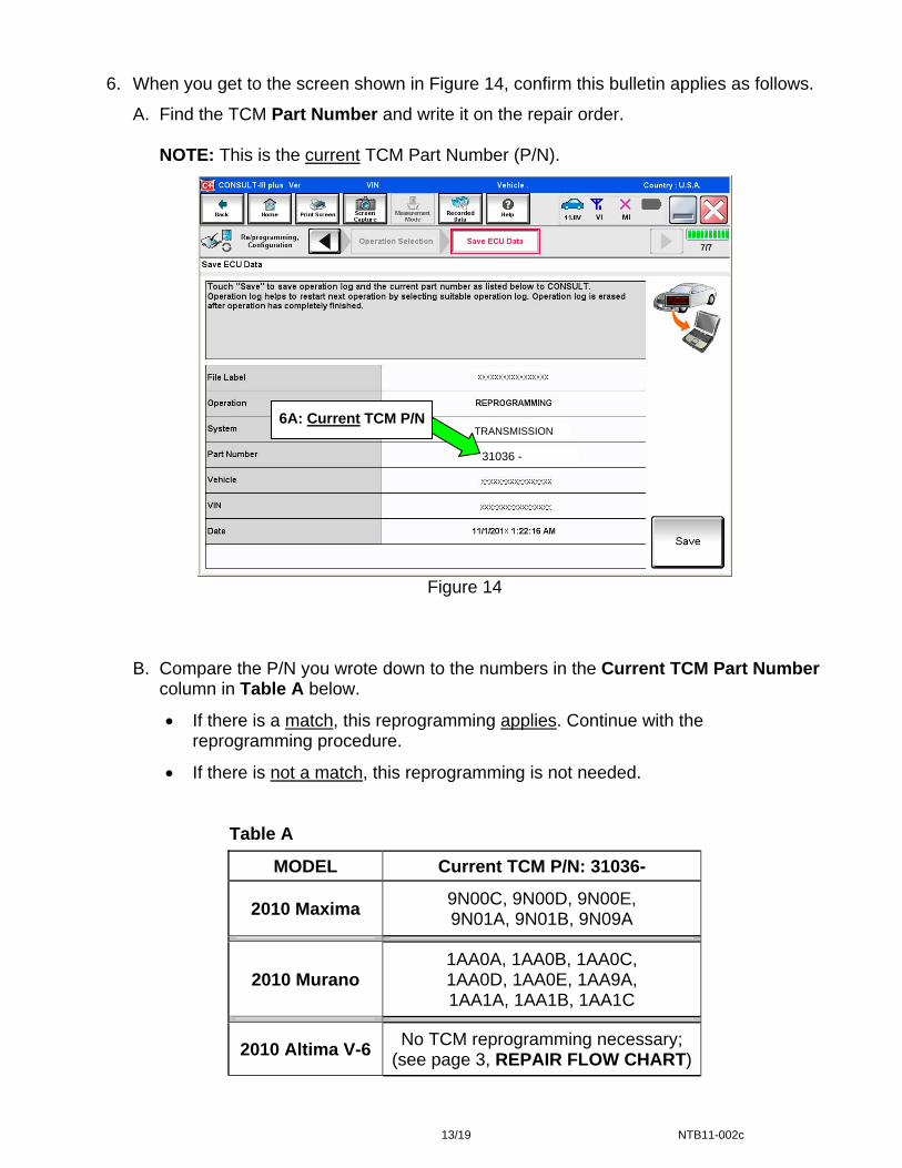
6. When you get to the screen shown in Figure 14, confirm this bulletin applies as follows.
A. Find the TCM Part Number and write it on the repair order.
NOTE: This is the current TCM Part Number (P/N).
TRANSMISSION 6A: Current TCM P/N
Figure
B. Compare the P/N you wrote down to thecolumn in Table A below.
• If there is a match, this reprogrammireprogramming procedure.
• If there is not a match, this reprogram
Table A
MODEL Curr
2010 Maxima 9N09N
2010 Murano 1AA1AA1AA
2010 Altima V-6 No TCM r(see page
13/19
31036 -
14
numbers in the Current TCM Part Number
ng applies. Continue with the
ming is not needed.
ent TCM P/N: 31036-
0C, 9N00D, 9N00E, 01A, 9N01B, 9N09A
0A, 1AA0B, 1AA0C, 0D, 1AA0E, 1AA9A, 1A, 1AA1B, 1AA1C
eprogramming necessary; 3, REPAIR FLOW CHART)
NTB11-002c

7. Follow the on-screen instructions to navigate C-III plus and reprogram the TCM.
NOTE:
• In some cases, more than one new P/N for reprogramming is available.
In this case, the screen in Figure 15 displays.
Select and use the reprogramming option that does not have the message “Caution! Use ONLY with NTBXX-XXX”.
• If you get this screen and it is blank (no reprogramming listed), it means there is no
reprogramming available for this vehicle. Close C-III plus and refer back to ASIST for further diagnosis.
IMPORTANT: If C-III plus locks up or freezes at this point or displays “cannot complete reprogramming, the CONSULT PC is set up with User Rights. Reprogramming can be completed with Administrator log in”, the TOUGHBOOK settings need to be changed so that Users have full access rights. See your Dealership’s IT System Administrator for details.
TRANSMISSION
Figure 15
14/19 NTB11-002c
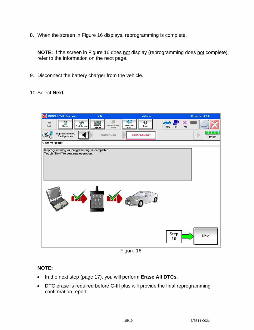
8. When the screen in Figure 16 displays, reprogramming is complete.
NOTE: If the screen in Figure 16 does not display (reprogramming does not complete), refer to the information on the next page.
9. Disconnect the battery charger from the vehicle. 10. Select Next.
Step 10
Figure 16
NOTE:
• In the next step (page 17), you will perform Erase All DTCs.
• DTC erase is required before C-III plus will provide the final reprogramming confirmation report.
15/19 NTB11-002c
TCM recovery:
Do not disconnect plus VI or shut down C-III plus if reprogramming does not complete.
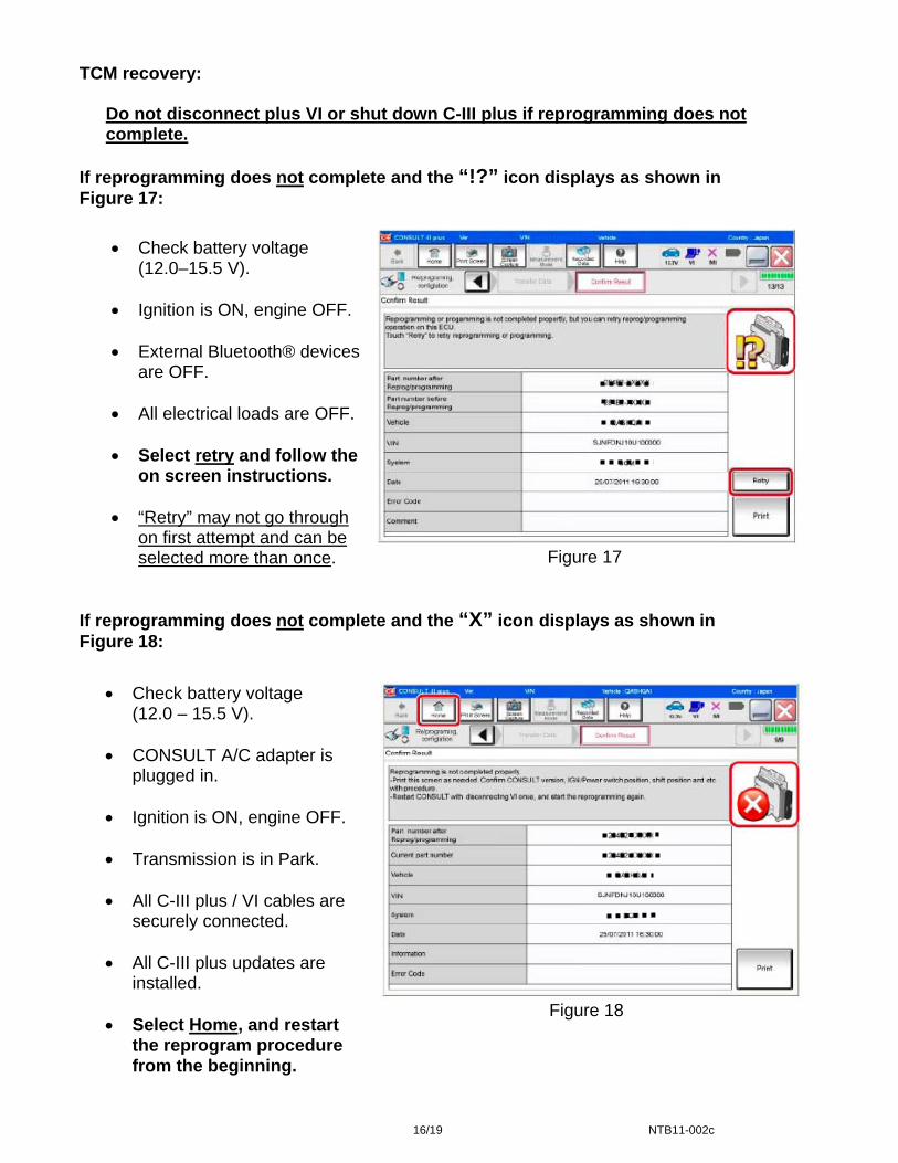
If reprogramming does not complete and the “!?” icon displays as shown in Figure 17:
Figure 17
If reprogramming does not complete and the “X” icon displays as shown in Figure 18:
Figure 18
• Check battery voltage (12.0–15.5 V).
• Ignition is ON, engine OFF.
• External Bluetooth® devices
are OFF.
• All electrical loads are OFF.
• Select retry and follow the on screen instructions.
• “Retry” may not go through
on first attempt and can be selected more than once.
• Check battery voltage (12.0 – 15.5 V).
• CONSULT A/C adapter is
plugged in.
• Ignition is ON, engine OFF.
• Transmission is in Park.
• All C-III plus / VI cables are securely connected.
• All C-III plus updates are
installed.
• Select Home, and restart the reprogram procedure from the beginning.
16/19 NTB11-002c
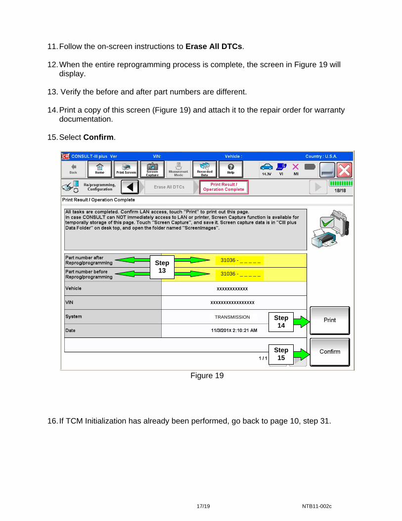
11. Follow the on-screen instructions to Erase All DTCs. 12. When the entire reprogramming process is complete, the screen in Figure 19 will
display. 13. Verify the before and after part numbers are different. 14. Print a copy of this screen (Figure 19) and attach it to the repair order for warranty
documentation. 15. Select Confirm.
Step 13
31036 - _ _ _ _ _
31036 - _ _ _ _ _
Step 14
TRANSMISSION
Step 15
Figure 19 16. If TCM Initialization has already been performed, go back to page 10, step 31.
17/19 NTB11-002c
TCM Initialization Procedure
NOTE: If reprogramming is not performed, make sure TCM initialization is performed as part of the control valve assembly replacement.
1. Set the parking brake with the selector lever in “P” (Park).
2. Attach C-III plus to the vehicle with the plus VI.
3. Turn the ignition ON (engine OFF - not running).
4. Open C-III plus and navigate screens to: Diagnosis One System >> Transmission >> Calibration Data.
5. Print the Calibration Data and save a copy (or write down the calibration data).
6. Select Transmission Self Diagnostic Results.
7. Perform the initialization (EEPROM erase) procedure as follows:
a. Press and hold the brake pedal.
b. Shift the selector lever to “R” (Reverse).
c. Press and hold the accelerator pedal down about one-third, but no more than halfway.
• The purpose of this step is to get both the wide open throttle and closed throttle position signals to read “OFF” at the same time.
d. Press Erase on the C-III plus screen.
e. Shift the selector lever to “P” (Park).
NOTE: If the EEPROM erase was successful, the “P” in the instrument display will have a short delay (about 1.5 seconds) before illuminating after shifting to park.
f. Remove foot from brake and accelerator.
g. Turn the ignition OFF.
h. Wait 5 seconds.
i. Turn the ignition ON.
8. On C-III plus, select Transmission Calibration Data again. 9. Print the Calibration Data and save a copy (or write down the calibration data).
10. Compare the values between the first and second Calibration Data prints.
• The procedure is complete if the values are different.
• If the values are not different, repeat the procedure. 11. Make sure to erase DTCs from all systems.
12. Return to page 10, step 31.
18/19 NTB11-002c

PARTS INFORMATION
VEHICLE DESCRIPTION PART # QTY2010 Maxima (A35) Valve Assy - Control 31705-1XE2B 1 2010 Murano (Z51) Valve Assy - Control 31705-1XE1E 1
2010 Altima (C/L32) w/VQ35DE Valve Assy - Control 31705-1XE2C 1 ALL Gasket - Oil Pan 31397-1XE0A 1 ALL Nissan CVT Fluid (1) 999MP-NS200P (2) ALL Washer - Thrust (lip seal) 31528-1XA01 2 ALL Bolt (oil pan) 31377-1XD0D 20 ALL Seal - O Ring (drain plug) 31526-1XA01 1
(1) Order Nissan CVT NS-2 Fluid through the Nissan Maintenance Advantage program: Phone: 877-NIS-NMA1 (877-647-6621) Website order via link on dealer portal www.NNAnet.com and click on “Tire Advantage” link.
(2) Up to eight (8) quarts. CLAIMS INFORMATION
Submit a Primary Failed Part (PP) line claim using the following claims coding.
DESCRIPTION PFP OP CODE SYM DIA FRT RPL CONTROL VALVE ASSY JD48AA (2)
REPROGRAM TCM (1) JE99AA ZE 32 (2) (3)
(1) Reference the Parts Information Table and use the applicable Control Valve Assy P/N as the PFP.
(2) Reference the current Nissan Warranty Flat Rate Manual and use the indicated flat rate time.
(3) FRT allows adequate time to access DTCs and reprogram TCM. No other diagnostic procedures subsequently required. Do NOT claim any Diagnostic Op Codes with this claim.
19/19 NTB11-002c